Decespugliatore a scoppio ISTRUZIONI D’USO - valex.it · Riempire il contenitore di benzina fino...
28
Final dimension: A5 S491970 01.12.2017 ATTENZIONE! Prima di usare la macchina, leggete e comprendete le istruzioni di sicurezza e le istruzioni d’uso fornite WARNING! Before using the machine, read and understand the supplied safety instructions and operating instructions Decespugliatore a scoppio ISTRUZIONI D’USO Istruzioni originali Internal combustion brush cutter OPERATING INSTRUCTIONS Translation of the original instructions TEXAS 43
Transcript of Decespugliatore a scoppio ISTRUZIONI D’USO - valex.it · Riempire il contenitore di benzina fino...

Final dimension: A5
S49197001.12.2017
ATTENZIONE! Prima di usare la macchina, leggete e comprendete le istruzioni di sicurezza e le istruzioni d’uso forniteWARNING! Before using the machine, read and understand the supplied safety instructions and operating instructions
Decespugliatore a scoppio ISTRUZIONI D’USO Istruzioni originali
Internal combustion brush cutter OPERATING INSTRUCTIONS Translation of the original instructions
TEXAS 43

- 2 -

- 3 -

- 4 -
- 5 -

- 6 -

- 7 -

- 8 -
i
SIMBOLOGIAOsservate con attenzione la simbologia della fig.B e memorizzate il rispettivo significato. Una corretta interpretazione dei simboli consente un uso più sicuro della macchina.
1. Lotto di costruzione della macchina2. Modello e codice prodotto3. Dati tecnici4. Dati motore5.Fissare l’impugnatura anteriore dopo la
freccia di limite6. Carburante7. Arresto motore8. Valvola dell’aria
kW kiloWattHp horsepowermm millimetricm centimetrim metrimin-1 giri al minutos secondol litrikg chilogrammidB decibel
___________________________________
Vi ringraziamo per averci preferito nella scelta di questa macchina, di seguito chiamata “dece-spugliatore a scoppio”.!! ATTENZIONE! Il decespugliatore a scoppio è
idoneo a tagliare l’erba e piccoli arbusti.Ogni altro uso è vietato. Questo istruzioni riportano le informazioni e quanto ritenuto necessario per il buon uso, la conoscenza e la normale manutenzione della macchina. Esse non riportano le informazioni sulle tecniche di manutenzione delle superfici erbose; l’utilizzatore troverà maggiori notizie su libri e pubblicazioni specifiche o partecipando a corsi di specializzazione.
COMPONENTIFare riferimento alla fig. A e seguenti:
1 Impugnatura posteriore e gruppo comandi 2 Interruttore spegnimento motore3 Leva comando gas carburatore (acceleratore)4 Blocco di sicurezza acceleratore5 Pompa adescamento carburatore6 Motore a scoppio7 Leva comando aria8 Maniglia per avviamento a strappo9 Filtro aria
10 Candela11 Tappo carburante12 Impugnatura anteriore13 Testa di taglio14 Protezione15 Lametta regolafilo16 Elemento di taglio17 Staffa aggancio imbracatura18 Serbatoio carburante19 Asta supporto/trasmissione20 Giunto di supporto impugnature24 Anello di limitazione area montaggio impu-
gnatura25 Marmitta26 Imbracatura28 Lama (se presente)29 Regolatore corsa acceleratore30 Punto di ingrassaggio

- 9 -
INSTALLAZIONE
!! ATTENZIONE! La Ditta costruttrice declina ogni responsabilità per gli eventuali danni diretti e/o indiretti causati da una errata installazione.
TRASPORTOPulite la macchina ed utilizzate sempre il suo imballo; questo la preserverà da urti, polvere e umidità che ne possono compromettere il regolare funzionamento. Durante il trasporto staccate il cappuccio della candela, attendete che si sia raffreddata e scari-cate completamente il serbatoio del carburante.Con elementi di taglio a lama, smontate la lama e conservatela in un imballo protettivo.Se trasportata su un veicolo assicurate bene la macchina con cinghie, in modo da evitare spostamenti improvvisi dovuti a frenate, curve, dossi ecc.
MOVIMENTAZIONELa movimentazione su una superficie non erbosa deve avvenire sempre a motore spento. Afferrate la macchina con entrambe le mani e portatela al fianco, rivolta verso il basso e lontana dal vostro corpo.Sostenetela sollevata da terra e non fate stri-sciare l’elemento di taglio sul terreno. A causa della lunghezza ragguardevole fate attenzione a non colpire i piedi, le gambe oppure persone o oggetti.Dopo l’uso appoggiate la macchina senza battere e con tappo del carburante rivolto verso l’alto; evitate di appoggiarla su piani in pendenza o su veicoli in quanto potrebbe rotolare e cadere. Non appoggiare mai il disco lama sul terreno, per evitare che si fletta fino a piegarsi in modo permanente o si danneggi.
MESSA IN SERVIZIONel luogo che utilizzerete la macchina è oppor-tuno considerare:- che agenti atmosferici avversi come pioggia o
temporale non siano presenti.- che attorno sia prevista un’ampia zona opera-
tiva libera da impedimenti.- che vi sia una buona illuminazione naturale o
artificiale.- che il tappeto erboso sia idoneo e l’erba non
sia eccessivamente alta, non sia bagnato e sia privo di sassi, radici sporgenti, rami, tubi, cavi elettrici, oggetti ecc. che danneggerebbero la
macchina e metterebbero in pericolo l’utilizza-tore.
- che estranei, bambini ed animali non siano presenti.
ASSEMBLAGGIO!! ATTENZIONE! Prima di effettuare le
seguenti operazioni scollegate il cappuccio dalla candela.Estraete la macchina ed i componenti e verificate visivamente la loro perfetta integrità.Procedete nel seguente ordine osservando atten-tamente le fig. A-C-D-E e i relativi paragrafi:1. assemblaggio del gruppo motore all’asta di
trasmissione (o giunto flessibile di trasmis-sione)
2. collegamento del cavo dell’acceleratore al carburatore; se già assemblato procedete oltre
3. collegamento dei cavi elettrici tra gruppo comando al motore; se già assemblati pro-cedete oltre
4. assemblaggio impugnatura anteriore5. assemblaggio protezione della zona di taglio
e lametta tagliafilo6. installazione rocchetto di taglio (o lama di
taglio dove consentito) e relativi componenti7. fissaggio imbracatura e regolazione lunghezza.
Montaggio del gruppo motore all’asta di tra-smissione (fig.E)1. Inserire l’estremità a forma di cono dell’asta di
trasmissione (18) nel gruppo motore (19) in corrispondenza della frizione.
2. Avvitare tutte viti di fissaggio (20)3. Verificate il corretto montaggio4. Effettuate il collegamento del cavo accele-
ratore e dei cavi elettrici (vedi sotto).
Collegamento del cavo acceleratore al carburatore1. Smontate il coperchio del filtro aria (pos.9)2. Con un dito ruotate il dispositivo presente
sul carburatore e trattenetelo in posizione3. Infilate a fondo il cavo e la guaina nel foro
filettato ed allineate il cavo con l’aggancio presente sul carburatore
4. Avvitate a metà la vite forata e serrate il dado5. Rilasciate il dispositivo del carburatore
che automaticamente ruoterà mettendo in tensione il cavo
6. Verificate che la testa del cavo sia corretta-mente inserita
7. Verificate il corretto collegamento premendo alcune volte l’acceleratore (pos.3): il dispo-

- 10 -
sitivo che trattiene il cavo deve ruotare entro un arco tra minimo e massimo, delimitato da 2 battute d’arresto del carburatore, se necessario regolare la vite forata per dare minore/maggiore tensione al cavo.
8. Rimontare il coperchio del filtro
Collegamento dei cavi elettrici1. Infilare tra di loro gli spinotti dei cavi
elettr ici r ispettando la connessione maschio-femmina, indipendentemente dai colori dei cavi.
2. Sistemare i tubetti in gomma in modo che gli spinotti metallici siano completamente protetti
3. Posizionare i cavi nella macchina in modo che non siano esposti o di intralcio
4. Verificate il corretto collegamento.5. Fissare la canaletta passacavi al tubo cen-
trale del decespugliatore usando le fascette plastiche da elettricista.
MONTAGGIO COMPONENTIMontaggio impugnatura anteriore (fig. C)!! ATTENZIONE! È obbligatorio montare
l’impugnatura tra i 2 anelli di fermo, in modo da mantenere una distanza minima di 250mm con l’impugnatura posteriore.
1 Posizionare il supporto di gomma attorno all’asta di alluminio nella posizione più con-fortevole.
2 Fissare al supporto in gomma le 2 parti dell’im-pugnatura (12) tramite le 4 viti. Verificare che la barriera sia montata a sinistra dell’asta (per mancini montarla a destra).
Montaggio protezione (fig. D)!! ATTENZIONE! Nella protezione lato interno
è fissata una lametta che ha la funzione di tagliare il filo troppo lungo. Maneggiatela con attenzione ed indossate i guanti protettivi.1. Installare la protezione (14) sul supporto
predisposto sulla testa di taglio (13).2. Fissare la protezione con le 2 viti .3. Se la lametta tagliafilo (15) è fornita smon-
tata, è necessario applicarla alla protezione e fissarla con le viti.
4. Rimuovere la copertura protettiva sul taglien-te della lametta (se presente).
Montaggio rocchetto semiautomatico con fili flessibili (fig.E)Rocchetto con foro filettato:1. Inserire la flangia superiore scanalata nell’al-
bero scanalato.2. Avvitare il rocchetto con filetto sinistro (16)
bloccando la rotazione dell’albero tramite l’utensile inserito nel foro; per avvitare girare in senso antiorario
Montaggio lama (se presente e se compatibile con la macchina) (fig. E)!! ATTENZIONE! E’ vietato installare un disco
lama a sega. L’uso di elementi di taglio non autorizzati da queste istruzioni provocano pericoli molto gravi.!! ATTENZIONE! Dove indicato è vietato in-
stallare una lama a punte o a stella. Osservate la figura N per il tipo di lama che può essere montato sulla macchina.!! ATTENZIONE! La lama ha parti affilate.
Indossate guanti di protezione e maneggiatela con attenzione.1. Montare i componenti nella sequenza indi-
cata in fig. E2. Prestare attenzione al senso di rotazione della
lama (28) e al senso della freccia impressa nella protezione che indica la rotazione della macchina.
3. Bloccare la rotazione dell’albero scanalato tramite un utensile inserito nel foro.
4. Avvitare il dado sinistro; per avvitare girare in senso antiorario
Montaggio della imbracatura (fig.P)1. Indossate la imbracatura come illustrato in
fig.P22. Agganciate la fibbia centrale fig.P3 3. Agganciate il moschettone alla macchina fig.
P4 e regolate la protezione laterale in modo che risulti interposta tra il fianco dell’opera-tore e la macchina.
5. Regolate le cinghie dell’ imbracatura in modo da ottenere l’altezza ottimale di lavoro, a questo scopo fate oscillare lateralmente la macchina senza avviarla.
Nb: La imbracatura è dotata di un meccanismo ad apertura veloce che sgancia la macchina in caso di emergenza. Per azionarlo, tirate il nastro rosso della cintura (fig.P5).
Verificate di aver montato correttamente tutti i componenti e di aver serrato tutte le viti; in caso

- 11 -
di dubbio rivolgetevi al vostro negoziante o a un centro assistenza autorizzato.Togliete tutte le chiavi o attrezzi dalla macchina che vi sono serviti per l’assemblaggio.
!! ATTENZIONE! Procedete ora con la messa in servizio del motore leggendo ed applicando le istruzioni del capitolo seguente:
MOTORE A SCOPPIO CICLO 2 TEMPI (2T)
!! ATTENZIONE! Ogni operazione indicata di seguito deve essere effettuata con il motore spento e interruttore in posizione “stop”.!! ATTENZIONE! Indossate guanti ed occhiali
di protezione.La macchina viene fornita senza carburante, che è composta da una miscela di benzina e olio lubrificante .!! ATTENZIONE! Il motore funziona esclusi-
vamente con miscela olio-benzina ottenuto utilizzando olio nella percentuale indicata sul foglio specifiche. Nel caso non si utilizzi questa miscela il motore si guasterà in modo irreparabile con il decadimento immediato della garanzia.
PREPARAZIONE DELLA MISCELAUtilizzare olio sintetico tipo JASO FC GRADE o ISO EGC GRADE che garantisce un migliore rendimento, una ridotta fumosità e una maggiore durata del motore.
Come preparare una miscela olio benzina al 2,5% di olio (1:40)Utilizzare un contenitore ed un misurino (non inclusi) per miscelare 25 cc di olio (0,025 litri) in 1000 cc (1 litro) di benzina. Usare solo benzina per automobili senza piombo (benzina verde o eurosuper) con un minimo di 90 ottani. Agitare bene la miscela prima dell’uso. È con-sigliabile preparare una quantità di miscela non superiore a quella necessaria per un pieno del serbatoio.Lo stoccaggio della miscela per lunghi periodi ne comporta un rapido deterioramento; si consiglia di aggiungere specifici additivi per evitare che la miscela si deteriori col tempo, con conseguente malfunzionamento del motore e problemi di avviamento.Conservate la benzina e l’olio in contenitori ido-nei, omologati, in un luogo sicuro e fuori dalla portata dei bambini.
Come preparare la miscela olio benzina al 2,5% di olio utilizzando il contenitore fornito (se pre-sente, fig. F):Riempire il contenitore di benzina fino al livello marcato 1.40, aggiungere l’olio fino al livello marcato 600. Chiudere il tappo ed agitare.
RIFORNIMENTO CARBURANTE !! ATTENZIONE! Pericolo di incendio ed
esplosione. Effettuare il rifornimento di carbu-rante a motore spento, in un luogo all’aperto e ventilato. Se versato sulla macchina o sul pavimento, asciugare bene prima di avviare la macchina.!! ATTENZIONE! Pericolo di incendio ed
esplosione. Non versare il carburante sulle superfici calde del motore.Utilizzare solo miscela olio-benzina come sopra specificato. Non utilizzare mai benzina senza olio, carburante sporco o vecchio oppure con-tenente alcool.Fate attenzione a non lasciare penetrare nel serbatoio acqua o sporco. 1. Posizionate stabilmente la macchina su una
superficie orizzontale.2. Svitare il tappo serbatoio (pos.11) ruotando
in senso antiorario.3. Riempire il serbatoio (pos.18) senza farlo
tracimare utilizzando un imbuto largo (non incluso). Osservare eventuali indicazioni poste sul serbatoio; se non sono presenti, mantenere il livello massimo 3cm sotto il bordo.
4. Avvitare bene il tappo ruotando in senso orario.
5. Pulire con uno straccio eventuali gocce di benzina sulla macchina.
AVVIAMENTO ED ARRESTO
!! ATTENZIONE! Prima di avviare la macchina è obbligatorio indossare tutti i dispositivi di protezione individuale (non inclusi), citati nelle Avvertenze di sicurezza.!! ATTENZIONE! Non avviare se la protezione
dell’elemento di taglio è mancante.!! ATTENZIONE! Durante le fasi di avvia-
mento l’organo di taglio potrebbe mettersi in rotazione. Mantenere perciò una distanza di sicurezza. !! ATTENZIONE! Prima di procedere nell’av-
viamento del motore verificare di aver

- 12 -
effettuato le operazioni richieste dai capitoli precedenti per la messa in servizio della macchina e del motore.!! ATTENZIONE! Prima di procedere all’avvia-
mento del motore verificare che nel serbatoio ci sia una quantità sufficiente di carburante.
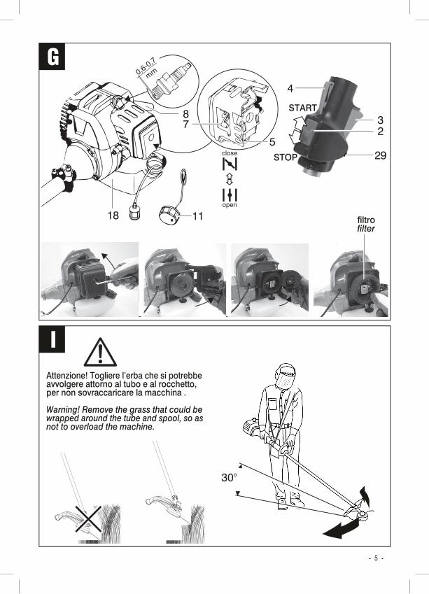
La macchina è dotata di frizione centrifuga, con il motore al minimo (non accelerato) gli organi di taglio non girano. Per fermare la rotazione degli organi di taglio è sufficiente rilasciare l’accelera-tore in modo che il motore raggiunga, in alcuni secondi, il regime di minimo. Se al regimo di minimo l’elemento di taglio gira, rivolgetevi ad un centro di assistenza autorizzato per un controllo della macchina.Osservate con attenzione la fig.G ed imparate a memoria tutti i comandi presenti nell’impugna-tura di comando. Il comando dell’acceleratore è dotato di una leva di blocco atta ad impedire l’avviamento involontario degli organi di taglio.
Descrizione componenti motore e comandi (fig.G):
2 Interruttore accensione/spegnimento3 Comando acceleratore4 Leva blocco di sicurezza5 Pompa adescamento del carburatore7 Comando aria8 Maniglia di avviamento 9 Filtro dell’aria
10 Candela di accensione 18 Serbatoio carburante 11 Tappo serbatoio carburante
Avviamento a motore freddo (fig. G)1. Spostare l’interruttore di accensione/spegni-
mento (2) in posizione “START” ”I”.2. Adescare il circuito del carburante azionando
10 volte la pompa di adescamento (5); il circuito è adescato quando si vede il liquido carburante nella pompa, se necessario azionare ancora la pompa.
3. Spostare il comando aria (7) in posizione “close” .
4. Con la mano destra afferrate la maniglia di avviamento (8), tirate lentamente fino a trovare resistenza e poi tirate energicamente con un colpo deciso; rilasciate la maniglia ad avviamento avvenuto. Se il motore non si avvia ripetete questa operazione alcune volte; se l’avvio non va a buon fine consultate il
capitolo “Problemi, cause e rimedi”. ATTENZIONE! In questa fase l’organo di
taglio potrebbe mettersi in rotazione.5. A motore avviato spostare il comando aria
(7) in posizione “OPEN” . Nota: non la-sciate troppo tempo la leva nella posizione di avvio altrimenti il motore tenderà ad ingolfarsi.
Avviamento a motore caldo (fig. G)1. Spostare l’interruttore di accensione/
spegnimento (2) in posizione “START” ”I” e assicurarsi che il comando aria (7) sia posizionato su ‘OPEN’.
2. Se necessario, adescare il circuito del carburante azionando 10 volte la pompa di adescamento (5); il circuito è adescato quando si vede il liquido carburante nella pompa, se necessario azionare ancora la pompa.
3. Tirare la maniglia di avviamento (8) fino all’avviamento del motore.
Spegnimento del motore (fig.G)Rilasciare l’acceleratore e spostare l’interrut-tore accensione/spegnimento (2) in posizione “STOP” ”O”.Il motore, le parti meccaniche rotanti e l’ele-mento di taglio girano ancora per alcuni secondi dopo aver spento la macchina; durante la fase di arresto tutte le parti in rotazione non devono essere toccate.
RodaggioNelle prime 10 ore di funzionamento il motore non deve essere sollecitato eccessivamente; perciò all’interno di questo periodo non far funzionare a vuoto al massimo numero di giri e durante l’uso non forzare accelerando a fondo.
Vi consigliamo di ripetere queste operazioni alcune volte prima di iniziare il lavoro in modo da familiarizzare il più possibile con i comandi.Se osservate delle anomalie di funzionamento spegnete la macchina e consultate il capitolo “Problemi, cause e rimedi”.Quando non lavorate spegnete la macchina.

- 13 -
ISTRUZIONI D’USODopo aver letto attentamente i capitoli preceden-ti, seguite scrupolosamente queste istruzioni che vi permetteranno di ottenere il massimo delle prestazioni.Procedete con calma in modo da prendere familiarità con tutti i comandi; solo dopo aver acquisito una buona esperienza riuscirete a sfruttarne a fondo tutte le potenzialità.
ROCCHETTO E FILOUtilizzare solo rocchetti con filo di taglio in ma-teriale plastico a sezione circolare; per diametro vedere i dati tecnici allegati. È vietato l’utilizzo di fili metallici, catene o altro. L’uso di elementi di taglio non consentiti genera pericoli molto gravi.
Il filo corto od usurato dà un basso rendimento di taglio, perciò seguite le istruzioni per la regolazione della sua lunghezza come indicato di seguito.Uso del rocchetto semiautomatico “tap & go”:- Per allungare il filo percuotere la parte mobile
del rocchetto sul terreno con la macchina in moto.
- La lunghezza del filo è regolata automatica-mente dalla lametta (pos.15) presente nella protezione.
LAMAL’efficienza della lama (pos.28) è fondamentale per la buona riuscita del lavoro che vi state apprestando ad eseguire, mantenetela sempre affilata e in perfette condizioni; non utilizzate lame danneggiate o lame a sega. La dimensioni caratteristiche della lama sono il diametro di taglio e lo spessore: osservate quanto indicato nei dati tecnici allegati e in figura N per individuare l’accessorio corretto.L’uso di elementi di taglio non consentiti genera pericoli molto gravi.
TAGLIO DEL PRATO ERBOSOProcedete con calma e seguite attentamente le indicazioni di seguito riportante:- Osservate le figure I ed agite di conseguenza.- Eliminate dal prato erboso gli oggetti estranei
come sassi, fili, tubazioni, rami e oggetti ecc. Fate attenzione ai pozzetti, alle radici e ai punti sporgenti di innaffiatura.
- Evitate di calpestare l’erba per non schiacciarla.- Indossate i dispositivi di protezione individuale
elencati nel cap. Avvertenze.
- Controllate il livello dell’olio motore (solo per motore 4 tempi).
- Procuratevi il carburante necessario, un imbuto e uno straccio e fate rifornimento nel serba-toio. Non effettuare il rifornimento sul tappeto erboso perché il carburante è velenoso per la vegetazione.
- Se il manto erboso è alto e/o particolarmente folto sarà necessario effettuare due o più passate, partendo dall’alto.
Operatore:Mantenete la posizione d’uso illustrata nelle figura I, cioè con il decespugliatore al fianco ed elemento di taglio rivolto in avanti. Non mettetevi mai davanti allo scarico dei gas o in prossimità dell’elemento di taglio.Fate attenzione al movimento dei vostri piedi che devono sempre rimanere a distanza di sicurezza; in particolare prestare la massima attenzione nei movimenti per far arretrare la macchina, nell’inversione di marcia e nel taglio su un terreno in pendio. È necessario che i piedi siano ben stabili in posizione sicura.Per evitare problemi muscolari derivanti da una postura scorretta, cercate per quanto possibile di mantenere diritta la schiena ed evitate di piegarvi in avanti, distendete poco in avanti le braccia e mantenete l’equilibrio senza appoggiarvi sulla macchina. Avviamento degli organi di taglio (fig. G):La macchina è dotata di una frizione centrifuga, con il motore al minimo (non accelerato) l’ele-mento di taglio non gira.Il comando dell’acceleratore (3) è dotato di una leva di blocco (4) atta ad impedire l’avviamento involontario dell’elemento di taglio.Per avviare l’organo di taglio procedere come segue :
1. Impugnare saldamente con la mano destra l’impugnatura posteriore e afferrare salda-mente l’impugnatura anteriore
2. Sbloccare con il palmo la leva di blocco (4) e premere il comando dell’acceleratore (3)
3. Per fermare l’elemento di taglio è sufficiente rilasciare il comando dell’acceleratore ed attendere che il rocchetto (o la lama) si arresti e che il motore torni al regime di minimo.

- 14 -
Taglio:L’uso delle cuffie antirumore riduce anche eventuali avvertimenti sonori per richiamare la vostra attenzione (esempio il clacson di un veicolo), evitate quindi di stazionare in luoghi di transito e osservate sempre con attenzione l’area in cui operate.Infilate la imbracatura e afferrate la macchina sempre nelle due impugnature. Avviate la macchina e procedete subito al taglio dell’erba. Si consiglia di avanzare nel lato lungo del prato, per fasce parallele, in modo da ridurre al minimo i cambi di direzione ed ottenere un buon effetto visivo dell’erba tagliata.Evitate di passare sopra gli accumuli di erba ta-gliata precedentemente per non i sovraccaricare il funzionamento del motore.Tagliate l’erba facendo oscillare a destra e a sinistra la macchina ed avanzate lentamente tenendola inclinata in avanti di circa 30° (fig.I).La rotazione dell’elemento di taglio, oltre a taglia-re l’erba, potrebbe eiettare anche piccoli oggetti; prestate attenzione quando passate nei bordi del prato per non scagliare sassi, ghiaia, lapillo, corteccia ecc. che danneggiano la macchina e vengono eiettati attorno con pericolo di colpire persone o cose.Prestate attenzione agli ostacoli (tronchi, ra-dici sporgenti, pozzetti, marciapiedi, punti di illuminazione ecc.), aggirateli a distanza e suc-cessivamente con una forbice o un tagliabordi completate il taglio.Non fate urtare la macchina contro ostacoli fissi come un muro, una recinzione, un tronco d’albero ecc. perché potrebbe danneggiarsi e generare pericolo.Se la vegetazione blocca la rotazione, spegnere la macchina prima di rimuovere il materiale che blocca l’elemento di taglio.In caso necessità e di pericolo azionate l’interruttore (pos.2) che spegnerà il motore, sganciate il moschettone della cinghia tirando la fettuccia di sgancio rapido (fig.P5) e depo-sitate a terra la macchina.
Cause del contraccolpo e prevenzione per l’operatore:Si può avere un contraccolpo quando la lama a punta o l’estremità del rocchetto tocca un oggetto, oppure quando tocca il terreno. Il contatto dell’estremità può, in certi casi, pro-vocare improvvisamente una reazione inversa, spingendo la macchina di lato e/o all’indietro verso l’operatore.
Queste improvvise reazioni possono causare una perdita di controllo, provocando così gravi incidenti alla persona. Non bisogna contare esclusivamente sui dispositivi di sicurezza in-tegrati nella macchina. All’utilizzatore conviene prendere diversi provvedimenti per eliminare rischi di incidenti o di ferite nel corso del lavoro di taglio.Il contraccolpo è il risultato di un cattivo uso dell’utensile e/o di procedure o di condizioni di funzionamento non corrette e può essere evitato prendendo le precauzioni appropriate specificate di seguito:- Tenere la macchina in modo fermo con entrambe
le mani, con i pollici e le dita attorno alle impugna-ture, e mettere il vostro corpo e le braccia in una posizione che vi permetta di resistere alle forze di contraccolpo. Le forze di contraccolpo possono essere controllate dall’operatore se si sono prese le precauzioni del caso. Non lasciar partire la macchina.
- Non tendere le braccia troppo lontano. Ciò contribuisce a evitare i contatti involontari con le estremità e permette un migliore controllo della macchina nelle situazioni impreviste.
- Utilizzare unicamente gli elementi di taglio specificati dal costruttore. Elementi di taglio non adeguati possono dar origine a una rottura e/o a dei contraccolpi.
- Non utilizzate lame a disco sega.
MANUTENZIONE
!! ATTENZIONE! Ogni operazione indicata di seguito deve essere effettuata con il motore spento, il cappuccio candela staccato e il motore raffreddato a temperatura ambiente.!! ATTENZIONE! Non manomettete o tentate
di riparare la macchina. Una manutenzione impropria compromette la sicurezza nell’uso della macchina.!! ATTENZIONE! In caso di dubbi su come
procedere consultate un centro assistenza autorizzato.
Pulite regolarmente ed abbiate cura della vostra macchina, vi garantirete una perfetta efficienza ed una lunga durata della stessa.

- 15 -
MANUTENZIONE ORDINARIA E PERIODICA
COSA QUANDO COME
Decespugliatore Dopo di ogni utilizzo Rimuovete l’erba e la terra utilizzando uno bastoncino di legno e una spazzola in materiale plastico.
Verificare il fissaggio di tutti i componenti.
Verificate su tutte le parti l’assenza di rotture, deformazioni, cricche, piegamenti, schiacciamenti, usura, corrosione.
Verificate lo stato di usura del rocchetto, del filo e della protezione. Sostituire secondo necessità.
Verificate lo stato di usura della lama (se presente) e l’affilatura. Affilare o sostituire secondo necessità.
Impugnature e comandi Dopo di ogni utilizzo Pulire dallo sporco ed asciugarle bene da tracce di olio, carburante o umidità.
Motore Dopo di ogni utilizzo Con un pennello mantenere pulite le alette di raffreddamento.
Mantenere libere e pulite tutte le feritoie di ventilazione presenti nel motore.
Tubazioni del carburante e filtro
Dopo di ogni utilizzo Verificare l’assenza tagli o screpolature.
Verificare che non ci siano perdite di carburante. Se necessario far sostituire le tubazioni a cura di un centro assistenza autorizzato.
Il filtro carburante, se presente, è collocato lungo la tubazione del carburante o dentro il serbatoio. Verificare e pulire almeno ogni 3 pieni del serbatoio o nel caso di malfunzionamento del motore.
Filtro dell’aria Pulire ogni 15 ore di fun-zionamento. Sostituire ogni 50 ore di funzio-namento. Nel caso di utilizzo in ambienti pol-verosi ridurre gli intervalli di pulizia e sostituzione.
1. Aprire il coperchio della cassetta del filtro seguendo le illustrazioni di fig.G.
3. Lavarlo con acqua e sapone e risciacquarlo bene.
4. Asciugarlo perfettamente.
5. Immergerlo in olio pulito per motori.
6. Strizzarlo per togliere l’olio in eccesso. Un eccesso di olio nel filtro potrebbe causare malfunzionamenti al motore.
7. Rimontare il filtro e il suo coperchio.
Candela Pulire ogni 25 ore di funzionamento. Sosti-tuire ogni 100 ore di funzionamento. Per il tipo di candela vedere i dati tecnici delle istruzioni.
1. Staccare il cappuccio candela e svitare la candela con l’apposita chiave .
2. Esaminare la candela e nel caso fossero presenti residui carboniosi eliminarli con una spazzola metallica (non inclusa). Se l’elettrodo fosse eccessivamente usurato o l’isolante danneggiato, sostituire la candela.
3. Misurare la distanza tra gli elettrodi con uno spessimetro (non incluso) osservando il valore indicato in fig.G, eventualmente regolare.
4. Avvitare la candela a mano.
5. Serrare la candela tramite l’apposita chiave per circa ¼ di giro con candela usata, di circa ½ giro con candela nuova.
Lubrificazione degli ingra-naggi della testa di taglio
Ogni 10 ore di funzio-namento
Attraverso il punto di ingrassaggio presente nella testa di taglio (attacco in-grassatore o foro con vite, fig.M pos.30) lubrificare con grasso per ingranaggi meccanici, fino al riempimento della camera.
Lubrificazione dell’asta di trasmissione presente tra motore e testa di taglio, compreso le due estremità dentate
Ogni 20 ore di funzio-namento
L’estrazione dell’asta di trasmissione e la sua lubrifi cazione deve essere eseguita da un centro assistenza autorizzato.
Controllo generale Ogni 12mesi o ogni 80ore di funzionamento.
Consegnate la macchina ad un centro assistenza autorizzato per una controllo generale.
SOSTITUZIONE DEL ROCCHETTO AVVOLGIFILO DEL ROCCHETTO SEMIAUTOMATICO (fig.L)!! ATTENZIONE! Ogni operazione indicata di
seguito deve essere effettuata con il motore

- 16 -
spento e il cappuccio candela staccato. Indos-sate guanti di protezione.!! ATTENZIONE! Il montaggio del rocchetto
deve essere eseguito a perfetta regola d’arte. Un montaggio errato genera pericoli.Se si deve sostituire il filo di taglio, usate esclu-sivamente parti di ricambio originali di uguali dimensioni e forma.Prima di procedere osservate attentamente i componenti e la fig.L. Se non avete dimesti-chezza con la manipolazione e l’assemblaggio di componenti meccanici, vi consigliamo di rivolgervi ad un centro assistenza autorizzato.
1. Indossare guanti a protezione delle mani2. Staccare il cappuccio candela dalla candela.3. Aprire il rocchetto facendo pressione sulle
due alette laterali della cuffia inferiore (fig.L1)4. Estrarre il rocchetto e avvolgere il filo (non
incluso) nel rocchetto rispettando il senso di avvolgimento indicato dalla freccia (fig.L2)
Nb: Usare filo specifico per decespugliatori, in materiale plastico, a sezione tonda, di diametro uguale all’originale e di lunghezza sufficiente per avvolgerlo nel rocchetto e senza eccedere. È vietato utilizzare fili metallici.5. Agganciare le due estremità del filo nelle
asole del rocchetto (fig.L3)6. Sistemate il rocchetto all’interno della cuffia
superiore e passate i fili all’interno delle boc-cole (fig.L4). Il filo deve sporgere circa 10cm.
7. Sistemare la molla al centro della cuffia inferiore (fig.L5).
8. Richiudere la cuffia inferiore incastrandola nelle apposite sedi, se necessario aiutatevi facendo pressione sulle alette laterali (fig.L6).
9. Verificare il corretto assemblaggio del roc-chetto
10. Avvitare il rocchetto alla coppia conica seguendo le istruzioni del capitolo ‘MON-TAGGIO COMPONENTI’, avviate la macchina ed effettuate una prova di funzionamento a vuoto per 1 minuto mantenendo una distanza di sicurezza.
IMMAGAZZINAMENTOEffettuate una accurata pulizia di tutta la macchi-na e sue parti accessorie (vedi paragrafo Manu-tenzione). Proteggete le parti non verniciate con un olio protettivo ed utilizzate l’imballo originale per proteggerla.Riponete la macchina lontano dalla portata dei
bambini, in posizione stabile e sicura. Il luogo dovrà essere asciutto, privo da polveri, tempe-rato e protetto dai raggi solari diretti. Al locale di rimessaggio non devono avere accesso i bambini e gli estranei.
!! ATTENZIONE! Superfici calde. Alcune parti rimangono a temperature elevate anche per alcune ore dopo l’arresto della macchina; attendete il raffreddamento completo prima dell’immagazzinamento.1. Togliere tutto il carburante dal serbatoio.2. Smontate la lama (se presente), inserite la sua
protezione per le zone di taglio e conservatela in un imballo protettivo.
3. Versare qualche goccia di olio nel foro della candela, rimettere la candela e mettere il mo-tore in posizione di compressione (azionare piano la leva di avviamento a strappo).
SMALTIMENTOPer la salvaguardia ambientale procedete se-condo le leggi vigenti del Paese in cui vi trovate. Rivolgetevi alle autorità competenti per maggiori notizie in merito.Quando la macchina non è più utilizzabile né riparabile, consegnatela con l’imballo ad un punto di raccolta per il riciclaggio.
GARANZIAIl prodotto è tutelato a norma di legge contro non conformità rispetto alle caratteristiche dichiarate purché sia stato utilizzato esclusivamente nel modo descritto dalle istruzioni, non sia stato manomesso in alcun modo, sia stato conser-vato correttamente, sia stato riparato da tecnici autorizzati e, ove previsto, siano stati utilizzati solo ricambi originali.In caso di utilizzo industriale o professionale oppure in caso di impiego simile la garanzia ha validità di 12 mesi.Per emettere una richiesta di intervento in garan-zia è necessario presentare la prova di acquisto al rivenditore o ad centro assistenza autorizzato.

- 17 -
PROBLEMI, CAUSE E RIMEDI
PROBLEMA CAUSE RIMEDI
Il motore non si avvia L’interruttore di avvio è nella posizione di STOP “O”
Spostare l’interruttore di avvio nella posizione START “I”
Non è stata azionata la levetta di comando aria
Azionare la levetta nella posizione di chiuso
Mancanza di carburante nel serbatoio Rifornire con carburante
Carburante vecchio, sporco o con acqua Svuotare il serbatoio e riempire con carburante nuovo
Il circuito di alimentazione carburante non è adescato
Adescare il motore azionando l’apposita pompa nel carbu-ratore (vedere procedura di avviamento)
Rubinetto del carburante chiuso (se presente)
Aprire il rubinetto
Le tubazioni del carburante sono ostruite o piegate
Pulire le tubazioni carburante e verificare che non ci siano piegamenti lungo il percorso
Serbatoio sporco o con acqua al suo interno
Svuotare completamente il serbatoio ed effettuare un nuovo rifornimento
Candela sporca, usurata o guasta Pulire la candela e controllare la distanza tra gli elettrodi, eventualmente sostituirla
Cappuccio candela staccato Infilare il cappuccio sulla candela
Guasto meccanico o elettrico Rivolgersi ad un centro di assistenza autorizzato
Il motore si avvia ma si spegne subito. Il motore si spegne durante il taglio.
Il tappo del serbatoio del carburante ha il foro di sfiato otturato
Pulire il tappo del serbatoio del carburante verificando il foro di sfiato
Carburante esaurito Rifornire
Carburante non idoneo al tipo di motore. Per motore 2 tempi: non è stata utilizzata una miscela di olio e benzina provocando gravi danni al motore
Rivolgersi ad un centro di assistenza autorizzato. Atten-zione: danni dovuti a questo tipo di negligenza non sono coperti dalla garanzia.
Rubinetto del carburante chiuso (se presente)
Aprire il rubinetto
Filtro carburante ostruito Smontare il filtro e pulire
Filtro aria sporco Smontare il filtro e pulire
Carburatore sporco Rivolgersi ad un centro di assistenza autorizzato
Candela difettosa Sostituire la candela
Avanzamento di taglio eccessivo Procedere più lentamente in modo da non sovraccaricare la macchina
L’erba impedisce all’elemento di taglio di ruotare
Effettuare una accurata pulizia
La macchina fa fatica a tagliare
Il rocchetto ha i fili troppo corti Con rocchetto semiautomatico battere il rocchetto sul terreno, a macchina in funzione, in modo da aumentare la lunghezza sporgente dei fili di taglio
Lama senza tagliente Affilare i taglienti
Lama montata al contrario Smontare la lama e rimontarla nel verso corretto
Con motore al minimo l’elemento di taglio gira
Carburazione da regolare. Rivolgersi ad un centro di assistenza autorizzato.
!! ATTENZIONE! Se dopo aver eseguito gli interventi sopra descritti la macchina non funziona correttamente o in caso di anomalie diverse da quelle indicate, portatela presso un centro di assistenza autorizzato esibendo la prova di acquisto e richiedendo ricambi originali. Fate sempre riferimento alle informazioni riportate sull’etichetta dati tecnici.

- 18 -
g
SYMBOLSCarefully observe the symbols in fig. B and memorise their respective meanings. Correct interpretation of the symbols allows a safer use of the machine.
1. Manufacturing batch number of the machine 2. Product model and code3. Technical data4. Engine data5. Fasten the front hand grip beyond the limit
arrow6. Fuel7. Stopping the engine8. Air valve (starter)
kW kiloWattHp horsepowermm millimetrescm centimetresm metresmin-1 revolutions per minutes secondsl litreskg kilogramsdB decibel
___________________________________
Thank you for choosing our machine. Hereinafter it will be referred to as “internal combustion brush cutter”.!! WARNING! The internal combustion brush
cutter is ideal for mowing grass and trimming small shrubs.Any other use is prohibited.This manual contains information deemed nec-essary for proper use, knowledge and standard machine maintenance. They do not report in-formation on techniques for lawn maintenance. The user will find more information in books and specialised publications or by attending courses.
COMPONENTSRefer to fig. A and following;
1 Rear hand grip and control unit2 Engine off switch3 Carburettor gas control lever (accelerator)4 Accelerator safety lock5 Carburettor priming pump6 Internal combustion engine7 Air control lever8 Recoil starter handle9 Air filter
10 Spark plug11 Fuel cap12 Front hand grip13 Cutting head14 Guard15 Line cutter16 Cutting element17 Harness clasp18 Fuel tank19 Support/drive shaft20 Handles joint23 Easy start button24 Handle mounting area limitation ring25 Exhaust26 Harness28 Blade (if applicable)29 Accelerator lever screw setting30 Grease fitting

- 19 -
INSTALLATION
!! WARNING! The manufacturer is not liable for any direct and/or indirect damage caused by incorrect installation.
TRANSPORTClean the machine and always use its packaging; this will protect it from impact, dust and humidity which can compromise normal operation.During transportation, disconnect the spark plug cap, wait for it to cool down and completely empty the fuel tank.With blade cutting elements, remove the blade and store it in protective packaging.If transporting on a vehicle, secure the machine using straps in order to prevent sudden move-ments due to braking, driving around corners, driving over bumps, etc.
HANDLINGCarrying the machine over a non-grassy area must always be done with the engine off. Hold the machine with both hands and carry it by your side, facing downwards and away from your body.Keep it raised off the ground and do not let the cutting element drag on the ground. Due to its considerable length, make sure you do not hit feet, legs, persons or objects.After use, set the machine down carefully with-out dropping it, with the fuel tank cap facing upwards; avoid setting the machine down on sloped inclines or on vehicles as it could roll off and fall. Never set the disc blade on the ground, to prevent it from bending until it becomes per-manently deformed, or being damaged.
SWITCHING ONWhen choosing where to use the machine, the following should be considered:- That there is no bad weather, such as rain,
storms.- That the working area is sufficiently large and
free from obstacles.- That the area is well lit with natural or artificial
light.- That the turf is suitable for mowing and the
grass is not excessively tall, that it is not wet, and that it is free of rocks, protruding tree roots, branches, pipes, electric cables, objects, etc. that would damage the machine and endanger the user.
- That unauthorised personnel, children and pets are not present.
ASSEMBLY!! WARNING! Before carrying out the follow-
ing operations, ensure that the spark plug cap is disconnected.Take the machine and its components out and visually ensure that they are in perfect condition.Proceed in the following order carefully observing fig. A-C-D-E and the relative paragraphs:1. Assemble the motor unit to the transmission
shaft (or flexible transmission joint)2. Connect the accelerator cable to the carburettor;
if already assembled, continue on to the next step
3. Connect the electrical cables between the control unit and the engine; if already as-sembled, continue on to the next step
4. Assemble the front hand grip5. Assemble the cutting area and line cutter
guards6. Install the trimmer line spool (or cutting
blade, where permitted) and relative com-ponents
7. Fastening the harness and adjusting its length
Installing the engine unit to the transmission shaft (fig.E)1. Insert the cone-shaped end of the transmis-
sion shaft (18) into the motor unit (19) in correspondence with the clutch.
2. Tighten all the screws (20)3. Check that everything is correctly assembled4. Connect the accelerator cable and electric
cables (see below)
Connecting the accelerator cable to the car-burettor1. Dismount the air filter cover (pos.9)2. Using your finger, rotate the device located
on the carburettor and keep it in place3. Slide the cable and sheath all the way into
the threaded hole and align the cable with the hook located on the carburettor
4. Partly tighten the drilled screw and tighten the nut
5. Release the carburettor device, which will rotate automatically thus tensioning the cable
6. Ensure that the cable head is inserted cor-rectly
7. Ensure the connection is good by pressing

- 20 -
the accelerator a few times (pos.3): the devi-ce that holds the cable must rotate within an arc, between upper and lower limits, delimi-ted by 2 carburettor setbacks; if necessary, adjust the drilled screw to increase/decrease cable tension.
8. Reassemble the filter cover
Connecting the electric cables1. Insert the electric cable plugs into one another
respecting the male-female connections, independently from the cable colours.
2. Arrange the rubber tubes so that the metal plugs are completely protected
3. Arrange the machine cables so that they are not exposed or become an obstruction
4. Check that everything is properly connected.5. Fix the cable duct to the central pipe of
the shredder using the plastic wires for electricians.
ASSEMBLY OF COMPONENTSFront hand grip assembly (fig.C)!! WARNING! It is mandatory to mount the
hand grip between the two retaining rings, so that a minimum distance of 250mm is main-tained with the rear hand grip.1 Place the rubber support around the aluminum
rod in the most comfortable position.2 Fix the 2 parts of the hand grip (12) to the
rubber support using the 4 screws. Verify that the barrier is mounted to the left of the rod (for left-hand drive mount it to the right).
Installing the guard (fig.D)!! WARNING! On the internal side of the
guard there is a line cutter for cutting the line in case it is too long. Handle with caution and wear protective gloves.1. Install the guard (12) onto the support loca-
ted on the cutting head (13).2. Fasten the guard with the 2 screws.3. If the line cutter (15) is not assembled, it is
necessary to install it onto the guard and fasten it with screws.
4. Remove the protective cover on the cutting edge of the line cutter (if applicable).
Installing the semi-automatic spool with flexible lines (fig.E)Spool with threaded hole:1. Inser t the grooved upper flange into the
spline shaft.
2. Screw the spool with left-hand thread (16) stopping the rotation of the shaft using the tool inserted into the hole; turn counter-clockwise to tighten
Installing the blade (if applicable and if compa-tible with the machine) (fig.E)!! WARNING! Installing a disc sawtooth
blade is prohibited. Using cutting elements not authorised by this manual causes very serious danger.!! WARNING! Where indicated, installing
a brush blade or a star blade is prohibited. Study figure N to see what type of blade may be installed onto the machine.!! WARNING! The blade has sharp edges.
Wear protective gloves and handle with care.1. Install the components in the order indicated
in fig.E2. Pay close attention to the direction of rotation
of the blade (28) and the direction of the arrow printed on the guard that indicates the rotation of the machine
3. Stop the rotation of the spline shaft by inserting a tool into the hole.
4. Tighten the left nut; turn counter-clockwise to tighten
Installing the harness (fig.P)1. Wear the harness as shown in fig.P2.2. Attach the central buckle fig.P3.3. Attach the carabiner to the machine fig. P4 and
adjust the side guard so that it is interposed between the operator and the machine side.
5. Adjust the straps of the harness to obtain the optimum working height. For this purpose, slide the machine sideways without starting it.
Nb: The harness is equipped with a fast ope-ning mechanism that releases the machine in case of an emergency. To operate, pull the red belt of the belt (fig. P5).
Ensure that you have correctly installed all components and tightened all screws. If in doubt, contact your retailer or an authorised service centre.Remove all keys or tools used for assembly from the machine.
!! WARNING! Take the following steps for the initial start-up of the engine. Read and follow the instructions in the next chapter:

- 21 -
2 STROKE INTERNAL COMBUSTION ENGINE (2T)
!! WARNING! All operations indicated below must be carried out with the engine switched off and the switch in the “stop” position.!! WARNING! Always wear safety gloves and
safety goggles.The machine is sold without fuel, which is a mixture of petrol and lubricating oil!! WARNING! The engine works exclusively
with an oil-petrol mixture obtained using oil in the percentage indicated on the specification sheet. If this mixture is not used irreparable damage will be caused to the engine with immediate loss of warranty.
PREPARING THE MIXTUREUse a synthetic oil such as JASO FC GRADE or ISO EGC GRADE that ensures better perfor-mance, reduced smoke emission and longer engine life.
How to prepare a petrol-oil mixture with 2,5% oil (1:40)Use a container and a measuring cup (not included) to mix 25 cc of oil (0.025 litres) in 1,000 cc (1 litre) of petrol. Only unleaded car petrol should be used (or EuroSuper) with a minimum 90 octane.Shake the mixture well before use. It is advisable to prepare only the quantity of mixture necessary to fill the tank.Storing the mixture for long periods of time results in its rapid deterioration. We recommend adding specific additives to prevent the mixture from deteriorating over time, which would result in engine malfunction and problems switching the machine on.Store the petrol and the oil in suitable, approved containers, in a safe place, and out of the reach of children.
Instructions for preparing the petrol-oil mixture with 2,5% oil using the container suppliedFill container with petrol up to level marked 1.40 Add oil up to level marked 600. Close the cap and shake.
FILLING UP WITH FUEL!! WARNING! Risk of fire and explosion. Refill
with fuel with the engine off, in a well-ventilat-ed outdoor area. If the fuel has splashed onto the machine or pavement, wipe it thoroughly
before starting the machine.!! WARNING! Risk of fire and explosion. Do
not pour fuel onto hot engine surfaces.Only use the oil-petrol mixture as specified above. Never use petrol without oil, dirty or old fuel, or petrol blended with alcohol.Do not allow water or dirt to enter the tank.
1. Position the machine on a stable, level surface.
2. Unscrew the tank cap (pos.11), turning it anti-clockwise.
3. Fill the tank (pos.18) without letting it overflow, using a large funnel (not included). Follow any instructions placed on the tank; if there are none, keep the maximum level 3 cm below the rim.
4. Tighten the cap by turning it clockwise.5. Wipe with a cloth any drops of petrol
spilled on the machine.
SWITCHING ON AND OFF
!! WARNING! Before starting the machine, it is compulsory to wear all personal protective equipment (not included), mentioned under the chapter “Safety Warnings”.!! WARNING! Do not start the engine if the
protection of the cutting element is missing.!! WARNING! While starting up the machine,
the cutting device could start rotating. There-fore, keep a safe distance.!! WARNING! Before starting the engine,
ensure that you have completed the operations requested in the previous chapters for initial start-up of the machine and engine.!! WARNING! Before starting the engine
check that the tank is suitably full.
The machine is equipped with a centrifugal clutch; with the engine idling (not accelerated) the cutting devices do not work. In order to stop the cutting device rotation, simply release the accelerator so that the engine slows to idle speed in just a few seconds. If the cutting ele-ment rotates while the engine is idling, contact an authorised service centre and have them check the machine.Closely observe fig.G and memorise all the controls located on the control handle.The accelerator control is equipped with a safety lock lever intended to prevent unintentionally

- 22 -
starting the cutting device.
Description of the engine components and controls (fig.G):
2 On/off switch3 Accelerator control4 Safety lock lever5 Carburettor priming pump7 Air control8 Start-up handle9 Air filter
10 Spark plug11 Fuel tank cap18 Fuel tank
Cold engine start-up (fig.G)1. Push the on/off switch (2) to the “START”
”I” position.2. Prime the fuel circuit by operating the priming
pump 10 times (5); the system is primed when fuel is visible in the pump. If necessary, operate the pump again.
3. Shift the air control (7) to the “close” po-sition .
4. With your right hand, grab the start-up handle (8), pull slowly until you feel resistance, and then pull sharply and decisively; release the handle once the engine has started. If the engine does not start, repeat this operation a few times. If the engine still does not start, consult the chapter “Problems, causes and solutions”.
WARNING! During this stage, the cutting device may start moving.
5. Once the engine is started, shift the air control (7) to the “OPEN” position . Note: Do not leave the lever in the start-up position too long, or the engine will tend to flood.
Warm engine start-up (fig.G)1. Push the on/off switch (2) to the “START”
”I” position and be sure the air control (7) is on ‘OPEN’ position.
2. If necessary, prime the fuel circuit by op-erating the priming pump 10 times (5); the system is primed when fuel is visible in the pump. If necessary, operate the pump again.
3. Pull the start-up handle (8) until the engine is started.
Switching off the engine (fig.G)Release the accelerator and push the on/off switch (2) to the “STOP” “O” position.
The motor, the rotating mechanical parts and the cutting element will rotate a few more seconds after you switch off the machine; while the machine is stopping, do not touch any of the rotating parts.
Running inDuring the first 10 hours of operation, do not strain the motor too much; for this reason, do not operate the machine empty at the maximum RPM and during use do not force the machine by fully throttling up.
We recommend repeating these operations several times before starting work, in order to familiarise yourself with the controls as much as possible.If you notice any malfunctions, stop the machine and consult the chapter “Problems, causes and solutions”.Turn the machine off when not in use.
USER INSTRUCTIONSAfter reading the previous chapters carefully, apply these instructions scrupulously to obtain maximum performance.Proceed calmly so as to become familiar with all the controls; after having gained sufficient experience, you will be able to make full use of its capacities.
SPOOL AND LINEOnly use spools with plastic, round-section trimmer lines; for the diameter, consult the technical specifications attached. Using metal lines, chains or other is prohibited. Using cutting elements not authorised by this manual causes very serious danger.
A short or used cutting thread means a lower cutting performance; therefore, follow the in-structions for adjusting the length as indicated below.Using the semi-automatic spool “tap & go”.- In order to lengthen the thread, tap the mobile
part of the spool on the ground with the engine switched on.
- The length of the line is automatically adjusted by the line cutter located on the guard.

- 23 -
BLADEBlade efficiency (pos.28) is essential for a suc-cessful outcome of the work you are about to do: always keep it sharp and in perfect condition; do not use damaged blades or saw blades.The characteristic dimensions of the blade are the cutting diameter and thickness: follow the technical specifications attached and those in figure N to find the right accessory.Using cutting elements not authorised by this manual causes very serious danger.
MOWING THE LAWNProceed calmly and carefully follow the instruc-tions below:- Study figure I and act accordingly.- Eliminate from the lawn any foreign objects,
such as rocks, wires, pipes, branches and objects, etc. Pay attention to sumps, roots and protruding sprinklers.
- Avoid trampling on grass and crushing it.- Wear the personal protective equipment listed
in the “Warnings” chapter.- Check the engine oil level (only for 4-stroke
engines).- Get the necessary fuel, a funnel and a rag, and
refill the tank. Do not refill the tank on the lawn as the fuel is poisonous to vegetation.
- If the grass is tall and/or particularly thick, you will have to go over it two or more times, starting from the top of the grass.
Operator:Hold the position of use shown in figure I, with the brush cutter by your side and the cutting element facing forward. Never place yourself in front of the exhaust or near the cutting element.Pay attention to the movement of your feet, which must always remain at a safe distance; in particular, pay close attention when moving the machine backwards, when reversing, and when mowing along a slope.Your feet must be in a stable, safe position.To prevent muscular problems due to a poor posture, try to keep your back straight as much as possible and avoid leaning forward, stretch your arms slightly forward and keep your bal-ance without leaning on the machine.
Starting the cutting devices (fig. G):The machine is equipped with a centrifugal clutch; with the engine idling (not accelerated) the cutting element does work.
The accelerator control (3) is equipped with a safety lock lever (4) intended to prevent unin-tentionally starting the cutting device.To start the cutting device, proceed as follows:
1. Firmly grip the rear hand grip with your right hand and firmly grip the front hand grip.
2. With the palm of your hand, unlock the safety lock lever (4) and press the accelerator control (3).
3. To stop the cutting device, simply release the accelerator control and wait for the spool (or blade) to stop and for the engine to go back to idling.
Mowing:Using the safety earmuffs also attenuates any warning sounds used to draw your attention (such as the horn of a vehicle): therefore, do not station yourself in transit areas and always closely observe the area in which you operate.Slip the harness on and grip the machine by the two hand grips.Start the machine and begin mowing the lawn straight away. We recommend going along the long side of the lawn, in parallel lines, to reduce the number of direction changes to a minimum and achieve a good visual effect of mown grass.Avoid going over piles of previously mown grass so as to avoid overloading the motor.Mow the grass swinging the machine to the right and left, and proceed slowly, holding it tilted forward at approximately 30° (fig.I).The rotation of the cutting element, in addition to mowing grass, could also propel small objects; pay attention when going along the borders of the lawn not to fling rocks, pebbles, lapilli, bark etc. that could damage the machine and get thrown around with the danger of hitting persons or property.Pay attention to obstacles (tree trunks, pro-truding roots, sumps, pavement, spotlights, etc.), keep a distance as you go around them, and afterwards trim around them with a pair of scissors or an edger.Do not bump the machine against fixed obsta-cles such as walls, fences, tree trunks, etc. because the machine could be damaged and cause a hazard.If vegetation blocks the rotation, switch the ma-chine off before removing the material blocking the cutting element.In case of need and danger, actuate the switch (pos.2) that will turn off the motor, unclip the

- 24 -
strap of the strap by pulling the quick-release strap (fig. P5) and lay the machine on the ground.
Causes and prevention of kickback:A kickback may occur when the brush blade or the extremity of the spool touches an object or the ground.Contact with the extremity can, in some cases, cause a sudden reverse reaction, pushing the machine to the side and/or back towards the operator.These sudden reactions can cause a loss of control, and thus cause a serious accident to the person. Do not rely exclusively on the safety devices built into the machine. The user should take several steps to eliminate the risk of accident or injury while mowing.Kickback is the result of misuse of the tool and/or of incorrect procedures or conditions of usage, and can be avoided by taking proper precautions as specified below.- Hold the machine firmly with both hands, with the
thumbs and fingers around the hand grips, and keep your body and arms in such a position to allow you to withstand kickback forces. Kickback forces can be controlled by the operator if the necessary precautions are taken. Do not let the machine go.
- Do not stretch your arms too far. This helps prevent accidental contact with the extremities and allows for better control of the machine in unexpected situations.
- Only use the cutting elements specified by the manufacturer. Unsuitable cutting elements may cause a breakage and/or kickbacks.
- Do not use disc sawtooth blades.
MAINTENANCE
!! WARNING! Each operation indicated below must be carried out while the engine is off, the spark plug cap disconnected and the engine cooled to room temperature.!! WARNING! Do not tamper with or attempt
to repair this machine. Improper maintenance compromises the safe use of the machine.!! WARNING! If in doubt, contact an author-
ised service centre.
Regularly clean and perform maintenance on your machine, to ensure that it remains perfectly efficient and has a long working life.

- 25 -
ROUTINE AND PERIODIC MAINTENANCEWHAT WHEN HOW
Brush cutter After each use Remove earth and grass using a small wooden stick and a plastic brush.
Check that all components are firmly secured.
Check that there are no breaks, deformations, cracks, bending, crushing, wear or rust.
Check the state of wear of the spool, line and guard. Replace if necessary.
Check the state of wear of the blade (if applicable) and its sharpness. Sharpen or replace if necessary.
Hand grip and controls After each use Clean the dirt off, and thoroughly wipe traces of oil, petrol or humidity.
Engine After each use Using a brush, clean the cooling fins.
Keep all air vents in the engine clean and unobstructed.
Fuel lines and filter After each use Check that there are no cuts or cracks.
Check that there are no fuel leaks. If necessary, have the pipes replaced by an authorised service centre.
The fuel filter, if any, is located along the fuel line or inside the tank. Check and clean at least every three tank fills, or in case the engine malfunctions.
Air filter Clean every 15 hours of use. Replace every 50 hours of use. In case of use in dusty areas, clean and replace par ts more often.
1. Open the filter box cover following the picture of fig.G.
2. Remove the filter element.
3. Wash it with soap and water and rinse thoroughly.
4. Dry it thoroughly.
5. Soak it in clean engine oil.
6. Squeeze it to remove excess oil. Excess oil in the filter could cause an engine malfunction.
7. Reinstall the filter and its cover.
Spark plug Clean every 25 hours of use. Replace every 100 hours of use. For the spark plug type, check the tech-nical specifications in the manual.
1. Disconnect the spark plug cap and unscrew the spark plug with the correct spanner.
2. Check the spark plug and in case of carbon residue, remove it with a metal brush (not included). Replace the spark plug if the electrode is excessively worn or the insulation is damaged.
3. Measure the distance between the electrodes using a thickness gauge (not included) cross-checking with the value indicated in fig. G; adjust if necessary.
4. Screw the spark plug back in by hand.
5. Secure a used spark plug with around ¼ turn of the correct spanner, and a new one with around ½ turn of the spanner.
Lubrication of the gears of the cutting head
Every 10 hours of use Through the grease fitting located on the cutting head (grease nipple or hole with screw, fig.M pos.30), lubricate with gear grease, until the chamber is filled.
Lubricating the trans-mission shaft between the engine and cutting head, including the two toothed ends
Every 20 hours of use Taking the transmission shaft out and lubricating it should be done by an authorised service centre.
General check-up Every 12 months or every 80 hours of use.
Take the machine to an authorised service centre for a general check-up.
REPLACING THE LINE TRIMMER SPOOL OF THE SEMI-AUTOMATIC SPOOL (fig.L)!! WARNING! All operations indicated below
must be carried out with the engine switched

- 26 -
off and the spark plug cap disconnected. Always wear protective gloves.!! WARNING! Installing the spool must be
carried out with absolute precision. Incorrect assembly causes danger.If you must replace the trimmer line, only use original spare parts of the same size and shape.Before you start, carefully study the components and figure L. If you are not familiar with handling and assembling mechanical components, we recommend that you contact an authorised service centre.
1. Wear protective gloves.2. Disconnect the spark plug from the spark.3. Open the spool by pressing the two side wings
of the lower cuff (fig. L1)4. Remove the spool and wrap the wire (not
included) into the spool, respecting the wind-ing direction indicated by the arrow (fig. L2)
Nb: Use a special wire for brush cutters, of round-section plastic material, with the same diameter of the original wire and of sufficient length to wrap it in the spool and without excee-ding. It is forbidden to use metal wires.5. Attach the two ends of the wire to the spool
holes (fig. L3)6. Install the spool inside the upper cap and pass
the wires inside the bushings (fig. L4). The wire should protrude about 10cm.
7. Place the spring at the center of the bottom cuff (fig. L5)
8. Close the lower cuff by attaching it to the appropriate seats, if necessary by pressing the side tabs (fig.L6)
9. Check the correct assembly of the spool10. Screw the spool to the conical torque
following the instructions in the chapter ‘ASSEMBLING COMPONENTS’, star t the machine and perform a vacuum test for 1 minute while maintaining a safe distance.
STORAGEClean the machine and all its accessories thor-oughly (see Maintenance section). Protect un-painted parts with protective oil and use original packaging to protect the machine.Store the machine in a stable and safe position out of children’s reach. The place must be dry, free from dust, temperate and protected from direct sunlight.
Keep children and unauthorised personnel out of the storage room.
!! WARNING! Hot surfaces. Some parts of the machine may stay hot for several hours after it has been switched off. Wait for it to cool down completely before storing it.1. Remove all the fuel from the tank.2. Remove the blade (if applicable), insert the
guards for the cutting edges and store in a protective package.
3. Pour a few drops of engine oil into the spark plug hole, put back the spark plug and put the engine in the compression stroke (slowly operate the recoil starter lever).
DISPOSALIn order to protect the environment, proceed according to the local laws in force. Contact the relevant authorities for more information.When the machine is no longer useable or re-pairable, deliver the machine and packaging to a recycling centre.
WARRANTYThe product is protected by law against non-compliance with the declared characteristics provided it is used only in the manner described in the instructions, it has not been tampered with in any way, it has been stored properly, has been repaired by authorized and, where applicable, have been used only original spare parts.In the case of industrial or professional use or when using such a guarantee is valid for 12 months.To issue a claim under warranty you must present proof of purchase to your dealer or authorized service center.

- 27 -
PROBLEMS, CAUSES AND SOLUTIONS
PROBLEM CAUSES SOLUTIONS
The engine does not start The on/off switch is in the STOP “O” position
Push the on/off switch to the “START” ”I” position
The air control lever has not been operated
Move the lever to the closed position
Lack of fuel in the tank Refill with fuel
Old, dirty fuel or fuel contains water Empty the tank and refill with new fuel
The fuel circuit has not been primed Prime the engine by activating the appropriate pump (see start-up procedure)
Fuel cock is closed (if applicable) Open the cock
The fuel lines are clogged or bent Clean the fuel lines and check that they are not bent
Tank is dirty or contains water Completely empty the tank and refill with new fuel
Dirty, worn or broken spark plug Clean the spark plug and check the distance between the elec-trodes, replace if necessary
Spark plug cap disconnected Put the spark plug cap back on
Mechanical or electrical failure Contact an authorised service centre
The engine starts but stops immediately The engine stops during trimming
The fuel tank cap has a clogged bleed hole
Clean the fuel tank cap and check the bleed hole
No fuel Refuel
Fuel is not the right type for the engine For 2-stroke engine: a pet-rol-oil mixture was not used, causing serious damage to the engine
Contact an authorised service centre Warning: damage due to this type of negligence is not covered by the warranty
Fuel cock is closed (if applicable) Open the cock
Fuel filter is clogged Remove the filter and clean it
Air filter is dirty Remove the filter and clean it
Dirty carburettor Contact an authorised service centre
Defective spark plug Replace spark plug
Trim progress is excessive Go slower so that the machine is not overloaded
The grass prevents the cutting element from rotating
Clean thoroughly
The machine has trouble trimming
The lines on the spool are too short For the semi-automatic spool, tap the spool on the ground, while the machine is on, in order to increase the length of the trimmer lines
Blade has no cutting edge Sharpen the edges
Blade installed backwards Remove the blade and reinstall it in the correct sense
The cutting element rotates with the engine idling
Carburation should be adjusted Contact an authorised service centre
!! WARNING! If the machine still fails to operate correctly after you have carried out the above operations, or in the event of anomalies other than those described above, take it to an authorised service centre showing proof of purchase, and ask for original spare parts. Always refer to the information shown on the technical specifications label.

DICHIARAZIONE DI CONFORMITA’La ditta indicata in etichetta dichiara sotto la propria responsabilità che il prodotto ivi citato è conforme ai requisiti essenziali di sicurezza e salute contenuti nelle seguenti direttive europee:2006/42/CE, 2014/30/CE, 2011/65/CE
DECLARATION OF CONFORMITYThe firm indicated on the label declares, under its own responsibility, that the product cited there complies with the essential health and safety require-ments contained in the following European directives:2006/42/EC, 2014/30/EC, 2011/65/EC
Persona autorizzata a costituire il fascicolo tecnico presso:The person authorized to compile the technical file is in:
Valex SpAVia Lago Maggiore, 24 - 36015 Schio (VI) - Italy
Schio, 11.2017
Un procuratore - AttorneySMIDERLE STEFANO
DATI TECNICI1. Larghezza di taglio con rocchetto2. Diametro filo di taglio3. Lama installabile4. Cilindrata motore5. Potenza motore6. Percentuale miscela olio-benzina7. Tipo di candela di accensione8. Capacità serbatoio carburante9. Velocità massima di rotazione alberino
10. Velocità massima di rotazione motore11. Velocita di rotazione motore al minimo12. Peso macchina13. Livello di pressione acustica misurato LpA14. Livello di potenza sonora misurato LwA15. Livello di potenza sonora garantito LwA 16. Procedura di valutazione della conformità
seguita per 2005/88/CE allegato:17. Vibrazione a livello dell’impugnatura TECHNICAL DATA
1. Cutting width with spool2. Cutting wire diameter3. Installable blade4. Engine displacement5. Engine power 6. Percentage oil-petrol mixture7. Type of start-up spark plug8. Fuel tank capacity9. Maximum shaft revolutions
10. Maximum engine revolutions11. Minimum engine revolutions12. Machine weight13. Measured acoustic pressure level LpA14. Measured noise level LwA15. Guaranteed noise level LwA16. Procedure for evaluating conformity enclosed (2005/88/EC):17. Vibration at grip level
1 ø445 mm
2 ø2,4 mm
3 ø255x1,4 mm (tipo: a stella, in acciaio, a 2- 3- 4 punte
Type: starry shape, made of steel, 2- 3- 4 blades)
4 42,7 cm3 - 2Tcatalizzato, catalyzed, catalysée, catalizado, καταλύονται
5 1,35 kW
6 2,5%
7 LD L8RTF - CDK L7TC - TORCH L7RTC
8 0,85 l
9 7350 min-1
10 8600 min-1
11 3200(±150) min-1
12 7,8 kg
13 94 dB(A)
14 114 dB(A) K=3
15 114 dB(A)
16 V
17 8 m/s2