
December, 2012 DESIGN GUIDELINES MANUALexchangeprototype.com/Design Guidelines Manual.pdf · fire...
89
DESIGN GUIDELINES MANUAL EXCHANGE PROTOTYPE ALSC Architects 203 N. Washington, Suite 400 Spokane, WA 99201 www.alscarchitects.com Army Air Force Exchange Service 3911 S. Walton Walker Blvd. Dallas, TX 75236-1598 www.aafes.com December, 2012
Transcript of December, 2012 DESIGN GUIDELINES MANUALexchangeprototype.com/Design Guidelines Manual.pdf · fire...
DESIGN GUIDELINES MANUAL EXCHANGE PROTOTYPE
ALSC Architects 203 N. Washington, Suite 400Spokane, WA 99201www.alscarchitects.com
Army Air Force Exchange Service 3911 S. Walton Walker Blvd.Dallas, TX 75236-1598www.aafes.com
December, 2012

EXCHANGE PROTOTYPE DESIGN GUIDELINES ALSC Architects | Page 1
DESIGN GUIDELINES
PAGE 1. SITE DESIGN GUIDELINES 2
2. EXTERIOR BUILDING DESIGN GUIDELINES 4
3. INTERIOR BUILDING DESIGN GUIDELINES 6
4. MALL 8
5. FOOD COURT - DINING ROOM 12
6. FOOD COURT KITCHEN (BACK OF HOUSE) 14
7. PUBLIC TOILET ROOMS 18
8. RETAIL SALES 20
9. CUSTOMER SERVICE 23
10. ODL (OUTDOOR LIVING) 25
11. MC - MILITARY CLOTHING 28
12. ALTERATION SHOP 31
13. MPA - MERCHANDISE PROCESSING AREA 33
14. ADMINISTRATION 37
15. FINISHES 40
STRUCTURAL DESIGN GUIDELINES 42
HVAC DESIGN GUIDELINES 45 PLUMBING DESIGN GUIDELINES 50
FIRE PROTECTION SYSTEM DESIGN GUIDELINES 55
ELECTRICAL DESIGN GUIDELINES 58
PROTOTYPE LEED CRITERIA GUIDELINES 84
TABLE OF CONTENTS

EXCHANGE PROTOTYPE DESIGN GUIDELINES ALSC Architects | Page 2
DESIGN GUIDELINES MANUAL
SITE DESIGN GUIDELINES
EXCHANGE PROTOTYPE DESIGN GUIDELINES ALSC Architects | Page 3
DESIGN GUIDELINES MANUAL
SITE DESIGN GUIDELINES
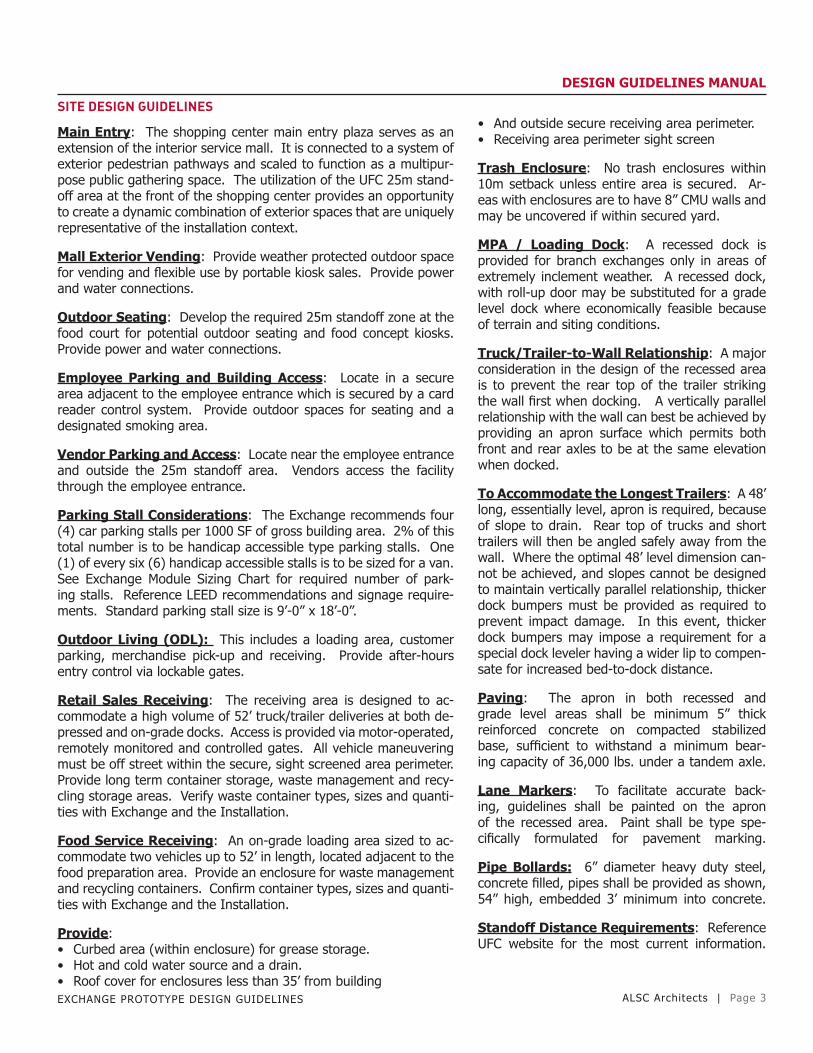
Main Entry: The shopping center main entry plaza serves as an extension of the interior service mall. It is connected to a system of exterior pedestrian pathways and scaled to function as a multipur-pose public gathering space. The utilization of the UFC 25m stand-off area at the front of the shopping center provides an opportunity to create a dynamic combination of exterior spaces that are uniquely representative of the installation context.
Mall Exterior Vending: Provide weather protected outdoor space for vending and flexible use by portable kiosk sales. Provide power and water connections.
Outdoor Seating: Develop the required 25m standoff zone at the food court for potential outdoor seating and food concept kiosks. Provide power and water connections.
Employee Parking and Building Access: Locate in a secure area adjacent to the employee entrance which is secured by a card reader control system. Provide outdoor spaces for seating and a designated smoking area.
Vendor Parking and Access: Locate near the employee entrance and outside the 25m standoff area. Vendors access the facility through the employee entrance.
Parking Stall Considerations: The Exchange recommends four (4) car parking stalls per 1000 SF of gross building area. 2% of this total number is to be handicap accessible type parking stalls. One (1) of every six (6) handicap accessible stalls is to be sized for a van. See Exchange Module Sizing Chart for required number of park-ing stalls. Reference LEED recommendations and signage require-ments. Standard parking stall size is 9’-0” x 18’-0”.
Outdoor Living (ODL): This includes a loading area, customer parking, merchandise pick-up and receiving. Provide after-hours entry control via lockable gates.
Retail Sales Receiving: The receiving area is designed to ac-commodate a high volume of 52’ truck/trailer deliveries at both de-pressed and on-grade docks. Access is provided via motor-operated, remotely monitored and controlled gates. All vehicle maneuvering must be off street within the secure, sight screened area perimeter. Provide long term container storage, waste management and recy-cling storage areas. Verify waste container types, sizes and quanti-ties with Exchange and the Installation.
Food Service Receiving: An on-grade loading area sized to ac-commodate two vehicles up to 52’ in length, located adjacent to the food preparation area. Provide an enclosure for waste management and recycling containers. Confirm container types, sizes and quanti-ties with Exchange and the Installation.
Provide:• Curbed area (within enclosure) for grease storage.• Hot and cold water source and a drain.• Roof cover for enclosures less than 35’ from building
• And outside secure receiving area perimeter.• Receiving area perimeter sight screen
Trash Enclosure: No trash enclosures within 10m setback unless entire area is secured. Ar-eas with enclosures are to have 8” CMU walls and may be uncovered if within secured yard.
MPA / Loading Dock: A recessed dock is provided for branch exchanges only in areas of extremely inclement weather. A recessed dock, with roll-up door may be substituted for a grade level dock where economically feasible because of terrain and siting conditions.
Truck/Trailer-to-Wall Relationship: A major consideration in the design of the recessed area is to prevent the rear top of the trailer striking the wall first when docking. A vertically parallel relationship with the wall can best be achieved by providing an apron surface which permits both front and rear axles to be at the same elevation when docked.
To Accommodate the Longest Trailers: A 48’ long, essentially level, apron is required, because of slope to drain. Rear top of trucks and short trailers will then be angled safely away from the wall. Where the optimal 48’ level dimension can-not be achieved, and slopes cannot be designed to maintain vertically parallel relationship, thicker dock bumpers must be provided as required to prevent impact damage. In this event, thicker dock bumpers may impose a requirement for a special dock leveler having a wider lip to compen-sate for increased bed-to-dock distance.
Paving: The apron in both recessed and grade level areas shall be minimum 5” thick reinforced concrete on compacted stabilized base, sufficient to withstand a minimum bear-ing capacity of 36,000 lbs. under a tandem axle.
Lane Markers: To facilitate accurate back-ing, guidelines shall be painted on the apron of the recessed area. Paint shall be type spe-cifically formulated for pavement marking.
Pipe Bollards: 6” diameter heavy duty steel, concrete filled, pipes shall be provided as shown, 54” high, embedded 3’ minimum into concrete.
Standoff Distance Requirements: Reference UFC website for the most current information.

EXCHANGE PROTOTYPE DESIGN GUIDELINES ALSC Architects | Page 4
DESIGN GUIDELINES MANUAL
EXTERIOR BUILDINGDESIGN GUIDELINES

EXCHANGE PROTOTYPE DESIGN GUIDELINES ALSC Architects | Page 5
DESIGN GUIDELINES MANUAL
EXTERIOR BUILDING DESIGN GUIDELINES
GENERAL:
Sizing Matrix: the below matrix is the module classifications for both new construction and existing facilities, and are categorized according to the below standards.
SHOPPING CENTER SIZINGMODULE SIZE TOTAL S.F.
2.0 271,083
3.0 223,759
4.0 168,019
5.0 132,419
6.0 99,879
7.0 72,815
8.0 40,792 The facility shall have an independent framing system, meaning, non-load bearing walls. Load-bearing wall systems will be used only when it can be economically justified, taking future expansion into consideration.
Skylights shall be located to fit between joists. Use stock size and configuration skylight units due to cost, availability, and speed of construction.
Provide canopy coverage at all regularly used entrances / loading doors, etc. Canopy coverage is not required at emergency exit doors. Canopies are not required at utility room entrances, but are recommended at the stairs, and main electrical and mechanical rooms.
Preferred insulation is polyisocyanurate, thickness as required to achieve the required thermal resistance.
The satellite dish is EF/EI. This includes cabling, the dish frame, and the dish itself.
Roof penetrations and weather head for running of dish cabling are CF/CI.
The front face of the ODL should align with the front face of the building for maximum visibility and accessibility to customers.
Exterior Accessories: Exterior trash cans, benches and smoke stacks are authorized for customer convenience depending on base guidelines and restriction.
Roof: The facility shall have an independent framing system, meaning, non-load bearing walls. Load bearing wall systems will be used only when it can be economically justified, taking future expansion into consideration.
Minimum roof slope shall be 1/2” / ft. Lower slope is acceptable at valleys, but in no case shall the roof slope be less than 1/4”/ft.
Roof drains at perimeter walls shall have a piped main drain with overflow scuppers. Internal drainage shall be double-piped mains and over-flows. Drains may be placed anywhere along the valley to coordinate with the building structure and spaces below. Consider that drains will be exposed in the retail sales area.
A single manufacturer shall supply roofing, walk pads, and accessories.
Factory mutual I-90 rating for resistance to wind up-lift must be met.
Preferred roofing is 60mil EPDM. The membrane may be mechanically fastened, or fully adhered. If a fully adhered membrane is to be used, scrim reinforcing of the membrane may be eliminated. Mechanically attached membranes must be scrim reinforced.
Folded plates are used as the main drainage con-cept. The roof structure is sloped to achieve the folded plates.
Over the mall a center ridge is used to provide architectural flexibility in the mall corridor. Other framing opportunities may be available here, de-pending on mall architecture.
Drain locations are flexible along valleys.
Tapered insulation is used to slope to drains in the valleys.
Warped planes are used at the ends of the mall ridge to bring the roof elevation to a level line at the parapet.
Slope = 1/2”/ft. at main building.Minimum height of parapet wall = 24’Number of drains: 16 internal, 4 perimeterAverage column height: 18’Wall surface area = 37,268 sf
EXCHANGE PROTOTYPE DESIGN GUIDELINES ALSC Architects | Page 6
DESIGN GUIDELINES MANUAL
INTERIOR BUILDINGDESIGN GUIDELINES

EXCHANGE PROTOTYPE DESIGN GUIDELINES ALSC Architects | Page 7
DESIGN GUIDELINES MANUAL
INTERIOR BUILDING DESIGN GUIDELINES
GENERAL:
Paint exposed structure in all areas where the structure is exposed to customer view, or in a retail space.
Paint all ceiling items including HVAC, electrical items the same col-or. See the finish legend for specific color of the ceiling.
Structure shall not be painted where it is not visible to customers.
Exposed structure shall occur in all MPA areas, and utility areas such as stairs, electrical rooms, mechanical rooms, etc.
Ceiling Heights: General guidelines are as follows:
Main Store Sales Area: 14’-0”Customer Service Area: 9’-0”Offices/Conference Rooms/Cashier’s Area/Toilet Rooms/ Break Rooms: 8’-0” to 9’-0” depending on room sizeMall Concepts: 10’-0”Food Concepts/Kitchen: 10’-0”
The main entry, the entry to the retail sales area from the mall, and the retail sales floor ‘V’, must be on the same centerline.
The enclosed / heated ODL must be connected to the retail sales area, and the connection must align with the power aisle.
Connections between building areas must be made according to the connection diagrams on drawing sheet A-101.
Refer to the building expandability diagrams for direction on how to expand / contract the individual areas of the building for various module combinations.
Communications: A single integrated system, that includes: tele-phone, paging, exchange radio, and customer call boxes should be specified. Contact IS-P for information. System is EF/EI.
Phone Outlets: should be included in the break rooms and MPA.
Review all Functional Areas: for communications systems, RPOS computer cables, internet capability, phones, and electrical requirements.
Optional: include TV equipment / fixtures as required for employee break rooms.
Stairs:• Stairs shall be steel with steel grating treads.• Roof hatch size and location should be coordinated with stair.• Safety up post, or guardrails should be provided with roof hatch.• A full stair to the roof is preferred for maintenance purposes.
• Access to the stair room should be only from the outside. Installation CE should have a key to the stair door.
• Area under stairs should have a method of ac-cess, or be closed off to prevent collection of debris under the stairs.
Mechanical – Electrical Rooms:Mechanical and electrical rooms must have exte-rior entrance only.
These rooms have no ceilings and are open to the structure above, do not paint.
Plywood wainscot should be installed on all walls to minimum 8’-0” AFF, to facilitate attachment of mechanical and electrical devices at any location in the room. Plywood should be fire resistant.
Keys to these rooms should be supplied to the installation.
Verify room sizes with actual mechanical and electrical requirements.
Janitor Rooms:Minimum size is 70 S.F., more if space allows. Provide sufficient space to hang mops & brooms, store cleaning supplies and miscellaneous items.
Provide a mop / broom holder on wall over sink, provide a shelf above the mop holder.
Provide a 36” x 36” floor sink.
Walls adjacent to the mop sink should be protect-ed from impact damage of wheeled mop buckets, etc. Sheet stainless steel or other impact resis-tant material is recommended on these walls and the wall area immediately above the sink.
Convenience outlets should be provided on at least two walls.
A ceiling is not required in the janitor’s room. If the room is left open to structure above, walls will need to be finished and painted all the way to the roof deck. In some cases a suspended ceiling may be preferred to open structure.

EXCHANGE PROTOTYPE DESIGN GUIDELINES ALSC Architects | Page 8
DESIGN GUIDELINES MANUAL
MALL
EXCHANGE PROTOTYPE DESIGN GUIDELINES ALSC Architects | Page 9
DESIGN GUIDELINES MANUAL
MALL DESIGN GUIDELINES
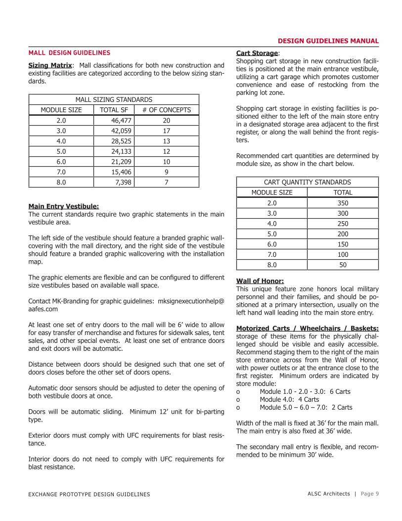
Sizing Matrix: Mall classifications for both new construction and existing facilities are categorized according to the below sizing stan-dards.
MALL SIZING STANDARDS
MODULE SIZE TOTAL SF # OF CONCEPTS
2.0 46,477 20
3.0 42,059 17
4.0 28,525 13
5.0 24,133 12
6.0 21,209 10
7.0 15,406 9
8.0 7,398 7
Main Entry Vestibule:The current standards require two graphic statements in the main vestibule area.
The left side of the vestibule should feature a branded graphic wall-covering with the mall directory, and the right side of the vestibule should feature a branded graphic wallcovering with the installation map.
The graphic elements are flexible and can be configured to different size vestibules based on available wall space.
Contact MK-Branding for graphic guidelines: [email protected]
At least one set of entry doors to the mall will be 6’ wide to allow for easy transfer of merchandise and fixtures for sidewalk sales, tent sales, and other special events. At least one set of entrance doors and exit doors will be automatic.
Distance between doors should be designed such that one set of doors closes before the other set of doors opens.
Automatic door sensors should be adjusted to deter the opening of both vestibule doors at once.
Doors will be automatic sliding. Minimum 12’ unit for bi-parting type.
Exterior doors must comply with UFC requirements for blast resis-tance.
Interior doors do not need to comply with UFC requirements for blast resistance.
Cart Storage:Shopping cart storage in new construction facili-ties is positioned at the main entrance vestibule, utilizing a cart garage which promotes customer convenience and ease of restocking from the parking lot zone.
Shopping cart storage in existing facilities is po-sitioned either to the left of the main store entry in a designated storage area adjacent to the first register, or along the wall behind the front regis-ters.
Recommended cart quantities are determined by module size, as show in the chart below.
CART QUANTITY STANDARDS
MODULE SIZE TOTAL
2.0 350
3.0 300
4.0 250
5.0 200
6.0 150
7.0 100
8.0 50
Wall of Honor:This unique feature zone honors local military personnel and their families, and should be po-sitioned at a primary intersection, usually on the left hand wall leading into the main store entry.
Motorized Carts / Wheelchairs / Baskets: storage of these items for the physically chal-lenged should be visible and easily accessible. Recommend staging them to the right of the main store entrance across from the Wall of Honor, with power outlets or at the entrance close to the first register. Minimum orders are indicated by store module:o Module 1.0 - 2.0 - 3.0: 6 Cartso Module 4.0: 4 Cartso Module 5.0 – 6.0 – 7.0: 2 Carts
Width of the mall is fixed at 36’ for the main mall. The main entry is also fixed at 36’ wide.
The secondary mall entry is flexible, and recom-mended to be minimum 30’ wide.
EXCHANGE PROTOTYPE DESIGN GUIDELINES ALSC Architects | Page 10
DESIGN GUIDELINES MANUALMALL DESIGN GUIDELINES
All mall signage will be coordinated with HQ/SD-M2.
The employee entrance is to be lockable from both inside and out-side. All other doors are to be locked from the inside.
Height of the mall is to be 14’ minimum to allow for mall signage, portals, and hanging banners.
Portals: portals are installed at all service / commodities busi-nesses. The intent of the portal is to identify tenant storefronts along each concourse. Reference drawing sheet MA-A05 for details and information. Portals are CF/CI.
Optional Retail Commodity Niche: the retail niche element is used as an alternate to a wall kiosk for vendor merchandising where large expansive areas of wall are available. The element comple-ments the standard tenant storefront portal design and utilizes a modular display wall system to allow for merchandising flexibilities. Portal Frame is CF/CI and modular wall system is EF/EI.
Optional Vending Niche:The vending niche is used to contain and unify a diverse collection of vending units. The element utilizes the portal design to mimic a standard tenant storefront. When used, it should be positioned on the non-food court concourse.
The portal frame is CF/CI.
Provide power outlets to support vending machines.
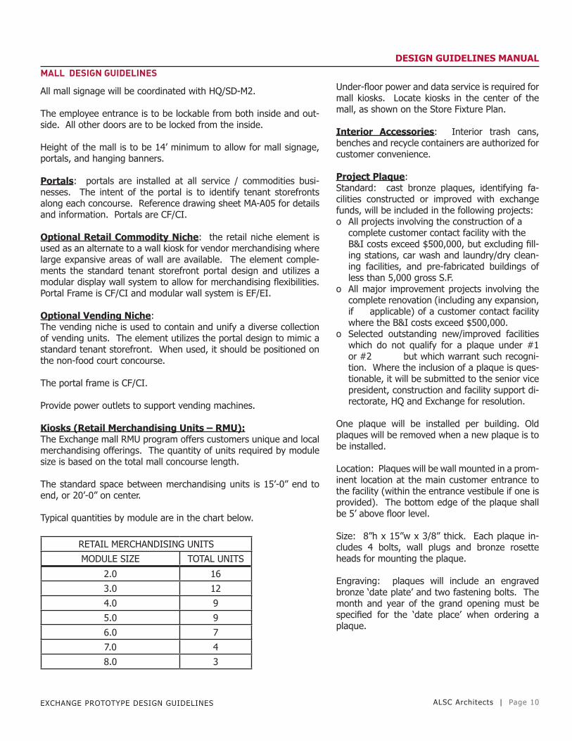
Kiosks (Retail Merchandising Units – RMU):The Exchange mall RMU program offers customers unique and local merchandising offerings. The quantity of units required by module size is based on the total mall concourse length.
The standard space between merchandising units is 15’-0” end to end, or 20’-0” on center.
Typical quantities by module are in the chart below.
RETAIL MERCHANDISING UNITS
MODULE SIZE TOTAL UNITS
2.0 16
3.0 12
4.0 9
5.0 9
6.0 7
7.0 4
8.0 3
Under-floor power and data service is required for mall kiosks. Locate kiosks in the center of the mall, as shown on the Store Fixture Plan.
Interior Accessories: Interior trash cans, benches and recycle containers are authorized for customer convenience.
Project Plaque:Standard: cast bronze plaques, identifying fa-cilities constructed or improved with exchange funds, will be included in the following projects:o All projects involving the construction of a
complete customer contact facility with the B&I costs exceed $500,000, but excluding fill-ing stations, car wash and laundry/dry clean-ing facilities, and pre-fabricated buildings of less than 5,000 gross S.F.
o All major improvement projects involving the complete renovation (including any expansion, if applicable) of a customer contact facility where the B&I costs exceed $500,000.
o Selected outstanding new/improved facilities which do not qualify for a plaque under #1 or #2 but which warrant such recogni-tion. Where the inclusion of a plaque is ques-tionable, it will be submitted to the senior vice president, construction and facility support di-rectorate, HQ and Exchange for resolution.
One plaque will be installed per building. Old plaques will be removed when a new plaque is to be installed.
Location: Plaques will be wall mounted in a prom-inent location at the main customer entrance to the facility (within the entrance vestibule if one is provided). The bottom edge of the plaque shall be 5’ above floor level.
Size: 8”h x 15”w x 3/8” thick. Each plaque in-cludes 4 bolts, wall plugs and bronze rosette heads for mounting the plaque.
Engraving: plaques will include an engraved bronze ‘date plate’ and two fastening bolts. The month and year of the grand opening must be specified for the ‘date place’ when ordering a plaque.

EXCHANGE PROTOTYPE DESIGN GUIDELINES ALSC Architects | Page 11
DESIGN GUIDELINES MANUAL
MALL DESIGN GUIDELINES
Surveillance - Security:Requests to procure / install EVSS in exchange facilities should be forwarded through the region loss prevention official for coordina-tion with HQ-LP prior to action by the region director. HQ-LP will arrange for an on-site survey by the EVSS vendor through PZ-S as part of the coordination process.
Employee Entrance: Install a security camera at the employee entrance. Also install one electric button activating and controlling access to the employees’ entrance door. Locate the button at the receptionist’s desk. Two-way audio/visual communication and moni-toring will be required at both locations. At locations where EVSS is utilized, a camera should be placed at the back door so entry can be monitored and filmed if warranted.
The security office is to be in the mall area no further than 50 feet from the main entrance of the store but not immediately adjacent to the entrance.
The security office is to be minimum 200 SF, with half the space de-voted to monitors and equipment, and the other half for interviews and detention.
Some functions of the system in the surveillance room are to be du-plicated in the facility manager’s office, such as the remote control console / rack, box keyboard and 17” call-up monitor.
Surveillance equipment is AF/AI.
•Lighting: Provide one fluorescent light fixture, switched indepen-dently from the lighting in the security office. Provide one incan-descent downlight (100w r40 flood) directly above console operator, equipped with a dimmer switch.
Provide adequate ventilation / cooling to offset heat generated from EVSS equipment. Heat load = 12,000 BTU/H.
Pharmacy:Placement of a pharmacy within the mall is recommended provided it complies with the following guidelines:
Pharmacy will be located inside the mall as per approved module layout. Size of the pharmacy may vary based on demographics; however, it should be placed between the secondary entrance and beauty or barber shop.
A centrally-located military pharmacy is encouraged in the malls. Space may be allocated through new construction or renovation of existing space. The senior exchange official on an installation should coordinate with exchange PL/P.
Costs associated with military pharmacies in malls or other exchange facilities must be reimburs-able. This includes, but is not limited to, costs associated with new construction or renovation, monthly utility usage (if separate utility meters are not available) or other rendered services which may apply to pharmacy operations. The written MOU must include the reimbursable de-tails. It is preferable that a separate utility meter and alarm system be installed through appropri-ated funds (AFP).
Only one non-exchange activity is authorized space inside the mall. Requests for exception must be forwarded to COO for review / approval.
EXCHANGE PROTOTYPE DESIGN GUIDELINES ALSC Architects | Page 12
DESIGN GUIDELINES MANUAL
FOOD COURTDINING ROOM

EXCHANGE PROTOTYPE DESIGN GUIDELINES ALSC Architects | Page 13
DESIGN GUIDELINES MANUAL
FOOD COURT - DINING ROOM DESIGN GUIDELINES
All module sizes require a separate food court entrance direct to the dining and restaurant area.
Food court classification for both new construction and existing fa-cilities are categorized according to the below sizing standards:
FOOD COURT SIZING
MODULE SIZE SEAT COUNT SF# OF
CONCEPTS
2.0 358 16,570 6
3.0 308 16,160 6
4.0 264 12,045 5
5.0 218 11,132 5
6.0 210 9,725 4
7.0 192 8,965 3
8.0 80 1,080 2
Dining Room Layout:The current standard for dining room furniture utilizes a variety of seating types and three table finish standards to create separate areas for dining. Dining Room furniture is EF/EI.
Dining Room furniture is a combination of booths. 2-top tables and 4-top tables. Food standard is 75% 2-top tables and 25% 4-top tables. Booths should be used based on space available. A percent-age of 4-top tables will be handicap accessible based on current ADA accessibility guidelines for total seating capacity.
Dining Room seating layouts are provided by Seating Concepts on a per project basis. Coordinate with the Exchange Project Manager for additional information.
Food Court Video Tower: the elliptical TV tower provides identity to the food court and offers an electronic charging area with bar style seating. The tower features four 55” television monitors to display news, announcements, promotions and other video content.
Food Court Graphics:
Perimeter Wall: one wall of the dining room should feature a brand-ed graphic wallpaper. The elements are flexible and can be config-ured to different dining room sizes based on available wall space. Contact MK-Branding for graphic guidelines: [email protected]
Bulkhead Soffit: The ceiling above the food concepts or dining room area should have a bulkhead soffit to display the “CityScape” graphic wallpaper. The element is flexible and can be configured to dif-ferent dining room sizes based on available wall space. Contact
MK-Branding for graphic guidelines: [email protected]

EXCHANGE PROTOTYPE DESIGN GUIDELINES ALSC Architects | Page 14
DESIGN GUIDELINES MANUAL
FOOD COURT KITCHEN(BACK OF HOUSE)

EXCHANGE PROTOTYPE DESIGN GUIDELINES ALSC Architects | Page 15
DESIGN GUIDELINES MANUAL
FOOD COURT KITCHEN (BACK OF HOUSE) DESIGN GUIDELINES
Reference individual Food Concept Drawings for specific concept in-formation.
All ceilings in the food court back of house and food concepts are to be washable.
Employee toilet and locker room ceilings are to be washable.
Walls between food concepts are not required to be to structure above.
Walls between seating area and food concepts or back of house will extend to the roof deck above.
The guidance below is provided for support / kitchen / administra-tion design for all food court locations to develop architectural layout and design.
Combined brands in one food court operation must take into con-sideration the type of food being prepared. Under the guidance of the FDA code and TBMED 530, all areas of preparation must identify preparation and storage of potentially hazardous foods to decrease food cross contamination.
Walk-in Coolers and FreezersSupplier = walk-in cooler/freezer unit supplier.
GC (General Contractor) = the general contractor or any of his sub-contractors.
Electrical:Supplier will provide electrical load requirements and circuit breaker sizes to architect or engineer.
Panels and circuit breakers will be provided and installed by the general contractor.
Branch circuit conduit and wiring from the GC-furnished panel will be furnished and installed by supplier.
Final electrical terminations to all equipment related to the walk-in cooler/freezer will be made by the supplier.
Disconnects for all condensing units will be provided by the supplier.
Plumbing:Floor drains outside of each walk-in unit for evaporator condensate water will be provided and installed by the general contractor.
Drain lines from the cooler unit to the floor drains will be installed by the supplier.
General Requirements:Clearance of 2” shall be provided around all sides of the walk-in, between the box and any adjacent construction. There should be adequate clear-ance above the ceiling of the walk-in for installa-tion and servicing.
A level, trowel-finished floor, with a moisture bar-rier is required under the walk-in.
Condensing units must be located within 50’ of their respective walk-in boxes.
A pad for condensing units shall be furnished and installed by the contractor when the con-densing units are mounted at ground level. The pads should allow 3’ of clearance around each condensing unit for adequate air flow and main-tenance access. Provide one 4” hole for Freon lines and one 1-1/2” hole for electrical lines in the exterior wall of the building at each condensing unit.
Roof mounted condensing units: roof supports and any structural steel roof reinforcement shall be supplied by the general contractor when con-densing units are mounted on the roof. Roof pen-etrations for Freon lines, electrical lines and pitch pans shall be CF/CI. Sealing of all roof penetra-tions is by general contractor.
Penetrations in the building and sealing of pen-etrations are by general contractor. All penetra-tions made in the walk-in system for sprinklers or other items not related to the operation of the walk-in shall be made and sealed by the contrac-tor.
Installation of walk-in shall include assembly of the box with associated equipment, including shelving, when furnished by TMP, refrigeration lines, electrical, and plumbing as specified above.
Walk-in cooler / freezer supplier is:
Cuff/Moreland, Inc.PO box 570833Dallas, TX, 75357-0833email: [email protected]: 972-681-4541fx: 972-681-4542Contact: Maryann Moreland

EXCHANGE PROTOTYPE DESIGN GUIDELINES ALSC Architects | Page 16
DESIGN GUIDELINES MANUAL
FOOD COURT KITCHEN (BACK OF HOUSE) DESIGN GUIDELINES
Chicken (Popeye’s, Church’s):A dedicated walk-in cooler for tempering and storage of poultry items - no exceptions.
Flooring finish inside the cooler will be porcelain tile to ensure proper cleaning.
Draining of blood must comply with applicable environmental laws.
Seafood: Requires a dedicated walk-in cooler for tempering or storing of fish or shellfish.
General Kitchen (Back of House) Equipment:
3-compartment sinks: Provide one 3-comp. Sink for every two-clus-ter concepts. Drain boards left and right. The flow of washing is generally left to right; the left drain board therefore receiving the dirty dishes / pans. This is located away from sanitary stations / equipment (i.e. prep tables, ice makers). Booster heaters are not required. A chemical sanitation process will be used.
Metro Smartwall: will be located above each 1, and 3-compartment sinks.
Dishwashing Unit: Should include a garbage disposal placed on the entry point and 2-4 foot dry shelf at exit. Configuration will be based on layout and flow of dishwashing procedures.
Pot / pan racks: One for each cluster concept of sufficient size to fit within the available space. Racks are portable, with s/s slotted shelves. If lack of space prohibits racks, identify pot / pan holders above each 1 and 3-compartment sinks.
Work tables: 6’ long x 30” deep table with drawer and overshelf for each cluster. This may vary depending on the brand. Provide one per concept. Standard equipment packages identify worktables, however, common kitchen preparation areas will need additional work tables to fit layout. Specify with casters and 6’ long cords to facilitate cleaning.
Handwash sink: One for every food brand identified. Use smaller type to discourage use for pan washing. Specify touchless opera-tion. CF/CI.
Ice machine: One 1,000 lb capacity machine. Mount condensing unit on roof if practical. Built-in condensing units are acceptable where no space is available for remote units. Filtration system is required for the ice machine water supply.
Reach-in refrigerators: One double door for each concept. Do not specify 3-door refrigerators. Specify casters and 6’ long cords to facilitate cleaning.
Reach-in freezers: One single door for each con-cept. Specify casters and 6’ long cords to facili-tate cleaning.
Trash receptacle: One for each concept, and one at each sink.
Portable bus carts: To be determined by brand(s).
Shelving units: Two (2) s/s 4’ wide x 18” deep wire storage shelving for each concept.
Soda system: Locate in isolated and possibly en-closed area, minimize heat dissipation and hide unsightly equipment, product lines, etc., exhaust-ed by a ceiling fan. Use judgment when locating (length of lines to service drink stand, etc.,) try to keep runs of lines under 75’. Area need not be fully enclosed; no door needed, and should be readily accessible to product suppliers.
Co2: Bulk is preferred over individual bottles. Refill connectors should be placed on the exterior if feasible. Check if refilling is available on your installation.
Drink stations: Locate on perimeter wall of food concepts or in dining room space. When in lo-cated in dining room space, do not impede circu-lation or view of concepts. Where ceiling space allows, provide ice makers for each drink station. Ice makers should have integrated condensers, and not remote located.
Receiving area: Door should be wide enough to accommodate a full size pallet for ease of deliv-ery. Provide ample space for short-term storage as supplies are delivered. Make at least 10’ wide to accommodate shelving against the side walls. Include a trash receptacle and a portable cart.
Delivery doors: Should be wide enough for a standard size pallet to facilitate product delivery.
Delivery dock: Should be considered to assist in off-loading food products. Do not include if grad-ing and space does not allow.
The above represents basic requirements for the support space. During the programming stage adequate sizing should be established for these areas. However, shared chill space must not violate poultry and seafood requirements noted above.
EXCHANGE PROTOTYPE DESIGN GUIDELINES ALSC Architects | Page 17
DESIGN GUIDELINES MANUAL
FOOD COURT KITCHEN (BACK OF HOUSE) DESIGN GUIDELINES
Any non-standard plan not approved by Exchange corporate brands must be sent to SD/F and HQ staff for full review.
Employee Break / Training Room:Size is determined by the number of concepts and employees. Pro-vide sufficient space to use as a training area.
Provide sound insulation in surrounding walls.
Size based on module square footage:o 35K – 175 S.F.o 45K & 65K – 200 S.F.o 95K – 225 S.F.o 145K – 250 S.F.
Staff Toilet / Locker Rooms:Provide one for men and one for women, single usage. Overseas must abide by local laws for amounts.
Locate access separate from break room.
Restrooms should share a common wet wall.
Lockers are EF/CI.
Locker rooms are not for changing, but are for storage of employees’ personal items during work hours.
Provide sound insulation in surrounding walls.
Storage:The storage room is also a possible location for a water heater serv-ing the food court area.
Provide shelving in the storage room if a water heater is not located there.
Office:Provide (1) office for General Food Court Manager, and (1) shared office to accommodate managers for each Food Concept. Shared office must have power and data available for computer stations for each of the food concept managers.
Consider the use of modular furniture. All furnishings are EF/EI.
Provide sound insulation in all surrounding walls.
Provide a vision panel in the door, or a window for sight connection to the back of house area.

EXCHANGE PROTOTYPE DESIGN GUIDELINES ALSC Architects | Page 18
DESIGN GUIDELINES MANUAL
PUBLIC TOILET ROOMS

EXCHANGE PROTOTYPE DESIGN GUIDELINES ALSC Architects | Page 19
DESIGN GUIDELINES MANUAL
PUBLIC TOILET ROOMS DESIGN GUIDELINESComply with IBC and ADA for toilet room design.
Retail mall up to 50,000 SF (Modules 6.0 - 7.0) - one set of rest-rooms located in the mall.
Retail mall over 50,000 SF (Modules 1.0 – 5.0), two sets of rest-rooms, one located in the mall near or adjacent to the food court, one located adjacent to the Admin area, and accessible from main Retail Sales floor.
Entries into toilet rooms will be similar to ‘airport style’ to provide easy access to disabled customers.
Restrooms are identified with a branded graphic wallpaper to help customers find where they are going quickly. The graphics are flex-ible and can be configured to different size malls based on available wall space. Contact MK-Branding for graphic guidelines: [email protected]
Benches are recommended to be placed outside the mall restrooms – EF/EI.
All modules will contain one Family Style unisex restroom located directly adjacent to the main toilet rooms in the mall.
Diaper changing station and an adjacent disposal unit for diapers will be included in restrooms - CF/CI. Mount the top ledge of the changing table at 32” A.F.F., designed to hold 250 lbs. Do not include the changing station within any toilet stall. Provide two extra sets of safety straps and four extra cases of bed liners.
Child safety seats from Koala will be installed in all accessible stalls in all restrooms, designed to hold 150 lbs. Safety seats will be mounted on walls and not on stall partition. Provide two extra sets of safety straps - CF/CI.
Toilet / urinal partitions should be solid plastic in all toilet rooms - CF/CI.
Automatic touch-less paper towel dispensers will be standard in all restrooms - CF/CI.
Men’s urinals will be wall-mount type with in-wall steel supports.
A lower urinal will be included in the men’s restroom for children. Dividers will be used between urinals, made of the same material as the stall partitions
Tampon dispensers are not required in women’s restrooms.
Large toilet paper dispensers should be used in the public and em-ployee toilet rooms to reduce maintenance - CF/CI.
Adequate ventilation will be provided in all restrooms. The exhaust fan in the larger customer and employee restrooms shall be inter-locked to the HVAC system. The CFM capacity of the exhaust shall
be based on ASHRAE minimum requirements. The exhaust fan in the smaller customer and employee restrooms or restrooms remote from the HVAC system shall be switched with the light switch.
FMO projects to retrofit existing facilities may either switch the exhaust fan with the light or separate, whichever is most cost-effective based on the re-wiring that would need to be accom-plished.
Floor drains will be installed in all restrooms for ease of cleaning and containing spills.
Lights within the restroom will be sensor oper-ated to turn off after 5 minutes. The sensor for the rest of the room will be located in the entry to ensure that the lights are on before the customer enters the restroom.
Built-in vending machines will not be included.
A wall mounted, semi-recessed trash receptacle will be located directly adjacent to the paper tow-el dispenser - EF/EI.
Stalls will include a hook, a small spring-loaded shelf, seat protectors, and large toilet paper dis-pensers for 18” rolls. Ladies restrooms will also include a sanitary disposal unit - CF/CI.
Soap dispensers will be wall-mounted and use liq-uid soap, mount at 38” A.F.F. - EF/CI.
Small shelves with hooks under, will be installed over the hand blower and paper towels to hold customer bags/purses/etc., and mounted high enough so as not to become wet from the sink. Mount at 38” A.F.F. - CF/CI.
Speakers, EF/CI, will be included in all restrooms for music and paging from the main store.
Large mirrors will be included over each lavatory - CF/CI.
A full length mirror will be included in each re-stroom. Install 3-5 hooks near the mirror to ac-commodate additional hanging requirements, I.E., coats, etc. Mirror and hooks shall be located within the restroom, near the entry. Mirror and hooks – CF/CI.
Ceilings throughout toilet rooms will be washable.
EXCHANGE PROTOTYPE DESIGN GUIDELINES ALSC Architects | Page 20
DESIGN GUIDELINES MANUAL
RETAIL SALES

EXCHANGE PROTOTYPE DESIGN GUIDELINES ALSC Architects | Page 21
DESIGN GUIDELINES MANUAL
RETAIL SALES DESIGN GUIDELINESStained / polished concrete is the standard for new construction.
VCT tile can be optional for expansions, resets, or renovations by exception only. Contact RE-P for approval.
Retail area shall have exposed structure, painted. Design HVAC, lights, conduits, and other ceiling mounted devices for orderly, or-ganized appearance.
In renovation projects, the decision to provide a ceiling in the retail sales area will be based on the condition of the existing structure that will be exposed, the condition of the mechanical and electrical items that will be exposed, and the cost associated with changing them to be visually acceptable in customer areas
Cornice lighting is to be used along the perimeter wall in softlines only.
Wall-wash lighting along perimeter walls in softlines is acceptable for existing stores.
Columns in hardlines and softlines are to be square steel beam with minimum dimensions, prepped and painted. All columns will have electrical dual outlets. Some columns will also be equipped with phone lines. Columns are not to be furred out.
Metal sign grid: A metal grid is mounted to the perimeter wall of the main store. The top of the grid will be at 14’-0”. The grid al-lows seasonal signs and other graphics to be hung in an overlapping manner around the store.
Fire doors, to include those in the MPA will be equipped with local alarm, and panic bar for ease of opening during operational hours.
Facility master key system: the system should allow one key for the front gate, stockroom door and employee entrance from both inside and outside. The system should allow a master key for all other doors that can be keyed to allow lower level access such as to a janitor closet.
Communications: A single integrated system that includes tele-phone, paging, exchange radio, and customer call boxes should be specified, EF/EI. System selected to allow for pages to specific areas of the store only. It should have ‘smart sound’ which automatically adjusts the system volume to account for noise levels.
Power poles will be used in all departments as needed. Color is to match Wilsonart laminate frosty white #1573-60, or can be painted to closely match the color.
Central checkouts will use power poles.
Review all functional areas for communications systems, RPOS computer cables, internet capabil-ity, phones and electrical requirements. Include TV equipment / fixtures a required for employee break rooms.
Call boxes and price check stations: These will be installed in all main store renovations and new construction. Placement of these boxes should be at critical areas such as the Powerzone, self-service departments and softlines. Layout should be determined in the planning stages. The num-ber of call boxes and price check stations are de-termined by the sales floor square footage
MODULE
CALL BOXES HARD-LINES
CALL BOXES SOFT-LINES
PRICE CHECK
STATIONS
1.0 4 4 8
2.0 4 4 8
3.0, 4.0, 5.0 3 3 6
6.0, 7.0 2 2 4Call boxes and price check stations will be located on columns throughout the facility. At a mini-mum, the following departments must have the call boxes and price checks stations and based on the module size the quantities will vary: outdoor living, furniture, cosmetics, Powerzone, women’s, men’s, children’s, HBC, and housewares. Call boxes are to be mounted no higher than 54” above finished floor.
Interior wall projections that would interfere with store fixtures or shelving shall be kept to a mini-mum.
Dressing rooms: Are modular units that will con-tain a bench, mirror, coat hooks and a trash con-tainer. Dressing rooms and accessories are EF/EI, and will be located as per the store fixture plan.
Powerzone:An electrical sub-panel should be dedicated to the Powerzone.
MPA for Powerzone should have a fenced area 10’ x 6’ for storage of sensitive items. No other fenc-ing is required in the MPA.
Electrical outlets with multiple sockets are to be made available in the electronics area in all gondolas and wall units. Add recessed electri-cal j-boxes (4” above finished floor at 12’ spacing along perimeter walls of retail sales area. Provide one electrical circuit for each four boxes.

EXCHANGE PROTOTYPE DESIGN GUIDELINES ALSC Architects | Page 22
DESIGN GUIDELINES MANUAL
RETAIL SALES DESIGN GUIDELINES
Power poles may be dropped to fixtures to provide power.
Circuits serving the TV’s should be 20a, 120v. The TV’s should be limited to no more than 80% of the circuit rating, or 16 max. Amps on each 20a circuit. Usually no more than 3 or 4 TVs per circuit.
Cable system shall be installed to handle all display TV’s as well as display area at the front of the PZ. Contact local cable provider. EF/EI
Central Checkouts:Distance between register stands should be 36”. Include protective strips. Reference store fixture plan.
The distance from the wall to the register stands should be 10’ to allow cart storage space.
ADA: all main store modules will contain one checkout counter (po-co-a), to accommodate associates with disabilities.
Main stores with Pan Osten checkouts will position the ADA check-out (POCO-A) as the second closest to the main entrance. The first checkout (POCO-S) will be designated as the express lane. The primary register is in the direct line of sight of tobacco. The primary register is open all hours of operation.
Front end merchandisers (impulse racks) are available in three dif-ferent styles for main stores. These are snow white to match main store gondolas.
Use checkout lane lights in stores with 8 or more checkouts.
Use lane blockers in checkouts that are closed. The use of lane blockers is at the discretion of the store manager. Re has approved authorized lane blockers.
Carts:Cart rail (guardrail) is required if carts are positioned to the right side of the checkout closest to the entrance.
All carts are EF/EI.
Main store carts, model #1078 - large plastic gray cart are required. For stores that have checkouts with lanes at 36” or greater. Model #1071 - small plastic gray cart - will continue to be used for stores having checkout lanes less than 36” wide.
Stores 20k - minimum of 100 carts with 10% having infant cart seats. Child shopping carts are not authorized due to liability and safety risks.
Outdoor living carts: model #6000-20 from Reh-rig. (25.7 cu. Ft.). Minimum order will be re-quired according to store class
Five (5) outdoor living platform trucks from Reh-rig, model #3000-20 will be ordered for all stores with an outdoor living department.
Hand baskets: order a minimum of 96 for main stores - 8 sets with stands and signs.
Cart Rail:Floor mounted metal rail. Reference finish legend on sheet RS-A04.
Central Checkout Lane Lights:Standard: lane lights shall be provided at each register in the central checkout for main stores having a minimum of 8 registers.
Applicability: this standard applies to main store new construction or major renovation projects.
Description: the light boxes are white background with blue numbers. Lights are provided with a 6’ cord and grounded plug.
Vendor: moon international 1-800-356-7980

EXCHANGE PROTOTYPE DESIGN GUIDELINES ALSC Architects | Page 23
DESIGN GUIDELINES MANUAL
CUSTOMER SERVICE

EXCHANGE PROTOTYPE DESIGN GUIDELINES ALSC Architects | Page 24
DESIGN GUIDELINES MANUAL
CUSTOMER SERVICE DESIGN GUIDELINES
Cashier Cage: locate the cashier cage inside the customer service areas. Co-locate the counter / cashier windows with the customer service counter. Customer Service and Cash Office as per store fixture plan.
Sufficient electrical outlets must be provided to support cashier cage functions. Wire mold is a suggested option for increasing availability of outlets.
Ceiling: 9’-0” high, suspended acoustical panel.
Ventilation: 25cfm minimum for each cashier station.
Door: solid core wood door, storeroom lock, outside knob fixed en-trance by key only, inside knob always unlocked. Heavy duty hinges.
Counter: plastic-laminate, 42” above finished floor.
Foot rail: fabricated of 1-1/4” diameter satin finish chrome plated steel tubing. End plates are painted to match wall, and are attached with flush-head chrome plated screws.
Cashier pedestal: EF/EI – Mosler, Inc., pedestal is to be fabricated of steel with two box drawers, top drawer equipped with currency tray with cover and a storage compartment. Box drawers to be equipped with recessed pull (concealed latch) and paracentric keyed lock. The compartment is furnished with a single shelf, adjustable on 1/2” centers, a double-wall cabinet door hinged on right side, recessed door pull, magnetic catch and paracentric keyed lock. All locks on each unto to be keyed alike. Unit shall be furnished with a ‘velvet beige’ finish. 18-7/8” wide, 18-7/8” deep, 28” high. Alarm system: Money Clip, Walter Kidde model 630142 or equal. Provide one per cash drawer, with mating electric plug for easy re-moval of cash trays. Electric alarm signal connected to military-security police is activated when a pre-placed bill is removed from the clip. Duress alarm foot switch is of the joint services intrusion detection systems (JSIIDS) type.
Cash Vault:GSA requirements must be met for the vault. Vault is EF/EI.
Vault may be cast-in place, CMU, or pre-fabricated.
A 5- sided structure is required, with a secure roof panel.
Interior ceiling height should be 8’-0”.
A 40”w x 78” high GSA class 5 single-leaf vault door is included, CF/CI. Meet specification AA-D-600. Include a standard day-gate.
Slab under the vault should be 12” thick rein-forced concrete - CF/CI. The vault will sit directly on top of the slab.
1 HVAC access port shall be provided.
4 conduit penetrations for alarm, power, and data shall be provided.
Approximate weight of the vault, not including the floor slab is 24,000lbs. The door is estimated to weigh 1,500 lbs.

EXCHANGE PROTOTYPE DESIGN GUIDELINES ALSC Architects | Page 25
DESIGN GUIDELINES MANUAL
ODL(OUTDOOR LIVING)

EXCHANGE PROTOTYPE DESIGN GUIDELINES ALSC Architects | Page 26
DESIGN GUIDELINES MANUAL
ODL (OUTDOOR LIVING) DESIGN GUIDELINES
Exterior flooring will be concrete.
Enclosed ODL has no ceiling. Structure is exposed, and painted. The enclosed area is to have full height walls with a roll-up door on one wall and is to be heated.
The requirement for sunscreen covered area in the garden sales area is to be determined based on geographical and climatic influ-ences. 33% of the total outdoor living space is recommended to be under sunscreen cover. It is recommended that a zoned plant irriga-tion be system in installed in all warm climate areas.
Mass display plastic pallets will be used in the sunscreen area.
The customer pick-up entrance will be located at the side of the store, unless site restricted.
The outside area will consist of approximately 33% hardcover, 33% sunscreen, and 33% outside uncovered.
Fencing shall surround the sunscreen and uncovered areas. Micro-mesh is recommended in lieu of chain link. The screen fencing shall be a minimum of 10’ high, and the surface shall not allow easy toe-hold / hand-hold access over the top.
Adjust sunscreen area for local conditions. There is no requirement for separate areas to store chemicals of insecticides.
The register stand and the kiosk for the outdoor living area will be listed in the EF/EI fixture package. Facilities will order according to the size of their garden center and take into consideration demo-graphics, climate and length of the season. Kiosks must meet ADA requirements.
Exterior cash register stand will be placed next to the customer pick-up zone. It is EF/EIT.
The kiosk will also be positioned by the customer pick-up zone. The kiosk is EF/EI.
Provide power to both the cash register stand and the kiosk.
Screening chain link areas that are exposed to heavy traffic or sensi-tive areas should be considered.
Wall fixtures for the covered area will be 10’-0” high.
Floor gondolas will be 7’-0” high.
All bagged fertilizers and insecticides must be protected from rain. These products shall be kept in a central location which can be cov-ered easily by an awning. The awning will have an overhang wide enough to protect the merchandise from rain at a minimum.
Portable emergency eye-wash stations will be provided in ODL locations that receive or handle injurious corrosive chemicals - CF/CI.
Sales and Space Allocation:Final sizing will be based on the sales floor square footage, site location and overall requirements.
Site restrictions may determine the shape of the fenced-in ODL area.
Geographical location may increase or decrease space required for live plants and shrubbery.
Forklift operations: space should allow for forklift maneuvering, placement of kiosk, columns and poles should not disrupt the merchandise presen-tation.
Entrances and Exits:A buzzer shall be installed (CF/CI) at the pick-up area for customer use.
Entrance from the main store proper into the hardcover ODL area shall be an automatic sliding door. A 12’ bi-parting unit is preferred.
Security devices such as cameras, alarms, and scanners must comply with current security stan-dards and guidelines.
Locksets will be provided on all exterior doors as appropriate to door type and use, and to comply with current security standards.
Follow OSHA requirements for accessible ramps, emergency lighting and fire exits, etc.
Water and Drainage:The hanging plant area will include zoned irriga-tion sprinklers at approx. 12’ from the floor. The number of sprinklers will be determined by the actual size of the area. The plant irrigation sys-tem is EF/EI.
Plant misting system is EF/EI. Contractor is to provide a 3/4” water stub in the building wall ad-jacent to the sunscreen canopy with a shut-off valve for future connection to the misting system.

EXCHANGE PROTOTYPE DESIGN GUIDELINES ALSC Architects | Page 27
DESIGN GUIDELINES MANUAL
ODL (OUTDOOR LIVING) DESIGN GUIDELINES
Water faucets are required to accommodate watering plants and cleaning all other outside areas. Location and number will be based on the amount of square footage devoted to the area.
Floor and area drainage systems are required to accommodate wa-ter from irrigation system, building drains and roof drains, etc.
Electricity and Lights:
Weatherproof outlets need to accommodate registers, kiosk, buzzer, outdoor displays and security system.
Lights in this area to be photo sensitive to allow lights to turn on/off according to light levels at various times of day and seasons.

EXCHANGE PROTOTYPE DESIGN GUIDELINES ALSC Architects | Page 28
DESIGN GUIDELINES MANUAL
MC - MILITARY CLOTHING
EXCHANGE PROTOTYPE DESIGN GUIDELINES ALSC Architects | Page 29
DESIGN GUIDELINES MANUAL
MC - MILITARY CLOTHING DESIGN GUIDELINES
The current standard, positions MC – Military Clothing within the retail environment adjacent to the men’s department to encourage add on sales and utilize a shared receiving area with the main store.
Co-location inside a main store requires SVP/SD approval.
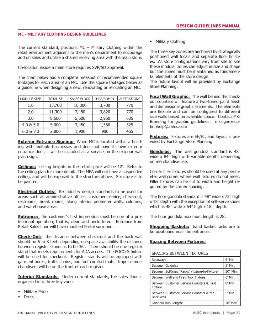
The chart below has a complete breakout of recommended square footages for each area of an MC. Use the square footages below as a guideline when designing a new, renovating or relocating an MC.
MODULE SIZE TOTAL SF SALES FLOOR MPA/ADMIN ALTERATIONS
1.0 13,700 10,000 3,700 770
2.0 11,300 7,480 3,820 770
3.0 8,500 5,500 2,950 635
4.0 & 5.0 5,000 3,450 1,550 525
6.0 & 7.0 2,800 1,900 900 465 Exterior Entrance Signing: When MC is located within a build-ing with multiple businesses and does not have its own exterior entrance door, it will be included as a service on the exterior wall pylon sign.
Ceilings: ceiling heights in the retail space will be 12’. Refer to the ceiling plan for more detail. The MPA will not have a suspended ceiling, and will be exposed to the structure above. Structure is to be painted.
Electrical Outlets: Re industry design standards to be used for areas such as administrative offices, customer service, check-out, restrooms, break rooms, along interior perimeter walls, columns, and warehouse areas.
Entrance: the customer’s first impression must be one of a pro-fessional operation; that is, clean and uncluttered. Entrance from Retail Sales floor will have modified Portal surround.
Check-Out: the distance between check-out and the back wall should be 6 to 8 feet; depending on space availability the distance between register stands is to be 36”. There should be one register stand that meets requirements for ADA access. The POCO-S fixture will be used for checkout. Register stands will be equipped with garment hooks, traffic chains, and foot comfort mats. Impulse mer-chandisers will be on the front of each register.
Interior Standards: Under current standards, the sales floor is organized into three key zones.
• Military Pride• Dress
• Military Clothing
The three key zones are anchored by strategically positioned wall focals and separate floor finish-es. As store configurations vary from site to site these modular zones can adjust in size and shape but the zones must be maintained as fundamen-tal elements of the store design.The fixture layout will be provided by Exchange Store Planning.
Focal Wall Graphic: The wall behind the check-out counters will feature a two-toned paint finish and dimensional graphic elements. The elements are flexible and can be configured to different size walls based on available space. Contact MK-Branding for graphic guidelines: [email protected]
Fixtures: Fixtures are EF/EI, and layout is pro-vided by Exchange Store Planning.
Gondolas: The wall gondola standard is 48” wide x 84” high with variable depths depending on merchandise use.
Corner filler fixtures should be used at any perim-eter wall corner where wall fixtures do not meet. Filler fixtures can be cut to width and height re-quired by the corner spacing.
The floor gondola standard is 48” wide x 72” high x 18” depth with the exception of self-serve shoes which is 48” wide x 54” high x 18 “ depth.
The floor gondola maximum length is 28’.
Shopping Baskets: hand basket racks are to be positioned near the entrance.
Spacing Between Fixtures:
SPACING BETWEEN FIXTURESRaceways 6’ Min
Between Goldolas 5’ Min.
Between Softlines “Racks” (fixture-to-Fixture) 30” Min.
Between Wall and First Floor Fixture 6’ Min.
Between Customer Service Counters & First Fixture
8’ Min.
Between Customer Service Counters & the Back Wall
5’ Min.
Gondola Run Lengths 28’ Max.

EXCHANGE PROTOTYPE DESIGN GUIDELINES ALSC Architects | Page 30
DESIGN GUIDELINES MANUAL
MC - MILITARY CLOTHING DESIGN GUIDELINES
Service Counters:The current standard for check outs is a customer service counter with a front impulse merchandise area.
Recommended register quantities are determined by module size.
MODULE SIZE REGISTERS
1.0 6
2.0 6
3.0 4
4.0 & 5.0 4
6.0 & 7.0 2 Dressing Rooms:Accessible dressing rooms are to be designed according to ADA regulations.
Dressing rooms are to be located as per store fixture plan.
Rooms will contain a bench, mirror, two clothing hooks, and a man-datory Alterations sign. A domed trash container is to be placed in the general entrance of the dressings. Panty liners and dispensers are optional.
Military Clothing facilities located inside a main store must have ded-icated dressing rooms separate from the retail area.
Military Clothing facilities co-located with Alteration Shops will have shared dressing rooms which are accessible to both the alterations shop and the military clothing facility.
The number of dressing rooms is as follows:
MODULE SIZE
STORE CLASS
# OF DRESSING ROOMS
ADA DRESSING ROOMS
1.0 13,700 5 1
2.0 11,30 3 1
3.0 8,500 2 1
4.0 & 5.0 5,000 2 1
6.0 & 7.0 2,800 1 (Optional) 1 Security: all ‘S’ size MC’s should consider security rooms and se-curity cameras. Exceptions to this ruling will be left up to the local G.M. Determination must be made prior to completion of the 35% design submittal.
Doors: where two sets of entrance/exit doors exist in the lobby, the spacing between sets of doors should be long/wide enough to allow the closing of one door prior to the opening of the second door to control the elements and follow ADA regulations.
Stockrooms:Military Clothing must maintain a dedicated and secure stockroom area.
Sizing standard will be equal to approximately 50% of the overall MC sales floor square footage.
Stockroom doors from the sales floor should be 6’ wide.
All stockrooms must have trash and recyclable collectors.
A compactor should be considered for MC stock-rooms depending on space and need.
A receiving area and work table is required.
Stockrooms utilize a combination of steel shelved fixtures and LDU carts for merchandise storage. A multiple conveyor system for storage of hang-ing dress uniforms is optional and can be incorpo-rated based on space available.
Forklift: EF/EI, and can be ordered for large stores provided there is a requirement. For MHE requirements and MHE support for new construc-tion projects, renovation of existing structures, and expansions, contact the HQ administration division, vehicle branch (AD-V) for assistance with specifications, equipment determinations and or-dering
MC Administrative – Staff Spaces:All Military Clothing facilities are required to have a dedicated manager’s office, break room and employee restroom.
All administrative areas, hallways, entrances / exits, employee break rooms, toilet rooms, must comply with local fire codes and ADA regulations.
All office furniture is EF/EI.
Safes will be located in the general office area. Wire and alarming of safes and general office area is governed by EOP 16-1.
Employee cash pick-ups and turn-ins will be han-dled from the general office area.

EXCHANGE PROTOTYPE DESIGN GUIDELINES ALSC Architects | Page 31
DESIGN GUIDELINES MANUAL
ALTERATION SHOP

EXCHANGE PROTOTYPE DESIGN GUIDELINES ALSC Architects | Page 32
DESIGN GUIDELINES MANUAL
ALTERATION SHOP DESIGN GUIDELINES
Concession Alteration Shop’s primary business is the alteration of military uniforms.
For customer convenience, Alteration Shops need to be co-located with the MC.
Alteration shops should be configured / positioned so as to have two entries; one from the mall / retail sales, and one from the sales floor of the MC. The two entries will accommodate those customers not wishing to enter the MC, and for those customers shopping in the MC. A passageway between the MC sales floor and the alterations shop should have lockable door, with two locks, and be lockable from both sides and will be kept unlocked during business hours. Equipment requirements for the alteration shop should be coordi-nated thru SD-V Exchange personnel.
Co-Location: when an Alteration Shop is co-located with an MC, the design of the dressing rooms will be in a common area that is accessible to both operations, but can be locked from the other op-eration when they are closed for business. Entry into the alteration shop from the MC sales floor will be signed accordingly.

EXCHANGE PROTOTYPE DESIGN GUIDELINES ALSC Architects | Page 33
DESIGN GUIDELINES MANUAL
MPA - MERCHANDISEPROCESSING AREA

EXCHANGE PROTOTYPE DESIGN GUIDELINES ALSC Architects | Page 34
DESIGN GUIDELINES MANUALMPA - MERCHANDISE PROCESSING AREA DESIGN GUIDELINESEquipment:The garment conveyor is EF/EI.The bailer is EF/CI.MPA shelving, and cantilever pallet racks are EF/EIThe MPA hanging bicycle rack is EF/CI.
MPA areas shall have exposed structure, no ceiling, and are not required to be painted.
Columns in the MPA should be painted.
All walls in MPA areas should have fire resistant plywood installed to 8’-0” AFF.
MPA Fire Protection Criteria:The general storage of product within the overall MPA shall be lim-ited to piles, pallets and standard shelving, with product no higher than 10ft above the floor (to top of product). Additional sprinkler head coverage is require below the overhead garment conveyor units.
In the cantilever shelving section of the MPA, normal rack storage criteria limits the height of the product to 12ft above the floor (to top of product), with a special allowance of up to 15ft above the floor (to top of product), when using ceiling sprinklers only and no in rack sprinklers. Storage above 15 FT is not allowed without using in-rack sprinklers.
Rack storage with product up to 15ft high (to top of container) up to 25ft high not allowed (ceiling and in-rack sprinklers would be required per UFC 3-600-1:6-11.1).
Maximum coverage area per sprinkler = 100sf or per NFPA 13.
Other unique or special spaced designed per NFPA 13 according to their use and hazard.
Clearance from top of storage to sprinkler heads shall be per NFPA 13 (generally 18” to 36” depending upon head type).
Overhead garment conveyor system shall be provided with sprinkler coverage below the conveyor assembly.
Hazardous Classifications:Merchandise processing areas (MPA) - general storage areas.
General storage palletized bin boxes or shelves.
Class IV commodities, less than 10ft high (to top of container).
Ordinary hazard, group 2 (NFPA 13-table 7-2.3.2.2).
0.20 GPM/SF over 3,000 SF design area, plus 500 GPM hose stream (per UFC table 4-1).
Maximum coverage area per sprinkler = 130 SF
Merchandise Processing Areas (MPA) - Rack Storage Areas:Rack storage, 8ft wide minimum aisles.
Class IV commodities.
Extra hazard group 1 (NFPA 13- table 7-2.3.2.2).
Rack storage with product up to 12ft high (to top of container):
0.30 GPM/SF over 3,000 SF design area, plus 500 GPM hose stream (per UFC table 4-1).
Rack storage with shelves at 12ft and product up to 15ft high (to top of container):
NFPA 13- 7-4: fire control approach for protection of commodities store on racks applies.
0.30 GPM/SF over 3,000 SF design area, plus 500 GPM hose stream (per NFPA 13- fig 7-4.3.3.1.1 (d) class IV design density curves = 0.51 GPM/SF for 165˙f ceiling sprinklers only @ 3,000 SF modified by fig 7- 4.2.2.1.3 at 12 FT to 15ft height = 60%, therefore: 0.51 GPM/SF 60%=0.30 GPM/SF density).
Stockroom:Stockroom doors from the sales floor should be 6’ wide and 8’ high. Doors are to be heavy impact double swing with vision panels.
Cantilever fixtures are to be installed in 20% on the MPA area for stores stocking furniture and major appliances. The width/depth of the MPA shelving must be adequate to store the merchan-dise carried by the facility. I.E. riding lawnmower, RTA furniture, traditional retail categories, bbq grills, ODL furniture, etc.
For motorized forklift requirements/ (MHE) re-quirements, and MHE support for new construc-tion projects, renovation of existing structures, and expansions , the exchange pm should contact the HQ administration division, vehicle branch (AD-V) for assistance with specifications, equip-ment determinations and ordering.

EXCHANGE PROTOTYPE DESIGN GUIDELINES ALSC Architects | Page 35
DESIGN GUIDELINES MANUAL
MPA - MERCHANDISE PROCESSING AREA DESIGN GUIDELINES
Stockroom sizing standard will be equal to 35% (CONUS) and 50% (NON-CONUS) of retail space. Retail space includes retail depart-ments, sales support, power aisle (does not include administrative area or mall). Block out space for the shoe stockroom first, and then divide the remaining space into various percentages by category (see below chart). (insert chart here)
MOD FOOTWEAR CATEGORY %WHSE/CANT SHELVING %
1.0 3,200 Hardlines 35% 60/40
2.0 2,840 Softlines 35%
3.0 2,480 Receiving 15%
4.0 2,120 Layaway 10%
5.0 1,760 Promo 5%
6.0 1,400
7.0 600
A multiple conveyor system shall be in every stockroom for storage of FDF hanging merchandise. This clothing conveyor system will use only the start and stop (forward / backward) buttons to operate the conveyor.
Conveyor requirement by module:
MODULE SF CONUS OSE
1.0 135K> 800 LF 1,000 LF
2.0 110-135K 700 LF 875 LF
3.0 85-110K 600 LF 750 LF
4.0 65-85K 500 LF 625 LF
5.0 50-65K 400 LF 500 LF
6.0 35-50K 300 LF 375 LF
7.0 <35K 200 LF 250 LF Trash and recyclable containers shall be included in all stockrooms.
An automatic hanging bike rack will be installed in the MPA. The ‘Versa-Bar’ raises and lowers from the ceiling. Each unit holds as-sembled bikes. At a minimum, install 3 units for ‘large module’ and 2 units for ‘small module’ stores. EF/CI.
Shoe stockroom will be adjacent to the MPA / main stockroom area. As closely as possible, the footwear stockroom will be centered on the back wall of the footwear sales area and on one floor. The doors from the sales floor will be minimum 5’ wide. Shoe shelving for the stockroom will not exceed 8’ in height. Shelves will be laterally braced between one another at top of unit. The shoe stockroom does not need to be secured or closed in.
Loading Dock Criteria:module 1-3 = 4 recessed, 1 on-grade
module 4-7 = 3 recessed, 1 on grade
Layaway and Critical Item Areas:Fenced areas are not required.
Security cages with shelving are to be used for Powerzone, jewelry, cosmetics, tobacco, and lay-away.
Security cage recommendations by module:
MOD LAY SIZE HARDL SIZE SOFTL SIZE
1.0 2 ea 30” 15 ea 30” 5 ea 18”
2.0 2 ea 30” 15 ea 30” 5 ea 18”
3.0 2 ea 30” 10 ea 30” 5 ea 18”
4.0 1 ea 30” 8 ea 30” 4 ea 18”
5.0 1 ea 30” 7 ea 30” 4 ea 18”
6.0 1 ea 30” 7 ea 30” 3 ea 18”
7.0 1 ea 30” 6 ea 30” 3 ea 18”
Safes will be included in layaway areas.
Garments will be hung on racks; length of racks will be determined by individual store require-ments.
Emergency Eye Wash Stations:This standard establishes the requirements for emergency shower / eye wash stations to be pro-vided in exchange facilities such as MPA’s.
Portable emergency eye-wash stations will be provided in MPA locations that receive or handle injurious corrosive chemicals - CF/CI.
Shower facilities are not required.
Loading Dock:
Roll-up Doors: 8’ x 9’ steel slat-type motor oper-ated, furnished with provision for 2 interior locks, one at each jamb. Provide electric interlock to prevent motor operation when door is locked.
Personnel Door: 3’-6” x 7’ hollow metal door in a hollow metal frame with security glass vision panel.

EXCHANGE PROTOTYPE DESIGN GUIDELINES ALSC Architects | Page 36
DESIGN GUIDELINES MANUAL
MPA - MERCHANDISE PROCESSING AREA DESIGN GUIDELINESDock Leveler:hydraulically operated dock leveler, recessed, 7’W x 8’L, having a 25,000 lb. Load capacity. The unit shall incorporate an integral posi-tive locking feature which automatically secures dockboard at floor level and prevents operation from outside when door is down. Con-struct pit in accordance with leveler manufacturer’s detailed draw-ings and specifications. The unit shall be provided with integral dock bumpers and weather strips on sides and rear of dock leveler.
Steel angles shall be used as an edge to the concrete slab all around the recessed dock leveler area.
Dock Bumpers: Dock bumpers are CF/CI, typically 12” x 15”, lami-nated type, furnished with the dock leveler.
Dock Light: CF/CI, dual arm swing type, wall-mounted adjacent to door as indicated, similar to McGuire adjustable dock light or ap-proved UL listed equal.
Ladder: CF/CI, welded steel type similar to railing and designed for 48” dock height. Ladder shall conform to applicable OSHA require-ment.
Number of Doors:Based on the scope of the MPA, refer to the following chart as a guideline:
TYPE OF FACILITYROLL-UP
RECESSEDROLL-UP
ON-GRADEPERSONNEL
DOORS
Branch Exchange (Other) 1 1 1
MPA less than 7,500 SF 1 1 1
MPA 7,501 SF to 12,500 SF 2 1 1
MPA Over 12,500 SF 3 (or 2) 2 (or 1) 1
In extremely hot or extremely cold climates, a 6’-0” wide pair of hinged doors (one 3’-6” wide leaf and one 2’-6” wide leaf) may be substituted for the roll-up door at grade level docks to minimize en-ergy losses during receipt of deliveries.
Roll-up grade level door may be omitted if personnel door is in-creased in width to 7’-0” (pair of 3’-6” wide leaves).
For MPA’s over 12,500 SF, a combination of three dock doors and one grade level roll-up door is preferred. Where this arrangement is not practical because of building configuration, access restrictions, etc., a combination consisting of two doors of each type may be substituted instead.
Number of Levelers: Provide one at each recessed opening as shown on the floor plan.
Dock heights, 48” from recessed area apron to MPA floor will, in combination with a leveler, accommodate most truck / trailer bed heights encountered.
Canopy: required over loading dock doors. Exterior lighting shall be provided for the area under the canopy.
Power Receptacles: a 120v, 60hz, (220v, 50hz) exterior weatherproof duplex receptacle shall be provided between each door.
Push Button: an exterior low voltage type weath-erproof push-button shall be provided adjacent to the personnel door, connected to an interior buzzer.
Exterior Lighting: shall be provided for general illumination of the recessed area.
Receiving Office:Locate the receiving office near the loading dock doors for ease of monitoring loading and unload-ing operations.
Size the office for two desks.
Power and data should be supplied to operate two computer work stations, and other miscel-laneous items.
Provide a view of the loading area either through a door with a vision panel, or a window in the wall of the office.
Door should be hollow metal in a hollow metal frame with office-type hardware.
Arms Vault:GSA requirements must be met for the vault.Vault is EF/EI.
Vault may be cast-in place, CMU, or pre-fabricat-ed.
A 5- sided structure is required, with a secure roof panel.
Interior ceiling height should be 8’-0”.
A 40”w x 78” high GSA class 5 single-leaf vault door is included, CF/CI. Meet specification AA-D-600. Include a standard day-gate.
Slab under the vault should be 12” thick rein-forced concrete - CF/CI. The vault will sit directly on top of the slab.
1 HVAC access port shall be provided.
4 conduit penetrations for alarm, power, and data shall be provided.
Approximate weight of the vault, not including the floor slab is 24,000lbs.
The door is estimated to weigh 1,500 lbs.
EXCHANGE PROTOTYPE DESIGN GUIDELINES ALSC Architects | Page 37
DESIGN GUIDELINES MANUAL
ADMINISTRATION

EXCHANGE PROTOTYPE DESIGN GUIDELINES ALSC Architects | Page 38
DESIGN GUIDELINES MANUAL
ADMINISTRATION DESIGN GUIDELINES
Ceilings to be 9’-0” AFF unless noted otherwise.
Exterior entry to admin area to be toward employee parking lot. Alternate location of entry is between the electrical room and cus-tomer toilet rooms.
Modular furniture is EF/EI.
Associates purchase room should be located within the general of-fice area.
Interior corridors in the admin area should be kept to a minimum.
Vendor’s room will have 3 telephone jacks for the transmission of orders. Add shelves above the work station.
Break room shall have cable TV service and at least one phone jack
The sizing chart below should be used for general guidelines. Exact space requirements should be approved through the Exchange Proj-ect Manager and Store General Manager.
ADMINISTRATION AREA SIZING MATRIXLocation Area 1.0-2.0-3.0 4.0 5.0 6.0 - 7.0
Admin Retail Mgr 160 160 140 140
Admin Sales & Mdse Mgr 280 (2x140) 240 (2x120) 120 120
Admin Operations Mgr 140 120 120 0
Admin Gen Office 360 (3x120) 360 (3x120) 240 (2x120) 120 (Asst. Mgr)
Admin Sec/Recept/Employee Purch
340 280 190 160
Admin ELCC Rm 370 370 370 370
Admin Vendor Rm 140 120 80 80
Admin Trng/Stor 600 370 275 275
Admin Break Rm 950 470 320 305
Admin Toilets/Lockers 715 530 450 400
Admin 15% Circ 608 453 346 296
Subtotal 4,663 3,473 2,651 2,266
Stockroom Disp Shop w/Stor 800 800 525 525
Stockroom Janitor’s Closet 100 75 75 50
Stockroom Stockrm Mgr 140 140 120 80
Subtotal 990 990 680 640
Cust Serv Cust. Serv/Cash Ctr. 1,900 1,650 1,400 1,000
Cust Serv Cash Office 200 170 130 90
Cust Serv Vault 85 60 50 50
Subtotal 3,600 2,800 2,100 1,600
Combined Total 9,253 7,263 5,431 4,506
Other
Bank/Cashier Loan Officer 140 140 140
Mall Security Office 200 200 200
NOTE: Ranges listed above will be adjusted based on store footprint requirements. RE-P will adjust as needed based on verified staffiing requirements. The General Office was made a fixed square footage. The space for the ELCC Room applies to main stores which will have RPOS and ASAP systems. There will be two rooms within the 350 SF. If a main store does not have ASAP and has a full time computer operator for the RPOS system, then the room should be 12 x 16 or 192 SF. A main store with RPOS and a part-time operator should be 10 x 14 or 140 SF. Layouts and updates should be coordinated with IS-T.
Staff Toilet & Locker Rooms: These restrooms are for employee use only.
Locker rooms are not intended to be a full chang-ing facility with related privacy, but rather a per-sonal storage facility for employees’ personal items.
Comply with IBC and ADA standards for toilet room design.
Ceilings throughout restrooms and locker rooms will be washable. Suspended acoustic panels are acceptable, as is a suspended gypsum board ceil-ing.
Lockers: provide one 12”x12”x18” deep locker for each full employee in main retail stores and MPA areas. Provide one 12”x36”x18” deep locker for each full time employee in branch exchanges (convenience and regimentals) lockers are EF/CI.
Hasps for employee furnished locks shall be pro-vided on each locker
Garment Hang Rod: Provide approximately 3” of rod length for each employee in each locker room.
Toilet / urinal partitions should be solid plastic in all toilet rooms - CF/CI.
Automatic, touch-less paper towel dispensers will be standard in all restrooms - CF/CI.
Men’s urinals will be wall-mount type with in-wall steel supports.
Tampon dispensers are not required in women’s restrooms.
Large toilet paper dispensers should be used in the staff toilet rooms to reduce maintenance - CF/CI.
Adequate ventilation will be provided in all rest-rooms. The exhaust fan in the staff restrooms shall be interlocked to the HVAC system. The CFM capacity of the exhaust shall be based on ASHRAE minimum requirements.
FMO projects to retrofit existing facilities may either switch the exhaust fan with the light or separate, whichever is most cost-effective based on the re-wiring that would need to be accom-plished.

EXCHANGE PROTOTYPE DESIGN GUIDELINES ALSC Architects | Page 39
DESIGN GUIDELINES MANUAL
ADMINISTRATION DESIGN GUIDELINES
Floor drains will be installed in all restrooms for ease of cleaning and containing spills.
Lights within the restroom will be sensor operated to turn off after 5 minutes. The sensor for the rest of the room will be located in the entry to ensure that the lights are on before the person enters the restroom.
A wall mounted, semi-recessed trash receptacle will be located di-rectly adjacent to the paper towel dispenser - EF/EI.
Stalls will include a hook, a small spring-loaded shelf, seat protec-tors, and large toilet paper dispensers for 18” rolls. Ladies restrooms will also include a tampon disposal unit - CF/CI.
Soap dispensers will be wall-mounted and use liquid soap, mount at 38” AFF and are EF/CI.
Speakers, EF/CI, will be included in all restrooms for music and pag-ing from the main store.
Large mirrors will be included over each lavatory - CF/CI
Staff Break Room: A kitchenette is provided in employee break rooms in main exchang-es, CF/CI.
Features of the Kitchenette are as follows:Counters: plastic laminate counter tops & backsplash, CF/CI.
Base & wall cabinets: 34” high x 24” deep. Conventional drawers and doors with under counter shelving, CF/CI.
Quality of the casework shall be residential quality, all wood con-struction, shop fabricated.
Provide double compartment s/s sink with single lever faucet.
Electrical: provide three duplex receptacles at 42” above floor.
Refrigerator: provide a minimum 3’ side space for refrigerator in the break room adjacent to the kitchenette unit. The refrigerator is EF/EI. Also provide a water connection to the refrigerator.
Microwave: allow space for a microwave, and provide power. The microwave is EF/EI.
Tables and chairs are EF/EI.
Provide power and cable connections for wall mounted TV.
Provide power outlets directly adjacent to the refrigerator for EF/EI snack & soda machines.
Employee Entrance Vestibule:
Install a security camera at the employee en-trance. Also install one electric button activating and controlling access to the employees’ entrance door. Locate the button at the Receptionist’s desk. Two-way audio/visual communication and monitoring will be required at both locations at locations where EVSS is utilized. A camera should be placed at the back door so entry can be moni-tored and filmed if warranted.

EXCHANGE PROTOTYPE DESIGN GUIDELINES ALSC Architects | Page 40
DESIGN GUIDELINES MANUAL
FINISHES

EXCHANGE PROTOTYPE DESIGN GUIDELINES ALSC Architects | Page 41
DESIGN GUIDELINES MANUAL
FINISHES DESIGN GUIDELINES
Entrance Mats:To reduce ‘tracked-in’ dirt, mud or snow, entrance mats will be pro-vided at the exterior customer & staff entrances of major retail and food service facilities as determined by the project architect.
Recessed entrance mats including drainage for the recessed area are recommended in areas which experience snow and ice.
Need will be determined by the exchange project architect for en-trance mats in consultation with local management.
Note: entrance mats should also be considered for other activities where prevailing climatic conditions are severe, exterior approaches are all or partly unpaved, and/or activity is extensively carpeted. In these cases, mats may be stored when not required.
Placement: all mats will be located so that a customer or staff member entering the facility must walk over each mat. Subject to entrance arrangement and available space, entrance mats will be placed the full width of the entrance doors, and full length to the interior vestibule doors.
Entrance mat type as per Finish Legend on drawing sheet A-603.
General Finishes:Refer to drawing sheets A-602, A-603 & A-604, as well as individual drawing sheets for all finish information and locations.
EXCHANGE PROTOTYPE DESIGN GUIDELINES ALSC Architects | Page 42
DESIGN GUIDELINES MANUAL
STRUCTURAL DESIGN
GUIDELINES

EXCHANGE PROTOTYPE DESIGN GUIDELINES ALSC Architects | Page 43
DESIGN GUIDELINES MANUAL
STRUCTURAL DESIGN GUIDELINES
STRUCTURAL DESIGN CRITERIA:
International Building Code, Current Edition (as modified by UFC 3-301-01)DoD UFC 1-200-01: General Building RequirementsDoD UFC 3-301-01: Structural Engineering, with Change 2.DoD UFC 3-310-04: Seismic Design for Buildings, with Change 1.DoD UFC 4-010-01: DoD Minimum Anti-Terrorism Standards for Buildings, includes Change 1.
FOUNDATIONS:
Foundations to be designed by the structural engineer of record to meet the design criteria and the requirements of the geotechnical investigation for the project site.
Canopy foundations to be designed by the structural engineer of record.
SLABS ON GRADE:
Slab thickness and reinforcement indicated on plan are for reference purposes only. Slab thickness and reinforcing to be designed by the structural engineer of record to meet the design criteria and the requirements of the geotechnical investigation for the project site.
Provide diamond dowels, or approved equivalent, at all construction joints.
Control joint spacing shown on plan is recommended for indicated slab thickness & reinforcing only. Control joint spacing should be evaluated to ensure adequacy for site-specific slab design.
DESIGN LOADS:
A) Floors for Retail Sales Areas, offices, food facilities, services, and related activities shall be designed for a uniformly distributed load of 100 lbs per square foot.
B) Floors for the Merchandise Processing Area (MPA) shall be de-signed for a uniformly distributed load of 200 lbs per square foot.
For slab surfaces that are to receive a polished or ground finish, limit any admixtures, plasticizers, slag, fly ash, or anything taking the place of portland based cement to 20% of the total cementitious content. A straight cement mix is recommended.
All concrete slabs on grade shall have a minimum floor flatness (ff) and a minimum floor levelness criteria as listed below and measured in accordance with ACI 117
MPA RETAILOverall Values Overall ValuesFF=30 FF=20FL=25 FL=17 Minimum Local Value Minimum Local ValueFF=20 FF=14FL=17 FL=12
COLUMNS:
Exposed steel columns are to be square hss sec-tions with minimum dimensions.
EXTERIOR WALLS:
Typical exterior wall assembly: non load-bearing cold-formed steel studs with brick veneer (ref arch for additional information).
If project location, anticipated weather condi-tions, construction schedule, local construction practices, or other factors dictate, alternative wall assemblies may also be considered. Alternative wall assemblies may include the following:
A) Tilt-up concrete with thin brick (load- bearing or non load-bearing)
B) Plant precast concrete with thin brick (load-bearing or non load-bearing)
C) Cmu with brick veneer (load-bearing or non load-bearing)
*Ref www.Aafesprototype.Com for additional in-formation regarding alternative wall assemblies.
LATERAL FORCE-RESISTING SYSTEM:
Lateral resistance to wind and seismic forces may be provided by concrete or masonry shearwalls (if an alternative exterior wall assembly is used), steel braced frames, steel moment frames, or a combination of these systems.
Lateral force-resisting elements must be located in areas that do not impact the architectural or functional layout of the building, ref plan for ac-ceptable locations.

EXCHANGE PROTOTYPE DESIGN GUIDELINES ALSC Architects | Page 44
DESIGN GUIDELINES MANUAL
STRUCTURAL DESIGN GUIDELINES
Locations of lateral force-resisting elements must be coordinated with future expansion plans if applicable (see below).
If braced frames are provided inboard of exterior steel stud walls, the location must be coordinated with the fixture layout at the pe-rimeter of the retail sales area to avoid conflicts.
FUTURE EXPANSION:
Future expansion of the store may need to be considered in the design of the structure. Coordinate with the exchange as necessary.
MEZZANINE DESIGN GUIDELINES
MEZZANINE FRAMING:
Suggested mezzanine framing layout is indicated. Final layout to be determined by the structural engineer of record. Coordinate layout with other disciplines as required.
All structural members to be designed by the structural engineer of record to meet the design criteria for the project site.
Coordinate required clear height to bottom of structure above with arch and mech.
ROOF FRAMING DESIGN GUIDELINES
ROOF FRAMING:
Suggested roof framing layout is indicated. Final layout to be deter-mined by the structural engineer of record. Coordinate layout with other disciplines as required.
All structural members to be designed by the structural engineer of record to meet the design criteria for the project site.
Provide steel angle support frames to support mechanical units, sky-lights, and other roof penetrations as required.
Required clear height to bottom of structure is 17’-0” above finish floor.
EXPANSION JOINTS:
Building expansion joints may be required to permit separate seg-ments of the structural frame to expand and contract in response to temperature changes. As referenced by ufc 3-301-01, recommenda-tions for the necessity and spacing of expansion joints can be found in nas technical report no. 65
OVERHEAD GARMENT CONVEYORS:
Overhead garment conveyors: in addition to the normal design loads, an additional dead load of 40 psf (only bay(s) that support conveyors) shall be accommodated in the design analysis to per-mit installation of overhead garment conveyors. The overhead garment conveyor shall be sus-pended from the structure of the roof system; ex-cept for the conveyor loading area shall be sup-ported from the ground floor level. The nature of the conveyor load is dynamic. Lateral loads in the roof structure will result from these systems. Ad-ditional structural bracing in roof system is to be anticipated. Long term considerations require a sufficiently rigid system in order to minimize roof membrane fatigue and resulting water leaks.

EXCHANGE PROTOTYPE DESIGN GUIDELINES ALSC Architects | Page 45
DESIGN GUIDELINES MANUAL
HVAC DESIGNGUIDELINES

EXCHANGE PROTOTYPE DESIGN GUIDELINES ALSC Architects | Page 46
DESIGN GUIDELINES MANUAL
HVAC DESIGN GUIDELINES
Design Codes and Standards:-General Note: Use most recent issued standard or adopted code-LEED (Leadership in Energy and Environmental Design) Standards under LEED-2.2 for Retail: NC (New Construction)-International Building Code-International Mechanical Code -International Energy Conservation Code -International Plumbing Code-National Electric Code-NFPA 54, National Fuel Gas Code-NFPA 58, Liquefied Petroleum Gas Code-NFPA 96, Standards for Ventilation Control and Fire Protection of Commercial Cooking Operations-ASHRAE Standard 15 – Safety Standards for Refrigeration-ASHRAE Standard 55 – Thermal Environmental Standards-ASHRAE Standard 62.1 – Ventilation for Acceptable IAQ-ASHRAE Standard 90.1 – Energy Standards for Buildings-UFC 1-200-01, Design: General Building Requirements-UFC 1-310-01, Design: Load Assumptions for Buildings-UFC 1-400-01, Energy Conservation-UFC 1-400-02, Design; Engineering Weather Data-UFC 3-410-01FA, Design; HVAC Systems-UFC 3-410-02, Design; HVAC Direct Digital Control Systems - Lonworks-UFC 3-430-05A, Gas Distribution-UFC 3-450-02, Noise and Vibration Control-UFC 4-010-01, DoD Minimum Antiterrorism Standards for Buildings-Seismic Criteria for Mechanical Systems – UFC 3-310-01, Structural Load Data-10 CFR 430, Energy Conservation Program for Commercial Products-10 CFR 431, Energy Conservation Program for Certain Commercial and Industrial Equipment.-10 CFR 433, Energy Conservation Standards for New Federal Commercial and Multi-Family High-rise Residential Buildings and New Federal Low-rise Residential Buildings.-10 CFR 434, Energy Code for New Federal Commercial and Multi- Family High-rise Residential Buildings.-10 CFR 435, Energy Performance Standards-10 CFR 436, Federal Life Cycle Cost Methodology and Procedures-AAFES – EOP 36-01, Energy Management – Oct. 2008-Energy Policy Act (EPACT) of 2005-Federal High Performance Sustainable Buildings (FHPSB)-EISA 2007-EO 13423-Uniform Federal Accessibility Standards (UFAS)-Americans with Disabilities Act Accessibility Guidelines for Buildings and Facilities (ADAAG)-Occupational Safety and Health Act (OSHA) Regulations-Environmental Protection Agency (EPA) Regulations-Clean Air Act with 1990 Amendments-AAFES Real Estate Standards (Jan. 13, 2003)-SMACNA Standards-Camp Humphreys Installation Design Guides (IDG)
Weather/Temperature Design Criteria
-Design Conditions for HVAC & R Load Calculations shall be per UFC 3-400-02,
Engineering Weather Data:
SUMMER:
Outside: Building Loads: 1% DB & WB (per UFC 3-410-01FA)
Air-Cooled Condenser Sizing:Ambient Air Temp. Below 105ºF: 1% DB + 5ºF Ambient Air Temp. Above 105ºF: 124ºF
Inside (room temperature):Retail Sales Areas & Offices: 75ºF DB & 50% RH max.Merchandise Processing Areas: 80ºF Night set-up Temperature: 90ºFMech. & Elect. Rooms: Ventilation to maintain 1% DB + 10ºF
WINTER:
Outside: Building Loads: 99% DB (per UFC 3-410-01FA)
Inside (room temperature):All areas except mechanical room: 72ºFNight set-back Temperature: 55ºF Mechanical & Electrical Rooms: Heated to Maintain 50ºC
HVAC Design
ENERGY EFFICIENCY APPROACH:
LEED: Provide an HVAC system that meets the project energy efficiency goals as part of the LEED 2.2 Silver rating target.
EPACT 2005: The Energy Policy Act of 2005 re-quires new government buildings to achieve a 30% energy reduction compared to ASHRAE 90.1-2004.
Federal High Performance Sustainable Buildings (FHPSB): Designs shall meet the requirements of the FHPSB.

EXCHANGE PROTOTYPE DESIGN GUIDELINES ALSC Architects | Page 47
DESIGN GUIDELINES MANUAL
HVAC DESIGN GUIDELINES
Energy Simulation Modeling: Prepare a detailed energy simulation model for the facility that documents the building envelope design, mechanical systems and lighting loads in order to verify targeted en-ergy reduction loads for LEED 2.2 certification targets and to verify compliance with EPACT 2005 requirements.
Utility Company Rebates: Work with installation gas and electric util-ity providers to determine if energy rebates or incentives are avail-able for high efficiency designs and equipment.
Life Cycle Cost Analysis (LCCA): When required by the project scope, consider alternative HVAC system designs for consideration in accordance with 10 CFR 436 – NIST BLCC 5.3 Analysis Procedures
Energy Efficient HVAC system Strategies:
-High Efficiency Roof-Top HVAC Units with Air-Side Economizers-Energy Recovery Ventilator Type Make-up Air Units with Total Heat Recovery Wheels-Carbon Dioxide (CO2) Based Demand Control Ventilation-Occupancy Sensors in Office Areas-Automatic Air Curtains at Merchandise Receiving Doors-Variable Exhaust Air Flow Grease Exhaust Hood Systems-Direct Digital Control (DDC) Building Automation System (BAS)
ENERGY EFFICIENT NON-HVAC SYSTEM STRATEGIES:
-Enhanced Building Thermal Envelope and Glazing-Sky-Lights with Automatic Daylight Dimming Control-High Efficiency Lighting-Low Water Consumption Plumbing Fixtures-High Efficiency Water Heating-Pre-Heating Hot Water – Solar Assist or Refrigeration Heat Recovery
HVAC SYSTEM DESIGN CALCULATIONS:
- Prepare heating and cooling load calculations in accordance with the most current ASHRAE Fundamentals Handbook.- Provide calculations for envelope assembly “U”-factors in accordance with ASHRAE 90.1 and show compliance with meeting or exceeding the minimum values for the corresponding climate zone.- Heating equipment shall be provided with 25% spare capacity of the transmission envelope losses.- Design Ventilation Air Flow Rates (outside air supply and ex-
haust) shall be in accordance with ASHRAE 62.1. Provide ventilation air flow calculations and air flow balance tables to account for all make-up air for toilet exhaust and food court cooking hood exhaust rates. Do not recirculate air from Class 2 areas to Class 1 areas (i.e. Beauty shop, Barber shop, Nails, restrooms, etc.).
HVAC SYSTEMS:
Thermal Zoning: Provide separate HVAC systems for each of the following zones:
- Retail Sales- Merchandise Processing Area (MPA)- Military Clothing Store (MCSS)- Mall Area- Food Court- Food Service Prep Areas (Back of House)- Concession Areas – Provide Individual HVAC systems for each block of Concession Spaces, Approximately 1600 sq feet per system, max.- Beauty Shop- Barber Shop- Nails-Outdoor Living (ODL)-Administration Area – Separate VAV HVAC Unit with Sub-Zones for Individual Office and Support Areas.-Data and Communications Rooms-Mechanical and Electrical Rooms
HVAC System Type (Default Roof-Top AHU Op-tion):
- Unless the project scope requires the HVAC system type to be determined by an economic analysis via the Life Cycle Cost Analysis (LCCA) procedures, the default HVAC system type shall be based on the Exchange Prototype information and standards.- The Default Exchange Prototype HVAC system type generally consists of packaged roof- top air conditioning units with either gas or electric heating, depending upon fuel availability, and electric DX type cooling.- Air-side economizers with air-to-air ventilation heat recovery.- The Administrative Area shall be a VAV based system with reheat terminal unit. - Data and Electrical rooms shall utilize ductless split-system type AC units.- The ELCC data room shall be provided with an independent ductless split-system type AC unit.- Entry Areas and Vestibules shall be provided
with fan-forced electric booster heaters or duct heaters.

EXCHANGE PROTOTYPE DESIGN GUIDELINES ALSC Architects | Page 48
DESIGN GUIDELINES MANUAL
HVAC DESIGN GUIDELINES
HVAC System Type (Indoor Mezzanine VAV AHU Option):
- In cold weather locals as defined by the project scope, or at Installations that do not allow roof-top units, the HVAC system shall consist of indoor air handling units, located in mezzanine mechanical rooms above the Admin. Area and the Food Service Area. Air distribution shall be either constant volume to large spaces such as the Retail Sales area or variable air volume (VAV) to multiple individual spaces. Cooling source shall be chilled water via air cooled chillers. Heating source shall be either hot water via high efficiency boilers, or electric, where LCCA analysis shows favorable electric energy rates.- Air-side economizers with air-to-air ventilation heat recovery.- High Efficiency Gas-Fired Hot Water Boilers and Variable Speed Primary-Secondary Hydronic Distribution.- Air-Cooled Chillers (min. of two). High Efficiency Screw Type Chillers with Variable Speed Primary-Secondary Hydronic Distribution.- Glycol Fluid for Freeze Protection on Systems subjected to Freez-
ing Air Temperatures and AHUs with Outside Air Capability.- Data and Electrical rooms shall utilize ductless split-system type
AC units.- The ELCC data room shall be provided with an independent ductless split-system type AC unit.- Entry Areas and Vestibules shall be provided with fan-forced
electric booster heaters or duct heaters.
Air Distribution:- Fully Ducted Supply and Exhaust Air Systems.- Plenum Return Air in Areas with Lay-in Ceilings.- Overhead Air Supply – Exposed supply air ductwork shall be
round, spiral duct. Conceal all ductwork above ceilings where ceilings are provided. No exposed ductwork in the Mall area.- Exposed Ductwork in Retail Sales and MPA – Coordinated with Lights, Structure and Skylights. Minimum outlet height over merchandising areas shall be 14 ft. Locate outlets in the Retail Sales area to avoid conflicts with suspended Branding Cloud features in select areas. Locate outlets in the MPA to avoid conflict with the elevated Garment Rack conveyor.- Coordinate air outlet types with ceiling types. Exposed supply grilles shall generally be round conical type to be used with round, spiral ductwork. Do not install grilles in special architectural ceilings of the Mall area. Use sidewall slot dif fusers in the Mall. - Duct construction shall be in accordance with ASHRAE, IMC and SMACNA Standards and shall be sized to be economical, minimize pressure drop and acoustic levels. Maximum velocity shall be no greater than 2000 fpm.
- Exposed ductwork shall be installed perpen-dicular or parallel to building lines and shall respect architectural features and rhythms. Joints and fittings shall be sealed internally and wiped clean, in a workman like manner, so as to avoid visible sealant residue.
Exhaust Systems
- Provide Type I Grease Exhaust Hoods in each Food Concept in accordance with cooking equipment layout and duty. Provide back-of-house dishwasher hoods when indicated. Co-ordinate hood and cooking line fire suppres-sion system requirements with fire protection system designer.
- Food Concept Grease Hood Exhaust Ducts and Grease Exhaust Fans shall be in accordance with the IMC and NFPA 96 Standards. Provide adequate separation distance between grease exhaust systems and outside air intakes. Con-sider using high discharge utility set type ex-hausters in lieu of upblast type dome exhaust fans.
- Provide exhaust from toilet rooms, custodian closets and other areas as required by the IMC and ASHRAE 62.1
- Provide exhaust hoods and fans for specific concession tenant requirements including the Optical area tinting bath, Floral area spray ad-hesive area and other specific tenant systems.
- Provide separate HVAC systems and/or dedi-cated exhaust for the Nails, Barber & Beauty areas to insure odors from these areas do not migrate to other HVAC systems.
Filtration Requirements:
- Filtration Levels shall comply with ASHRAE 62.1 and shall be no less than MERV 8 (30%), 2” thick disposable filters in all HVAC units
- Consider utilizing MERV 13 (80%) filters when pursuing LEED IEQ Credit 5. All MERV 13 fil-ters shall be provided with MERV 8 Pre-Filters
Thermal Insulation:
- Provide thermal insulation on HVAC systems in accordance with ASHRAE 90.1.
EXCHANGE PROTOTYPE DESIGN GUIDELINES ALSC Architects | Page 49
DESIGN GUIDELINES MANUAL
HVAC DESIGN GUIDELINESAcoustic Design:
- HVAC Systems shall be designed to comply with the sound and vibration levels in accordance with UFC 3-450-02, Noise and Vi-bration Control.
Seismic Design:
- Mechanical systems shall be designed to comply with the seismic support and bracing criteria in accordance with UFC 3-310-01, Structural Load Data.
Hydronic Systems Piping (Mezzanine AHU Option):
- Piping for hot water heating and chilled water cooling shall be run in either Type ‘L’ copper with wrought copper fittings and lead-free solder joints, or Sched. 40 black steel piping with weld-ed joints. Mechanical joints (grooved couplings or press-fit type joints are not allowed.
- Valves shall be either full port ball valves or butterfly valves. Valves larger than 4” size shall have worm gear operators.
- Hydronic system pumps shall be either base mounted type with flexible couplings or vertical in-line type with split couplings.
- Air separators shall be high efficiency type. Expansion tanks shall be closed type with full acceptance bladders.
Fuels:
- Fuels for HVAC equipment shall be based on local availability (natural gas, propane or fuel oil) and shall be evaluated against electricity for heating sources to determine the most economi-cally beneficial to the government based on annual energy costs.
- Where installation District Plant energy distribution systems are available (steam, hot water or chilled water) they shall also be considered for building HVAC system energy sources.
- Energy Meters: Energy meters shall be provided on all utility sources to the building, including natural gas, electricity, domes-tic water and district plant supplies (if provided).
HVAC System Controls:
- Provide a complete building automation system (BAS) to inte-grate and optimize all HVAC and other energy consuming sys-tems (lighting, water heating, etc.). The BAS shall generally be an open protocol based direct digital control (DDC) system which utilizes LonWorks protocol.
Operations and Maintenance Considerations:
- HVAC systems shall be selected based on functional requirements and ease of maintenance. When evaluating energy efficiency strategies, overly complex or maintenance intensive designs shall be avoided, since these elements can easily offset small gains in estimated efficiency.
- Mechanical systems shall be situated and or-ganized to maximize equipment servicing and maintenance. Room sizes and clearances shall be determined based on the manufac-turer’s requirements.
Physical Security Measures:
- Provide in accordance with UFC 4-010-01, DoD Minimum Antiterrorism Standards for Buildings
Testing And Balancing:
Provide air and water system testing and balanc-ing for HVAC and plumbing systems in accordance with the project scope requirements.
EXCHANGE PROTOTYPE DESIGN GUIDELINES ALSC Architects | Page 50
DESIGN GUIDELINES MANUAL
PLUMBING DESIGNGUIDELINES

EXCHANGE PROTOTYPE DESIGN GUIDELINES ALSC Architects | Page 51
DESIGN GUIDELINES MANUALPLUMBING DESIGN GUIDELINES
DESIGN CODES AND STANDARDS
-General Note: Use most recent issued standard or adopted code-LEED (Leadership in Energy and Environmental Design) Standards under LEED-2009 for Retail: NC (New Construction)-International Building Code-International Mechanical Code -International Energy Conservation Code -International Plumbing Code-National Electric Code-NFPA 54, National Fuel Gas Code-NFPA 58, Liquefied Petroleum Gas Code-NFPA 96, Standards for Ventilation Control and Fire Protection of Commercial Cooking Operations-ASHRAE Standard 90.1 – Energy Standards for Buildings-ASPE Data Books: Fundamentals of Plumbing Engineering-ASPE Data Books: Plumbing Systems-ASPE Data Books: Special Plumbing Systems-ASPE Data Books: Plumbing Components-UFC 1-200-01, Design: General Building Requirements-UFC 1-310-01, Design: Load Assumptions for Buildings-UFC 1-400-01, Energy Conservation-UFC 1-400-02, Design; Engineering Weather Data-UFC 3-410-01FA, Design; HVAC Systems-UFC 3-420-01, Design; Plumbing-UFC 3-430-05A, Gas Distribution-UFC 3-450-02, Noise and Vibration Control-UFC 4-010-01, DoD Minimum Antiterrorism Standards for Buildings-AAFES – EOP 36-01, Energy Management – Oct. 2008-Energy Policy Act (EPACT) of 2005-Uniform Federal Accessibility Standards (UFAS)-Americans with Disabilities Act Accessibility Guidelines for Buildings and Facilities (ADAAG)-Occupational Safety and Health Act (OSHA) Regulations-Environmental Protection Agency (EPA) Regulations-Clean Air Act with 1990 Amendments-Real Estate Standards (Jan. 13, 2003)-SMACNA Standards-Seismic Criteria for Mechanical Systems – UFC 3-310-01, Structural Load Data-Camp Humphreys Installation Design Guides (IDG)
PLUMBING DESIGN
ENERGY EFFICIENCY APPROACH:
LEED: Provide a Plumbing System that meets the project energy ef-ficiency and water use reduction goals as part of the LEED 2.2 Silver rating target.
o Low Water Consumption Plumbing Fixtureso High Efficiency Water Heatingo Pre-Heating Hot Water – Solar Assist or Refrigeration Heat Recovery
PLUMBING SYSTEM DESIGN CALCULATIONS:
- Prepare plumbing system sizing calculations in accordance with the most current editions of the IPC, ASPE, ASHRAE and UFC 3-420-01.
- Provide calculations for:o Domestic Water Pipe Sizingo Sanitary Building Drain Pipe Sizingo Grease Interceptor Sizingo Roof Drainage Pipe Sizingo Water Heater and Storage Tank Sizing.o Natural Gas Pipe Sizing
PLUMBING SYSTEMS:
Domestic Water Service:
- Domestic Water Service shall be connected to the site utility water distribution system
- Domestic Water Service shall be separate from the building fire sprinkler system and the site lawn irrigation system
- Domestic Water Service shall be metered for consumption
- Domestic Water Service shall be provided with approved backflow protection devices
- Domestic Water Service shall be provided with a Pressure Reduction Valve (PRV) station (1/3 and 2/3) when site water pressure is greater than 80 psi.
- Domestic Water Service shall be provided with a duplex booster pump assembly when site water pressures are too low to provide adequate building distribution pressures and flow rates. Flow rates shall be based on siz-ing criteria per the IPC and any food service equipment requirements. The minimum sup-ply water pressure shall be 40 psi for service to the back-of-house fixtures (water filters).
- Water Softening: Water Softening for the do-mestic hot water distribution system should be evaluated for installations that have been identified with “hard water”
Natural Gas Service:
- For installations with natural gas service, pro-vide a gas utility connection in accordance with the local utility company standards
- Coordinate with utility company on gas pres-sure available at the site
- Coordinate gas meter and pressure regulator installation with utility company
EXCHANGE PROTOTYPE DESIGN GUIDELINES ALSC Architects | Page 52
DESIGN GUIDELINES MANUAL
PLUMBING DESIGN GUIDELINES
- Provide gas distribution piping in accordance with NFPA 54. Gas piping shall be Sched. 40 black steel.
- Gas distribution piping shall be run at medium pressure (2-5 psi) and regulated at each appliance (or groups/areas) to correct de-livery pressure. Provide venting of all indoor mounted gas regu-lators
- Gas piping to roof mounted equipment shall be run on the out-side of the building and across the roof. Exposed piping shall be wrapped or painted with corrosive resistant paint
- Gas piping to food service equipment shall be provided with emergency shut-off solenoid valves interconnected to the cook-ing exhaust hood fire protection system
Domestic Water Heating:
- Utilize High Efficiency (condensing type) Gas-Fired, Sealed Com-bustion Commercial Water Heaters with Integral or Separate Storage Tanks, for primary hot water generation and storage. A separate water heater plant may be provided for the food service and food court areas if determined to be economically justified.
- Point-of-Use Electric Water Heaters may be used in remote iso-lated single restrooms and/or break rooms to eliminate lengthy runs of hot water supply and hot water return piping.
- Domestic Hot Water shall generally be generated and stored at 140 deg. F and blended to a distribution temperature of 120 deg. F through a thermostatic mixing valve station, for distribution to the facility
- Thermostatic mixing valves shall be provided at the beauty and barber shops for the shampoo sinks to regulate the water tem-perature to 90 deg. F.
- Hot water temperature maintenance shall be provided by a con-tinuous hot water recirculation system. Fixtures with hot water shall be located no further than 20 feet from the hot water main or recirculation line. Automatic balance valves shall be provided in each individual branch recirculation line and sized to limit re-circulation flow rates to no greater than 2.0 feet per second.
Domestic Water Distribution System:
- Domestic Hot, Cold and Recirculation water shall be run in Type “L” copper pipe with wrought copper fitting and lead-free solder joints
- Piping shall be thermally insulated in accordance with ASHRAE 90.1
- Minimum water supply pressure to the food court back-of-house fixtures shall be 40 psi.
- Maximum velocity shall not exceed 5.0 feet per second- Provide water hammer arresters at all branches to plumbing fix-
ture batteries- Isolation ball valves shall be provided on all branches to batteries
of plumbing fixtures (more than one fixture on a branch line)- Interior, non-freeze type hose bibs shall be provided in mechani-
cal rooms, food service prep areas, and public restrooms.
- Exterior, freeze-proof wall hydrants shall be provided around the perimeter of the building at approximately 200 foot spacing, and else-where at specific locations as noted.
- Provide non-freeze type hot and cold water hose station at can wash station behind the food service area.
- Provide back-flow prevention devices on cer-tain fixtures as required by the plumbing codes and local health department requirements, in-cluding ice makers, espresso machines, soda dispensers, etc.
Sanitary Drainage:
- Sanitary effluent shall be conveyed from all plumbing fixtures by gravity to the site sani-tary sewer system.
- All plumbing fixtures shall be directly or indi-rectly connected to the sewer system through vented branch lines.
- Floor drains shall be provided in all restrooms, janitor rooms, mechanical rooms, back-of-house food court and other wet locations. Provide trap primers on all floor drains.
- Sanitary floor sinks and/or trench drains shall be provide in all the fast food spaces and at back-of-house, with layout as required for each food concept & per local health depart-ment requirements.
- Grease waste piping shall be provided to all food service area drains subject to receiving grease laden waste.
- Provide floor sinks at back-of-house food ser-vice area for receiving condensate off of the walk-in cooler evaporators.
- Provide floor sink to receive drain from Pop-eye’s walk-in cooler that serves the chicken crate storage vat.
- All tenant concession spaces shall be provided with wet column waste & vent rough-in for future connections, consisting of(1) 4 inch sanitary stack with a plugged outlet below the floor level, (1) 2 inch vent stack with a plugged outlet above the ceiling and (1) ½ inch cold water branch line, valved and capped above the ceiling.
- Sanitary waste and vent piping shall be ser-vice weight cast iron pipe with drainage pat-tern fittings. ABS or PVC piping shall not be used above ground and may only be used be-low ground if allowed by the local installation standards.

EXCHANGE PROTOTYPE DESIGN GUIDELINES ALSC Architects | Page 53
DESIGN GUIDELINES MANUAL
PLUMBING DESIGN GUIDELINES
Grease Interceptor:
- Provide an outside, underground, grease interceptor to receive effluent from food service area floor drains and other grease pro-ducing appliances. Locate near the entrance to the food service area. Comply with local health department regulations concern-ing design requirements for floor drains, floor sinks (raised lip or not) and hard-connections on triple compartment sinks, and the requirements for connections to the grease interceptor. Do not connect grease interceptor to discharge from garbage disposers.
- Grease interceptor shall be sized to receive discharge from grease producing fixtures, with adequate retention time to re-move grease from effluent waste water.
- Utilize local, point-of-use grease interceptors on certain desig-nated Food Concept plumbing fixtures.
Storm Drainage:
- Building storm drainage system shall be sized based on the rain-fall intensity for a 10-year storm frequency and a15 minute dura-tion.
- Roof drainage shall be internal with primary and secondary roof drains. Primary roof drains shall drain via gravity to the site storm drainage system. Secondary drains shall spill to the exte-rior near grade level. Roof drain vertical stack locations shall be carefully coordinated with the architectural and merchandising floor plans so that stack and downspout locations do not conflict with shelving arrangements.
- Storm drainage piping shall be service weight cast iron pipe with drainage pattern fittings. ABS or PVC piping shall not be used above ground and may only be used below ground if allowed by the local installation standards.
- Roof drain bodies and horizontal portions of roof drain lines shall be insulated.
- Locate downspout nozzles to avoid discharging on to sidewalks or near doorways.
Clean-Outs:
- Clean-outs for drainage systems shall be installed for proper maintenance and cleaning at all portions of the systems and at intervals as required by code
- Interior clean-outs shall match the building floor finishes.- Exterior clean-outs shall be extended to grade with a minimum of
10”x10”x5” concrete pad around termination point.- Clean-outs in the MPA area shall be extra heavy cast-iron
Sump Pumps/Sewage Ejectors:
- Building locations and site utilities shall be se-lected so as to allow gravity drainage of build-ing sanitary and storm drainage lines. Sewage ejectors and sump pumps are to be avoided. If gravity drainage from the site cannot be achieved, exterior sewage ejector stations shall be utilized and designed by the civil engi-neer.
Plumbing Fixtures:
- Plumbing fixtures shall be selected to achieve water conservation measures as necessary to achieve the LEED 2.2 credit goals.
- Lavatories: Wall-hung, vitreous china, low-flow automatic sensor faucets, hard-wired.
- Water Closets: Wall-hung, vitreous china, low-flow dual-flush, automatic sensor flush valves, hard-wired.
- Urinals: Wall-hung, vitreous china, low-flow, automatic sensor flush valves, hard-wired.
- Showers: Low-flow, pressure-balanced show-er faucet.
- Mop Receptors: Square stone type, 24” with wall mounted faucet with vacuum breaker.
- Electric Water Coolers: Dual-level type, stain-less steel, with integral chillers.
- Sinks: Counter-mounted, stainless steel, with single lever faucet.
- Food Service Hand Sinks: Wall-mounted, stainless steel, pedal operated faucet
- Beauty and Barber Shop Shampoo Sinks: Pro-vide rough-ins for AAFES Furnished/Contrac-tor Installed (AF/CI) fixtures
- Fast Food Fixtures: Provide rough-ins for AAF-ES Furnished/Contractor Installed (AF/CI) fix-tures
- Back-of-House Fixtures: Provide rough-ins for AF/CI plumbing fixtures (hand sinks, icemak-ers, prep sinks, dishwasher, etc) in Food Court common prep areas.
Operations and Maintenance Considerations:
- Plumbing systems shall be selected based on functional requirements and ease of mainte-nance. When evaluating energy efficiency strategies, overly complex or maintenance in-tensive designs shall be avoided, since these elements can easily offset small gains in esti-mated efficiency.
EXCHANGE PROTOTYPE DESIGN GUIDELINES ALSC Architects | Page 54
DESIGN GUIDELINES MANUAL
PLUMBING DESIGN GUIDELINES
- Plumbing systems shall be situated and organized to maximize equipment servicing and maintenance. Room sizes and clear-ances shall be determined based on the manufacturer’s require-ments.
Gasoline Dispensing and Fueling Stations:
- Not Applicable.
Car Washing Plumbing Systems:
- Not Applicable
Physical Security Measures:
- Provide in accordance with UFC 4-010-01, DoD Minimum Antiter-rorism Standards for Buildings
Seismic Design:
Mechanical systems shall be designed to comply with the seismic support and bracing criteria in accordance with UFC 3-310-01, Structural Load Data.
EXCHANGE PROTOTYPE DESIGN GUIDELINES ALSC Architects | Page 55
DESIGN GUIDELINES MANUAL
FIRE PROTECTION SYSTEM DESIGN
GUIDELINES
EXCHANGE PROTOTYPE DESIGN GUIDELINES ALSC Architects | Page 56
DESIGN GUIDELINES MANUAL
FIRE PROTECTION SYSTEM DESIGN GUIDELINES
DESIGN CODES AND STANDARDS
-General Note: Use most recent issued standard or adopted code-International Building Code-International Mechanical Code -National Electric Code-NFPA 10, Standard for Fire Extinguishers-NFPA 13, Standard for the Installation of Sprinkler Systems-NFPA 14, Standard for the Installation of Standpipe and Hose Systems-NFPA 20, Standard for the Installation of Stationary Pumps for Fire Protection-NFPA 54, National Fuel Gas Code-NFPA 58, Liquefied Petroleum Gas Code-NFPA 72, National Fire Alarm Code-NFPA 96, Standards for Ventilation Control and Fire Protection of Commercial Cooking Operations-NFPA 101, Life Safety Code-UFC 1-200-01, Design: General Building Requirements-UFC 1-600-01, Design, Fire Protection Engineering for Facilities-Occupational Safety and Health Act (OSHA) Regulations-Seismic Criteria for Mechanical Systems – UFC 3-310-01, Structural Load Data
FIRE PROTECTION DESIGN
FIRE PROTECTION DESIGN REQUIREMENTS:
- Automatic Fire Suppression shall be provided in accordance with UFC 1-600-01
- The Automatic Fire Suppression system shall consist of wet pipe sprinklers, dry pipe sprinklers (unheated areas), standpipes, por-table fire extinguishers and kitchen hood fire extinguishing sys-tems, throughout the entire facility.
- Sprinkler system shall be fed from the site potable water system
FIRE PROTECTION SYSTEM DESIGN CALCULATIONS:
-Prepare fire protection system sizing and hydraulic calculations in accordance with the most current editions of the NFPA 13.-Provide calculations for:-Water supply – Volume and Pressure-Wet Pipe Sprinklers-Dry Pipe Sprinklers -Standpipe Sizing-Fire Pump Sizing (if required).
HAZARD CLASSIFICATIONS - GENERAL:
-Office Spaces, Lobbies, Corridors, Restrooms:-Light Hazard-0.10 gpm over 3,000 sq ft design area, plus 250 gpm hose stream
-Maximum area per sprinkler = 225 sq ft-Mercantile Areas, ODL Area, Exchange Retail Area, Covered Mall, Storage, Janitor Closets, Mechanical Rooms, Electrical/ Communications Rooms:-Ordinary Hazard, Group 2-0.20 gpm over 3,000 sq ft design area, plus 500 gpm hose stream-Maximum coverage area per sprinkler = 130 sq ft-MPA – Hazard classification assumes Class IV commodity on shelves 12 ft high or less.-Other spaces designed per NFPA 13 according to their use and hazard.
HAZARD CLASSIFICATIONS – MERCHANDISE PROCESSING AREAS (MPA):
- Merchandise Processing Areas (MPA) – Gen-eral Areas without Rack Storage:
- General Storage - Class IV Commodities, less than 10 feet high- Ordinary Hazard, Group 2- 0.20 gpm over 3,000 sq ft design area, plus
500 gpm hose stream- Maximum coverage area per sprinkler = 130
sq ft- Merchandise Processing Areas (MPA) – Rack
Storage Areas:- Rack Storage, 8 foot wide minimum aisles- Class IV Commodities- Extra Hazard, Group 1- Rack Storage with Product up to 12 feet high
(to top of container): - 0.30 gpm over 3,000 sq ft design area, plus 500 gpm hose stream- Rack Storage with Shelves at 12 feet and Prod-
uct up to 15 feet high (to top of container): - 0.30 gpm over 3,000 sq ft design area, plus 500 gpm hose stream- Rack Storage with Product above 15 feet high
(to top of container), up to 25 feet high: - Ceiling and In-Rack Sprinklers required per UFC 3-600-1 - Ceiling and In-Rack System flow density requirements vary based on design area, height and rack design per NFPA 13.- Maximum coverage area per sprinkler = 100
sq ft or per NFPA 13- Other unique or special spaces designed per
NFPA 13 according to their use and hazard.- Clearance from top of storage to sprinkler
heads shall be per NFPA 13 (generally 18” to 36” depending upon head type)

EXCHANGE PROTOTYPE DESIGN GUIDELINES ALSC Architects | Page 57
DESIGN GUIDELINES MANUAL
FIRE PROTECTION SYSTEM DESIGN GUIDELINES
- Overhead garment conveyor systems shall be provided with sprinkler coverage below the conveyor assembly
SPRINKLER SYSTEMS:
- Sprinkler heads shall be concealed pendant heads with white cover plates for areas with suspended ceilings. Center sprinkler heads in acoustic tile ceilings. Use sidewall heads in the Mall area and other areas with special architectural accent areas. Provide sprinkler head coverage in the areas of the Retail Sales floor that are partially covered by suspended Branding Clouds.
- Upright sprinklers shall be brass.- Piping materials and fittings shall be in accordance with NFPA 13
and UFC 1-600-01.- Provide dry pipe system or dry type pendants or sidewall heads in
areas subject to freezing.- Provide seismic bracing in accordance with NFPA 13.- Sprinkler risers shall serve no more than 52,000 sq ft per NFPA
13.- The Mall Area shall be served by a dedicated riser.- The Concessions Areas (Tenant Spaces) shall be served by a ded-
icated riser.
STANDPIPES:
- Class I Standpipe with 2.5 inch fire department hose connections in recessed wall cabinets in accordance with NFPA 14.
- Minimum locations:- At entrance to each exit passageway or corridor- At the interior side of public entrances from the exterior- At the hydraulically most remote portion of the building to facili-
tate testing- Standpipe system is permitted to be a combination system with
the automatic sprinkler system
FIRE DEPARTMENT CONNECTION:
- Provide a free standing fire department connection (FDC) outside the sprinkler closet and within 50 feet of a site fire hydrant.
KITCHEN EXHAUST HOOD FIRE EXTINGUISHING SYSTEMS:
- Exhaust hoods over fryers, grilles and other cooking appliances shall be provided with a wet chemical hood fire suppression sys-tem per NFPA 17A with a remote release. Exhaust hoods shall be commercial grade and comply with NFPA 96.
- Activation of the hood fire suppression system shall initiate shut-down of the energy sources (gas, electric) to the cooking appli-ances and signal the building fire alarm system.
FIRE EXTINGUISHERS:
- Portable Fire Extinguishers shall be located throughout the building in accordance with NFPA 10.
- Fire extinguisher cabinets will be provide in all finished areas.
- Fire extinguishers shall also be installed in all mechanical and electrical/communications ar-eas, large storage rooms and in the Food Prep areas.
SMOKE CONTROL:
- Duct smoke detectors shall be installed on all HVAC units supplying more than 2,000 cfm.
Activation of a duct smoke detector shall shut down the air handling units.

EXCHANGE PROTOTYPE DESIGN GUIDELINES ALSC Architects | Page 58
DESIGN GUIDELINES MANUAL
ELECTRICAL DESIGN
GUIDELINES
EXCHANGE PROTOTYPE DESIGN GUIDELINES ALSC Architects | Page 59
DESIGN GUIDELINES MANUAL
ELECTRICAL & SYSTEMS DESIGN GUIDELINES
Power:
For AAFES areas (Store, MPA, MCSS, Concessions Personal Services, Mall, Kitchen and Dining)
1. Provide and locate pad mounted transformers, around the ex-change to provide multiple 480Y/277 Volt AMP 208Y/120 Volt Electrical Services or a single electrical service to the mall and exchange. Keep transformers and other equipment (10 meters) 33 feet away from build to meet force protection setbacks. Mul-tiple services shall meet (NEC) National Electrical Code 230.2
2. Provide Primary and Secondary power services. Show required routes.
3. Provide Primary Disconnecting means.4. Internally fused switch (with expulsion fuses) at transformer.5. Provide Fused cut-outs at power pole if connected to overhead
power line. Provide detail of connection at pole – follow Army Corps of Engineering or local facilities installation standards. Provide arrestor and hardware ground at pole.
6. Follow local facilities installation standards for connection to under-ground distribution. Show connections details.
7. Provide Distribution class arrestors in transformer.8. Provide Secondary disconnect means in service entrance
switchboards.9. Provide fire pump service disconnects at pad mount transform-
ers or ahead of the main breaker in service distribution switch-board or provide diesel powered fire pumps for any required fire pumps.
10. Minimum size of electric service at multiple locations to be 2000 AMP each if multiple-primary transformers are used. Increase or decrease size and amperage after final electric loads are complete.
11. Dry type NEMA 3R transformers shall be located outdoors if used to derive 208Y/120V, 3-Phase, 4-wire secondary services and be located next to the oil filler pad mounted transformer beyond force protection setbacks.
12. Obtain local facitlities standards at the start of the project
Primary Power
1. Primary cable type, copper/aluminum and size2. Primary vaults below grade, above grade, type and size3. Duct bank, depth, concrete encased4. Primary switches required?5. Fire taping required?6. Pad mounted transformers – special requirements?
Re-work (re-routing/ demolition and new) Primary lines in the site and vicinity as required by site conditions.
Provide switchboards with main solid state adjustable circuit break-ers. Locate switchboards in multiple electric rooms with door opening outside with panic hardware
Provide Ground Fault Protection (for 1000amp and bigger) @ 480/277 volt distributions ser-vices.
Provide 25% future GROWTH capacity in main transformers, dry type transformers, switch-board, feeder and all branch panels. (25% above connected lead)
Provide 25% spare breakers and full length bus-sing horizontal and vertical in standard (2300 mm) 91.5 inches high switchboard sections for all spaces in all switch board panels, assign loads to spares --- 600 VA for 120 Volt Circuit / 1000 VA for 277 Volt Circuit. Provide 25% spare breaker in all 480Y/277 volt panels in food court and mall shops. Commodity stores to be minimum of 42 circuits. Provide all breakers for all 208Y/20volt panels. Provide Integral surge protection (TVSS) in all panelboards servicing cash registers and the administration areas plus retail electronics and other area with computers, of all 208Y/120 Volt panels in building. All panels to be one brand only.
Provide Phase Failure Protection in Switchboard. Provide Warning signal and a NOTE in reception-ist’s area to call maintenance department to turn off air conditioning units, if single phase situation exists. Provide integral surge protection (TVSS) in switchboard.
Back-to-back switchboards or panel boards are NOT acceptable.
Create additional electrical systems, spaces, rooms, closets for electrical power, fire alarm / Mass notification and Data distribution in addi-tion to areas shown on architecture and electri-cal backgrounds. Increase room sizes to allow all equipment to fit in rooms on final drawings.
Do NOT locate electrical panels in ANY sales, cus-tomer contact areas or offices. Show locations of electrical closets and panels. Show Branch-Circuit sizes. Show information on drawings one time ONLY. Try NOT to repeat any-thing on two drawings. Data outlets can be shown twice due to their need for electrical power.

EXCHANGE PROTOTYPE DESIGN GUIDELINES ALSC Architects | Page 60
DESIGN GUIDELINES MANUAL
ELECTRICAL & SYSTEMS DESIGN GUIDELINES
Design and locate electrical panels, transformers, switchboard for most economical routes and distribution system and to have short-est circuit runs and for minimum voltage drop. Use pad mounted transformers with high impedance to lower fault current to switch-board and panelboards.
Provide full panel schedules and directories with all loads tabulated.
Separately List each circuit with circuit number/ equipment served/ load in Volt/ AMPS (VA)/ Trip AMP/ No. of Poles/ Phase. By 95% submittal.
Balance loads for all 3 phases for all panels and switchboard. (prove by load totals).
List panel location/ panel mounting/ spell out full. All panels to have main breakers to meet UFC.
Provide load analysis for all panels… list continuous / non-continu-ous loads, diversified-demand loads.
Size feeders to panel per full design loads plus loads for future (spare/ spaces capacity).
Use only copper wiring for ALL circuiting… Aluminum wiring is NOT acceptable.
Use 90 degree rated copper conductors. (THHN/ THWN for interior and THWN-2/ XHHW-2 for exterior).For artic conditions, use only XHHW conductor insulation outside of building on underground or below slab.
Provide short circuit analysis and note required short circuit values for transformers switchboard, distribution panels, breakers, switch-es. Show distances for feeders, panels and equipment on riser dia-gram.
Make note for contractor to give voltage and load reading at each panel and each major equipment and ballasts in lighting circuits loaded 3600 watts located (50 meters) 164 feet run one way.
Localize panels and circuiting (eg. For A/C units).
Provide green ground conductors in ALL power and lighting circuits and feeder RUNS.
Provide motor control centers with starters, overcurrent protection, HOA switches red, green pilot lights and (VFD) Variable Frequen-cy Drives in mechanical or electrical rooms for division 23
DO NOT use individual motor starters located at each Div. 23 Equip-ment location unless the starter is provided with the Div. 23 unit.
Receptacles, Exterior, Perimeter Walls, Roof, Equipment Yards, Garden Shop, on Select Lighting Poles:
All exterior receptacles shall be WITH ground fault protections and with cover (similar to TAY-MAC-MASQUR) – Weatherproof and water proof “IN-USE” plugged in position.
Provide two (GFP) ground fault protected recep-tacle outside at each entrance door. (457.2mm high) 18 inches. Locate one receptacle on both walls of entry vestibule at all vestibule locations.
Provide GFP convenience receptacles along front of store for side-walk cash registers. Confirm with Store manager or AAFES. Locate these at (457.2mm) 18 inches with weatherproof in-use covers.
Provide GFP receptacles between each loading docks door, both inside and outside.
Locate six (6) GFP receptacles (1 meter) 39 inch-es on center (o.c.) on one front wall for vending machines (coke/ snacks.), two locations.
Confirm locations with Project Managers and General Manager.
Provide separate circuit to each receptacle.
Provide two (2) GFP Receptacles (1 meter) 39 inches O.C near vending machines) each with separate circuit for crystal water dispenser (ma-chine to fill water bottles, jugs). Provide plumbing connections.
Provide GFP Receptacles within (7.62 meters) 25 feet of each roof top equipment and in equipment yard.
Provide GFP Receptacle on (2) Light Poles near building main entrance in parking lot and provide one GFP Receptacle at poles near entrances to parking lot from street. Also provide empty, (27 mm) 1” conduit to both light poles with pull cord for CCTV security and TV cable tray.
Mall Areas
Locate two Duplex Tamper Proof receptacles on each and every column. Each column with dedi-cated circuits.
EXCHANGE PROTOTYPE DESIGN GUIDELINES ALSC Architects | Page 61
DESIGN GUIDELINES MANUAL
ELECTRICAL & SYSTEMS DESIGN GUIDELINES
Locate Duplex Tamper Proof Receptacles 4 meters on center at (457.2 mm) 18 inches height on both long sides walls of mall. Con-nect a maximum of 3 receptacles per single circuit.
Adjust this distance if you cross doors and openings in walls.
Provide recessed floor boxes receptacles approximately (4.87 to 6.7 meters) 16 to 22 feet on center at middle of walk-ways of mall. Un-der each kiosk for power and data
Connect dedicated circuit to each of these receptacles.
Provide Duplex Tamper Proof receptacles on wall or column in main exit path for in mall sales cash register.
Provide two (2) 120/208 Volt, 50amps/ 1 phase receptacle with cir-cuits for food carts (hot dogs/ sweet reflection/ ice cream/ donuts/ popcorns, etc).
Coordinate locations of these receptacles with General Manager near dining area near store entrance.
Locate and provide power circuits for F.A. Annunciator in Vestibule.
Power and Tel for ATM. Coordinate with General Manager and Proj-ect Managers the locations for the ATM.
Locate six (3) Duplex receptacles with separate circuits for handi-capped carts, in front of store entrance into main retail area and two at shopping cart garages.
Locate and provide power circuits above accessible store ceilings for LED light boxes with power conduit raceway to duplex receptacle inside a Hubbell NetSelect backbox up (1981.2mm) 78 inches above finish floor located behind each light box provided and installed by AAFES. Locate light boxes per final store fixture plan mount circuit to nearest relay light control cabinet as directed. Show no less than one light box between each gridline both sides of mall. Adjust for doorways and glass store fronts. Do not locate exposed conduit for light boxes in mall, all conduit and power receptacles to be con-cealed.
Verify all mall overhead grill doors do not require any power.
Provide power to all mall sliding doors at entry and into main retail area.
Keep all speakers, fire alarm devices off of metal panel ceilings in mall. Only locate devices on metal panel ceiling if mass notification or PA system acceptance has been directed by AHJ or AAFE’s.
Dining Areas

EXCHANGE PROTOTYPE DESIGN GUIDELINES ALSC Architects | Page 62
DESIGN GUIDELINES MANUAL
ELECTRICAL & SYSTEMS DESIGN GUIDELINES
Locate Duplex Tamper Proof Receptacles 4 meters on center at (457.2 mm) 18 inches height on both long sides walls of mall. Con-nect a maximum of 3 receptacles per single circuit.
Adjust this distance if you cross doors and openings in walls.
Provide recessed floor boxes receptacles approximately (4.87 to 6.7 meters) 16 to 22 feet on center at middle of walk-ways of mall. Un-der each kiosk for power and data
Connect dedicated circuit to each of these receptacles.
Provide Duplex Tamper Proof receptacles on wall or column in main exit path for in mall sales cash register.
Provide two (2) 120/208 Volt, 50amps/ 1 phase receptacle with cir-cuits for food carts (hot dogs/ sweet reflection/ ice cream/ donuts/ popcorns, etc).
Coordinate locations of these receptacles with General Manager near dining area near store entrance.
Locate and provide power circuits for F.A. Annunciator in Vestibule.
Power and Tel for ATM. Coordinate with General Manager and Proj-ect Managers the locations for the ATM.
Locate six (3) Duplex receptacles with separate circuits for handi-capped carts, in front of store entrance into main retail area and two at shopping cart garages.
Locate and provide power circuits above accessible store ceilings for LED light boxes with power conduit raceway to duplex receptacle inside a Hubbell NetSelect backbox up (1981.2mm) 78 inches above finish floor located behind each light box provided and installed by AAFES. Locate light boxes per final store fixture plan mount circuit to nearest relay light control cabinet as directed. Show no less than one light box between each gridline both sides of mall. Adjust for doorways and glass store fronts. Do not locate exposed conduit for light boxes in mall, all conduit and power receptacles to be con-cealed.
Verify all mall overhead grill doors do not require any power.
Provide power to all mall sliding doors at entry and into main retail area.
Keep all speakers, fire alarm devices off of metal panel ceilings in mall. Only locate devices on metal panel ceiling if mass notification or PA system acceptance has been directed by AHJ or AAFE’s.
Dining Areas
Provide Duplex Tamper Proof receptacles 3.66 meters on center at (457.2mm) 18 inches height on all open walls spaces and provide two each tamperproof receptacles on all columns.
Provide four (4) Duplex receptacles with separate circuits and TV outlets for TV’s (entertainment and announcement) in middle of dining area, be-low ceiling.
Locate them to cover dining area seating.
Provide mounting brackets or cluster mounting arrangement with ring for TV’s.
Check with AAFES matrix for latest requirements.
Provide power circuits for drink station equipment in mall dining area and circuits for soda cooling/ system compressors/ pumps/ carbonator/ filters, ice machines. Provide 2 each (129mm) 5 inch raceways under floor from bag and box area in kitchen to each drink station. Provide separate circuits to each equipment location and 30AMP 208 Volt circuits with neutral to each ice maker and top of soda dispensers. Provide L14-30 re-ceptacles for each Ice Machine. Provide water connection to each ice machine. Provide enlarged scale plans.
Kitchen Areas - Enlarged Scale Plans
Provide Circuiting for all kitchen equipment.
1. Show required device and connections with exact location and mounting heights. All du-plex receptacles to be GFCI (Ground Fault Circuit Interrupter) protected. Where recep-tacle is accessible other wise, use ground fault breakers for receptacles located behind equipment and is not readily accessible.
Provide one (1) 42 circuit panel (named FD) 225 amp 208Y/120V Volts 3 Phase, 4 Wires and green ground and feeder to walk-in coolers and freezers equipment panel and feeder to this panel.
1. Walk-in equipment supplier will furnish all breakers for this panel and will make all elec-trical connections and provide all their own conduit and wire from panel to their walk-in equipment. Locate and show this panel on plans and on one line.

EXCHANGE PROTOTYPE DESIGN GUIDELINES ALSC Architects | Page 63
DESIGN GUIDELINES MANUAL
ELECTRICAL & SYSTEMS DESIGN GUIDELINES
2. Provide eight 1” (27 mm) conduits to route condensing units circuits/defrost circuits/control circuits between exterior units/walk-in box and panel, to above accessible ceiling from ‘FD’ panel.
3. Provide sleeves to route refrigeration lines.
Provide convenience receptacles GFCI protected, on all kitchen preparation are walls at (3.66 meters) 12 feet on center, one recep-tacle on each smaller wall. Connect receptacles to dedicated circuit with GFCI (ground fault circuit protection). If receptacle is not read-ily accessible, (or behind refrigerators or other equipment) provide GFCI breaker in electrical panel for protection.
Show quad-receptacle and circuit for scanner/computer/printer near Food Receiving Area door. (Work stations with LAN/TEL).
Provide receptacles with circuits for FAX/XEROX in Food Receiving Area near door.
Provide door bell system at Food Receiving Door, MCSS Receiving door, and ODL receiving gate next to register with 2 chimes, one in both ODL areas.
Show the detail for how to turn off power/gas to equipment located under protected hoods when ansul system is activated (Layout of ansul, including pull station).
1. Provide connection detail for ansul system to fire alarm system, to send alarm signal if ansul is activated.
2. Provide connection detail for exhaust fan and gas, such that exhaust fan starts prior to gas flow.
Show dedicated circuits with GFP (Ground Fault Protection) to each of work tables in Kitchen. Work table comes with two receptacles without any wiring. Make connection to receptacles. All kitchen 120 volt receptacles to be ground fault protected by using GFCI outlets where outlet remains accessible after equipment is installed or by GFCI breakers in panels.
Provide circuits in Food Prep Area for:
1. Ice makers provided with remote condensing unit. Locate con-densing unit higher than ice makers, up (1828.8 mm) 6 feet (layout and circuiting). Provide duplex receptacle for ice bin.
2. Show 120 volt dedicated circuit for water filter, for ice maker, up approximately (1955.8 mm) 77 inches.
3. Show dedicated circuits for each refrigerator or freezer.4. Soda cooling system compressors/pumps/carbonator/garbage
disposals if any and other equipment located in Prep Area.. Provide eight 4-plex receptacles and eight separate circuits for Bag and Box Area.
5. Provide 42 circuit, 225 amp, 208Y/120 volt, 3 phase, 4 wire panel ‘DS’ for drink stations.
6. Show circuits for hoods. (Hood lights, switches/exhaust fan/make-up air fan, etc., as required). (layout and circuiting).
7. Show circuits for water heaters and water coolers with dedicated circuits.
Connect two cash registers or two computers/printers to dedicated circuit with hot/neutral and green ground conductors.
Show power for big warewasher and power sinks. Circuit to nearest kitchen panel or concession panel.
Concessions/Shops
Provide dedicated electrical panels to each con-cession. Provide a 100 amp panel, 42 circuit, 3 phase, 4 wire panel to each concession located in storage room of that concession. All panel with 100 amp feeder. Provide main breaker and 1P-20 AMP breakers in all poles in each panel.
Do not need meters for concessions. Except, provide separate meters and separate panels for each: Pharmacy/Bank/Post Office, if any of these facilities are in project.
Make Notes at Main Meter: Locations of sub-me-ters shall be at main distribution panels.
Provide three duplex receptacles on each full length wall and one on each side of store entry doors. Provide one duplex in each storage room and one or two duplex on back walls of each con-cession. Provide two duplex receptacles if wall is divided by door to storage room.
Provide 120 volt circuit and switch for signs at each concession.
1. Verify with merchandizing plans locations of registers, retail fixtures requiring power in middle of sales floor area. Provide recessed floor receptacle in floor.
2. Make note to contractor to coordinate with latest available merchandizing plans for all locations requiring power just prior to rough-in.
Provide 4-plex receptacle above ceiling above each register area for surveillance TV cameras with dedicated power circuit from panel in electri-cal room.
EXCHANGE PROTOTYPE DESIGN GUIDELINES ALSC Architects | Page 64
DESIGN GUIDELINES MANUAL
ELECTRICAL & SYSTEMS DESIGN GUIDELINES
Barber Shop Cash Register: Show power/telephone (3 function lines for voice, credit card transactions, fax, computer, etc) near cash registers.
Barber Stations: Connect each station, circuit with GFCI. Locate receptacle at (304.8 mm) 12 inches AFF. Provide two dedicated circuits to each station. All receptacles to be on GFCI breakers. Pro-vide separate neutral and ground wire for each circuit.
Provide three each receptacles on logical walls for TV’s with TV out-let and a (27 mm) 1 inch raceway to cable tray. Mount at (1981.2 mm) 6’-6”. Provide one at front of shop and two at rear of shop. A/E’s to specify mounting shelf/bracket for TV. Provide (27 mm) 1 inch conduit from each TV outlet to cable tray above ceiling.
Provide one receptacle for Take A Number System at (1981.2 mm) 6’-6” on wall above one cash register.
Locate light fixtures in continuous row, straight run (parallel to wall and perpendicular to chairs) over the chairs.
Show power and manual switch control for exhaust fan, if any.
Provide separate 120 volt circuit and switch to sign at entry with 4-plex receptacle above ceiling at entry for security camera with circuit to house panel.
If large room with seating area in middle, provide three floor re-ceptacles approximately (1.98 meters) 6’-6” apart for tamperproof convenience receptacles. Provide convenience receptacles on sales area walls, approximately (1.98 meters) 6’-6” on center. All recep-tacles to be tamperproof in areas accessible to public.
Provide In-Line booster water heater for cold climate places.
Provide cable tray above ceiling and data outlet at cash register with three lines in a (27 mm) 1 inche conduit to cable tray from data outlet.
Provide separate 100 amp, 42 to 84 circuit, 208 volt, 3 phase, 4 wire electrical panel with main in storage room. Provide GFCI circuit breakers and 60 breakers minimum in large shops or 42 circuits in smaller shops.
Beauty Shop
One to two cash registers with telephone (3 lines for voice, credit card or computer LAN function).
Show styling stations 500 watts, hair dryers (1500 watts) and shampoo stations per merchandizing plans. Each station to have quad (4-plex) 120 volt receptacle with two each dedicated circuits to each station. All circuits to be on GFCI breakers. Provide separate neutral wires for each circuit.
Provide separate dedicated GFCI circuits for each hair dryer.
Laundry washer (1500 watts, 120 volt) and clothes dryer (208 volt, single phase, 30 amp) in work room. Provide circuit and switch for work room exhaust fan. Provide 4 each GFCI duplex receptacles with dedicated circuits above work room counter.
Locate beauty shop 100 amp with main breaker, 42 circuit, 208Y/120V, 3 phase, 4 wire panel in work room. Fill all spaces with breakers. Provide 2 pole, 30 amp breaker for dryer. Provide GFCI breakers in panel to all styling stations and hair dryer receptacles.
Three duplex receptacles and three TV outlets for TV’s at (1981.2 mm) 6’-6” (AFF) above finished floor. Locate one at front of shop and one at rear of shop on dispensary wall.
Show power circuits for exhaust fan, air purifier.
For body massage area and hydro-therapy area provide lighting with dimmer control. Provide dedicated 120V GFCI circuit for hydro therapy equipment.
Locate lights above chairs, parallel to wall; per-pendicular to chairs in continuous row.
Locate tamperproof convenience receptacles in all public seating and one receptacle on every wall.
Provide three each floor boxes in seating area in middle, approximately (1.98 meters) 6’-6” apart with tamperproof convenience receptacles.
Beauty shop bathroom: Provide GFCI duplex up approximately (1070 mm) 42 inches by sink. Make connection sink and toilet sensors and pro-vide dedicated circuit to electrical hand dryer up approximately (1219.2 mm) 48 inches.

EXCHANGE PROTOTYPE DESIGN GUIDELINES ALSC Architects | Page 65
DESIGN GUIDELINES MANUAL
ELECTRICAL & SYSTEMS DESIGN GUIDELINES
Flower Shop
One cash register and computer at register stand with telephone (3 lines with voice/credit/computer) LAN. Provide one LAN/Telephone in work room. Provide receptacles at (1219.2 mm) 48 inches on center on walls at (152.4 mm) 6 inches high. Locate receptacles in floor if full glass walls. Provide ground fault protected circuits.
Florist Box: Show all circuits, including circuits for condensing unit. Provide control wiring conduit between condensing unit and evapo-rators. Consider heat loads in air conditioning system design. Con-denser to be located on roof or below roof.
Provide circuits for one (4) door reach in refrigerator. Consider heat loads in air conditioning system design.
Spray Booth.
Exhaust Fan.
Check typical area layout for additional items.
Optical Shop
One cash register at reception desk area with telephone (3 lines for voice/credit card/fax/computer) to each register. Telephone outlets in Lab and Office. Wiremold with GFI circuit above lab counter.
Provide receptacles for lighted frames, display cases (come with fluorescent fixtures). Locate receptacles at (2286 mm) 7’-6” on both walls. Connect (5) receptacles and circuit.
Provide light switches to control circuits to these receptacles.
Lab Equipment (like lens grinder) in work room counter. Provide four dedicated circuits to GFCI duplex receptacles above counter.
Illuminated display units in middle of floor, work table. Provide floor boxes.
Laundry/Dry Clean
One to two cash registers, two computers and two printers at coun-ters.
Convenience receptacles at counters.
Each clothing conveyor 120V, 1 phase, ¾ HP motor. Locate control station at lower end near the counter. Locate switch near motor in conveyor line.
Door bell system at receiving door for pick up/delivery.
Cash register (power/computer/telephone) at drive-through window if any. Drive through car detection system: loop and bell activated by car.
Provide receptacles on wall of storage area for sewing machines. Connect three machines and circuit. Provide convenience receptacles at (3.66 meters) 12 feet on center, where you don’t have sewing machines. Connect four receptacles and circuit.
Provide one receptacle with a dedicated circuit for ironing board in storage.
Video Rental
One cash register, two computers, one printer, two VCR’s at counters.
Article surveillance system at exits.
Provide receptacle on wall above ceiling for con-trol panel and run (16mm) 1/2” conduit from con-trol panel to floor and (25 mm) 1 inch wide trench in floor under the pedestal type sensor equipment Sensor Matic manufacturer) for control wiring. Run trench about (457.2 mm) 18 inches away parallel to doors.
Provide two TV’s on mounting shelves for dem-onstration. Provide TV cable outlets for antenna and for cables to connect TV’s and VCR’s. Provide receptacles for these TV’s. Locate outlets (300 mm) 12 inches below ceiling for wall mounted and at ceiling for suspended TV’s.
Provide circuits for one soda, one popcorn ma-chine and two vending machines near counters.
Provide circuits for four lighted display boxes at ceiling or wall around the counter. Circuit to light-ing control cabinet.
Provide receptacles (1828.8 mm) 6 feet on center at (2286 mm) 7’-6” on perimeter walls of video sales area for displays and signs (neon, fiber op-tic).
Provide two normal circuits and two cash regis-ters, computers, printer circuits at corral area.

EXCHANGE PROTOTYPE DESIGN GUIDELINES ALSC Architects | Page 66
DESIGN GUIDELINES MANUAL
ELECTRICAL & SYSTEMS DESIGN GUIDELINES
Provide circuit for computer / printer in office area and in corral area.
Provide power and TV cable outlets for TV and VCR in work room and in office and corral.
Amusement/Games Area
Show maximum of two game machines per circuit.
Locate receptacles for game machines on wall behind machines or at underside of railings. You can use steel channel wiremold with 20 amp receptacles.
Locate two recessed floor receptacles in middle (3.66 meters) 12 feet on center for game machines in middle of room. Check if enough room and circulation space in amusement area for machine in middle.
Locate receptacle for coin changer on one wall, (1371.6 mm) 4’-6”.
Locate outlets for signs or decorative lighting (fiber optic and neon at (2286 mm) 7’-6” at center of all walls. Provide one light switch for this circuit.
Nutrition Center
GNC will provide layout for their area when space in Mall is identi-fied. They will furnish and install light fixtures, receptacles in cabi-netry, telephone, computers, etc.
Point of contact for GNC: Laurie Drinkhall at [email protected].
Provide in two circuits in J-boxes at each corner above ceiling for connection to fluorescent lighting, track lighting and receptacles, J-Box with two circuits in middle of sales area for computers/registers/printers.
Provide LAN and telephone cables above ceiling, middle of sales. Leave (6.096 meters) 20 feet cable coil at both ends for registers, computers, printer.
Photo Shop
Two 208V, 1 phase, 30 amp receptacle and one 120V, 1 phase recep-tacle on back wall for equipment.
Show convenience receptacles on all other walls.
One receptacle in storage room.
Low lighting level with dimmer control in storage room.
Provide one switch with pilot light near door out-side of storage room.
Plan for one register power/telephone/LAN.
Main Sales Area
Provide receptacle and telephone at ID check counter near entrance in store.
Provide three duplex receptacles on all sales are columns. Locate one receptacle at standard height, (457.2 mm) 18 inches. Locate one recep-tacle at (3810 mm) 12-6” high for future displays or to connect Telzon. Confirm locations of Telzon equipment in meeting with GM and provide dedi-cated circuit at each Telzon. Locate third recep-tacle at (1219.2 mm) 48 inches AFF.
Provide telephone outlets on all sales columns at (1422.4 mm) 56 inches height and also near men’s and ladies dressing area wall for price check scanners. Locations spread out in sales area of store. Confirm layout with SD, Project Managers and Merchandizing Plans. These scan-ners will transmit/receive pricing info from cash register/computer system. Locate second data receptacle at (3810 mm) 12’-6” AFF.
Provide one dedicated circuit to each receptacle on columns. Each column will have three circuits. Connect different circuits to lower level recepta-cles, middle level and upper level receptacles on columns. (As we don’t want to interrupt the cir-cuit to Telzon). Connect price check circuit to mid-dle receptacle. Use #6 (16 mm2) wire minimum to all circuits over(25 meters) 82ft from panel.
Soft Lines: Provide receptacles (3600 mm) 12 feet on center along sales perimeter shelving units in toe space. Route conduit through open toe space below lower removable shelf. Locate feeder in middle on a section and not behind case work support. Circuit no more than five to six receptacles per circuit. Locate J-Box at structure to feed each group of shelving units with flex into toe space.
In hard line areas (areas without carpet) where dry wall is not available, install these receptacles in knockouts in kick-plates or toe space of retail fixtures. Retail fixtures come with knockouts. Show detail of this installation. Connection 5 or 6 receptacles to one circuit.
EXCHANGE PROTOTYPE DESIGN GUIDELINES ALSC Architects | Page 67
DESIGN GUIDELINES MANUAL
ELECTRICAL & SYSTEMS DESIGN GUIDELINES
Provide receptacle in a Hubbell net select blackbox for light boxes accessible up (1981.2 mm) 78 inches located behind each light box to route low voltage power cable from each LED light box to plug-in transformer. Circuit each light box 120 volt to nearest relay lighting control cabinet. See latest AAFES main store layout for final loca-tions of light boxes or added light boxes.
Provide receptacles and cable connection box with conduit stub to ceiling for business TV’s in ceiling behind every third register of cen-tral checkouts, at (609.6mm) 2 feet away from wall (check latest matrix for locations).
Sales Check-Out Area
Install two-section power poles with lane light furnished with check-out counters. Use one section of power pole for electrical power clean and dirty power; other section of power is dedicated for tele-phone/data cabling and duress wiring.
Install receptacles in counters on customer side for soda refrigera-tor. Consider 750 watts load at 120 volt, 1000 watts if double sided pass-through refrigerators.
Connect two circuits to each counter; one circuit clean power from cash register panel ‘CS’, and second circuit from dirty power panel ‘CR’.
One circuit for cash registers, system clean power (orange recep-tacle, with dedicated hot, neutral and dedicated ground conductors for circuit). One circuit for normal dirty power, including refrigerator and lane light.
Provide #10 AWG (6.0 mm2) or larger conductors for circuits to all cash registers, more than (15.2 meters) 50 feet from electrical panel.
Provide spare breakers and capacity in panels for future use.
Sales Areas
Provide power poles to all electronic area casework, per latest AAF-ES store layout in Jewelry, Cosmetic and Gift areas. All power poles to have a dedicated circuit and two duplex receptacles.
Provide two each two-section power/data poles only to Jewelry checkout counters with two duplex receptacles in each pole and three circuits to each pole. One clean power circuit from panel ‘CS’ to each cash register and one dirty power. Circuit to other duplex in power pole. The third circuit is for casework LED lights and routes to nearest lighting relay control panel. Provide digital light switch in power pole for casework lights. All casework requiring data and power shall be by power poles only and not by conduit.
Provide power poles or a (6.096 meter) 20 ft. stick of (16 mm) ½” rigid conduit from floor to structure for Cosmetic Retail fixtures with lighting and to case lighting. Route all casework lighting circuits through light control relay cabinet.
Provide power poles or a (6.096 meter) 20 ft. stick of (16 mm) ½” rigid conduit to serve circuits to retail fixtures or in all other areas, each with a dedicated circuit and two duplex receptacles. Top of retail fixtures is (1981.2 mm) 6’-6” from finish floor. Cut power poles or conduit to fit retail fixtures.
In electronics area stereo and computer retail fix-tures require two circuits per retail fixture. The fixtures come with plug molds on both sides at two different levels, each with dedicated neutral.
See Merchandizing Floor Plans for additional power pole requirements. Assume 1750 watts for each power pole, connect one per circuit.
Make note to contractor to include in bid price the following:
1. Owner may move the locations of casework during construction after rough-in.
2. Contractor shall coordinate locations of pow-er poles with Contracting Officer just prior to rough-in.
Provide power poles circuits with (6.096 meters) 20 ft. additional flex coiled and supported at joist, for flexibility in future relocations. Locate power poles after retail fixture requiring the power is in-stalled. Adjust power poles locations without cost to Owner. Include in Bid to turn over additional 10 power poles with coiled flex with circuit cables and all accessories to GM after the project is fin-ished.
Use power poles that span from floor to structure.
One TV wall in Electronics provide:
1. Each TV wall install AAFES-furnished electri-cal/cable raceway is set up to cover (9753.6 mm linear millimeters) 32 feet of Madix wall gondola.
EXCHANGE PROTOTYPE DESIGN GUIDELINES ALSC Architects | Page 68
DESIGN GUIDELINES MANUAL
ELECTRICAL & SYSTEMS DESIGN GUIDELINES
2. There are four electrical circuits in each (9.753 linear meters mm) 32 linear feet of electrical/cable raceway with each circuit dedicated to cover (2438.4 linear millimeters) 8 linear feet, each of Madix wall gondola.
3. Starting directly behind and center of the location where your first Madix (1219.2 mm) 4 feet wall gondola will be placed elec-trician should pull in 4 hot leads, 2 neutral leads and 2 ground leads into a wall mounted electrical junction box (1778 mm) 70 inches AFF. Another electrical junction box with same amount of circuits should be pulled in every (9753.6 linear meters) 32 linear feet of back wall panel. Each TV wall is different so de-pending on length of wall and stockroom door opens this will differ on each site.
Majority of these TV’s would be ‘ON’ during store operating hours. Provide cable distribution conduit and connections to cable tray.
Make sure to include heat loads of TV’s, stereos and other equip-ment in the electronics area (computers, stereos, radios), lighting loads in Cosmetic/Jewelry and Gift retail fixtures for air conditioning system.
In the project all receptacles in floor shall be recessed flush with floor with brass covers. Surface tombstones are not acceptable.
For future fixed cameras:
1. Provide receptacles above ceiling over all cash handling and merchandize handling areas.
2. One receptacle per four registers at main check-out.3. One receptacle above Jewelry island.4. One receptacle above Electronics counter.5. Two receptacles above Customer Service counters.6. One receptacle on wall (152.4 mm) 6 inches below ceiling be-
hind Cashier’s windows.7. One above cash count.8. One above cash office or above accounting office.9. Provide one each on wall above all exit doors from Sales/MPA/
Office area.10. Provide one at door to Secured Storage area.11. Provide one at Employee Entrance Vestibule.12. Provide receptacles in MPA Receiving area MCSS, Store, Shpt,
Kitchen13. Provide receptacles above cash registers areas in Food and
Concessions.
Customer Service Area
Cash registers / computers/ printer.
Coffee Pot (120 volt, 20 amp, 1 circuit).
TV’s for advertisement; two on walls in Customer Area.
Catalog-Ordering station with telephone and computer LAN.
Add double duplex in cabinetry at all cash regis-ters, each with dedicated circuits to point of sale electrical panels CS and CR.
Provide convenience receptacles on back walls, (3.66 meters) 12 feet on center.
Provide circuits for light boxes. Two boxes behind counters and two or three on other walls. Verify with AAFES and final store layout plan.
Provide power for copy machine and fax machine.
Follow AAFES Standard for Cashier Cage areas.
Locate ATM (Power/Tel/Motion Detector for area).
M.P.A.
Overhead Doors: Specify to come with push but-tons/safety limit-bar switch. Provide interlock to prevent motor from operating when door is in locked position. Specify 480 volts, 3 phase door motors.
Compactor: 10 HP, 3 phase, 480 volt. Specify to come with starter and controls. Provide cir-cuit with disconnect exterior. Make connection to starter and control.
Baler: 10 HP, 3 phase, 480 volt. Specify to come with combination starter and controls. Make overhead connection.
Merchandize Conveyor: 208 volt, 3 phase, 1-1/2 HP to 3 HP, depending upon load and distance. (Not required if no mezzanine). Normally comes with starter and control buttons. Provide motor-power-circuit at lower end. Locate control but-tons at both ends.
Garment Conveyors each 208 volt, 3 phase, 2 HP to 3 HP, depending upon length and load. Motor power circuit at upper end. Locate controls at lower end.
Circuit for copy machine with sorter and circuit for fax machine near office area.

EXCHANGE PROTOTYPE DESIGN GUIDELINES ALSC Architects | Page 69
DESIGN GUIDELINES MANUAL
ELECTRICAL & SYSTEMS DESIGN GUIDELINES
Provide four work stations each with two computers, printers, two cash registers and two scanners on two columns in Receiving Area. Total of four work stations. Provide for five additional work stations with same equipment located after store is finished.
Provide two duplex receptacles on all columns up 48 inches of MPA areas, and receptacle near conveyors (if any).
Provide 30 amp, 1 phase, 120 volt circuit to 1 HP bike racks (Vers-aBar), normally in MPA. Show minimum #10 AWG (6.0mm2) THHN conductors for this circuit.
Provide four 20-amp, 120 volt, 1 phase circuits with outlets (1 me-ter) 39 inches on centers on MPA wall near baler for battery chargers for fork lifts/pallet mover equipment. Provide 3 phase circuit for larg-er forklift battery charger, verify size, load and voltage with AAFES.
Provide door bell system at personnel door near MPA Office.
Office Areas
All offices will have computer/telephone/modular furniture. Provide receptacles on all walls (1 meter) 39 inches away from one corner each wall with desk, (457.2 mm) 18 inches. Do the same for kitch-en, office, customer service area offices and MPA office, security office, MCSS office.
Provide dedicated circuits for fax/copier with sorter, coffee pot, two additional computers, two printers in general office and in reception areas. Finalize equipment locations with AAFES project Manager and identify equipment and circuits.
Receptionist, cashier, cage and general office to have door bell sys-tems, telephone and TV monitor to check, and push button to oper-ate door strike of controlled door to AAFES area, to allow vendors to enter. Camera, intercom and monitors by AAFES. Locate telephone/camera/door bell push button and intercom in entry vestibule. Show power for door strike, TV monitors and camera. Identify.
In receptionist area walls: Provide receptacle outlets (1828.8 me-ters) 6 feet on centers.
In main break room provide dedicated circuits for 6 vending ma-chines, two coffee pots, three refrigerators, two microwave ovens, one pay telephone and one TV at (1981.2 mm) 6’-6”.
Kitchen break room provide dedicated circuits for two refrigerators, one microwave, one vending machine, one pay telephone and one TV at (1981.2 mm) 6ft-6” with receptacle and cable outlet.
Training Room
Provide dedicated receptacles (3.66 meters) 12 feet on center on all walls. Provide flush floor boxes for power and data to each station with dedicated circuits.
Provide cubicles (1219.2 mm) 4 feet wide with counter on one wall for computer training. Lo-cate these with outlets at (457.2 mm) 18 inches AFF. Provide receptacles and LAN outlets for each cubicle.
One telephone/LAN floor outlet, near receptacle on short Teacher wall.
Cashier Cage
Provide steel channel wiremold with receptacles (304.8 mm) 12 inches on center under full length of counter at the windows.
Provide these receptacles with alternating (3) circuits so adjoining receptacles are on different circuits. Run separate dedicate hot, neutral and ground for each conduit. Provide door bell and button at entry door and route in for intercom on both sides of entry door.
Cash register at each window.
(2) Computers and (1) printer in cage area back wall with receptacles and Lan/ Tel.
Provide (2) Lan/ Tel outlet on opposite end walls of windows.
Provide duress button or duress security foot rail alarms at each window.
General Circuiting Guidance
Connect maximum of (5) convenience recep-tacles / circuit in office common areas and pro-vide dedicated circuits for small equipment. (eg. EWC< FAX, XEROX, Computer print) each office shall have two dedicated circuits, one at 4-plex at desk and rest of office receptacles shall be on 2nd circuit. Do Not share circuits between offices.
At sound system equipment rack in ELCC office room, provide (3) circuits with (3) quadraplex re-ceptacles on separate circuits. Provide telephone lines to connect paging thru Tel. Sets.

EXCHANGE PROTOTYPE DESIGN GUIDELINES ALSC Architects | Page 70
DESIGN GUIDELINES MANUAL
ELECTRICAL & SYSTEMS DESIGN GUIDELINES
Provide Surveillance offices (2) room layout (normally located in mall)(monitoring room with TV’s and inquiry office room.)
Provide ELCC rooms layout (exchange level computer center) per AAFES standards. This has office and secure room.
Provide at ELCC(1) thru roof (53 mm) 2 inch conduit gooseneck and one (103 mm) 4 inch gooseneck above roof for antenna cables, entry for AAFES radio system/ sound system/ business TV/ R.P.O.S/ LAN system and regular TV signal cables. Provide 2 each thru roof (53mm) 2 inch conduit goosenecks at retail check stands, one at every third register.
AAFES uses self-ballasting HUGHES antenna system, about (680 kg) 1500 lbs weight on roof. This antenna is for BTV. LAN RPOS func-tions. AAFES uses self-ballasting antenna system about (272 kg) 600 lbs weight, located on roof for AAFES radio. AAFES will also have antennas/ satellite Dish for regular TV’s. Provide a (103mm) 4 inch conduit gooseneck through roof.
Telephone and LAN Raceway Systems
Provide combination voice and data empty conduit cable tray race-way system with pull cords. All cabling to Data / Tel outlets, plates and jacks shall be furnished and installed by AAFES, except as noted below:
1. Mass Notification System/Fire Alarm2. DDCS Network Connections3. Cable to Electrical Meter4. Security Cabinet5. Contractor shall provide to vendor all weatherproof outside cov-
ers and data plates.6. Contractor shall provide to vendor data plates, flush with side of
box for all columns to match single-gang back boxes, installed.
Provide one (103 mm) 4 inch square deep recessed metal J-box for Tel/ Data with single gang plate at each desk are or each work sta-tion (locate this Data/ phone J-box near power receptacle outlet). Provide (27 mm) 1 inch conduit with pull cord to each J-box from cable tray.
Provide one extra Data/ Phone outlet with single gang plate in all offices/ in reception area/ in cashier (accounting) office for FAX/ Printer/ extra computer for future needs. This is in addition to 4-plex data at the desks.)
Provide one telephone outlet for a single jack at each cash register in sales and garden shop.
Provide one duplex TEL/ LAN outlet in a flush floor box at conces-sions and kiosks in mall for registers.
Provide duplex data/ phone outlet at each regis-ter in foods cubicles.
Locate one single Tel outlet at employee entrance on exterior wall for security reporting. Provide a weather proof phone box for a handset.
Provide one single gang telephone outlet in sales area in following places. 1. One each in department, locate tel on wall or
column in department for mens/ boys and la-dies/ children/ girls department. Locate one each single tel outlet near dressing area wall / column.
Locate one Quad Tele/ Data outlet in Vendor room.
Locate one single Telephone outlet at following locations:
In MPA/ Mezz areas: Where logical 1. Conveyors/ far ends of area/ one in secured
storage area/ damaged goods area.2. One 4-plex near MPA office / Receiving area
LAN cables.
Locate in MPA (4) work stations. Two each on two columns of receiving area.Each workstation will have (103mm) 4 inch square box with single gang ring.
Provide (2) 4-plex LAN/ TEL at customer service register area. One 4-plex LAN/TEL on counter be-hind customer service. One 4-plex LAN/ TEL in customer area for ordering/ for fax/ for computer in logical place.
Provide (2) 4-plex LAN/ TEL in Windows area ca-shier cage and one 4-plex LAN/ TEL on counter behind windows.
Provide Single telephone outlet at each pay phone in mall and in break rooms.
Provide (8) 4-plex LAN outlets in training to serve 16 training stations on (2) different walls in train-ing, and one to each floor box under training sta-tions.
EXCHANGE PROTOTYPE DESIGN GUIDELINES ALSC Architects | Page 71
DESIGN GUIDELINES MANUAL
ELECTRICAL & SYSTEMS DESIGN GUIDELINES
Provide backboards, terminal punch blocks 110, gas tube cable terminal protector/ Surge protection/ mounting hardware/ outlets/ grounding and all Data telephone backbone wiring in and fiber optic cable, converters in the project.
Provide backbone and incoming cables/ fiber optic cables, hardware and connections for LAN system. Cabinets by AAFES.
Connect, test and tag all backbone telephone and LAN cables and fiber optic cables.
Provide #2 AWG (35mm2) metric ground for TEL system at the backboards and connect.
Leave (6.096 meters) 20 ft slack in all cable runs. Run LAN cable to nearest HUB located nearby Tel backboards. HS
Install sub-telephone backboards and Hubs to limit lengths of cable runs.
Provide to 100 pairs cables in conduit or cable tray between main and each sub Tel, rooms and backboards and one 12-strand single-mode fiber optic cable in sub-duct. Provide 100 pairs cable and 6 strand single-mode fiber to AAFES wall mount cubes.
Run cables neatly in cable tray in joist space, keep at least (1 meter) 39 inches away from hot surfaces, light fixtures, transmitters equip-ment and ducts work.
All cables shall be in conduit from outlet to cable tray or communica-tion room.
Provide Separate punch blocks for concessions and run necessary lines for each concessions and kiosks.
Test TEL/ LAN cables for: continuity, shorts and proper functions on all cable provided by contractor.
Contractor to provide TEL connection to sound-paging system with all cable.
Provide TEL Jack near fire alarm system control panel for fireman’s use and paging will all cable by contractor.
If fire alarm and security alarms are reported by TEL line or fiber optic, make required connections. Contractor to provide all cable.
For each telephone outlet, show most economical way of routing cable to nearest TEL backboard. Show cable tray system. Run (27 mm) 1 inch conduit minimum to serve outlets from cable tray with pull cord.
Locate main TEL backboard and LAN man HUB in Main Telecom Room. Bring main telephone ser-vice directly from utility manhole or pole to this backboard. Route 300 pair cable from main back-board to ELCC Secure room.
Locate 3) TEL sub-backboard LAN HUB rooms in mall area. Can serve checkouts and mall areas. (foods/ concessions/ payphones, etc.)
Specifiy TEL service cables. Ask. Commercial Telephone company and installation communi-cation department for specifications of required cable and connection point.
Locate (1) each telephone in employees break room.
Locate communication rack in ELCC secure room. See enlarged plan.
AAFES has a separate contract with a vendor who will supply TEL equipment, (TEL sets, pro-grammable processor.) Vendor will connect these equipment.
Provide (5) (103m) 4 inch PVC conduit for con-crete encase for TEL service, one with (3) – (27mm) 1 inch inner-ducts for fiber optic cables on 2 cell max cell duct to governments service. One spare and One (103mm) 4” conduit with 300 pairs commercial TEL Service cable. Provide (1) (103mm) 4 inch PVC conduit with 100 pairs gov-ernment TEL service. Provide one 12 core single-mode to government services.
Provide separate scaled floor plans for LAN/ TEL systems.
Verify with local facility the final size and square meters for each IT room and number of incoming communication conduit required for a (update to Prototype sq ft and sq meter) meter building and NAVFACENGCOM camp communication systems officers.
Sound System
AAFES will furnish sound system equipment to contractor for Store/Mall/Concessions-Services/Foods/Dining Areas and also for MCSS/Shop-pette/Pharmacy/Bank.

EXCHANGE PROTOTYPE DESIGN GUIDELINES ALSC Architects | Page 72
DESIGN GUIDELINES MANUAL
ELECTRICAL & SYSTEMS DESIGN GUIDELINES
The sound system equipment will include speakers, their supports, amplifiers, AAFES radio-receiver and (sound system rack in ELCC office).
Show and identify speakers with volume controls built in wall on grilles, in all offices. Locate speakers approximately in (6 meters x 6 meters) 20 ft x 20 ft spacing in bigger offices/rooms/hall. Locate single speakers in small rooms.
Show and identify speakers without volume controls in all other areas, Sales/MCSS, Mall/Dining/MPA and Services or Concessions.
Contractor shall install speakers and supports (grid ceiling support frames or ceiling bars in gypboard ceiling in toilets and locker areas).
1. Identify speakers in gypboard and speakers in grid ceiling tiles with different symbols.
2. Set speakers tap at 1 watt each.
Contractor shall install speakers with beam-clamp under joists in exposed ceiling areas (MPA/Garden).
1. Locate speakers in (6 meters x 6 meters) 20 ft x 20 ft in retail area and garden, and (6 meters x 12.2 meters) 20 ft x 40 ft in MPA. Mall speakers shall be located in light shelf along mall corridor and not in metal panel ceiling.
2. Identify these surface beam clamp type speakers with different symbols.
3. Set speakers tap at 3 watts each.4. AAFES will provide and install all plenum rated #16 AWG
(1.5mm2), CU speaker cables.
In covered garden shop locate beam clamp speakers at (6 meters x 6 meters) 20 ft x 20 ft . In sun screen and open garden areas locate wall mounted WP horn speakers. Tap horn speakers at 5 watts each.
Connect up to 50 watts load of speakers in home runs to amplifiers. Connect store/MPA/Admin/Garden are on Zone 1 set of amplifiers. Connect Mall/Foods/Dining/Concessions on Zone 2 set of amplifiers. Show separate homeruns as follows:
1. Home runs (50 spkrs max/run) from soft line sales area.2. Home runs (50 spkrs max/run) from hard lines sales area.3. Home runs from MPA (50 watts load).4. Home runs from Mall (50 spkrs max/run).5. Home runs from Concessions.6. Home runs from Foods and Dining.7. Home runs from Administration, Store Offices.8. Home run from Customer Service/Cashier Cage/Accounting of-
fice.
9. Connect Surveillance Rooms/MPA Office/Kitchen Office to Administration.
AAFES will tag, test, tune and terminate cable home runs with 5% slack in cables between speakers and in homeruns and keep (4572mm) 15 feet pigtail at amplifiers for final connections by sound system installer.
Show speakers layouts and a riser diagram with home runs/legend and details on floor plans and riser drawings. Provide scaled drawings exclu-sively for this system.
AAFES will furnish TOA #PC-671-RV or similar Lowell speakers to install in ceiling (tile) with speaker support truss Cat No Music Supply #SST and speaker enclosure by Music Supply #SE-1.
AAFES will furnish Music Supply #MSSW 16-24TSB-1/SMR-8 supports and SE-1 enclosure for areas with gypboard ceiling (Toilets/Lockers) and TOA speakers.
AAFES will furnish TOA #TC01510TA horn type speakers for Garden Shop/Sun Screen Area.
AAFES will furnish Beam-Clamp speakers for MPA.
AAFES will furnish TOA amplifiers A-912 mixer amp, P-924, P-912 power amp.
A/E’s shall list total counts of each type of speak-ers: Speakers with volume control, without vol-ume control, in tile clg/gypboard clg, beam clamp surface/wall mounted, etc.
Fire Alarm System
Provide fire alarm system layout.
Coordinate with Base or Camp Fire Department (find out any preference of manufacturer). Note: Monaco. Monaco M2 fire alarm system will not support a voice evaluation system. If a M2 fire system is wanted, then a wheel lock SP40 Mass Notification System is acceptable.
Drawings provided to design team show one type of typical fire alarm/mass notification system lay-out. Design team can modify and change layout to meet local AHJ requirements.

EXCHANGE PROTOTYPE DESIGN GUIDELINES ALSC Architects | Page 73
DESIGN GUIDELINES MANUAL
ELECTRICAL & SYSTEMS DESIGN GUIDELINES
1. Provide scaled fire alarm system floor plan with legend/layout/riser/wiring runs, details and zone addresses for system.
2. Provide lightning protection/grounding of control panel and protection of circuits serving FACP and transmitter.
3. Route Shop Drawings for Fire Alarm System to Fire Department and get their approval.
4. Locate fire alarm horns / strobes / flashing signals on ceilings only except mall which is all wall mounted. Do not mount de-vices on metal panel ceiling unless directed by AHJ.
5. Coordinate locations with retail-merchandizing plans.6. Retail fixtures in middle of sales floor are (1981.2 mm) 6’-6”
tall.7. Retail fixtures at the hard lines area walls are (3048 mm) 10
feet tall. Fixtures have storage at top shelf.8. Do not locate horn/strobes on retail walls, or at shelving space
or in shelving.9. Meet latest ADA and NFPA requirements.10. Meet latest UFC 3-600-01 Fire Protection Engineering for Facili-
ties.
For protection of merchandize and patrons, provide one on two photo-electric type duct smoke detectors, one in each supply and return ducts, of units, to match the CFM of units. Provide remote lamp and test switch if any detector is not visible from area.
Provide ionization smoke detector in ELCC-Secure Room.
Show ansul systems connections. (To separate fire alarm system zones to send alarm) and to (shunt trip breakers/or contactors) to turn off heat sources; gas/electric, for equipment under the pro-tected hoods. Show ansul system pull stations/control cabinets/required power connection on drawings.
1. Upon activation ansul system will turn off supply fans/ make-up air fans, along with cooking equipment. Show required relays for this.
2. Show control detail for ansul system functions.
Show sprinklers system connections to fire alarm zones with ad-dress. Connect PIV/connect supervisory switch with zone address. Use flow switches, show zone addresses. Connect tamper switches to warning signal only or per AHJ.
Locate fire alarm/mass notification control panels in electrical room (accessible from outside for Fire Department). Locate transmitter equipment near FACP. Locate telephone outlet nearby FACP for paging.
Locate LOC’s per Base or Camp Standards and local AHJ.
When system is fully functional, manufacturer’s technician will need to:
1. Test and demonstrate system functions and operations in presence of Fire Department at installation.
2. Have training class for Fire Department (8 hours), and obtain the certificate from Fire Department for the system.
3. A/E shall make notes on drawings for these requirements.
Show voice addressable, intelligent fire alarm sys-tem with legend and riser with zone numbers and zone address for each device.
Provide 30% future growth spare capacity for batteries and 50% additional zones growth ca-pacity in control panel.
Provide radio-transmitter system or fiber optic ca-ble as required by installation. Fire Department to send signal to installation fire station. Obtain radio-transmitter system components information from Fire Chief and specify on drawings and in specifications.
Provide remote annunciator in main entrance vestibules (in shopping center projects), with LCD for address, LED for alarm zones.
Specify mechanical equipment (AHU’s) or roof top units with automatic reset when fire alarm is cleared. Specify staggered starting of mechanical equipment/roof top units, when alarm is cleared. Provide sequence of operations for mechanical equipment.
Provide text signs at all exits per UFC.
Surveillance Systems
Show receptacles on security plan.
Provide 8 places dedicated 120 volt circuit with receptacles. Each circuit will serve power for patch boxes where our separate equipment con-tract with Sensormatic will connect to cameras. Identify patch boxes as EVSS JB # 1,2,3, etc. EVSS J-box #1 and 2 above double door between Sales and MPA in MPA (3.66 meters), or 12ft AFF.
Provide double duplex receptacle with one 20 amp circuit, and two (103 mm) 4” sleeve at (4572 mm) 15 feet to cable tray to bring cables from sales area ceiling.
EXCHANGE PROTOTYPE DESIGN GUIDELINES ALSC Architects | Page 74
DESIGN GUIDELINES MANUAL
ELECTRICAL & SYSTEMS DESIGN GUIDELINES
EVSS J Box #3: On wall or column, (304.8 mm) 12 inches above ceiling in Customer Service area nearest to Sales. Provide double duplex and one 20 amp circuit.
EVSS J-Box #4 and #5: Locate (304.8 mm) 12 inches above ceiling of Surveillance Office area. Provide double duplex receptacle and one 20 amp circuit. Provide two (103mm) 4 inch sleeves in wall between store and mall. Provide conduit above metal panel ceilings in mall areas.
EVSS J-Box #6: This is a single camera control box. Locate above ceiling of MPA Office (127mm) 5 inches AFF on corner wall. Provide receptacle and connect to nearby receptacle circuit serving cameras. Run (27mm) 1 inch conduit from this location to camera location in corner near parapet to bring camera cable.
EVSS J Box #7: Locate at (304.8mm) 12 inches above sliding glass door in sales area, near Garden Shop. Provide double duplex re-ceptacle and one 20 amp circuit. Run (27 mm) 1 inch conduit from this box area to exterior camera in one of corners of Garden Sales.
EVSS J-Box #8 Above Kitchen Office (3.66 meters) 12 feet AFF. This is a single camera control box. Provide double duplex receptacle and one dedicated 20 amp circuit. Run (27 mm) 1 inch conduit from this box to camera location at corner (for Dock and Employee En-trance door monitoring). Provide double duplex and one dedicated 20 amp circuit. Run (27 mm) 1 inch conduit from this box to exterior camera location in front of Main Entrance.
EVSS J-Box #10 is a single camera control box. If you have MCSS receiving show receptacle at (304.8mm) 12 inches above ceiling of MCSS office and run (27 mm) 1 inch conduit from box location to camera in parapet.
Expect AAFES to locate about 50 cameras or more through Store Sales, MPA, Foods, Offices, Mall, Dining, Concessions and MCSS.
AAFES will have cameras at exterior walls to monitor MPA over-head doors area, Activities and Personnel Entries, Kitchen Receiving, MCSS receiving and to monitor employee entrances.
Provide receptacles on walls above exit doors from Sales, MPA/Kitchen/MCSS Receiving and also at door to Secured Storage, in ceiling above Employee Entrance vestibule for fixed cameras (very small load 20 watts each). Connect these receptacles to dedicated circuit located in AAFES accessible electrical RMS where possible.
Security and Access Control System (show complete layout)
Provide a complete intrusion security system to meet local Camp, Base or Fort and AAFES requirements. Secure written brand name and system model number from local facility.
Provide scaled floor plan with legend/riser/details and wiring information on drawings.
Send plan and specifications separately to AAFES PMO and get approval signature. Contact Dale Casper: [email protected]
AAFES preference is for addressable security sys-tem layout. Verify with Camp, Base or Fort brand of system requirements. Most systems are not addressable. Provide a dedicated cable from each zone to the security system.
1. Show separate zones and access key pads for MCSS, Kitchen, Vault, Employee En-trance, Shoppette and Class VI functions. Provide (7) seven dedicated zones for each key pad. If Zone’s are reported by a Mona-co 32 Zone Radio Transmitter BT2-8S. One transmitter will support one slave unit only then another master is required.
2. Show separate independent security sys-tems for each – Pharmacy, Bank, Post Office.
Locate duress push buttons (with key reset) at alternate check-out registers/at remote registers, in vault and in surveillance office, but provide wire to all register locations, for duress.
1. Locate one duress/two registers when regis-ters are close to each other in Customer Ser-vice/Electronics/Main Checkout, Check out in Corral arrangement. Locate foot rail duress in cashier windows.
Show surface mounted door switch and secure access keypad for cash vault zone and gun vault zone. Show duress push button in vault and in rooms with money safes. Show dual technology motion detector in vault and at any safes. Show vibration sensors in vault on each wall. Send separate signal to PMO from each vault system.
Show dual technology motion detectors to cover each entrance/exit door to Sales, MPA, Store, MCSS and in Kitchen Receiving.
1. Locate dual technology motion detectors to cover overhead grill opening at entrance to store from mall.
2. Stop detector coverage about (304.8 mm) 12 inches inside the store so the early morning traffic in mall would not set up false alarm.
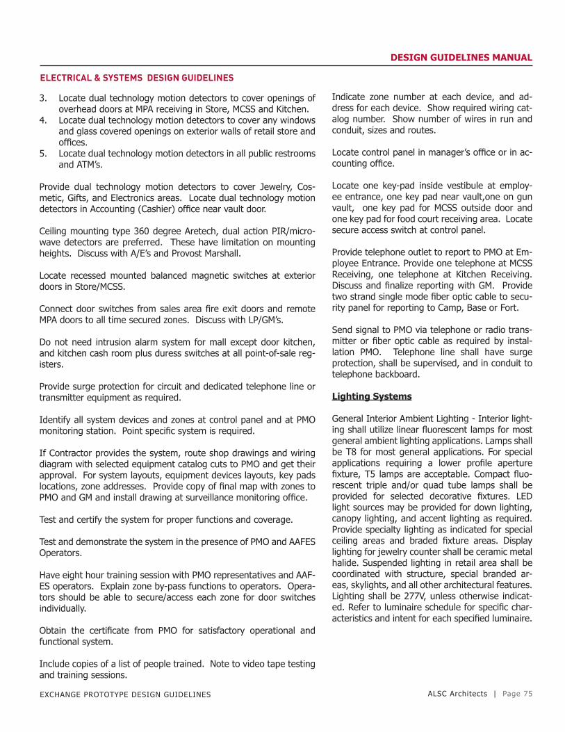
EXCHANGE PROTOTYPE DESIGN GUIDELINES ALSC Architects | Page 75
DESIGN GUIDELINES MANUAL
ELECTRICAL & SYSTEMS DESIGN GUIDELINES
3. Locate dual technology motion detectors to cover openings of overhead doors at MPA receiving in Store, MCSS and Kitchen.
4. Locate dual technology motion detectors to cover any windows and glass covered openings on exterior walls of retail store and offices.
5. Locate dual technology motion detectors in all public restrooms and ATM’s.
Provide dual technology motion detectors to cover Jewelry, Cos-metic, Gifts, and Electronics areas. Locate dual technology motion detectors in Accounting (Cashier) office near vault door.
Ceiling mounting type 360 degree Aretech, dual action PIR/micro-wave detectors are preferred. These have limitation on mounting heights. Discuss with A/E’s and Provost Marshall.
Locate recessed mounted balanced magnetic switches at exterior doors in Store/MCSS.
Connect door switches from sales area fire exit doors and remote MPA doors to all time secured zones. Discuss with LP/GM’s.
Do not need intrusion alarm system for mall except door kitchen, and kitchen cash room plus duress switches at all point-of-sale reg-isters.
Provide surge protection for circuit and dedicated telephone line or transmitter equipment as required.
Identify all system devices and zones at control panel and at PMO monitoring station. Point specific system is required.
If Contractor provides the system, route shop drawings and wiring diagram with selected equipment catalog cuts to PMO and get their approval. For system layouts, equipment devices layouts, key pads locations, zone addresses. Provide copy of final map with zones to PMO and GM and install drawing at surveillance monitoring office.
Test and certify the system for proper functions and coverage.
Test and demonstrate the system in the presence of PMO and AAFES Operators.
Have eight hour training session with PMO representatives and AAF-ES operators. Explain zone by-pass functions to operators. Opera-tors should be able to secure/access each zone for door switches individually.
Obtain the certificate from PMO for satisfactory operational and functional system.
Include copies of a list of people trained. Note to video tape testing and training sessions.
Indicate zone number at each device, and ad-dress for each device. Show required wiring cat-alog number. Show number of wires in run and conduit, sizes and routes.
Locate control panel in manager’s office or in ac-counting office.
Locate one key-pad inside vestibule at employ-ee entrance, one key pad near vault,one on gun vault, one key pad for MCSS outside door and one key pad for food court receiving area. Locate secure access switch at control panel.
Provide telephone outlet to report to PMO at Em-ployee Entrance. Provide one telephone at MCSS Receiving, one telephone at Kitchen Receiving. Discuss and finalize reporting with GM. Provide two strand single mode fiber optic cable to secu-rity panel for reporting to Camp, Base or Fort.
Send signal to PMO via telephone or radio trans-mitter or fiber optic cable as required by instal-lation PMO. Telephone line shall have surge protection, shall be supervised, and in conduit to telephone backboard.
Lighting Systems
General Interior Ambient Lighting - Interior light-ing shall utilize linear fluorescent lamps for most general ambient lighting applications. Lamps shall be T8 for most general applications. For special applications requiring a lower profile aperture fixture, T5 lamps are acceptable. Compact fluo-rescent triple and/or quad tube lamps shall be provided for selected decorative fixtures. LED light sources may be provided for down lighting, canopy lighting, and accent lighting as required. Provide specialty lighting as indicated for special ceiling areas and braded fixture areas. Display lighting for jewelry counter shall be ceramic metal halide. Suspended lighting in retail area shall be coordinated with structure, special branded ar-eas, skylights, and all other architectural features. Lighting shall be 277V, unless otherwise indicat-ed. Refer to luminaire schedule for specific char-acteristics and intent for each specified luminaire.
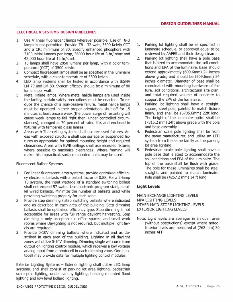
EXCHANGE PROTOTYPE DESIGN GUIDELINES ALSC Architects | Page 76
DESIGN GUIDELINES MANUAL
ELECTRICAL & SYSTEMS DESIGN GUIDELINES
1. Use 4’ linear fluorescent lamps wherever possible. Use of T8-U lamps is not permitted. Provide T8 - 32 watt, 3500 Kelvin CCT and a CRI minimum of 80. Specify enhanced phosphors with 3100 initial lumens per lamp, 36000 hour life at 3 hr/ start and 42,000 hour life at 12 hr/start.
2. T5 lamps shall have 2850 lumens per lamp, with a color tem-perature (CCT) of 3500 kelvin.
3. Compact fluorescent lamps shall be as specified in the luminaire schedule, with a color temperature of 3500 kelvin.
4. LED lamp systems shall be tested in accordance with IESNA LM-79 and LM-80. System efficacy should be a minimum of 80 lumens per watt.
5. Metal Halide lamps. Where metal halide lamps are used inside the facility, certain safety precautions must be enacted. To re-duce the chance of a non-passive failure, metal halide lamps must be operated in their proper orientation, shut off for 15 minutes at least once a week (the power surge of restarting will cause weak lamps to fail right then, under controlled circum-stances), changed at 70 percent of rated life, and enclosed in fixtures with tempered glass lenses.
6. Areas with Tbar ceiling systems shall use recessed fixtures. Ar-eas with exposed structure shall use surface or suspended fix-tures as appropriate for optimal mounting height and required clearances. Areas with GWB ceilings shall use recessed fixtures where possible to maximize clearances. Where framing will make this impractical, surface mounted units may be used.
Fluorescent Ballast Systems
1. For linear fluorescent lamp systems, provide optimized efficien-cy electronic ballasts with a ballast factor of 0.88. For a 2-lamp T8 system, the input wattage of a standard switching ballast shall not exceed 57 watts. Use electronic program start, paral-lel wired ballasts. Minimize the number of ballasts used while providing switching properly for each zone.
2. Provide step dimming / step switching ballasts where indicated and as described in each area of the building. Step dimming ballasts shall be optimized efficiency type. Step dimming is not acceptable for areas with full range daylight harvesting. Step dimming is only acceptable in office spaces, and small work rooms where Daylighting is not required, but multiple light lev-els are required.
3. Provide 0-10V dimming ballasts where indicated and as de-scribed in each area of the building. Lighting in all daylight zones will utilize 0-10V dimming. Dimming single will come from output on lighting control module, which receives a low voltage analog input from a photocell in each dimming zone. One pho-tocell may provide data for multiple lighting control modules.
Exterior Lighting Systems – Exterior lighting shall utilize LED lamp systems, and shall consist of parking lot area lighting, pedestrian scale pole lighting, under canopy lighting, building mounted flood lighting and low level bollard lighting.
1. Parking lot lighting shall be as specified in luminaire schedule, or approved equal to be reviewed by AAFES and their design team.
2. Parking lot lighting shall have a pole base that is sized to accommodate the soil condi-tions and EPA of the luminaire. Base should extend approximately (609.6mm) 24 inches above grade, and should be (609.6mm) 24 inches diameter. Diameter of base shall be coordinated with mounting hardware of fix-ture, soil conditions, architectural site plan, and total required volume of concrete to support the EPA of the luminaire.
3. Parking lot lighting shall have a straight, square, steel pole, painted to match fixture finish, and shall be (6705.6mm) 22ft long. The height of the luminaire optics shall be (7315.2 mm) 24ft above grade with the pole and base assembly.
4. Pedestrian scale pole lighting shall be from the same manufacturer, and utilize an LED system from the same family as the parking lot area lighting.
5. Pedestrian scale pole lighting shall have a pole base that is sized to accommodate the soil conditions and EPA of the luminaire. The top of the base shall be flush with grade. The pole for these luminaires shall be steel, straight, and painted to match luminaire. Pole shall be (4267.2 mm) 14 ft long.
Light Levels
MAIN EXCHANGE LIGHTING LEVELSMPA LIGHTING LEVELSOTHER MAIN STORE LIGHTING LEVELSEXTERIOR LIGHTING LEVELS
Note: Light levels are averages in an open area (without obstructions) except where noted. Interior levels are measured at (762 mm) 30 inches AFF.
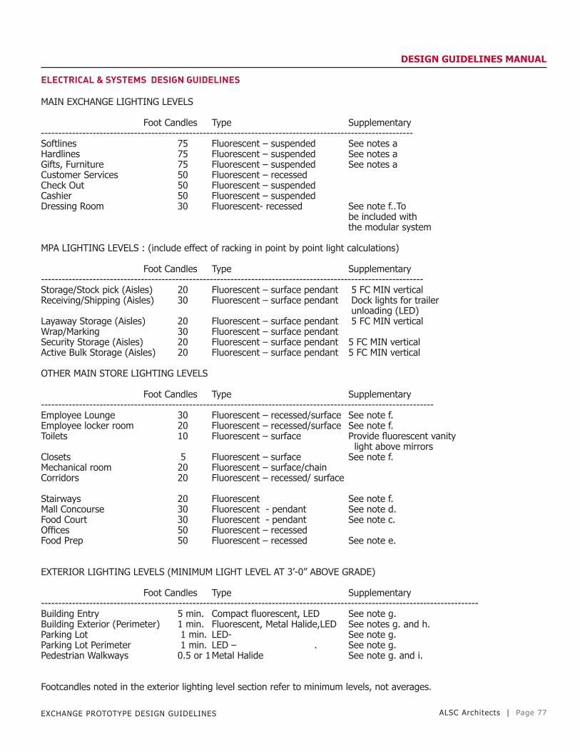
EXCHANGE PROTOTYPE DESIGN GUIDELINES ALSC Architects | Page 77
DESIGN GUIDELINES MANUAL
ELECTRICAL & SYSTEMS DESIGN GUIDELINES
MAIN EXCHANGE LIGHTING LEVELS
Foot Candles Type Supplementary------------------------------------------------------------------------------------------------------------Softlines 75 Fluorescent – suspended See notes a Hardlines 75 Fluorescent – suspended See notes aGifts, Furniture 75 Fluorescent – suspended See notes aCustomer Services 50 Fluorescent – recessedCheck Out 50 Fluorescent – suspended Cashier 50 Fluorescent – suspended Dressing Room 30 Fluorescent- recessed See note f..To be included with the modular system MPA LIGHTING LEVELS : (include effect of racking in point by point light calculations)
Foot Candles Type Supplementary---------------------------------------------------------------------------------------------------------------Storage/Stock pick (Aisles) 20 Fluorescent – surface pendant 5 FC MIN verticalReceiving/Shipping (Aisles) 30 Fluorescent – surface pendant Dock lights for trailer unloading (LED)Layaway Storage (Aisles) 20 Fluorescent – surface pendant 5 FC MIN verticalWrap/Marking 30 Fluorescent – surface pendant Security Storage (Aisles) 20 Fluorescent – surface pendant 5 FC MIN verticalActive Bulk Storage (Aisles) 20 Fluorescent – surface pendant 5 FC MIN vertical
OTHER MAIN STORE LIGHTING LEVELS
Foot Candles Type Supplementary------------------------------------------------------------------------------------------------------------------Employee Lounge 30 Fluorescent – recessed/surface See note f.Employee locker room 20 Fluorescent – recessed/surface See note f.Toilets 10 Fluorescent – surface Provide fluorescent vanity light above mirrorsClosets 5 Fluorescent – surface See note f.Mechanical room 20 Fluorescent – surface/chain Corridors 20 Fluorescent – recessed/ surface
Stairways 20 Fluorescent See note f.Mall Concourse 30 Fluorescent - pendant See note d.Food Court 30 Fluorescent - pendant See note c.Offices 50 Fluorescent – recessed Food Prep 50 Fluorescent – recessed See note e.
EXTERIOR LIGHTING LEVELS (MINIMUM LIGHT LEVEL AT 3’-0” ABOVE GRADE)
Foot Candles Type Supplementary-------------------------------------------------------------------------------------------------------------------------------Building Entry 5 min. Compact fluorescent, LED See note g.Building Exterior (Perimeter) 1 min. Fluorescent, Metal Halide,LED See notes g. and h.Parking Lot 1 min. LED- See note g.Parking Lot Perimeter 1 min. LED – . See note g.Pedestrian Walkways 0.5 or 1 Metal Halide See note g. and i.
Footcandles noted in the exterior lighting level section refer to minimum levels, not averages.

EXCHANGE PROTOTYPE DESIGN GUIDELINES ALSC Architects | Page 78
DESIGN GUIDELINES MANUAL
ELECTRICAL & SYSTEMS DESIGN GUIDELINESFOOTNOTES:
a. Suspended fluorescent lighting at (4.267 meters) 14ft above finished floor, in continuous rows (3.657 M) 12 ft on center. Fixtures shall use high reflectance white reflectors and cross baffles for lamp shielding. Housing shall have apertures for 10% uplight minimum. Main sales area shall be provided with skylights. The electrical lighting shall have daylight harvesting strategies to lower the electrical lighting component to accom-modate the daylight levels available. Fixtures shall have 0-10v dimming ballasts which are controlled with photocells via net-workable lighting control modules. Closed loop strategies shall be used. Photocells and modules to be factory commissioned for light level requirements. Photocell placements are to be established based on factory provided shop drawings.
b. Façade lighting shall be provided at the building entry and building perimeter. Allowance is 3.5 Watts per linear foot along the perimeter. Lighting should be building mounted and full cutoff. Area adjacent to the building shall be provided with 1 footcandle minimum to a distance of (6.096M) 20’ from the building perimeter.
c. Provide uniform wall washing on the “Cityscapes” mural to 30 vertical FC minimum.
d. Provide wall washing on “Hall of Honor” wall to 30 vertical FC minium.
e. Provide gasketing between door frame and housing.
f. Provide occupancy sensors
g. This is a minimum footcandle requirement, not an average. Ave/min ratio should be no greater than 5:1. Minimize average while meeting minimum requirement.
h. Provide a minimum of 5 footcandles for the threshold area of 5’ to either side and 10’ in front of the entry door. Emergency illumination shall be provided in that same area to 1 FC mini-mum.
i. Walkways adjacent to parking areas and roadways shall be provided with 1 footcandle minimum. Walkways not adjacent to parking or roadways shall be provided with a 0.5 footcandle minimum.

EXCHANGE PROTOTYPE DESIGN GUIDELINES ALSC Architects | Page 79
DESIGN GUIDELINES MANUAL
ELECTRICAL & SYSTEMS DESIGN GUIDELINES
MILITARY CLOTHING SALES STORE (MCSS) LIGHTING LEVELS
This standard gives lighting levels for all areas of the Military Clothing Sales Store (MCSS) whether freestanding or part of mall and guidance on other lighting needs. Refer to Main Exchange section for exterior lighting standards.
MCSS LIGHTING LEVELSMCSS MPA LIGHTING LEVELSOTHER MCSS LIGHTING LEVELS
MCSS LIGHTING LEVELS Foot Candles Type Supplementary--------------------------------------------------------------------------------------------------------------------Retail Sales Area 75 Fluorescent – recessed Customer Services 50 Fluorescent – recessed Check –Out 50 Fluorescent – recessed Cashier 50 Fluorescent – recessed Dressing Room 30 Compact Fluorescent See note f. To be included with the modular system
MCSS MPA LIGHTING LEVELS : (include effect of racking in point by point calculations) Foot Candles Type Supplementary---------------------------------------------------------------------------------------------------------------------Storage/Stock pick (Aisles) 20 Fluorescent – surface/pendant 5 FC MIN vertical StripsReceiving/Shipping (Aisles) 30 Fluorescent – surface/pendant LED Dock lights for trailer unloading Layaway/Storage (Aisles) 20 Fluorescent – surface/pendant 5 FC MIN verticalWrap/Marking 30 Fluorescent – surface/pendant Security Storage 20 Fluorescent – surface/pendant 5 FC MIN verticalActive Bulk Storage 20 Fluorescent – surface/pendant 5 FC MIN vertical
OTHER MCSS LIGHTING LEVELS Foot Candles Type Supplementary---------------------------------------------------------------------------------------------------------------------Employee Lounge 30 Fluorescent – recessed/surfaceLocker Room 20 Fluorescent – recessed/surface Toilets 10 Fluorescent – surfaceClosets 5 Fluorescent – surfaceMechanical Room 20 Fluorescent – surface/pendantCorridors 20 Fluorescent – recessedStairways 20 Fluorescent – recessed / surface Offices 50 Fluorescent – recessed
PORTRAIT STUDIO LIGHTING LEVELS Foot Candles Type Supplementary---------------------------------------------------------------------------------------------------------------------Customer Waiting 30 Fluorescent – recessedStudio 30 Fluorescent – recessed Concessionaire provides photo lightingVanity 30 Fluorescent – recessed Incandescent at mirror
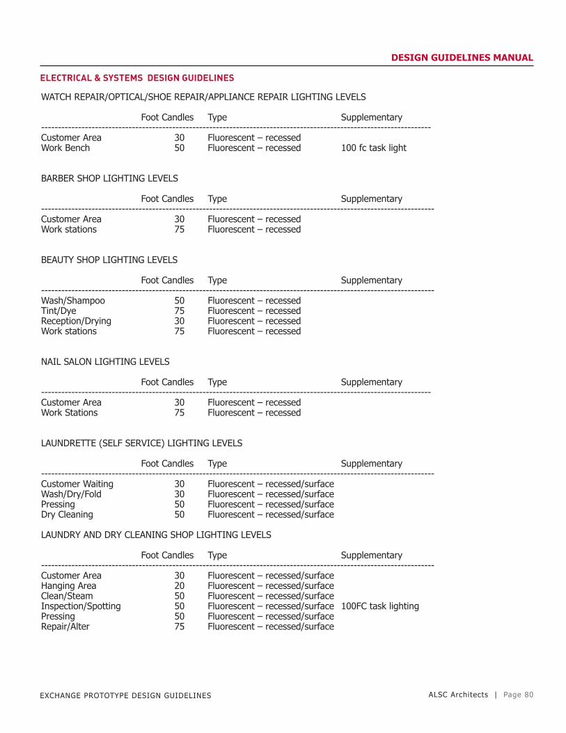
EXCHANGE PROTOTYPE DESIGN GUIDELINES ALSC Architects | Page 80
DESIGN GUIDELINES MANUAL
ELECTRICAL & SYSTEMS DESIGN GUIDELINES
WATCH REPAIR/OPTICAL/SHOE REPAIR/APPLIANCE REPAIR LIGHTING LEVELS
Foot Candles Type Supplementary-------------------------------------------------------------------------------------------------------------------- Customer Area 30 Fluorescent – recessed Work Bench 50 Fluorescent – recessed 100 fc task light
BARBER SHOP LIGHTING LEVELS
Foot Candles Type Supplementary---------------------------------------------------------------------------------------------------------------------Customer Area 30 Fluorescent – recessed Work stations 75 Fluorescent – recessed
BEAUTY SHOP LIGHTING LEVELS
Foot Candles Type Supplementary---------------------------------------------------------------------------------------------------------------------Wash/Shampoo 50 Fluorescent – recessed Tint/Dye 75 Fluorescent – recessedReception/Drying 30 Fluorescent – recessedWork stations 75 Fluorescent – recessed
NAIL SALON LIGHTING LEVELS
Foot Candles Type Supplementary--------------------------------------------------------------------------------------------------------------------Customer Area 30 Fluorescent – recessedWork Stations 75 Fluorescent – recessed
LAUNDRETTE (SELF SERVICE) LIGHTING LEVELS
Foot Candles Type Supplementary---------------------------------------------------------------------------------------------------------------------Customer Waiting 30 Fluorescent – recessed/surfaceWash/Dry/Fold 30 Fluorescent – recessed/surfacePressing 50 Fluorescent – recessed/surfaceDry Cleaning 50 Fluorescent – recessed/surface
LAUNDRY AND DRY CLEANING SHOP LIGHTING LEVELS
Foot Candles Type Supplementary---------------------------------------------------------------------------------------------------------------------Customer Area 30 Fluorescent – recessed/surfaceHanging Area 20 Fluorescent – recessed/surface Clean/Steam 50 Fluorescent – recessed/surfaceInspection/Spotting 50 Fluorescent – recessed/surface 100FC task lightingPressing 50 Fluorescent – recessed/surface Repair/Alter 75 Fluorescent – recessed/surface
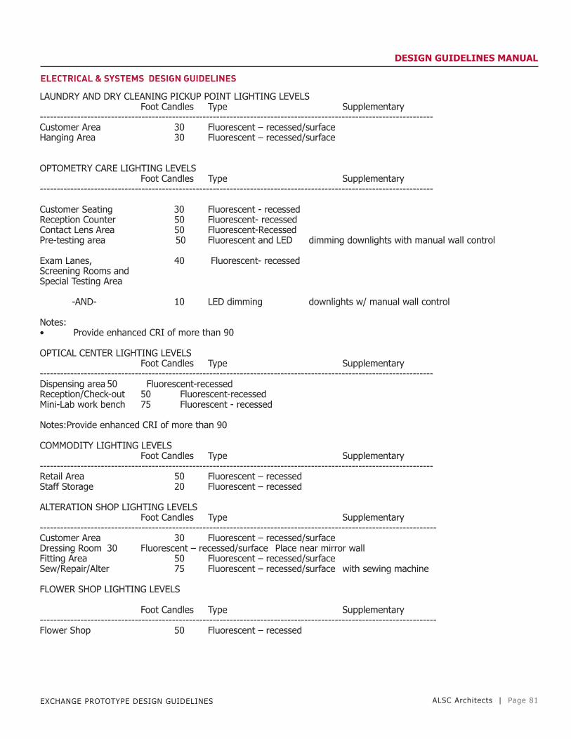
EXCHANGE PROTOTYPE DESIGN GUIDELINES ALSC Architects | Page 81
DESIGN GUIDELINES MANUAL
ELECTRICAL & SYSTEMS DESIGN GUIDELINES
LAUNDRY AND DRY CLEANING PICKUP POINT LIGHTING LEVELS Foot Candles Type Supplementary--------------------------------------------------------------------------------------------------------------------Customer Area 30 Fluorescent – recessed/surfaceHanging Area 30 Fluorescent – recessed/surface
OPTOMETRY CARE LIGHTING LEVELS Foot Candles Type Supplementary--------------------------------------------------------------------------------------------------------------------
Customer Seating 30 Fluorescent - recessedReception Counter 50 Fluorescent- recessed Contact Lens Area 50 Fluorescent-Recessed Pre-testing area 50 Fluorescent and LED dimming downlights with manual wall control Exam Lanes, 40 Fluorescent- recessed Screening Rooms and Special Testing Area
-AND- 10 LED dimming downlights w/ manual wall control
Notes:• Provide enhanced CRI of more than 90
OPTICAL CENTER LIGHTING LEVELS Foot Candles Type Supplementary--------------------------------------------------------------------------------------------------------------------Dispensing area 50 Fluorescent-recessed Reception/Check-out 50 Fluorescent-recessed Mini-Lab work bench 75 Fluorescent - recessed
Notes:Provide enhanced CRI of more than 90
COMMODITY LIGHTING LEVELS Foot Candles Type Supplementary--------------------------------------------------------------------------------------------------------------------Retail Area 50 Fluorescent – recessedStaff Storage 20 Fluorescent – recessed
ALTERATION SHOP LIGHTING LEVELS Foot Candles Type Supplementary---------------------------------------------------------------------------------------------------------------------Customer Area 30 Fluorescent – recessed/surfaceDressing Room 30 Fluorescent – recessed/surface Place near mirror wall Fitting Area 50 Fluorescent – recessed/surface Sew/Repair/Alter 75 Fluorescent – recessed/surface with sewing machine
FLOWER SHOP LIGHTING LEVELS
Foot Candles Type Supplementary---------------------------------------------------------------------------------------------------------------------Flower Shop 50 Fluorescent – recessed

EXCHANGE PROTOTYPE DESIGN GUIDELINES ALSC Architects | Page 82
DESIGN GUIDELINES MANUAL
ELECTRICAL & SYSTEMS DESIGN GUIDELINES
Lighting Controls - Centralized Panel Network
General – Provide a centralized lighting control panel network consisting of lighting control panels, lighting control modules, and various input control devices. One panel shall be designated as the master panel, and shall have an integral programmable processor with a built in astronomical time clock. Each relay shall be individu-ally programmable and respond to programming of the time-clock, as well as digital, analog, and other low voltage inputs. These inputs will include occupancy sensors, photocells, digital switches, low voltage momentary contact switches, and inputs from other systems. Inputs from other systems may communicate via dry contact closures. Head end panel shall also include an Ethernet interface to accommodate connection to other building systems, such as an energy management system (EMS) or building automa-tion system (BAS).This interface shall communicate over a pro-tocol such as BacNet or LonWorks. Coordinate requirements with mechanical system provider.
In addition to the panels, there will also be lighting control mod-ules that contain (4) relays for on/off control, and (4) 0-10V dim-ming outputs. These modules will accept inputs from photocells and occupancy sensors, as well as digital switches. These modules are also network devices, and will be connected to the centralized lighting control panel network. These modules will be used in all applications that full range dimming and daylight harvesting are required.
1. In rooms large enough to warrant full range day lighting (larg-er than 10 square meters with horizontal or vertical glazing), a primary and secondary daylight zone shall each be estab-lished, based on their proximity to the exterior glazing. Closed loop daylight harvesting shall be utilized, and each zone shall be calibrated to adjust the associated level of artificial light in that zone, to maintain an even illumination throughout the entire space. (i.e. the light in the zone right next to the glazing (the primary zone), will reduce output more than the second-ary zone, which will reduce output more than the non-daylight zones.
2. For vertical glazing, the primary daylight zone shall extend (609.6mm) 2 ft adjacent to either side of the glazing, and ex-tend out into the room a length equal to the height of the top of the glazing. The secondary daylight zone shall extend two times the height of the glazing. (i.e. vertical glazing of a height of (400mm) 15.7 inches would result in a primary daylight zone that extends 400mm from the glazing into the space, and a secondary daylight zone that extends from (400mm to 800mm), 15.7 inches to 31.5 inches.
Each digital and low voltage switch shall be given a unique identifi-cation for programming purposes.
All common areas, including corridors, shops, the mall concourse, and other circulation areas, as well as all exterior lighting, will be controlled from the centralized panel network. Each relay will be controlled by a specific time schedule as determined by the build-ing administration, and also from a local digital switch. Regional sub-master and master switches shall also be provided. A master
switch should be provided for each building area, including the Retail area, the mall concourse, the administration area, MPA, MCSS, etc., shall all have master switches located in the administra-tion area in a secure location that is coordinated with the owner. System shall be capable of as-signing priority to devices and control functions based on the time of day. For example, local digital switches shall be disabled during certain business hours when the administration or the tenant does not want the lights to be turned off.
Not all lighting control devices are shown. Supply lighting control panels and modules as needed for complete control of facility.
Lighting Controls - Local Occupancy Based Control
In addition to the centralized panel network that provides complete sweep off capabilities on a time schedule, provide local occupancy based control for rooms as indicated on the drawings.
All offices and administrative areas shall have local occupancy based control. Rooms smaller than approximately 12 square meters shall utilize wall-type occupancy sensor switches. Larger rooms shall use ceiling mounted type sensors and standard 1P-20A wall switches. All devices shall be downstream of building lighting control network.
1. All occupancy sensors shall be dual technol-ogy (ultra-sonic & passive infrared).
a. Occupancy sensors shall be calibrated to turn lights off within 15 minutes of vacancy. Sensors shall be calibrated to detect motion in all areas of the room. Manual on, automatic off modes shall be available to the owner at their discretion. (i.e. Lights will only turn off automatically, and not turn on. An energy saving strategy).
2. Coordinate exact location and type of occu-pancy sensors with manufacturer’s recom-mendations. Use coverage patterns that are ideal for each room’s geometry.

EXCHANGE PROTOTYPE DESIGN GUIDELINES ALSC Architects | Page 83
DESIGN GUIDELINES MANUAL
ELECTRICAL & SYSTEMS DESIGN GUIDELINES
3. Offices and work rooms shall utilize bi-level step dimming con-trol. Refer to luminaire schedule to determine luminaires that require bi-level control.
a. All wall type occupancy sensor switches in rooms with bi-level control shall have two buttons, one for each stepped level of light (0%, 50%, 100%).
4. All occupancy sensors shall be downstream of a relay in cen-tralized lighting control panel network.
Emergency Lighting
Emergency lighting will be the self-contained battery typ.
Design emergency lighting to provide a minimum of 1 Footcandle (10 lux) on the entire path of egress. Coordinate design of emer-gency lighting with architectural code plan.
Provide exit signs at all required exits, and as guides along the path of egress. Coordinate location of all exit signs with architec-tural code plan. Not all exit signs are shown on the drawing. Engi-neer finishing construction documents is responsible for complet-ing emergency lighting and egress lightings in accordance with the local authority having jurisdiction.
EXCHANGE PROTOTYPE DESIGN GUIDELINES ALSC Architects | Page 84
DESIGN GUIDELINES MANUAL
PROTOTYPE LEED
CRITERIAGUIDELINES
EXCHANGE PROTOTYPE DESIGN GUIDELINES ALSC Architects | Page 85
DESIGN GUIDELINES MANUAL
PROTOTYPE LEED CRITERIA GUIDELINES
WE PRE-REQUISITE 1 - WATER USE REDUCTIONUse 20% less water than the water use baseline calculated for the building, not including irrigation.
WE CREDIT 2 - INNOVATIVE WASTEWATER TECHNOLOGIESReduce potable water use for sewage conveyance by 50% or treat 50% of wastewater on-site to tertiary standards.
WE CREDIT 3 - WATER USE REDUCTIONUse less water than the water use baseline calculated for the build-ing (not including irrigation) by 30%.
EA PREREQUISITE 1 - FUNDAMENTAL COMMISSIONINGVerify that energy-related systems are installed and calibrated to perform as intended.
EA PREREQUISITE 2 - MINIMUM ENERGY PERFORMANCEEstablish a minimum level of energy performance for the building and systems through simulation or prescriptive compliance path.
EA PREREQUISITE 3 - FUNDAMENTAL REFRIGERANT MAN-AGEMENTCompletely eliminate use of CFC-based refrigerants.
EA CREDIT 1 - OPTIMIZE ENERGY PERFORMANCEImprove energy performance by 34% for new buildings and by 30% for existing buildings.
EA CREDIT 2 - ON-SITE RENEWABLE ENERGYUse renewable on-site energy systems to offset 5% of the energy usage cost for the building.
EA CREDIT 3 - ENHANCED COMMISSIONINGBegin commissioning early in the design process and execute addi-tional activities after systems performance verification is complete, as described in LEED guidelines.
EA CREDIT 4 - ENHANCED REFRIGERANT MANAGEMENTEither do not use refrigerants, or select equipment that minimize the emission of compounds that contribute to climate change.
EA CREDIT 5 - MEASUREMENT AND VERIFICATIONProvide for on-going accountability of building energy consumption over time, for 1 year of post-construction occupancy
MR PREREQUISITE 1 - STORAGE AND COLLECTION OF RE-CYCLABLESConduct a waste stream study, and provide a dedicated area for storage and collection of recyclables.
MR CREDIT 2 - CONSTRUCTION WASTE MANAGEMENTDevelop a plan to divert 50% of construction and demolition debris from landfills.
MR CREDIT 4 - RECYCLED CONTENTUse materials with recycled content that consti-tutes 10% of the total value of the materials in the project.
MR CREDIT 5 - REGIONAL MATERIALSUse materials that have been manufactured, har-vested, extracted, or recovered within 500 miles of the project site. Regional materials should be a minimum of 20% of the total materials value.
EA CREDIT 6 - RAPIDLY RENEWABLE MA-TERIALSUse rapidly renewable materials for 2.5% of the total value of all building materials, based on cost
EA CREDIT 7 - CERTIFIED WOODUse a minimum of 50% of wood based materi-als and products that are certified. Millwork and casework must be included. Furniture and fix-tures may be included.
IEQ PREREQUISITE 1 - MINIMUM INDOOR AIR QUALITY PERFORMANCEMeet the requirements of ASHRAE 62.1-2007, sections 4-7.
IEQ PREREQUISITE 2 - ETS CONTROLProhibit smoking in the building.
IEQ CREDIT 3.1 - IAQ MANAGEMENT PLAN - CONSTRUCTIONDevelop an IAQ plan for the construction and pre-occupancy phases of the project.
IEQ CREDIT 3.2 - IAQ MANAGEMENT PLAN - PRE-OCCUPANCYFlush out the building after construction and be-fore occupancy at 14,000 CF of outdoor air per sf. Or flush out the building during occupancy with 3,500 CF or air per SF at .3 CFM.
IEQ CREDIT 4.1/2/3/4 - LOW EMITTING MATERIALSUse products and materials that comply with leed requirements, including adhesives and sealants, paints, coatings, flooring, furniture and furnish-ings, ceiling and wall systems.
IEQ CREDIT 5 - INDOOR CHEMICAL AND POLLUTANT SOURCE CONTROLDesign to minimize and control the entry of pol-lutants into buildings and later cross-contamina-tion of regularly occupied areas.
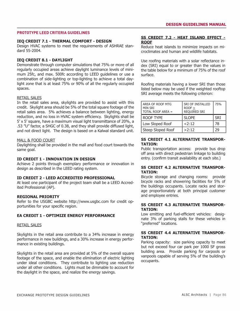
EXCHANGE PROTOTYPE DESIGN GUIDELINES ALSC Architects | Page 86
DESIGN GUIDELINES MANUAL
PROTOTYPE LEED CRITERIA GUIDELINES
IEQ CREDIT 7.1 - THERMAL COMFORT - DESIGNDesign HVAC systems to meet the requirements of ASHRAE stan-dard 55-2004.
IEQ CREDIT 8.1 - DAYLIGHTDemonstrate through computer simulations that 75% or more of all regularly occupied areas achieve daylight luminance levels of mini-mum 25fc, and max. 500fc according to LEED guidelines or use a combination of side-lighting or top-lighting to achieve a total day-light zone that is at least 75% or 90% of all the regularly occupied spaces.
RETAIL SALESIn the retail sales area, skylights are provided to assist with this credit. Skylight area should be 5% of the total square footage of the retail sales area. 5% achieves a balance between lighting, energy reduction, and no loss in HVAC system efficiency. Skylights shall be 5’ x 5’ square, have a maximum visual light transmittance of 20%, a .53 ”U” factor, a SHGC of 0.38, and they shall provide diffused light, and not direct light. The design is based on a Kalwal standard unit.
MALL & FOOD COURTDaylighting shall be provided in the mall and food court towards the same goal.
ID CREDIT 1 - INNOVATION IN DESIGNAchieve 2 points through exemplary performance or innovation in design as described in the LEED rating system.
ID CREDIT 2 - LEED ACCREDITED PROFESSIONALAt least one participant of the project team shall be a LEED Accred-ited Professional (AP).
REGIONAL PRIORITYRefer to the USGBC website http://www.usgbc.com for credit op-portunities for your specific region.
EA CREDIT 1 - OPTIMIZE ENERGY PERFORMANCE
RETAIL SALES
Skylights in the retail area contribute to a 34% increase in energy performance in new buildings, and a 30% increase in energy perfor-mance in existing buildings.
Skylights in the retail area are provided at 5% of the overall square footage of the space, and enable the elimination of electric lighting under ideal conditions. They contribute to lighting use reduction under all other conditions. Lights must be dimmable to account for the daylight in the space, and realize the energy savings.
SS CREDIT 7.2 - HEAT ISLAND EFFECT - ROOFReduce heat islands to minimize impacts on mi-croclimates and human and wildlife habitats.
Use roofing materials with a solar reflectance in-dex (SRI) equal to or greater than the values in the table below for a minimum of 75% of the roof surface.
Roofing materials having a lower SRI than those listed below may be used if the weighted rooftop SRI average meets the following criterion: AREA OF ROOF MTG MIN SRI TOTAL ROOF AREA =
SRI OF INSTALLED ROOF > REQUIRED SRI
75%
ROOF TYPE SLOPE SRI
Low Sloped Roof <2:12 78
Steep Sloped Roof >2:12 29
SS CREDIT 4.1 ALTERNATIVE TRANSPOR-TATION:Public transportation access: provide bus drop off area with direct pedestrian linkage to building entry. (confirm transit availability at each site.)
SS CREDIT 4.2 ALTERNATIVE TRANSPOR-TATION:Bicycle storage and changing rooms: provide bicycle racks and showering facilities for 5% of the buildings occupants. Locate racks and stor-age proportionately at both principal customer and employee entries.
SS CREDIT 4.3 ALTERNATIVE TRANSPOR-TATION:Low emitting and fuel-efficient vehicles: desig-nate 3% of parking stalls for these vehicles in “preferred” locations.
SS CREDIT 4.4 ALTERNATIVE TRANSPOR-TATION:Parking capacity: size parking capacity to meet but not exceed four car park per 1000 SF gross building area. Provide parking for carpools or vanpools capable of serving 5% of the building’s occupants.

EXCHANGE PROTOTYPE DESIGN GUIDELINES ALSC Architects | Page 87
DESIGN GUIDELINES MANUAL
PROTOTYPE LEED CRITERIA GUIDELINES
SS CREDIT 5.1 REDUCED SITE DISTURBANCE:Protect or restore open space: where opportunities exist, develop a minimum of 50% of the site area (excluding bldg. Footprint) replac-ing impervious surfaces with native or adapted vegetation.
SS CREDIT 6.1 STORMWATER MANAGEMENT:Quantity control: design the site with swales to promote infiltration resulting in a 25% reduction of storm water runoff.
SS CREDIT 6.2 STORMWATER MANAGEMENT:Treatment: design natural stormwater treatment system utilizing vegetated filterstrips or bioswales.
SS CREDIT 8.0 LIGHT POLLUTION REDUCTION:Minimize site lighting to meet exchange design standards. Provide shielding such that no light from luminaries crosses property bound-aries.
WE CREDIT 1.1. WATER EFFICIENCY:Water efficient landscaping: reduce landscape irrigation by 50%. Use high-efficiency irrigation systems.
MRP1 MR PREREQ 1 MATERIALS AND RESOURCES:Storage and collection of recyclables: designate an area for recy-clable collection appropriately sized for collection of glass, plastic, newspaper, cardboard and organic wastes. Site screen pallet and baled paper storage.
MR CREDIT 4.2 RECYCLED CONTENT:10% (post-consumer + 1/2 post-industrial): use recycled products of demolition such as asphalt paving and concrete (free or reinforc-ing).
LEED NOTES LEGEND
SS- Sustainable SitesWE- Water EfficiencyMR- Materials and ResourcesID- Innovation and Design process

EXCHANGE PROTOTYPE DESIGN GUIDELINES ALSC Architects | Page 88
DESIGN GUIDELINES MANUAL
ELECTRICAL & SYSTEMS DESIGN GUIDELINES


![[SIP 2015] Design Proposal: Design and animated prototype](https://static.fdocuments.net/doc/165x107/587c51351a28abc62c8b5de7/sip-2015-design-proposal-design-and-animated-prototype.jpg)


