December 1997 Alerts - faa.gov · December 1997 FAA AC 43-16 1 ... communication channel through...
27
General Aviation Airworthiness Alerts AC No. 43-16 ALERT NO. 233 DECEMBER 1997 Improve Reliability- Interchange Service Experience ALERTS
Transcript of December 1997 Alerts - faa.gov · December 1997 FAA AC 43-16 1 ... communication channel through...

General AviationAirworthinessAlerts
AC No. 43-16
ALERT NO. 233DECEMBER 1997
Improve Reliability-Interchange ServiceExperience
A LER TS
Contents of this publication are informational only. Due to the need for extensive distribution of this publication,only one copy is provided to an addressee; however, this publication may be duplicated.
CONTENTS
AIRCRAFT
AMERICAN CHAMPION ..................................................................................................... 1BEECH................................................................................................................................... 2CESSNA ................................................................................................................................. 5MOONEY ............................................................................................................................... 8PIPER .................................................................................................................................... 9UNIVAIR ............................................................................................................................. 12
HELICOPTERS
BELL .................................................................................................................................... 13ENSTROM ........................................................................................................................... 14SCHWEIZER ....................................................................................................................... 14
AMATEUR, EXPERIMENTAL, AND SPORT AIRCRAFT
REVOLUTION HELICOPTER .......................................................................................... 14
PROPELLERS AND POWERPLANTS
ALLISON ............................................................................................................................. 15HARTZELL .......................................................................................................................... 15
ACCESSORIES
UPDATE ON DEFECTIVE INSTRUMENT AIR FILTERS ............................................ 15
AIR NOTES
AIRWORTHINESS DIRECTIVES (AD’S) ISSUED IN OCTOBER 1997 ........................ 16HAPPY HOLIDAYS ............................................................................................................. 17PROFESSIONAL RIDER ................................................................................................... 18ALERTS ONLINE ............................................................................................................... 19ELECTRONIC AVAILABILITY OF INFORMATION ..................................................... 20SUSPECTED UNAPPROVED PARTS SEMINAR ........................................................... 20FAA FORM 8010-4, MALFUNCTION OR DEFECT REPORT ........................................ 21SUBSCRIPTION REQUEST FORM .................................................................................. 21

December 1997 FAA AC 43-16
1
FLIGHT STANDARDS SERVICEMike Monroney Aeronautical Center
The General Aviation Airworthiness Alerts provide a commoncommunication channel through which the aviation commu-nity can economically interchange service experience andthereby cooperate in the improvement of aeronautical productdurability, reliability, and safety. This publication is preparedfrom information submitted by those of you who operate andmaintain civil aeronautical products. The contents includeitems that have been reported as significant, but which havenot been evaluated fully by the time the material went topress. As additional facts such as cause and corrective actionare identified, the data will be published in subsequent issuesof the Alerts. This procedure gives Alerts’ readers promptnotice of conditions reported via Malfunction or DefectReports. Your comments and suggestions for improvement arealways welcome. Send to: FAA;ATTN: Designee Standardization Branch (AFS-640);P.O. Box 25082; Oklahoma City, OK 73125-5029.
U.S. DEPARTMENT OF TRANSPORTATION
FEDERAL AVIATION ADMINISTRATION
WASHINGTON, DC 20590
GENERAL AVIATION AIRWORTHINESS ALERTS
AIRCRAFT
AMERICAN CHAMPION
American Champion Wing Spar StructuralModels -7, -8, and -11 FailureSeries Aircraft 5711
On page 4 of the May 1997 edition of thispublication, we printed a detailed articleconcerning wing spar compression cracks onvarious American Champion models.
Since the May 1997 article was published, wehave received several other reports of wingspar compression cracking. The previouslymentioned article references AirworthinessDirective (AD) 87-18-09 and AmericanChampion Service Letter (SL) No. 406.AD 87-18-09 requires compliance only for theModel 8GCBC aircraft. The FAA ServiceDifficulty Program data base contains a totalof 14 similar reports. Three of those reports
are dated after the May 1997 article wasissued. Since the May 1997 article waspublished, the FAA has reviewed andapproved the technical contents of AmericanChampion Aircraft Corporation (ACAC) SLNo. 406, dated March 28, 1997, and SL No. 417,Rev. A, dated October 2, 1997.
One report reads a crack indication would not“sand out.” (Note: “Sanding out” crackindications is not recommended because thiscould cover the crack. It is recommended thata sharp knife be used to gently “shave” thesurface to determine whether or not theindication is a crack.) The submitter’s partner“pulled down” on the wingtip, and the sparbroke. Another report stated: “Performed wingspar inspection per ACAC SL No. 406 (andAC 43-16, General Aviation AirworthinessAlerts No. 226, dated May 1997). Longitudinalcracks outboard of the wing strut attachmentplates were found. The aircraft had been usedextensively for aerobatic flight, and eventhough it was not applicable to the

FAA AC 43-16 December 1997
2
Model 8KCAB aircraft, compliance with theinspection requirements of AD 87-18-09 hadbeen accomplished. No previous accidentdamage had been reported, and the aircraftwas “hangared” when not in use. One otherreport stated a 12-inch crack was foundduring inspection in accordance withSL No. 406.
SL No. 406 includes procedures for conductinga detailed visual inspection of both the frontand rear wood wing spars for cracks(compression cracks and longitudinal cracks).Compression cracks typically initiate on thetop (or sometimes the bottom) of the sparadjacent to the wing spar strut attachmentfitting doubler plates. Compression cracks canoriginate during normal flight operations orcan be caused by wing/ground impactincidents.
SL No. 417 includes procedures for installingtwo newly-designed inspection covers(4.5 inches by 6 inches) on the top of each wing.The inspection covers are located at either endof the spar doubler plates. Consult SL No. 417for the location and number of inspectioncovers and drain holes to be installed on thelower wing surface.
A National Transportation Safety Board(NTSB) recommendation cited a 1995 ACACModel 8GCBC accident, which was attributedto an in-flight wing spar compressioncrack-type structural failure. FAAAD 87-18-09, a one-time spar face inspection,had been complied with 8 years previously.The NTSB recommended an AD be issued tosupersede AD 87-18-09, and referencedCanadian AD CF-92-07, which involved a500-hour repetitive inspection, based on datathat was not available at the time that FAAAD 87-18-09 was issued.
After examining the circumstances andreviewing all available information related tothe referenced accident and other accidentsand incidents, including the relevant serviceinformation, the FAA has determined that(1) the wing design of all -7, -8 and -11 seriesairplanes, equipped with similar wood spars,are conducive to spar cracks/damage; and
(2) AD compliance action should be taken toprevent possible compression cracks and otherdamage in the wood wing spar, which if notdetected and corrected, could eventuallyresult in in-flight structural failure.
The FAA has requested that the manufacturer(ACAC) mail a copy of SL No. 406 to all 239registered ACAC Model 8GCBC owners and toall 6,440 registered ACAC Model -7, -8 and -11series owners. A Notice of Proposed RuleMaking (NPRM) for Airworthiness Directive(AD) action was published in DocketNo. 97-CE-37-AD in the Federal Register (FR)Volume 62, No. 11, dated September 26, 1997.The comment period for the NPRM endsNovember 28, 1997, for ACAC ScoutModel 8GCBC airplanes. Another NPRM waspublished in Docket No. 97-CE-79-ADfor -7, -8, and -11 series airplanes, in theFederal Register, Volume 62, No. 212, datedNovember 3, 1997. The comment period forthis NPRM ends January 8, 1998. BothNPRM’s require inspections of wood wingspars in accordance with ACAC SL’s No. 406and No. 417 to determine if structural damagehas occurred.
BEECH
Beech Nose Landing GearModel C-23 CollapseSundowner 3222
During landing, the nose gear collapsed. Theaircraft sustained substantial damage.
An investigation disclosed the nose gear strutcompressor assembly (P/N 169-610012-15) hadbroken at the attachment ear on the bottom ofthe assembly. This caused loss of the shockabsorber pin (P/N 169-810000-81). The landinggear fork then separated from the compressorassembly. The submitter speculated this mayhave been the result of previous abuse of thenose landing gear, as well as metal fatigueinduced by age. The nose gear compressorassembly should be given close attention

December 1997 FAA AC 43-16
3
during scheduled inspections and especiallyafter reports of nose landing gear damage.
Part total time-3,575 hours.
Beech Severe FuselageModel B24R Structural CorrosionSierra 5311
During a scheduled inspection, severecorrosion was found on a fuselage structuralframe at fuselage station 68.
The corrosion had consumed an areaapproximately 15-inches long on the left sideof the frame (P/N 169-400025-61 which wassuperseded by P/N 169-400025-11) where itcontacted a cabin inlet fresh air “scat” tube(P/N 111728-808-23). The damaged area waslocated between the upper left and lower leftengine mount attachment points. Thecorrosion had completely penetrated thematerial thickness. (Refer to the followingillustration.) Several other more isolatedcorrosion sites were found at other locationson the frame. It appeared the corroded areascoincided with places where the “scat” tubingcontacted the metal frame. The submittersuggested this area be closely checked duringeach scheduled inspection. The “scat” tubeshould be repositioned to provide clearancefrom the frame.
Part total time not reported.
Beech Missing RudderModel F33A Cable PulleyBonanza 2720
During maintenance, one of the two ruddercable pulleys was missing at Fuselage Station(FS) 68. A new pulley was installed at thislocation.
Although the manufacturer’s maintenancemanual shows two rudder cable pulleysinstalled at FS 68, the Illustrated PartsCatalog (IPC) (index 10, page 2, figure 153B)shows only one pulley. Figure 153B shows“units per assembly” as five and indicates theyare installed at FS 68, FS 175, and FS 233. The“usable on code” was applicable to thereported aircraft serial number.
After a thorough investigation andconsultation with a Beech representative andthe American Bonanza Society, it wasdetermined that only one rudder cable pulleyis supposed to be installed at FS 68. The fivepulleys, which are called for by the IPC, arelocated at FS 68 (one pulley), FS 175 (twopulleys), and FS 233 (two pulleys). The extrapulley at FS 68, for this serial numberaircraft, should not have been installed.
This mistake could have happened to many ofus; however, close attention to detail andresearch could prevent this type of mistake.When you are not sure, don’t be afraid to askquestions. Use all the tools at your disposal toensure the action you are taking is correct.This problem did not cause a safety problembefore it was corrected; however, othersimilar mistakes could have fatal results.The submitter of this report was advised toreturn the rudder control cable system to itsoriginal configuration by removing the extrapulley installed at FS 68.
Part total time not reported.

FAA AC 43-16 December 1997
4
Beech Fuel LeakModel E90 2810King Air
After returning from a flight, the pilotreported a massive fuel leak just prior toengine shutdown. The fuel shutoff valves wereset to the “off” position with no effect.
An investigation disclosed the left main fuelcell nipple had become brittle and wasseverely cracked. (Refer to the followingillustration.) This aircraft was manufacturedin 1977, and the bladder fuel cell(P/N 92-920020-3) in the nacelle was believedto be original equipment. Through research ofthis problem, it was learned that themanufacturer had changed the composition ofthe nipple material after 1979 to improve itsdurability.
At this time, the manufacturer is reviewingresearch data and considering establishinga life limit for bladder fuel cells and theircomponents. The present replacementrequirement for the bladder cells is “oncondition.” The submitter recommended thatany fuel cell over 15 years old be inspectedfrequently and replaced when necessary.
As with virtually all other thingsmanufactured or altered by man, these partswill revert to their natural state. With all ofour efforts we can only slow that process. Suchis the case when metals corrode or rubberproducts deteriorate. The deterioration ofrubber products has been the source of manyaviation problems in the past and continues atan accelerated rate as those productsapproach the end of their useful life.
If anyone can offer a solution to this problem,the world will be theirs!
Part total time-4,742 hours.
Beech Pilot’s AuxiliaryModel 99 Hatch SecurityAirliner 5200
Information for this article came from FAASafety Recommendation 97.059.
The FAA received a report indicating thepilot’s auxiliary hatch separated from theaircraft. It was speculated the separation wascaused by the latch mechanism not beingproperly secured. This is an item on the“predeparture” checklist and includes limitedinstructions to check the security of the hatch.
FAA Safety Recommendation 97.059 suggeststhat the pilot review the airplane flightmanual which is contained in the Pilot’sOperating Handbook (POH) before startingengines and before takeoff. The aircraftmaintenance manual requires an inspection ofthe pilot’s compartment hatch every 100 hourstime in service.
Part total time not reported.

December 1997 FAA AC 43-16
5
Beech Brake Line WearModel 200 3242King Air
During a scheduled inspection, a “groove” wasfound to be worn into a wheel brake tube atthe copilot’s position.
It was discovered that the copilot’s left rudderpedal push-pull rod was in contact with thebrake tube (P/N 101-580028-1) when therudder pedal was moved. The rudder pedalpush-pull rod-end was attached to the pedalwith a castle nut and cotter pin, and one end ofthe cotter pin contacted the brake tube.A groove had been worn in the tube leavingapproximately .010 inch of the wall thickness.A new tube was installed and positioned toallow for proper clearance and security.Rupture of this tube would have resulted in acomplete loss of brake pressure and created ahazardous condition in the cockpit.
Part total time-7,230 hours.
Beech Defective MainModel 400A Landing GearBeechjet Emergency Door
Uplock ReleaseCable3231
During a maintenance preflight inspection, theleft main landing gear emergency door uplockrelease cable was found to be defective.
The cable (P/N 128-380021-15) had severalbroken strands where it was swaged into theterminal “eye” fitting (P/N MS20668). Thesubmitter speculated this defect was caused byimproper positioning of the cable “eye” fittingwhich required the cable to make a 90-degreebend over a short radius. The proper positionfor the cable “eye” fitting should be “down”rather than horizontal. It was suggested that acheck for this condition be included in eachpreflight inspection.
Part total time-2,039 hours.
CESSNA
Cessna Engine TurbochargerModels All Single-Engine Hose FailuresTurbocharged Aircraft 8120
Information for this article was furnished viaFAA Safety Recommendation 96.188.
The FAA continues to receive failure reportsconcerning engine oil hoses attached to theturbocharger wastegate valve. Cessnarecommends that all engine hoses be replacedevery 5 years. One of the most recent failurereports indicated the engine was overhauledless than 12 months prior to failure of the oilhose. Records indicated this hose had been inservice for over 15 years.
As a result of the numerous oil hose failurereports, the FAA has issued AirworthinessDirective (AD) 88-22-07. It has beenrecommended that the FAA issue additionalAD’s to limit the service life of all enginecompartment hoses to 5 years. Inspectionpersonnel and aircraft owners are encouragedto recognize the importance of maintainingengine compartment hoses in a serviceablecondition.
Part total time not reported.
Cessna Main Landing GearModels Numerous Wheel Cracks
3246
An article was printed in the September 1997issue of this publication which dealt with thesubject of wheel half cracks. The following isoffered to provide additional information.
Two important references were omitted fromthe original article which serve to clarify theinformation and give specific applicability.Cessna Single-Engine Service Letter SE77-28dated July 25, 1977, and McCauley AccessoryDivision Service Bulletin WB-2 datedJuly 1, 1977, contain information about defectsand the replacement of both aluminum andmagnesium wheel assemblies. These
FAA AC 43-16 December 1997
6
documents give examples of typical damagewhich may be found. Maintenance personnelshould be familiar with these documents.
Cessna Flight Control CableModel 152 Damage
2730
During a 100-hour inspection, the upperelevator trim tab control cable was found to beseverely damaged in two locations.
After removal of the 3/32 inch, 7 by 7 cable, thedamaged areas were found to be located justforward and aft of the pulley set used tochange the direction in the horizontalstabilizer. The damaged area forward of thepulley was held together by only one cablestrand, and the area aft of the pulley was heldby two cable strands. This aircraft hadundergone an annual inspectionapproximately 6 months prior to thisoccurrence, and the submitter speculated thisdamage had begun many years before itsdiscovery. It was suggested that closerattention to detail during scheduledinspections may have prevented this defectfrom reaching such a severe state.
Part total time-6,065 hours.
Cessna Defective BatteryModel 182Q Vent SystemSkylane 2571
During a 100-hour inspection, the maintenancetechnician discovered that the plastic batteryvent/drain tube was split.
There was evidence that battery acid andfumes had been leaking into the rear fuselagearea. The battery box was mounted above theelevator and rudder control cables. Althoughthis defect was found before flight controlcable damage could happen, it is important toclosely inspect this area for damage even if thebattery vent/drain tube is found to beserviceable. If the area below the battery boxand vent/drain tube is cleaned with a basesolution of baking soda and water, thepresence of any acid will quickly become
evident. Proper lubrication of the flightcontrol cables, in accordance with themanufacturer’s technical data, should followthis process.
Part total time not reported.
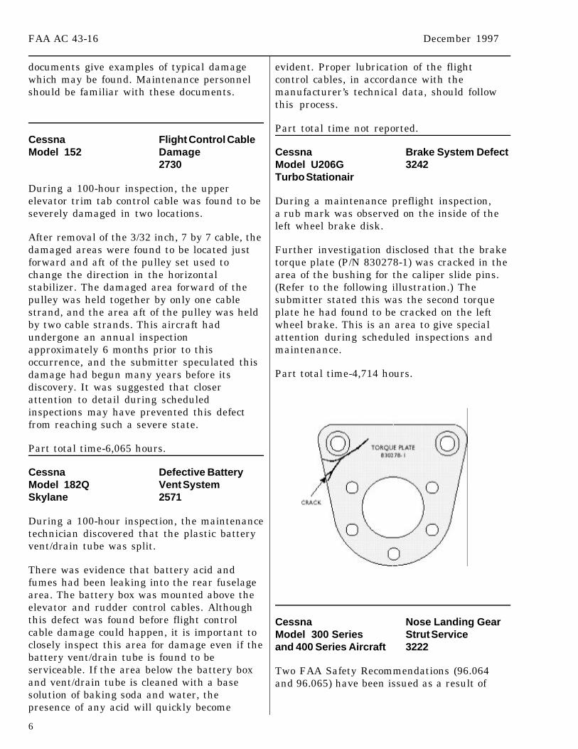
Cessna Brake System DefectModel U206G 3242Turbo Stationair
During a maintenance preflight inspection,a rub mark was observed on the inside of theleft wheel brake disk.
Further investigation disclosed that the braketorque plate (P/N 830278-1) was cracked in thearea of the bushing for the caliper slide pins.(Refer to the following illustration.) Thesubmitter stated this was the second torqueplate he had found to be cracked on the leftwheel brake. This is an area to give specialattention during scheduled inspections andmaintenance.
Part total time-4,714 hours.
Cessna Nose Landing GearModel 300 Series Strut Serviceand 400 Series Aircraft 3222
Two FAA Safety Recommendations (96.064and 96.065) have been issued as a result of

December 1997 FAA AC 43-16
7
a Cessna Model 421B aircraft being operatedwith a flat nose landing gear shock strut.
Due to the flat strut, the nose gear wasjammed in the wheel well and would notextend. This resulted in a landing with thenose gear in the “up” position, and the aircraftsustained substantial damage. Section 4 of thePilot’s Operating Handbook (POH) states thatthe nose gear will not retract into the wheelwell if the shock strut is flat and may cause amalfunction of the retraction system.Chapter 2 of the maintenance manualdescribes the proper servicing of the shockstrut. Proper servicing of the strut is indicatedby 1.37 inches of strut extension with theaircraft on the ground and in a normalattitude.
Proper preflight inspections and maintenanceof the nose landing gear are critical to safeoperation of these as well as other aircraft.
Part total time not reported.
Cessna Main Landing GearModel 414 DefectChancellor 3231
During an annual inspection, the left mainlanding gear door torque tube assembly wasfound to be cracked.
The crack was located adjacent to a weld forthe fork bolt attachment fitting at the aft endof the torque tube (P/N 5045010-19). (Refer tothe following illustration.) The crack wasapproximately .5 inch long, and the submitterstated that corrosion was present. The ServiceDifficulty Program data base contains 42additional entries similar to this report. Manyof those reports related more severe failureswhich resulted in substantial aircraft damageand/or personal injuries. Also, this torque tubeis used on several other Cessna aircraftmodels. Airworthiness Directive (AD) 76-13-07and Cessna “Multi-Engine Service Letter”(SL) ME75-23 deal with this subject.Maintenance personnel should concentratetheir attention on this area during scheduled
inspections and comply with AD 76-13-07 andSL ME75-23.
Part total time-2,844 hours.
Cessna Engine ExhaustModel 414A System DefectChancellor 7810
During a normal maintenance inspection, anexhaust stain was noticed along the weld of anengine exhaust system elbow.
The exhaust system elbow connected to the“Y-fitting” for the Turbocharger wastegatevalve. Closer examination revealed the elbow(P/N K19910299-10) was cracked at theperiphery of both sides of the weld. This partwas constructed of two 45-degree sectionswelded together to form the necessary90-degree radius. This exhaust elbow was an“after market” PMA approved part. Theaircraft had been modified in accordance withthe Ram Aircraft Corporation SupplementalType Certificate (STC) specifying theinstallation of water cooled TeledyneContinental, Model 520 engines. The submitter

FAA AC 43-16 December 1997
8
stated that the original exhaust system elbowwas manufactured from a single piece ofexhaust pipe, and no defects have been foundwith the original equipment part.
The part total time was calculated to beapproximately 1,855 hours.
Cessna Nose Landing GearModel 550 Uplock FailureCitation 3230
It was reported that the nose landing gearcontinually cycled when the gear was selectedto the “up” position. The hydraulic pressure“on” light would illuminate each time the gearcycled.
An inspection of the system disclosed that thenose landing gear strut bearing nut(P/N 5542308-7) had “backed off” allowing thebearing to become loose. This caused the strutto extend beyond limits, and the nose gearuplock hook would not engage. Each time thenose gear came to the full “up” position, theuplock hook failed to engage, the hydraulicpump shut down, and the gear would thendrop out of the wheel well until the hydraulicpump once again engaged.
Part total time not reported.
Cessna Nose Landing GearModel 560 Steering InterferenceCitation 3250
While investigating a reported abnormal noisein the nose wheel well area, a wear mark wasfound on a bracket.
The worn bracket (P/N 5565618-37) is mountedon the left side of the wheel well and is used tosupport one of the nose wheel steering cablepulleys. (Refer to the following illustration.)Also, it appeared there was an exceptionalamount of “slop” associated with the steeringbungee. The submitter speculated that thebracket wear allowed the bungee to drop downand bind on the pulley bracket when the nosewheel “goes full travel” to the left. If notcorrected, this could cause separation of the
pulley bracket from the structure when thenose wheel is moved back to the right position.
Part total time-1,829 hours.
MOONEY
Mooney Propeller InstallationModel M20C 6122Ranger
This aircraft had an Edo Aire (Garwin)three-blade propeller installed in accordancewith Supplemental Type Certificate (STC)SA4529NW.
After 3 hours of operation, the propeller beganto surge 100 to 200 RPM when set to 2,400RPM. After numerous tests, the submitterdetermined the propeller governor was notsupplying a sufficient volume of oil to properlyoperate the propeller. The submitter statedthe STC instructions did not mention the oilvolume required to properly operate thepropeller governor.
Aircraft total time-1,633 hours.

December 1997 FAA AC 43-16
9
PIPER
Piper Engine STCModel PA-12 InstallationSuper Cruiser 7100
The following article was submitted byMr. Raymond Cloutier, Aviation SafetyInspector (Airworthiness), FAA FlightStandards District Office located in Portland,Maine.
During the past 12 months, there have been anincreasing number of FAA Forms 337 reviewedwhich reference installation of a TextronLycoming Model O-320-B2A or -B2B, 160horse-power engine (or some other TextronLycoming model above the original O-320engine) on PA-12 aircraft. The data being usedfor these installations are Supplemental TypeCertificates (STC’s) SA4-519 and SA4-456. STCSA4-519 was held by “H.M. Ruberg” and isnow owned by “McKenzie Flying Service, Inc.”STC SA4-456 is held by Kenmore AirHarbor, Inc. Neither of these STC’s, or theirrevisions, stipulate a model designation of theTextron Lycoming O-320 engine nor do theyspecify “O-320 Series.” STC’s SA4-519 andSA4-456 are applicable ONLY to the originalTextron Lycoming Model O-320 (or O-320-A1Aas it was later redesignated) engine and arenot applicable to any other model in the O-320series.
At this time, there are several PA-12 aircraftoperating with these STC’s that have anengine installed other than the O-320approved by these STC’s. Many owners,operators, and others, having reviewed STC’sSA4-519 and SA4-456, have incorrectlyconcluded that the STC’s are applicable to theO-320 engine series. Any Piper PA-12 aircraftcurrently operating with a standardairworthiness certificate having a TextronLycoming engine installed in accordance withSTC SA4-519 or SA4-456 that is other than theoriginal O-320, 150 horse-power engine may beoperating in an unairworthy condition due to
an unapproved engine installation. Owners,operators, and maintenance technicians areadvised to review their FAA Forms 337 toconfirm their aircraft are in compliance withSTC’s SA4-519 and SA4-456. Some of theseimproper installations may have beenaccomplished by the “field approval” process.Field approvals involving aircraft powerplantsrequire FAA engineering concurrence andmust be coordinated with the local FAA FlightStandards District Office.
Part time not applicable.
Piper Fuel SystemModel PA 20 RestrictionPacer 2820
During takeoff, the aircraft lost engine powerjust after lifting off. The pilot elected toattempt a landing on the remaining 100 feet ofrunway. At the end of the remaining 100 feet,the aircraft “nosed over” and came to rest inan inverted position.
After repair of the structural and sheet metaldamage, an inspection of the fuel systemrevealed the right fuel tank aft outlet fitting(P/N AN840-6D) was completely plugged.(Refer to the following illustration.)The material blocking the outlet fittingappeared to be tightly compacted “dirt” froman unknown source. It was speculated thatover many years sediment from many gallonsof fuel, “dirt,” and other contaminates hadcollected in sufficient quantities to stop theengine fuel supply. The criteria for thisaircraft accident required the right fuel tankto be selected as the sole source of engine fuelsupply.
It would be wise to inspect and clean the fuelsystems of older aircraft at frequent intervalsto eliminate contamination which, if notremoved, could result in an accident.
Part total time not reported.

FAA AC 43-16 December 1997
10
Piper Nose Landing GearModel PA 24 FailureCommence 3230
The pilot reported that the nose landing gearfailed to retract after takeoff. The landing gearcontrol circuit breaker opened, and allattempts to lower the nose gear failed. Thenose gear collapsed during landing.
During an investigation, it was determinedthat while the nose gear was in transit towardthe “up” position, it traveled outside of the“Y-channel.” This caused the gear to attemptto retract in a “side-ways” position, and thecontrol circuit was overloaded. The submitterrecommended the nose gear be checked toensure alignment and condition of the rollerassembly (P/N 14976-15) at every opportunity.
Part total time not reported.
Piper Excessively RichModel PA 24-260 Fuel/Air MixtureComanche 7322
The mechanic/owner/pilot of this aircraftreported that during flight the engine beganrunning rough. The fuel/air mixture wasleaned, and the engine performance improved.After landing, engine power could not bemaintained due to an excessively rich fuel/airmixture.
During an investigation it was found that thefuel servo seal (P/N 2539561) was defective andleaking fuel into the air chamber. Thesubmitter questioned the integrity of the sealand suggested it be closely inspected prior toinstallation. The FAA Service DifficultyProgram data base has one other similar entry.
Part total time-30 hours.
Piper Wing-Walk AreaModel PA 28-161 Structural DamageWarrior 5730
Skin weakness was reported by the pilot in thewing-walk area.
An investigation revealed the reinforcementdoubler, riveted to the lower side of thewing-walk skin (P/N 62061-02), was cracked allalong the butt rib area. The Service DifficultyProgram data base contains 22 other entriesconcerning a defect with this part. These 22reports cover several other aircraft models onwhich these parts were installed. This areadeserves full attention during scheduledinspections.
Part total time-6,547 hours.
Piper Elevator Spar CracksModel PA 31 Series 5521
This is a followup to an article published onpage 14 of the August 1997 edition of thispublication. The additional information wasfurnished by Mr. Scott Myers, Aviation SafetyInspector (Airworthiness), FAA FlightStandards District Office located inMinneapolis, Minnesota.
December 1997 FAA AC 43-16
11
Two reports from a repair station concerningelevator spar cracks were investigated. Bothof the defects occurred on the left elevatorspar of like aircraft. A review of the ServiceDifficulty Program data base revealed anadditional 24 reported cases of elevator sparcracks. A number of these reports indicatethat the defect was discovered duringcompliance with Piper Service Bulletin(SB) 998, and these defects were not visibleuntil the elevator had been removed andmodified in accordance with the SB.
The reporting repair station and the FAAinspector in this case have recommended thisissue be made the subject of an AirworthinessDirective (AD). This recommendation has beenput in the form of an FAA SafetyRecommendation, and at the present time, isbeing processed as a proposed AD. This actionwas prompted by the considerable age of theaffected aircraft and the negative safetyimplications of an in-flight elevator sparfailure.
Part total times not reported.
Piper Fuel Hose FailuresModel PA 31-310C 2820Navajo
During an annual inspection, several fuelhoses were found to be deteriorated andleaking.
The hoses (Aeroquip P/N 601000-8) were usedon the fuel filter and fuel selector valve. Thehoses were very hard and began to leakthrough the braid when they were disturbed.The submitter did not identify how many fuelhoses were defective. When the hoses wereremoved for replacement, the identificationtag marking (“2 Qtr 74”) indicated they hadbeen manufactured in the second quarterof 1974. This would make the hoses over 23years old and far beyond their intended lifelimit. We continue to receive defective hosereports in spite of the numerous articles andother publicity this subject has received overthe past several years. The cost and/or
replacement time involved with flexible hosesshould not deter their removal before theybecome a hazard to safety.
Part total time-2,218 hours.
Piper Ineffective PropellerModel PA 31-325 ControlNavajo 6100
The pilot reported that during cruise flight,the left engine propeller RPM began to decay.The propeller control was advanced, and theRPM remained constant for approximately1 hour. However, without warning, thepropeller went to the “feathered” position.
After a safe landing, maintenance techniciansdiscovered the plug (P/N 71640) inside theengine crankshaft was loose. This allowed oilto bypass the propeller governor. No metalwas found in the engine oil sump or filter.After properly seating the plug, an operationaltest revealed normal propeller operation.It would be a good idea to check this plug forsecurity and proper installation at everyopportunity.
Part total time-2,538 hours.
Piper Engine FailureModel PA 32-300 7414Cherokee Six
During a fatal aircraft-accident investigation,the cause was determined to be a magnetofailure. After takeoff, the aircraft wasoperated for just less than an hour when thepilot reported experiencing engine problems.The aircraft impacted the water after sufferingloss of engine power.
During the accident investigation, it wasdetermined that the left magneto (SlickP/N 6351) had completely failed. The impulsecoupling (P/N M3333) housing was cracked,and one pawl was loose due to a rivet failure.The other pawl was found jammed betweenthe housing and the coupling body. Themagneto drive gear, located in the engineaccessory gear box, had one broken tooth and

FAA AC 43-16 December 1997
12
the intermediate gear had several teethmissing. The engine used in this aircraft wasa Textron Lycoming, Model IO-540. The FAAService Difficulty Program data base containsthree other reports of magneto failures on likeaircraft and engines. All four of these reportsinvolved failure of the left magneto. In two ofthe four cases, engine starting anomalies hadbeen reported prior to magneto failure.Records indicated this magneto had beenoperated for 748 hours.
In another case, the magneto impulse couplingfailed, resulting in engine stoppage. Thismagneto had 1,287 operating hours since new.Severe wear caused the pawls to become looseand jam. The magneto seized with one pawljamming under the other. Another magneto(Slick P/N 6351) was installed and failed aftera few hours of operation.
It was recommended that all owners of PiperPA-32-300 aircraft, equipped with TextronLycoming IO-540 series engines using Slick(P/N 6351) magnetos and Slick (P/N M3333)impulse couplings, perform the followingactions.
Remove and inspect the left magneto (also theright magneto if equipped with an impulsecoupling) if hard starting difficulties occur. Itwas also recommended that the magneto beinspected following each 250 hours ofoperation or any time aluminum “filings” aredetected in the engine oil. Remove and inspectthe impulse coupling, pawl clearance, rotorshaft for dimpling (where the pawl heelstrikes the rotor shaft), and the pawl stop pinin accordance with Unison Industries, SlickAircraft Products, Maintenance and OverhaulManual (P/N L-1363) for the 4300-seriesmagnetos and 6300-series magnetos. Pleasereport all findings by submittingFAA Form 8010-4, Malfunction or DefectReport, if any of these conditions are found.
Information for this report was submitted byMr. Nick Miller, FAA Service DifficultySpecialist, with the Aircraft CertificationOffice located in Chicago, Illinois. At this timethe accident investigation is not complete.
If further pertinent information is reported, itwill be printed in a future edition of thispublication.
Piper Aileron Control CableModel PA 32-301 InterferenceSaratoga 2710
During a scheduled inspection, the aileroncontrol system was binding at one point in itstravel.
Further investigation disclosed that the rightaileron/rudder interconnect clamp wascatching on a broken bracket. The bracket(P/N 62679-00) was located at the forwardattachment point for the wing flap handle. Thesubmitter speculated that the bracket wasbroken by “stepping on the flap handle orexcessive force being applied during retractionand/or extension of the flaps.” Care should betaken to avoid abusive forces when operatingall aircraft systems.
Part total time-1,946 hours.
UNIVAIR
Univair (Stinson) Flight ControlModel 108-1 Column CorrosionVoyager 2701
During a scheduled inspection, the flightcontrol column (P/N 108-3041100) was found tocontain water.
The condensation had accumulated toapproximately one-quarter of a cup. Thecontrol column has a drain hole for theelimination of condensation; however, the holewas plugged. The submitter stated he hadknowledge of another occurrence of this defectwhich resulted in an accident and substantialaircraft damage. The presence of moisturepresents not only the possibility of corrosiondamage, but also damage from the moisturefreezing and causing damage to the controlcolumn.

December 1997 FAA AC 43-16
13
It was recommended that the aluminum plugbe removed from the bottom of the controlcolumn, and the interior be treated with acorrosion inhibiting material.
Part total time-2,456 hours.
HELICOPTERS
BELL
Bell Defective HoistModel 206 Series Cable Cutter
Alignment2500
The information for this article was submittedby Ms. Cindy Lorenzen, an AeronauticalEngineer, with the FAA Aircraft CertificationOffice (ACE-117A) located in Atlanta, Georgia.
During operations using a Breeze-EasternModel BL-16600 hoist, the hoist cable wasfound to be partially severed. Afterexamination of the hoist, the cable cutter wasfound to be misaligned resulting ininterference between the sharp edge of thecutting barrel and the cable.
A Customer Advisory Bulletin (CAB-100-55)has been issued by Breeze-Eastern for allModel BL-16600 series hoists. This hoistmodel is installed as original equipment byBell Helicopter on Model 206 serieshelicopters. This hoist may also be installed inaccordance with Aeronautical AccessoriesSupplemental Type Certificate (STC)SH3191SO on Bell 206A/B series helicopters,STC SR00299AT on Bell 206L serieshelicopters, and STC SR01295AT on Bell 407series helicopters. Breeze-Eastern also holdsan FAA Parts Manufacturing Approval forthese hoists installed on 206L serieshelicopters. The CAB-100-55 requiresinspection of the alignment of the cable cutter,inspection of the cable, and procedures forproper realignment of the cable cutter. A copyof CAB-100-55 may be obtained fromBreeze-Eastern, at telephone number (800)929-1919, or from Aeronautical Accessories, at
telephone number (800) 251-7094. BellHelicopter will issue a separate servicebulletin.
Breeze-Eastern is working on a permanent fixfor this problem. When this informationbecomes available, the FAA will issue anAirworthiness Directive (AD) to mandate acorrection.
Bell Transmission GearModel 206B III Shaft WornJet Ranger 6310
While completing a scheduled inspection, themain rotor transmission gear shaft(P/N 206-040-040-005) was found severelyworn.
Further investigation disclosed that the “sungear” and the gear shaft were both worn farbeyond acceptable limits. The spline on theseparts was approximately 50 percent worn. Thesubmitter speculated the cause of this defectwas the length of time the parts had beeninstalled and a corresponding breakdown ofthe lubricant. The manufacturer’s maintenancemanual requires inspection of these parts at1,500 hour intervals. Since this aircraft hadbeen operated approximately 100 hours peryear in the past, it had been 9 years since theparts had been inspected. It was recommendedthe manufacturer revise the inspectioninterval for the gear shaft and “sun gear” to1,500 hours or 4 years, which ever occurs first.The overhaul limit is 4,500 hours.
Part total time-2,997 hours.
Bell Possible DefectiveModel 214ST Float AssembliesSuper Transport 3212
Bell Helicopter Textron, Inc. has recentlyissued Alert Service Bulletin(ASB) 214ST-97-77, and Air Cruisers, Inc. hasissued Service Bulletin 903-25-02. Both ofthese publications advise that float assemblies(P/N’s 214-052-200-105 and -106) may havebeen manufactured with an incorrectlyinstalled “girt” attachment.

FAA AC 43-16 December 1997
14
The ASB requires that these float assembliesbe returned directly to the Air Cruisers, Inc.for inspection and repair of the “girt”attachments. Air Cruisers, Inc. has establisheda rotating loaner pool to assist operators withquicker turnarounds. Copies ofASB 214ST-97-77 may be obtained uponrequest to Bell Helicopter Textron, Inc.,P.O. Box 482, Fort Worth, TX 76101.
ENSTROM
Enstrom Main RotorModel F28F Transmission WearFalcon 6320
It was reported that the main rotortransmission chip light illuminated at 7 to10-hour intervals after installation of a newtransmission.
The transmission continued to “make metal”until it was finally removed from service. Priorto removal, the transmission generated a pieceof metal that was approximately .25 inch long.According to the submitter, the manufacturerhad suggested the installation of a “lesssensitive chip plug” and stated “metalgeneration was normal break-in wear for thistransmission.” The submitter has experiencedan average life for this transmission of 200 to700 operating hours. The published timebefore overhaul is 1,200 hours.
Part total time-174 hours.
SCHWEIZER
Schweizer Engine FailureModel 269C 8520Engine Textron LycomingModel HIO-360
During an orbit maneuver at 500 feet altitude,a loud abnormal “clunking” sound was heard,and a “jerk” was felt through the airframe. Atthe same time, the engine failed, which
required an immediate forced landing. Bothoccupants were injured, and the helicoptersustained substantial damage.
During the accident investigation, thenumber 4 connecting rod was found protrudingfrom the engine case. Both of the connectingrod crankshaft attachment bolts(P/N LW12596) were broken, and it wasspeculated their failure caused the engine tofail.
The engine had been overhauled inNovember 1996; however, it could not bedetermined if the connecting rod bolts hadbeen replaced at that time.
Part total time not reported.
AMATEUR, EXPERIMENTAL, ANDSPORT AIRCRAFT
REVOLUTION HELICOPTER
Revolution Flight ControlModel Mini 500 Rigging
6200
The information for the following article wasfurnished by Mr. Fred Maupin, Aviation SafetyInspector (Airworthiness) FAA FlightStandards District Office located in Houston,Texas.
As the result of an accident investigation, itwas determined that the flight control rigginginstructions supplied by the kit manufacturermay be inadequate. Physical evidence from theaccident site indicated the possibility thatrigging of the rotor primary flight controls wasnot correct.
Section 7 (Rigging and Balancing) of the kitmanufacturer’s Assembly and MaintenanceManual contains instructions for rigging theprimary helicopter flight controls. Theseinstructions are ambiguous and appear to omitspecific tolerances, limits, measurements,dimensions, and other critical criteria which

December 1997 FAA AC 43-16
15
would ensure safe operation. There are othersections of the maintenance manual,operations manual, and assembly instructionswhich need to be improved.
Some of the helicopter primary flight controlattaching parts were less than standardquality, such as hardware and rod-end fittingsthat had no “witness hole” to inspect forproper thread insertion. This is not acertificated aircraft; however, in the interestof safety, the selection of hardware meetingaviation quality standards and having “doublesecurity” (rod-end jamnuts with safety wireprovisions) for primary flight controls wouldadd very little to the cost of the kit.
A review of the FAA Service DifficultyProgram accident/incident data base revealed12 reports involving this aircraft.
PROPELLERS ANDPOWERPLANTS
ALLISON
Allison Engine FailureModel 250-C20 7313
This engine was installed in a HughesModel 369D helicopter. During flight, theengine failed without warning. A safe run-onlanding was made.
An investigation revealed the engine hadfailed due to fuel starvation. The fuel nozzlescreen was found contaminated with foreignmaterial which severely restricted fuel flow tothe engine. The filter screen was collapsed byexcessive pressure during high engine powersettings just prior to failure.
The fuel nozzle screen is the last of threefilters in the engine fuel system, and there isno bypass system provided. The first filter isin the fuel pump and has an “impendingbypass” indicator light. The second filter islocated in the fuel control and also has a
bypass system; however it does not have anindicator light. The engine maintenancemanual requires a fuel pump bypass valveoperational test be accomplished when thefuel pump filter is replaced as part of the300-hour inspection. It is possible that thisprocedure is not being properly accomplishedduring inspections. The fuel pump bypassvalve operational check identified in theoperations and maintenance manual is acomplete test of the system and not merelyobserving the “impending bypass” light forillumination.
Part total time not reported.
HARTZELL
Hartzell Autofeather FailureModel HC-B5MP-3A 6123
The pilot reported the propeller would not“autofeather” during engine shutdown. Thepropeller was installed on a ShortsModel S360 aircraft.
Disassembly and inspection of the propellerdisclosed the feathering spring (P/N A3496)was broken into seven pieces. This defectdisabled the propeller feathering mechanism.The submitter could offer no cause or cure forthis defect, and no other details werereported.
Part time since overhaul-2,059 hours.
ACCESSORIES
UPDATE ON DEFECTIVE INSTRUMENTAIR FILTERS
In the November 1997 edition of thispublication, we printed an article concerningdefective instrument air filters manufacturedby Rapco. This article gave specific lot andpart numbers which the manufacturersuspected may have been defective. The FAAissued Airworthiness Directive (AD) 97-16-10,

FAA AC 43-16 December 1997
16
dated July 31, 1997, which requireddiscontinuing use of specific instrument airfilters. Please refer to AD 97-16-10, thepreviously mentioned Alerts article, and themanufacturer’s newsletter “Rapco, Inc.Reporter,” dated January 1, 1997, for specificinformation.
Since the previous Alerts article waspublished, two reports were received statinginstrument air filters of the same type andpart number were found defective. Thesefilters (P/N RA-1J4-7) were from lotnumber 02797 which was not included in theapplicability statement in AD 97-16-10. At thepresent time, the FAA is conducting athorough investigation of this situation, andthe results will be published when a resolutionis reached.
Until this problem is resolved, maintenancepersonnel and operators are cautioned toclosely inspect all instrument air filters beforeinstallation and be suspicious of thosepreviously installed.
AIR NOTES
AIRWORTHINESS DIRECTIVES (AD’S)ISSUED IN OCTOBER 1997
AD 84-23-06 R1 Pilatus Britten-NormanModels BN-2, BN-2A,BN-2B, BN-2T, and BN-2AMK. 111 series airplaneswhich required inspectingbrackets, bolts, andbrushings on engines.
AD 86-07-02 R1 Pilatus Britten-NormalBN2A MK.111 serieswhich required inspectingjunction of torque link lugand MLG torque link.
AD 97-20-14 Mitsubishi MU-2Bairplanes which requiredadding information toLimitations Section ofAFM.
AD 97-22-01 Pilatus Britten-NormanBN-2A, BN-2B, and BN-2Tairplanes which requiredinspection of torque linklug and MLG.
AD 97-22-02 Pilatus Britten-NormanBN-2, BN-2A, BN-2B, andBN-2T series airplaneswhich required modifyingupper-engine brackets onwing front spar.
AD 97-22-03 Extra FlugzeugbauEA-300/200 airplaneswhich required installinga seatbelt safety cover.
AD 97-22-08 Pilatus AircraftPC-6/B1-H2, PC-6/B2-H4,and PC-12 airplaneswhich required amendingLimitations Section toAFM.
AD 97-22-09 Dornier Luftfahrt 228series aircraft whichrequired amendingLimitations Section ofOperating Handbook.
AD 97-22-10 Partenavia CostruzioniAeronauticas AP68TPseries which requiredamending LimitationsSection of AFM.
AD 97-22-11 Industrie AeronautichePiaggio P-180 airplaneswhich required amendingLimitations Section ofAFM.
December 1997 FAA AC 43-16
17
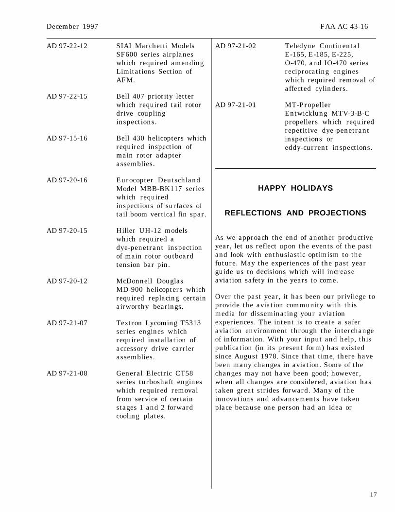
AD 97-22-12 SIAI Marchetti ModelsSF600 series airplaneswhich required amendingLimitations Section ofAFM.
AD 97-22-15 Bell 407 priority letterwhich required tail rotordrive couplinginspections.
AD 97-15-16 Bell 430 helicopters whichrequired inspection ofmain rotor adapterassemblies.
AD 97-20-16 Eurocopter DeutschlandModel MBB-BK117 serieswhich requiredinspections of surfaces oftail boom vertical fin spar.
AD 97-20-15 Hiller UH-12 modelswhich required adye-penetrant inspectionof main rotor outboardtension bar pin.
AD 97-20-12 McDonnell DouglasMD-900 helicopters whichrequired replacing certainairworthy bearings.
AD 97-21-07 Textron Lycoming T5313series engines whichrequired installation ofaccessory drive carrierassemblies.
AD 97-21-08 General Electric CT58series turboshaft engineswhich required removalfrom service of certainstages 1 and 2 forwardcooling plates.
AD 97-21-02 Teledyne ContinentalE-165, E-185, E-225,O-470, and IO-470 seriesreciprocating engineswhich required removal ofaffected cylinders.
AD 97-21-01 MT-PropellerEntwicklung MTV-3-B-Cpropellers which requiredrepetitive dye-penetrantinspections oreddy-current inspections.
HAPPY HOLIDAYS
REFLECTIONS AND PROJECTIONS
As we approach the end of another productiveyear, let us reflect upon the events of the pastand look with enthusiastic optimism to thefuture. May the experiences of the past yearguide us to decisions which will increaseaviation safety in the years to come.
Over the past year, it has been our privilege toprovide the aviation community with thismedia for disseminating your aviationexperiences. The intent is to create a saferaviation environment through the interchangeof information. With your input and help, thispublication (in its present form) has existedsince August 1978. Since that time, there havebeen many changes in aviation. Some of thechanges may not have been good; however,when all changes are considered, aviation hastaken great strides forward. Many of theinnovations and advancements have takenplace because one person had an idea or

FAA AC 43-16 December 1997
18
wondered how something could be donebetter.
As we ponder and project the future ofaviation, we have visions of great changes tocome which now are only a glimmer insomeone’s mind. So, it is with augustanticipation, we look to see what each new daywill present. Challenges and problems are metwith solutions and changes.
The staff of the FAA’s DesigneeStandardization Branch, AFS-640, would liketo take this opportunity to wish all ourreaders and the entire aviation community avery happy, prosperous, and safe holidayseason.
MERRY CHRISTMAS ANDHAPPY NEW YEAR!
PROFESSIONAL RIDER
The following article is being printed with thegenerous permission of the author,Mr. Pete Kelley. I feel sure that we all musthave experiences similar to those related byMr. Kelley, and it seems appropriate,especially at this time of year, to reminisceand realize how we came to this point in life.
Thump, thump, thump, thump. The largesingle cylinder BSA motorcycle waspropelled through the summer morning airas if by the very heart of its youthful rider.It was a Saturday morning in 1971. I was18, high school was over, and my draftlottery number was 318. I was free for lifeit seemed, and I was bound for my friend’shouse to whittle away the day. The soundwaves from the trumpeting exhaustradiated out to all nearby creation, and insome youthful philosophical construct,I believed it communicated what I was. Itprobably did that more accurately thanI ever realized, with most of the neighborsthinking “there’s that fool kid again riding
his loud motorcycle.” The farmers weremowing the second cutting of hay, and thecountry air in up-state New York wasambrosial.
The soft distant thumping encroachedsteadily upon the Malara property,culminating with the rowing of the engineas I wheeled into the driveway. My bestfriend, Pat, came out of the house, and hisolder brother Bobby looked up from underthe hood of his 1965 Chevelle as I picked aprime piece of the sidewalk to park mybike. As I dismounted, the first oil dropstarted to form on the bottom of the enginecasing of the motorcycle. A black, lifelessblood. A picture of sin that might not washout. The drop grew as friendly insults wereexchanged. Bobby had come too close tolosing a race the night before, and hisreputation was on the line. As we talked,the drop of oil continued to grow,stretched, and birthed with velocity.
Mr. Malara stepped out of his shop just asthe oil drop hit his sidewalk, and suddenlyI was thrust back into the school of life.Black and white, right and wrong, one wayand one way only, think ahead, doublecheck, ask if you are not sure, beresponsible for your actions, don’t assumeanything. The details are endless but theconcepts are sound and few.
Mr. Malara was a giant, and I was a gnat.He was an A&P and A.I. of distinction, anaward winning aircraft restorer, aDesignated Examiner, a pilot and thefounder and Chief Instructor of theRiverside School of Aeronautics. He wasforever complaining about some detail ofright and wrong. I was a tinkerer andseldom right. I feared and respectedMr. Malara. I attended his A&P school.I spent much time in his shop and at hiskitchen table. It was with hisrecommendation that I secured my firstairline job with a commuter.
All that happened long ago and far away.In the years that followed I gained muchexperience and some success. I paid my

December 1997 FAA AC 43-16
19
dues and kept the professional faith. I amolder now and the industry has changed.All four of the airlines I have worked forare either out of business or have beenreorganized. Recently, I set out to startover again and having been away from mytools for 8 years, I accepted an entry-levelA&P position performing heavy checkwork. I quit after 1 week because of theunprofessional methods I observed. Theday I quit I returned home to be informedof Mr. Malara’s death.
It took a few days to sink in, and it did notsink in completely until I tried to figureout how old Mr. Malara was when I firstmet him. It turned out that he had been 44,my present age exactly! Suddenly I realizedthat I owed all of my professionalmaintenance standards to him. And thatwith Mr. Malara gone and those of his ilkwith him, it was now up to the mechanicsof my generation, in the afternoon of theircareers, to instill those same professionalstandards in the new technicians enteringthe field. I feel sure that young peopletoday would benefit greatly from one ofMr. Malara’s lectures on why one does notpark a lousy oil-dripping motorcycle onsomeone else’s sidewalk.
We do not convey professionalism by loudtalk or fast work. We do convey that we areprofessional by demonstrating that there isonly black and white, right and wrong, oneway and one way only, by thinking ahead,double checking, asking when we are notsure, being responsible for our actions, andnot assuming anything!
ALERTS ONLINE
This publication is now available through theFedWorld Bulletin Board System (BBS), viathe Internet.
You may directly access the FedWorld BBS attelephone number (703) 321-3339. To access
AC 43-16, General Aviation AirworthinessAlerts, through the Internet, use the followingaddress: “http://www.fedworld.gov/ftp.htm”.This will open the “FedWorld File TransferProtocol Search And Retrieve Service” screen.Page down to the heading “Federal AviationAdministration” and select “FAA-ASI”. The filenames will begin with “ALT”, followed bythree characters for the month, followed bytwo digits for the year (e.g. “ALTJUN96.PDF”).
Also available at this location are the ServiceDifficulty Reports (SDR’s) for the past2 months, which may be of interest.
The Regulatory Support Division (AFS-600)has established a “HomePage” on the Internet,through which the same information isavailable. The Internet address for theAFS-600 “HomePage” is:“http://www.mmac.jccbi.gov/afs/afs600”.Also, this address has a large quantity of otherinformation available. There are “hot buttons”to take you to other locations and sites whereFAA Flight Standards Service information isavailable. If problems are encountered, youcan “E-mail” us at the following address.
If you wish to contact the staff of thispublication, you may do so by any of the meanslisted below.
Editor: Phil Lomax, AFS-640Telephone No.: (405) 954-6487FAX No.: (405) 954-4570 or (405) 954-4748
Internet E-mail address: [email protected]
Mailing Address: FAA ATTN: AFS-640 ALERTS P.O. Box 25082 Oklahoma City, OK 73125-5029
We welcome the submission of aircraftmaintenance information via any form orformat. This publication provides anopportunity for you to inform the general

FAA AC 43-16 December 1997
20
aviation community of problems you haveencountered as well as bringing them to theattention of those who can resolve theseproblems. Your participation in the ServiceDifficulty Program reporting process is vital toensure accurate maintenance information isavailable to the general aviation community.
ELECTRONIC AVAILABILITY OFINFORMATION
In light of the previous article, we solicit yourinput and ideas for the future of thispublication. The electronic information mediahas made available a vast amount ofinformation in a more expedient and efficientmanner. We believe the expanded use of thismedia can bring about the conveyance of safetyinformation in a more efficient and timelymanner.
We are currently distributing approximately28,000 printed copies of this publication eachmonth, and the distribution number continuesto increase. The cost for publishing, printing,and mailing this publication has alsoincreased, and there has been a substantialnegative impact on our budget allotment.
In an effort to save tax dollars and make betteruse of the electronic media, we encourage ourreaders to cancel their printed copysubscription to this publication and use thecomputer to download the monthly issues.(The instructions for downloading the Alertswere given in the preceding article.) We willbe happy to help you if you require furtherassistance. Some of you may not yet have theequipment necessary to receive theinformation electronically, and you arewelcome to continue receiving it in the printedform.
There have been some efforts to charge anannual subscription fee for this publication.So far, these efforts have not been given muchcredence. We will make every effort to keepthis a free-of-charge publication. However, we
need your input and ideas. Would you bewilling to pay a nominal subscription chargefor this publication?
We appreciate your interest in this publicationand the opportunity to serve you. Please offerany comments, questions, or suggestions to usvia any of the means listed in the precedingarticle.
SUSPECTED UNAPPROVED PARTSSEMINAR
As announced in previous editions of theAlerts, the Designee Standardization Branch,AFS-640, will begin presenting the SuspectedUnapproved Parts Seminar. The first seminarwill be held on January 14, 1998, inSacramento, California. The second seminarwill be held on January 28, 1998, inFort Worth, Texas.
Additional seminar dates will be announced inthe Alerts, the Designee Update Newsletter,and on the Internet under FedWorld.gov.You may access the FedWorld BBS directly at(703) 321-3339. You may access the Alertsthrough the Internet, using the RegulatorySupport Division, AFS-600, “HomePage” at thefollowing address.
http://www.mmac.jccbi.gov/afs/afs600
The seminar will discuss the following:
1. What is an approved part? 2. How can approved parts be produced? 3. What is a suspected unapproved part? 4. How is a suspected unapproved part
reported in accordance with FAAOrder 8120.10A, Suspected UnapprovedParts Program, and utilizingFAA Form 8120-11, SuspectedUnapproved Parts Notification?
The cost of this 8-hour seminar will be $60.The seminar may be used for the InspectionAuthorization (IA) renewal training

December 1997 FAA AC 43-16
21
requirement contained in Title 14 of the Codeof Federal Regulations (14 CFR) part 65,section 65.93(a)(4).
The seminar is open to the aviation industry.Anyone wishing to attend may telephone(405) 954-0138. Payment is required in advanceby using VISA, MasterCard, or a check.
FAA FORM 8010-4, MALFUNCTION ORDEFECT REPORT
For your convenience, FAA Form 8010-4,Malfunction or Defect Report, will be printedin every issue of this publication.
You may complete the form, fold, staple, andreturn it to the address printed on the form.(No postage is required.)
SUBSCRIPTION REQUEST FORM
For your convenience, a Subscription RequestForm for AC 43-16, General AviationAirworthiness Alerts, is printed in everyissue.
If you wish to be placed on the distributionlist, complete the form, and return it, in astamped envelope, to the address shown onthe form.

Use this space for continuation of Block 8 (if required).

Federal Aviation AdministrationAFS-640 (Alerts)P.O. Box 25082Oklahoma City, OK 73125-5029
U.S. Departmentof Transpor tationFederal AviationAdministration
Flight Standards ServiceDesignee Standardization BranchP.O. Box 25082Oklahoma City, OK 73125-5029
Official BusinessPenalty for PrIvate Use $300
AFS-640

SUBSCRIPTION REQUEST FORMADVISORY CIRCULAR (AC) 43-16, GENERAL AVIATION AIRWORTHINESS
ALERTS
Please use this request to subscribe to AC 43-16 or to change your address if you are presently on the mailinglist. Once your name has been entered, you will continue to receive this publication until you request your namebe removed or a copy is returned because of an incorrect address.
Because this mailing list is independent of other FAA mailing lists, it is necessary that you notify us when youraddress changes. (Our address is on the following subscription request.) If you are presently receiving thispublication it is NOT necessary to send another subscription request. The following subscription request may beduplicated, as necessary. TELEPHONE REQUESTS WILL ALSO BE ACCEPTED; THE TELEPHONENUMBER IS (405) 954-6487. THE FAX NUMBERS ARE: (405) 954-4748 and/or (405) 954-4570.
AC 43-16 SUBSCRIPTION REQUEST
If you would like to BEGIN receiving AC 43-16, orCHANGE your address, please complete the following:
PLEASE PRINT INFORMATION LEGIBLY,INCLUDE YOUR ZIP CODE, AND THE DATEOF YOUR REQUEST.
NAME:
ADDRESS:
ZIP CODE
DATE:
CIRCLE ONE OF THE FOLLOWING:
1. This is a NEW subscription.
2. This is an ADDRESS CHANGE.
SEND ONLY ONE SUBSCRIPTION REQUEST TOTHE FOLLOWING ADDRESS:
FAA, Regulatory Support DivisionATTN: AFS-640 (Phil Lomax)P.O. Box 25082Oklahoma City, OK 73125-5029
If you require more than one copy of AC 43-16, it may be reproduced.

U.S.Departmentof Transportation
Federal AviationAdministration
Designee Standardization BranchATTN: ALERTS, AFS-640P.O. Box 25082Oklahoma City, OK 73125-5029
AFS-640
Official BusinessPenalty for Private Use $300
BULK MAILPOSTAGE & FEES PAID
Federal AviationAdministration
PERMIT No. G44