Dear member, - XS4ALL Klantenservice
42
Transcript of Dear member, - XS4ALL Klantenservice
Dear member,
This pdf contains translated articles of our Dutch magazine “De Kunstmaan”.Translation for each article is mostly done by the author, using Google Translate. Mostly some corrections are done afterwards. But for sure these translations are not perfect! If something isn't clear please let u know.
Figures are added as much as possible, so the “paper” (Dutch) magazine is not always needed to have at hand.
Internet links mentioned in the articles can also be found at our website; see under menu 'Weblinks' at:www.kunstmanen.net
I hope these translations will help you to understand the Dutch articles.
Rob Alblaswerkgroep [email protected]
Content
page KM page in this pdf
From the Chairman (Preface) 3 4
oproep redacteur 5 7
Weather satellites in Vietnam (29) 6 8
The VCO of the HRPT-decoder 9 11
Correcting mistakes and stashing away 14 19
Testing VCXO's 17 23
Spectrumanalyzer extension to 8 GHz 19 29
bieb 24 37
Report meeting September 8 25 38
Satellite status 26 40
Photo frontpage: Equipment etc. seen at last meeting.

Preface
It was a quiet gathering due to holidays, other events etc. Still nice to see everyone again after the summer.
This summer did not really invite me to get started with the hobby. Because I do not have air conditioning, it is very hot indoors.
From the field I understand that the LNAs of MiniCircuits give a bit more noise because of the heat. The temperature had risen to 85 degrees Celsius.
Also, the decoder trimmer of the VCO due to the heat be had to be more adjusted. Apparently, electronics only work well at room temperature. The adjustment problems must be a thing of the past with a VCXO. In this Kunstmaan a story by Rob how this all works. I have wrote an article on the first measurements of the VCXOs .
At the last meeting Job arranges the helical of Peter Kuiper . Arne simulates a satellite dish and Peter Smits watches.
QPSK receiver
The demand for parts packages has now dried up. A total of 25 packages were distributed . In my receiver I have an output for the spectrumanalyzer (who has not one yet?) . Behind the down converter (700 MHz) is a splitter which divides the signal between the receiver and the spectrumanalyzer there. You can then very nicely see the bandwidth and distance to the noise floor.
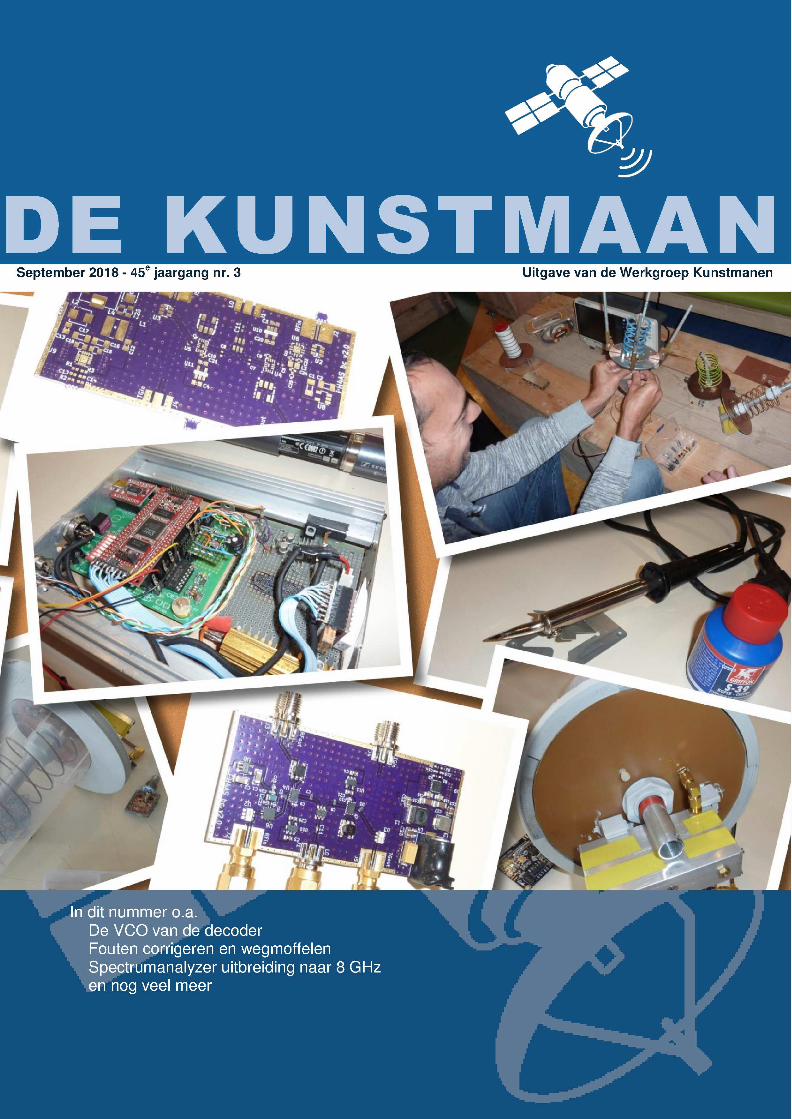
My enclosure therefore had to be a bit bigger and I made it from standard aluminum profiles and aluminum sheets. Drilling the rectangular and elliptical holes is a challenge. In the real world, these holes are punched with metal punches (do you call them that?) .
Everything in one enclosure made from standard aluminum profiles on the side.
The reception was very bad. Turns out there are still a problem for me everything from a single external 5V power feed. Fortunately, this problem was easy to solve. However, the enclosure can not close yet because, depending on the satellite, I still have to turn the trimmer.
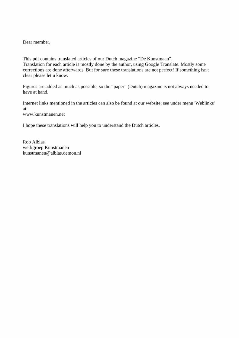
At this moment I have an oscilloscope permanently attached to the receiver to look at the consistency diagram . Of course, it would be much nicer if you have a small display on the receiver where you can see this. Search on eBay for "OLED display", now an AD converter and a microcontroller or FPGA.
Example of a constellation viewer designed by Oleg . See also http://www.sat.cc.ua/page6.html

8 GHz
The first steps are on the 8 GHz . Job describes in this Kunstmaan a band converter for the 8 GHz . On twitter you can see first results from other amateurs. Just look for Jean-Luc Milette
https://twitter.com/LucMilette
With a dish of 170cm he can already receive satellites in the 8 GHz . Should we be able to do this with a smaller dish?
And Stefan DK3SB has designed a down converter:
https://twitter.com/thasti
And in order to maintain knowledge of the many GHz levels, we have taken a subscription to the UKW. Our librarian Paul writes about this.
Nimeto
Job receives live reception at the May meeting demonstrated from the square in front of the canteen. Inquiries have shown that we also have access to the roof. We then suffer much less from the trees. We could (temporarily) put down an antenna here. We do need a long cable down. Something to keep in mind.
Further in this Kunstmaan an article by Rob to brush away lines and thus to a nicer picture to come. Fred is writing his 29th story from Vietnam again and I can tell you that he will be at the New Year's meeting again on January 5th! Much reading pleasure desired!
The next meeting is on 10 November. This meeting will also focus on the attic clearance. So take the things you do not do anything with, maybe make someone else happy with it.
On November 3rd we have another stand on the Day for the RadioAmateur , this time in Zwolle. Come all!

Jaargang 45 nr. 3 | DE KUNSTMAAN 1
EDITOR WANTED
Fred van den Bosch Summary Wanted: a new editor for De Kunstmaan Preface After the stopping of Harry Arends as editor, I have taken over that task for the time being. And in itself it is absolutely fun work. You can have your own influence on certain areas. I did that myself, for example, by making another page 2. A life-size problem are my bad eyes. Left is not much more to do: is only slowly getting worse. On the right, my ophthalmologist expects a cataract operation this year. A quarter of an hour work, a month without contact lenses. This is of course a far from ideal situation. Making De Kunstmaan also benefits from stability. And that is now far away because I can be forced to stop at any time.
In short, the Werkgroep is looking for an editor for De Kunstmaan.
Time estimate I can imagine that people think that this is days of work. No, no, absolutely not. If you have some experience with Word and follow the procedure, which I have set up and is also extensively available on paper, then it is very easy. If all items are available, everything putting in columns in the KM and a quick first markup takes less than 1 hour. Then make all articles detailed, photo on front and back page, table of contents etc. about 2-3 hours. Then the whole is checked by the board and perhaps some time must be spent on some correction work. Training Of course we do not immediately throw a new editor into the deep. He / she is trained at a distance. I will - if my eyes allow it at that moment - remain available for questions and help. One option is to make a Kunstmaan as a test, for example, without the pressure of a deadline. If you want more information - of course without any obligation - you can always email me or the board or make a chat at a meeting with the board. Visiting the meetings is absolutely not necessary for the editorship. I can only come when I am on vacation. But that has not proven to be a problem in practice.
2 DE KUNSTMAAN | Jaargang 45 nr.3
WEATHER SATELLITES IN VIETNAM
(29)
Fred van den Bosch Summary My experiences with weather satellites etc. in Vietnam. APT Due to various circumstances, there is no new PC yet. So no news to report. WxToImg For those who missed it: Les Hamilton has put the very useful piece below on the GEO-Subscribers forum. "All pages of the WXtoImg website were deleted early this summer, denying enthusiasts the opportunity to download the popular software.
Now, enthusiast Kevin Schuchmann has created a clone of the site called WXtoImg Restored, which you can access at the following URL [1] In addition to providing downloads of the software, Kevin also reveals his (previously registered) Professional Edition Upgrade Key, which will open all the program's advanced features for use. It is not usual to divulge such details, but as the author of WXtoImg has not responded to queries for some three years, and his WXtoImg website no longer exists, it seems only reasonable to release it to the Public Domain." HRPT / QPSK It has been very hot here for a long time, so I did not want to change anything on the roof. E.g. I have just pushed forward pulling new cables to my room below. The installation is still on the first floor with the cables outside through the window. The receiver is now provided with a front plate, sent by Peter Kuiper and printed by my regular photo shop. Despite all my warnings beforehand, initially at the wrong size. But I am a good and regular customer, so that was done neatly without further nagging. For this they just got a little longer time and the outlined measurements of the closet. I have only not encountered a nice housing for the LEDs here, so I have to do something for that myself. Then the front plate will be more neatly against the cupboard.
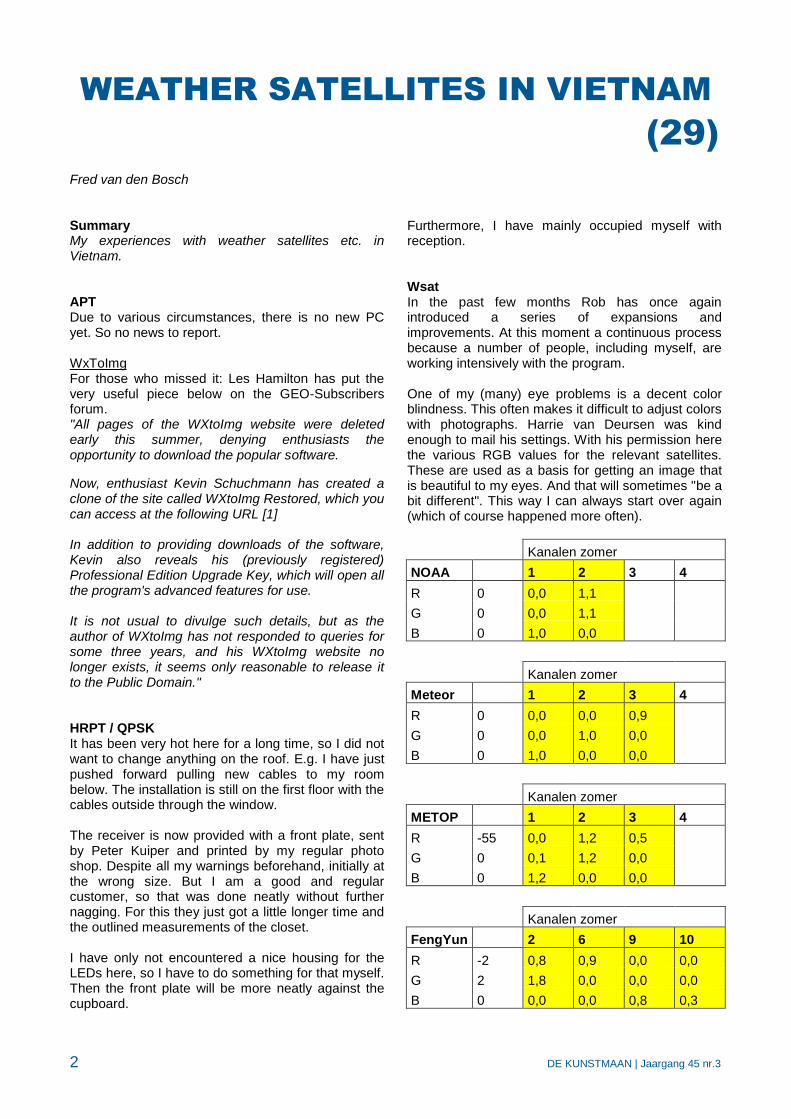
Furthermore, I have mainly occupied myself with reception. Wsat In the past few months Rob has once again introduced a series of expansions and improvements. At this moment a continuous process because a number of people, including myself, are working intensively with the program. One of my (many) eye problems is a decent color blindness. This often makes it difficult to adjust colors with photographs. Harrie van Deursen was kind enough to mail his settings. With his permission here the various RGB values for the relevant satellites. These are used as a basis for getting an image that is beautiful to my eyes. And that will sometimes "be a bit different". This way I can always start over again (which of course happened more often).
Kanalen zomer
NOAA 1 2 3 4
R 0 0,0 1,1
G 0 0,0 1,1
B 0 1,0 0,0
Kanalen zomer
Meteor 1 2 3 4
R 0 0,0 0,0 0,9
G 0 0,0 1,0 0,0
B 0 1,0 0,0 0,0
Kanalen zomer
METOP 1 2 3 4
R -55 0,0 1,2 0,5
G 0 0,1 1,2 0,0
B 0 1,2 0,0 0,0
Kanalen zomer
FengYun 2 6 9 10
R -2 0,8 0,9 0,0 0,0
G 2 1,8 0,0 0,0 0,0
B 0 0,0 0,0 0,8 0,3

3 DE KUNSTMAAN | Jaargang 45 nr.3
These are only the summer settings. I do not think that, given my place of residence, I will have to do something with the winter settings, although I will test it by that time. The top of the photo passes through the Himalayas. One of the recent extensions to wsat is that you can now store three different versions for each satellite. With me that is: 1. Harrie’s settings 2. My own settings (sometimes deviate somewhat) 3. Experimental AutoHotKey As I already announced last time, I am working on creating a script via AHK [2], with which I can easily make small changes to the photo in Wsat. For the photographers: in terms of idea a very simple version of the Development-module of Lightroom [3]. Script In the AHK script I can adjust the photo via Despeckle, Channel Map and Luminance and if necessary save the new values for the next time. These are the screens that normally appear via the menu options. All necessary screens for adjustment are placed next to each other. You can easily change between the different settings in this way and immediately see the consequences of the adjustments for the entire photo. Despeckle I always start with this and see if this really improves. If not, the option is disabled again. Unfortunately, I have not succeeded in getting Despeckle working through the checkbox. You must use the key combination, which is in the AHK field on the right of the photo on the next page. Destrip is standard in Wsat because, according to Rob, this gives the best results. Channel Map The RGB values of the image can be adjusted on this screen. After each change you have to click on <Redraw> to execute the change and see if there is what you hope will happen. If the result is worth the effort, the setting can be saved. Luminance Via the <Lum.Thr> button, the default value for luminance is set automatically on both sides of the histogram. Personally, I find that if you shift the right value a little further to the left (you can also click on the graph) or give Lmax a lower value, the image becomes lighter and therefore more beautiful. But it is also a matter of taste. It is certainly a setting to experiment with. This script is also available. Send an email.
Of everything Radio perception Perseids For those who also want to look at other types of reception this may be something [4]. NASA Pioneer 10, 11 & 12 tires digitize There are some new developments in this project and there is even something of a piece of photo. See [5] References [1] WxToImg clone, see website [2] AutoHotKey for startup wsat and xtrack, see website [3] Adobe Lightroom, see website [4] Radio perception Perseids, see website [5] Digitizing NASA tapes, see website

4 DE KUNSTMAAN | Jaargang 45 nr.3

The VCO of the decoder. A problem with the (A)HRPT decoder is that it must be able to synchronize at different bit rates. NOAA, Metop and Fengyun all have their own bit rate, which unfortunately can not easily be derived from a single frequency. See the table below.
satellite bit rate note
NOAA, Meteor 0.6654 Mb / s split-phase
Metop 2,333 Ms / s QPSK, 1 symbol = 2 bits Eg: 2,333 Ms / s corresponds to 4,666Mb / s.
Fengyun-3A, B 2.8 Ms / s
Fengyun-3C 2,6 Ms / s
The decoder must synchronize to this bit stream, which is done with the aid of a PLL.
A part of the PLL is the VCO; the central frequency of that VCO must be (after division) as close as possible to the bit rate of the satellite to be decoded. The PLL is then able to lock and the VCO frequency(after division) is exactly equal to the bit rate. This is necessary to properly extract the bits.
In the first version of the decoder, the central frequency was obtained as good and as bad as it was with a divider from a VCO at about 20 MHz. A deviation of a maximum of 139 kHz, switching from one satellite to another, was unavoidable, which means that the VCO for several satellites had to be adjusted a bit by hand.
In [1] a solution has been described for this, using frequency multipliers that are present in the FPGA. Through a combination of frequency multiplication and division, the final frequency can be brought much closer to the ideal value. This reduced the maximum deviation to approx. 1 kHz, just enough to switch between all types of decoders without re-adjustment.
Yet this is not the ideal solution yet. Due to temperature changes the frequency may deviate too much so that the trimmer has to be turned again.
In order to solve the VCO problem permanently, I started looking at other possibilities. One is to use a VCXO: Voltage Controlled Xtal Oscillator. Oscillators based on a crystal are much more stable than an LC or RC oscillator. They can be tuned, albeit a little, so a voltage-controlled Xtal oscillator can be realized.
There are then a number of issues that need to be taken into account:
• The oscillator must be able to follow the frequency shift due to the Doppler effect.
• From the crystal oscillator the desired frequency has to be very accurately divided to the different bit rates because that oscillator can only be tuned a little bit. The deviation of 1 kHz mentioned above is far too much.
• The VCXO must be easy to make or available as a module.
An important point is how much the oscillator can be tuned, or what the frequency range is. For a 20 MHz VCXO +/- 100ppm is given, which corresponds to +/- 2 kHz; oscillators on other frequencies give approximately similar ppm results.
Doppler. If the Doppler shift in the received signal, due to the approach / removal of the satellite, is greater than what a VCXO can adjust, then we can forget the VCXO solution. A simple calculation gives the following:
The satellite turns around the earth in about 90 minutes. The length of the track is approx. 45000 km:
radius earth = 6367 km + altitude orbit = 800 km gives a total radius for the satellite orbit of 7167 km; with this the circumference becomes: 7167 * 2 * π = ca.45000km.
The speed of the satellite is 45000 / 1.5 = 30000 km / hour = 8.33 km / sec.
To simplify further calculations, the Doppler shift can be determined in case the satellite comes straight to us. In reality, that is (fortunately) not the case, and the shift will be less.
For the Doppler shift the following approach can be used:
1 + v / c
with v the speed of the satellite and c the speed of light of approx. 300000 km / sec
The Doppler shift thus becomes a factor of 1+ (8.33 / 300000) = 1.000028, thus a deviation of 0.000028 = +28 ppm.
If the satellite moves away from us then the same Doppler shift occurs, but then in a negative sense. So the total deviation of the received frequency is +/- 28 ppm. A VCXO with a tuning of +/- 100 ppm is more than sufficient.
The Doppler shift can be seen equally hard on the received bit rate (in ppm), so for example for Metop the deviation is +/- 28 ppm * 2.33 MHz = +/- 65 Hz.
For NOAA: +/- 28 * 0.6654 = +/- 18.6 Hz.
Assuming a VCXO operating at 20 MHz, the deviation is here: 28 * 20 = +/- 560 Hz. That is the minimum required control range of the VCXO in Hz.
Note that in reality the deviations are less because the satellite does not come straight to us (although for a satellite that is just above the horizon and will pass at high elevation it will be close). As the satellite passes, the Doppler shift will become less and will increase again in a negative sense after passing.
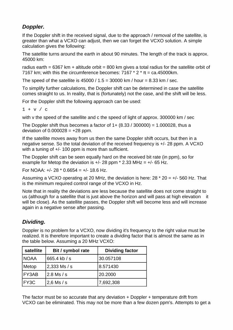
Dividing. Doppler is no problem for a VCXO, now dividing it's frequency to the right value must be realized. It is therefore important to create a dividing factor that is almost the same as in the table below. Assuming a 20 MHz VCXO:
satellite Bit / symbol rate Dividing factor
NOAA 665.4 kb / s 30.057108
Metop 2,333 Ms / s 8.571430
FY3AB 2.8 Ms / s 20.2000
FY3C 2,6 Ms / s 7,692,308
The factor must be so accurate that any deviation + Doppler + temperature drift from VCXO can be eliminated. This may not be more than a few dozen ppm's. Attempts to get a
integer dividing factor by using a VCXO with different frequency will give odd factors for other cases, and in addition, the choice of well-available VCXO frequencies is very limited.
The question is therefore how the dividing factor as mentioned above can be realized as close as possible. In principle, that is very simple; eg for NOAA: divide the VCXO first by 200000, then multiply by 6654. This can be simplified: / 100000 * 3327
In practice, large multiplication factors are a problem. In the used FPGA there are a number of multipliers (so-called DCM, Digital Clock Manager) with which a maximum of a factor of 32 can be realized (see [1]).
There is, however, a different and actually much simpler method of making these weird dividing factors, namely with a so-called fractional divider.
Fractional divider. A normal frequency divider consists of a counter that has the desired number of steps. For example, an 8-divider consists of a counter that counts from 0 to 7 and then starts again.
Every time the counter starts again, a pulse is generated, so there is 1 output pulse on 8 input pulses: an 8-divider. See fig. 1, at the top.
Instead of increasing the counter by 1, this can also be done with a different number, eg 3. The 8-counter then runs as follows:
0 3 6 1 4 7 2 5 0 ....
Note that after 6 9 would follow but after 7 the counter starts again, hence after 6 1 follows. Likewise follows after 7 2 and after 5 follows 0.
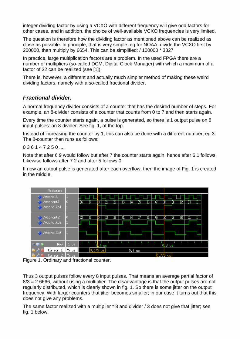
If now an output pulse is generated after each overflow, then the image of Fig. 1 is created in the middle.
Figure 1. Ordinary and fractional counter.
Thus 3 output pulses follow every 8 input pulses. That means an average partial factor of 8/3 = 2.6666, without using a multiplier. The disadvantage is that the output pulses are not regularly distributed, which is clearly shown in fig. 1. So there is some jitter on the output frequency. With larger counters that jitter becomes smaller; in our case it turns out that this does not give any problems.
The same factor realized with a multiplier * 8 and divider / 3 does not give that jitter; see fig. 1 below.
A fractional divisor can be written in formula form as follows (repeated execution after each input pulse):
t: = t + n;
if t> = m then
t: = t - m;
pulse: = 1;
else
pulse: = 0;
end if;
The dividing factor is m / n. In the example above, m = 8 and n = 3.
If n = 1 this is a normal divider.
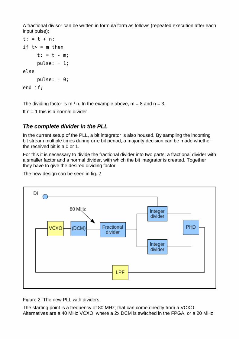
The complete divider in the PLL In the current setup of the PLL, a bit integrator is also housed. By sampling the incoming bit stream multiple times during one bit period, a majority decision can be made whether the received bit is a 0 or 1.
For this it is necessary to divide the fractional divider into two parts: a fractional divider with a smaller factor and a normal divider, with which the bit integrator is created. Together they have to give the desired dividing factor.
The new design can be seen in fig. 2
Figure 2. The new PLL with dividers.
The starting point is a frequency of 80 MHz; that can come directly from a VCXO. Alternatives are a 40 MHz VCXO, where a 2x DCM is switched in the FPGA, or a 20 MHz
VCXO in combination with a 4x DCM. In all cases the final input frequency for the divider is 80 MHz.
satellite Bit / symb.
speed Required divider
Fractional part
Normal div. part
Total divider Dev.
NOAA / Meteor
665.4 kb / s 120.228432 526/140 32 120.228569 0.75 Hz
METOP 2.33 Ms / s 34.285717 30/14 16 34.285713 0.25 Hz
FY3AB 2.80 Ms / s 28.571428 100/49 14 28.571428 0 Hz
FY3C 2.60 Ms / s 30.769232 200/91 14 30.769232 0 Hz
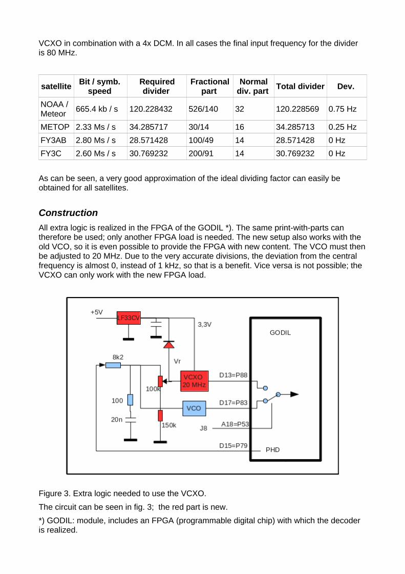
As can be seen, a very good approximation of the ideal dividing factor can easily be obtained for all satellites.
Construction All extra logic is realized in the FPGA of the GODIL *). The same print-with-parts can therefore be used; only another FPGA load is needed. The new setup also works with the old VCO, so it is even possible to provide the FPGA with new content. The VCO must then be adjusted to 20 MHz. Due to the very accurate divisions, the deviation from the central frequency is almost 0, instead of 1 kHz, so that is a benefit. Vice versa is not possible; the VCXO can only work with the new FPGA load.
Figure 3. Extra logic needed to use the VCXO.
The circuit can be seen in fig. 3; the red part is new.
*) GODIL: module, includes an FPGA (programmable digital chip) with which the decoder is realized.
The VCXO's that we have found all work on 3.3V power supply, while the decoder works on 5V. Although the absolute maximum supply voltage for the VCXO is 7V, and therefore 5V supply is not impossible, it is better to maintain the normal supply voltage. With an extra voltage regulator, eg an LF33CV, the 3.3 V is made from 5 V. This regulator requires very little voltage drop (at least 0.7 V) and can therefore be connected to the 5 V. As a result, the power consumption is very low and the regulator does not have to be cooled.
The voltage divider 100k / 150k is needed because the central frequency is reached with a control voltage of approx. 1.6 V, while the phase detector in the PLL generates nominally 2.5V. Without this voltage divider, the PLL is "crooked", and the bits will not be optimal extracted. The central voltage can be adjusted with the potentiometer; unfortunately there is a lot of spread on the control voltage of various VCXOs with which the nominal frequency is obtained.
The diode between the control voltage and 3.3V prevents the control voltage from becoming too high; it can be 5 V while the control voltage of the VCXO may not exceed 0.7 V above the supply voltage.
The VCXO is connected to a separate input pin of the GODIL; I have left the old VCO for a while yet. With a jumper (J8) you can choose between the 2 VC(X)O's. With a future print for the decoder, the old VCO will disappear; there is actually no reason to keep it.
The VCXO of 20 MHz I have used is of the type:
Kyocera, KV7050B20.0000C3GD00
available at (among others) Digi-Key for only approx. 3 euros. As mentioned, 40 MHz and 80 MHz are also possible.
The LF33CV regulator is also almost for nothing; 1.5 euros or so.
Note that this is an experimental setup. The old VCO will disappear so that the VCXO can be connected to pin D13, and jumper J8 is not needed. Furthermore, the PHD output of the GODIL, which has a symmetrical block voltage at optimal setting, does not go beyond approx. 4V, so that the average voltage behind the filter is a maximum of approx. 2V. This leaves little room to optimally adjust a VCXO with a slightly higher nominal control voltage (eg 1.85 V). The reason for the low voltage on PHD is that the FPGA on the GODIL gives a maximum of 3.3V, which is boosted to 5V (ideally) with a special pullup FET. If necessary, an extra buffer can provide a solution.
The construction can easily be done on the existing print, using the experiment field. See fig. 4. We are also working on a new print in which besides the VCXO there is also room for another USB module (that of Adafruit). This is faster; moreover, the Sparcfun USB interface, which is now used, is not or difficult to obtain.

Figure. 4. The decoder print with attached VCXO.
Results The decoder works with the VCXO at least as good if not better compared to the old LC-VCO. The PLL already locks if there is hardly any constellation diagram to be seen on the receiver (in other words: if the demodulator only just locks). The Doppler shift can be seen very nicely at the control voltage.
At one point I started to "miss" something about my recorded images. In [2] I reported disturbances from the rotor motors, resulting in the decoder getting out of the lock with accompanying noise stripes through the image. Those engine interferences are still there, seen on the constellation diagram, but the new PLL with VCXO does not give a peep. That gives me a very big improvement. It is possible that other disturbances, eg from GSM masts, will also have less influence on the recording.
Incidentally, it is better to try and filter out errors as much as possible. Particularly with QPSK, a series of incorrect pixels can occur with each failure. That is always better than
getting out of the lock of the decoder, but still.
Generator. With the small control range of the VCXO, the generator now gives a problem. This generator is only intended to generate a bit stream for each type of satellite, so that the decoder and software can be tested. The bit rate of the generator is not very accurate; the generator was therefore not suitable to precisely regulate the VCO. With the VCXO there is nothing more to arrange, but it is still useful to be able to use the generator.
The generator is already working on a crystal oscillator of 49.152 MHz, which is mounted on the GODIL (see fig. 4).
By now using the same trick, with fractional dividers, the bit rate can be made very accurately. This adapted generator is added in the same FPGA load.
For the loads, see [3].
[1] Development decoding Fengyun. De Kunstmaan 2017, nr. 3, page 12. "Different bitrates"
[2] My first picture. De Kunstmaan 2018, no. 2, page 10
[3] FPGA loads: http://www.alblas.demon.nl/wsat/hardware/hardware2.html#download
Correcting mistakes and stashing away. Summary.
Discussed are ways of how errors in received data from satellites are translated into picture-errors, and how they can be removed or hidden
When receiving weather satellites, it is important to reproduce the transmitted bit stream as well as possible with the aid of receiver and decoder. In the first instance, that is something for the hardware; that is still being worked on. If the hardware is optimized and there are still bits of error, then there is still something to do with the help of software. With QPSK (METOP, Fengyun), a limited number of errors can be corrected because additional correction bytes are included here. This is the Reed Solomon coding, already mentioned in [1].
If that does not help, then one more thing remains: try to "hide away" the mistakes.
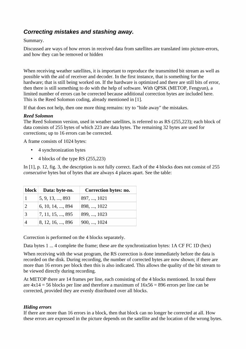
Reed Solomon The Reed Solomon version, used in weather satellites, is referred to as RS (255,223); each block of data consists of 255 bytes of which 223 are data bytes. The remaining 32 bytes are used for corrections; up to 16 errors can be corrected.
A frame consists of 1024 bytes:
4 synchronization bytes
4 blocks of the type RS (255,223)
In [1], p. 12, fig. 3, the description is not fully correct. Each of the 4 blocks does not consist of 255 consecutive bytes but of bytes that are always 4 places apart. See the table:
block Data: byte-no. Correction bytes: no.
1 5, 9, 13, ..., 893 897, ..., 1021
2 6, 10, 14, ..., 894 898, ..., 1022
3 7, 11, 15, ..., 895 899, ..., 1023
4 8, 12, 16, ..., 896 900, ..., 1024
Correction is performed on the 4 blocks separately.
Data bytes 1 ... 4 complete the frame; these are the synchronization bytes: 1A CF FC 1D (hex)
When receiving with the wsat program, the RS correction is done immediately before the data is recorded on the disk. During recording, the number of corrected bytes are now shown; if there are more than 16 errors per block then this is also indicated. This allows the quality of the bit stream to be viewed directly during recording.
At METOP there are 14 frames per line, each consisting of the 4 blocks mentioned. In total there are 4x14 = 56 blocks per line and therefore a maximum of 16x56 = 896 errors per line can be corrected, provided they are evenly distributed over all blocks.
Hiding errors If there are more than 16 errors in a block, then that block can no longer be corrected at all. How these errors are expressed in the picture depends on the satellite and the location of the wrong bytes.

A distinction must be made between HRPT on one hand and Meteor / METOP / Fengyun on the other:
HRPT: data bytes at a fixed location in the frame (1 frame per line). There are no steering bytes.
Meteor / METOP / Fengyun: location of data byte is determined by control bytes (multiple frames per line are required)
An error in a control byte may result in missing a piece of data, or the data will be incorrectly interpreted. A control byte is eg the code word that indicates whether the data placed behind it belongs to the image data or whether it is other data. (see [1], p. 11) In the overview below also the case that the decoder is out of sync is added.
HRPT Meteor METOP / Fengyun
out-sync stripe Stripe or nothing (stripe or) nothing
Error data byte speckle speckle speckle
Driver-byte error (n / a) stripe stripe A speckel can be stashed away by comparing the brightness of a point with its surrounding points. A bright point in a dark environment does not normally occur in an image; if that is the case then wsat can replace that point with one of the surrounding points. In Preferences, tab Algos', it is possible to set at 'Despeckle limits' how big the difference in brightness must be to be recognized as a "stash away" error. Here 2 numbers are used:
the surrounding points must have approximately the same brightness (difference under a specified limit)
difference in brightness of the point with the surrounding points must be above a certain value (difference above another specified limit)
See fig. 1, 'Despeckle limits'.
Figure 1. Part of 'Algos' tab of Preferences, where the 'Despeckle' parameters can be modified.
With hiding error-strips it is first important to know how these streaks appear. Out-sync
HRPT: In that case, the bits are shifted in the serial bitstream. When the shift is 1 bit, all numbers increase or decrease by a factor of 2. In addition, a bit of the neighboring channel shifts in the word of the channel which is shown; the channels are alternately passed on. This explains the stripes.
Meteor: Meteor has a second sync word in the data stream. If that is not recognized then the start of a line can not be determined. Parts of the line can then be bit-shifted with the same result as with HRPT, or the whole line will fall away.
Metop / Fengyun: Here the loss of a line part will take place earlier. The bitstream contains codes that indicate which data we are dealing with. Mutilation of these codes means that the subsequent data is not recognized as the data we want to use.
Error in a data word: With all satellites this always gives a speckle.
Error in a steering byte (eg code word) At HRPT there is no steering byte, so this case does not apply.
With Meteor only the 2nd sync word is important. If there is a limited number of bit errors in it then this has no influence, otherwise you get the same effect as with out-sync. Currently, wsat accepts 3 incorrect bits in this 8-byte sync word.
METOP: Here it depends on which steering byte is mutilated. If it concerns the code with which the type of data is indicated, then you get the same effect as with 'out of sync'. If it is a number that indicates where the data of a line starts in the data part of the frame, then a shift of bits can occur: an error strip.
Fengyun: Again, there is a code word that indicates what kind of data it is. Furthermore, just as with Meteor a 2nd sync word is used and thus with mutilation the same effect occurs.
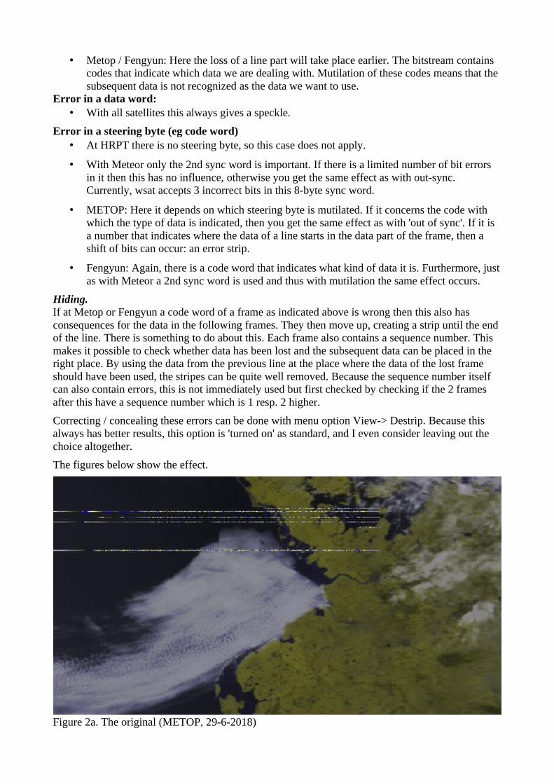
Hiding. If at Metop or Fengyun a code word of a frame as indicated above is wrong then this also has consequences for the data in the following frames. They then move up, creating a strip until the end of the line. There is something to do about this. Each frame also contains a sequence number. This makes it possible to check whether data has been lost and the subsequent data can be placed in the right place. By using the data from the previous line at the place where the data of the lost frame should have been used, the stripes can be quite well removed. Because the sequence number itself can also contain errors, this is not immediately used but first checked by checking if the 2 frames after this have a sequence number which is 1 resp. 2 higher.
Correcting / concealing these errors can be done with menu option View-> Destrip. Because this always has better results, this option is 'turned on' as standard, and I even consider leaving out the choice altogether.
The figures below show the effect.
Figure 2a. The original (METOP, 29-6-2018)
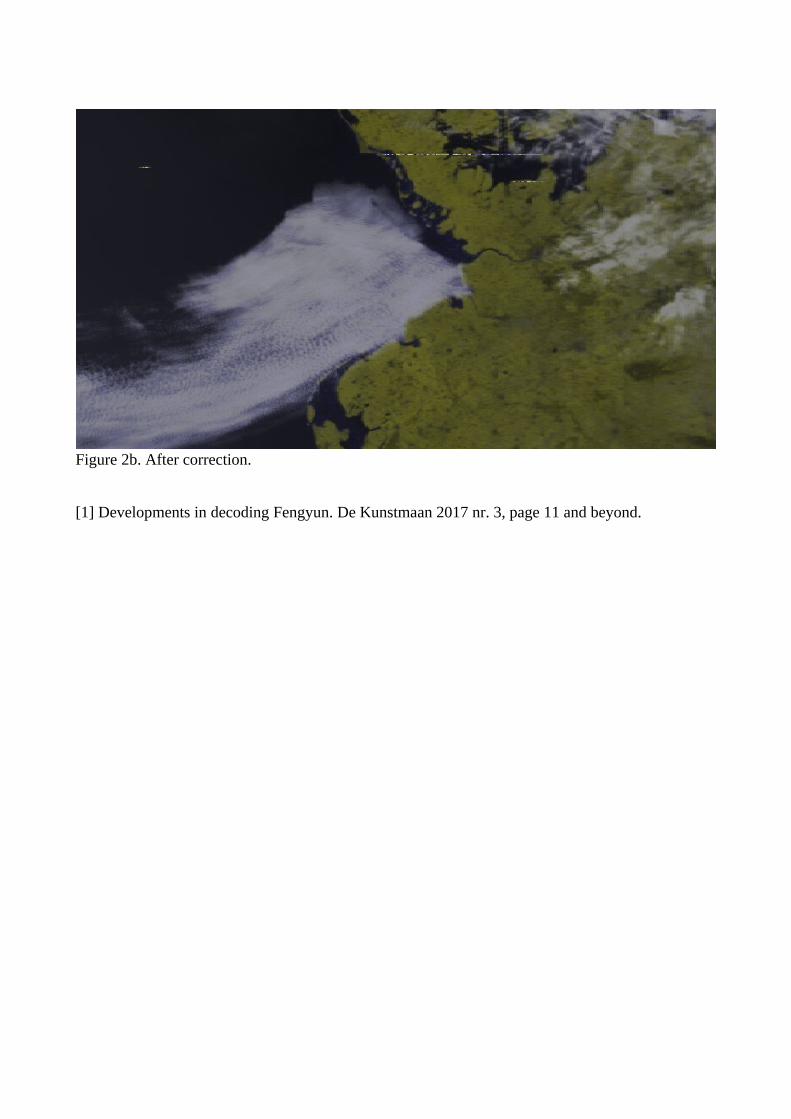
Figure 2b. After correction.
[1] Developments in decoding Fengyun. De Kunstmaan 2017 nr. 3, page 11 and beyond.
Testing the VCXO's
Summary
This article describes how VCXOs are tested.
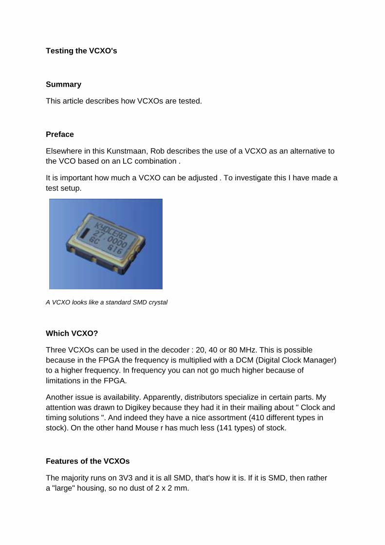
Preface
Elsewhere in this Kunstmaan, Rob describes the use of a VCXO as an alternative to
the VCO based on an LC combination .
It is important how much a VCXO can be adjusted . To investigate this I have made a
test setup.
A VCXO looks like a standard SMD crystal
Which VCXO?
Three VCXOs can be used in the decoder : 20, 40 or 80 MHz. This is possible
because in the FPGA the frequency is multiplied with a DCM (Digital Clock Manager)
to a higher frequency. In frequency you can not go much higher because of
limitations in the FPGA.
Another issue is availability. Apparently, distributors specialize in certain parts. My
attention was drawn to Digikey because they had it in their mailing about " Clock and
timing solutions ". And indeed they have a nice assortment (410 different types in
stock). On the other hand Mouse r has much less (141 types) of stock.
Features of the VCXOs
The majority runs on 3V3 and it is all SMD, that's how it is. If it is SMD, then rather
a "large" housing, so no dust of 2 x 2 mm.

The prices can vary considerably . The models programmed by the manufacturer
(eg Silicon Labs) on frequency are hundreds of euros, the cheapest are only a few
euros.
But what it's all about is what they call the Absolute Pull Range (APR). According to
the manufacturer, this varies between the plus minus 20 and
200 ppm ( parts per million ).
For example, if you look at the datasheet of the 40 MHz from Abracon ( Digikey part
number 535-9349-1-ND, Abracon part number ASVV-40.000MHZ-N102-T), they call
it a " pullability " of about 100ppm . At 40 MHz you would therefore get a deviation
from plus to minus 4 kHz.
Time to start testing and see if this is correct.
We selected three VCXOs that we went to test.
VCXO Part number APR Format Supplier
VCXO 20MHz 478-7012-1-ND 100 7x5mm Kyocera
VCXO 40MHz 535-9349-1-ND 100 7x5mm Abracon
VCXO 80MHz 631-1463-ND 50 5.15x3.35mm IDT
Test setup
Three VCXOs , on the left the 80 MHz, soldered upside down on printed circuit board. The voltage is
set with the potentiometer. The 3V3 regulator is soldered to the connector with capacitor.
VCXO
The VCXO is set to a certain voltage with a potentiometer. I measure it with a
multimeter. I have chosen to go from 0 to 3V3 in increments of 0.1V.
Connections of the VCXO. This is the same for the three types:
pin 1: Vc , the voltage that the VCXO sets to frequency
pin 2: not connected
pin 3: GND
pin 4: the output
pin 5: not connected
pin 6: the power supply 3V3
Frequency counter
This is an old HP 53181A frequency counter. This measures up to 225 MHz .
GPS reference
The frequency counter is controlled with a 10 MHz GPS reference (Timo's design,
written in the past).
Software
Pictures say more than words. Instead of Excel, I used a Python script to create a
graph.
I save the measured values in a csv file . Below are the first five lines of this file:
19996410; 0 19996455; 10 19996513; 20 19996600; 30 19996747; 40
For the semicolon the frequency is in Hz , after the semicolon the control voltage (in
Volts) multiplied by 100. So 0.1 Volt is 10 Volts in the csv-file .
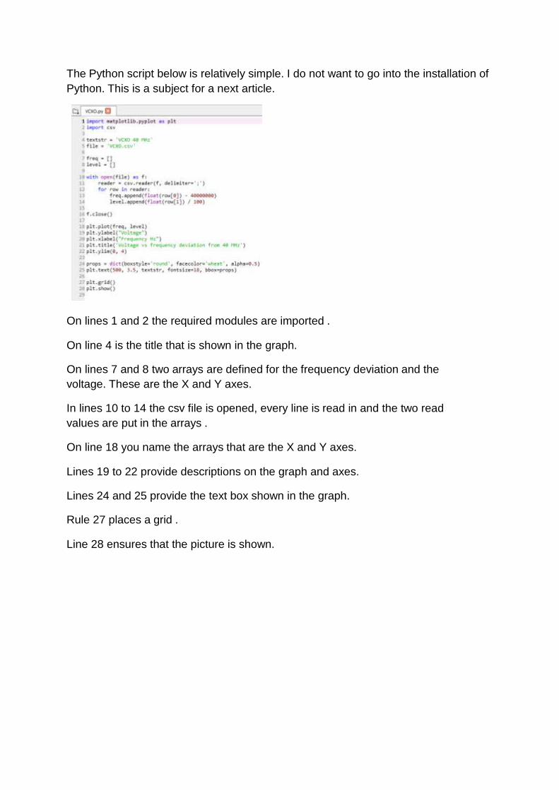
The Python script below is relatively simple. I do not want to go into the installation of
Python. This is a subject for a next article.
On lines 1 and 2 the required modules are imported .
On line 4 is the title that is shown in the graph.
On lines 7 and 8 two arrays are defined for the frequency deviation and the
voltage. These are the X and Y axes.
In lines 10 to 14 the csv file is opened, every line is read in and the two read
values are put in the arrays .
On line 18 you name the arrays that are the X and Y axes.
Lines 19 to 22 provide descriptions on the graph and axes.
Lines 24 and 25 provide the text box shown in the graph.
Rule 27 places a grid .
Line 28 ensures that the picture is shown.
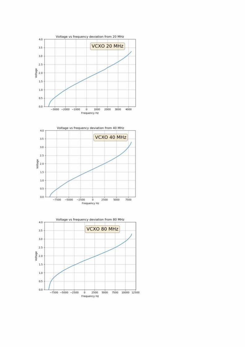
If you look at the graphs, you will see that the specified pullability is amply achieved in
practice. Furthermore, I think it is a "guaranteed minimum", where you always have a
piece will sit up in practice.
Conclusion
It was still useful to do these measurements because it says much more than a
number in a datasheet. In a subsequent test, I want to fully automate measuring by
controlling my power supply from the computer and reading the frequency from the
computer. This is a subject for a next article.

Spectrum analyzer extension to 8GHz Job de Haas PH4AS
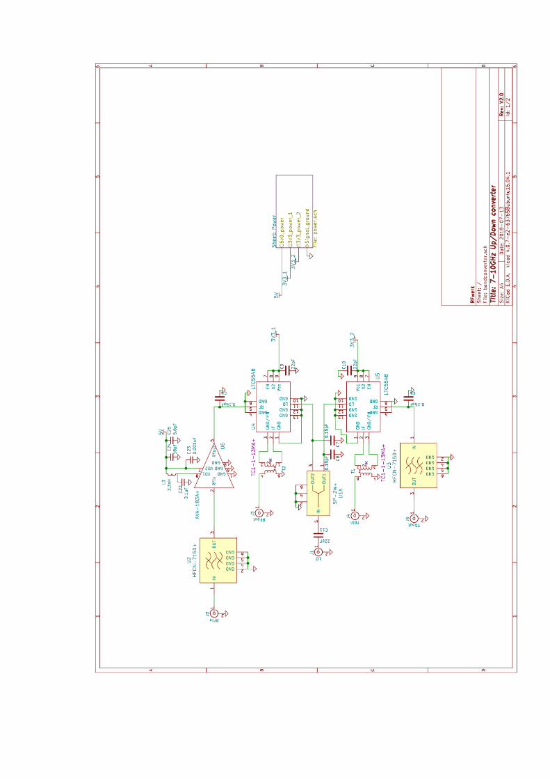
For the building and testing of filters and antennas for HRPT reception, I gratefully used the possibilities of my spectrum analyzer (SA) with tracking generator (TG) (a Advantest R3361A). This works up to 2.6GHz For the new challenge of reception around 8GHz, I really wanted to have a device that would help me with that. Unfortunately, the price of equipment that works at that frequency can be quite high, so I went looking for an alternative. Great inspiration was of course the band converter from Harrie van Deursen who had raised his SA from 0-1GHz to 1-2GHz. Below I describe a number of steps that I have gone through and choices I made for a converter that can convert 0-3GHZ to 7-10GHZ so that the measuring range comes within reach. The core of the converter is simple: take 2 mixers and an LO at a suitable frequency (eg. 7GHz), mix up the signal of the TG, pass it through the component to be measured and mix the resulting RF signal down again with the same LO .
Mixer
My search started with looking for mixers. Minicircuits and Analog Devices are big names. For example with the SIM-14LH + or the HMC220 or HMC553. But Linear Technologies (now owned by Analog Devices) also has several. One of these covers the area of 2-14GHz: the LT5548. Unlike the other mixers, this is an active mixer that needs a power supply, but can also work with a lower level LO input (0dBm). In addition, the mixer has a doubler on the LO input. This allows a lower LO frequency to be used, which can be cheaper (eg. an ADF4351 at 3.5 GHz). After some further searching, I discovered that the mixer is also used in an open source VNA project [1]. Looks like someone who has a lot more experience than me in this area, so that gave me some confidence that this could be a suitable mixer. Later I also discovered a homemade LNB for 8GHz [2] with this mixer.
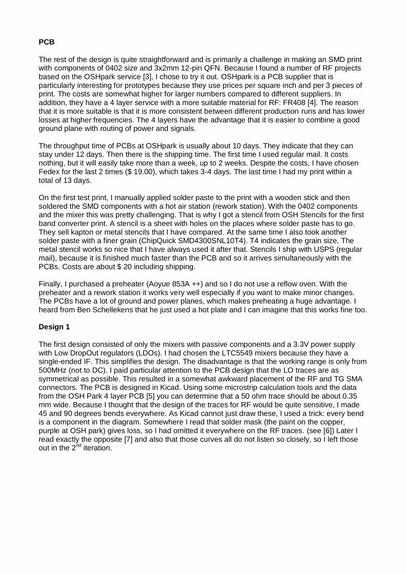
PCB
The rest of the design is quite straightforward and is primarily a challenge in making an SMD print with components of 0402 size and 3x2mm 12-pin QFN. Because I found a number of RF projects based on the OSHpark service [3], I chose to try it out. OSHpark is a PCB supplier that is particularly interesting for prototypes because they use prices per square inch and per 3 pieces of print. The costs are somewhat higher for larger numbers compared to different suppliers. In addition, they have a 4 layer service with a more suitable material for RF: FR408 [4]. The reason that it is more suitable is that it is more consistent between different production runs and has lower losses at higher frequencies. The 4 layers have the advantage that it is easier to combine a good ground plane with routing of power and signals. The throughput time of PCBs at OSHpark is usually about 10 days. They indicate that they can stay under 12 days. Then there is the shipping time. The first time I used regular mail. It costs nothing, but it will easily take more than a week, up to 2 weeks. Despite the costs, I have chosen Fedex for the last 2 times ($ 19.00), which takes 3-4 days. The last time I had my print within a total of 13 days. On the first test print, I manually applied solder paste to the print with a wooden stick and then soldered the SMD components with a hot air station (rework station). With the 0402 components and the mixer this was pretty challenging. That is why I got a stencil from OSH Stencils for the first band converter print. A stencil is a sheet with holes on the places where solder paste has to go. They sell kapton or metal stencils that I have compared. At the same time I also took another solder paste with a finer grain (ChipQuick SMD4300SNL10T4). T4 indicates the grain size. The metal stencil works so nice that I have always used it after that. Stencils I ship with USPS (regular mail), because it is finished much faster than the PCB and so it arrives simultaneously with the PCBs. Costs are about $ 20 including shipping. Finally, I purchased a preheater (Aoyue 853A ++) and so I do not use a reflow oven. With the preheater and a rework station it works very well especially if you want to make minor changes. The PCBs have a lot of ground and power planes, which makes preheating a huge advantage. I heard from Ben Schellekens that he just used a hot plate and I can imagine that this works fine too. Design 1
The first design consisted of only the mixers with passive components and a 3.3V power supply with Low DropOut regulators (LDOs). I had chosen the LTC5549 mixers because they have a single-ended IF. This simplifies the design. The disadvantage is that the working range is only from 500MHz (not to DC). I paid particular attention to the PCB design that the LO traces are as symmetrical as possible. This resulted in a somewhat awkward placement of the RF and TG SMA connectors. The PCB is designed in Kicad. Using some microstrip calculation tools and the data from the OSH Park 4 layer PCB [5] you can determine that a 50 ohm trace should be about 0.35 mm wide. Because I thought that the design of the traces for RF would be quite sensitive, I made 45 and 90 degrees bends everywhere. As Kicad cannot just draw these, I used a trick: every bend is a component in the diagram. Somewhere I read that solder mask (the paint on the copper, purple at OSH park) gives loss, so I had omitted it everywhere on the RF traces. (see [6]) Later I read exactly the opposite [7] and also that those curves all do not listen so closely, so I left those out in the 2nd iteration.
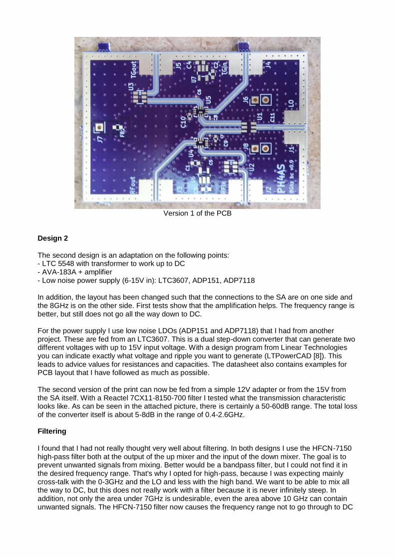
Version 1 of the PCB Design 2
The second design is an adaptation on the following points: - LTC 5548 with transformer to work up to DC - AVA-183A + amplifier - Low noise power supply (6-15V in): LTC3607, ADP151, ADP7118 In addition, the layout has been changed such that the connections to the SA are on one side and the 8GHz is on the other side. First tests show that the amplification helps. The frequency range is better, but still does not go all the way down to DC. For the power supply I use low noise LDOs (ADP151 and ADP7118) that I had from another project. These are fed from an LTC3607. This is a dual step-down converter that can generate two different voltages with up to 15V input voltage. With a design program from Linear Technologies you can indicate exactly what voltage and ripple you want to generate (LTPowerCAD [8]). This leads to advice values for resistances and capacities. The datasheet also contains examples for PCB layout that I have followed as much as possible. The second version of the print can now be fed from a simple 12V adapter or from the 15V from the SA itself. With a Reactel 7CX11-8150-700 filter I tested what the transmission characteristic looks like. As can be seen in the attached picture, there is certainly a 50-60dB range. The total loss of the converter itself is about 5-8dB in the range of 0.4-2.6GHz. Filtering
I found that I had not really thought very well about filtering. In both designs I use the HFCN-7150 high-pass filter both at the output of the up mixer and the input of the down mixer. The goal is to prevent unwanted signals from mixing. Better would be a bandpass filter, but I could not find it in the desired frequency range. That's why I opted for high-pass, because I was expecting mainly cross-talk with the 0-3GHz and the LO and less with the high band. We want to be able to mix all the way to DC, but this does not really work with a filter because it is never infinitely steep. In addition, not only the area under 7GHz is undesirable, even the area above 10 GHz can contain unwanted signals. The HFCN-7150 filter now causes the frequency range not to go through to DC
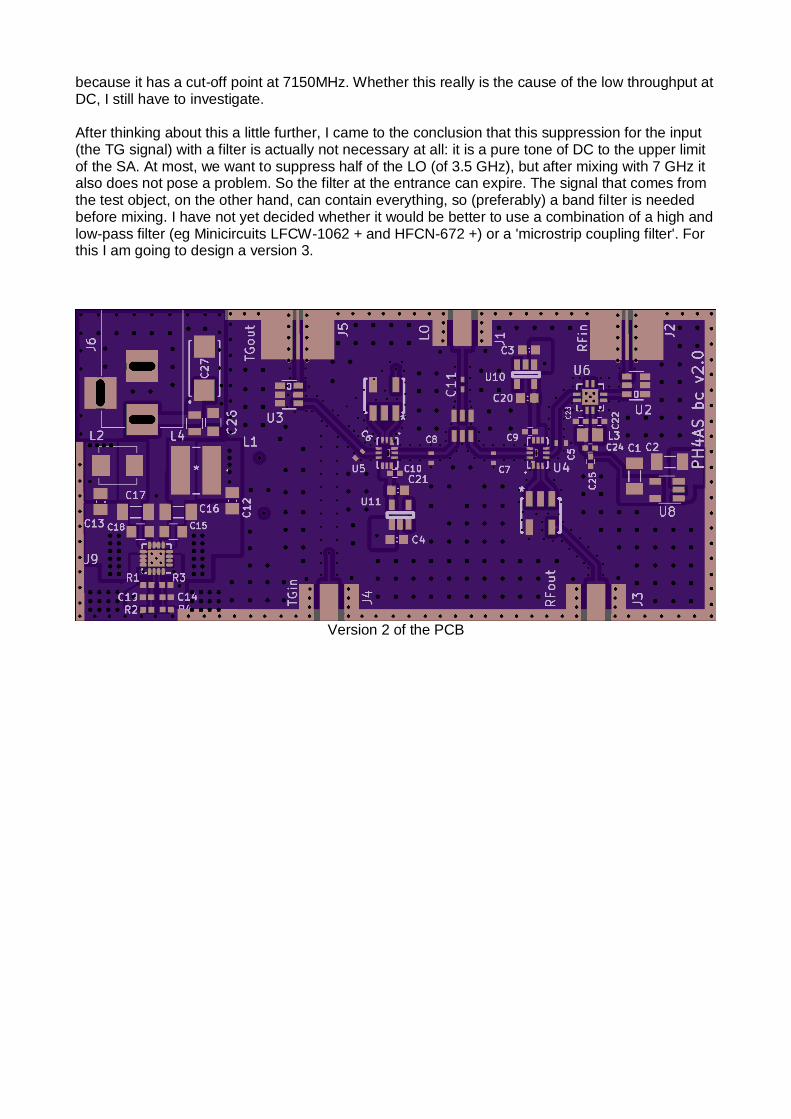
because it has a cut-off point at 7150MHz. Whether this really is the cause of the low throughput at DC, I still have to investigate. After thinking about this a little further, I came to the conclusion that this suppression for the input (the TG signal) with a filter is actually not necessary at all: it is a pure tone of DC to the upper limit of the SA. At most, we want to suppress half of the LO (of 3.5 GHz), but after mixing with 7 GHz it also does not pose a problem. So the filter at the entrance can expire. The signal that comes from the test object, on the other hand, can contain everything, so (preferably) a band filter is needed before mixing. I have not yet decided whether it would be better to use a combination of a high and low-pass filter (eg Minicircuits LFCW-1062 + and HFCN-672 +) or a 'microstrip coupling filter'. For this I am going to design a version 3.
Version 2 of the PCB

Measurement of a Reactel filter from 7.8GHz to 8.5GHz


References
[1] https://hackaday.io/project/26213/logs [2] https://www.loetlabor-jena.de/doku.php?id=projekte:xconv:start [3] http://hforsten.com/improved-homemade-vna.html [4] https://www.isola-group.com/products/all-printed-circuit-materials/fr408/ [5] https://docs.oshpark.com/services/four-layer/ [6] https://twitter.com/_ph4as_/status/986006516783235074 [7] https://twitter.com/HarmonInst/status/974406236308303872 [8] http://www.analog.com/en/products/ltc3607.html#product-tools

From the Library
Paul Baak
Summary: Some thoughts from our Librarian.
Dear people,
How hot and dry this summer was . Oh, what was it is hot and dry. And do you already know that it was hot and dry? There was no escaping for weeks on TV and in the newspapers. I thought it was just great. Anyone who could grumble at our hobby had a desert dry throat and could not say anything. Or got crashed under a stack of cooling fans. I just could go along. Great. Next year again please.
Our club has a subscription to UKW Berichte. It appears 4 times a year .Thanks to Job de Haas for the hint. Nice magazine. Apart from a few articles on 480 MHz ( here it seems slow DC) these boys do not care about a Gigahertz more or less. Two is minimum and I also saw 47 or 250 GHz come along. The club received from Herman ten Grotenhuis a collection of old UKW Berichte and also Dubus'sen, a similar magazine. For him and also others who preceded him: a Honorable Mention. It has also inspired me. I donate to the Werkgroep Kunstmanen:
• USB Toolbox, DVD• Software Defined Radio, book, B Kainka• Kunstmatige Intelligentie, book, Bert van Dam• Mouse Interfacing with USB and PS2, book, S. Bernhoeft• Elektronische filters zonder stress, book, Dietriech en Zantis Information at the librarians desk at the meetings.
Soldering, who did not grow up with solder? Recently my 30 watt soldering iron came into short power. So I got me a poker of 100 Watt at the building market and it does a lot better on a large copper surface. The next problem was oxidation of tin, the surfaces and soldering points. And then you need flux, the doping for every soldering iron. Alibaba has at a few euros some resin for sale, but unfortunately with a delivery time of 2 months and then you are at home with 20 kg of it. So I went back to the hardware store and found there an acid free agent (6 euros) for copper waterpipes. The crazy thing is: that is also called S-39. Which I still know as old means from my childhood because with it have poisoned my first soldering iron. And that was because SantaPappa added it with the best intentions with a soldering iron. This one S-39, however, is completely different, it is intended for copper water pipes and says to be innocent. Why it is not then renamed to something else I do not understand, because this creates confusion. Peter Smits collapsed when I presented the bottle with the inscription S-39 at the meeting. Not necessary. The new stuff is doing well and is odorless and acid-free. There is also a flux for stainless steel. It is called S-39 too of course . Spectrum analyzers, traditionally unaffordable. The high altar of the signal transmission now comes into reach of us ordinary people. In the Elektor of this month a review of 3 of them. The most important of the article is the preview, in other words: what should you pay attention to when purchasing. The price (from 1300 to 3200 euros) is not the only criterion! The contestants are: Siglent SSA3021X, Rigol DSA832E and Peaktech 4130. They are standalones so they do not lean on usb and a PC. Remarkable: the second harmonic in this article is three times the basic wave, not twice. And so on. I think they get second harmonic (= first overtone) confused.
And then the important points of interest: screen and key size, ease of operation, bandwidth, noise, self-disturbance, lower limit frequency, tracking generator, step size, fan noise and I am not yet halfway. Even if you want a completely different type buy then this article is a must-read, to learn what to be aware of. I hope for a next one article, then with the PC-usb ones, because of the weight and size of these non-PC types.
Recently I purchased at the meeting: a DIL crystal oscillator of 100 MHz, just to see if I can see the harmonics on my faithful analog TV. At the manufacturer site I did not find the type number so I suspected a clone or counterfeit. A good neurotic never gives up, so I immediately mailed the manufacturer and expressed my concern. Not needed. The thing was original but End of Life. The difference between original product or more or less clone is sometimes difficult to see and with our projects that need quality components you can not doubt about quality.
So I'm working on a technical catching up. I want to know and perform at least as much or better than you all. So if you get overtaken bluntly in the coming period that will certainly be done by
your librarian

Report members meeting 8 September 2018. Summary: Report of our meeting at September 8. Opening by the chairman. There are just 16 persons present, probably because of other events and holidays. In the previous meeting, Ben had taken old stuff he wanted to get rid of, there will be a follow-up in November. Also stuff set available by ex-members will be made available.
As far as the parts package for the receiver is concerned: the interest "dries up". There is still some activity for the decoder; there will be a new print. Harry Arends is working on it. The GODILs for this are still available. The new print will include a faster USB interface, and there is room for the new VCXO instead of the VCO.
There is not much movement in the area of the 8 GHz. “Someone” seems to have made a down converter.
Ben is working on a program with which filters-on-print can be calculated. For high frequencies (8 GHz) Teflon-print is not really necessary; losses on FR4 board are a bit bigger but not insurmountable.
A mistake has crept into the Newsletter; Estec and Dag van de Radioamateur is of course in 2018, not 2017.
In 2019 GEO will once again organize a Darmstadt excursion. If that continues, we may try to place a table for that day with some information about our working group.
Instead of LRIT on MSG (which is now switched off), which we could use as a test signal, the Russian GLONASS (at 1602 MHz) could be usable. It is located in a high orbit, which means that a transfer takes a long time (with a single aim of the dish for about 2 hours).
Setting the agenda No comments. Administrative affairs Editorship: Fred is currently editor for our magazine, but because of his eye problems we are looking for another editor. See elsewhere in this Kunstmaan. Satellite status Given by Arne, see elsewhere in this Kunstmaan. Any other business Job: Has the band converter adjusted so that it can be fed from the spectrum analyzer. Paul:
• we now have a subscription to “UKW Berichte”, so available through the library. • Unfortunately, the Estec open day is already full. • For soldering parts on a large surface, he uses S-39. Not to be confused with the
old and very aggressive S-39; the new variant is acid-free! Strangely, the name is the same.
Peter Smit: asks if we can visit Estec as a group. That may be looked at. He also notes that filters and so forth that are included in the dish must actually be lightweight. It must all be "lifted" by the rotors. Fons indicates that with a short, low-loss coax cable, you do not have to hang the filter directly on the helix in the dish. Elmar mentions the Meteorology technology world expo, on 8, 9 and 10 October in Amsterdam. It's free, but you must register with: https://meteorologicaltechnologyworldexpo.com/en/ Ben: is experimenting with an OLED display, possibly as a replacement for the 3-segment display of the decoder. There is now an Arduino with FPGA; tools are web-based, so no programs need to be installed. He has also made a housing for the receiver, using alu-profile for the sides; front and back are ordered and delivered to size. Problem then remains the making of rectangular holes etc. for the display. Closing Rob Alblas (secretary AI)

Arne van Belle, as of September 14, 2018 POLAIR APT HRPT Orbit/remarks
(MHz) (MHz)
NOAA 15 137.620 1702.5 morning/afternoon, HRPT weak
NOAA 18 137.9125 1707.0 early morning/late afternoon
NOAA 19 137.100 1698.0 afternoon/night
FengYun 3A none 1704.5 AHRPT 2.80 Msym/s
FengYun 3B none 1704.5 AHRPT 2.80 Msym/s
FengYun 3C none 1701.3 AHRPT 2.60 Msym/s
FengYun 3D none 7820.0 X-band afternoon MPT 60 Mbps
Metop-A off(137.100) 1701.3 LRPT/AHRPT 2.33 Msym/s
Metop-B none 1701.3 Only AHRPT 2.33 Msym/s
METEOR M N1 off(137.100 LRPT) 1700.0 Black image
METEOR M N2 137.100 LRPT 1700.0 LRPT on / MHRPT on
NPP none 7812.0 X-band HRD 15 Mbps
JPSS-1 none 7812.0 X-band HRD 15 or 30 Mbps
NOAA 15, 18 and 19 are the last satellites that still broadcast APT.
The LRPT signal from METEOR M N2 can be received with an SDR dongle.
NPP (NPOESS Preparatory Project) and JPSS-1 (NOAA-20) only transmit on the X-band with 15 Mbit /
s. A tracking dish with a diameter of 2.4 meters is recommended !
FengYun 3A, 3B and 3C broadcast AHRPT, which can only be received with the new QPSK receiver
from Harrie and Ben. This AHRPT is not entirely according to the standard so that even a Metop
AHRPT receiver is not suitable for the FY-3 series!
FengYun 3C also has a data rate other than 3A and 3B and broadcast on X-band with LHCP.
Rob Alblas has expanded his GODIL decoder and can now demodulate HRPT, Meteor HRPT, METOP
and FY3A / B and FY3C in the 1700 MHz band!
FY-3D was launched on November 15th, but this satellite, just like NPP and JPSS-1, only broadcasts
on the X-band!
Douglas Deans mentions that on December 6, the Meteor M N2-2 may be launched as the successor
to the M N2-1 which was lost at launch. (LRPT / MHRPT)
GEOSTATIONAIR APT (SDUS)/PDUS Orbital position/remarks
(MHz) (MHz)
MET-11 (MSG-4) 1691 LRIT 1695.15 HRIT 0 degrees W, operational
MET-10 1691 LRIT 1695.15 HRIT 9.5 degrees W, RSS parallel operation
MET-9 1691 LRIT 1695.15 HRIT 3.5 degrees E, RSS
MET-8 geen LRIT - 41.5 degrees E, IODC
GOES-E (no. 16) 1686.6 GRB 1694.1 HRIT 75.2 degrees W via Eumetcast
GOES-W (no. 15) 1691 LRIT 1685,7 GVAR 135 degrees W via Eumetcast
GOES 14 1691 LRIT 1685,7 GVAR 105 degrees W, Backup
GOES 13 1691 LRIT 1685.7 GVAR 60 degrees W, Backup
GOES 17 89.5 degrees W, in test phase
Elektro-L2 1691 LRIT 1693 HRIT 78 Degrees E, via Eumetcast
MTSAT-1R 1691 LRIT 1691 HRIT 140 degrees E, Backup for MTSAT2
MTSAT-2 1691 LRIT 1687.1 HRIT 145 degrees E, via Eumetcast
Himawari-8 geen LRIT geen HRIT Operational, via HimawariCast and Eumetcast
Himawari-9 no LRIT, no HRIT, Backup for 8
FengYun 2E - - 86.5 degrees E
FengYun 2F - - 112.5 degrees E, Backup
FengYun 2G - - 105.5 degrees E

FengYun 2H - - 79 degrees E, test phase
Fengyun 4A 1697 LRIT 1681HRIT 99.5 degrees E, Operational
Launches:
MetOp-C Launch 7 November
Meteor M N2-2 Launch 3 December
Elektro-L no 3 Launch 22 October, possibly again a signal at 1691 MHz!
Unfortunately, DVB-S and most "DVB-S2 without VCM" receivers are no longer usable for
EUMETCast. With a special driver some recent DVB-S2 receivers can still be made suitable for Basic
Service Only. (only the TBS-5980 and Skystar 2 eXpress HD, unfortunately this does not apply to the
Skystar HD USB box)
The signal at 10 degrees east has a larger bandwidth and is therefore weaker than before.
Recommended dish diameter is 80-90 cm for Basic Service and at least 120 cm for High Volume
Service 1 and 2
The 2nd EUMETCast transponder TP2 is on 11387.500 MHz Horizontal and transmits HVS-2. The
Symbol Rate and mode is the same as HVS-1 (33000 kSym / s DVB-S2, CCM mode, MODCOD
16APSK2 / 3).
For good reception the same applies as for HVS-1, in good weather a 90 cm dish is sufficient but you
actually need 120 cm.
Users can receive GOES 16 data live on TP1 / HVS-1 after requesting. Unfortunately this is in NetCDF
format. In addition to SNAP, EUMETCastView by Hugo van Ruys can display this format.
http://hvanruys.github.io/
David Taylor has written a GOES ABI Manager for Goes 16 and 17 NetCDF data:
http://www.satsignal.eu/software/GOES-ABI-Manager.html
Due to "congestion" in the TV satellite world, we see that more and more transponders are being
used on Eutelsat 10A. For optimum signal quality (SNR) you have to turn the LNB (Skew) so that
vertical transmitters are attenuated as much as possible. A LNB of moderate or poor quality can
suddenly give problems if it has poor attenuation for the vertical signals. This is called Cross-
polarization isolation. This value should be better than 22 dB and indicates how much a vertical
transmitter is attenuated when the LNB receives horizontally.
Dishes smaller than 120 cm have a larger opening angle and may experience more interference from
neighboring satellites.
Eumetsat recommends that you repeat the fine-tuning of your dish every year and pay attention to
correct rotation (Skew) of the LNB. If possible ocheck the focus (moving in and out towards the dish).
If the old SNR values are no longer feasible, a replacement of the LNB may be necessary with one
with better "Cross-polarization Isolation". See "EUMETCast Europe Link Margins Explained"
With a splitter you can connect a second receiver to the same dish / LNB and at the same time
receive Transponder 2. On the same PC, 3x Tellicast, for BAS, for HVS-1 and for HVS-2 must be
running. If you also want to save all data, you have to use a ramdisk and multiple harddisks or a fast
SSD. The TBS dual or quad tuner cards are suitable to receive both transponders simultaneously.
Eumetsat has changed the distribution of the data on Transponder TP1 and TP2. GOES 16 and
NOAA20 data are now on TP1 (HVS-1) and Sentinel 3A data has been moved to TP2 (HVS-2). Sentinel
3B data will also be on HVS-2 in the future. Unfortunately, the GOES-East images on Basic Service

have been stopped as a result! For modification of the recv-channels file (s) see
https://www.eumetsat.int/website/home/News/DAT_3942692.html
Soon Eumetcast will broadcast Himawari- 8 images every 10 minutes. Since these are all 16 spectral
channels with a resolution of 2 km, they are transmitted via HVS-1 under channel E1H-TPG-2.
Unfortunately, the half-hour Himawari-8 images will stop on the Basic Service on 10 October.
So we see that with increasing data quantity more is being diverted to HVS-1 and 2, but the images
of Eumetsat/Europe will remain available on Basic Service.