De-indirection for Flash-based Solid State...
142
De-indirection for Flash-based Solid State Drives by Yiying Zhang A dissertation submitted in partial fulfillment of the requirements for the degree of Doctor of Philosophy in Computer Sciences UNIVERSITY OF WISCONSIN-MADISON 2013 Committee in charge: Prof. Andrea C. Arpaci-Dusseau (Co-chair) Prof. Remzi H. Arpaci-Dusseau (Co-chair) Prof. Shan Lu Prof. Paul Barford Prof. Jude W. Shavlik
Transcript of De-indirection for Flash-based Solid State...

De-indirection for Flash-based Solid State Drives
by
Yiying Zhang
A dissertation submitted in partial fulfillmentof the requirements for the degree of
Doctor of Philosophyin
Computer Sciences
UNIVERSITY OF WISCONSIN-MADISON
2013
Committee in charge:Prof. Andrea C. Arpaci-Dusseau (Co-chair)Prof. Remzi H. Arpaci-Dusseau (Co-chair)Prof. Shan LuProf. Paul BarfordProf. Jude W. Shavlik

ii


iv

v
To my parents

vi

vii
Acknowledgements
I would first and foremost extend my whole-hearted gratitudeto my advisors, An-drea Arpaci-Dusseau and Remzi Arpaci-Dusseau. Andrea and Remzi are the reasonthat I had the opportunity for this exceptional Ph.D. journey. To this day, I still re-member the moment when they took me as their student and the joy and hope inmy heart.
Andrea and Remzi have showed me what systems research is likeand howmuch fun and challenging it can be. Before this journey with them, I had alwaysliked and believed in the beauty of mathematics and theory. My initial interestin systems research happened when I took Remzi’s Advanced Operating Systemscourse, one of the best courses I have ever taken in my studentlife. Throughoutmy Ph.D. studies, Remzi and Andrea have given me numerous pieces of pricelessadvice, ranging from the details of numbers in figures and spaces in text to the broadvision of how to pick research ideas and how to be successful in a research career.They showed me how to enjoy systems research and look at it from a scientificview.
My best moment every week may be the time after my weekly meeting withthem. Even though I often walked in his office with tons of results (one time itwas over 200 figures in one meeting) and a tiny amount of words,Remzi toleratedit, understood it, and pointed me to the implications of my work, which had neveroccured to me before. I was also awed by how much details Remzikeep in hismind; he can always point me to the important and interestingproblem and therelevant works in the past. Andrea’s deep and broad thoughtsalso amazed me.She can always point out the big picture and guide me in the right direction. Mostimportant, they have the magic of making me feel excited, highly motivated, andconfident about my research.
Next, I would like to thank my other thesis-committee members, Shan Lu, PaulBarford, and Jude Shavlik, for their insights, questions, and advice for my research.I would like to thank all my committee members for taking their time to help meimprove this dissertation and adjusting their schedule to attend my final defense.

viii
I would also like to extend my gratitude to several other faculty members, whohave helped me greatly during my research journey, Mike Swift, Miron Livny, andJignesh Patel. My special thank goes to Mike Swift, who has patiently given me alot of valuable advice both on my research work and on research job hunting (evenin the last few minutes on his last work day before his sabbatical).
I am fortunate to have a great set of colleagues at UWisconsinwho have helpedme in various ways, Yupu Zhang, Vijay Chidambaram, Lanyue Lu, Ao Ma, LeoArulraj, Tyler Harter, Chris Dragga, Zev Weiss, Swami Sundararaman, Sriram Sub-ramanian, Suli Yang, Mohit Saxena, Deepak Ramamurthi, Abhishek Rajimwale,Joe Meehean, and Laxman Visampalli. I would like to especially thank Yupu Zhangfor being a quiet yet helping officemate; I can always turn around my chair and getthe answers to all kinds of my questions.
I am grateful to have had the opportunity of two great summers: the internshipat Microsoft Research-Silicon Valley and the internship atNetApp Corp. I wouldlike to thank the companies as well as my mentors and managersthere: VijayanPrabakaran at Microsoft Research (now at Datrium), and Gokul Soundararajan,Mark Storer, Lakshmi Bairavasundaram (now at Datrium), Sethuraman Subbiah,and Shankar Pasupathy at NetApp. Working with these two groups of people havebeen a great fun and a rewarding experience for me.
I am very blessed to have the support my friends have given me.I would firstlike to thank my friend Anupam Dikshit for his kind support. Iwould also like tothank my two great roommates and best friends, Ramya Olinchindra and Lizhu Qi,for having given me such great accompany in Madison. My othergood friends,Jiaxiu He, Jie Liu, Wei Zhang, Linhai Song, Guoliang Jin, FeiXu, and Xiao Li,have all helped me in different ways.
Finally, I would like to thank my parents, without whose unconditional loveand support this Ph.D. would have been meaningless. Even though they have theirown doubts and concerns, they have always had faith in me and supported me inpursuing my dream. They cheered with me even for my tinest success and encour-aged me when I felt low. The pride and joy in their eyes when seeing me graduatemade it all worthwhile. No words can express my gratitude andlove to them. Idedicate this whole dissertation to these two most important people in my life.

ix
Abstract
DE-INDIRECTION FOR FLASH-BASED SSDSYiying Zhang
Flash-based solid-state drives (SSDs) have revolutionized storage with their highperformance. Modern flash-based SSDs virtualize their physical resources within-directionto provide the traditional block interface and hide their internal operationsand structures. When using a file system on top of a flash-basedSSD, the deviceindirection layer becomes redundant. Moreover, such indirection comes with a costboth in memory space and in performance. Given that flash-based devices are likelyto continue to grow in their sizes and in their markets, we arefaced with a terrificchallenge:How can we remove the excess indirection and its cost in flash-basedSSDs?
We propose the technique of de-indirection to remove the indirection in flash-based SSDs. With de-indirection, the need for device address mappings is removedand physical addresses are stored directly in file system metadata. By doing so theneed for large and costly indirect tables is removed, while the device still has itsfreedom to control block-allocation decisions, enabling it to execute critical taskssuch as garbage collection and wear leveling.
In this dissertation, we first discuss our efforts to build anaccurate SSD emula-tor. The emulator works as a Linux pseudo block device and canbe used to run realsystem workloads. The major challenge we found in building the SSD emulatoris to accurately model SSDs with parallel planes. We leveraged several techniquesto reduce the computational overhead of the emulator. Our evaluation results showthat the emulator can accurately model important metrics for common types ofSSDs, which is sufficient for the evaluation of various designs in this dissertationand in SSD-related research.
Next, we presentNameless Writes, a new device interface that removes the needfor indirection in flash-based SSDs. Nameless writes allow the device to choosethe location of a write; only then is the client informed of the name(i.e., address)

x
where the block now resides. We demonstrate the effectiveness of nameless writesby porting the Linux ext3 file system to use an emulated nameless-writing deviceand show that doing so both reduces space and time overheads,thus making forsimpler, less costly, and higher-performance SSD-based storage.
We then describe our efforts to implement nameless writes onreal hardware.Most research on flash-based SSDs including our initial evaluation of namelesswrites rely on simulation or emulation. However, nameless writes require funda-mental changes in the internal workings of the device, its interface to the host op-erating system, and the host OS. Without implementation in real devices, it canbe difficult to judge the true benefit of the nameless writes design. Using theOpenSSD Jasmine board, we develop a prototype of the Nameless Write SSD.While the flash-translation layer changes were straightforward, we discovered un-expected complexities in implementing extensions to the storage interface.
Finally, we discuss a new solution to perform de-indirection, the File SystemDe-Virtualizer (FSDV), which can dynamically remove the cost of indirection inflash-based SSDs. FSDV is a light-weight tool that de-virtualizes data by changingfile system pointers to use device physical addresses. Our evaluation results showthat FSDV can dynamically reduce indirection mapping tablespace with only smallperformance overhead. We also demonstrate that with our design of FSDV, thechanges needed in file system, flash devices, and device interface are small.

Contents
Acknowledgements vii
Abstract ix
1 Introduction 11.1 Excess Indirection in Flash-based SSDs . . . . . . . . . . . . . .31.2 De-Indirection: Removing Excess Indirection . . . . . . . .. . . 51.3 De-indirection with Nameless Writes . . . . . . . . . . . . . . . . 71.4 Hardware Experience with Nameless Writes . . . . . . . . . . . .81.5 A File System De-virtualizer . . . . . . . . . . . . . . . . . . . . 101.6 Overview . . . . . . . . . . . . . . . . . . . . . . . . . . . . . . 12
2 Background 152.1 Flash-based SSD: An Indirection for Flash Memory . . . . . .. . 15
2.1.1 Flash Memory and Flash-based SSDs . . . . . . . . . . . 152.1.2 Flash Memory Management Software . . . . . . . . . . . 18
2.2 File System: An Indirection for Data Management . . . . . . .. 222.2.1 The Ext3 File System . . . . . . . . . . . . . . . . . . . . 22
2.3 Block Interface and SATA . . . . . . . . . . . . . . . . . . . . . 242.4 Summary . . . . . . . . . . . . . . . . . . . . . . . . . . . . . . 26
3 A Flash-based SSD Emulator 273.1 Implementation . . . . . . . . . . . . . . . . . . . . . . . . . . . 28
3.1.1 Mechanism . . . . . . . . . . . . . . . . . . . . . . . . . 293.1.2 SSD Model . . . . . . . . . . . . . . . . . . . . . . . . . 31
3.2 Evaluation . . . . . . . . . . . . . . . . . . . . . . . . . . . . . . 343.2.1 Emulation Overhead . . . . . . . . . . . . . . . . . . . . 343.2.2 Emulation Accuracy and Capability . . . . . . . . . . . . 383.2.3 Effect of Parallelism . . . . . . . . . . . . . . . . . . . . 41
xi

xii
3.2.4 Comparison of Page-level and Hybrid FTLs . . . . . . . . 433.2.5 Study of Hybrid FTL . . . . . . . . . . . . . . . . . . . . 44
3.3 Limitations and Discussions . . . . . . . . . . . . . . . . . . . . 463.4 Summary . . . . . . . . . . . . . . . . . . . . . . . . . . . . . . 46
4 De-indirection with Nameless Writes 494.1 Nameless Writes . . . . . . . . . . . . . . . . . . . . . . . . . . 50
4.1.1 Nameless Write Interfaces . . . . . . . . . . . . . . . . . 504.1.2 Segmented Address Space . . . . . . . . . . . . . . . . . 524.1.3 Migration Callback . . . . . . . . . . . . . . . . . . . . . 534.1.4 Associated Metadata . . . . . . . . . . . . . . . . . . . . 544.1.5 Implementation Issues . . . . . . . . . . . . . . . . . . . 54
4.2 Nameless-Writing Device . . . . . . . . . . . . . . . . . . . . . . 554.2.1 Nameless-Writing Interface Support . . . . . . . . . . . . 554.2.2 In-place Garbage Collection . . . . . . . . . . . . . . . . 56
4.3 Nameless Writes on ext3 . . . . . . . . . . . . . . . . . . . . . . 574.3.1 Segmented Address Space . . . . . . . . . . . . . . . . . 584.3.2 Associated Metadata . . . . . . . . . . . . . . . . . . . . 584.3.3 Write . . . . . . . . . . . . . . . . . . . . . . . . . . . . 584.3.4 Read . . . . . . . . . . . . . . . . . . . . . . . . . . . . 594.3.5 Free . . . . . . . . . . . . . . . . . . . . . . . . . . . . . 594.3.6 Wear Leveling with Callbacks . . . . . . . . . . . . . . . 594.3.7 Reliability Discussion . . . . . . . . . . . . . . . . . . . 60
4.4 Evaluation . . . . . . . . . . . . . . . . . . . . . . . . . . . . . . 614.4.1 SSD Memory Consumption . . . . . . . . . . . . . . . . 624.4.2 Application Performance . . . . . . . . . . . . . . . . . . 634.4.3 Basic Write Performance . . . . . . . . . . . . . . . . . . 654.4.4 A Closer Look at Random Writes . . . . . . . . . . . . . 664.4.5 In-place Garbage Collection Overhead . . . . . . . . . . . 684.4.6 Wear-leveling Callback Overhead . . . . . . . . . . . . . 704.4.7 Reliability . . . . . . . . . . . . . . . . . . . . . . . . . . 71
4.5 Summary . . . . . . . . . . . . . . . . . . . . . . . . . . . . . . 71
5 Hardware Experience of Nameless Writes 735.1 Hardware Platform . . . . . . . . . . . . . . . . . . . . . . . . . 74
5.1.1 OpenSSD Research Platform . . . . . . . . . . . . . . . . 745.2 Challenges . . . . . . . . . . . . . . . . . . . . . . . . . . . . . . 76
5.2.1 Major Problems . . . . . . . . . . . . . . . . . . . . . . . 785.3 Implementation Experiences . . . . . . . . . . . . . . . . . . . . 79

xiii
5.3.1 Adding New Command Types . . . . . . . . . . . . . . . 795.3.2 Adding New Command Return Field . . . . . . . . . . . 805.3.3 Adding Upcalls . . . . . . . . . . . . . . . . . . . . . . . 815.3.4 Split-FTL Solution . . . . . . . . . . . . . . . . . . . . . 815.3.5 Lessons Learned . . . . . . . . . . . . . . . . . . . . . . 83
5.4 Evaluation . . . . . . . . . . . . . . . . . . . . . . . . . . . . . . 845.5 Summary . . . . . . . . . . . . . . . . . . . . . . . . . . . . . . 85
6 A File System De-Virtualizer 876.1 System Design . . . . . . . . . . . . . . . . . . . . . . . . . . . 88
6.1.1 New Address Space . . . . . . . . . . . . . . . . . . . . 886.1.2 FSDV Modes . . . . . . . . . . . . . . . . . . . . . . . . 90
6.2 Implementation . . . . . . . . . . . . . . . . . . . . . . . . . . . 906.2.1 File System De-virtualizer . . . . . . . . . . . . . . . . . 906.2.2 Device Support . . . . . . . . . . . . . . . . . . . . . . . 936.2.3 File System Support . . . . . . . . . . . . . . . . . . . . 946.2.4 Reliability Issues . . . . . . . . . . . . . . . . . . . . . . 97
6.3 Evaluation . . . . . . . . . . . . . . . . . . . . . . . . . . . . . . 986.3.1 Mapping Table Reduction and FSDV Run Time . . . . . . 996.3.2 Impact of Increasing Amount of Processed Inodes . . . . 1016.3.3 Comparison of Different Modes of FSDV . . . . . . . . . 1036.3.4 Overhead on Normal Operations . . . . . . . . . . . . . . 1066.3.5 Optimization Results . . . . . . . . . . . . . . . . . . . . 106
6.4 Summary and Discussion . . . . . . . . . . . . . . . . . . . . . . 107
7 Related Work 1097.1 Flash-based Storage . . . . . . . . . . . . . . . . . . . . . . . . . 109
7.1.1 Flash Memory Management Software . . . . . . . . . . . 1097.1.2 Hardware Prototypes . . . . . . . . . . . . . . . . . . . . 110
7.2 Excess Indirection and De-indirection . . . . . . . . . . . . . .. 1117.3 New Storage Interface . . . . . . . . . . . . . . . . . . . . . . . 112
8 Future Work and Conclusions 1158.1 Summary . . . . . . . . . . . . . . . . . . . . . . . . . . . . . . 115
8.1.1 Emulation and Hardware Experience . . . . . . . . . . . 1168.1.2 De-indirection with Nameless Writes . . . . . . . . . . . 1168.1.3 File System De-Virtualizer . . . . . . . . . . . . . . . . . 117
8.2 Lessons Learned . . . . . . . . . . . . . . . . . . . . . . . . . . 1178.3 Future Work . . . . . . . . . . . . . . . . . . . . . . . . . . . . . 119

xiv
8.3.1 De-indirection with Other File Systems . . . . . . . . . . 1198.3.2 De-indirection of Redundant Arrays . . . . . . . . . . . . 1218.3.3 De-indirection in Virtualized Environment . . . . . . . .. 121
8.4 Closing Words . . . . . . . . . . . . . . . . . . . . . . . . . . . . 122

1
Chapter 1
Introduction
“All problems in computer science can be solved by another level of indirection”– often attributed to Butler Lampson, who gives credit to David Wheeler
“All problems in computer science can be solved by another level of indirection,but that usually will create another problem”
– David Wheeler
Indirection, a core technique in computer systems, provides the ability to ref-erence an object with another form [82]. Whether in the mapping of file names toblocks or a virtual address space to an underlying physical one, system designershave applied indirection to improve system flexibility, performance, reliability, andcapacity for many years. Even within the storage stack, there are many examplesof indirection.
File systems are a classic example of adding indirection on top of storage de-vices to organize data into easy-to-use forms, as well as to provide consistency andreliability [10]. File systems use file and directory structures to organize data; adata block is mapped from file and file offset to a logical blockaddress using thefile systemmetadata.
Another example of indirection happens where modern hard disk drives usea modest amount of indirection to improve reliability by hiding underlying writefailures [69]. When a write to a particular physical block fails, a hard disk willremap the block to another location on the drive and record the mapping such thatfuture reads will receive the correct data. In this manner, adrive transparentlyimproves reliability without requiring any changes to the client above.

2
Figure 1.1:Excess Indirection and De-indirection. These graphs demonstrates asystem that contains excess indirection (a) and the system after performing de-indirection(b). The dotted part in (a) represents a level of excess indirection, which is removed withde-indirection in (b).
Because of the benefits and convenience of indirection, system designers oftenincorporate another level of indirection when designing new systems. As softwareand hardware systems have become more complex over time (andwill continueto do so in the future), layers of indirection have been and will be added. Thelevels of indirection exist for different reasons, such as providing flexibility andfunctionality, improving performance, maintaining modularity and code simplicity,and maintaining fixed interfaces.
As a result,redundantlevels of indirection can exist in a single system, a prob-lem we termexcess indirection. Specifically, assume that the original form of anobject isNk and its final form (i.e., the form visible by the user) isLi. If Li ismapped more than once to transfer into the form ofNk, there are multiple levelsof indirection. For example, for two levels of indirection,Li is first mapped by afunctionF (Li) to a formMj and then mapped by a functionG(Mj) to Nk. Alltogether, the mapping for the object isG(F (Li)) = Nk. If one of the levels of in-direction can be removed while the system can still functionas before, we call thislevel of indirection redundant and the system has excess indirection. Figure 1.1(a)gives an example of excess indirection.
Unfortunately, indirection comes at a high price, which manifests as perfor-

3
mance costs, space overheads, or both. First, mapping tables or some form ofmetadata are necessary for lookups with indirection. Such metadata requires per-sistent storage space. Moreover, to improve system performance and reduce theaccess time to slower storage for the metadata, metadata areoften cached in partor in full in fast memory forms like DRAM, creating both monetary and energycosts. There is also performance overhead to access and maintain the indirectionmetadata.
Excess indirection multiplies the performance and space costs of indirectionand is often redundant in a system. It thus presents us a with an important problemof how to reduce the costs of excess indirection.
1.1 Excess Indirection in Flash-based SSDs
Flash memory is a form of non-volatile memory which offers better random-accessperformance and shock resisdence than traditional hard disks, and lower monetaryand energy cost than RAM. Flash memory is often packaged intoflash-basedSolidState Devices(SSDs). SSDs have been used as caching devices [18, 29, 52, 61, 67,74, 81] and hard disk replacements [19, 54, 71, 84], and thus have gained a footholdin both consumer and enterprise markets.
Indirection is particularly important in flash-based SSDs.Unlike traditionalstorage devices, flash-based SSDs manage an indirection layer and provide a tradi-tional block interface. In modern SSDs, an indirection map in theFlash TranslationLayer(FTL) allows the device to map writes from the host system’s logical addressspace to the underlying physical address space [24, 34, 40, 48, 59, 60].
FTLs use this indirection for two reasons: first, to transform the erase/programcycle mandated by flash into the more typical write-based interface via copy-on-write techniques, and second, to implementwear leveling[47, 51], which is criticalto increasing SSD lifetime. Because a flash block becomes unusable after a certainnumber of erase-program cycles (10,000 or 100,000 cycles according to manufac-turers [13, 37]), such indirection is needed to spread the write load across flashblocks evenly and thus ensure that no particularly popular block causes the deviceto fail prematurely.
The indirection in flash-based SSDs is useful for these purposes. However,flash-based SSDs can exhibit excess indirection. When a file system is running ontop of a flash-based SSD, the file system first maps data from fileand file offsetto logical block addresses; the SSD then maps logical block addresses to devicephysical addresses. The indirection at the file system levelis achieved throughthe file system metadata; the indirection at the SSD level is achieved through the

4
mapping table in the FTL.
As we can see from the architecture of file system indirectionover SSD indirec-tion, there are redundant levels of indirection. Although each level of indirectionexists for its own reason (e.g., SSD indirection hides the erase-before-write require-ment and the wear-leveling operation), we believe that the indirection in the SSDis redundant and moreover causes memory space and performance cost.
The indirection in SSDs comes with a cost in both memory spaceand energy. Ifthe FTL can flexibly map each virtualpagein its address space (assuming a typicalpage size of 4 KB), an incredibly large indirection table is required. For example,a 1-TB SSD would need 1 GB of table space simply to keep one 32-bit pointer per4-KB page of the device. There is also a performance cost to maintain and accessthe mapping tables.
Two trends in flash-based storage make the cost of excess indirection an im-portant issue. First, flash memory is used widely in mobile devices, where energyconsumption is a significant concern; a large indirection table in RAM imposes ahigh energy cost. Second, flash-based storage is gaining popularity in enterpriseand cloud storage environments [29, 54]. As the sizes of these flash-based devicesscale up, the monetary and energy cost of RAM increases super-linearly. Clearly, acompletely flexible mapping is too costly; putting vast quantities of memory (usu-ally SRAM) into an SSD is prohibitive.
Because of this high cost, most SSDs do not offer a fully flexible per-pagemapping. A simple approach provides only a pointer perblockof the SSD (a blocktypically contains 64 or 128 2-KB pages), which reduces overheads by the ratio ofblock size to page size. The 1-TB drive would now only need 32 MB of table space,which is more reasonable. However, as clearly articulated by Guptaet al. [40],block-level mappings have high performance costs due to excessive garbage col-lection.
As a result, the majority of FTLs today are built using a hybrid approach,mapping most data at block level and keeping a small page-mapped area for up-dates [24, 59, 60]. Hybrid approaches keep space overheads low while avoidingthe high overheads of garbage collection, at the cost of additional device complex-ity. Unfortunately, garbage collection can still be costly, reducing the performanceof the SSD, sometimes quite noticeably [40]. Regardless of the approach, FTLindirection incurs a significant cost; as SSDs scale, even hybrid schemes mostlybased on block pointers will become infeasible.
Recently, approaches have been proposed to dynamically cache a small, hotpart of the mapping table in DRAM and the rest of the mapping table in the flashmemory itself [40]. Another approach to reduce the cost of indirection in SSDs is

5
to move the indirection layer to the host OS in a software layer [46].Even with these proposed optimizations to reduce the SSD indirection cost,
excessindirection still exists when a file system is running on top of a flash-basedSSD; a block is first mapped from a file offset to its logical address and then fromthe logical address to its physical address in the device. Both indirection layersmaintain their own address spaces and perform their own address allocation. Spaceand performance overheads are incurred at both layers to maintain their own lookupstructure (i.e., file system metadata and SSD FTL). We can clearly see that there isexcess indirection in such a system.
1.2 De-Indirection: Removing Excess Indirection
Because of its high costs, excess indirection presents us with an important prob-lem. One way to reduce the costs of excess indirection is to remove the redundantlevel(s) of indirection, a technique we callde-indirection.
The basic idea of de-indirection is simple. Let us imagine a system with twolevels of (excess) indirection. The first indirectionF maps items in theL spaceto items in theM space:F (Li) → Mj. The second indirectionG maps itemsin the M space to those in theN space:G(Mj) → Nk. To look up the itemi, one performs the following “excessive” indirection:G(F (i)). De-indirectionremoves the second level of indirection by evaluating the second mappingG() forall values mapped byF (): ∀ i : F (i) ← G(F (i)). Thus, the top-level mappingsimply extracts the needed values from the lower level indirection and installs themdirectly.
There are different ways to perform de-indirection. We identify two methods.The first is to remove the need for one level of indirection completely (i.e., this levelof indirection is never created). The second method is to still allow the creation ofall levels of indirection, but remove (part of) the indirection periodically or whenneeded. The former method changes the design of the originalsystem that usesmultiple levels of indirection, and thus can involve substantial changes to all layersand the interface between different layers in a system. The second method doesnot require as much change to the original system, but may notremove as muchindirection as the first method.
Notice that even though we propose to remove the redundant level of indi-rection, we do not want to remove the layer in the system completely (e.g., bycombining two layers). In fact, it is one of our major goals toretain the function-ality of each layer within itself and to introduce as little change to existing layeredsystems as possible. We believe that different layers existfor their own reasons;
6
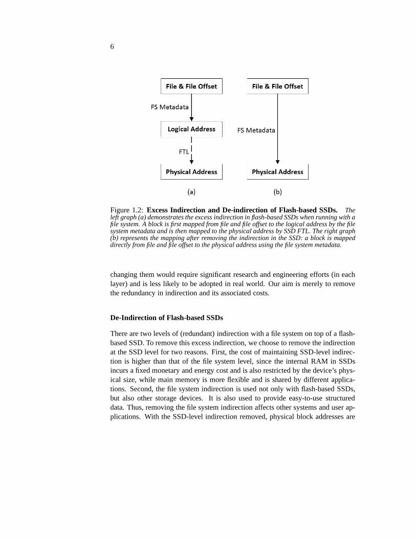
Figure 1.2:Excess Indirection and De-indirection of Flash-based SSDs. Theleft graph (a) demonstrates the excess indirection in flash-based SSDs when running with afile system. A block is first mapped from file and file offset to the logical address by the filesystem metadata and is then mapped to the physical address bySSD FTL. The right graph(b) represents the mapping after removing the indirection in the SSD: a block is mappeddirectly from file and file offset to the physical address using the file system metadata.
changing them would require significant research and engineering efforts (in eachlayer) and is less likely to be adopted in real world. Our aim is merely to removethe redundancy in indirection and its associated costs.
De-Indirection of Flash-based SSDs
There are two levels of (redundant) indirection with a file system on top of a flash-based SSD. To remove this excess indirection, we choose to remove the indirectionat the SSD level for two reasons. First, the cost of maintaining SSD-level indirec-tion is higher than that of the file system level, since the internal RAM in SSDsincurs a fixed monetary and energy cost and is also restrictedby the device’s phys-ical size, while main memory is more flexible and is shared by different applica-tions. Second, the file system indirection is used not only with flash-based SSDs,but also other storage devices. It is also used to provide easy-to-use structureddata. Thus, removing the file system indirection affects other systems and user ap-plications. With the SSD-level indirection removed, physical block addresses are
7
stored directly in file system metadata; file systems use these addresses for readsand overwrites.
We remove the indirection in SSDs without removing or changing their majorfunctionality, such as physical address allocation and wear leveling. An alternativeway to remove indirection is to remove the SSD FTL and manage raw flash memorydirectly with specific file systems [41, 92, 93]. We believe that exposing raw flashmemory to software is dangerous (e.g., a file system can wear out the flash memoryeither by intention or by accident). Vendors are also less likely to ship raw flashwithout any wear guarantees.
To perform de-indirection of flash-based SSDs, our first technique is to re-move the need for SSD-level address mapping with a new interface callednamelesswrites. This interface removes the need for SSDs to create and maintain its indirec-tion mappings. Our second technique is to have the SSD and filesystem both createtheir indirection and operate (largely) unmodified, and to use a tool called “file sys-tem de-virtualizer” to occasionally walk through the file system and remove theSSD-level indirection. We next introduce these techniques.
1.3 De-indirection with Nameless Writes
Our first technique to perform de-indirection for flash-based SSDs is a new inter-face which we termnameless writes[95]. With nameless writes, the indirection inflash-based SSDs is directly removed (i.e., the device never creates mappings forthe data written with nameless writes).
Unlike most writes, which specify both thedata to write as well as aname(usually in the form of a logical address), a nameless write simply passes the datato the device. The device is free to choose any underlying physical block for thedata; after the devicenamesthe block (i.e., decides where to write it), it informsthe file system of its choice. The file system then records the name in its metadatafor future reads and overwrites.
One challenge that we encounter in designing nameless writes is the need forflash-based SSDs to move physical blocks for tasks like wear leveling. When thephysical address of a block is changed, its corresponding file system metadata alsoneeds to be changed so that the proper block can be found by future reads. There-fore, for physical address changes, we use a new interface called migration call-backsfrom the device to inform the file system about the address changes.
Another potential problem with nameless writes is the recursive update prob-lem: if all writes are nameless, then any update to the file system requires a recur-sive set of updates up the file-system tree. To circumvent this problem, we introduce

8
a segmented address space, which consists of a (large) physical address space fornameless writes, and a (small) virtual address space for traditional named writes. Afile system running atop a nameless SSD can keep pointer-based structures in thevirtual space; updates to those structures do not necessitate further updates up thetree, thus breaking the recursion.
Nameless writes offer a great advantage over traditional writes, as they largelyremove the need for indirection. Instead of pretending thatthe device can receivewrites in any frequency to any block, a device that supports nameless writes is freeto assign any physical page to a write when it is written; by returning the true name(i.e., the physical address) of the page to the client above (e.g., the file system),indirection is largely avoided, reducing the monetary costof the SSD, improvingits performance, and simplifying its internal structure.
Nameless writes (largely) remove the costs of indirection without giving awaythe primary responsibility an SSD manufacturer maintains:wear leveling. If anSSD simply exports the physical address space to clients, a simplistic file system orworkload could cause the device to fail rather rapidly, simply by over-writing thesame block repeatedly (whether by design or simply through afile-system bug).With nameless writes, no such failure mode exists. Because the device retainscontrol of naming, it retains control of block placement, and thus can properlyimplement wear leveling to ensure a long device lifetime. Webelieve that anysolution that does not have this property is not viable, as nomanufacturer wouldlike to be so vulnerable to failure.
We demonstrate the benefits of nameless writes by porting theLinux ext3 filesystem to use a nameless SSD. Through extensive analysis on an emulated name-less SSD and comparison with different FTLs, we show the benefits of the newinterface, in both reducing the space costs of indirection and improving random-write performance. Overall, we find that compared to an SSD that uses a hybridFTL (one that maps most SSD area at a coarse granularity and a small area at a finegranularity), a nameless SSD uses a much smaller fraction ofmemory for indirec-tion while improving performance by an order of magnitude for some workloads.
1.4 Hardware Experience with Nameless Writes
To evaluate our nameless writes design, we built and used an SSD emulator. In thepast, most other research on flash-based SSDs also used simulation or emulationfor evaluation [6, 74, 78, 40],
There is little known about real-world implementation trade-offs relevant toSSD design, such as the cost of changing their command interface. Most such

9
knowledge has remained the intellectual property of SSD manufacturers [43, 30,32, 73], who release little about the internal workings of their devices. This situ-ation limits the opportunities for research innovation on new flash interfaces, newOS and file system designs for flash, and new internal management software forSSDs.
Simulators and emulators suffer from two major sources of inaccuracy. First,they are limited by the quality of performance models, whichmay miss importantreal-world effects. Second, simulators and emulation often simplify systems andmay leave out important components, such as the software stack used to access anSSD. For example, our SSD emulator suffers from a few limitations, including amaximum throughput (lowest latency) of emulated device, aswill be described inChapter 3.
Nameless writes require changes to the block interface, flash management al-gorithms within the device, the OS storage stack, and the filesystem. Thus, evalu-ating nameless writes with emulation alone may miss important issues of namelesswrites. Meanwhile, the nameless writes design is an ideal candidate for studyingthe difference between real hardware and simulation or emulation because of thechanges needed by nameless writes at different storage layer. Therefore, we soughtto validate our nameless writes design by implementing it asa hardware prototype.
We prototype nameless writes with the OpenSSD Jasmine SSD hardware plat-form [86]. The OpenSSD evaluation board is composed of commodity SSD parts,including a commercial flash controller, and supports standard storage interfaces(SATA). It allows the firmware to be completely replaced, andtherefore enablesthe introduction of new commands or changes to existing commands in addition tochanges to the FTL algorithms. As a real storage device with performance com-parable to commercial SSDs, it allows us to test new SSD designs with existingfile-system benchmarks and real application workloads.
During prototyping, we faced several challenges not foreseen by our design andevaluation of nameless writes with emulation or in published work on new flashinterfaces. First, we found that passing new commands from the file-system layerthrough the Linux storage stack and into the device firmware raised substantialengineering hurdles. For example, the I/O scheduler must know which commandscan be merged and reordered. Second, we found that returningaddresses with awrite command is difficult with the ATA protocol, since the normal ATA I/O returnpath does not allow any additional bits for an address. Third, upcalls from thedevice to the host file system as required by the migration callbacks turned out tobe challenging, since all ATA commands are sent from the hostto the device.
To solve these problems, we first tried to integrate the nameless writes inter-

10
faces into the SATA interface and implement all nameless writes functionality en-tirely within the firmware running on the OpenSSD board. However, it turned outthat passing data from the device to the host OS through the ATA interface is ex-tremely difficult.
This difficulty led us to a split-FTL design. A minimal FTL on the deviceexports primitive operations, while an FTL within the host OS uses these primi-tives to implement higher-level functionality. This splitdesign simplifies the FTLimplementation and provides a convenient mechanism to workaround hardwarelimitations, such as limited DRAM or fixed-function hardware.
Our evaluation results demonstrate that the nameless writes hardware proto-type using the split-FTL design significantly reduces the memory consumption ascompared to a page-level mapping FTL, while matching the performance of thepage-level mapping FTL, the same conclusion we find with our SSD emulation.Thus, the split-FTL approach may be a useful method of implementing new inter-face designs relying on upcalls from an SSD to the host.
1.5 A File System De-virtualizer
Nameless writes provide a solution to remove the excess indirection in flash-basedSSDs (and the cost of this indirection) by using a new interface between file systemsand flash-based SSDs. Specifically, with nameless writes, the file system sendsonly data and no logical address to the device; the device then allocates a physicaladdress and returns it to the file system for future reads. We demonstrated withboth emulation and real hardware that nameless writes significantly reduce both thespace and the performance cost of SSD virtualization. However, nameless writeshave their own shortcomings.
First, the nameless writes solution requires fundamental changes to the deviceI/O interface. It also requires substantial changes in the device firmware, the filesystem, the OS, and the device interface. Our hardware experience with namelesswrites demonstrates that they are difficult to integrate into existing systems (seeChapter 5) and may need a complete redesign of the storage stack.
Another problem with nameless writes is that all I/Os are de-virtualized at thesame time when they are written. The overhead of nameless writes thus occurs forall writes. However, such overhead caused by de-indirection can be hidden if de-indirection is performed at device idle time and not for all the writes. An emergingtype of storage systems maintain the device indirection layer in software [46]. Insuch case, the indirection mappings do not need to be removedall the time. Usingtechniques like nameless writes to remove indirection mappings for all the data can

11
turn out to be unnecssary and cause more overhead than needed.
To address the problems with nameless writes, we propose theFile SystemDe-Virtualizer (FSDV), a mechanism to dynamically remove the indirection inflash-based SSDs with small changes to existing systems. Thebasic techniqueis simple; FSDV walks through the file system structures and changes file systempointers from logical addresses to physical addresses. Doing so does not requirechanges in normal I/Os. Unlike nameless writes which requires all I/Os to be de-virtualized, the FSDV tool can be invoked dynamically (for example, when the de-vice is idle). We believe that FSDV provides a simple and dynamic way to performde-virtualization and can be easily integrated into existing systems.
One major design decision that we made to achieve the goal of dynamic de-virtualization is the separation of different address spaces and block status withina file system. Initially, the file system allocates logical addresses on top of a vir-tualized device in the traditional way; all blocks are in thelogical address spaceand the device uses an indirection table to map them to thedevice address space.FSDV then walks through and de-virtualizes the file system. Afterwards, the de-virtualized contents are in thephysical address spaceand corresponding mappingsin the device are removed. The file system later allocates andoverwrites data foruser workloads; the device will add new mappings for these data, causing blocks tobe mapped from logical or old physical addresses to current device addresses.
A block thus can be in three states: a mapped logical block, a mapped physicalblock, or a direct physical block. The first two require indirection mapping entries.When the mapping table space for them is large, FSDV can be invoked to movedata from the first two states to the direct state. It can also be invoked periodicallyor when the device is idle. FSDV thus offers a dynamic solution to remove excessvirtualization without any fundamental changes to existing file systems, devices, orI/O interface.
Another design question that we met is related to how we handle the addressmapping changes caused by the device garbage collection andwear leveling oper-ations. During these operations, the device moves flash pages to new locations andthus either changes their old mappings or adds new mappings (if they originallywere direct physical blocks). In order for FSDV to process and remove the map-pings caused by these operations, we choose to associate each block with its inodenumber and record the inode number if the device moves this block and creates amapping for it. Later, when FSDV is invoked, it processes thefiles correspond-ing to these inode numbers and removes the mappings created because of garbagecollection or wear leveling.
We change the write interface to let the file system send the inode number

12
associated with a block when writing it. Though this change is made to a normalI/O interface (something we try to avoid), it only changes the forward direction(from the file system to the device). As will be described in chapter 5, the directionfrom the device to the file system turns out to be the major difficulty when changingthe interface with existing hardware and software stacks. Therefore, we believe thatour change to the write interface for FSDV is a viable one; in the future, we plan toexplore other options to deal with address mapping changes caused by the device.
We implemented FSDV as a user-level tool and modified the ext3file systemand the SSD emulator for it. The FSDV tool can work with both unmounted andmounted file systems. We evaluate the FSDV prototype with macro-benchmarksand show through emulation that FSDV significantly reduces the cost of devicevirtualization with little performance overhead. We also found that by placing mostof the functionality in FSDV, only small changes are needed in the file system, theOS, the device, and the I/O interface.
1.6 Overview
The rest of this dissertation is organized as follows.
• Background: Chapter 2 provides a background on flash memory, flash-based SSDs, file systems, and the ext3 file system.
• Flash-based SSD Emulator:Before delving into our solutions to removeexcess indirection in flash-based SSDs, we first present in Chapter 3 a flash-based SSD emulator that we built for various flash-related research and theresearch work in this dissertation. As far as we know, we are the first to buildand use an SSD emulator for research work; all previous research uses SSDsimulators. We describe the challenges and our solutions tobuild an accurateand flexible SSD emulator.
• De-indirection with Nameless Writes: Our first solution to remove excessindirection in flash-based SSDs is the new interface, nameless writes. Chap-ter 4 discusses the design of the nameless writes interface and the changesneeded in the file system and in the SSD for nameless writes. Namelesswrites largely reduce the indirection memory space cost andperformanceoverhead in SSDs.
Chapter 5 describes our efforts to build nameless writes on real hardware, thechallenges that we did not foresee with emulation, and our solutions to them.

13
• De-indirection with a File System De-Virtualizer: Our second solutionfor de-indirection in flash-based SSDs is the mechanism of a file system de-virtualizer (FSDV). Chapter 6 describes our design of the FSDV mechanism.The FSDV mechanism requires no or few changes to the I/O interface, the OSand file system, and the SSD, yet is able to dynamically reducethe indirectionin flash-based SSDs.
• Related Work: In Chapter 7, we first discuss systems that exhibit excessindirection and other efforts to perform de-indirection. We then present re-search work in flash memory and storage interfaces that are related to thisdissertation.
• Conclusions and Future Work: Chapter 8 concludes this dissertation witha summary of our work, the lessons we have learned, and a discussion offuture work.

14

15
Chapter 2
Background
This chapter provides a background of various aspects that are integral to this dis-sertation. First, since we focus on removing the excess indirection in flash-basedSSDs, we provide a background discussion on flash memory and flash-based SSDs,their internal structures and the softwares that manage them. We then describe thebasics of file systems with a focus on the ext3 file system; we make various changesto ext3 to achieve the goal of de-indirection. Finally, we discuss the block interfacebetween host OSes and block devices and the SATA interface technology whichsupports the block interface.
2.1 Flash-based SSD: An Indirection for Flash Memory
We now provide some background information on the relevant aspects of NANDflash technology. Specifically, we discuss their internal structure, NAND-flash-based SSDs, and the software that manages them.
2.1.1 Flash Memory and Flash-based SSDs
NAND Flash Memory Internals
Figure 2.1 illustrates the internals of a NAND flash memory cell. A NAND flashmemory cell (representing a bit) contains a floating gate (FG) MOSFET [80, 20].Each gate can store one (SLC) or more (MLC/TLC) bits of information. The FGis insulated from the substrate by the tunnel oxide. After a charge is forced tothe FG, it cannot move from there without an external force. Excess electronscan be brought to (program) or removed from (erase) a cell, usually performedby the Fowler-Nordheim (FN) tunneling. After a page is written (programmed),

16
Figure 2.1:Internals of A Flash Memory Cell. This graph illustrates what a NANDflash memory cell looks like. There are two transistor gates (control and floating), whichare insulated by thin layers of oxide layer. The number of electrons in the insulated floatinggate determines the bit or bits (SLC or MLC/TLC) of the cell. To change the amount ofelectrons in the floating gate, voltages between the controlgate and source or drain areapplied.
it needs to be erased before subsequent writes. Depending onthe amount of thecharges stored in the FG, a cell can be in two or more logical states. A cell encodesinformation via voltage levels; thus, being able to distinguish between high and lowvoltage is necessary to differentiate a 1 from a 0 (for SLC; more voltage levels arerequired for MLC and TLC) [38]. MLC and TLC are thus denser than SLC buthave performance and reliability costs.
NAND flash reads and writes are performed at the granularity of flash page,which is typically 2 KB, 4 KB, or 8 KB. Before writing to a flash page, a largersizeerase block(usually between 64 KB to 4 MB) must be erased, which sets allthe bits in the block to 1. Writes (which change some of the 1s to 0s) can thenbe performed to all the flash pages in the newly-erased block.In contrast to thisintricate and expensive procedure, reads are relatively straightforward and can bereadily performed in page-sized units.
Writing is thus a noticeably more expensive process than reading. For example,Gruppet al. report typical random read latencies of 12µs (microseconds), write(program) latencies of 200µs, and erase times of roughly 1500µs [37]. Thus, inthe worst case, both an erase and a program are required for a write, and a write willtake more than 100× longer than a read (141× in the example numbers above).

17
Figure 2.2:Internals of Flash-based SSD.We show the internals of a typical flash-based SSD, which contains a controller, a RAM space, and a setof flash chips.
An additional problem with flash is its endurance [90]. Each P/E operationcauses some damage to the oxide by passing a current through the oxide and plac-ing a high electric field across the oxide, which in turn results in a degradationin threshold voltage. Over time it becomes increasingly difficult to differentiate a1 from a 0 [1, 13]. Thus, each flash erase block has a lifetime, which gives thenumber of P/E cycles that the device should be able to performbefore it fails. Typ-ical values reported by manufacturers are 100,000 cycles for NAND SLC flash and10,000 for MLC, though some devices begin to fail earlier than expected [37, 70].

18
Flash-based SSDs
A Solid-state drive(SSD) is a storage device that uses (usually non-volatile) mem-ory for data storage. Most modern SSDs use flash memory as their storage medium;early SSDs also use RAM or other similar technology. No hard disks or any devicewith mechanical moving parts are used in SSDs. Compared to traditional hard diskdrives (HDDs), SSDs have better performance (especially random performance)and are more shock resistant and quieter. Flash-based SSDs are also cheaper andconsume less energy than RAM. Thus, they have gained an increasing foothold inboth consumer and enterprise market.
Flash-based SSDs usually contain a set of NAND flash memory chips, an in-ternal processor that runs SSD-management firmware, and a small SRAM and/orDRAM. The processor runs the flash management firmware. The internal RAM isused to store the SSD indirection mapping table and sometimes for a read cache ora write buffer, too. More details about the SSD firmware and mapping tables willbe discussed in the next section.
The flash memory chips are used to store data persistently. Flash memory areoften organized first into flash pages, then into flash erase blocks, then into planes,dies, and finally into flash chips [6]. An out of band (OOB) area is usually associ-ated with each flash page, storing error correction code (ECC) and other per-pageinformation. To improve performance (i.e., bandwidth), the flash memory chips areoften organized in a way so that multiple flash planes can be accessed in parallel [6].Figure 2.2 gives an illustration of flash-based SSD internalorganization.
Modern NAND flash-based SSDs appear to a host system as a storage devicethat can be written to or read from in fixed-size chunks, much like modern HDDs.SSDs usually provide a traditional block interface throughSATA. In recent years,high-end SSDs start to use the PCIe bus or RPC-like interfaces for better perfor-mance and more flexibility [31, 65, 72].
2.1.2 Flash Memory Management Software
For both performance and reliability reasons and to providethe traditional blockI/O interface, most flash devices virtualize their physicalresources using aFlashTranslation Layer(FTL) that manages the underlying flash memory and exportsthe desired disk-like block interface. FTLs serve two important roles in flash-basedSSDs; the first role is to improve performance, by reducing the number of erasesrequired per write. The second role is to increase the lifetime of the device throughwear leveling; by spreading erase load across the blocks of the device, thefailureof any one block can be postponed (although not indefinitely).

19
Figure 2.3: Illustration of a Hybrid FTL before a Merge Operation In thisexample, there are two log blocks and three data blocks in theSSD with a hybrid FTL, eachcontaining four 4 KB flash pages. The data blocks contain 12 pages in total; the SSD thusexposes an effective adddress space of 48 KB (12× 4 KB) to the OS. The log blocks are fulland a merge operation is triggered. First, to get a free block, the third data block (LBA 8to 11) is erased, since all its pages are invalid. The FTL thenmerges logical pages LBA0 to 3 from their current valid location (two log blocks and one data block) to the erasedfree data block. After the merge operation, the old data block (leftmost data block) can beerased.
Both of these roles are accomplished through the simple technique of indirec-tion. Specifically, the FTL maps logical addresses (as seen by the host system) tophysical blocks (and hence the name) [42]. Higher-end FTLs never overwrite datain place [35, 40, 59, 60, 62]; rather, they maintain a set of “active” blocks that have

20
Figure 2.4: Illustration of a Hybrid FTL after a Merge Operation This figuregives an illustration of a typical hybrid FTL after a merge operation. After the mergeoperation, the old data block (leftmost data block) has beenerased and becomes a freeblock.
recently been erased and write all incoming data (in page-sized chunks) to theseblocks, in a style reminiscent of log-structured file systems [77]. Some blocks thusbecome “dead” over time and can be garbage collected; explicit cleaning can com-pact scattered live data and thus free blocks for future usage.
The hybrid FTLs use a coarser granularity of address mapping(usually per64 KB to 4 MB flash erase block) for most of the flash memory region (e.g., 80% ofthe total device space) and a finer granularity mapping (usually per 2-KB, 4-KB, or8-KB flash page) for active data [59, 60]. Therefore, the hybrid approaches reducemapping table space for a 1 TB SSD to 435 MB, as apposed to 2 GB mapping tablespace if addresses are mapped all at 4-KB page granularity.
The page-mapped area used for active data is usually called the log block area;the block-mapped area used to store data at their final location is called thedatablock area. The pages in a log block can have any arbitrary logical addresses. Log-

21
structured allocation is often used to write new data to the log blocks. The rest ofthe device is a data block area used to store data blocks at their final locations. Thepages in a data block have to belong to the same erase block (e.g., 64 4-KB pagesin a 256 KB consecutive logical block address range). The hybrid mapping FTLmaintains page-level mappings for the log block area and block-level mappings forthe data block area.
When the log block area is full, costly merge operations are invoked. A mergeoperation is performed to free a data block bymergingall the valid pages belongingto this data block to a new free block; afterwards the old datablock can be erased.Figures 2.3 and 2.4 illustrate the status of a hybrid SSD before and after the mergeoperation of a data block (which contains LBAs 0 to 3). After this merge operation,two pages in two log blocks are invalidated. To free a log block, all the pagesin it need to be merged to data blocks. Thus, such merge operations are costly,especially for random writes, since the pages in a log block can belong to differentdata blocks. Therefore, some hybrid FTLs maintain a sequential log block forsequential write streams [60]. When the sequential log block is full, it is simplyswitched with its corresponding data block.
Hybrid FTLs also perform garbage collection for data blocks, when the totalamount of free data blocks are low. The merge operations needed to free a datablock are the same as described above. To reduce the cost of such merging, avictim data block is often chosen as the data block that has the least amount ofvalid data.
FTLs also performwear leveling, a technique to extend the life of SSDs byspreading erases evenly across all blocks. If a block contains hot data, it will bewritten to and erased more often and approaches its lifetimelimit faster than blockswith cold data. In such case, a wear leveling operation can simply swap the blockcontaining hot data with a block containing cold data [6]. After this operation, thecorresponding mapping table is updated to reflect the new physical addresses of theswapped data–another reason for indirection in flash-basedSSDs. In order for theFTL to know the erase cycles and temperature of a block, it needs to keep certainbookkeeping. Most FTLs maintain an erase count with each block. To measurethe temperature of a block, a simple technique is to record the time when any ofthe pages in a block is last accessed. A more accurate method is to record thetemperature of all the pages in a block; this method requiresmore space with eachflash page to store the temperature information.
In summary, flash-based SSDs are a type of virtualized storage device, whichuses indirection to hide its internal structures and operations and to provide a tradi-tional block I/O interface.

22
2.2 File System: An Indirection for Data Management
File systems are software systems that organize data and provide an easy-to-useabstract form for storage devices [10].
Most file systems view a storage device as a contiguouslogical address spaceand often divide it into fix-sized blocks (e.g. 4 KB). Data blocks are first structuredinto files; files are then organized into a hierarchy of directories. To manage datawith such structures, file systems keep their own metadata, such as block pointers toidentify blocks belonging to a file, file size, access rights,and other file properties.
File systems serve as an indirection layer and map data from file and file offsetsto logical addresses. A data block is read or written with itsfile offset. File systemsallocate logical block addresses for new data writes. Bitmaps are often used totrack the allocation status of the device; a bit represents alogical block address andis set when the block is allocated. Accordingly, file systemsperform de-allocationfor deletes and truncates, and unset the bit in the bitmap. File systems also performallocation and de-allocation for file system metadata in a similar way as data alloca-tion and de-allocation. For reads and (in-place) overwrites, file systems look up thefile system metadata and locate their logical block addresses. Certain file systemmetadata (e.g., superblock, root directory block) have fixed locations so that theycan always be found without any look-ups.
2.2.1 The Ext3 File System
We now give a brief description of a concrete example of file system, theext3file system. Ext3 is a classic file system that is commonly usedin many Linuxdistributions [10]; thus, we choose to use ext3 in all our works in this dissertation.
A file in ext3 is identified by the structure ofinodewith a uniqueinode number.Ext3 uses a tree structure of pointers to organize data in a file. The inode can beviewed as the tree root, it points to a small number (e.g., twelve) of data blocks.When the file is bigger than this amount of data, the inode alsopoints to anindirectblock, which in turn points to a set of data blocks. If the file is evenbigger,doubleor triple indirect blocks are used which points to one or two levels of indirect blocksand eventually to data blocks.
The address space in ext3 is split into block groups, each containing equal sizeof blocks. Each block group contains a block group descriptor, a data block bitmap,an inode bitmap, an inode table, indirect blocks, and data blocks. Ext3 uses thebitmaps for data and inode allocation and de-allocation. Directories are also storedas files. Each directory contains the information (e.g., file/subdirectory name, inodenumber) of the files or the subdirectory in the directory. Figure 2.5 illustrates the
23
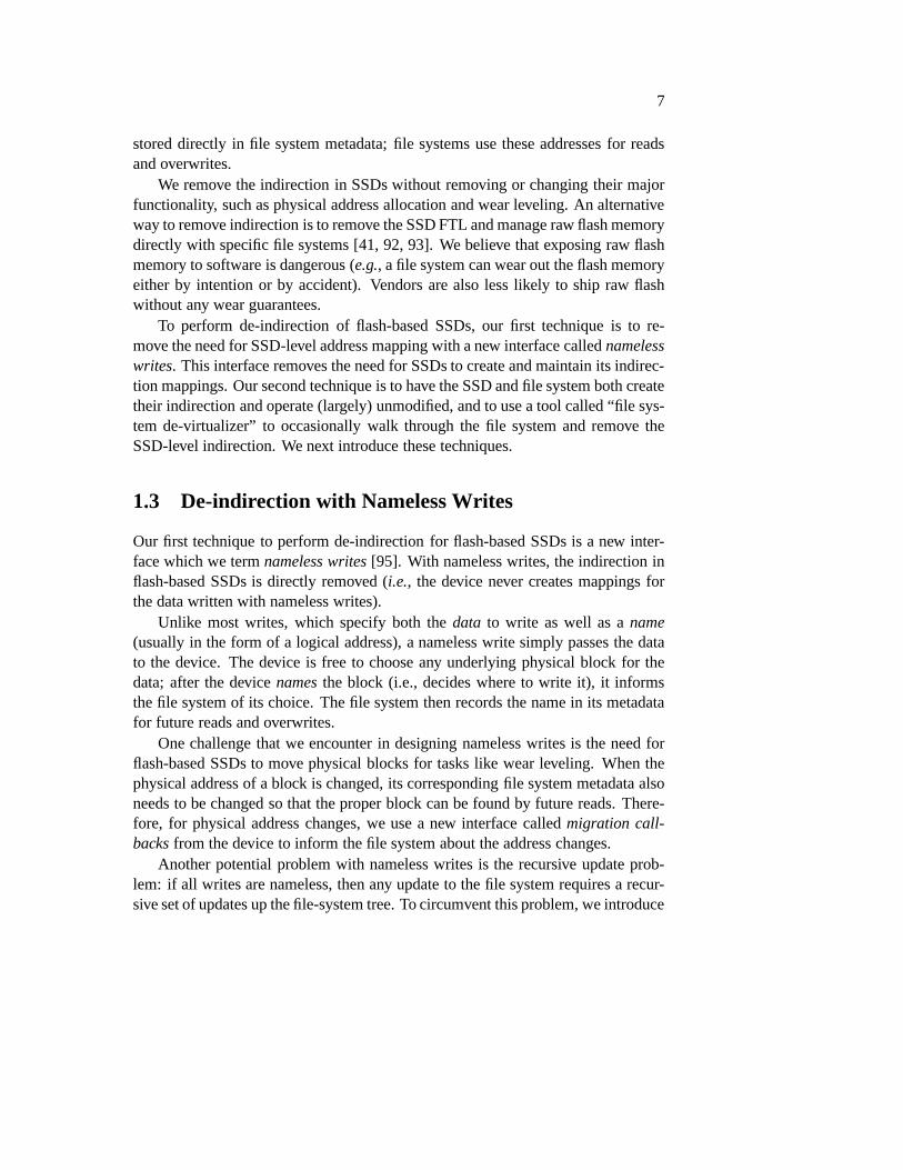
Figure 2.5:An Illustration of the Ext3 File System. This figure shows a simpleillustration of the ext3 file system data structures and on-disk layouts. In the top part ofthe graph, we show the directory and file tree. This example file has one level of indirectblocks and is pointed to directly by the root directory. The bottom part of the graph showsthe layout of the ext3 block group.
directory, file, and block group structures of ext3.
Ext3 also provides reliability and fast recovery through the technique of jour-naling. Ext3 has three journaling modes: journal mode whereboth metadata anddata are written to the journal, ordered mode where only metadata is journaled butdata are guaranteed to be written to disk before metadata in the journal are written,and writeback mode where only metadata is journaled and there is no ordering ofmetadata and data writes. We choose the ordered mode in the work in this disser-tation, since it is a widely used journaling mode.
In summary, file systems such as ext3 organize data into file and directory struc-tures and provide consistency and reliability through the technique of indirection(in the form of file system metadata). File system metadata serve as the means offile system indirection. However, there are certain space and performance cost to

24
maintain this indirection. Combined with the indirection in flash-based SSDs, wesee excess indirection with a file system running on top of an SSD.
2.3 Block Interface and SATA
Most flash-based SSDs work as block devices and connect to theOS hosts usingtheblock interface. The block interface is also the most common interface for otherstorage devices such as hard disks. Thus, in this section we give a brief backgrounddescription of the block interface and a particular hardware interface that supportsthe block interface: the SATA interface.
The block interface transfers data in the form of fix-sized blocks between ablock device and the host OS. All reads and writes use the sameblock size. Theblock interface exposes a single address space (the logicaladdress space) and sup-ports sequential and random access to any block addresses. Ablock I/O is sentfrom the OS to the device with its block address, a buffer to store the data to bewritten or read, and the direction of the I/O (i.e., read or write). The OS expects areturn from the block interface with the status and error of the I/O and the data tobe read.
SATA Interface
The SATA (Serial Advance Technology Attachment) interfaceis a common inter-face that works with block devices [85]. It is a replacement for the older PATA(Parallel ATA) interface and uses serial cable for host connection. There are threegenerations of SATA: SATA 1.0 whose communication rate is 1.5 Gbit/s, SATA 2.0(3 Gbit/s), and SATA 3.0 (6 Gbit/s).
The SATA interface technology uses layering and contains several layers onboth the transmit (host OS) and the receive (device) sides asshown in Figure 2.6.The application and command layers receive commands from the host or the deviceand then set up and issue commands to the lower layers. The transport layer is re-sponsible for the management of Frame Information Structures (FISes). It formatsand passes FISes to the link layer. The link layer converts data into frames and pro-vides frame flow control. Finally, the physical layer performs the actual physicaltransmission.
ATA commands can be classified into I/O commands and non-datacommands.Within I/O commands, there are both PIO (Programmed IO) and DMA (DirectMemory Access) read and write commands. Both PIO and DMA I/O commandshave similar forms. The input fields (from host to device) include the command
25
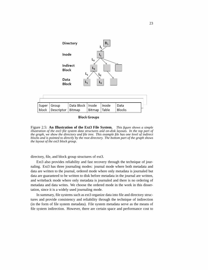
Figure 2.6:Layered Structure of SATA. This graph demonstrates the layers in theSATA technology. On both the host and the device side, there are five layers: application,command, transport, link, and physical layers. The physical layer performs the actualphysical communication.
type, the logical block address and the size of the I/O request, and the device. Thereturn fields (from device to host) include the device, status bits, error bits, andpossibly the error LBA. The status bits represent the statusof the device (e.g., ifbusy). For a normal I/O command return, only the status bits are set. The error bitsencode the type of error the command encounters. If there is an error (i.e., error bitsare set), then the first logical block address where the erroroccurs is also returnedto the host.
The non-data commands in ATA are used for various purposes, such as device

26
configurations, device reset, and device cache flush. The input fields of the non-data commands may include features, LBA, sector count, device, and command.The output fields may include status, error, LBA, and size.
In summary, the block interface is a simple and convenient interface for readingand writing in fixed block size to storage devices. The hardware interface thatsupports block I/Os is more complex; the SATA interface technology uses multiplelayers on both host and device sides. The SATA interface alsohas a strict set ofcommand protocols and is thus difficult to change.
2.4 Summary
In this chapter, we give different pieces of background for the rest of the disserta-tion.
We first discuss the technology of flash memory and flash-basedSSDs, theirinternals and the software that controls and manages them. Such software layer usesindirection to hide the internal structures and operationsof flash-based SSDs. Withthis indirection, a block is mapped from its logical addressto its physical address.In this process, the SSD software performs allocation in thephysical address space.
We then give a brief overview of file systems and a particular example filesystem, the Linux ext3 file system. The file system is another level of indirectionto map a block from its file and file offset to its logical address. The file systemperforms allocation in the logical address space. Thus, we see redundant levels ofaddress allocation and indirection mappings.
Finally, we describe the interface between the file system and the typical flash-based SSDs: the block interface and the SATA technology.

27
Chapter 3
A Flash-based SSD Emulator
Because of the increasing prevalence of flash-based SSDs andmany unsolved prob-lems of them, a large body of research work has been conductedin the recent years.Most SSD research relies on simulation [6, 40, 74].
Simulation is a common technique to model the behavior of a system. A storagedevice simulator often takes an I/O event and its arrival time as its input, calculatesthe time the I/O is supposed to spent with the device, and returns this time as out-put [15]. A model of a certain device is usually used to calculate the I/O requesttime. Simulation provides a convenient way to evaluate new design and is relativelyeasy to implement and debug.
Over the past years, a few SSD simulators have been built and published. TheMicrosoft Research’s SSD simulator is one of the first publicSSD simulators andoperates as an extension to the DiskSim framework [6]. The PSU FlashSim isanother SSD simulator that operates with DiskSim and include several page-level,block-level, and hybrid FTLs [53]. Leeet al. built a stand-alone SSD simulatorwith a simple FTL [56].
These SSD simulators have been used extensively in many SSD research works [6,40, 22, 96]. However, simulation has its own limitations. First, simulators cannotbe used directly to evaluate real workloads on real systems.Real workloads andbenchmarks have to be converted specifically for a simulator. In this process oftransitioning, different aspects of the workloads and the system can be lost or al-tered. Second, with simulation, many real system properties and interfaces aresimplified. For example, it is difficult to model multithreading behavior with asimulator. Thus, simulation alone is not enough for all evaluation situations andrequirements.
Emulation provides another way to evaluate a storage device. A storage device

28
emulator tries to mimic the behavior of a real device. For example, it returns an I/Orequest at the same wall clock time as what the real device would return. A deviceemulator also uses a real interface to the host OS. Real workloads and benchmarkscan thus run directly on an emulator. Device emulation is thus especially useful toevaluate the interaction of host OS and the device.
Accurate emulation is difficult because of different real system effects, con-straints, and non-deterministic nature [36]. The major challenge in implementingan SSD emulator is to accurately model the SSD performance, which is much closerto CPU and RAM than traditional hard disks.
We implemented an SSD emulator and use it throughout different parts of thisdissertation. The overall goal of our emulation effort is tobe able to evaluate newdesigns (e.g., SSD de-indirection) using important metrics with common SSD hard-ware configurations. We leverage several techniques to reduce various computa-tional overhead of the emulator.
Because of the difficulty in building an always-accurate emulator and the lim-ited knowledge of the internals of real SSDs, we do not aim to build an always-accurate emulator that works for all metrics and all SSD configurations. The goalof our emulator is not to model one particular SSD perfectly but to provide in-sight into the fundamental properties and problems of different types of SSD FTLs.For example, our emulator can accurately emulate write performance for commontypes of SSDs, but not read performance; writes are the bottleneck to most SSDsand the focus of this dissertation.
As a result, we built a flexible and generally accurate SSD emulator, whichworks as a block device with the Linux operating system. Our evaluation resultsshow that our SSD emulator has low computational overhead and is accurate forimportant metrics and common types of SSDs. As far as we know,we are the firstto implement an SSD emulator and use it to evaluate new designs.
The rest of this chapter is organized as follows. We first discuss our design andimplementation of our SSD emulator in Section 3.1. We then present the evaluationresults of the emulator in Section 3.2. Finally, we discuss the limitations of our SSDemulator in Section 3.3 and summarize this chapter in Section 3.4.
3.1 Implementation
We built a flash-based SSD emulator below the Linux block layer; it processesblock I/O requests sent from the file system. The SSD emulatorhas the standardblock interface to the host OS and can be used as a traditionalblock device. Inter-nally, we implemented the emulator as a Linux pseudo block device.

29
Our goal is to have a generally accurate and flexible SSD emulator so thatdifferent SSD and host system designs can be evaluated with real workloads andbenchmarks. Since the latency and throughput of modern flash-based SSDs is muchcloser to those of RAM and CPU than hard disks, the main challenge to build anSSD emulator is to accurately emulate the performance of flash-based SSDs andminimize the computational and other overhead of the emulator. It is especiallydifficult to emulate the parallelism in a multi-plane SSD. For example, if a singleI/O request takes 100µs, then parallel 10 requests to 10 SSD planes will have theeffect of finishing 10 requests in 100µs. In the former case (single request), theemulator only needs to finish all its computation and other processing of a requestwithin 100µs, while in the later case, the emulator needs to finish 10 requests in thesame amount of time. Thus, reducing the computational overhead of the emulatoris important.
We now describe the design and implementation of our SSD emulator and oursolution to the challenges discussed above.
3.1.1 Mechanism
We use three main techniques to build an efficient and accurate emulator. First,we store all data in main memory, including file system metadata and data, FTLaddress mapping table, and other data structures used by theemulator. Second, weseparate the data storage and the device modeling operations to two threads. Third,we avoid CPU time as much as possible at the probable cost of memory overhead.
Our original implementation (Design 1) used a single thread to perform alltasks, including storing or reading data from memory and calculate request re-sponse time by modeling the SSD behavior. Doing so made the total time spentby the emulator for a request higher than the request response time. Therefore, weseparate the emulator into two parts in our next design (Design 2); each part usesa single thread. The major thread is a thread passed from the kernel with a blockI/O request. It first makes a copy of each request and places the copy on a requestqueue. It then performs data storage for the request. We callthis thread the datastorage thread. We use another thread that takes request from the request queue,models SSD behavior, and calculates the response time of therequest.
The data storage thread is responsible for storing and retrieving data to or frommemory. Initially with Design 2, we implemented the data storage thread in a waythat for each write, it allocates a memory space, copies the data to be written at theallocated space, and keeps a mapping in a hash table. This implementation turnedout to be too costly in computational time. Instead inDesign 3(our final design),we pre-allocate all the memory space for the emulated deviceand associate each

30
Figure 3.1:Design of the SSD Emulator. This figure describes the basic architectureof the SSD emulator, which contains two threads, the data store thread and the SSD model-ing thread. When an I/O request is received from the file system, the main thread makes acopy of it and passes both copies to the two threads to performmemory store/retrieval andSSD simulation. When both threads finish their processing, the request is returned to thefile system.
flash page in the emulated SSD statically with a memory slot (through an arraytable). Reading and writing thus simply involve an array look-up and memorycopy. In this way, no memory allocation or hash table look-upis necessary for eachI/O request. Figure 3.1 illustrates the final design of our SSD emulator.
The SSD modeling thread models SSD behavior and maintains a FIFO queueof I/O requests that are passed from the main thread. For eachI/O request, its logi-cal block address, its direction, and its arrival time are passed to an SSD simulator.The SSD simulator simulates SSD behavior with a certain FTL and calculates theresponse time of the request. The SSD model is a separate component and can be

31
replaced by other models. We implemented the SSD simulator based on the PSUobjected-oriented SSD simulator codebase [11]. The PSU SSDcodebase containsthe basic data structures and function skeletons but no implementation of FTLs, ad-dress mapping, garbage collection, wear leveling, or I/O parallelism and queueing;we implemented these functionalities. We will discuss moredetails about our SSDmodel and its FTLs in the next section.
To accurately emulate the response of an I/O request, we usehrtimer, a high-resolution and high-precision Linux kernel timer, to set the time the SSD is sup-posed to finish the I/O request. When the SSD model returns theresponse time, ifit is larger than the current time, then we set the hrtimer to use this response time.Otherwise, the hrtimer uses the current time (i.e., it expires immediately). The lat-ter case happens when the computation time of the SSD model islarger than the(modeled) latency of an I/O request; in this case, the emulator will not be able toaccurately emulate the performance of the modeled SSD. Therefore, it is importantto minimize the computation in the SSD model when implementing the SSD FTLs.
An I/O request is considered finished when both the data storage thread and themodeling thread have finished their processing of the I/O. The data storage threadis considered finished with its processing when it has storedor read the I/O datato or from memory. The modeling thread is considered finishedwhen the timerexpires. Both threads can return the I/O request to the host,when the other threadand itself have both finished their processing. We maintain an identifier with eachI/O to indicate if a thread has finished processing it.
3.1.2 SSD Model
We now discuss our implementation of the SSD simulator and how we model SSDhardware structures and software FTLs. Figure 3.2 illustrates the architecture ofthe modeled SSD.
We model the SSD internal architecture in the following way.The SSD containsa certain number of packages (flash chips); each package contains a set of dies; eachdie has a set of planes. A plane is the unit for I/O parallelism. A plane contains aset of flash erase blocks, which are the unit of the erase operation. An erase blockcontains a set of flash pages, which are the units of reads and writes. There isalso an OOB area with each flash page, which is used to store per-page metadata,such as the logical block address of the page and the page valid bit. The logicalblock address is used to construct the address mapping tableduring SSD start upand recovery. The valid bit is used during garbage collection and wear leveling. Areal SSD also usually stores EEC bits in the OOB area; we do notmodel the errorcorrecting behavior of the SSD. We also store certain information with each erase
32
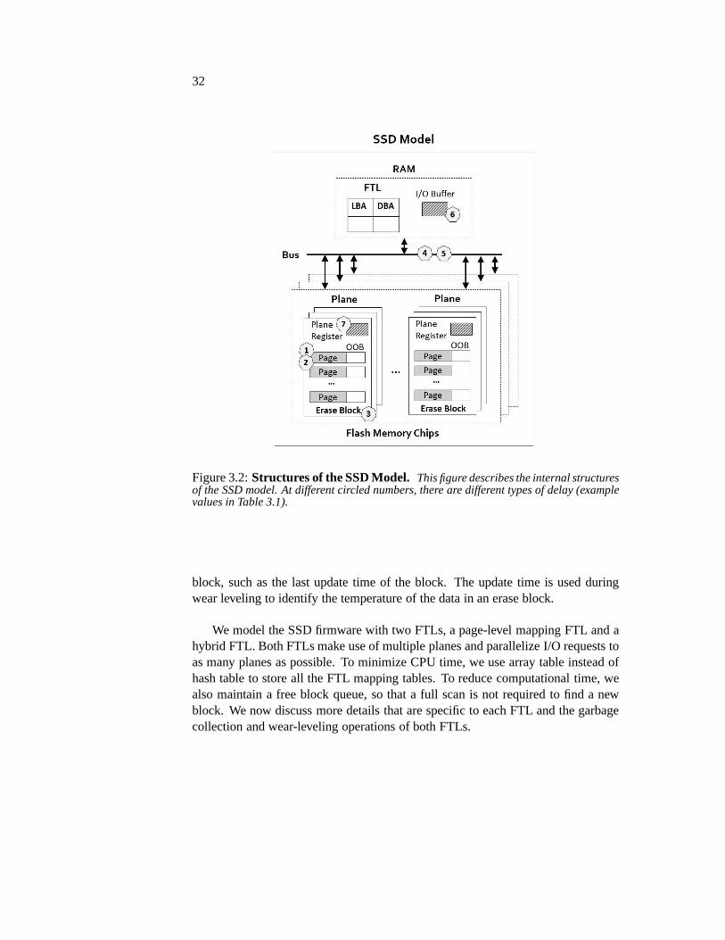
Figure 3.2:Structures of the SSD Model. This figure describes the internal structuresof the SSD model. At different circled numbers, there are different types of delay (examplevalues in Table 3.1).
block, such as the last update time of the block. The update time is used duringwear leveling to identify the temperature of the data in an erase block.
We model the SSD firmware with two FTLs, a page-level mapping FTL and ahybrid FTL. Both FTLs make use of multiple planes and parallelize I/O requests toas many planes as possible. To minimize CPU time, we use arraytable instead ofhash table to store all the FTL mapping tables. To reduce computational time, wealso maintain a free block queue, so that a full scan is not required to find a newblock. We now discuss more details that are specific to each FTL and the garbagecollection and wear-leveling operations of both FTLs.

33
Page-level FTL
The page-level mapping FTL keeps a mapping for each data pagebetween its logi-cal and physical address. For writes, the page-level mapping FTL performs alloca-tion in a log-structured fashion. The FTL maintains an active block in each planeand appends new writes to the next free page in the block. The FTL also paral-lelizes writes in round-robin order across all the planes. For reads, the page-levelmapping FTL simply looks up its mapping table and finds its physical address; itthen performs the read from this physical address.
Hybrid FTL
We implemented a hybrid mapping FTL similar to FAST [60], which uses alogblock areafor active data and adata block areato store all the data. One sequentiallog block is dedicated for sequential write streams. All theother log blocks areused for random writes. The rest of the device is a data block area used to storedata blocks at their final locations. The pages in a data blockhave to belong tothe same erase block (e.g., 64 4 KB pages in a 256 KB consecutive logical blockaddress range). The pages in a random-write log block can have any arbitrarylogical addresses. We choose to use log-structured allocation to write random datato the log blocks. The hybrid mapping FTL maintains page-level mappings for thelog block area and block-level mappings for the data block area.
Garbage Collection and Wear Leveling
We implemented a simple garbage collection algorithm and a simple wear-levelingalgorithm with both the page-level mapping and the hybrid mapping FTLs.
The garbage collection operation is triggered when the number of free blocksin a plane is low. The garbage collector uses a greedy method and recycles blockswith the least live data. During garbage collection, blockswith all invalid pages arefirst selected for recycling. The garbage collector simply erases them. The blockwith the greatest number of invalid pages is then selected. The valid pages in theseblocks are written out into a new block. For the page-level mapping FTL, the validpages are simply written into any free space on any plane (we choose to parallelizethese writes to different planes). For the hybrid mapping FTL, to garbage collect adata block, a merge operation is triggered; the valid pages are either copied fromthe old data block or current log blocks into a new free block.
We implemented a wear-leveling algorithm similar to a previous algorithm [3].The wear-leveling algorithm is triggered when the overall wear of the SSD is high.The SSD considers both block wear and data temperature during the wear leveling

34
operation. A block whose amount of remaining erase cycles isless than a certainpercentage of the average remaining erase cycles of the blocks in the SSD is consid-ered for wear leveling. The SSD then selects the block with the coldest data (oldestupdate time) and swaps its content with the worm block; the corresponding addressmapping entries are also updated accordingly. Notice that because of the need inthe wear-leveling algorithm, the SSD also keeps track of thedata temperature ineach block and stores it with the block.
3.2 Evaluation
In this section, we present our evaluation results of our SSDemulator. We beginour evaluation by answering the questions of how accurate the emulator is andwhat kind of SSDs the emulator is capable of modeling. Our major goal of theemulator is to have low computational overhead so that it canaccurately emulatecommon types of SSDs with important workloads. After findingout the accuracyand capability of our emulation, we delve into the study of more detailed aspectsof the SSD and different FTLs. All experiments are performedon a 2.5 GHz IntelQuad Core CPU with 8 GB memory.
The followings are the specific questions we set to answer.
• What is the computational overhead of the emulator?
• How accurate does the emulator need to be to model an SSD for a partic-ular metric? Can the emulator model common type of SSDs for importantmetrics?
• What is the effect of multiple parallel planes on the performance of an SSD?
• How does the page-level mapping FTL compare to the hybrid mapping one?
• What is the performance bottleneck of the hybrid mapping FTLand why?
Table 3.1 describes the configurations we used in our evaluation. There are dif-ferent kinds of latency associated with various SSD internal structures as shown inFigure 3.2. We use two types of flash memory; SSD1 emulates an older generationof flash memory and SSD2 emulates a newer generation.
3.2.1 Emulation Overhead
We first evaluate the computational overhead of our SSD emulator. The compu-tational overhead limits the type of SSDs the emulator can model accurately; if

35
Configuration SSD1 SSD2SSD Size 4 GB 4 GBPage Size 4 KB 4 KBBlock Size 256 KB 256 KBNumber of Planes∗ 10 10Hybrid Log Block Area∗ 5% 5%Page Read Latency 25µs 65µsPage Write Latency 200µs 85µsBlock Erase Latency 1500µs 1000µsBus Control Delay 2µs 2µsBus Data Delay 10µs 10µsRAM Read/Write Delay 1µs 1µsPlane Register Read/Write Delay 1µs 1µs
Table 3.1: SSD Emulator Configurations. ∗Number of planes and amount of hy-brid log block area use the values in the table as default value but may vary for certainexperiments.
the I/O request time of an SSD is faster than the computation time taken by theemulator, then we cannot model this SSD accurately. Thus, our goal is to have angenerally low computational overhead. However, because ofthe non-deterministicnature of real-time emulation, we allow small amount of outliers.
To evaluate the computational overhead of the emulator, we first study the totaltime spent in the emulator for an I/O requestTE without including the SSD mod-eled request timeTR (i.e., TR = 0). Figure 3.3 plots the cumulative distributionof the total emulation time of synchronous sequential and random writes with thepage-level mapping and the hybrid mapping FTLs. We use the cumulative dis-tribution, since our goal of the emulator is to have an overall low computationaloverhead but allow occasional outliers with higher overhead; the cumulative distri-bution serves to measure if we meet this goal.
Overall, we find that the computational overhead of our emulator is low; themajority of the requests haveTE from 25 to 30µs for both sequential and randomworkloads and for both FTLs. Comparing different workloadsand FTLs, we findthat random writes with the hybrid mapping FTL has higher emulation time than allthe others. There is also a long tail, indicating a small number of outliers that haveextremely high computational overhead (e.g., 1000µs). We suspect that the highcomputational overhead and outliers are due to the complex operations of randomwrites (e.g., merge and garbage collection) with the hybrid mapping FTL.
To further study the emulator overhead and understand wherethe bottleneck is,

36
Emulation Time (usec)10 100 1000
Cum
ulat
ive
Dis
trib
utio
n (%
)
0
20
40
60
80
100
Page_seqPage_randHybrid_seqHybrid_rand
25
Figure 3.3:CDF of the Emulation Time. We perform sustained synchronous 4 KBsequential and random writes with the page-level mapping and the hybrid mapping FTLsand plot the cumulative distribution of the time spent at theemulator (TE). The SSD modelthread does all its modeling computation but always return azero modeled request time(TR = 0).
Data Store Time (usec)0 5 10 15 20 25 30
Cum
ulat
ive
Dis
trib
utio
n (%
)
0
20
40
60
80
100
Figure 3.4: CDF of Data Store Time. This figure plots the cumulative density ofthe time spent at the data store thread using 4 KB sequential writes with the page-levelmapping FTL. The results for the hybrid mapping FTL and for random writes are similarto this graph.
we separately monitor the computational and memory store time taken by the twothreads in the emulator to process each I/O request (TS andTM ). The time takenby the data storage thread includes the time to store or read data from memory andother computational time of the thread. The time taken by theSSD modeling threadincludes all the computational time taken by it but not the actual modeled responsetime of the I/O request (TR = 0).
Figure?? plots the cumulative distributions of the time taken by the data storethread. The figure plots the distribution of synchronous sequential writes using thepage-level mapping FTL, but the other workloads and FTL all have similar distri-

37
SSD Model Time (usec)10 100 1000
Cum
ulat
ive
Dis
trib
utio
n (%
)
0
20
40
60
80
100
Page_seqPage_randHybrid_seqHybrid_rand
Figure 3.5:CDF of time spent by the SSD modeling thread for each I/O request.We perform sustained synchronous 4 KB sequential and randomwrites with the page-levelmapping and the hybrid mapping FTLs. This figure presents thecumulative density of thecomputational spent at the SSD modeling thread. The solid line represents the SSD modelwith the page-level mapping FTL and the dotted line represents the hybrid mapping FTL.
bution; the data store thread is not affected by the SSD modelor type of workloads(as long as the block size in the workloads is the same). We findthat the memorystore time has a median of 12µs and is lower than the total emulation time. Wealso find that the time taken by the data store thread has a small variance, indicatingthat memory store is a stable operation that is not affected by workloads or types ofFTLs.
Figure 3.5 plots the cumulative distributions of the time taken by the SSD mod-eling thread with sequential and random writes and both the page-level mappingand the hybrid mapping FTLs. We find that the SSD model thread takes a median of27 to 31µs for the page-level mapping FTL and 29 to 35µs for the hybrid mappingFTL. The SSD modeling time is similar to the total emulation time and is alwaysbigger than the data store time; the shape of the distributions of the SSD model timeis also similar to the distributions of the total emulation time (Figure 3.3). Thesefindings indicate that SSD modeling is the bottleneck of the emulator.
Similar to the total emulation time, we find that random writes with the hybridmapping FTL has higher modeling time and a longer tail than other workloads andFTL. We find that the computational time of the SSD simulator is higher with mergeoperation and garbage collection operation; these operations happen more often andhave higher cost with the hybrid mapping FTL than the page-level mapping FTL.Fortunately, when an I/O request involves merge or garbage collection operations,its response time is also higher than a request without theseoperations; therefore,the higher computational overhead is hidden.

38
3.2.2 Emulation Accuracy and Capability
After knowing the computational overhead of the emulator, we further study theaccuracy of the emulator and what types of SSDs it is capable of emulating.
In this set of experiments, we include the simulated SSD request time of arequestTR in the total emulation timeTM . To study the accuracy of the emulator,we set all requests in an experiment to use a fixed SSD request time TR (i.e., thetimer in the emulator is always set to return a request at the time of its arrival timeplus TR). The request timeTR ranges from 0 to 40µs. Notice that the requesttime does not include the queueing delay, which the SSD emulator performs beforesending a request to the SSD simulator (see Figure 3.1 for theemulator processflow). Also notice that even though we use a fixed SSD request time, we still letthe SSD simulator perform its calculation as usual.
Figure 3.6 plots the medians of the emulator time for different TR’s with se-quential writes and the page-level mapping FTL. The target line represents thefixed request time we set with the SSD model (TR). From the figure, we can seethat when the simulated request time is equal to or less than 17µs, the total timespent at the emulator is always around 26µs, even when the request time is 0 (i.e.,the emulator returns a request as soon as it finishes both the data store and SSDmodeling computation). When the request time is more than 17µs, the total timespent at the emulator is always 9µs longer than the request time. This (fixed) ad-ditional time is mainly due to the queueing delay, which is spent before a requestgoes into the SSD model and thus not included inTR. Thus, the emulator can ac-curately model these larger request times, but the lowest request time the emulatorcan model is 17µs.
Figure 3.7 plots the medians of the emulator time for differentTRs with randomwrites and the page-level mapping FTL. We find that the lowestrequest time theemulator can model is 19µs.
Similarly, we perform sequential and random writes with thehybrid mappingFTL and plot the medians of the emulator in Figures 3.8 and 3.9. We find that thelowest request time the emulator can model is 19µs for sequential writes and 21µsfor random writes.
From the above experiments, we see that the emulator has a limit of a minimumrequest time that it is capable of emulating accurately because of the computationaloverhead observed with the emulator (from 17 to 21µs for different workloads andFTLs).
Since we model SSDs with parallel planes, we must take into consideration theimplication of such parallelism on emulation. With parallel planes, the emulatorneeds to finish processing multiple requests (i.e., one for each plane) in the unit time
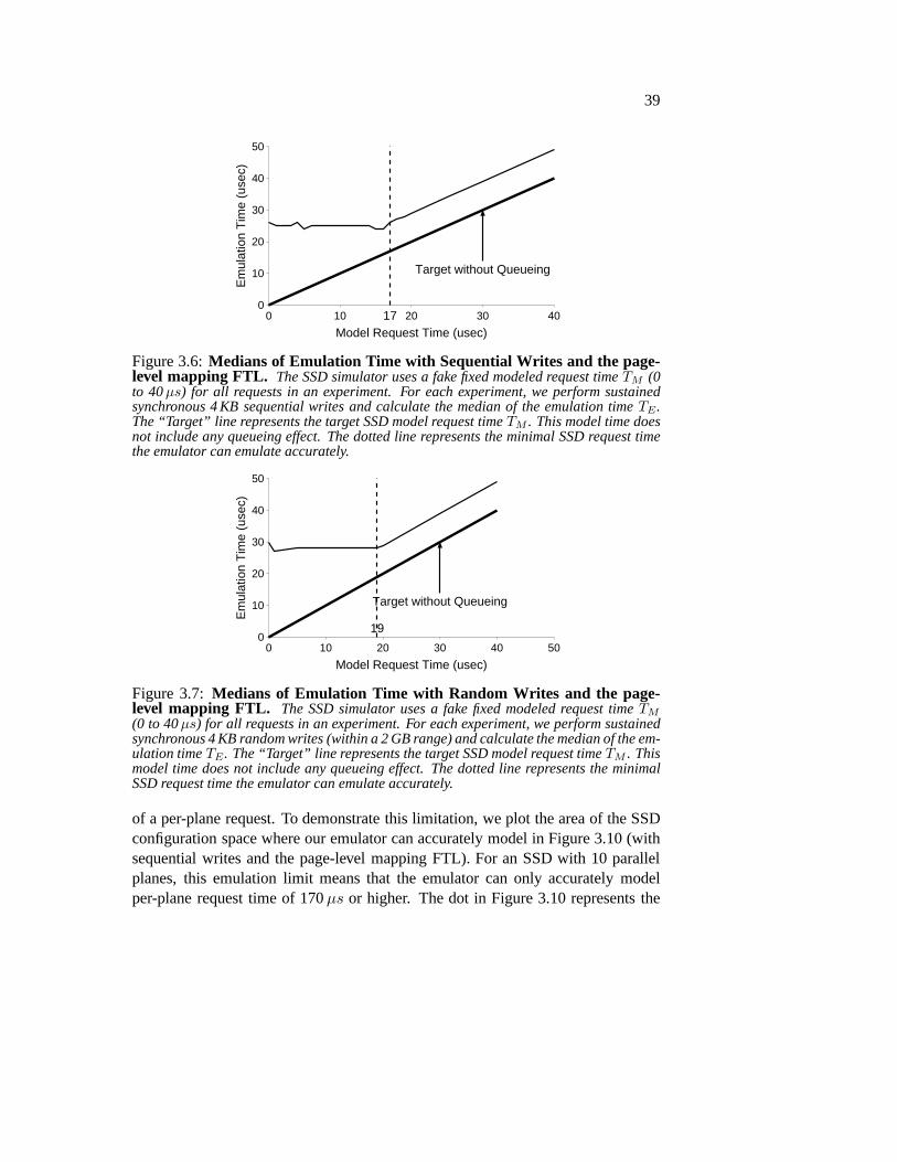
39
Model Request Time (usec)0 10 20 30 40
Em
ulat
ion
Tim
e (u
sec)
0
10
20
30
40
50
Target without Queueing
17
Figure 3.6:Medians of Emulation Time with Sequential Writes and the page-level mapping FTL. The SSD simulator uses a fake fixed modeled request timeTM (0to 40µs) for all requests in an experiment. For each experiment, we perform sustainedsynchronous 4 KB sequential writes and calculate the medianof the emulation timeTE.The “Target” line represents the target SSD model request timeTM . This model time doesnot include any queueing effect. The dotted line representsthe minimal SSD request timethe emulator can emulate accurately.
Model Request Time (usec)0 10 20 30 40 50
Em
ulat
ion
Tim
e (u
sec)
0
10
20
30
40
50
Target without Queueing
19
Figure 3.7: Medians of Emulation Time with Random Writes and the page-level mapping FTL. The SSD simulator uses a fake fixed modeled request timeTM
(0 to 40µs) for all requests in an experiment. For each experiment, we perform sustainedsynchronous 4 KB random writes (within a 2 GB range) and calculate the median of the em-ulation timeTE. The “Target” line represents the target SSD model request timeTM . Thismodel time does not include any queueing effect. The dotted line represents the minimalSSD request time the emulator can emulate accurately.
of a per-plane request. To demonstrate this limitation, we plot the area of the SSDconfiguration space where our emulator can accurately modelin Figure 3.10 (withsequential writes and the page-level mapping FTL). For an SSD with 10 parallelplanes, this emulation limit means that the emulator can only accurately modelper-plane request time of 170µs or higher. The dot in Figure 3.10 represents the
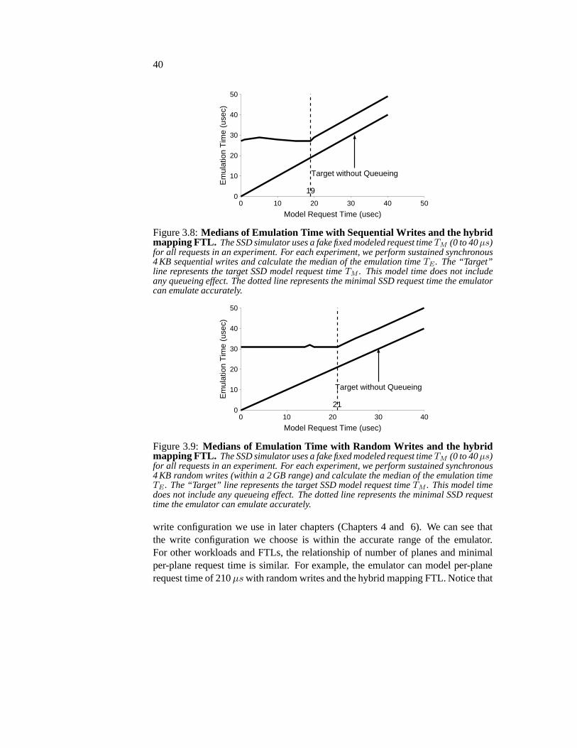
40
Model Request Time (usec)0 10 20 30 40 50
Em
ulat
ion
Tim
e (u
sec)
0
10
20
30
40
50
Target without Queueing
19
Figure 3.8:Medians of Emulation Time with Sequential Writes and the hybridmapping FTL. The SSD simulator uses a fake fixed modeled request timeTM (0 to 40µs)for all requests in an experiment. For each experiment, we perform sustained synchronous4 KB sequential writes and calculate the median of the emulation timeTE. The “Target”line represents the target SSD model request timeTM . This model time does not includeany queueing effect. The dotted line represents the minimalSSD request time the emulatorcan emulate accurately.
Model Request Time (usec)0 10 20 30 40
Em
ulat
ion
Tim
e (u
sec)
0
10
20
30
40
50
Target without Queueing
21
Figure 3.9:Medians of Emulation Time with Random Writes and the hybridmapping FTL. The SSD simulator uses a fake fixed modeled request timeTM (0 to 40µs)for all requests in an experiment. For each experiment, we perform sustained synchronous4 KB random writes (within a 2 GB range) and calculate the median of the emulation timeTE . The “Target” line represents the target SSD model request timeTM . This model timedoes not include any queueing effect. The dotted line represents the minimal SSD requesttime the emulator can emulate accurately.
write configuration we use in later chapters (Chapters 4 and 6). We can see thatthe write configuration we choose is within the accurate range of the emulator.For other workloads and FTLs, the relationship of number of planes and minimalper-plane request time is similar. For example, the emulator can model per-planerequest time of 210µswith random writes and the hybrid mapping FTL. Notice that
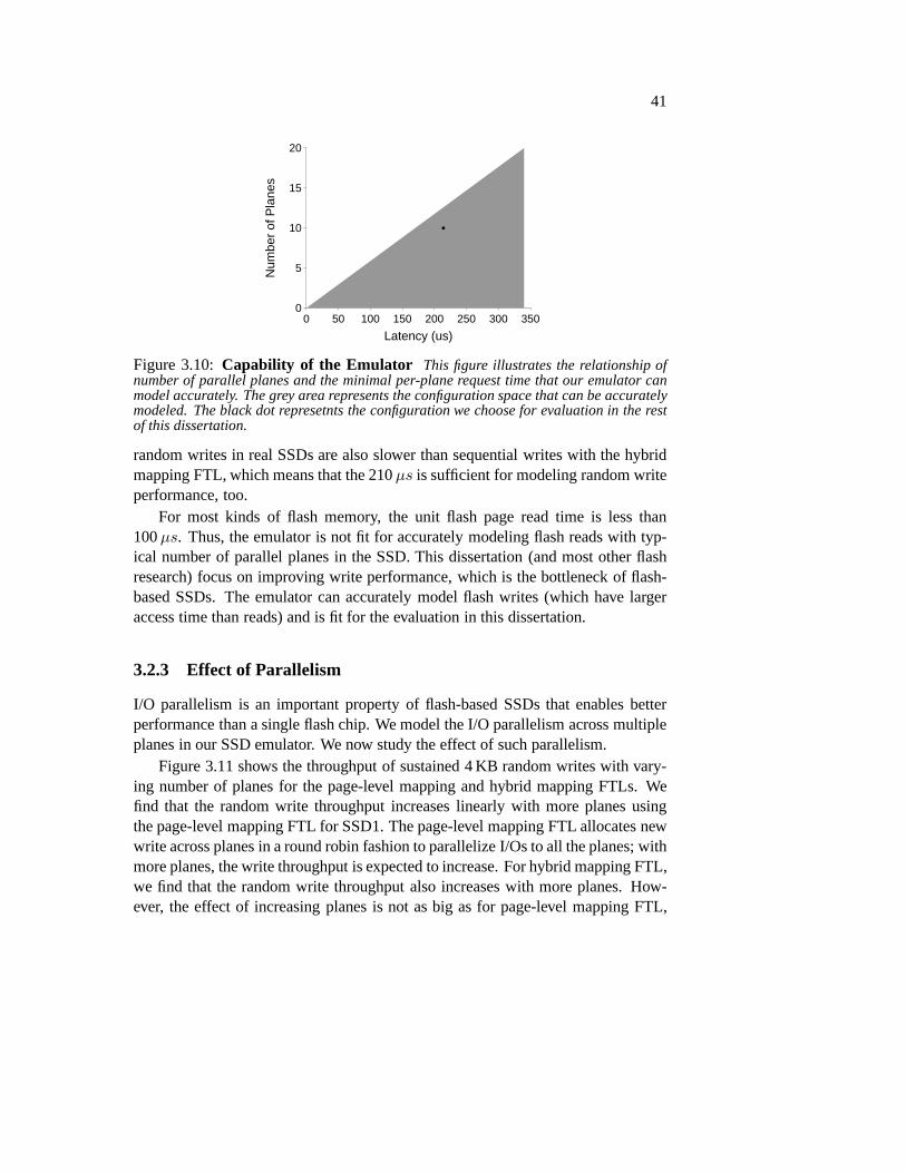
41
Latency (us)0 50 100 150 200 250 300 350
Num
ber
of P
lane
s
0
5
10
15
20
Figure 3.10:Capability of the Emulator This figure illustrates the relationship ofnumber of parallel planes and the minimal per-plane requesttime that our emulator canmodel accurately. The grey area represents the configuration space that can be accuratelymodeled. The black dot represetnts the configuration we choose for evaluation in the restof this dissertation.
random writes in real SSDs are also slower than sequential writes with the hybridmapping FTL, which means that the 210µs is sufficient for modeling random writeperformance, too.
For most kinds of flash memory, the unit flash page read time is less than100µs. Thus, the emulator is not fit for accurately modeling flash reads with typ-ical number of parallel planes in the SSD. This dissertation(and most other flashresearch) focus on improving write performance, which is the bottleneck of flash-based SSDs. The emulator can accurately model flash writes (which have largeraccess time than reads) and is fit for the evaluation in this dissertation.
3.2.3 Effect of Parallelism
I/O parallelism is an important property of flash-based SSDsthat enables betterperformance than a single flash chip. We model the I/O parallelism across multipleplanes in our SSD emulator. We now study the effect of such parallelism.
Figure 3.11 shows the throughput of sustained 4 KB random writes with vary-ing number of planes for the page-level mapping and hybrid mapping FTLs. Wefind that the random write throughput increases linearly with more planes usingthe page-level mapping FTL for SSD1. The page-level mappingFTL allocates newwrite across planes in a round robin fashion to parallelize I/Os to all the planes; withmore planes, the write throughput is expected to increase. For hybrid mapping FTL,we find that the random write throughput also increases with more planes. How-ever, the effect of increasing planes is not as big as for page-level mapping FTL,

42
Number of Planes0 5 10 15 20
Thr
ough
put (
KIO
PS
)
0
10
20
30
40
50
60
70
Page−level_SSD2Page−level_SSD1Hybrid_SSD2Hybrid_SSD1
Figure 3.11:Random Write Throughput with Different Numbers of Planes.Throughput of sustained 4 KB random writes with different numbers of planes for Page-Level and Hybrid FTLs. For each data point, we repeat random writes of a 2 GB file untilthe systems go into a steady state.
Number of Planes0 5 10 15 20
Avg
Lat
ency
(us
)
0
100
200
300
400
500
600
700
800Hybrid_SSD1Hybrid_SSD2Page−level_SSD1Page−level_SSD2
Figure 3.12:Random Write Avg Latency with Different Numbers of Planes.Average latency of sustained 4 KB random writes with different numbers of planes for Page-Level and Hybrid FTLs. For each data point, we repeat random writes of a 2 GB file untilthe systems go into a steady state.
since the major reason for poor hybrid mapping random write performance is itscostly merge operation and this operation has a high performance cost even withmultiple planes.
Looking at SSD2 and the data point from 10 to 20 planes for SSD1, we findthat the write throughput of the SSD emulator flattens at around 65 KIOPS. Thisresult conforms with the SSD emulator performance limitation.
We further look at the average request latencies for different number of planesand plot them in Figure 3.12. We find a similar conclusion as the throughput results:the random write average latency decreases with more planes(linearly for the page-level mapping FTL and sub-linearly for the hybrid mapping FTL).

43
Sequential Random
Thr
ough
put (
MB
/s)
0
50
100
150
200
250
PageSSD1 HybridSSD1 PageSSD2 HybridSSD2
Figure 3.13: Write Performance of the page-level mapping and the hybridmapping FTLs. All experiments are performed with a 4 GB SSD with 10 parallelplanes using two types of flash memory, SSD1 and SSD2. All the experiments use 4 KBblock size and are performed in the 4 GB range.
3.2.4 Comparison of Page-level and Hybrid FTLs
The page-level mapping and hybrid mapping FTLs are two majortypes of FTLsthat differ in the granularity of mappings they maintain (flash page granularity forthe page-level mapping FTL and combination of erase block and flash page gran-ularity for the hybrid mapping FTL). We now present the results of comparing thepage-level mapping and the hybrid mapping FTLs, considering the mapping tablespace they use and their write performance.
The mapping table for the 4 GB SSD is 4 MB with the page-level mapping FTLand is 0.85 MB with the hybrid mapping FTL. The page-level mapping FTL keepsa 32-bit pointer for each 4 KB flash page, making the mapping table size 4 MB. Thehybrid mapping FTL uses 20% log block area and 80% data block area. For thelog block area, it keeps a mapping for each 4 KB page; for the data block area, itkeeps a mapping for each 256 KB erase block, making the total mapping table size0.85 MB. Thus, the page-level mapping FTL uses more mapping table space thanthe hybrid mapping FTL.
Figure 3.13 presents the write performance results of the page-level mappingand hybrid mapping FTLs. The sequential write throughput for the page-level map-ping and hybrid mapping FTLs is similar. But the random writethroughput of thehybrid mapping FTL is much lower than the page-level mappingFTL. We also findthat as expected, SSD2 has higher write throughput than SSD1for both page-levelmapping and hybrid mapping FTLs, since the flash page write latency is lower forSSD2.

44
Cos
t of O
pera
tion
(%)
0
20
40
60
80
100
Amount of Log Blocks (%)0 10 20 30 40 50
IdleMergeIdleMergeReadMergeWriteEraseNormalWrite
Figure 3.14:Cost of Different Operations with Hybrid FTL. Throughput of sus-tained 4 KB random writes with different amount of log blocksin Hybrid FTLs. For eachdata point, we repeat random writes of a 1 GB file until the systems go into a steady state.
3.2.5 Study of Hybrid FTL
Since random writes are the bottleneck of the hybrid mappingFTL, it is impor-tant to learn the cause of its poor random write performance.We now study whatfactors affect random write performance and the reason for the poor random writeperformance.
To closely study random write performance and the operations the FTL usesduring random writes, we break down the FTL utilization intodifferent operations,including normal writes, block erases, writes and reads during merge operations,idle time during merge operations, and other idle time. Figure 3.14 plots the per-centage of all these operations on all the planes during random writes. Figure 3.15takes a close look at the operations other than the idle time.We find that the mergeoperations take the majority of the total SSD time and normalwrites only take uparound 3% to 9% of the total time. As explained in Chapter 2, the merge operationof the hybrid mapping FTL is costly because of the valid data copying and blockerases. Surprisingly, with multiple planes, there is also ahigh idle time during themerge operations. While a data page is copied from a plane during the merge op-eration, other planes can be idle. As a result, the merge operations are the majorreason for poor random writes, even though they are not invoked as often as nor-mal writes (specifically, it is invoked once per 64 4 KB writesto free a 256 KB logblock).
Since the costly merges are triggered when the log block areais full, the sizeof the log block area is likely to affect the random write performance of the hybridmapping FTL. To study this effect, we change the amount of logblocks in Figures3.14 and 3.15. We find that with more log blocks, the amount of normal write
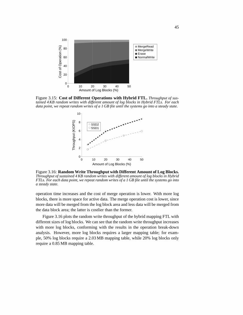
45
Cos
t of O
pera
tion
(%)
0
20
40
60
80
100
Amount of Log Blocks (%)0 10 20 30 40 50
MergeReadMergeWriteEraseNormalWrite
Figure 3.15:Cost of Different Operations with Hybrid FTL. Throughput of sus-tained 4 KB random writes with different amount of log blocksin Hybrid FTLs. For eachdata point, we repeat random writes of a 1 GB file until the systems go into a steady state.
Amount of Log Blocks (%)0 10 20 30 40 50
Thr
ough
put (
KIO
PS
)
0
2
4
6
8
10
SSD2SSD1
Figure 3.16:Random Write Throughput with Different Amount of Log Blocks .Throughput of sustained 4 KB random writes with different amount of log blocks in HybridFTLs. For each data point, we repeat random writes of a 1 GB fileuntil the systems go intoa steady state.
operation time increases and the cost of merge operation is lower. With more logblocks, there is more space for active data. The merge operation cost is lower, sincemore data will be merged from the log block area and less data will be merged fromthe data block area; the latter is costlier than the former.
Figure 3.16 plots the random write throughput of the hybrid mapping FTL withdifferent sizes of log blocks. We can see that the random write throughput increaseswith more log blocks, conforming with the results in the operation break-downanalysis. However, more log blocks requires a larger mapping table; for exam-ple, 50% log blocks require a 2.03 MB mapping table, while 20%log blocks onlyrequire a 0.85 MB mapping table.

46
3.3 Limitations and Discussions
There are certain limitations with our SSD emulator. In thissection we discussthese limitations.
First, our SSD emulator simplifies certain aspects in a real SSD. For example,we do not emulate the write buffer and the read cache available in many modernSSDs. The interface between the SSD emulator and the host OS is also simplifiedto using the Linux kernel block I/O request interface. In reality, SSDs usuallyuse the SATA interface to connect to the host OS and the SATA interface is morecomplicated and restricted than the kernel block I/O interface.
Second, we model SSD FTLs based on previous publications andnot on realSSDs since there is no public information about details of commercial SSD inter-nals. Reverse engineering commercial SSDs may be a viable solution to learn theirinternal FTLs. However, our initial effort to reverse engineer a commercial SSDturns out to be difficult; we leave it for future work.
Third, even though we use different techniques to reduce thecomputationaloverhead of the emulator, such overhead still limits the speed of the emulator andthus the type of SSDs it can emulate accurately. For example,the emulator cannotemulate a fast flash-based SSD with many parallel planes. Forthe same reason, itis difficult to emulate a DRAM-based SSD or other fast deviceswith our emulator.One possible way to alleviate the computational limitationof the emulator is toparallelize the SSD simulator computation across multipleCPU cores.
Finally, our SSD emulator is implemented as a Linux pseudo block driver anddoes not work with other operating systems.
3.4 Summary
In this chapter, we described the SSD emulator that we built for evaluation of vari-ous designs in this dissertation and in other research on SSDs. The emulator worksas a pseudo block device with Linux. Workloads and applications can run easilywith the emulator in a real system. The SSD model we use in the emulator sim-ulates different components and operations of typical modern flash-based SSDs.We implemented two FTLs for the emulator: the page-level mapping FTL and thehybrid mapping FTL.
A major challenge we found in the process of building the emulator is the diffi-culty in making the emulator accurate with SSD models that use internal parallism.We used several different techniques to reduce the computational overhead of theemulator so that it can accurately model important types of metrics with common
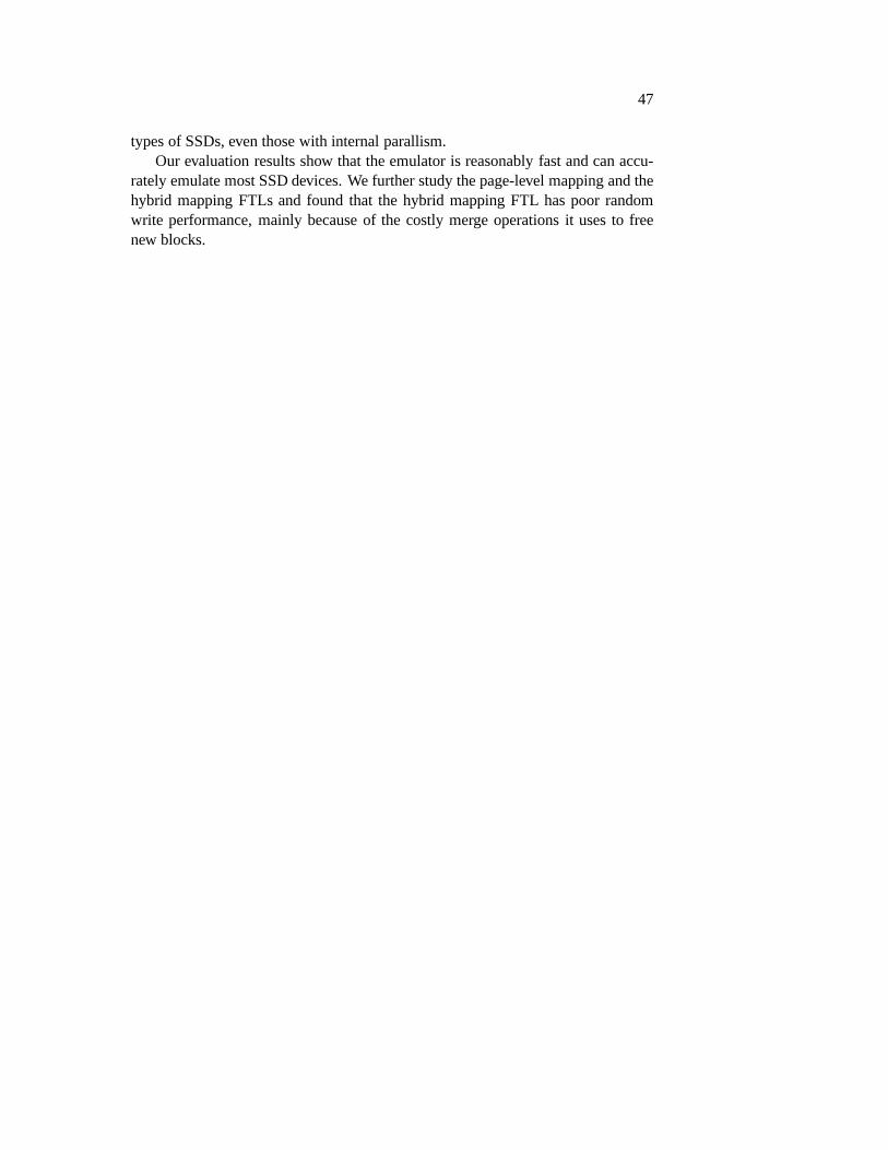
47
types of SSDs, even those with internal parallism.Our evaluation results show that the emulator is reasonablyfast and can accu-
rately emulate most SSD devices. We further study the page-level mapping and thehybrid mapping FTLs and found that the hybrid mapping FTL haspoor randomwrite performance, mainly because of the costly merge operations it uses to freenew blocks.

48

49
Chapter 4
De-indirection with NamelessWrites
When running a file system on top of a flash-based SSD, excess indirection existsin the SSD and creates both memory space and performance overhead. One way toremove such redundant indirection is to remove the need for the SSD to create anduse indirection. Such a goal can be achieved by changing the I/O interface betweenthe file system and the SSD.
In this chapter, we introduce nameless writes, a new I/O interface to removethe costs of the indirection in flash-based SSDs [9, 97]. A nameless write sendsonly data and no name (i.e., logical block address) to the device. The device thenperforms its allocation and writes the data to a physical block address. The physicalblock address is then sent back to the file system by the deviceand the file systemrecords it in its metadata for future reads.
In designing the nameless writes interface, we encounteredtwo major chal-lenges. First, flash-based SSDs migrate physical blocks because of garbage col-lection and wear leveling; the file system needs to be informed about such addresschange so that future reads can be directed properly. Second, if we use namelesswrites as the only write interface, then there will be a high performance cost and in-creased engineering complexity because of the behavior of recursive updates alongthe file system tree.
We solve the first problem with amigration callback, which informs physicaladdress changes to the file system, which then updates its metadata to reflect thechanges. We solve the second problem by treating file system metadata and datadifferently and use traditional writes for metadata and nameless writes for data; thephysical addresses of metadata thus do not need to be returned or recorded in the

50
file system, stopping the recursive updates.We built an emulated nameless-writing SSD and ported the Linux ext3 file sys-
tem to nameless writes. Our evaluation results of nameless writes and its compar-ison with other FTLs show that a nameless-writing SSD uses much less memoryspace for indirection and improves random write performance significantly as com-pared to the SSD with the hybrid FTL.
The rest of this chapter is organized as follows. In Section 4.1 we presentthe design of the nameless write interface.In Section 4.2, we show how to build anameless-writing device. In Section 4.3, we describe how toport the Linux ext3file system to use the nameless-writing interface, and in Section 4.4, we evaluatenameless writes through experimentation atop an emulated nameless-writing de-vice. Finally, we summarizes this chapter in Section 4.5.
4.1 Nameless Writes
In this section, we discuss a new device interface that enables flash-based SSDsto remove a great deal of their infrastructure for indirection. We call a devicethat supports this interface aNameless-writing Device. Table 4.1 summarizes thenameless-writing device interfaces.
The key feature of a nameless-writing device is its ability to perform namelesswrites; however, to facilitate clients (such as file systems) to use a nameless-writingdevice, a number of other features are useful as well. In particular, the nameless-writing device should provide support for a segmented address space, migrationcallbacks, and associated metadata. We discuss these features in this section andhow a prototypical file system could use them.
4.1.1 Nameless Write Interfaces
We first present the basic device interfaces ofNameless Writes: nameless (new)write, nameless overwrite, physical read, and free.
The nameless write interface completely replaces the existing write operation.A nameless write differs from a traditional write in two important ways. First, anameless write does not specify a target address (i.e., a name); this allows the deviceto select the physical location without control from the client above. Second, afterthe device writes the data, it returns aphysicaladdress (i.e., a name) and status tothe client, which then keeps the name in its own structure forfuture reads.
The nameless overwrites interface is similar to the nameless (new) write inter-face, except that it also passes the old physical address(es) to the device. The device

51
Virtual Readdown: virtual address, lengthup: status, data
Virtual Writedown: virtual address, data, lengthup: status
Nameless Writedown: data, length, metadataup: status, resulting physical address(es)
Nameless Overwritedown: old physical address(es), data, length, metadataup: status, resulting physical address(es)
Physical Readdown: physical address, length, metadataup: status, data
Freedown: virtual/physical addr, length, metadata, flagup: status
Migration [Callback]up: old physical addr, new physical addr, metadatadown: old physical addr, new physical addr, metadata
Table 4.1: The Nameless-Writing Device Interfaces. The table presents thenameless-writing device interfaces.
frees the data at the old physical address(es) and then performs a nameless write.
Read operations are mostly unchanged; as usual, they take asinput the physicaladdress to be read and return the data at that address and a status indicator. A slightchange of the read interface is the addition of metadata in the input, for reasons thatwill be described in Section 4.1.4.
Because a nameless write is an allocating operation, a nameless-writing deviceneeds to also be informed of de-allocation as well. Most SSDsrefer to this interfaceas thefreeor trim command. Once a block has been freed (trimmed), the device isfree to re-use it.
Finally, we consider how the nameless write interface couldbe utilized by atypical file-system client such as Linux ext3. For illustration, we examine the op-erations to append a new block to an existing file. First, the file system issues

52
a nameless write of the newly-appended data block to a nameless-writing device.When the nameless write completes, the file system is informed of its address andcan update the corresponding in-memory inode for this file sothat it refers to thephysical address of this block. Since the inode has been changed, the file systemwill eventually flush it to the disk as well; the inode must be written to the devicewith another nameless write. Again, the file system waits forthe inode to be writ-ten and then updates any structures containing a reference to the inode. If namelesswrites are the only interface available for writing to the storage device, then thisrecursion will continue until a root structure is reached. For file systems that donot perform this chain of updates or enforce such ordering, such as Linux ext2,additional ordering and writes are needed. This problem of recursive update hasbeen solved in other systems by adding a level of indirection(e.g., the inode mapin LFS [77]).
4.1.2 Segmented Address Space
To solve the recursive update problem without requiring substantial changes tothe existing file system, we introduce a segmented address space with two seg-ments (see Figure 4.1): thevirtual address space, which uses virtual read, virtualwrite and free interfaces, and thephysical address space, which uses physical read,nameless write and overwrite, and free interfaces.
The virtual segment presents an address space from blocks 0 throughV − 1,and is a virtual block space of sizeV blocks. The device virtualizes this addressspace, and thus keeps a (small) indirection table to map accesses to the virtual spaceto the correct underlying physical locations. Reads and writes to the virtual spaceare identical to reads and writes on typical devices. The client sends an address anda length (and, if a write, data) down to the device; the devicereplies with a statusmessage (success or failure), and if a successful read, the requested data.
The nameless segment presents an address space from blocks 0throughP − 1,and is a physical block space of sizeP blocks. The bulk of the blocks in thedevice are found in this physical space, which allows typical named reads; however,all writes to physical space are nameless, thus preventing the client from directlywriting to physical locations of its choice.
We use a virtual/physical flag to indicate the segment a blockis in and theproper interfaces it should go through. The size of the two segments are not fixed.Allocation in either segment can be performed while there isstill space on thedevice. A device space usage counter can be maintained for this purpose.
The reason for the segmented address space is to enable file systems to largelyreduce the levels of recursive updates that would occur withonly nameless writes.

53
V0 V1 V2 V3 P0 P1 P2 P3 P4 P5 P6 P7 P8 P9
Virtual Address Space Physical Address Space
Virtual Reads
Virtual Writes
Physical Reads
Nameless Writes
P0 P1 P2 P3 P4 P5 P6 P7 P8 P9
V0 → P2
V2 → P3
indirection
table
Figure 4.1:The Segmented Address Space.A nameless-writing device provides asegmented address space to clients. The smaller virtual space allows normal reads andwrites, which the device in turn maps to underlying physicallocations. The larger physicalspace allows reads to physical addresses, but only namelesswrites. In the example, onlytwo blocks of the virtual space are currently mapped, V0 and V2, to physical blocks P2 andP3, respectively.
File systems such as ext2 and ext3 can be designed such that inodes and othermetadata are placed in the virtual address space. Such file systems can simplyissue a write to an inode and complete the update without needing to modify direc-tory structures that reference the inode. Thus, the segmented address space allowsupdates to complete without propagating throughout the directory hierarchy.
4.1.3 Migration Callback
Several kinds of devices such as flash-based SSDs need to migrate data for reasonslike wear leveling. We propose themigration callbackinterface to support suchneeds.
A typical flash-based SSD performs wear leveling via indirection: it simplymoves the physical blocks and updates the map. With namelesswrites, blocks inthe physical segment cannot be moved without informing the file system. To allowthe nameless-writing device to move data for wear leveling,a nameless-writingdevice usesmigration callbacksto inform the file system of the physical addresschange of a block. The file system then updates any metadata pointing to thismigrated block.
54
4.1.4 Associated Metadata
The final interface of a nameless-writing device is used to enable the client toquickly locate metadata structures that point to data blocks. The complete spec-ification for associated metadata supports communicating metadata between theclient and device. Specifically, the nameless write commandis extended to includea third parameter: a small amount of metadata, which is persistently recorded ad-jacent to the data in a per-block header. Reads and migrationcallbacks are alsoextended to include this metadata. The associated metadatais kept with each blockbuffer in the page cache as well.
This metadata enables the client file system to readily identify the metadatastructure(s) that points to a data block. For example, in ext3 we can locate themetadata structure that points to a data block by the inode number, the inode gener-ation number, and the offset of the block in the inode. For filesystems that alreadyexplicitly record back references, such as btrfs and NoFS [23], the back referencescan simply be reused for our purposes.
Such metadata structure identification can be used in several tasks. First, whensearching for a data block in the page cache, we obtain the metadata informationand compare it against the associated metadata of the data blocks in the page cache.Second, the migration callback process uses associated metadata to find the meta-data that needs to be updated when a data block is migrated. Finally, associatedmetadata enables recovery in various crash scenarios, which we will discuss in de-tail in Section 4.3.7.
One last issue worth noticing is the difference between the associated meta-data and address mapping tables. Unlike address mapping tables, the associatedmetadata is not used to locate physical data and is only used by the device dur-ing migration callbacks and crash recovery. Therefore, it can be stored adjacent tothe data on the device. Only a small amount of the associated metadata is fetchedinto device cache for a short period of time during migrationcallbacks or recov-ery. Therefore, the space cost of associated metadata is much smaller than addressmapping tables.
4.1.5 Implementation Issues
We now discuss various implementation issues that arise in the construction of anameless-writing device. We focus on those issues different from a standard SSD,which are covered in detail elsewhere [40].
A number of issues revolve around the virtual segment. Most importantly, howbig should such a segment be? Unfortunately, its size depends heavily on how the

55
client uses it, as we will see when we port Linux ext3 to use nameless writes inSection 4.3. Our results in Section 4.4 show that a small virtual segment is usuallysufficient.
The virtual space, by definition, requires an in-memory indirection table. For-tunately, this table is quite small, likely including simple page-level mappings foreach page in the virtual segment. However, the virtual address space could be madelarger than the size of the table; in this case, the device would have to swap pieces ofthe page table to and from the device, slowing down access to the virtual segment.Thus, while putting many data structures into the virtual space is possible, ideallythe client should be miserly with the virtual segment, in order to avoid exceedingthe supporting physical resources.
Another concern is the extra level of information naturallyexported by expos-ing physical names to clients. Although the value of physical names has been ex-tolled by others [27], a device manufacturer may feel that such information revealstoo much of their “secret sauce” and thus be wary of adopting such an interface.We believe that if such a concern exists, the device could hand out modified formsof the true physical addresses, thus trying to hide the exactaddresses from clients.Doing so may exact additional performance and space overheads, perhaps the costof hiding information from clients.
4.2 Nameless-Writing Device
In this section, we describe our implementation of an emulated nameless-writingSSD. With nameless writes, a nameless-writing SSD can have asimpler FTL,which has the freedom to do its own allocation and wear leveling. We first dis-cuss how we implement the nameless-writing interfaces and then propose a newgarbage collection method that avoids file-system interaction. We defer the discus-sion of wear leveling to Section 4.3.6.
4.2.1 Nameless-Writing Interface Support
We implemented an emulated nameless-writing SSD that performs data allocationin a log-structured fashion by maintaining active blocks that are written in sequen-tial order. When a nameless write is received, the device allocates the next freephysical address, writes the data, and returns the physicaladdress to the file sys-tem.
To support the virtual block space, the nameless-writing device maintains amapping table between logical and physical addresses in itsdevice cache. When
56
the cache is full, the mapping table is swapped out to the flashstorage of the SSD.As our results show in Section 4.4.1, the mapping table size of typical file systemimages is small; thus, such swapping rarely happens in practice.
The nameless-writing device handles trims in a manner similar to traditionalSSDs; it invalidates the physical address sent by a trim command. During garbagecollection, invalidated pages can be recycled. The device also invalidates the oldphysical addresses of overwrites.
A nameless-writing device needs to keep certain associatedmetadata for name-less writes. We choose to store the associated metadata of a data page in its Out-Of-Band (OOB) area. The associated metadata is moved together with data pageswhen the device performs a migration.
4.2.2 In-place Garbage Collection
In this section, we describe a new garbage collection methodfor nameless-writingdevices. Traditional FTLs perform garbage collection on a flash block by reclaim-ing its invalid data pages and migrating its live data pages to new locations. Suchgarbage collection requires a nameless-writing device to inform the file system ofthe new physical addresses of the migrated live data; the filesystem then needs toupdate and write out its metadata. To avoid the costs of such callbacks and addi-tional metadata writes, we proposein-place garbage collection, which writes thelive data back to the same location instead of migrating it. Asimilar hole-pluggingapproach was proposed in earlier work [66], where live data is used to plug theholes of most utilized segments.
To perform in-place garbage collection, the FTL selects a candidate block usinga certain policy. The FTL reads all live pages from the chosenblock together withtheir associated metadata, stores them temporarily in a super-capacitor- or battery-backed cache, and then erases the block. The FTL next writes the live pages to theiroriginal addresses and tries to fill the rest of the block withwrites in the waitingqueue of the device. Since a flash block can only be written in one direction, whenthere are no waiting writes to fill the block, the FTL marks thefree space in theblock as unusable. We call such spacewasted space. During in-place garbagecollection, the physical addresses of live data are not changed. Thus, no file systeminvolvement is needed.
Policy to choose candidate block: A natural question is how to choose blocksfor garbage collection. A simple method is to pick blocks with the fewest livepages so that the cost of reading and writing them back is minimized. However,choosing such blocks may result in an excess of wasted space.In order to pick

57
a good candidate block for in-place garbage collection, we aim to minimize thecost of rewriting live data and to reduce wasted space duringgarbage collection.We propose an algorithm that tries to maximize the benefit andminimize the costof in-place garbage collection. We define the cost of garbagecollecting a blockto be the total cost of erasing the block (Terase), reading (Tpage read) and writing(Tpage write) live data (Nvalid) in the block.
cost = Terase + (Tpage read + Tpage write) ∗Nvalid
We define benefit as the number of new pages that can potentially be writtenin the block. Benefit includes the following items: the current number of waitingwrites in the device queue (Nwait write), which can be filled into empty pages im-mediately, the number of empty pages at the end of a block (Nlast), which can befilled at a later time, and an estimated number of future writes based on the speedof incoming writes (Swrite). While writing valid pages (Nvalid) and waiting writes(Nwait write), new writes will be accumulated in the device queue. We account forthese new incoming writes byTpage write ∗ (Nvalid +Nwait write) ∗ Swrite. Sincewe can never write more than the amount of the recycled space (i.e., number ofinvalid pages,Ninvalid) of a block, the benefit function uses the minimum of thenumber of invalid pages and the number of all potential new writes.
benefit = min(Ninvalid, Nwait write +Nlast (4.1)
+Tpage write ∗ (Nvalid +Nwait write) ∗ Swrite) (4.2)
The FTL calculates thebenefitcost
ratio of all blocks that contain invalid pagesand selects the block with the maximal ratio to be the garbagecollection candi-date. Computationally less expensive algorithms could be used to find reasonableapproximations; such an improvement is left to future work.
4.3 Nameless Writes on ext3
In this section we discuss our implementation of nameless writes on the Linux ext3file system with its ordered journal mode. The ordered journaling mode of ext3 isa commonly used mode, which writes metadata to the journal and writes data todisk before committing metadata of the transaction. It provides ordering that canbe naturally used by nameless writes, since the nameless-writing interface requiresmetadata to reflect physical address returned by data writes. When committingmetadata in ordered mode, the physical addresses of data blocks are known to the

58
file system because data blocks are written out first.
4.3.1 Segmented Address Space
We first discuss physical and virtual address space separation and modified file-system allocation on ext3. We use the physical address spaceto store all datablocks and the virtual address space to store all metadata structures, including su-perblocks, inodes, data and inode bitmaps, indirect blocks, directory blocks, andjournal blocks. We use the type of a block to determine whether it is in the virtualor the physical address space and the type of interfaces it goes through.
The nameless-writing file system does not perform allocation of the physicaladdress space and only allocates metadata in the virtual address space. Therefore,we do not fetch or update group bitmaps for nameless block allocation. For thesedata blocks, the only bookkeeping task that the file system needs to perform istracking overall device space usage. Specifically, the file system checks for totalfree space of the device and updates the free space counter when a data block isallocated or de-allocated. Metadata blocks in the virtual physical address spaceare allocated in the same way as the original ext3 file system,thus making use ofexisting bitmaps.
4.3.2 Associated Metadata
We include the following items as associated metadata of a data block: 1) the inodenumber or the logical address of the indirect block that points to the data block, 2)the offset within the inode or the indirect block, 3) the inode generation number,and 4) a timestamp of when the data block is last updated or migrated. Items 1 to3 are used to identify the metadata structure that points to adata block. Item 4 isused during the migration callback process to update the metadata structure withthe most up-to-date physical address of a data block.
All the associated metadata is stored in the OOB area of a flashpage. The totalamount of additional status we store in the OOB area is less than 48 bytes, smallerthan the typical 128-byte OOB size of 4-KB flash pages. For reliability reasons, werequire that a data page and its OOB area are always written atomically.
4.3.3 Write
To perform a nameless write, the file system sends the data andthe associatedmetadata of the block to the device. When the device finishes anameless write andsends back its physical address, the file system updates the inode or the indirect
59
block pointing to it with the new physical address. It also updates the block bufferwith the new physical address. In ordered journaling mode, metadata blocks arealways written after data blocks have been committed; thus on-disk metadata isalways consistent with its data. The file system performs overwrites similarly. Theonly difference is that overwrites have an existing physical address, which is sentto the device; the device uses this information to invalidate the old data.
4.3.4 Read
We change two parts of the read operation of data blocks in thephysical addressspace: reading from the page cache and reading from the physical device. To searchfor a data block in the page cache, we compare the metadata index (e.g., inodenumber, inode generation number, and block offset) of the block to be read againstthe metadata associated with the blocks in the page cache. Ifthe buffer is not inthe page cache, the file system fetches it from the device using its physical address.The associated metadata of the data block is also sent with the read operation toenable the device to search for remapping entries during device wear leveling (seeSection 4.3.6).
4.3.5 Free
The current Linux ext3 file system does not support the SSD trim operation. Weimplemented the ext3 trim operation in a manner similar to ext4. Trim entries arecreated when the file system deletes a block (named or nameless). A trim entrycontains the logical address of a named block or the physicaladdress of a namelessblock, the length of the block, its associated metadata, andthe address space flag.The file system then adds the trim entry to the current journaltransaction. At theend of transaction commit, all trim entries belonging to thetransaction are sentto the device. The device locates the block to be deleted using the informationcontained in the trim operation and invalidates the block.
When a metadata block is deleted, the original ext3 de-allocation process is per-formed. When a data block is deleted, no de-allocation is performed (i.e., bitmapsare not updated); only the free space counter is updated.
4.3.6 Wear Leveling with Callbacks
When a nameless-writing device performs wear leveling, it migrates live data toachieve even wear of the device. When such migration happenswith data blocks inthe physical address space, the file system needs to be informed about the change

60
of their physical addresses. In this section, we describe how the nameless-writingdevice handles data block migration and how it interacts with the file system toperformmigration callbacks.
When live nameless data blocks (together with their associated metadata in theOOB area) are migrated during wear leveling, the nameless-writing device createsa mapping from the data block’s old physical address to its new physical addressand stores it together with its associated metadata in amigration remapping tablein the device cache. The migration remapping table is used tolocate the migratedphysical address of a data block for reads and overwrites, which may be sent to thedevice with the block’s old physical address. After the mapping has been added,the old physical address is reclaimed and can be used by future writes.
At the end of a wear-leveling operation, the device sends a migration callbackto the file system, which contains all migrated physical addresses and their asso-ciated metadata. The file system then uses the associated metadata to locate themetadata pointing to the data block and updates it with the new physical addressin a background process. Next, the file system writes changedmetadata to the de-vice. When a metadata write finishes, the file system deletes all the callback entriesbelonging to this metadata block and sends a response to the device, informingit that the migration callback has been processed. Finally,the device deletes theremapping entry when receiving the response of a migration callback.
For migrated metadata blocks, the file system does not need tobe informed ofthe physical address change since it is kept in the virtual address space. Thus, thedevice does not keep remapping entries or send migration callbacks for metadatablocks.
During the migration callback process, we allow reads and overwrites to themigrated data blocks. When receiving a read or an overwrite during the callbackperiod, the device first looks in the migration remapping table to locate the currentphysical address of the data block and then performs the request.
Since all remapping entries are stored in the on-device RAM before the filesystem finishes processing the migration callbacks, we may run out of RAM spaceif the file system does not respond to callbacks or responds too slowly. In such acase, we simply prohibit future wear-leveling migrations until file system respondsand prevent block wear-out only through garbage collection.
4.3.7 Reliability Discussion
The changes of the ext3 file system discussed above may cause new reliabilityissues. In this section, we discuss several reliability issues and our solutions tothem.
61
There are three main reliability issues related to namelesswrites. First, wemaintain a mapping table in the on-device RAM for the virtualaddress space. Thistable needs to be reconstructed each time the device powers on (either after a normalpower-off or a crash). Second, the in-memory metadata can beinconsistent withthe physical addresses of nameless blocks because of a crashafter writing a datablock and before updating its metadata block, or because of acrash during wear-leveling callbacks. Finally, crashes can happen during in-place garbage collection,specifically, after reading the live data and before writingit back, which may causedata loss.
We solve the first two problems by using the metadata information maintainedin the device OOB area. We store logical addresses with data pages in the virtualaddress space for reconstructing the logical-to-physicaladdress mapping table. Westore associated metadata, as discussed in Section 4.1.4, with all nameless data. Wealso store the validity of all flash pages in their OOB area. Wemaintain an invariantthat metadata in the OOB area is always consistent with the data in the flash pageby writing the OOB area and the flash page atomically.
We solve the in-place garbage collection reliability problem by requiring theuse of a small memory backed by battery or super-capacitor. Notice that the amountof live data we need to hold during a garbage collection operation is no more thanthe size of an SSD block, typically 256 KB, thus only adding a small monetary costto the whole device.
The recovery process works as follows. When the device is started, we performa whole-device scan and read the OOB area of all valid flash pages to reconstructthe mapping table of the virtual address space. If a crash is detected, we performthe following steps. The device sends the associated metadata in the OOB areaand the physical addresses of flash pages in the physical address space to the filesystem. The file system then locates the proper metadata structures. If the physicaladdress in a metadata structure is inconsistent, the file system updates it with thenew physical address and adds the metadata write to a dedicated transaction. Afterall metadata is processed, the file system commits the transaction, at which pointthe recovery process is finished.
4.4 Evaluation
In this section, we present our evaluation of nameless writes on an emulated nameless-writing device. Specifically, we focus on studying the following questions:
• What are the memory space costs of nameless-writing devicescompared toother FTLs?

62
Configuration ValueSSD Size 4 GBPage Size 4 KBBlock Size 256 KBNumber of Planes 10Hybrid Log Block Area 5%Page Read Latency 25µsPage Write Latency 200µsBlock Erase Latency 1500µsBus Control Delay 2µsBus Data Delay 10µsRAM Read/Write Delay 1µsPlane Register Read/Write Delay 1µs
Table 4.2:SSD Emulator Configuration. This table presents the configuration weused in our SSD emulator. The components for each configuration can be found in Fig-ure 3.2
• What is the overall performance benefit of nameless-writingdevices?
• What is the write performance of nameless-writing devices?How and whyis it different from page-level mapping and hybrid mapping FTLs?
• What are the costs of in-place garbage collection and the overheads of wear-leveling callbacks?
• Is crash recovery correct and what are its overheads?
We implemented the emulated nameless-writing device with our SSD emulatordescribed in Chapter 3. We compare the nameless-writing FTLto both page-levelmapping and hybrid mapping FTLs. We implemented the emulated nameless-writing SSD and the nameless-writing ext3 file system on a 64-bit Linux 2.6.33kernel. The page-level mapping and the hybrid mapping SSD emulators are builton an unmodified 64-bit Linux 2.6.33 kernel. All experimentsare performed on a2.5 GHz Intel Quad Core CPU with 8 GB memory.
4.4.1 SSD Memory Consumption
We first study the space cost of mapping tables used by different SSD FTLs: nameless-writing, page-level mapping, and hybrid mapping. The mapping table size of page-level and hybrid FTLs is calculated based on the total size ofthe device, its block

63
Image Size Page Hybrid Nameless328 MB 328 KB 38 KB 2.7 KB
2 GB 2 MB 235 KB 12 KB10 GB 10 MB 1.1 MB 31 KB
100 GB 100 MB 11 MB 251 KB400 GB 400 MB 46 MB 1 MB
1 TB 1 GB 118 MB 2.2 MB
Table 4.3:FTL Mapping Table Size. Mapping table size of page-level, hybrid, andnameless-writing devices with different file system images. The configuration in Table 4.2is used.
size, and its log block area size (for hybrid mapping). A nameless-writing devicekeeps a mapping table for the entire file system’s virtual address space. Since wemap all metadata to the virtual block space in our nameless-writing implementa-tion, the mapping table size of the nameless-writing deviceis dependent on themetadata size of the file system image. We use Impressions [4]to create typical filesystem images of sizes up to 1 TB and calculate their metadatasizes.
Table 4.3 shows the mapping table sizes of the three FTLs withdifferent filesystem images produced by Impressions. Unsurprisingly, the page-level mappinghas the highest mapping table space cost. The hybrid mappinghas a moderatespace cost; however, its mapping table size is still quite large: over 100 MB for a1-TB device. The nameless mapping table has the lowest spacecost; even for a 1-TB device, its mapping table uses less than 3 MB of space for typical file systems,reducing both cost and power usage.
4.4.2 Application Performance
We now present the overall application performance of nameless-writing, page-level mapping and hybrid mapping FTLs with macro-benchmarks. We use varmail,fileserver, and webserver from the filebench suite [83].
Figure 4.2 shows the throughput of these benchmarks. We see that both page-level mapping and nameless-writing FTLs perform better than the hybrid mappingFTL with varmail and fileserver. These benchmarks contain 90.8% and 70.6%random writes, respectively. As we will see later in this section, the hybrid mappingFTL performs well with sequential writes and poorly with random writes. Thus,its throughput for these two benchmarks is worse than the other two FTLs. Forwebserver, all three FTLs deliver similar performance, since it contains only 3.8%random writes. We see a small overhead of the nameless-writing FTL as compared

64
Varmail FileServer WebServerT
hrou
ghpu
t (M
B/s
)
0
100
200
300
400
500
600
Page Nameless Hybrid
Figure 4.2:Throughput of Filebench. Throughput of varmail, fileserver, and webmailmacro-benchmarks with page-level, nameless-writing, andhybrid FTLs.
Sequential Random
Thr
ough
put (
KIO
PS
)
0
10
20
30
40
50
Page Nameless Hybrid5% Hybrid10% Hybrid20%
Figure 4.3:Sequential and Random Write Throughput. Throughput of sequentialwrites and sustained 4-KB random writes. Random writes are performed over a 2-GBrange.
to the page-level mapping FTL with all benchmarks, which we will discuss in detailin Sections 4.4.5 and 4.4.6.
In summary, we demonstrate that the nameless-writing device achieves excel-lent performance, roughly on par with the costly page-levelapproach, which servesas an upper-bound on performance.

65
4.4.3 Basic Write Performance
Write performance of flash-based SSDs is known to be much worse than read per-formance, with random writes being the performance bottleneck. Nameless writesaim to improve write performance of such devices by giving the device more data-placement freedom. We evaluate the basic write performanceof our emulatednameless-writing device in this section. Figure 4.3 shows the throughput of se-quential writes and sustained 4-KB random writes with page-level mapping, hybridmapping, and nameless-writing FTLs.
First, we find that the emulated hybrid-mapping device has a sequential through-put of 169 MB/s and a sustained 4-KB random write throughput of 2,830 IOPS. Awidely used real middle-end SSD has sequential throughput of up to 70 MB/s andrandom throughput of up to 3,300 IOPS [44].
Second, the random write throughput of page-level mapping and nameless-writing FTLs is close to their sequential write throughput,because both FTLs allo-cate data in a log-structured fashion, making random writesbehave like sequentialwrites. The overhead of random writes with these two FTLs comes from theirgarbage collection process. Since whole blocks can be erased when they are over-written in sequential order, garbage collection has the lowest cost with sequentialwrites. By contrast, garbage collection of random data may incur the cost of livedata migration.
Third, we notice that the random write throughput of the hybrid mapping FTLis significantly lower than that of the other FTLs and its own sequential writethroughput. The poor random write performance of the hybridmapping FTL re-sults from the costly full-merge operation and its corresponding garbage collectionprocess [40]. Full merges are required each time a log block is filled with randomwrites, thus a dominating cost for random writes.
One way to improve the random write performance of hybrid-mapped SSDs isto over-provision more log block space. To explore that, we vary the size of thelog block area with the hybrid mapping FTL from 5% to 20% of thewhole deviceand found that random write throughput gets higher as the size of the log blockarea increases. However, only the data block area reflects the effective size of thedevice, while the log block area is part of device over-provisioning. Therefore,hybrid-mapped SSDs often sacrifice device space cost for better random write per-formance. Moreover, the hybrid mapping table size increases with higher log blockspace, requiring larger on-device RAM. Nameless writes achieve significantly bet-ter random write performance with no additional over-provisioning or RAM space.
Finally, Figure 4.3 shows that the nameless-writing FTL haslow overhead ascompared to the page-level mapping FTL with sequential and random writes. We
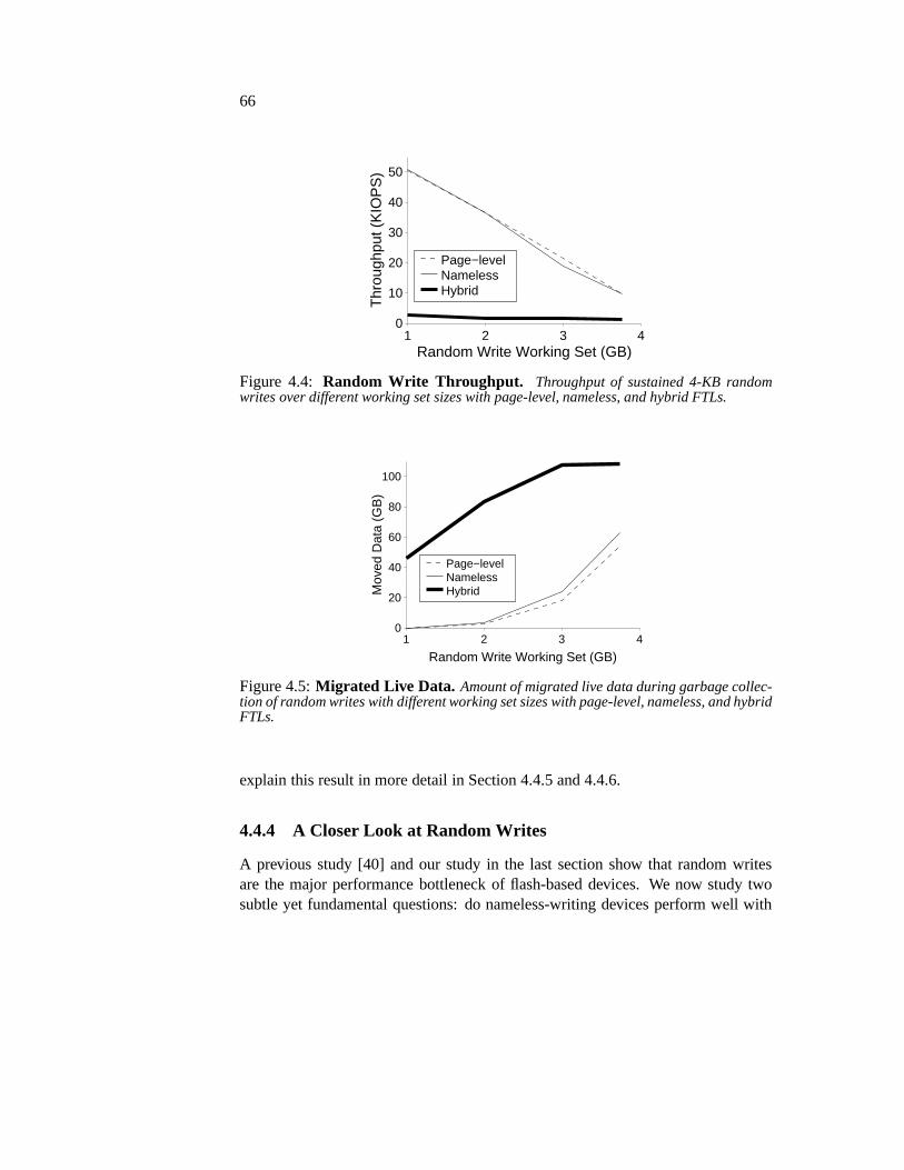
66
Random Write Working Set (GB)1 2 3 4
Thr
ough
put (
KIO
PS
)
0
10
20
30
40
50
Page−levelNamelessHybrid
Figure 4.4: Random Write Throughput. Throughput of sustained 4-KB randomwrites over different working set sizes with page-level, nameless, and hybrid FTLs.
Random Write Working Set (GB)1 2 3 4
Mov
ed D
ata
(GB
)
0
20
40
60
80
100
Page−levelNamelessHybrid
Figure 4.5:Migrated Live Data. Amount of migrated live data during garbage collec-tion of random writes with different working set sizes with page-level, nameless, and hybridFTLs.
explain this result in more detail in Section 4.4.5 and 4.4.6.
4.4.4 A Closer Look at Random Writes
A previous study [40] and our study in the last section show that random writesare the major performance bottleneck of flash-based devices. We now study twosubtle yet fundamental questions: do nameless-writing devices perform well with

67
Cos
t of O
pera
tion
(%)
0
20
40
60
80
100
Random Write Working Set (GB)1 2 3 4
IdleMerge ReadMerge WriteEraseNormal Write
Cos
t of O
pera
tion
(%)
0
20
40
60
80
100
Random Write Working Set (GB)1 2 3 4
Cos
t of O
pera
tion
(%)
0
20
40
60
80
100
Random Write Working Set (GB)1 2 3 4
Figure 4.6:Device Utilization. Break down of device utilization with the page-level,the nameless, and the hybrid FTLs under random writes of different ranges.
different kinds of random-write workloads, and why do they outperform hybriddevices.
To answer the first question, we study the effect of working set size on randomwrites. We create files of different sizes and perform sustained 4-KB random writesin each file to model different working set sizes. Figure 4.4 shows the throughput ofrandom writes over different file sizes with all three FTLs. We find that the work-ing set size has a large effect on random write performance ofnameless-writing andpage-level mapping FTLs. The random write throughput of these FTLs drops as theworking set size increases. When random writes are performed over a small work-ing set, they will be overwritten in full when the device fillsand garbage collectionis triggered. In such cases, there is a higher chance of finding blocks that are filledwith invalid data and can be erased with no need to rewrite live data, thus loweringthe cost of garbage collection. In contrast, when random writes are performed overa large working set, garbage collection has a higher cost since blocks contain morelive data, which must be rewritten before erasing a block.
To further understand the increasing cost of random writes as the working setincreases, we plot the total amount of live data migrated during garbage collection(Figure 4.5) of random writes over different working set sizes with all three FTLs.This graph shows that as the working set size of random writesincreases, morelive data is migrated during garbage collection for these FTLs, resulting in a highergarbage collection cost and worse random write performance.
Comparing the page-level mapping FTL and the nameless-writing FTL, wefind that nameless-writing has slightly higher overhead when the working set sizeis high. This overhead is due to the cost of in-place garbage collection when thereis wasted space in the recycled block. We will study this overhead in details in thenext section.
We now study the second question to further understand the cost of random
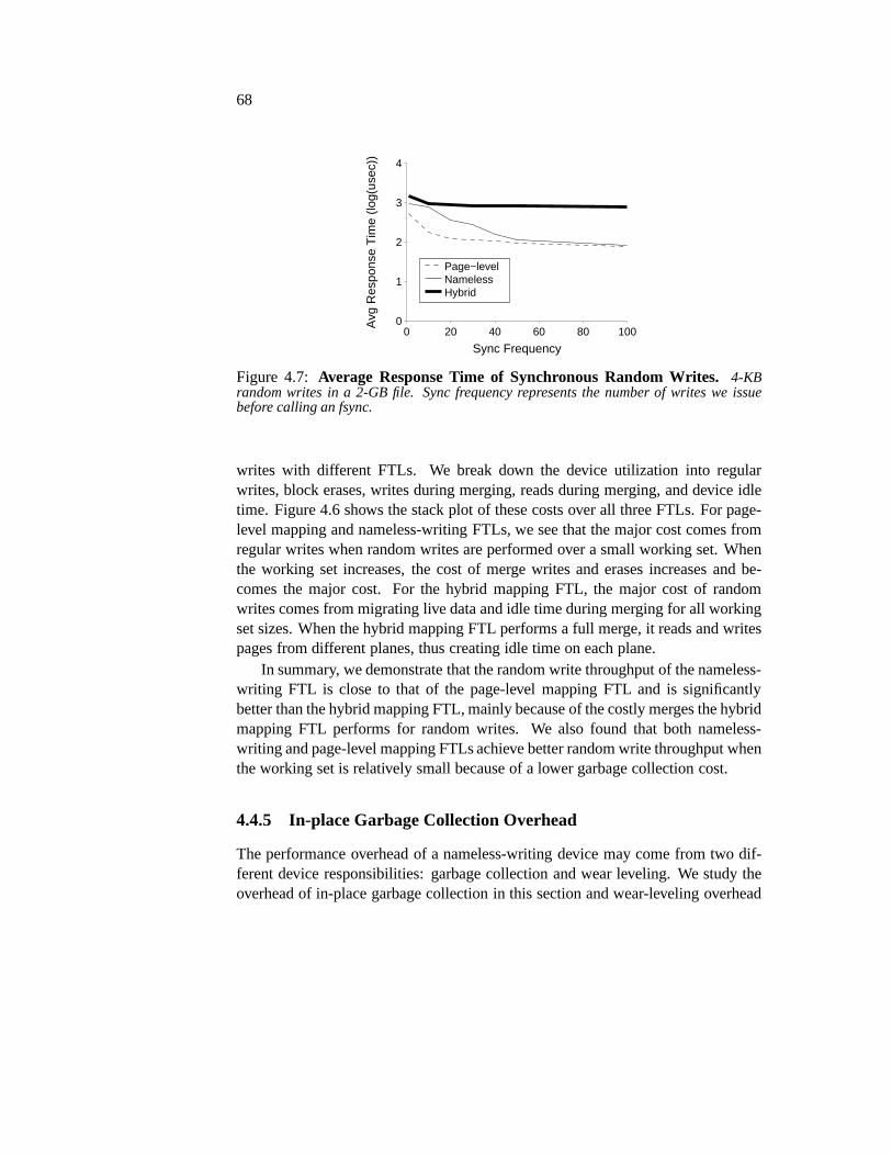
68
Sync Frequency0 20 40 60 80 100
Avg
Res
pons
e T
ime
(log(
usec
))
0
1
2
3
4
Page−levelNamelessHybrid
Figure 4.7: Average Response Time of Synchronous Random Writes.4-KBrandom writes in a 2-GB file. Sync frequency represents the number of writes we issuebefore calling an fsync.
writes with different FTLs. We break down the device utilization into regularwrites, block erases, writes during merging, reads during merging, and device idletime. Figure 4.6 shows the stack plot of these costs over all three FTLs. For page-level mapping and nameless-writing FTLs, we see that the major cost comes fromregular writes when random writes are performed over a smallworking set. Whenthe working set increases, the cost of merge writes and erases increases and be-comes the major cost. For the hybrid mapping FTL, the major cost of randomwrites comes from migrating live data and idle time during merging for all workingset sizes. When the hybrid mapping FTL performs a full merge,it reads and writespages from different planes, thus creating idle time on eachplane.
In summary, we demonstrate that the random write throughputof the nameless-writing FTL is close to that of the page-level mapping FTL andis significantlybetter than the hybrid mapping FTL, mainly because of the costly merges the hybridmapping FTL performs for random writes. We also found that both nameless-writing and page-level mapping FTLs achieve better random write throughput whenthe working set is relatively small because of a lower garbage collection cost.
4.4.5 In-place Garbage Collection Overhead
The performance overhead of a nameless-writing device may come from two dif-ferent device responsibilities: garbage collection and wear leveling. We study theoverhead of in-place garbage collection in this section andwear-leveling overhead

69
Workload1 Workload2
Thr
ough
put (
KIO
PS
)
0
10
20
30
40
Page Nameless
Figure 4.8:Write Throughput with Wear Leveling. Throughput of biased sequen-tial writes with wear leveling under page-level and nameless FTLs.
Metadata RemapTblWorkload1 2.02 MB 321 KBWorkload2 5.09 MB 322 KB
Table 4.4:Wear Leveling Callback Overhead.Amount of additional metadata writesbecause of migration callbacks and maximal remapping tablesize during wear levelingwith the nameless-writing FTL.
in the next section.
Our implementation of the nameless-writing device uses an in-place merge toperform garbage collection. As explained in Section 4.2.2,when there are no wait-ing writes on the device, we may waste the space that has been recently garbagecollected. We use synchronous random writes to study this overhead. We vary thefrequency of callingfsyncto control the amount of waiting writes on the device;when the sync frequency is high, there are fewer waiting writes on the device queue.Figure 4.7 shows the average response time of 4-KB random writes with differentsync frequencies under page-level mapping, nameless-writing, and hybrid mappingFTLs. We find that when sync frequency is high, the nameless-writing device hasa larger overhead compared to page-level mapping. This overhead is due to thelack of waiting writes on the device to fill garbage-collected space. However, wesee that the average response time of the nameless-writing FTL is still lower thanthat of the hybrid mapping FTL, since response time is worse when the hybrid FTLperforms full-merge with synchronous random writes.
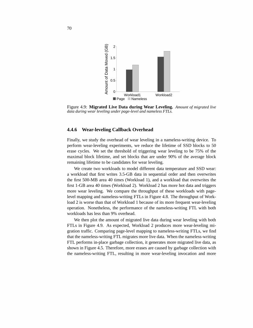
70
Workload1 Workload2Am
ount
of D
ata
Mov
ed (
GB
)
0
0.5
1
1.5
2
Page Nameless
Figure 4.9:Migrated Live Data during Wear Leveling. Amount of migrated livedata during wear leveling under page-level and nameless FTLs.
4.4.6 Wear-leveling Callback Overhead
Finally, we study the overhead of wear leveling in a nameless-writing device. Toperform wear-leveling experiments, we reduce the lifetimeof SSD blocks to 50erase cycles. We set the threshold of triggering wear leveling to be 75% of themaximal block lifetime, and set blocks that are under 90% of the average blockremaining lifetime to be candidates for wear leveling.
We create two workloads to model different data temperatureand SSD wear:a workload that first writes 3.5-GB data in sequential order and then overwritesthe first 500-MB area 40 times (Workload 1), and a workload that overwrites thefirst 1-GB area 40 times (Workload 2). Workload 2 has more hot data and triggersmore wear leveling. We compare the throughput of these workloads with page-level mapping and nameless-writing FTLs in Figure 4.8. The throughput of Work-load 2 is worse than that of Workload 1 because of its more frequent wear-levelingoperation. Nonetheless, the performance of the nameless-writing FTL with bothworkloads has less than 9% overhead.
We then plot the amount of migrated live data during wear leveling with bothFTLs in Figure 4.9. As expected, Workload 2 produces more wear-leveling mi-gration traffic. Comparing page-level mapping to nameless-writing FTLs, we findthat the nameless-writing FTL migrates more live data. Whenthe nameless-writingFTL performs in-place garbage collection, it generates more migrated live data, asshown in Figure 4.5. Therefore, more erases are caused by garbage collection withthe nameless-writing FTL, resulting in more wear-levelinginvocation and more

71
wear-leveling migration traffic.Migrating live nameless data in a nameless-writing device creates callback traf-
fic and additional metadata writes. Wear leveling in a nameless-writing device alsoadds a space overhead when it stores the remapping table for migrated data. Weshow the amount of additional metadata writes and the maximal size of the remap-ping table of a nameless-writing device in Figure 4.4. We findboth overheads tobe low with the nameless-writing device: an addition of lessthan 6 MB metadatawrites and a space cost of less than 350 KB.
In summary, we find that both the garbage-collection and wear-leveling over-heads caused by nameless writes are low. Since wear levelingis not a frequentoperation and is often scheduled in system idle periods, we expect both perfor-mance and space overheads of a nameless-writing device to beeven lower in realsystems.
4.4.7 Reliability
To determine the correctness of our reliability solution, we inject crashes in thefollowing points: 1) after writing a data block and its metadata block, 2) afterwriting a data block and before updating its metadata block,3) after writing a datablock and updating its metadata block but before committingthe metadata block,and 4) after the device migrates a data block because of wear leveling and before thefile system processes the migration callback. In all cases, we successfully recoverthe system to a consistent state that correctly reflects all written data blocks andtheir metadata.
Our results also show that the overhead of our crash recoveryprocess is rel-atively small: from 0.4 to 6 seconds, depending on the amountof inconsistentmetadata after crash. With more inconsistent metadata, theoverhead of recovery ishigher.
4.5 Summary
In this chapter, we introduced nameless writes, a new write interface built to reducethe inherent costs of indirection. With nameless writes, the file system does notperform allocation and sends only data and no logical address to the device. Thedevice then sends back the physical address, which is storedin the file systemmetadata.
In implementing nameless writes, we met a few challanges, such as the recur-sive update problem and the device block migration problem.We solve these prob-

72
lems by introducing address space separation (logical and physical address space)and new types of interface (migration callback). Through the implementation ofnameless writes on the Linux ext3 file system and an emulated nameless-writingdevice, we demonstrated how to port a file system to use nameless writes.
Through extensive evaluations, we found that nameless writes largely reducethe mapping table space cost as compare to the page-level mapping and the hybridmapping FTLs. We also found that for random writes, namelesswrites largelyoutperforms the hybrid mapping FTL and matchs the page-level mapping FTL.Overall, we show the great advantage of nameless writes fromboth worlds: thegood performance like the page-level mapping FTL and the small mapping tablespace that is even less than the hybrid mapping FTL.

73
Chapter 5
Hardware Experience ofNameless Writes
As with most research work of flash memory, we evaluated our nameless writesdesign not with real hardware but with our own SSD emulator. Simulators andemulators are convenient and flexible to build and use. However, simulation andemulation have their limitations.
The nameless writes design makes substantial changes to theI/O interface, theSSD FTL, and the file system. Our SSD emulator lies directly below the file sys-tem and talks to it using software function calls, and thus simplifies the systemwhich the nameless writes design is supposed to change. Because of the changesrequired by nameless writes at different storage layers, nameless writes are an idealchoice for studying the differences between real hardware systems and simula-tion/emulation, as well as the challenges in building a new storage interface for realstorage systems.
Therefore, we decided to build a hardware prototype of nameless writes and useit to validate our nameless writes design. In this chapter, we discuss our hardwareexperience with implementing nameless writes with the OpenSSD Jasmine hard-ware platform [86], the challenges of building nameless writes with real hardware,and our solutions to them [79].
Our evaluation results of the nameless writes hardware prototype agrees withthe conclusions we made in Chapter 4: nameless writes largely remove the excessindirection in SSDs and its space and performance costs.
The rest of this chapter is organized as follows. We first describe the architec-ture of the hardware board we use in Section 5.1. We then discuss the challengesof porting nameless writes to hardware in Section 5.2. We present our solutions to

74
Figure 5.1:OpenSSD ArchitectureThe major components of OpenSSD platform arethe Indilinx Barefoot SSD controller; internal SRAM, SDRAM, and NAND flash; special-ized hardware for buffer management, flash control, and memory utility functions; anddebugging UART/JTAG ports.
these challenges and the implementation of the nameless writes hardware prototypein Section 5.3. In Section 5.4, we evaluate the nameless writes hardware prototype.Finally, we summarize this chapter in Section 5.5.
5.1 Hardware Platform
We use the OpenSSD platform [86] (Figure 5.1) as it is the mostup-to-date openplatform available today for prototyping new SSD designs. It uses a commercialflash controller for managing flash at speeds close to commodity SSDs. We proto-type a nameless-writing SSD to verify its practicality and validate if it performs aswe projected in emulation earlier.
5.1.1 OpenSSD Research Platform
The OpenSSD board is designed as a platform for implementingand evaluatingSSD firmware and is sponsored primarily by Indilinx, an SSD-controller manufac-turer [86]. The board is composed of commodity SSD parts: an Indilinx BarefootARM-based SATA controller, introduced in 2009 for second generation SSDs and

75
Controller ARM7TDMI-S Frequency 87.5 MHzSDRAM 64 MB (4 B ECC/128 B) Frequency 175 MHzFlash 256 GB Overprovisioning 7%Type MLC async mode Packages 4Dies/package 2 Banks/package 4Channel Width 2 bytes Ways 2Physical Page 8 KB (448 B spare) Physical Block 2 MBVirtual Page 32 KB Virtual Block 4 MB
Table 5.1: OpenSSD device configuration. This table summarizes the hardwareconfiguration in the OpenSSD platform.
still used in many commercial SSDs; 96 KB SRAM; 64 MB DRAM for storing theflash translation mapping and for SATA buffers; and 8 slots holding up to 256 GBof MLC NAND flash. The controller runs firmware that can send read/write/eraseand copyback (copy data within a bank) operations to the flashbanks over a 16-bitI/O channel. The chips use two planes and have 8 KB physical pages. The deviceuses large 32 KB virtual pages, which improve performance bystriping data acrossphysical pages on two planes on two chips within a flash bank. Erase blocks are4 MB and composed of 128 contiguous virtual pages.
The controller provides hardware support to accelerate command processing inthe form of command queues and a buffer manager. The command queues pro-vide a FIFO for incoming requests to decouple FTL operationsfrom receivingSATA requests. The hardware provides separate read and write command queues,into which arriving commands can be placed. The queue provides afast pathforperformance-sensitive commands. Less common commands, such asATA flush,idle andstandbyare executed on aslow paththat waits for all queued commandsto complete. The device transfers data from the host using a separate DMA con-troller, which copies data between host and device DRAM through a hardwareSATA buffer manager (a circular FIFO buffer space).
The device firmware logically consists of three components as shown in Fig-ure 5.2: host interface logic, the FTL, and flash interface logic. The host inter-face logic decodes incoming commands and either enqueues them in the commandqueues (for reads and writes), or stalls waiting for queued commands to complete.The FTL implements the logic for processing requests, and invokes the flash in-terface to actually read, write, copy, or erase flash data. The OpenSSD platformcomes with open-source firmware libraries for accessing thehardware and threesample FTLs. We use the page-mapped GreedyFTL as our baseline; it uses log

76
Figure 5.2:OpenSSD Internals. Major components of OpenSSD internal design arehost interface logic, flash interface logic, and flash translation layer.
structured allocation and thus has good random write performance. It is similar tothe page-level mapping FTL we used in our emulation in Chapter 4.
5.2 Challenges
Before delving into the implementation details of the nameless writes design withthe OpenSSD platform and the SATA interface, we first discussthe challenges weencountered in integrating nameless writes with real hardware and a real hardwareinterface.
Nameless writes present unique implementation challengesbecause they changethe interface between the host OS and the storage device by adding new commands,new command responses, and unrequested up-calls. Table 4.1in Chapter 4 lists thenameless writes interfaces.
When moving from emulation (Chapter 3) to real hardware, notonly the hard-ware SSD needs to be ported to nameless writes, but the hardware interface and theOS stack do as well. Figure 5.2 describes how our SSD emulatorand the real SSDwork with the OS.
The emulator sits at the OS block layer and interacts with theOS through soft-ware interfaces. I/Os are passed between the file system and the emulator using thebio structure. Adding new types of interfaces is easy. For example, the nameless

77
Figure 5.3:Architecture of OS Stack with Emulated and Real SSD.This graphillustrates the OS stack above a real SSD with SATA interface. As opposed to the stack tothe real device, the emulator is implemented directly belowthe file system.
write command is implemented by adding a command type flag in the bio structure;the physical address returned by a nameless write is implemented by reusing thelogical block address field of the bio structure, which is then interpreted speciallyby a file system that works with nameless writes. Adding the migration callback isalso relatively easy: the device emulator calls a kernel function, which then uses akernel work queue to process the callback requests.
The interaction between the OS and the real hardware device is much moreinvolved than with the emulator. I/O requests enter the storage stack from the filesystem and go through a scheduler and then the SCSI and ATA layers before theAHCI driver finally submits them to the device. To implement our hardware pro-totype, we have to integrate the nameless writes interface into this existing storagearchitecture. Implementing a new interface implies the need to change the filesystem and the OS stack, the ATA interface, and the hardware SSD. The biggestchallenge in this process is that some part of the storage stack is fixed in the hard-

78
ware and cannot be accessed or changed. For example, most of the ATA interface isimplemented in the hardware ports and cannot be changed (seeChapter 2 for moredetails). Certain parts of the OpenSSD platform cannot be changed or accessedeither, such as the OOB area.
5.2.1 Major Problems
We identified four major problems while implementing nameless writes with thereal hardware system: how to get new commands through the OS storage stack intothe device, how to get new responses back from the device, howto have upcallsfrom the device into the OS, and how to implement commands within the devicegiven its hardware limitations.
First, the forward commands from the OS to the device pass through severallayers in the OS, shown in Figure 5.2, which interpret and acton each commanddifferently. For example, the I/O scheduler can merge requests to adjacent blocks.If it is not aware that thevirtual-write andnameless-writecommands are different,it may incorrectly merge them into a single, larger request.Thus, the I/O schedulerlayer must be aware of each distinct command.
Second, the reverse-path responses from the device to the OSare difficult tochange. The nameless writes interface returns the physicaladdress for data fol-lowing a nameless write. However, the SATA write command normal response hasno fields in which an address can be returned. While, the errorresponse allowsan address to be returned, both the AHCI driver and the ATA layer interpret errorresponses as a sign of data loss or corruption. Their error handlers retry the readoperation again with the goal of retrieving the page, and then freeze the device byresetting the ATA link. Past research demonstrated that storage systems often retryfailed requests automatically [39, 76].
Third, there are no ATA commands that are initiated by the device. Namelesswrites require upcalls from the device to the OS for migration callbacks. Imple-menting upcalls is challenging, since all ATA commands are initiated by the OS tothe device.
Finally, the OpenSSD platform provides hardware support for the SATA proto-col (see Figure 5.2) in the form of hardware command queues and a SATA buffermanager. When using the command queues, the hardware does not store the com-mand itself and identifies the command type from the queue it is in. While firmwarecan choose where and what to enqueue, it can only enqueue two fields: the logicalblock address (lba) and request length (numsegments). Furthermore, there are onlytwo queues (read and write), so only two commands can executeas fast commands.

79
5.3 Implementation Experiences
In this section, we discuss how we solve the challenges of transferring the namelesswrites design from emulation to real hardware and our experience with implement-ing nameless writes on the OpenSSD hardware with the Linux kernel and the SATAinterface. We focus our discussion on changes in the layers below the file system,since the file system changes are the same for the emulator andthe real hardware.
5.3.1 Adding New Command Types
To add a new command type, we change the OS stack, the ATA interface, andthe OpenSSD firmware. We now discuss the techniques we used for introducingnew command types. We also discuss the implementation of newnameless writescommands that do not involve return field changes or upcalls,both of which weleave for later sections in this chapter.Forward commands through the OS: At the block-interface layer, we seek toleave as much code unmodified as possible. Thus, we augment block requests withan additional command field, effectively adding our new commands as sub-typesof existing commands. The nameless write, the nameless overwrite, and the virtualwrite commands are encoded using three special sub-types with the normal writecommand. We also use the normal write command to encode the trim command.The trim command, however, does not send any data but only block addresses tothe device. The virtual and physical read commands are encoded in a similar waywith normal read commands.
We modified the I/O scheduler to only merge requests with the same commandand sub-type. The SCSI and ATA layers then blindly pass the sub-type field downto the next layer. We also modified the AHCI driver to communicate commandsto the OpenSSD device. As with higher levels, we use the approach of adding asub-type to existing commands.ATA interface: Requests use normal SATA commands and pass the new requesttype in thersv1reserved field, which is set to zero by default.OpenSSD request handling: Within the device, commands arrive from the SATAbus and are then enqueued by the host-interface firmware. TheFTL asynchronouslypulls requests from the queues to be processed. Thus, the keychange needed fornew requests is to communicate the command type from arriving commands tothe FTL, which executes commands. We borrow two bits from thelength field ofthe request (a 32-bit value) to encode the command type. The FTL decodes theselength bits to determine which command to execute, and invokes the function forthe command. This encoding ensures that the OpenSSD hardware uses the fast

80
path for new variations of reads and writes, and allows multiple variations of thecommands.
5.3.2 Adding New Command Return Field
Nameless writes pass data but no address, and expect the device to return a physicaladdress or an error indicating that the write failed. Passing data without an addressis simple, as the firmware can simply ignore the address. However, a write replymessage only contains 8 status bits; all other fields are reserved and can not be usedto send physical addresses through the ATA interface.
Our first attempt was to alter the error return of an ATA write to return physicaladdresses for nameless writes. On an error return, the device can supply the addressof the block in the request that could not be written. This seemed promising as away to return the physical address. However, the device, theAHCI driver, and theATA layer interpret errors as catastrophic and thus we couldnot use errors to returnthe physical address.
Our second attempt was to re-purpose an existing SATA command thatalreadyreturns a 64-bit address. Only one command in the ATA protocol,READNATIVEMAX ADDR, returns an address. The OS would first sendREADNATIVEMAX ADDR, to which the nameless-writing device returns the nextavailable physical address. The OS would then record the physical address and sendthe nameless write command with that address.
We found that using two commands for a write raised new problems. First, theREADNATIVEMAX ADDR command is an unqueuable command in the SATAinterface, so both the ATA layer and the device will flush queued commands andhurt performance. Second, the OS may reorder nameless writes differently than theREADNATIVEMAX ADDRcommands, which can hurt performance at the deviceby turning sequential writes into random writes. Worse, though, is that the OS maysend multiple independent writes that lie on the same flash virtual page. Becausethe granularity of file-system blocks (4 KB) is different from internal flash virtualpages (32 KB), the device may try to write the virtual page twice without erasingthe bock. The second write silently corrupts the virtual page’s data.
Therefore, neither of these two attempts to integrate a physical address in thewrite return path with the ATA interface succeeded. We deferthe discussion of ourfinal solution to Section 5.3.4.
81
5.3.3 Adding Upcalls
Themigration-callbackcommand raised additional problems. Unlikeall existingcalls in the SATA interface, a nameless-writing device can generate this up-callasynchronously during background tasks such as wear leveling and garbage collec-tion. This call notifies the file system that a block has been relocated and it shouldupdate metadata to reflect the new location.
To implement migration callbacks, we first considered piggybacking the upcallson responses to other commands, but this raises the same problem of returningaddresses described above. Alternatively, the file system could periodically poll formoved data, but this method is too costly in performance given the expected rarityof up-calls. We discuss our final solution in the next section.
5.3.4 Split-FTL Solution
Based on the complexity of implementing the full nameless writes interface withinthe device, we opted instead to implement asplit-FTL design, where the responsi-bilities of the FTL are divided between firmware within the device and an FTL layerwithin the host operating system. This approach has been used for PCI-attachedflash devices [33], and we extend it to SATA devices as well. Inthis design, thedevice exports a low-level interface and the majority of FTLfunctionality residesas a layer within the host OS.
We built the nameless-writing FTL at the block layer below the file system andthe I/O scheduler and above the SCSI, ATA, and AHCI layers. Figure 5.4 showsthe design. The FTL in the host OS implements the full set of interfaces listedin Table 4.1 in Chapter 4; the device implements a basic firmware that providesflash-page read, flash-page write, andflash-block erase. The host FTL converts acommand in the nameless-write interface into a sequence of low-level flash opera-tions.
We built the nameless-write FTL below the I/O scheduler, since placing theFTL above the I/O scheduler creates problems when allocating physical addresses.If the FTL performs its address allocation before requests go into the I/O scheduler,the I/O scheduler may re-order or merge requests. If the FTL assigns multiplephysical addresses from one virtual flash page, the scheduler may not coalesce thewrites into a single page-sized write. The device may see multiple writes (withdifferent physical addresses) to the same virtual flash pagewithout erases and thusresult in data corruption.
The nameless-writing FTL processes I/O request queues before they are sent tothe lower layers. For each write request queue, the FTL finds anew flash virtual

82
Figure 5.4:Nameless Writes Split-FTL Architecture. This figure depicts the archi-tecture of the split-FTL design of nameless writes. Most of the nameless writes functionalityis implemented as a layer within the host operating system (below the file system and theblock layer). The nameless writes interfaces are implemented between the nameless-writingFTL and the block layer. The device (OpenSSD) operates as a raw flash device.
page and assigns physical addresses in the virtual page to the I/Os in the requestqueue in a sequential order. We change the I/O scheduler to allow a request queue tobe at most the size of the flash virtual page (32 KB with OpenSSD); going beyondthe virtual page size does not improve write performance butcomplicates FTLimplementation. We choose not to use the same flash virtual page across differentwrite request queues, since doing so will lead to data corruption; lower layers mayreorder request queues, resulting in the device write the same virtual page withouterasing it. The write performance is highly dependent on thesize of the requestqueues, since each request queue is assigned a flash virtual page; larger request

83
queues result in more sequential writes at the device level.Therefore, to improverandom write performance, we change the kernel I/O scheduler to merge any writes(virtual or physical) to the nameless-writing SSD device. We treat virtual writes ina similar way as physical writes. The only difference is thatwhen we assign aphysical address to a virtual write, we keep the address mapping in the FTL.
For read requests, we disallow merging of physical and virtual reads and do notchange other aspects of the I/O scheduler. For virtual reads, we look up the addressmapping in the FTL.
The FTL in the host OS maintains all metadata that were originally main-tained by the device firmware, including valid pages, the free block list, block erasecounts, and the bad block list. On aflush, used byfsync(), the FTL writes all themetadata to the device and records the location of the metadata at a fixed location.
The FTL uses the valid page information to decide which blockto garbage col-lect. It reads the valid pages into host DRAM, erases the block, and then writes thedata to a new physical block. Once the data has been moved, it sends amigration-callbackto notify the file system that data has been moved. Because theFTL is inthe host OS, this is a simple function call.
Running the FTL in the kernel provides a hospitable development environment,as it has full access to kernel services. However, it may be more difficult to opti-mize the performance of the resulting system, as the kernel-side FTL cannot takeadvantage of internal flash operations, such as copy-backs to efficiently move datawithin the device. For enterprise class PCI-e devices, kernel-side FTLs followingNVM-express specification can implement the block interface directly [72] or usenew communication channels based on RPC-like mechanisms [65].
5.3.5 Lessons Learned
The implementation of nameless writes with OpenSSD and the ATA interfaces im-parted several valuable lessons.
• The OS storage stack’s layered design may require each layerto act differ-ently for the introduction of a new forward command. For example, newcommands must have well-defined semantics for request schedulers, such aswhich commands can be combined and how they can be reordered.
• The device response paths in the OS are difficult to change. Therefore, de-signs that radically extend existing communication from the device shouldconsider the data that will be communicated.

84
• Upcalls from the device to the OS do not fit the existing communicationchannels between the host and the device, and changing the control path forreturning values is significantly more difficult than introducing new forwardcommands. Thus, it may be worthwhile to consider new reversecommu-nication channels based on RPC-like mechanisms [65] to implement blockinterface for PCI-e devices following the NVM-express specification [72].
• Building the nameless-writing FTL below the block layer is simpler than atthe device firmware since the block layer has simpler interfaces and interactswith the file system directly.
• Allowing the host OS to write directly to physical addressesis dangerous,because it cannot guarantee correctness properties such asensuring the era-sure of a flash page before it is written. This is particularlydangerous if theinternal write granularity is different than the granularity used by the OS.
• With the knowledge of SSD hardware configuration, the kernelI/O schedulercan be changed to improve I/O performance with an in-kernel FTL.
5.4 Evaluation
Our overall goal of implementing nameless writes in a hardware prototype is tovalidate our design choices. We evaluate the memory space and performance ofnameless writes prototype with the split-FTL design.
We evaluate the nameless writes prototype to validate the performance claimsof the interface and memory consumption as projected earlier in Section 4.4. Wecompare the nameless writes prototype against the OpenSSD baseline page-mappedFTL. We measure performance withfio microbenchmarks and memory consump-tion with different file system images. We execute the experiments on an OpenSSDboard with two flash chips (8 flash banks with 64 GB total).
Figure 5.5 shows the random (4 KB blocks) and sequential write and read per-formance with the baseline OpenSSD FTL and nameless writes.For sequentialwrites, sequential reads, and random reads, the nameless-writing FTL has similarIOPS as the baseline page-mapped FTL. It assigns physical addresses in sequentialorder, which is the same as the baseline FTL. For random writes, nameless writesperform better than the baseline but worse than sequential write of either FTL. Eventhough we change the I/O scheduler to merge random writes, wefind the randomwrite request queue size is smaller than the size of the flash virtual page.
Table 5.2 presents the memory usage of the page-mapped FTL and the nameless-writing FTL with different file system image sizes (from 4 GB to 48 GB), which

85
I/O O
pera
tions
per
sec
ond
0
5000
10000
15000
SW RW SR RRBaseline NamelessWrites
Figure 5.5: Read and Write Performance. This figure presents the IOPS of theOpenSSD FTL and the nameless writes split-FTL for fio benchmarks (sequential and ran-dom reads and writes with a 4 KB request size).
File System SizeFTL 4 GB 8 GB 16 GB 32 GB 48 GBPage-Map 2.50 MB 9.10 MB 17.8 MB 35.1 MB 52.8 MBNameless 94 KB 189 KB 325 KB 568 KB 803 KB
Table 5.2:FTL Memory Consumption. This table presents the memory usage ofthe baseline page-level mapping FTL and the nameless-writing FTL. We use Impressionsto generate typical file system images with different sizes.
we created using Impressions [4]. The memory consumption includes the addressmapping tables and all additional FTL metadata. The nameless-writing FTL usesmuch less memory than the page-mapped FTL. Unlike the page-mapped FTL, thenameless-writing FTL does not need to store the address mappings for namelesswrites (data) and only stores address mappings for virtual writes (metadata).
Overall, we find that the core nameless writes design performs similarly to thepage-mapped FTL and provides significant memory savings as projected earlier inChapter 4.
5.5 Summary
In this chapter, we described our experience with building nameless writes with theOpenSSD hardware board, the challenges in moving nameless writes to hardware,and our solutions to them.
The biggest challenges we met in our hardware experience arechanging the I/O

86
return path and adding upcalls from the device, neither of which we foresaw whenwe built nameless writes with emulation.
Because of the restrictions of ATA interface, we change the nameless writesdesign to use two split parts, an FTL at the OS block layer thatmanages most of theresponsibilities of a nameless-writing device, and a simple raw FTL that managesa raw SSD device. We show through evaluation that this designworks well with areal hardware system, and achieves the same benefits of de-indirection as with ouroriginal nameless writes design using emulation.
Overall, we found our hardware experience to be rewarding; we learned a set ofnew lessons in how hardware and real systems can be differentfrom simulation andemulation. Even because of a single restriction in real hardware, the whole systemmay need to be re-designed.

87
Chapter 6
A File System De-Virtualizer
We demonstrated in Chapters 4 and 5 that nameless writes are able to largely re-move SSD indirection and its space and performance costs. However, the namelesswrites solution has a few drawbacks. First, nameless writesrequire fundamentalchanges to the file system, the OS, the device, and the device interface. Second,the nameless-write approach creates unnecessary overheadbecause it performs de-indirection for all data writes; instead, de-indirection can be performed at deviceidle time to hide its overhead.
To overcome the drawbacks of nameless writes, we propose theFile System De-Virtualizer (FSDV), a mechanism to dynamically remove the indirection in flash-based SSDs with small changes to existing systems. FSDV is a user-level tool thatwalks through file system structures and changes file system pointers to physicaladdresses; when pointers arede-virtualized, the logical to physical address map-pings in the SSD can be removed. FSDV can be invoked periodically, when thememory pressure in SSD is high, or when the device is idle.
We implemented a prototype of FSDV and modified the ext3 file system and ouremulated flash-based SSD for it. Our evaluation results of FSDV demonstrate thatFSDV largely reduces device mapping table space in a dynamicway. It achievesthis goal with small performance overhead on foreground I/Os.
The rest of this chapter is organized as follows. We present the basic design ofFSDV in Section 6.1. We then describe our implementation of the FSDV tool, thechanges to the ext3 file system, and our SSD emulator for FSDV in Section 6.2. InSection 6.3, we present our evaluation results of FSDV. Finally, we summarize thischapter in Section 6.4.
88
6.1 System Design
In this section, we present the overall design of FSDV, and how it interacts with thedevice and the file system that support FSDV. We design FSDV with the followinggoals in mind.
1. Indirection mappings can be (largely) removed in a dynamic way. Doing soallows FSDV to be able to remove the device virtualization maintained eitherinside the device hardware or in the host software.
2. The performance overhead of FSDV should be low, so that there will benegligible impact on normal I/Os.
3. There should only be small changes in file systems, OSes, device firmware,and device I/O interfaces. Doing so will allow for an easy integration ofFSDV into existing systems.
FSDV is a user-level tool that runs periodically or when needed to remove theexcess virtualization of a virtualized storage device. When FSDV is not running,a normal file system runs with the storage device in a largely unmodified way.The file system performs block allocation in thelogical address space. The deviceallocatesdevice addressesand maintains an indirection mapping from logical todevice addresses. When the mapping table space pressure is high, FSDV can beinvoked to perform de-virtualization to remove indirection mappings. FSDV canalso be invoked periodically or when the device is idle.
6.1.1 New Address Space
FSDV de-virtualizes a block by changing the file system pointer that points to it(i.e., the metadata) to use the device address. After FSDV de-virtualizes a block,it is moved from the logical address space to thephysical addressspace and di-rectly represents a device address (i.e., no mapping is maintained for the block).As workloads perform new I/Os, the file system allocates new data in the logicaladdress space and overwrites existing data in the physical address space. For theformer, the device adds a mapping from the logical address tothe device address.For the latter, the device adds a mapping from the old physical address to the newdevice address.
Figure 6.1 gives an example of FSDV address spaces and indirection mappings.Since a block can be in different address spaces, we need a method to distinguishlogical addresses from physical ones. We discuss our methodin Section 6.2.
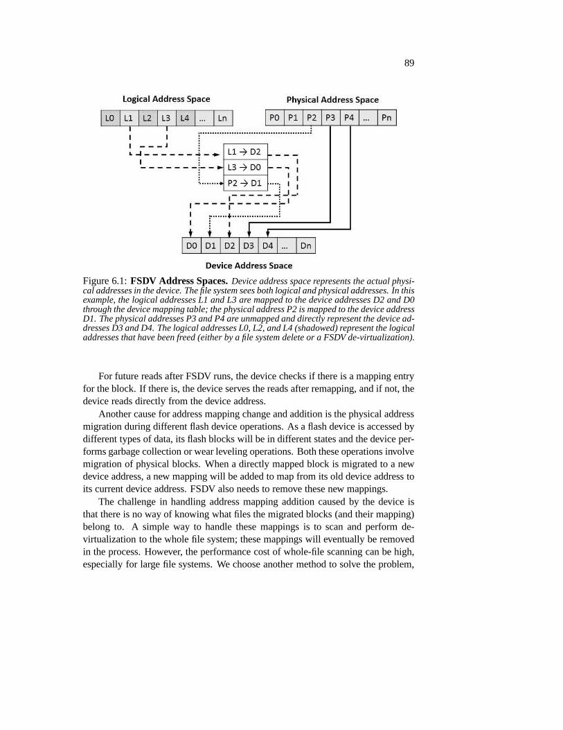
89
Figure 6.1:FSDV Address Spaces.Device address space represents the actual physi-cal addresses in the device. The file system sees both logicaland physical addresses. In thisexample, the logical addresses L1 and L3 are mapped to the device addresses D2 and D0through the device mapping table; the physical address P2 ismapped to the device addressD1. The physical addresses P3 and P4 are unmapped and directly represent the device ad-dresses D3 and D4. The logical addresses L0, L2, and L4 (shadowed) represent the logicaladdresses that have been freed (either by a file system deleteor a FSDV de-virtualization).
For future reads after FSDV runs, the device checks if there is a mapping entryfor the block. If there is, the device serves the reads after remapping, and if not, thedevice reads directly from the device address.
Another cause for address mapping change and addition is thephysical addressmigration during different flash device operations. As a flash device is accessed bydifferent types of data, its flash blocks will be in differentstates and the device per-forms garbage collection or wear leveling operations. Boththese operations involvemigration of physical blocks. When a directly mapped block is migrated to a newdevice address, a new mapping will be added to map from its olddevice address toits current device address. FSDV also needs to remove these new mappings.
The challenge in handling address mapping addition caused by the device isthat there is no way of knowing what files the migrated blocks (and their mapping)belong to. A simple way to handle these mappings is to scan andperform de-virtualization to the whole file system; these mappings willeventually be removedin the process. However, the performance cost of whole-file scanning can be high,especially for large file systems. We choose another method to solve the problem,

90
involving associating each block to the file to which it belongs. Specifically, wechange the file system write interface to also include the inode number and let thedevice store it with the block. When the device migrates a block and adds a newmapping, it records the inode number the block belongs to; FSDV will processthese files in its later run.
6.1.2 FSDV Modes
FSDV can run offline (with unmounted file system) or online (with mounted filesystem). The offline FSDV works with an unmounted file system.After the filesystem has been unmounted (either by user or forcefully by FSDV), FSDV goesthrough the file system data structures and processes file system metadata to de-virtualize file system pointers. The de-virtualized file system is then mounted.
The offline FSDV provides a simple and clean way to perform filesystemde-virtualization. However, it requires file systems to be unmounted before it canstart processing and is not suitable for most storage systems. Thus, we also designan online version of FSDV which runs while the file system is mounted and fore-ground I/Os run in a (largely) unaffected fashion. The majordifference betweenthe online FSDV and the offline one is that it needs to make surethat it does notleave any inconsistency in page cache or for ongoing I/Os. FSDV interacts with thefile system through the FSDV-supporting device to isolate the blocks it processesfrom the file system.
6.2 Implementation
In this section, we discuss our implementation of the FSDV tool, the offline and theonline version of it. To support FSDV, changes in device firmwares, file systems,and OSes are needed. We also discuss these changes in this section.
6.2.1 File System De-virtualizer
We now describe our implementation of the offline and the online FSDV and a fewoptimizations we make for better FSDV performance.
Offline File System De-Virtualizer
The offline FSDV works with unmounted file systems. As explained in Section 2.2.1,for most file systems like ext2, ext3, and ext4, a file can be viewed as a tree structurewith the inode of the file at the tree root, indirect blocks (orextent blocks) in the
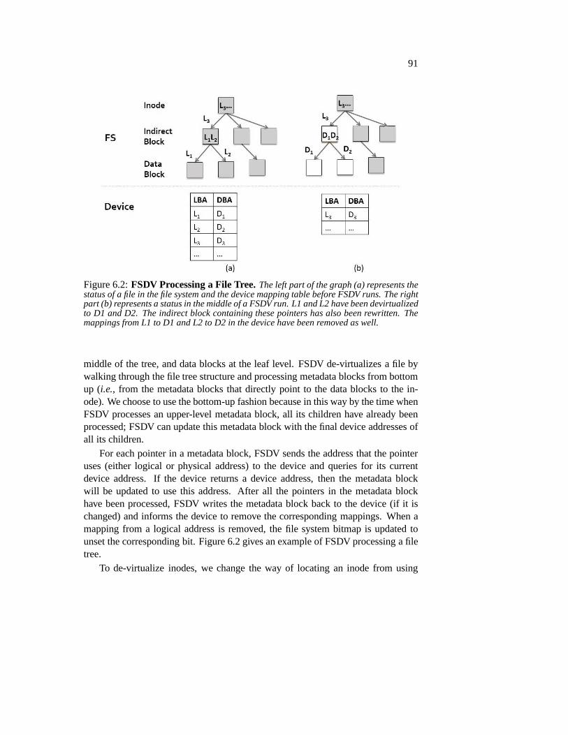
91
Figure 6.2:FSDV Processing a File Tree.The left part of the graph (a) represents thestatus of a file in the file system and the device mapping table before FSDV runs. The rightpart (b) represents a status in the middle of a FSDV run. L1 andL2 have been devirtualizedto D1 and D2. The indirect block containing these pointers has also been rewritten. Themappings from L1 to D1 and L2 to D2 in the device have been removed as well.
middle of the tree, and data blocks at the leaf level. FSDV de-virtualizes a file bywalking through the file tree structure and processing metadata blocks from bottomup (i.e., from the metadata blocks that directly point to the data blocks to the in-ode). We choose to use the bottom-up fashion because in this way by the time whenFSDV processes an upper-level metadata block, all its children have already beenprocessed; FSDV can update this metadata block with the finaldevice addresses ofall its children.
For each pointer in a metadata block, FSDV sends the address that the pointeruses (either logical or physical address) to the device and queries for its currentdevice address. If the device returns a device address, thenthe metadata blockwill be updated to use this address. After all the pointers inthe metadata blockhave been processed, FSDV writes the metadata block back to the device (if it ischanged) and informs the device to remove the correspondingmappings. When amapping from a logical address is removed, the file system bitmap is updated tounset the corresponding bit. Figure 6.2 gives an example of FSDV processing a filetree.
To de-virtualize inodes, we change the way of locating an inode from using

92
the inode number to using the device address of the inode block and the offset ofthe inode within the inode block. After FSDV de-virtualizesall per-file metadatablocks as described above, FSDV starts to process inodes andthe metadata blockspointing to them (i.e., directory blocks). FSDV changes the pointer pointing to aninode to use the device address of the inode block and the inode’s offset withinit. If the inode is de-virtualized from an inode number (its original form), thefile system inode bitmap will also be updated. Currently, we do not de-virtualizedirectory inodes, since processing directory data structures is more complicatedand directories only account for a small part of typical file systems [5]; we leavede-virtualizing directory inodes for future work.
Finally, we do not need to deal with any metadata in file systemjournals. Whenunmounted, a file system’s journal is checkpointed. Thus, there are no outstandingtransactions and the journal is empty. We do not de-virtualize block group bitmapblocks, group description blocks, or superblocks either, since they only account fora small space in the file system.
Online De-Virtualizer
The online FSDV runs while the file system is mounted. Most of its mechanismsare the same as the offline FSDV. However, since we allow foreground I/Os to beperformed while the online FSDV is running, we need to make sure that such asituation does not leave the file system inconsistent. To achieve this goal, FSDVinforms the file system (through the device) about the blocksit wants to isolate; thefile system then flushes all the page caches corresponding to these blocks. WhenFSDV is processing these blocks, the device will prevent ongoing I/Os to themsimply by stalling the I/Os until FSDV finishes its processing. The FSDV processregisters a special process ID with the device, so that I/Os issued by FSDV willnever be blocked.
We have two options in terms of blocking granularity for the online FSDV: ateach file and at each metadata block. If we choose blocking at the file granularity,the device sends the inode identity to the file system, which then flushes all pagecaches belonging to this file. The device keeps track of the inode that FSDV isprocessing and stalls all file system I/Os with this inode until FSDV finishes pro-cessing it. The per-file method is conceptually simple and fits well with the wayFSDV performs de-virtualization: one file at a time. However, it creates a higherperformance overhead, especially for big files, since all blocks belonging to a fileare flushed from the page cache and all I/Os of the file are stalled when FSDV isprocessing the file.
If we choose blocking at the metadata block level, FSDV sendsall the block
93
numbers which the metadata block points to and the metadata block number it-self to the file system (again, through the device). The file system then flushesthe corresponding blocks from the page cache. The device keeps track of theseblock addresses and prevent I/Os to them until FSDV finishes its processing of themetadata block.
Optimization Policies
We introduce a couple of optimizations to reduce the overhead of FSDV. First,since FSDV runs periodically, it does not need to process thefiles that have notbeen changed (overwritten or appended) since the last run ofFSDV. We change thefile system to record the updated files (particularly, inodes) and to send the list ofsuch inodes to the device during journal commit. Notice thatwe do not need toworry about the consistency of such updated inode list; evenif they are wrong, thefile system will still be consistent, since FSDV will just process unnecessary (i.e.,unchanged) files.
To further reduce the run time of FSDV, we can choose not to process hot datawith FSDV, since they will soon be overwritten after FSDV de-virtualizes them.The file system sends the update time of the inodes together with the changed inodelist to the device. FSDV uses ahot inode thresholdto only process files that are notaccessed recently. For example, if we set the hot inode threshold to be 1/10 of thetime window between two FSDV runs, the latter run will ignorethe inodes that areupdated within 1/10 of such time window.
6.2.2 Device Support
We have changed our SSD emulator (described in Chapter 3) to support FSDV.Most part of the emulated SSD and its FTL are not changed. The device stillperforms device address allocation for writes. We choose touse log-structuredallocation and page-level mapping for better performance.For reads, the devicelooks up its mapping table and either read it directly from the device address orread the device address after mapping. For a write, the device records the inodenumber associated with the write in the OOB area adjacent to the data page that thedevice assigns the write to. When the device migrates a data page during a garbagecollection or wear leveling operation, it also moves the inode number to the newOOB area. If a mapping is added because of this migration, thedevice also recordsthe inode number for FSDV to process in its next round.
FSDV interacts with the FSDV-supporting device using normal I/O operationsand simple ioctl commands. Table 6.1 summarizes the interfaces between FSDV

94
and the device. When FSDV queries the device for the device address of a block,the device looks up its mapping and returns the mapped address or the no-mapping-found state to FSDV. After processing and writing new metadata block, FSDV tellsthe device to remove corresponding mappings.
For performance optimization of FSDV, the device also records the files (theirinode identities) that have been updated from the last run ofFSDV (from the newinode list that the file system sends to the device). FSDV reads and processes thesenew files. When FSDV finishes all its processing, the device deletes all the recordednew inodes. We choose to only store the new file record in device RAM and notpermanently on flash memory, since even if the new file record is lost or is wrong,it will not affect the consistency or correctness of the file system (but FSDV mayperform de-virtualization to unnecessary files).
The device works with the file system and FSDV for I/O flushing and blockingto support online FSDV. Specifically, when FSDV informs the device about itsintention to process a file or a block, the device sends such information to the filesystem. Once the file system finishes the flushing and FSDV starts to process thefile or the block, the device blocks foreground I/Os to the fileor the block untilFSDV finishes its processing.
Finally, the device also works with FSDV for reliability problems, (e.g., it keepscertain FSDV operation logs and sends the replay information to FSDV duringrecovery). We defer the reliability discussion to Section 6.2.4.
6.2.3 File System Support
We ported ext3 to support FSDV. We now describe the changes wemake to ext3and the design choices that we make.
For I/O operations other than writes, there is no change needed with the filesystem and the OS, which is one of our major goals with FSDV. The file systemperforms its own allocation and maintains its logical address space. The file systemdata structures are mostly unchanged (the only exception being the inode identifi-cation method as described earlier in Section 6.2.1).
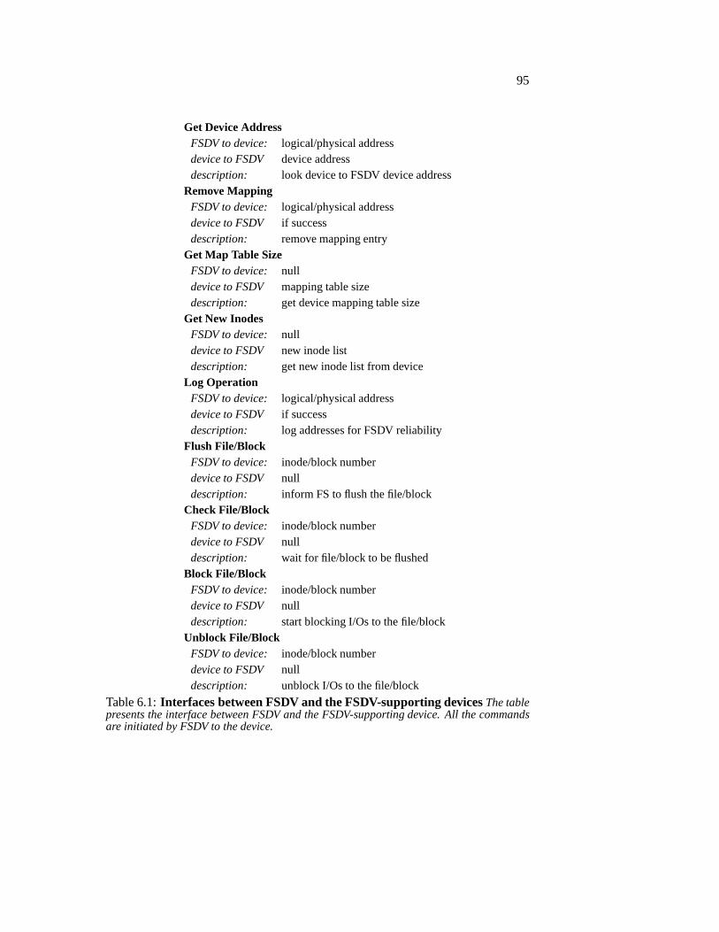
95
Get Device AddressFSDV to device: logical/physical addressdevice to FSDV device addressdescription: look device to FSDV device address
Remove MappingFSDV to device: logical/physical addressdevice to FSDV if successdescription: remove mapping entry
Get Map Table SizeFSDV to device: nulldevice to FSDV mapping table sizedescription: get device mapping table size
Get New InodesFSDV to device: nulldevice to FSDV new inode listdescription: get new inode list from device
Log OperationFSDV to device: logical/physical addressdevice to FSDV if successdescription: log addresses for FSDV reliability
Flush File/BlockFSDV to device: inode/block numberdevice to FSDV nulldescription: inform FS to flush the file/block
Check File/BlockFSDV to device: inode/block numberdevice to FSDV nulldescription: wait for file/block to be flushed
Block File/BlockFSDV to device: inode/block numberdevice to FSDV nulldescription: start blocking I/Os to the file/block
Unblock File/BlockFSDV to device: inode/block numberdevice to FSDV nulldescription: unblock I/Os to the file/block
Table 6.1:Interfaces between FSDV and the FSDV-supporting devicesThe tablepresents the interface between FSDV and the FSDV-supporting device. All the commandsare initiated by FSDV to the device.

96
Writedown: data, length, inode numberup: status, datadescription: write with associated inode number
Trim Blockdown: block numberup: nulldescription: invalidate a block
Add New Inodesdown: new inode listup: nulldescription: add new inodes to device
Flush File/Blockdown: nullup: inode/block numberdescription: inform FS to flush the file/block
Done Flush File/Blockdown: inode/block numberup: nulldescription: inform the device that file/block is flushed
Table 6.2:Interface between the File System and the FSDV-supporting DeviceThe table presents the interface between the file system thatis ported to FSDV and theFSDV-supporting device. The last three commands are for theonline FSDV only. The”Add New Inodes” command is for FSDV performance optimization.
We make a few changes of ext3 to support FSDV. First, to distinguish logicaladdresses from physical ones, we add to each physical address the value of thetotal device size; thus, the logical and the physical address spaces never overlap.We also change the device size boundary check to accommodatephysical addresses(the total size is doubled since we have two non-overlappingaddress spaces).
Second, we change the way the file system tracks address spaces and performsde-allocation to support FSDV. The file system uses the logical address bitmapsto track allocated logical addresses and uses a free space counter to track the totalamount of actual allocated (device) addresses. When a blockis devirtualized fromits logical address, its corresponding bit in the file systembitmap is unset. Doing sowill create more free logical addresses than the actual freespace in the device. Thefile system uses the free block counter to keep track of the amount of free spaceand does not change it during FSDV operations. During allocation, the file systemchecks this counter to determine the actual free space left on the device. When the

97
file system deletes a block in the physical address space, thefile system updates thefree block counter but does not change any bitmaps. When the file system deletesa block in the logical address space, it updates both the bitmap and the free blockcounter. The file system also sends a trim command to the device to inform it aboutthe de-allocation.
Third, the file system tracks the inode that a block belongs to(when it is allo-cated) and sends the inode identity to the device during a write.
Finally, the file system works with the device to support online FSDV. Specifi-cally, when the device sends the request of flushing a file or a block, the file systemadds such information (inode identity or block number) to a work queue. A workqueue handler then processes these files or blocks. For a file,the file system flushesall the blocks belonging to this file from the page cache and also clears the inodecache. For a block, the file system simply flushes it from the page cache. Afterthe file system finishes the flushing process, it informs the device with the inodeidentity or the block numbers. Table 6.2 summarizes the interfaces between the filesystem and the device (those that are changed because of FSDV).
6.2.4 Reliability Issues
Finally, several reliability and consistency issues can happen during the de-virtualizationprocess of FSDV. For example, the FSDV tool can crash before it completes itsde-virtualization operations of a file, leaving the metadata of the file inconsistent.Another situation can happen with the online FSDV, where theFSDV tool dies andthe device continues blocking file system I/Os.
We solve the reliability-related problems using several techniques. First, wemake sure that the device never deletes the old metadata block until the new versionof it has been committed. When the new metadata block is written, its old version isinvalidated at the same time; this operation is an overwriteand most normal devicesalready invalidates old blocks atomically with overwrites. Second, FSDV logs allthe old addresses a metadata block points to before FSDV processes the metadatablock. Doing so makes sure that if FSDV crashes after writingthe new metadatabut before the device removes the old mappings of the pointers in this metadatablock, the device can remove these mappings on recovery. When FSDV finishesits processing, the log on the device is removed. If a crash happens before FSDVfinishes, the logs will be replayed during recovery. Finally, we set a timeout ofdevice blocking file system I/Os to prevent dead or unresponsive FSDV tool.

98
6.3 Evaluation
In this section, we present our experimental evaluation of FSDV. Specifically, weanswer the following questions.
1. What are the changes to the file systems, the OS, the device firmware, andthe device I/O interface? Are the changes small and can they be easily im-plemented with existing systems?
2. How much indirection mapping space can FSDV remove? Can itbe removedin a dynamic way?
3. How does the amount of inodes processed by FSDV affect the mapping tablespace reduction and performance of FSDV?
4. What is the difference between different FSDV modes? How does the offlinemode compare to the online mode of FSDV? How do the online per-file andper-block modes compare?
5. What is the performance overhead of FSDV? How much does FSDV affectnormal foreground I/Os?
6. How does the optimization techniques affect the performance and mappingtable results?
We implemented the FSDV prototype as a user-level FSDV tool,and changedour emulated SSD device (described in Chapter 3), the ext3 file system, and theOS to support FSDV. The FSDV tool is implemented using thefsckcode base. Wechange several aspects of our SSD emulator to support FSDV. We also make smallchanges to the ext3 file system and the OS (the block layer in particular) to supportFSDV.
The total lines of code in the file system and the OS is 201 and is423 in the de-vice. Most of these changes are for handling de-allocation and FSDV performanceoptimization.Experimental environment: All experiments were conducted on a 64-bit Linux2.6.33 server, which uses a 3.3 GHz Intel i5-2500K processorand 16 GB of RAM.The emulated SSD used in our experiments has 5 GB size, 10 parallel flash planes,4 KB flash pages, and 256 KB erase blocks. Flash page read and write operationstake 25 and 200 microseconds and erase operation takes 1.5 milliseconds.Workloads: We use a set of different types of workloads for our evaluation.To mimic typical file system images, we use the Impressions tool [4]. For more

99
Workloads Total Size Files FileSizeF1 512 MB 1000 512 KBF2 1 GB 2000 512 KBF3 2 GB 2000 1 MBF4 4 GB 2000 2 MBF5 4 GB 4000 1 MBI1 3.6 GB 3000 1.2 MB
Table 6.3:Workloads Description This table describes the workloads property: thenumber of files and directories in the workloads and the average file size. Workloads F1to F5 represent different FileServer workloads from the FileBench suite [83] (with varyingnumber of files and directories). The workload I1 representsthe file system image generatedusing Impressions [4].
Map
ing
Tab
le S
ize
(MB
)
0
2
4
6
8
F1 F2 F3 F4 F5 I1
Remaining Space
InodeIndirectData
Figure 6.3:Mapping Table Space Reduction.We invoke the offline FSDV after run-ning different FileServer and Impressions workloads. The figure shows the mapping tablespace (in different types) reduction because of FSDV. The part below the horizontal linerepresents the remaining amount of the mapping table space that FSDV does not remove.
controlled workloads, we use the FileServer macro-benchmark in the FileBenchsuite [83] with different numbers of directories and different average file sizes.Table 6.3 summarizes the settings used with these workloads.
6.3.1 Mapping Table Reduction and FSDV Run Time
We first evaluate the mapping table space reduction of FSDV; the major goal ofFSDV is to reduce the mapping table space needed in a virtualized device. Fig-

100
Run
Tim
e (s
ec)
0
1
2
3
4
5
F1 F2 F3 F4 F5 I1
InodesIndirectBlocksDataUnmount+MountOther
Figure 6.4:FSDV Run Time. This figure plots the run time of the offline FSDV whende-virtualizing different FileServer and Impressions workloads. We break down the runtime into time spent on de-virtualizing inodes, indirect blocks, and data blocks, time tounmount and mount the file system, and the rest of the FSDV time.
ure 6.3 presents the amount of removed mapping tables with different FileServerworkloads and the Impressions file system image. Specifically, we show the amountof removed mapping entries for data blocks, indirect blocks, inode blocks, and theamount of remaining mappings.
We find that FSDV reduces device mapping table size by 75% to 96% (e.g.,from 8.4 MB to 0.3 MB for the F5 workload). Most of the mapping table reductionis with data blocks, which conforms with the fact that typical file system imagesconsist of data blocks [5]. We also find that larger files result in bigger data blockand indirect block mapping table reduction. Inode block mapping reduction in-creases with more files but is overall negligible for the FileServer workloads. TheImpressions workload has more inode block mapping reduction and less indirectblock reduction as compared to the FileServer workloads, indicating that it hassmaller file sizes. Finally, there is a small part of mappingsthat FSDV does notremove; most of these mappings are for global file system metadata such as blockgroup description blocks, data and inode bitmaps, and for directory blocks. Overall,we find that indirection mappings can be largely removed.
We also measure the run time of FSDV for these workloads; one of our goalsis to have short FSDV run time so that it has less impact on foreground I/Os (e.g.,FSDV can be scheduled during device idle time). Figure 6.4 shows the time takento run FSDV with the FileServer workloads and the Impressions file system image.Overall, we find that the run time of FSDV is small (from 2 to 5 seconds). We
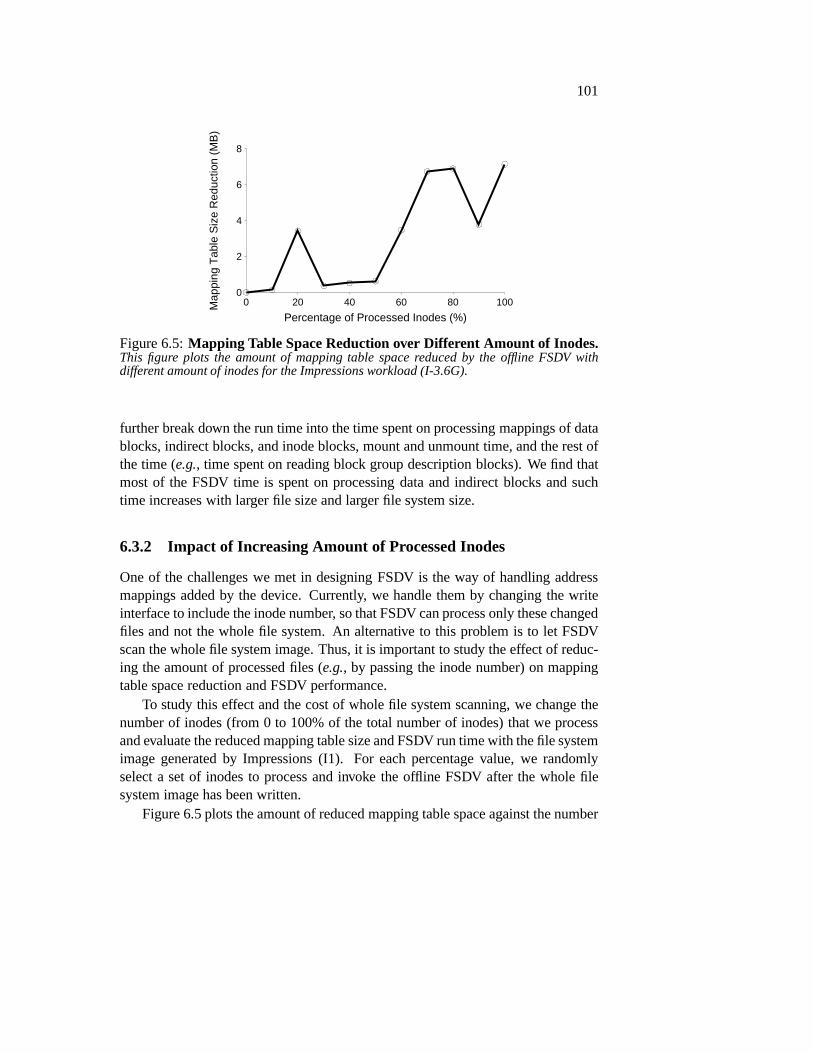
101
Percentage of Processed Inodes (%)0 20 40 60 80 100M
appi
ng T
able
Siz
e R
educ
tion
(MB
)
0
2
4
6
8
Figure 6.5:Mapping Table Space Reduction over Different Amount of Inodes.This figure plots the amount of mapping table space reduced bythe offline FSDV withdifferent amount of inodes for the Impressions workload (I-3.6G).
further break down the run time into the time spent on processing mappings of datablocks, indirect blocks, and inode blocks, mount and unmount time, and the rest ofthe time (e.g., time spent on reading block group description blocks). We find thatmost of the FSDV time is spent on processing data and indirectblocks and suchtime increases with larger file size and larger file system size.
6.3.2 Impact of Increasing Amount of Processed Inodes
One of the challenges we met in designing FSDV is the way of handling addressmappings added by the device. Currently, we handle them by changing the writeinterface to include the inode number, so that FSDV can process only these changedfiles and not the whole file system. An alternative to this problem is to let FSDVscan the whole file system image. Thus, it is important to study the effect of reduc-ing the amount of processed files (e.g., by passing the inode number) on mappingtable space reduction and FSDV performance.
To study this effect and the cost of whole file system scanning, we change thenumber of inodes (from 0 to 100% of the total number of inodes)that we processand evaluate the reduced mapping table size and FSDV run timewith the file systemimage generated by Impressions (I1). For each percentage value, we randomlyselect a set of inodes to process and invoke the offline FSDV after the whole filesystem image has been written.
Figure 6.5 plots the amount of reduced mapping table space against the number

102
Percentage of Processed Inodes (%)0 20 40 60 80 100
Run
Tim
e (s
ec)
0
1
2
3
4
5
Figure 6.6: Run Time over Different Amount of Inodes. This figure plots theoffline FSDV run time with different amount of inodes for the Impressions workload (I-3.6G).
of processed inodes. Overall, we find that for most of the times, with more inodesprocessed, more mappings are removed. However, such relationship is not linear.For example, there is a sudden increase from 40% to 60% of the inodes. Thereis also a sudden increase and drop in the amount of reduced mapping table spaceat 20% of the inodes. The file system generated by Impressionshas a certain filesize distribution (which mimics real file systems); certainfiles can be much biggerthan the rest of the files. Because of the randomness in the waywe select inodes toprocess, at 20% FSDV may happen to process one or more of the big files, resultingin a large reduction of mapping table space.
Figure 6.6 plots the time taken to run FSDV with different amount of processedinodes. As the number of inodes increase, the FSDV run time also increases. Dif-ferent from the mapping table size results, we find that the run time increase is moresteady.
Overall, we find that increasing the number of inodes to be processed by FSDVresults in more mapping table space reduction but higher FSDV run time. TheImpressions file system image that we use only has 3.6 GB data;for a large filesystem, the time to scan the whole file system can be much higher. Therefore,frequent whole file-system scans by FSDV are not a viable solution; one needs toeither reduce the number of inodes to process (our current solution) or increase thefrequency of FSDV (our future work).

103
Time (sec)0 60 120 180
Map
ping
Tab
le S
ize
(MB
)
0
4
8
12
NoFSDVOnlinePerBlockOnlinePerFileOffline
Figure 6.7:Mapping Table Space Over Time. This figure plots the mapping tablespace change over time running the FileServer F3 workloads with no FSDV, offline FSDV,and per-block and per-file online FSDV.
6.3.3 Comparison of Different Modes of FSDV
Offline and online are the two options of invoking FSDV. The online FSDV furtherhas two options, per-file and per-block processing. We now present our evaluationresults on the difference of these modes.
We first evaluate the mapping table space reduction of different modes of FSDV.In this set of experiments, we repeat the FileServer F3 workload (each running for60 seconds) and examine the mapping table space change. For the offline FSDVwe unmount the file system after each run, invoke FSDV, and then mount the filesystem. Figure 6.7 plots the mapping table space changes when there is no FSDVrunning (i.e., normal kernel), when running the offline FSDV, and when runningthe per-block and per-file online FSDV.
We first find that without FSDV, the mapping table size accumulates as theworkloads runs. The initial increase in the mapping table size (time 0 to 5 seconds)is due to the way FileBench runs; it pre-allocates directories and files before run-ning I/Os. With FSDV (both offline and online), the mapping table size decreasesand stays low, suggesting that FSDV can dynamically reduce indirection mappingcost.
Comparing the offline and the online modes, we find that the offline FSDVdecreases the mapping table size periodically (when it is invoked), while the onlineFSDV decreases the mapping table size when it first runs and the mapping table sizestays low. The online FSDV is triggered by the threshold of mapping table size;

104
when the mapping table size is above the threshold, the online FSDV is triggered.Therefore, the mapping table size always stays at or below the threshold. Betweenthe per-file and per-block online FSDV, we do not see a significant difference.
Run
Tim
e (s
ec)
0
0.4
0.8
1.2
1.6
2
F2 F3PerFile PerBlock Offline
Figure 6.8:Run Time of Different Modes of FSDV. This figure plots the run timeof the offline FSDV, per-file online FSDV, and per-block online FSDV with the F2 and F3workloads. Each run time value is an average of mutiple runs.
We then evaluate the run time of different modes of FSDV. Here, we use boththe FileServer F2 and F3 workloads; F2 has the same number of files as F3 butcontains smaller files. Figure 6.8 plots the average run timeof the offline, per-fileonline, and per-block online FSDV with these workloads. We first find that theper-block online FSDV takes longer time to run than the per-file online FSDV; theper-block FSDV exchange information with the device and thefile system for eachblock (e.g., syncing and blocking the block), creating higher overheadthan the per-file FSDV, which only does such operations once for each file. Comparing withthe offline FSDV, the online modes have longer run time with larger files and filesystems (F3), suggesting that the overhead of syncing and blocking data is higher.
For the online mode, one important overhead it causes is the blocking of fore-ground I/Os; we evaluate such blocked time for both the per-file and per-blockonline FSDV modes. Figure 6.9 plots the average time that I/Os to a block areblocked because of the per-file or the per-block FSDV. As expected, the per-fileFSDV blocks I/Os much longer than the per-block mode, since awhole file isblocked when per-file FSDV is processing a block in it, even though the rest of thefile is not being processed. We also find that when file size is larger, the blockedtime (with both per-file and per-block modes) is longer.
Overall, we find that the online FSDV allows more dynamism in the mapping

105
Avg
I/O
Blo
cked
Tim
e (m
sec)
.11
10
100
F2 F3PerFile PerBlock
Figure 6.9:I/O Blocked Time. This figure plots the average time a foreground I/O isblocked to a block (in log scale) because of the per-file and per-block FSDV when runningthe FileServer F2 and F3 workloads.
table space reduction than the offline mode. The online per-block mode takeslonger running time than the per-file mode but requires shorter foreground I/Oblocking time.
Thr
ough
put (
MB
/s)
0
200
400
600
800
1000
Baseline Offline OnlinePerFileOnlinePerBlock
Figure 6.10:Throughput of Foreground I/Os. This figure plots the throughput offoreground I/Os with no FSDV, with offline FSDV, and with per-block and per-file onlineFSDV when running the FileServer F3 workload.
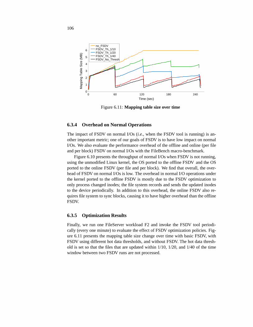
106
Time (sec)0 60 120 180 240
Map
ping
Tab
le S
ize
(MB
)
0
1
2
3
4
5
6
no_FSDVFSDV_Th_1/10FSDV_Th_1/20FSDV_Th_1/40FSDV_No_Thresh
Figure 6.11:Mapping table size over time
6.3.4 Overhead on Normal Operations
The impact of FSDV on normal I/Os (i.e., when the FSDV tool is running) is an-other important metric; one of our goals of FSDV is to have lowimpact on normalI/Os. We also evaluate the performance overhead of the offline and online (per fileand per block) FSDV on normal I/Os with the FileBench macro-benchmark.
Figure 6.10 presents the throughput of normal I/Os when FSDVis not running,using the unmodified Linux kernel, the OS ported to the offlineFSDV and the OSported to the online FSDV (per file and per block). We find that overall, the over-head of FSDV on normal I/Os is low. The overhead in normal I/O operations underthe kernel ported to the offline FSDV is mostly due to the FSDV optimization toonly process changed inodes; the file system records and sends the updated inodesto the device periodically. In addition to this overhead, the online FSDV also re-quires file system to sync blocks, causing it to have higher overhead than the offlineFSDV.
6.3.5 Optimization Results
Finally, we run one FileServer workload F2 and invoke the FSDV tool periodi-cally (every one minute) to evaluate the effect of FSDV optimization policies. Fig-ure 6.11 presents the mapping table size change over time with basic FSDV, withFSDV using different hot data thresholds, and without FSDV.The hot data thresh-old is set so that the files that are updated within 1/10, 1/20,and 1/40 of the timewindow between two FSDV runs are not processed.
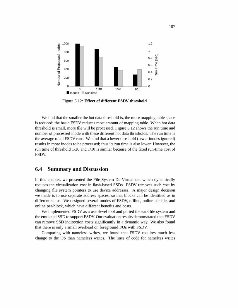
107
Num
ber
of P
roce
ssed
Inod
es
0
200
400
600
800
1000
0 1/40 1/20 1/10
Run
Tim
e (s
ec)
0
0.2
0.4
0.6
0.8
1
1.2
Inodes RunTime
Figure 6.12:Effect of different FSDV threshold
We find that the smaller the hot data threshold is, the more mapping table spaceis reduced; the basic FSDV reduces most amount of mapping table. When hot datathreshold is small, more file will be processed. Figure 6.12 shows the run time andnumber of processed inode with these different hot data thresholds. The run time isthe average of all FSDV runs. We find that a lower threshold (fewer inodes ignored)results in more inodes to be processed; thus its run time is also lower. However, therun time of threshold 1/20 and 1/10 is similar because of the fixed run-time cost ofFSDV.
6.4 Summary and Discussion
In this chapter, we presented the File System De-Virtualizer, which dynamicallyreduces the virtualization cost in flash-based SSDs. FSDV removes such cost bychanging file system pointers to use device addresses. A major design decisionwe made is to use separate address spaces, so that blocks can be identified as indifferent status. We designed several modes of FSDV, offline, online per-file, andonline per-block, which have different benefits and costs.
We implemented FSDV as a user-level tool and ported the ext3 file system andthe emulated SSD to support FSDV. Our evaluation results demonstrated that FSDVcan remove SSD indirection costs significantly in a dynamic way. We also foundthat there is only a small overhead on foreground I/Os with FSDV.
Comparing with nameless writes, we found that FSDV requiresmuch lesschange to the OS than nameless writes. The lines of code for nameless writes

108
in the OS is 4370 and is 201 for FSDV. The I/O interface change because of FSDVis also much smaller than nameless writes; only the write command needs to bechanged to include the inode number in the path from the OS to the device, whilenameless requires fundamental changes to the I/O interface. The change FSDVmakes to the write interface can easily be integrated into the ATA interface, sinceit only changes the forward path from the OS to the device. Finally, FSDV is moredynamic than nameless writes. FSDV can be invoked at any time(e.g., when thememory space pressure in the device is high or when the deviceis idle), thus caus-ing less overhead to foreground I/Os. Nameless writes are aninterface change toall the I/Os, and thus presents an overhead to all foregroundI/Os.

109
Chapter 7
Related Work
This chapter discusses various research efforts and real systems that are relatedto this dissertation. We first discuss literatures on flash memory and flash-basedstorage systems. We then discuss other systems that exhibitexcess indirection andprevious efforts to remove excess indirection. We close this chapter with with otherefforts in new storage system interfaces.
7.1 Flash-based Storage
In recent years, flash-based storage have become prevalent in both consumer andenterprise environment, and various new techniques and systems have been pro-posed for different problems related to flash-memory storage. In this section, wediscuss related works on various aspects of flash-based storage.
7.1.1 Flash Memory Management Software
Most flash-based SSDs use a flash translation layer (FTL) to virtualize their internalresources. To reduce the memory size required to store the mapping table for eachflash page (usually 2 KB to 8 KB page size), most modern SSD FTLsuse a hybridapproach to map most of the data at flash erase block granularity (usually 64 KBto 1 MB) and a small part of page-level mapping for on-going I/Os. A large bodyof work on flash-based SSD FTLs and file systems that manage them has beenproposed in recent years [24, 34, 48, 59, 60].
The poor random write performance of hybrid FTLs has drawn attention fromresearchers in recent years. The demand-based Flash Translation Layer (DFTL)was proposed to address this problem by maintaining a page-level mapping table

110
and writing data in a log-structured fashion [40]. DFTL stores its page-level map-ping table on the device and keeps a small portion of the mapping table in thedevice cache based on workload temporal locality. However,for workloads thathave a bigger working set than the device cache, swapping thecached mapping ta-ble with the on-device mapping table structure can be costly. There is also a spaceoverhead to store the entire page-level mapping table on device. The need for adevice-level mapping table is obviated with nameless writes and FSDV. Thus, wedo not pay the space cost of storing the large page-level mapping table in the deviceor the performance overhead of swapping mapping table entries.
A different approach to reduce the cost of indirection mapping in SSDs is tomove the SSD virtualization layer and the indirection mapping tables from SSDsto a software layer in the host. DFS is one such approach, where a software FTLin the host manages all the address allocations and mappingson top of raw flashmemory [46]. With this approach, the cost of virtualizationwithin the device isremoved, but such cost (though reduced) still exists in the host. Instead of movingthe FTL indirection layer to the host, nameless writes and FSDV remove the excessdevice indirection and thus do not incur any additional mapping table space cost atthe host. Moreover, nameless writes and FSDV both work with flash-based SSDsinstead of raw flash memory.
File systems that are designed for flash memory have also beenproposed inrecent years [41, 92, 93]. Most of these file systems use log-structured allocationand manage garbage collection and flash wears. With such file systems directlymanaging flash memory, there is no excess indirection or the associated indirectionmapping table cost. However, these file systems can only workwith raw flashmemory. They require knowledge of the flash memory internalssuch as OOBarea size. Operating directly on flash hardware can also be dangerous as we haveshown in Chapter 5. Instead, nameless writes and FSDV removeexcess indirectionby making small changes to existing file systems and flash-based SSDs and thusprovide a more generalized solution.
7.1.2 Hardware Prototypes
Research platforms for characterizing flash performance and reliability have beendeveloped in the past [14, 17, 26, 57, 58]. In addition, therehave been effortson prototyping phase-change memory based prototypes [7, 21]. However, mostof these works have focused on understanding the architectural tradeoffs internalto flash SSDs and have used FPGA-based platforms and logic analyzers to mea-sure individual raw flash chip performance characteristics, efficacy of ECC codes,and reverse-engineer FTL implementations. In addition, most FPGA-based proto-

111
types built in the past have performed slower than commercial SSDs, and prohibitanalyzing the cost and benefits of new SSD designs. Our nameless writes proto-typing efforts use OpenSSD with commodity SSD parts and havean internal flashorganization and performance similar to commercial SSD. There are other projectscreating open-source firmware for OpenSSD for research [87,88] and educationalpurposes [25]. Furthermore, we investigated changes to theflash-device interface,while past work looks at internal FTL mechanisms.
7.2 Excess Indirection and De-indirection
Excess indirection exists in many systems that are widely used today, as well as inresearch prototypes. In this section, we first discuss a few other systems that exhibitexcess indirection besides flash-based SSDs, the focus of this dissertation. We thendiscuss previous efforts in removing excess indirection.
Excess indirection arises in memory management of operating systems run-ning atop hypervisors [16]. The OS manages virtual-to-physical mappings for eachprocess that is running; the hypervisor, in turn, manages physical-to-machine map-pings for each OS. In this manner, the hypervisor has full control over the memoryof the system, whereas the OS above remains unchanged, blissfully unaware that itis not managing a real physical memory. Excess indirection leads to both space andtime overheads in virtualized systems. The space overhead comes from maintain-ing OS physical addresses to machine addresses mapping for each page and frompossible additional space overhead [2]. Time overheads exist as well in cases likethe MIPS TLB-miss lookup in Disco [16].
Excess indirection can also exist in modern disks. For example, modern disksmaintain a small amount of extra indirection that maps bad sectors to nearby loca-tions, in order to improve reliability in the face of write failures. Other examplesinclude ideas for “smart” disks that remap writes in order toimprove performance(for example, by writing to the nearest free location), which have been exploredin previous research such as Loge [28] and “intelligent” disks [89]. These smartdisks require large indirection tables inside the drive to map the logical address ofthe write to its current physical location. This requirement introduces new relia-bility challenges, including how to keep the indirection table persistent. Finally,fragmentation of randomly-updated files is also an issue.
File systems running atop modern RAID storage arrays provide another excel-lent example of excess indirection. Modern RAIDs often require indirection tablesfor fully-flexible control over the on-disk locations of blocks. In AutoRAID, a levelof indirection allows the system to keep active blocks in mirrored storage for per-

112
formance reasons, and move inactive blocks to RAID to increase effective capac-ity [91] and overcome the RAID small-update problem [75]. When a file systemruns atop a RAID, excess indirection exists because the file system maps logicaloffsets to logical block addresses. The RAID, in turn, maps logical block addressesto physical (disk, offset) pairs. Such systems add memory space overhead to main-tain these tables and meet the challenges of persisting the tables across power loss.
Because of the costs of excess indirection, system designers have long soughtmethods and techniques to reduce the costs of excess indirection in various systems.
The Turtles project [12] is an example of de-indirection in virtualized environ-ment. In a recursively-virtualized environment (with hypervisors running on hyper-visors), the Turtles system installs what the authors referto asmulti-dimensionalpage tables. Their approach essentially collapses multiple page tables into a singleextra level of indirection, and thus reduces space and time overheads, making thecosts of recursive virtualization more palatable.
Finally, we want to point out another type of redundancy and the removal of it:the redundancy (duplication) in data and de-duplication [98, 68, 55]. Different fromde-indirection whose purpose is to reduce the space and memory cost of excessindirection, the main purpose of de-duplication is to remove redundant copies ofdata to save storage space. The basic technique of de-duplication is simple, onlyone copy of redundant data is stored and multiple pointers tothis copy represent the(redundant) copies of the data. Maintaining and accessing such structures can causeoverhead, even though the cost has been reduced largely overthe past years [98]. Incontrast, the technique of de-indirection removes the redundant indirection directlywithout adding additional metadata (e.g., pointers), and thus does not have the sameoverhead as de-duplication. The major cost of de-indirection, however, lies in theneed to change storage system and interface design.
7.3 New Storage Interface
In this section, we discuss several new types of storage interfaces that are related tothis dissertation.
Range writes [8] use an approach similar to nameless writes.Range writeswere proposed to improve hard disk performance by letting the file system spec-ify a range of addresses and letting the device pick the final physical address of awrite. Instead of a range of addresses, nameless writes are not specified with anyaddresses, thus obviating file system allocation and movingallocation responsibil-ity to the device. Problems such as updating metadata after writes in range writesalso arise in nameless writes. We propose a segmented address space to lessen
113
the overhead and the complexity of such an update process. Another difference isthat nameless writes target devices that need to maintain control of data placement,such as wear leveling in flash-based devices. Range writes target traditional harddisks that do not have such responsibilities. Data placement with flash-based de-vices is also less restricted than traditional hard disks, since flash-based memoryhas uniform access latency regardless of its location.
In addition to nameless writes, there have been research andcommercial effortson exposing new flash interfaces for file systems [45], caching [30, 43, 67, 78],key-value stores [32], and object stores [49, 50, 96]. However, there is little knownto the application developers about the customized communication channels usedby the SSD vendors to implement new application-optimized interface. We focuson these challenges in our hardware prototype and propose solutions to overcomethem.
While we re-use the existing SATA protocol to extend the SSD interface inour hardware prototype, another possibility is to bypass the storage stack and sendcommands directly to the device. For example, Fusion-io andthe recent NVM Ex-press specification [72] attach SSDs to the PCI express bus, which allows a driver toimplement the block interface directly if wanted. Similarly, the Marvell DragonFlycache [65] bypasses SATA by using an RPC-like interface directly from a devicedriver, which simplifies integration and reduces the latency of communication.

114

115
Chapter 8
Future Work and Conclusions
The advent of flash-memory technology presents both opportunity and challenges.A major issue of flash-based SSDs is the space and performancecost of its indirec-tion.
In this dissertation, we proposed the technique of de-indirection to remove theSSD-level indirection. We started with presenting our efforts in building an accu-rate SSD emulator in Chapter 3. The emulator was used in laterparts in this disser-tation and can be used by general SSD-related research. We then presented a newtype of interface, the nameless writes, to remove SSD-levelindirection in Chap-ter 4. Next, we discussed our experience with prototyping nameless writes withreal hardware in Chapter 5. Finally, in Chapter 6, we presented another methodto perform de-indirection, a file system de-virtualizer, which overcomes the draw-backs of nameless writes. We focus on flash-based SSDs as a major use case butthe technique of de-indirection is applicable to other types of virtualized storagedevices.
In this chapter, we first summarize our de-indirection techniques and emulationand hardware experience in Section 8.1. We then list a set of lessons we learned inSection 8.2. Finally, we outline future directions where our work can possibly beextended in Section 8.3.
8.1 Summary
In this section, we summarize the contributions of this dissertation. We first reviewthe experience of building SSD emulator and implementing new design on realhardware. We then discuss the two methods of performing de-indirection: namelesswrites and FSDV.

116
8.1.1 Emulation and Hardware Experience
We implemented an SSD emulator, which works as a Linux pseudoblock deviceand supports three types of FTLs, page-level, hybrid, and nameless-writing FTLs.To model common types of SSDs with parallel planes, we leverages several tech-niques to reduce the computational overhead of the emulator. For example, weseparate data storage and SSD modeling into different threads. Our evaluation re-sults show that the emulator can model writes accurately with common types ofSSDs.
Beyond our efforts in building an accurate SSD emulator, we also built the newdesign of nameless writes with real hardware. When buildingthe nameless writeshardware prototype, we met a set of new challenges that we didnot foresee withemulation. For example, two major challenges are to integrate data in the I/O returnpath and to add upcalls from the device to the host OS. We proposed a split-FTLapproach, which leaves low-level flash operations in the device and runs the bulkof the FTL in the host OS.
Implementing nameless writes in a hardware prototype was a substantial ef-fort, yet ultimately proved its value by providing a concrete demonstration of theperformance benefits of the nameless writes design.
Overall, we found that the effort required to implement nameless writes onhardware is comparable to the effort needed to implement an SSD emulator. Whilewe faced challenges integrating new commands into the operating system andfirmware, with the SSD emulator we have also struggled to accurately model real-istic hardware and to ensure that we appropriately handled concurrent operations.With real hardware, there is no need to validate the accuracyof models, and there-fore, OpenSSD is a better environment to evaluate new SSD designs.
8.1.2 De-indirection with Nameless Writes
Our first method to perform de-indirection is nameless writes, a new write interfacebuilt to reduce the inherent costs of indirection. With nameless writes, only dataand no name (logical address) is sent by the file system to the device. The deviceallocates a physical address and returns it to the file systemfor future reads andoverwrites.
We met several challenges in designing and implementing nameless writes.First, there is a high performance cost caused by recursive updates to de-virtualizea block. We solve this problem by introducing the separationof address space intological and physical ones. Another challenge we met is the need for flash-basedSSDs to migrate physical blocks requires the physical addresses to be changed in

117
the file system. We used a new interface to upcall from the device to the file systemto inform it about the physical address change.
We ported the Linux ext3 file system to nameless writes and built namelesswrites with both our SSD emulator and with real hardware. Ourevaluation resultswith both emulation and real hardware showed that nameless writes greatly reducedspace costs and improved random-write performance.
8.1.3 File System De-Virtualizer
Our second method to perform de-indirection is the File System De-Virtualizer,which does not require fundamental changes to the OS and I/O interface (a majordrawback of nameless writes). FSDV is a light-weight user-level tool which scansfile system pointers and change them to use device physical addresses. FSDV canbe invoked periodically, when device mapping table is abovea threshold, or whenthe device is idle. We implemented an offline version of FSDV,which requires thefile system to be unmounted and mounted before and after the FSDV run. We alsoimplemented an online version, which does not require such detachment of the filesystem.
To achieve the goal of dynamic de-virtualization, we proposed a new designto separate different address spaces and block status within a file system. A blockcan use a logical block address which the device maps to its device address, an oldphysical address which the device maps to its current deviceaddress, or a deviceaddress with which no mapping is needed. We change the file system to treatbitmap as a tracking of block status in the logical address space and to use a freeblock counter for allocation.
Our evaluation results of FSDV show that it can remove deviceindirection costin a dynamic way with little overhead to foreground I/Os. We also found that FSDVrequires much less change to the OS is more dynamic than nameless writes.
8.2 Lessons Learned
In this section, we present a list of general lessons we learned while working onthis dissertation.
Excess indirection can be removed
Excess indirection exists in flash-based SSDs. From our experience of name-less writes and FSDV, we find that such excess indirection canbe removed.Nameless writes remove the SSD indirection by changing the I/O interface.

118
FSDV removes the SSD indirection by dynamically reading andchangingfile system pointers. As a result, both the space and performance overhead ofindirection is largely reduced. We believe that such de-indirection techniquescan be generalized into other systems that exhibit excess indirection.
Accurate emulation of fast devices that have internal parallelism is difficult
From our SSD emulation experience, we find that implementingSSD models(i.e., different FTLs) is relatively straightforward, while making the emulatorwork accurately with real systems requires careful thinking and much moreefforts.
A major challenge we find in implementing the SSD emulator is to supportSSD internal parallelism. To emulate the parallel processing of multiple I/Orequests using a single thread is difficult. Currently, we use two threads toseparately perform data storage and SSD modeling. Our emulator is accurateenough for the purpose of this dissertation (we focus on writes). However,to emulate faster operations accurately with more parallelism (e.g., the fasterread operations with 20 parallel planes), our SSD emulator is not accurateenough; increasing the number of cores used by the emulator can be onesolution.
Hardware is different from simulation and emulation
From our hardware experience with building nameless writeson the OpenSSDboard, we learned a set of lessons and found that real systemswith real hard-ware is much different from simulation and emulation.
First, we found that the OS stack to a real device (SATA-connected) is morecomplex than to an emulator. One needs to be careful when integrating newcommands in this stack (and different schedulers in the stack).
A bigger problem we met when we implemented nameless writes on realhardware is the difficulty in sending data from the device to the OS both as areturn of a file system write and as a upcall initiated by the device.
These and other problems that we met when building the hardware namelesswrites prototype were not foreseen when we built nameless writes with theSSD emulator. The lesson we learned in this experience is that one shouldalways have existing real systems in mind when designing newsystems.
Interface change is hard
Our initial thought when designing de-indirection methodsfor flash-basedSSDs is that through a simple interface change like namelesswrites, de-

119
indirection can be removed easily. However, when we startedto build name-less writes with real systems and real hardware, we found that interfacechange is actually very difficult.
Two major difficulties we met with nameless writes are addingdata to thereturn path of normal writes and augmenting the control pathwith deviceupcalls. These operations require significant changes to the ATA protocoland many OS layers, and turned out to be extremely difficult toimplement.
Because of these difficulties, we started to think about new solutions forde-indirection and designed the file system de-virtualizer. As compared tonameless writes, FSDV requires only small changes to the OS stack and theI/O interface, all of which can be implemented with real hardware systems.Another advantage of FSDV is that it can dynamically remove the cost ofindirection. For example, it can be scheduled at device idletime. Namelesswrites, on the other hand, add an overhead to each write.
Our efforts to build new interface with existing systems demonstrated that theability to extend the interface to storage may ultimately belimited by howeasily changes can be made to the OS storage stack. Research that proposesradical new interfaces to storage should consider how such adevice wouldintegrate into the existing software ecosystem. Introducing new commandsis possible by tunneling them through native commands.
8.3 Future Work
De-indirection is a general technique to remove excess indirection; we believe itcan be used in systems other than flash-based SSDs as well. In this section, weoutline various types of future work of de-indirection.
8.3.1 De-indirection with Other File Systems
Porting other types of file systems to use nameless writes andFSDV would bean interesting future direction. Here, we give a brief discussion about these filesystems and the challenges we foresee in changing them to usenameless writesand FSDV.
Linux ext2: The Linux ext2 file system is similar to the ext3 file system exceptthat it has no journaling. While we rely on the ordered journal mode to providea natural ordering for the metadata update process of nameless writes in ext3, we

120
need to introduce an ordering on the ext2 file system. Portingext2 to FSDV on theother hand is straightforward, since FSDV does not require any ordering and doesnot change the journaling part of ext3.
Copy-On-Write File Systems and Snapshots: As an alternative to journaling,copy-on-write(COW) file systems always write out updates to new free space;when all of those updates have reached the disk, a root structure is updated topoint at the new structures, and thus include them in the state of the file system.COW file systems thus map naturally to nameless writes. All writes to free spaceare mapped into the physical segment and issued namelessly;the root structure ismapped into the virtual segment. The write ordering is not affected, as COW filesystems all must wait for the COW writes to complete before issuing a write to theroot structure anyway.
A major challenge to perform de-indirection with COW file systems or otherfile systems that support snapshots or versions is that multiple metadata structurescan point to the same data block. For both nameless writes andFSDV, multiplemetadata blocks need to be updated to de-virtualize a block.One possible way tocontrol the number of metadata updates is to add a small amount of indirection fordata blocks that are pointed to by many metadata structures.An additional problemfor nameless writes is the large amount of associated metadata because of multiplepointers. We can use file system intrinsic back references, such as those in btrfs, orstructures likeBacklog[63] to represent associated metadata.
Extent-Based File Systems: One final type of file systems worth considering areextent-basedfile systems, such as Linux btrfs and ext4, where contiguous regionsof a file are pointed to via (pointer, length) pairs instead ofa single pointer perfixed-sized block.
Modifying an extent-based file system to use nameless writeswould require abit of work; as nameless writes of data are issued, the file system would not (yet)know if the data blocks will form one extent or many. Thus, only when the writescomplete will the file system be able to determine the outcome. Later writes wouldnot likely be located nearby, and thus to minimize the numberof extents, updatesshould be issued at a single time.
For FSDV, instead of the file tree that uses indirect blocks, the extent treeneeds to be processed to use physical addresses, which may break the continu-ity of the original logical addresses. Therefore, another mechanism is needed thatde-virtualizes extent trees.
Extents also hint at the possibility of a new interface for de-indirection. Specifi-
121
cally, it might be useful to provide an interface toreservea larger contiguous regionon the device; doing so would enable the file system to ensure that a large file isplaced contiguously in physical space, and thus affords a highly compact extent-based representation.
8.3.2 De-indirection of Redundant Arrays
As flash-based storage is gaining popularity in enterprise settings, a major prob-lem to be solve is the reliability of such storage. Redundancy solutions such asRAID [75] can be used to to provide reliability. One way to build reliable andhigh-performance storage layer is to use arrays of flash-based SSDs [64, 94].
The major problem with de-virtualizing redundant arrays ofSSDs is how un-derlying physical addresses of the devices and their migration (due to garbage col-lection and wear-leveling) can be associated with file system structure and RAIDconstruction.
Another important issue of de-virtualizing RAID is to maintain the array for-mation, such as mirroring and striping. Since we do not maintain address mappingafter de-indirection, it is difficult to maintain such arrayformation. For example,a nameless write can be allocated to two different physical addresses on a mir-rored pair. Since the file system stores only one physical address of the data, wecannot locate the data on the other mirrored pair. Even if we allocate the samephysical address on both pair, one of them can be migrated to adifferent physicaladdress because of garbage collection or wear-leveling. Similar problems happenwith striping and parity, too.
8.3.3 De-indirection in Virtualized Environment
Another interesting environment which can use de-indirection of storage devicesis the virtualized environment (e.g., when a guest OS uses a flash-based SSD asits storage device). The virtualized environment providesboth opportunities andchallenges to perform de-indirection.
With the virtualized environment, the hypervisor has better control and morefreedom in its access to various guest states. For example, currently FSDV requiresthe file system to send the inode number with each block write,while the hypervisorcan acquire such information (the inode number) by peaking into the guest memory.With this and other similar techniques performed by the hypervisor, we believe thatthe guest file system and its device interface will require noor only small changes.
Another situation in the virtualized environment is the useof device indirectionlayer in software [46]. The major challenge and difference in this situation is to

122
provide dynamic de-indirection; the indirection table space for a guest can be dy-namically allocated and changed over time. The hypervisor thus can dynamicallyremove a certain amount of indirection from one guest. FSDV is an initial effortto provide such dynamism; we believe that better solutions exist to make use ofhypervisor and the virtualized environment.
8.4 Closing Words
As software and hardware are getting more complex and are likely to remain so inthe future, redundant levels of indirection can exist in a single system for differentreasons. Such excess indirection results in both memory space and performanceoverhead.
We believe that after carefully examining the cause of excess indirection, wecan remove the redundant indirection without changing the basic layered structureof an existing system. We hope that this dissertation can help researchers and sys-tem builders by demonstrating how redundant indirection can be removed. We alsohope that this dissertation serves as a hint for future system designer to be cautiousabout adding another level of indirection.

Bibliography
[1] A. Modelli and A. Visconti and R. Bez. Advanced flash memory reliability. In Proceedingsof the IEEE International Conference on Integrated CircuitDesign and Technology (ICICDT’04), Austin, Texas, May 2004.
[2] K. Adams and O. Agesen. A Comparison of Software and Hardware Techniques for x86 Vir-tualization. InProceedings of the 13th International Conference on Architectural Support forProgramming Languages and Operating Systems (ASPLOS XIII), Seattle, Washington, March2008.
[3] N. Agarwal, V. Prabhakaran, T. Wobber, J. D. Davis, M. Manasse, and R. Panigrahy. DesignTradeoffs for SSD Performance. InProceedings of the USENIX Annual Technical Conference(USENIX ’08), Boston, Massachusetts, June 2008.
[4] N. Agrawal, A. C. Arpaci-Dusseau, and R. H. Arpaci-Dusseau. Generating Realistic Impres-sions for File-System Benchmarking. InProceedings of the 7th USENIX Symposium on Fileand Storage Technologies (FAST ’09), San Francisco, California, February 2009.
[5] N. Agrawal, W. J. Bolosky, J. R. Douceur, and J. R. Lorch. AFive-Year Study of File-SystemMetadata. InProceedings of the 5th USENIX Symposium on File and Storage Technologies(FAST ’07), San Jose, California, February 2007.
[6] N. Agrawal, V. Prabhakaran, T. Wobber, J. Davis, M. Manasse, and R. Panigrahy. Designtradeoffs for ssd performance. InUSENIX, 2008.
[7] A. Akel, A. M. Caulfield, T. I. Mollov, R. K. Gupta, and S. Swanson. Onyx: A protoypephase-change memory storage array. InHotStorage, 2011.
[8] A. Anand, S. Sen, A. Krioukov, F. Popovici, A. Akella, A. C. Arpaci-Dusseau, R. H. Arpaci-Dusseau, and S. Banerjee. Avoiding File System Micromanagement with Range Writes. InProceedings of the 8th Symposium on Operating Systems Design and Implementation (OSDI’08), San Diego, California, December 2008.
[9] A. C. Arpaci-Dusseau, R. H. Arpaci-Dusseau, and V. Prabhakaran. Removing the costs ofindirection in flash-based ssds with nameless writes. InHotStorage, 2010.
[10] R. H. Arpaci-Dusseau and A. C. Arpaci-Dusseau.Operating Systems: Three Easy Pieces.Arpaci-Dusseau Books, 0.5 edition, 2012.
[11] B. Tauras, Y. Kim, and A. Gupta. PSU Objected-Oriented Flash based SSD simulator.http://csl.cse.psu.edu/?q=node/321.
[12] M. Ben-Yehuda, M. D. Day, Z. Dubitzky, M. Factor, N. HarEl, A. Gordon, A. Liguori,O. Wasserman, and B.-A. Yassour. The Turtles Project: Design and Implementation of Nested
123

124
Virtualization. InProceedings of the 9th Symposium on Operating Systems Design and Imple-mentation (OSDI ’10), Vancouver, Canada, December 2010.
[13] S. Boboila and P. Desnoyers. Write Endurance in Flash Drives: Measurements and Analysis.In Proceedings of the 8th USENIX Symposium on File and Storage Technologies (FAST ’10),San Jose, California, February 2010.
[14] S. Boboila and P. Desnoyers. Write endurance in flash drives: Measurements and analysis. InFAST, 2010.
[15] J. S. Bucy and G. R. Ganger. The DiskSim Simulation Environment Version 3.0 ReferenceManual. Technical Report CMU-CS-03-102, Carnegie Mellon University, January 2003.
[16] E. Bugnion, S. Devine, and M. Rosenblum. Disco: RunningCommodity Operating Systems onScalable Multiprocessors. InProceedings of the 16th ACM Symposium on Operating SystemsPrinciples (SOSP ’97), pages 143–156, Saint-Malo, France, October 1997.
[17] T. Bunker, M. Wei, and S. Swanson. Ming II: A flexible platform for nand flash-based research.In UCSD TR CS2012-0978, 2012.
[18] S. Byan, J. Lentini, A. Madan, L. Pabon, M. Condict, J. Kimmel, S. Kleiman, C. Small, andM. W. Storer. Mercury: Host-side Flash Caching for the Data Center. InProceedings of the2012 IEEE Symposium on Mass Storage Systems and Technologies (MSST 2012), April 2012.
[19] Cade Metz. Flash Drives Replace Disks at Amazon, Facebook, Dropbox.htpp://www.wired.com/wiredenterprise/2012/06/flash-data-centers/all/, 2012.
[20] P. Cappelletti, C. Golla, and E. Zanoni.Flash Memories. Kluwer, 1999.
[21] A. M. Caulfield, A. De, J. Coburn, T. I. Mollov, R. K. Gupta, and S. Swanson. Moneta: A high-performance storage array architecture for next-generation, non-volatile memories. InIEEEMicro, 2010.
[22] F. Chen, T. Luo, and X. Zhang. CAFTL: A content-aware flash translation layer enhancing thelifespan of flash memory based solid state drives. InFAST, 2011.
[23] V. Chidambaram, T. Sharma, A. C. Arpaci-Dusseau, and R.H. Arpaci-Dusseau. ConsistencyWithout Ordering. InProceedings of the 10th USENIX Symposium on File and StorageTech-nologies (FAST ’12), San Jose, California, February 2012.
[24] T.-S. Chung, D.-J. Park, S. Park, D.-H. Lee, S.-W. Lee, and H.-J. Song. System Software forFlash Memory: A Survey. InProceedings of thei 5th International Conference on Embeddedand Ubiquitous Computing (EUC ’06), pages 394–404, August 2006.
[25] Computer Systems Laboratory, SKKU. Embedded Systems Design Class.http://csl.skku.edu/ICE3028S12/Overview.
[26] J. D. Davis and L. Zhang. FRP: a nonvolatile memory research platform targeting nand flash.In Workshop on Integrating Solid-state Memory into the Storage Hierarchy, ASPLOS, 2009.
[27] D. R. Engler, M. F. Kaashoek, and J. W. O’Toole. Exokernel: An Operating System Architec-ture for Application-Level Resource Management. InProceedings of the 15th ACM Symposiumon Operating Systems Principles (SOSP ’95), pages 251–266, Copper Mountain Resort, Col-orado, December 1995.
[28] R. M. English and A. A. Stepanov. Loge: A Self-Organizing Disk Controller. InProceed-ings of the USENIX Winter Technical Conference (USENIX Winter ’92), pages 237–252, SanFrancisco, California, January 1992.

125
[29] Facebook. Facebook FlashCache. http://www.github.com/facebook/flashcache.
[30] Fusion-io Inc. directCache. http://www.fusionio.com/data-sheets/directcache.
[31] Fusion-io Inc. ioDrive2.http://www.fusionio.com/products/iodrive2.
[32] Fusion-io Inc. ioMemory Application SDK.http://www.fusionio.com/products/iomemorysdk.
[33] Fusion-io Inc. ioXtreme PCI-e SSD Datasheet.http://www.fusionio.com/ioxtreme/PDFs/ioXtremeDS_v.9.pdf.
[34] E. Gal and S. Toledo. Algorithms and Data Structures forFlash Memories.ACM ComputingSurveys, 37:138–163, June 2005.
[35] E. Gal and S. Toledo. Algorithms and data structures forflash memories. InACM ComputingSurveys, 2005.
[36] J. L. Griffin, J. Schindler, S. W. Schlosser, J. S. Bucy, and G. R. Ganger. Timing-accurate Stor-age Emulation. InProceedings of the 1st USENIX Symposium on File and Storage Technologies(FAST ’02), Monterey, California, January 2002.
[37] L. M. Grupp, A. M. Caulfield, J. Coburn, S. Swanson, E. Yaakobi, P. H. Siegel, and J. K. Wolf.Characterizing Flash Memory: Anomalies, Observations, and Applications. InProceedings ofMICRO-42, New York, New York, December 2009.
[38] L. M. Grupp, J. D. Davis, and S. Swanson. The Bleak Futureof NAND Flash Memory. InProceedings of the 10th USENIX Symposium on File and StorageTechnologies (FAST ’12), SanJose, California, February 2012.
[39] H. S. Gunawi, V. Prabhakaran, S. Krishnan, A. C. Arpaci-Dusseau, and R. H. Arpaci-Dusseau.Improving file system reliability with i/o shepherding. InSOSP, pages 293–306, October 2007.
[40] A. Gupta, Y. Kim, and B. Urgaonkar. DFTL: a Flash Translation Layer Employing Demand-Based Selective Caching of Page-Level Address Mappings. InProceedings of the 14th In-ternational Conference on Architectural Support for Programming Languages and OperatingSystems (ASPLOS XIV), pages 229–240, Washington, DC, March 2009.
[41] J.-Y. Hwang. F2FS: Flash-friendly file system, 2013. Presented at the Embedded Linux Con-ference.
[42] Intel Corp. Understanding the flash translation layer (ftl) specification, December 1998. Appli-cation Note AP-684.
[43] Intel Corp. Intel Smart Response Technology.http://download.intel.com/design/flash/nand/325554.pdf, 2011.
[44] Intel Corporation. Intel X25-M Mainstream SATA Solid-State Drives.ftp://download.intel.com/design/flash/NAND/mainstream/mainstream-sata-ssd-datasheet.pdf.
[45] W. K. Josephson, L. A. Bongo, D. Flynn, and K. Li. DFS: a file system for virtualized flashstorage. InFAST, 2010.
[46] W. K. Josephson, L. A. Bongo, K. Li, and D. Flynn. DFS: A File System for Virtualized FlashStorage. InProceedings of the 8th USENIX Symposium on File and Storage Technologies (FAST’10), San Jose, California, February 2010.
126
[47] D. Jung, Y.-H. Chae, H. Jo, J.-S. Kim, and J. Lee. A Group-based Wear-Leveling Algorithm forLarge-Capacity Flash Memory Storage Systems. InProceedings of the 2007 international con-ference on Compilers, architecture, and synthesis for embedded systems (CASES ’07), October2007.
[48] J.-U. Kang, H. Jo, J.-S. Kim, and J. Lee. A Superblock-Based Flash Translation Layer forNAND Flash Memory. InProceedings of the 6th ACM & IEEE International conference onEmbedded software (EMSOFT ’08), Seoul, Korea, August 2006.
[49] Y. Kang, J. Yang, and E. L. Miller. Efficient storage management for object-based flash mem-ory. In Proceedings of the 18th Annual Meeting of the IEEE International Symposium onModeling, Analysis and Simulation of Computer and Telecommunication Systems (MASCOTS2010), August 2010.
[50] Y. Kang, J. Yang, and E. L. Miller. Object-based scm: An efficient interface for storage classmemories. InProceedings of the 27th IEEE Conference on Mass Storage Systems and Tech-nologies (MSST 2011), May 2011.
[51] A. Kawaguchi, S. Nishioka, and H. Motoda. A Flash-Memory Based File System. InPro-ceedings of the USENIX 1995 Winter Technical Conference, New Orleans, Louisiana, January1995.
[52] T. Kgil and T. N. Mudge. Flashcache: A nand flash memory file cache for low power webservers. InCASES, 2006.
[53] Y. Kim, B. Tauras, A. Gupta, D. M. Nistor, and B. Urgaonkar. FlashSim: A Simulator forNAND Flash-based Solid-State Drives. InProceedings of the 1st International Conference onAdvances in System Simulation (SIMUL ’09), Porto, Portugal, September 2009.
[54] S. Kleiman. Flash on compute servers, netapp inc. InHPTS, 2009.
[55] R. Koller and R. Rangaswami. I/O deduplication: Utilizing content similarity to improve I/Operformance. InFAST, 2010.
[56] J. Lee, E. Byun, H. Park, J. Choi, D. Lee, and S. H. Noh. CPS-SIM: Configurable and AccurateClock Precision Solid State Drive Simulator. InProceedings of the Annual ACM Symposiumon Applied Computing (SAC ’09), Honolulu, Hawaii, March 2009.
[57] S. Lee, K. Fleming, J. Park, K. Ha, A. M. Caulfield, S. Swanson, Arvind, , and J. Kim.BlueSSD: An open platform for cross-layer experiments for nand flash-based ssds. InWorkshopon Architectural Research Prototyping, 2010.
[58] S. Lee, K. Ha, K. Zhang, J. Kim, and J. Kim. FlexFS: a flexible flash file system for mlc nandflash memory. InUsenix ATC, 2009.
[59] S. Lee, D. Shin, Y.-J. Kim, and J. Kim. LAST: Locality-Aware Sector Translation for NANDFlash Memory-Based Storage Systems.In Proceedings of the International Workshop on Stor-age and I/O Virtualization, Performance, Energy, Evaluation and Dependability (SPEED2008),February 2008.
[60] S.-W. Lee, D.-J. Park, T.-S. Chung, D.-H. Lee, S. Park, and H.-J. Song. A Log Buffer-BasedFlash Translation Layer Using Fully-Associative Sector Translation. IEEE Transactions onEmbedded Computing Systems, 6, 2007.
[61] A. Leventhal. Flash Storage Today.ACM Queue, 6(4), July 2008.
[62] S.-P. Lim, S.-W. Lee, and B. Moon. FASTer FTL for Enterprise-Class Flash Memory SSDs.May 2010.

127
[63] P. Macko, M. Seltzer, and K. A. Smith. Tracking Back References in a Write-Anywhere FileSystem. InProceedings of the 8th USENIX Symposium on File and Storage Technologies (FAST’10), San Jose, California, February 2010.
[64] Mahesh Balakrishnan, Asim Kadav, Vijayan Prabhakaran, and Dahlia Malkhi. DifferentialRAID: Rethinking RAID for SSD Reliability. InProceedings of the EuroSys Conference (Eu-roSys ’10), Paris, France, April 2010.
[65] Marvell Corp. Dragonfly platform family. http://www.marvell.com/storage/dragonfly/, 2012.
[66] J. N. Matthews, D. Roselli, A. M. Costello, R. Y. Wang, and T. E. Anderson. Improving thePerformance of Log-Structured File Systems with Adaptive Methods. InProceedings of the16th ACM Symposium on Operating Systems Principles (SOSP ’97), pages 238–251, Saint-Malo, France, October 1997.
[67] M. Mesnier, J. B. Akers, F. Chen, and T. Luo. Differentiated storage services. InSOSP, 2011.
[68] D. T. Meyer and W. J. Bolosky. A Study of Practical Deduplication. InProceedings of the9th USENIX Symposium on File and Storage Technologies (FAST’11), San Jose, California,February 2011.
[69] MjM Data Recovery Ltd. Bad Sector Remapping.http://www.ukdatarecovery.com/articles/bad-sector-remapping.html.
[70] N. Mielke, T. Marquart, N. Wu, J. Kessenich, H. Belgal, E. Schares, and F. Trivedi. Bit errorrate in nand flash memories. InProceedings of the 46th IEEE International Reliability PhysicsSymposium (IRPS ’08), Phoenix, Arizona, April 2008.
[71] D. Narayanan, E. Thereska, A. Donnelly, S. Elnikety, and A. Rowstron. Migrating serverstorage to SSDs: analysis of tradeoffs. InProceedings of the EuroSys Conference (EuroSys’09), Nuremburg, Germany, April 2009.
[72] NVM Express. Nvm express revision 1.0b.http://www.nvmexpress.org/index.php/download_file/view/42/1/, July 2011.
[73] OCZ Technologies. Synapse Cache SSD.http://www.ocztechnology.com/ocz-synapse-cache-sata-iii-2-5-ssd.html.
[74] Y. Oh, J. Choi, D. Lee, and S. H. Noh. Caching less for better performance: Balancing cachesize and update cost of flash memory cache in hybrid storage systems. InFAST, 2012.
[75] D. Patterson, G. Gibson, and R. Katz. A Case for Redundant Arrays of Inexpensive Disks(RAID). In Proceedings of the 1988 ACM SIGMOD Conference on the Management of Data(SIGMOD ’88), pages 109–116, Chicago, Illinois, June 1988.
[76] V. Prabhakaran, L. N. Bairavasundaram, N. Agrawal, H. S. Gunawi, A. C. Arpaci-Dusseau, andR. H. Arpaci-Dusseau. IRON file systems. InSOSP, pages 206–220, 2005.
[77] M. Rosenblum and J. Ousterhout. The Design and Implementation of a Log-Structured FileSystem.ACM Transactions on Computer Systems, 10(1):26–52, February 1992.
[78] M. Saxena, M. M. Swift, and Y. Zhang. FlashTier: A lightweight, consistent and durablestorage cache. InEuroSys, 2012.
[79] M. Saxena, Y. Zhang, M. M. Swift, A. C. Arpaci-Dusseau, and R. H. Arpaci-Dusseau. GettingReal: Lessons in Transitioning Research Simulations into Hardware Systems. InProceedingsof the 11th USENIX Symposium on File and Storage Technologies (FAST ’13), San Jose, Cali-fornia, February 2013.

128
[80] M. She.Semiconductor Flash Memory Scaling. PhD thesis, University of California, Berkeley,2003.
[81] G. Soundararajan, V. Prabhakaran, M. Balakrishnan, and T. Wobber. Extending SSD Lifetimeswith Disk-Based Write Caches. InProceedings of the 8th USENIX Symposium on File andStorage Technologies (FAST ’10), San Jose, California, February 2010.
[82] D. Spinellis. Another Level of Indirection. In A. Oram and G. Wilson, editors,BeautifulCode: Leading Programmers Explain How They Think, chapter 17, pages 279–291. O’Reillyand Associates, 2007.
[83] Sun Microsystems. Solaris Internals: FileBench.http://www.solarisinternals.com/wiki/index.php/FileBench.
[84] Sun-Online. Sun Storage F5100 Flash Array.http://www.sun.com/F5100.
[85] S. S. Technology.Donovan Anderson. Mindshare Press, 2007.
[86] The OpenSSD Project. Indilinx Jasmine Platform.http://www.openssd-project.org/wiki/The_OpenSSD_Project.
[87] The OpenSSD Project. Participating Institutes.http://www.openssd-project.org/wiki/Jasmine_OpenSSD_Platform.
[88] VLDB Lab. SKKU University, Korea.http://ldb.skku.ac.kr.
[89] R. Wang, T. E. Anderson, and D. A. Patterson. Virtual Log-Based File Systems for a Pro-grammable Disk. InProceedings of the 3rd Symposium on Operating Systems Design andImplementation (OSDI ’99), New Orleans, Louisiana, February 1999.
[90] Western Digital. NAND Evolution and its Effects on Solid State Drive (SSD) Useable Life.http://www.wdc.com/WDProducts/SSD/whitepapers/ en/NAND Evolution 0812.pdf, 2009.
[91] J. Wilkes, R. Golding, C. Staelin, and T. Sullivan. The HP AutoRAID Hierarchical StorageSystem.ACM Transactions on Computer Systems, 14(1):108–136, February 1996.
[92] D. Woodhouse. JFFS2: The Journalling Flash File System, Version 2, 2003. http://sources.redhat.com/jffs2/jffs2.
[93] YAFFS. YAFFS: A flash file system for embedded use, 2006.http://www.yaffs.net/.
[94] Yiying Zhang and Andrea C. Arpaci-Dusseau and Remzi H. Arpaci-Dusseau. Warped mirrorsfor flash. InProceedings of the 29th IEEE Conference on Massive Data Storage (MSST ’13),Long Beach, California, May 2013.
[95] Yiying Zhang and Leo Prasath Arulraj and Andrea C. Arpaci-Dusseau and Remzi H. Arpaci-Dusseau. De-indirection for flash-based ssds with namelesswrites. In Proceedings of the10th USENIX Symposium on File and Storage Technologies (FAST ’12), San Jose, California,February 2012.
[96] Youyou Lu and Jiwu Shu and Weimin Zheng. Extending the lifetime of flash-based storagethrough reducing write amplification from file systems. InProceedings of the 10th USENIXSymposium on File and Storage Technologies (FAST ’12), San Jose, California, February 2013.
[97] Y. Zhang, L. P. Arulraj, A. C. Arpaci-Dusseau, and R. H. Arpaci-Dusseau. De-indirection forFlash-based SSDs with Nameless Writes. InProceedings of the 10th USENIX Symposium onFile and Storage Technologies (FAST ’12), San Jose, California, February 2012.
[98] B. Zhu, K. Li, and H. Patterson. Avoiding the Disk Bottleneck in the Data Domain Dedu-plication File System. InProceedings of the 6th USENIX Symposium on File and StorageTechnologies (FAST ’08), San Jose, California, February 2008.