DDR Technology of Model Based Processing and...
5
EAGE 69 th Conference & Exhibition — London, UK, 11 - 14 June 2007 P047 DDR Technology of Model Based Processing and Interpretation of VSP Data A.A. Tabakov* (Central Geophysical Expedition), A.V. Reshetnikov (Geovers Ltd), A.A. Mukhin (Geovers Ltd), V.L. Eliseev (Central Geophysical Expedition) & Y.A. Stepchenkov (Geovers Ltd) SUMMARY The ultimate goal of seismic data processing is a recovery of a model of an investigated medium. At the same time it is important to use some reference model of the media (particularly, velocity model) during processing and especially imaging procedures because only in this case one may expect to derive adequate results for further interpretation. At interpretation stage, during seismic image analysis it is possible to estimate the inconsistency of the model used and make appropriate corrections. These considerations lead to the concept of simultaneous iterative processing-interpretation of seismic data. DDR (Dynamic wave field Decomposition and velocity model Reconstruction) is the implementation of such concept for vertical seismic profiles data. DDR is an interactive tool of velocity model editing, ray tracing, wave field separation and joint imaging with the use of various wave types including multiples. The concept, general DDR processing workflow together with corresponding illustrations is presented in the paper.
Transcript of DDR Technology of Model Based Processing and...

EAGE 69th Conference & Exhibition — London, UK, 11 - 14 June 2007
P047DDR Technology of Model Based Processing andInterpretation of VSP DataA.A. Tabakov* (Central Geophysical Expedition), A.V. Reshetnikov(Geovers Ltd), A.A. Mukhin (Geovers Ltd), V.L. Eliseev (CentralGeophysical Expedition) & Y.A. Stepchenkov (Geovers Ltd)
SUMMARYThe ultimate goal of seismic data processing is a recovery of a model of an investigated medium. At thesame time it is important to use some reference model of the media (particularly, velocity model) duringprocessing and especially imaging procedures because only in this case one may expect to derive adequateresults for further interpretation. At interpretation stage, during seismic image analysis it is possible toestimate the inconsistency of the model used and make appropriate corrections. These considerations leadto the concept of simultaneous iterative processing-interpretation of seismic data. DDR (Dynamic wavefield Decomposition and velocity model Reconstruction) is the implementation of such concept for verticalseismic profiles data. DDR is an interactive tool of velocity model editing, ray tracing, wave fieldseparation and joint imaging with the use of various wave types including multiples. The concept, generalDDR processing workflow together with corresponding illustrations is presented in the paper.

EAGE 69th Conference & Exhibition — London, UK, 11 - 14 June 2007
Introduction As a rule, the processing and interpretation of seismic data are divided in time and often are carried out by the different software packages. Thus the information about model is used not in complete volume, and some simplified approaches have to be applied. Now most imaging procedures are based on ray-tracing and various migration transformations, but each of such methods separately has a number of serious disadvantages. Only parts of whole wave field, such as P or PS waves are used for imaging. Besides in many cases strongly simplified models of environment (such as flat boundaries, absence of gradients of velocities etc.) are used which results in large errors in interpretation. The first approach to the new technique of processing and interpretation of the VSP data in complex models consisting of adjacent system of arbitrary-non-uniform bodies with fragmentally regular borders is presented below. The regular waves of various types and orders have to be consistently located and subtracted from an initial field and projected on the image with use of basic model. For subtraction the time graph and amplitudes calculated on initial model of environment are used within the framework of a ray-tracing method. The obtained image can be used for correction of initial model, and this way is one of iterative steps to determine model which is adequate to interpreted wave field. Further we shall call this method as a method of Dynamic Decomposition and Reconstruction (DDR) (Tabakov et al., 2002). DDR technology The technology of VSP data processing by means of DDR technique consists of several procedures: 1. Construction of the first approximation to model as a result of kinematical inversion of
travel times and polarizations for visually correlated events in original data (Stepchenkov et al., 2005).
2. The synthetic wave parameters are calculated by ray-tracing method for strongest event. 3. The estimation of the form of a wave along calculated arrival times-graph with use of
designed distribution of amplitudes and polarization is carried out 4. The located wave is subtracted from an initial field and is projected to points of scattering
on the image with recalculation on factor of reflection of a P-wave on external perpendicular to border. The waves of various types from the same point of boundary are stacked with weights proportional to their original amplitude. The process is repeated for all types of waves and all boundaries until all regular events are subtracted and projected on section. Not only primary waves, but also multiples may used in the process.
After imaging the basic model can be corrected and the process may be repeated until the image will correspond to model with necessary accuracy (Reshetnikov et al., 2003). Fig. 1 shows the scheme of DDR technology.

EAGE 69th Conference & Exhibition — London, UK, 11 - 14 June 2007
Fig. 1. Scheme of DDR Technology
Joint imaging of the media using different types of waves Depending on boundaries configuration, different parts of interfaces can be exposed by one or more type of waves. Obviously, all types of waves contain information about properties of the media. It means that in process of imaging of the media all available information should be used. It is also necessary for the derived solution to particularly include “one-wave imaging” case. The way to calculate joint image is summing of the images from all types of waves. It is important to remember that all images dynamically correspond to different physical measures. Therefore images must be normalized before stacking. Resulting measure can be selected as value of P-waves reflection coefficient along normal to the boundary. Then normalization coefficient can be evaluated as where K – reflection coefficient, calculated using reference model;
0PK – normalized measure; N – number of summed images. Thus, for all boundaries of the model joint images can be calculated using all types of waves. These images can be composed into one seismic section. In this section amplitudes correspond to the reflection characteristic of the media (Reshetnikov et al., 2004). This method allows constructing of full seismic image which represents the media as values of true reflection coefficient along normal to the boundaries. Fig. 2 and 3 presents the images for different types of waves and joint image of the boundary.
KK
NP01
=γ

EAGE 69th Conference & Exhibition — London, UK, 11 - 14 June 2007
Fig. 2. Images for different types of waves
Fig. 3. Joint image of the boundary
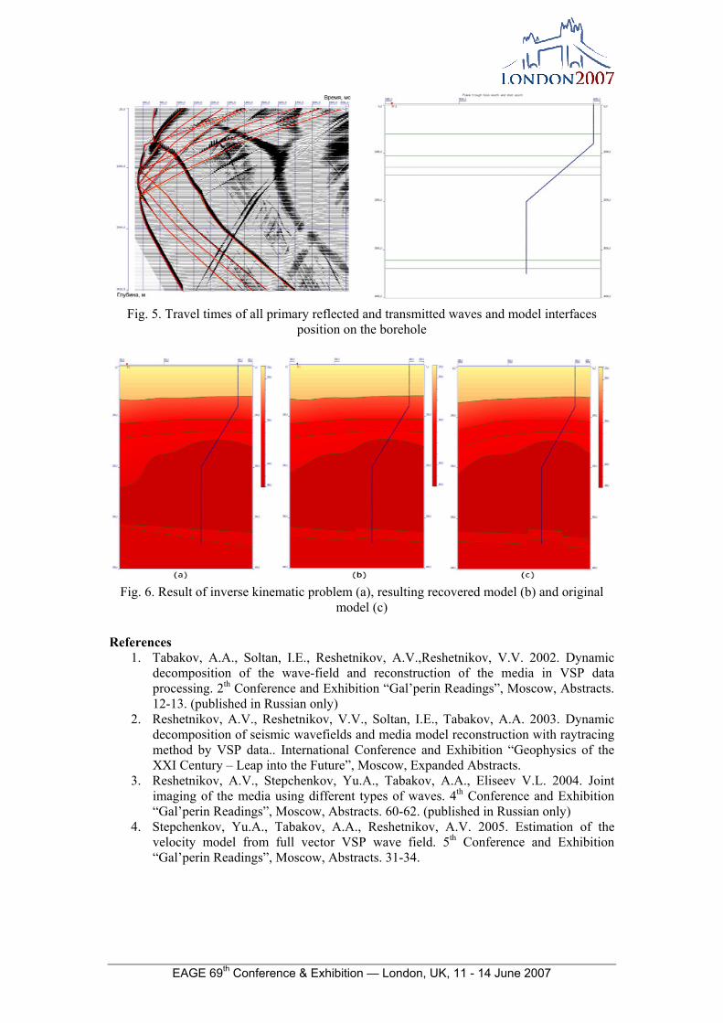
Results Numerical experiment was carried out to illustrate the proposed concept. Based on a given velocity model synthetic wave field was computed by finite-difference method (fig. 4). Then travel times of all primary reflected and transmitted waves were picked and depth marks of model interfaces were defined along the borehole (fig. 5). After that the procedure of kinematic inversion was implemented. The derived velocity model then was adjusted with the use of DDR techniques. Comparison of the resulting recovered model and original model is displayed in fig. 6.
Fig. 4. Given velocity model and synthetic wave field
EAGE 69th Conference & Exhibition — London, UK, 11 - 14 June 2007
Fig. 5. Travel times of all primary reflected and transmitted waves and model interfaces
position on the borehole
Fig. 6. Result of inverse kinematic problem (a), resulting recovered model (b) and original
model (c)
References 1. Tabakov, A.A., Soltan, I.E., Reshetnikov, A.V.,Reshetnikov, V.V. 2002. Dynamic
decomposition of the wave-field and reconstruction of the media in VSP data processing. 2th Conference and Exhibition “Gal’perin Readings”, Moscow, Abstracts. 12-13. (published in Russian only)
2. Reshetnikov, A.V., Reshetnikov, V.V., Soltan, I.E., Tabakov, A.A. 2003. Dynamic decomposition of seismic wavefields and media model reconstruction with raytracing method by VSP data.. International Conference and Exhibition “Geophysics of the XXI Century – Leap into the Future”, Moscow, Expanded Abstracts.
3. Reshetnikov, A.V., Stepchenkov, Yu.A., Tabakov, A.A., Eliseev V.L. 2004. Joint imaging of the media using different types of waves. 4th Conference and Exhibition “Gal’perin Readings”, Moscow, Abstracts. 60-62. (published in Russian only)
4. Stepchenkov, Yu.A., Tabakov, A.A., Reshetnikov, A.V. 2005. Estimation of the velocity model from full vector VSP wave field. 5th Conference and Exhibition “Gal’perin Readings”, Moscow, Abstracts. 31-34.