DDA 5005A/DDA 5005A XXL/ DDA 3000 DISK DRIVE...
8
DDA 5005A/DDA 5005A XXL/ DDA 3000 DISK DRIVE ANALYZERS
Transcript of DDA 5005A/DDA 5005A XXL/ DDA 3000 DISK DRIVE...
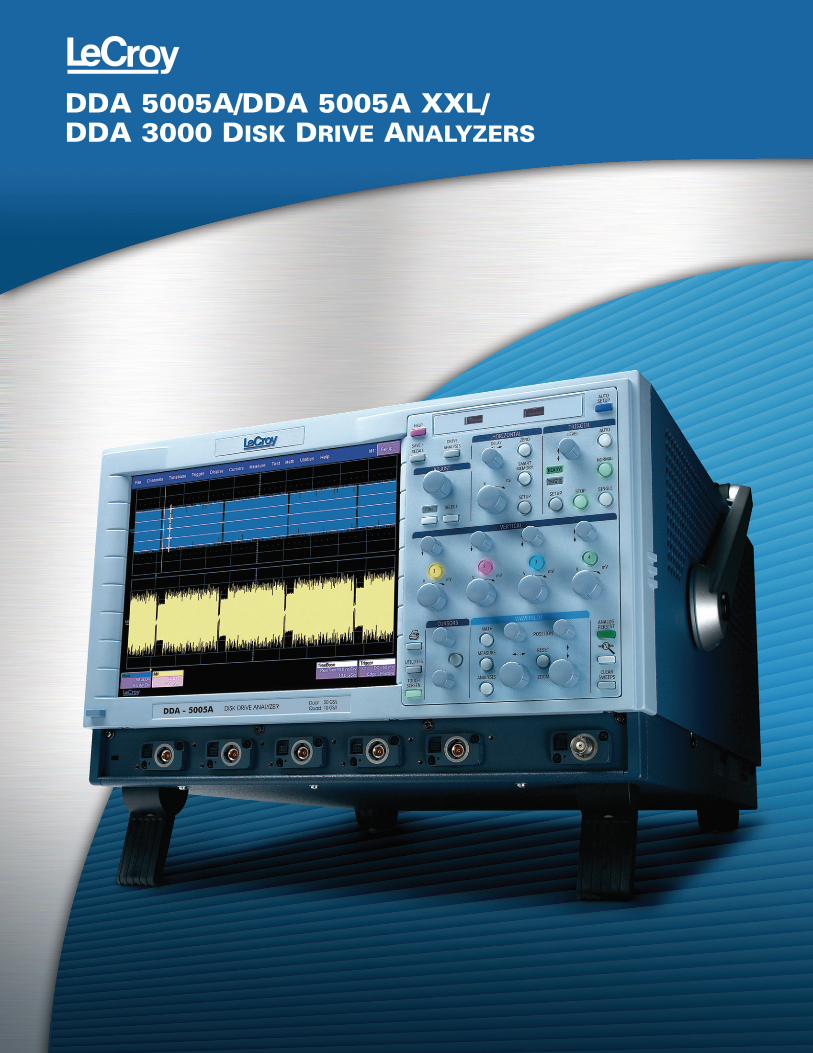
DDA 5005A/DDA 5005A XXL/DDA 3000 DISK DRIVE ANALYZERS
Maximum Performance
Since their inception, Disk DriveAnalysis (DDA) Series oscilloscopeshave helped data storage designengineers improve the time to marketof new products and acceleratedunderstanding and failure analysis onexisting drives. LeCroy continues that tradition with its powerful DiskDrive Analysis toolset, enabling you to capture, view, and analyze the wave shape of high-speed, complexdrive signals with speed and integrity.LeCroy’s X-Stream architectureintegrates SiGe “digitizer on a chip“technology and a specialized high-speedstreaming bus design to transfer data from the ADC to a proprietaryacquisition memory. The X-Streamarchitecture enables disk driveengineers to quickly, easily, andaccurately measure and analyze disk drive signals.
The DDA 5005A is designed for signalfidelity, whole track acqui sition andanalysis for read channel, media noiseanalysis, and head para metrics with thelongest acquisition memory standard.The DDA 3000 provides the samemeasurement capability at a lowerbandwidth. This unique product has the convenience of selectable 50 Ω or 1 MΩ inputs.
Excellence in Head, Disk, Track,
and Noise Analysis
The DDA Series analyzers incorporatethe tools to make you the mostefficient. The standard 100 Mpts ofcapture memory in the DDA 3000 (2 channel mode) and DDA 5005A XXL
provides 5 milliseconds of single-shot 20 GS/s capture on two channels,allowing multiple drive sectors to beacquired at once.
Long Memory and Flexibility
in Finding Problems
Acquire a head signal up to 5 GHz, andthen QuickZoom it from the front panel.The DDA copies and expands the drivesignal automatically. Simply scrollhorizontally and vertically to examineany sector. Multiple zooms let you viewup to eight separate areas of the head
2
Leading Features
• 3 or 5 GHz trigger bandwidth
• 10 GS/s sample rate/channel
• 20 GS/s dual-channel mode
• Up to 100 Mpts in
dual-channel mode
• Intuitive front panel and
touch screen interface
• Zoom and Multi-Zoom
on disk sectors
• One-button access to
Read Channel Emulation,
Servo Analysis, and
Disk Triggers
• Head Equalization,
Channel Emulation, and
SAM Histograms
• Segmented Memory
for sector-by-sector
parametric analysis
• Built-in PWxx, amplitude,
pulse shape, and ACSN
parametric measurements
• Customizable with MATLAB,
Mathcad, Visual Basic, or
Excel scripts
• Flexible connectivity to
networks, peripherals
with 100Base-T Ethernet,
and USB
DDA 5005A/DDA 5005A XXL/DDA 3000
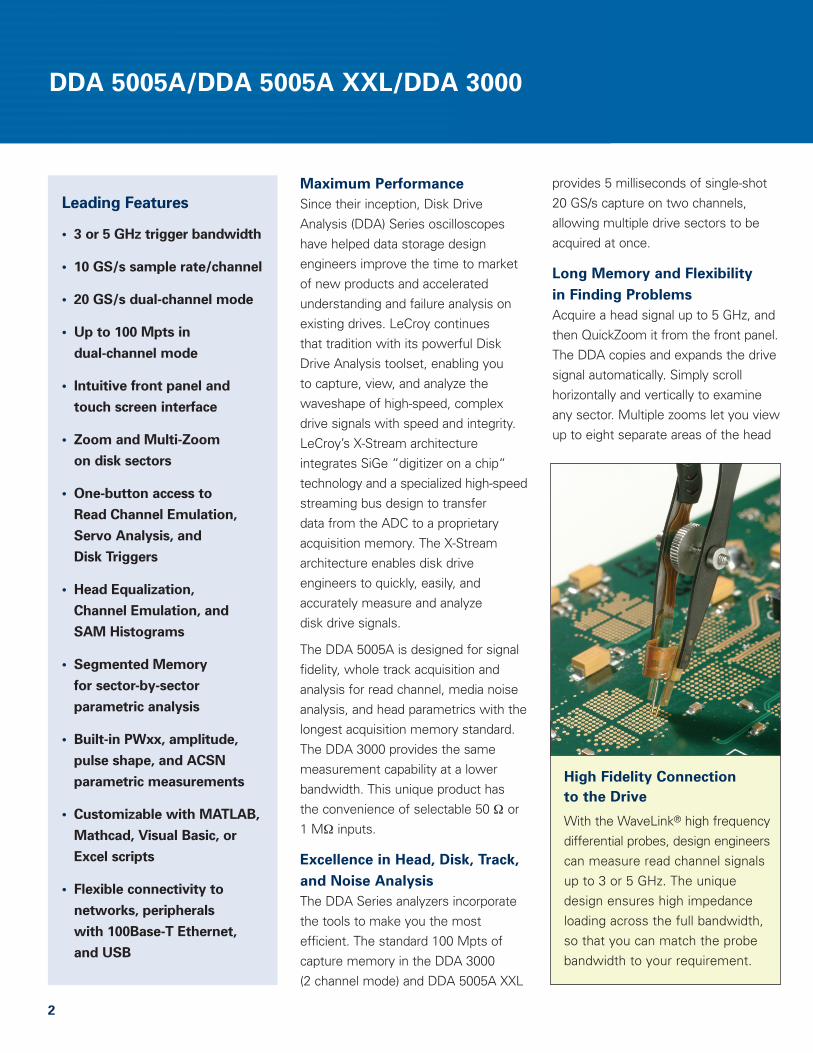
High Fidelity Connection
to the Drive
With the WaveLink® high fre quencydifferential probes, design engineerscan measure read channel signalsup to 3 or 5 GHz. The uniquedesign ensures high impedanceloading across the full bandwidth,so that you can match the probebandwidth to your requirement.
signal; each zoom comes in a distinctcolor. You can measure the timebetween two events accurately withhorizontal and vertical cursors. Diskdrive parameters let you characterize thepulse width variation or signal-to-noiseratio across a selectable region. FailureAnalysis engineers can store and recallgolden waveforms and panel setups tocompare problem drives with theknown good drives. Analog-to-digitalconverters running at speeds up to 20 GS/s ensure the right sensitivity to measure today’s high-speed readchannels. In every DDA, you can runyour customer-developed scripts toview the captured signal with the filtersmatched to your channel and media.Custom user scripts can be created inMATLAB, Mathcad, Visual Basic, oreven Excel.
Exceptional Trigger Performance
Disk Triggers allow you to set up aseries of events in the signal that thencause a trigger. For example, qualify the signal on the index signal and thencapture all the sectors of informationon the track. As memory is increased in the DDA, more sectors can becaptured, with up to 50 picosecond/sample time resolution. Up to 25,000sectors of data can be gathered withthe DDA 3000 or DDA 5005A XXL.
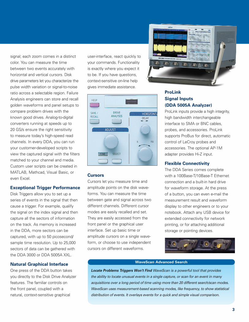
Natural Graphical Interface
One press of the DDA button takes you directly to the Disk Drive Analyzerfeatures. The familiar controls on the front panel, coupled with a natural, context-sensitive graphical
user-interface, react quickly toyour commands. Function ality is exactly where you expect it to be. If you have questions,context-sensitive on-line helpgives immediate assistance.
Cursors
Cursors let you measure time andamplitude points on the disk wave -forms. You can measure the timebetween gate and signal across twodifferent channels. Different cursormodes are easily recalled and set. They are easily accessed from the front panel or the graphical user interface. Set up basic time oramplitude cursors on a single wave -form, or choose to use independentcursors on different waveforms.
ProLink
Signal Inputs
(DDA 5005A Analyzer)
ProLink inputs provide a high integrity,high bandwidth interchangeable inter face to SMA or BNC cables,probes, and accessories. ProLinksupports ProBus for direct, automaticcontrol of LeCroy probes and acces sories. The optional AP-1Madapter provides Hi-Z input.
Flexible Connectivity
The DDA Series comes completewith a 100Base-T/10Base-T Ethernetconnection and a built-in hard drive for waveform storage. At the press of a button, you can even e-mail themeasurement result and waveformdisplay to other engineers or to yournotebook. Attach any USB device forextended connectivity for networkprinting, or for attaching additionalstorage or pointing devices.
3
WaveScan Advanced Search
Locate Problems Triggers Won’t Find WaveScan is a powerful tool that provides
the ability to locate unusual events in a single capture, or scan for an event in many
acquisitions over a long period of time using more than 20 different search/scan modes.
WaveScan uses measurement-based scanning modes, like frequency, to show statistical
distribution of events. It overlays events for a quick and simple visual comparison.
4
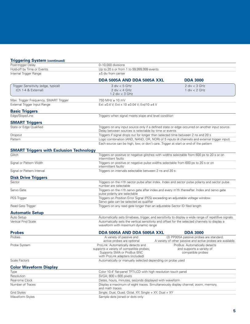
Specifications
Vertical System DDA 5005A AND DDA 5005A XXL DDA 3000Analog Bandwidth @ 50 Ω (-3 dB) 5 GHz 3 GHzInput Channels 4 4Bandwidth Limiter 20 MHz; 200 MHz; 1 GHz; 3 GHz; 4 GHz 25 MHz, 200 MHz, 1 GHzInput Impedance 50 Ω ±1.5% 50 Ω or 1 MΩ || 15 pF, 10 MΩ || 11 pF with PP005A probeInput Coupling DC, GND 1 MΩ: AC, DC, GND; 50 Ω: DCMaximum Input Voltage 2.5 Vrms; ±4 Vpeak 50 Ω: 5 Vrms, 1 MΩ: 100 V max. (peak AC: ≤ 5 KHz + DC)Vertical Resolution 8 bits; up to 11 bits with enhanced resolution (ERES)Sensitivity 2 mV–1 V/div fully variable 50 Ω: 2 mV–1 V/div fully variable;
1 MΩ: 2 mV–2 V/div fully variableOffset Range ±750 mV @ 2 mV–194 mV/div 50 Ω: ±700 mV @ 2 mV–4.95 mV/div.
±4 V @ 196 mV–1 V/div ±1.50 V @ 5 mV–100 mV/div.±10 V @ 102 mV–1 V/div.
1 MΩ: ±700 mV @ 2 mV–4.95 mV/div.±1.50 V @ 5 mV–100 mV/div.±20 V @ 102 mV–2 V/div.
DC Gain Accuracy ±1.5% of full scale; ±1% (typical)
Horizontal SystemTimebases Internal timebase common to 4 input channels; An external clock may be applied at the auxiliary inputClock Accuracy ≤ 1 ppm ≤ 5 ppmTime Interval Accuracy ≤ 0.06/SR + (1 ppm * Reading) ≤ 0.06/SR + (5 ppm * Reading)External Clock Frequency 30 MHz–2 GHz; 50 Ω impedance; 30 MHz–1 GHz; 50 Ω impedance;
applied at the auxiliary input applied at the auxiliary input Roll Mode – Operating Range N/A Up to 1000 s/div; lower limit determined by
memory length and sample rate
Acquisition SystemSingle-Shot Sample Rate/Ch 10 GS/s2 Channel Max. 20 GS/sMaximum Trigger Rate 150,000 waveforms/second (in Sequence Mode – up to 4 channels)
Acquisition Memory Max. Length (Mpts) Max. number of Segments;
(2 Ch/4 Ch) Sequence Mode
DDA 3000, DDA 5005A XXL 100M/48M 25,000DDA 5005A 48M/24M 20,000
Random Interleaved Sampling (RIS) 200 GS/s for repetitive signals, to 20 ps/div. Upper limit determined by sample rate and memory length settings.
Intersegment Time 6 µs
Acquisition ProcessingAveraging Summed or continuous averaging up to 1 million sweepsEnhanced Resolution (ERES) From 8.5 to 11 bits vertical resolutionEnvelope (Extrema) Envelope, linear, floor, or roof; for up to 1 million sweepsInterpolation Linear or Sin x/x
Triggering SystemModes Normal, Auto, Single, and StopSources Any input channel, External, Ext x 10, Ext/10, or line; slope and level unique to each source (except line trigger)Coupling DCPre-trigger Delay 0–100% of horizontal time scale
5
Triggering System (continued)
Post-trigger Delay 0–10,000 divisionsHold-off by Time or Events Up to 20 s or from 1 to 99,999,999 eventsInternal Trigger Range ±5 div from center
DDA 5005A AND DDA 5005A XXL DDA 3000
Trigger Sensitivity (edge, typical) 3 div < 5 GHz 2 div < 3 GHz(Ch 1-4 & External) 2 div < 4 GHz 1 div < 2 GHz
1.2 div < 3 GHz
Max. Trigger Frequency, SMART Trigger 750 MHz ≥ 10 mVExternal Trigger Input Range Ext ±0.4 V; Ext x 10 ±0.04 V; Ext/10 ±4 V
Basic TriggersEdge/Slope/Line Triggers when signal meets slope and level condition
SMART TriggersState or Edge Qualified Triggers on any input source only if a defined state or edge occurred on another input source.
Delay between sources is selectable by time or eventsDropout Triggers if signal drops out for longer than selected time between 2 ns and 20 sPattern Logic combination (AND, NAND, OR, NOR) of 5 inputs (4 channels and external trigger input)
Each source can be high, low, or don’t care. Trigger at start or end of the pattern
SMART Triggers with Exclusion TechnologyGlitch Triggers on positive or negative glitches with widths selectable from 600 ps to 20 s or on
intermittent faultsSignal or Pattern Width Triggers on positive or negative pulse widths selectable from 600 ps to 20 s or on
intermittent faultsSignal or Pattern Interval Triggers on intervals selectable between 2 ns and 20 s
Disk Drive TriggersSector Triggers on the n’th sector pulse after index. Index and sector pulse polarity and sector pulse
number are selectableServo Gate Triggers on the n’th servo gate after index and every m’th thereafter. Index and servo gate
pulse polarity are selectablePES Trigger Triggers on Position Error Signal (PES) exceeding an adjustable voltage window.
Servo gate can be selected as qualifierRead Gate Trigger Triggers on any read gate longer than an adjustable Sector ID filed length
Automatic SetupAuto Setup Automatically sets timebase, trigger, and sensitivity to display a wide range of repetitive signals Vertical Find Scale Automatically sets the vertical sensitivity and offset for the selected channels to display a
waveform with maximum dynamic range
Probes DDA 5005A AND DDA 5005A XXL DDA 3000Probes A variety of passive and (2) PP005A passive probes are standard.
active probes are optional A variety of other passive and active probes are available.Probe System ProLink: Automatically detects and ProBus: Automatically detects
supports a variety of compatible probes; and supports a variety of Supports SMA or ProBus BNC compatible probes
with ProLink adapters (included)Scale Factors Automatically or manually selected depending on probe used
Color Waveform DisplayType Color 10.4" flat-panel TFT-LCD with high resolution touch panelResolution SVGA; 800 x 600 pixelsReal-time Clock Dates, hours, minutes, seconds displayed with waveformNumber of Traces Display a maximum of eight traces. Simultaneously display channel, zoom, memory,
and math tracesGrid Styles Single, Dual, Quad, Octal, XY, Single + XY, Dual + XYWaveform Styles Sample dots joined or dots only
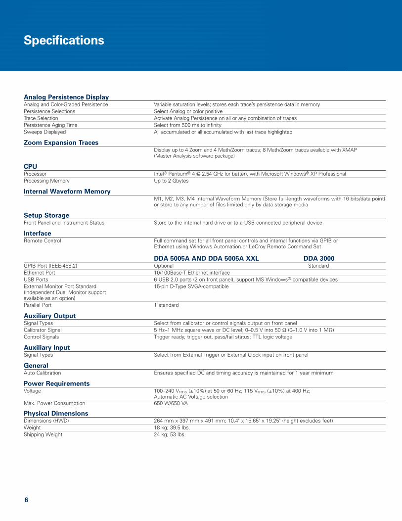
Analog Persistence DisplayAnalog and Color-Graded Persistence Variable saturation levels; stores each trace’s persistence data in memoryPersistence Selections Select Analog or color positiveTrace Selection Activate Analog Persistence on all or any combination of tracesPersistence Aging Time Select from 500 ms to infinitySweeps Displayed All accumulated or all accumulated with last trace highlighted
Zoom Expansion TracesDisplay up to 4 Zoom and 4 Math/Zoom traces; 8 Math/Zoom traces available with XMAP (Master Analysis software package)
CPUProcessor Intel® Pentium® 4 @ 2.54 GHz (or better), with Microsoft Windows® XP ProfessionalProcessing Memory Up to 2 Gbytes
Internal Waveform MemoryM1, M2, M3, M4 Internal Waveform Memory (Store full-length waveforms with 16 bits/data point)or store to any number of files limited only by data storage media
Setup StorageFront Panel and Instrument Status Store to the internal hard drive or to a USB connected peripheral device
InterfaceRemote Control Full command set for all front panel controls and internal functions via GPIB or
Ethernet using Windows Automation or LeCroy Remote Command Set
DDA 5005A AND DDA 5005A XXL DDA 3000GPIB Port (IEEE-488.2) Optional StandardEthernet Port 10/100Base-T Ethernet interfaceUSB Ports 6 USB 2.0 ports (2 on front panel), support MS Windows® compatible devicesExternal Monitor Port Standard 15-pin D-Type SVGA-compatible(independent Dual Monitor support available as an option) Parallel Port 1 standard
Auxiliary OutputSignal Types Select from calibrator or control signals output on front panelCalibrator Signal 5 Hz–1 MHz square wave or DC level; 0–0.5 V into 50 Ω (0–1.0 V into 1 MΩ)Control Signals Trigger ready, trigger out, pass/fail status; TTL logic voltage
Auxiliary InputSignal Types Select from External Trigger or External Clock input on front panel
General Auto Calibration Ensures specified DC and timing accuracy is maintained for 1 year minimum
Power RequirementsVoltage 100–240 Vrms (±10%) at 50 or 60 Hz; 115 Vrms (±10%) at 400 Hz;
Automatic AC Voltage selectionMax. Power Consumption 650 W/650 VA
Physical DimensionsDimensions (HWD) 264 mm x 397 mm x 491 mm; 10.4" x 15.65" x 19.25" (height excludes feet)Weight 18 kg; 39.5 lbs. Shipping Weight 24 kg; 53 lbs.
6
Specifications
7
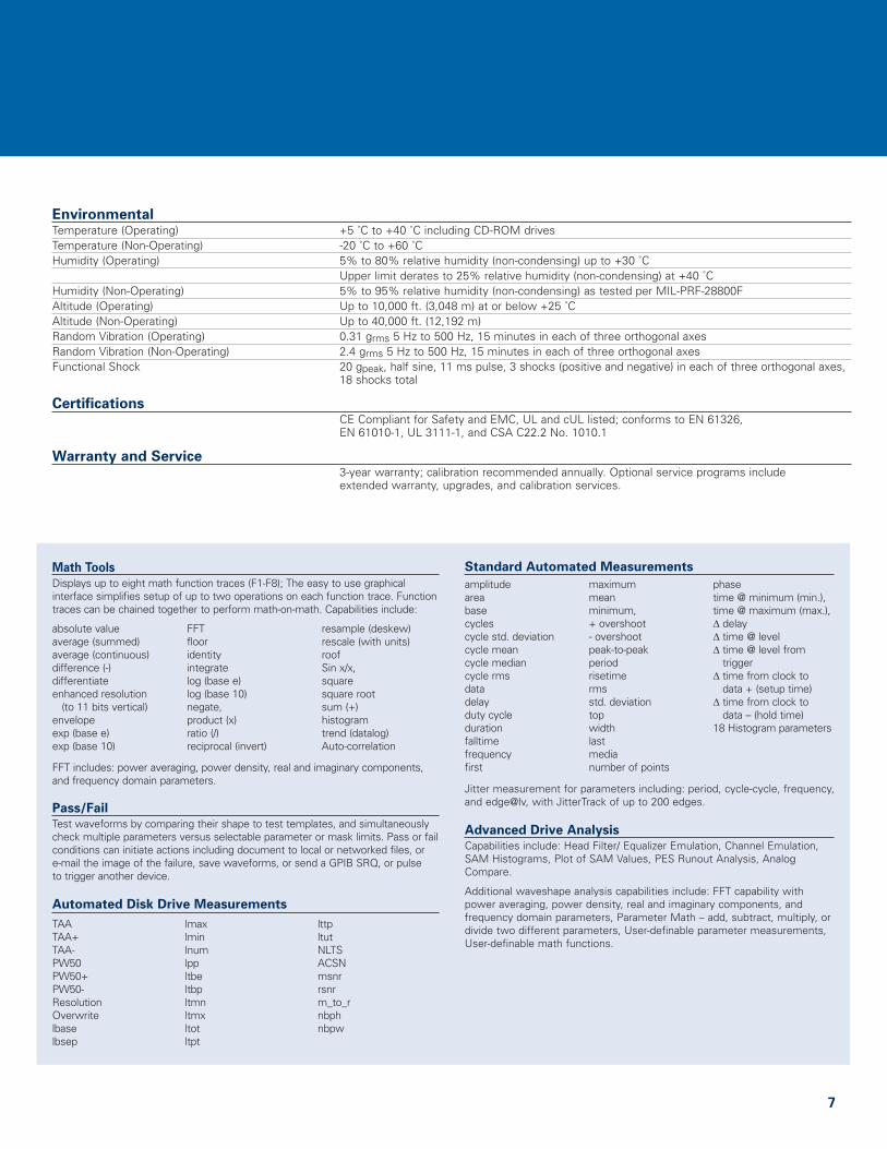
Math Tools
Displays up to eight math function traces (F1-F8); The easy to use graphicalinterface simplifies setup of up to two operations on each function trace. Functiontraces can be chained together to perform math-on-math. Capabilities include:
FFT includes: power averaging, power density, real and imaginary components,and frequency domain parameters.
Pass/Fail
Test waveforms by comparing their shape to test templates, and simultaneouslycheck multiple parameters versus selectable parameter or mask limits. Pass or failconditions can initiate actions including document to local or networked files, or e-mail the image of the failure, save waveforms, or send a GPIB SRQ, or pulse to trigger another device.
Automated Disk Drive Measurements
absolute valueaverage (summed) average (continuous) difference (-) differentiate enhanced resolution
(to 11 bits vertical)envelope exp (base e) exp (base 10)
FFT flooridentityintegratelog (base e) log (base 10)negate,product (x)ratio (/)reciprocal (invert)
resample (deskew)rescale (with units) roofSin x/x, squaresquare rootsum (+)histogramtrend (datalog)Auto-correlation
EnvironmentalTemperature (Operating) +5 ˚C to +40 ˚C including CD-ROM drivesTemperature (Non-Operating) -20 ˚C to +60 ˚CHumidity (Operating) 5% to 80% relative humidity (non-condensing) up to +30 ˚C
Upper limit derates to 25% relative humidity (non-condensing) at +40 ˚CHumidity (Non-Operating) 5% to 95% relative humidity (non-condensing) as tested per MIL-PRF-28800FAltitude (Operating) Up to 10,000 ft. (3,048 m) at or below +25 ˚CAltitude (Non-Operating) Up to 40,000 ft. (12,192 m)Random Vibration (Operating) 0.31 grms 5 Hz to 500 Hz, 15 minutes in each of three orthogonal axesRandom Vibration (Non-Operating) 2.4 grms 5 Hz to 500 Hz, 15 minutes in each of three orthogonal axesFunctional Shock 20 gpeak, half sine, 11 ms pulse, 3 shocks (positive and negative) in each of three orthogonal axes,
18 shocks total
CertificationsCE Compliant for Safety and EMC, UL and cUL listed; conforms to EN 61326, EN 61010-1, UL 3111-1, and CSA C22.2 No. 1010.1
Warranty and Service3-year warranty; calibration recommended annually. Optional service programs include extended warranty, upgrades, and calibration services.
TAATAA+TAA-PW50PW50+PW50-ResolutionOverwritelbaselbsep
lmaxlminlnumlppltbeltbpltmnltmxltotltpt
lttpltutNLTSACSNmsnrrsnrm_to_rnbphnbpw
Standard Automated Measurements
Jitter measurement for parameters including: period, cycle-cycle, frequency,and edge@lv, with JitterTrack of up to 200 edges.
Advanced Drive Analysis
Capabilities include: Head Filter/ Equalizer Emulation, Channel Emulation, SAM Histograms, Plot of SAM Values, PES Runout Analysis, AnalogCompare.
Additional waveshape analysis capabilities include: FFT capability withpower averaging, power density, real and imaginary components, andfrequency domain parameters, Parameter Math – add, subtract, multiply, ordivide two different parameters, User-definable parameter measurements,User-definable math functions.
amplitudeareabasecyclescycle std. deviationcycle meancycle mediancycle rmsdatadelayduty cycledurationfalltimefrequencyfirst
maximummeanminimum,+ overshoot- overshootpeak-to-peakperiodrisetimermsstd. deviationtopwidthlastmedianumber of points
phasetime @ minimum (min.),time @ maximum (max.),Δ delayΔ time @ levelΔ time @ level from
triggerΔ time from clock to
data + (setup time)Δ time from clock to
data – (hold time)18 Histogram parameters
Ordering Information
1-800-5-LeCroywww.lecroy.com
DDADSrevA_W1_05June07
Local sales offices are located throughout the world.
To find the most convenient one visit www.lecroy.com
© 2007 by LeCroy Corporation. All rights reserved. Specifications, prices, availability, and delivery subject to changewithout notice. Product or brand names are trademarks or requested trademarks of their respective holders.
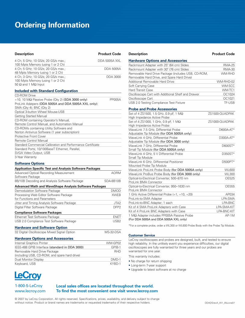
Description Product Code
4 Ch; 5 GHz; 10 GS/s; 20 GS/s max.; DDA 5005A XXL100 Mpts Memory (using 1 or 2 Ch)4 Ch; 5 GHz; 10 GS/s; 20 GS/s max.; DDA 5005A48 Mpts Memory (using 1 or 2 Ch)4 Ch; 3 GHz; 10 GS/s; 20 GS/s max.; DDA 3000100 Mpts Memory (using 1 or 2 Ch) 50 Ω and 1 MΩ Input
Included with Standard Configuration
CD-ROM Drive÷10, 10 MΩ Passive Probe (Qty 2) (SDA 3000 only) PP005AProLink Adatpers (DDA 5005A and DDA 5005A XXL only):SMA (Qty 4); BNC (Qty 2)Optical 3-button Wheel Mouse-USBGetting Started ManualCD-ROM containing Operator’s Manual, Remote Control Manual, and Automation ManualCD-ROMs containing Utility Software and Norton Antivirus Software (1 year subscription)Protective Front CoverRemote Control ManualStandard Commercial Calibration and Performance CertificateStandard Ports; 10/100BaseT Ethernet, Parallel, SVGA Video Output, USB3-Year Warranty
Software Options
Application Specific Test and Analysis Software Packages
Advanced Optical Recording Measurement AORMSoftware Package8B/10B Decoding and Analysis Software Package SDA-8B10B
Advanced Math and WaveShape Analysis Software Packages
Demodulation Software Package DMODProcessing Web Editor Software Package XWEBfor Functions and ParametersJitter and Timing Analysis Software Package JTA2Digital Filter Software Package DFP2
Compliance Software Packages
Ethernet Test Software Package ENETUSB 2.0 Compliance Test Software Package USB2
Hardware and Software Option
32 Digital Oscilloscope Mixed Signal Option MS-32-DSA
Hardware Options and Accessories
Internal Graphics Printer WM-GP02IEEE-488 GPIB Interface (standard in DDA 3000) GPIB-1Removable Hard Drive Package RHD(including USB, CD-ROM, and spare hard drive)Dual Monitor Display DMD-1Keyboard, USB KYBD-1
Description Product Code
Hardware Options and Accessories
Rackmount Adapter with 25" (64 cm) Slides RMA-25Rackmount Adapter with 30" (76 cm) Slides RMA-30Removable Hard Drive Package (includes USB, CD-ROM, WM-RHDRemovable Hard Drive, and Spare Hard Drive)Additional Removable Hard Drive WM-RHD-02Soft Carrying Case WM-SCCHard Transit Case WM-TC1Oscilloscope Cart with Additional Shelf and Drawer OC1024Oscilloscope Cart OC1021USB 2.0 Testing Compliance Test Fixture TF-USB
Probe and Probe Accessories
Set of 4 ZS1500, 1.5 GHz, 0.9 pF, 1 MΩ ZS1500-QUADPAKHigh Impedance Active ProbeSet of 4 ZS1000, 1 GHz, 0.9 pF, 1 MΩ ZS1000-QUADPAKHigh Impedance Active ProbeWaveLink 7.5 GHz, Differential Probe D600A-AT*Adjustable Tip Module (for DDA 5005A only)WaveLink 4 GHz, Differential Probe D300A-AT*Adjustable Tip Module (for DDA 3000 only)WaveLink 7 GHz, Differential Probe D600ST*Small Tip Module (for DDA 5005A only)WaveLink 4 GHz, 5 V Differential Probe D350ST*Small Tip ModuleWaveLink 6 GHz, Differential Positioner D500PT*Mounted Probe Tip ModuleWaveLink ProLink Probe Body (for DDA 5005A only) WL600WaveLink ProBus Probe Body (for DDA 3000 only) WL300Optical-to-Electrical Converter, 500–870 nm OE525ProLink BMA ConnectorOptical-to-Electrical Converter, 950–1630 nm OE555ProLink BMA Connector1 GHz Active Differential Probe (÷1, ÷10, ÷20) AP034ProLink-to-SMA Adapter LPA-SMAProLink-to-BNC Adapter; 1 each LPA-BNCKit of 4 SMA ProLink Adapters with Case LPA-SMA-KITKit of 4 ProLink BNC Adapters with Case LPA-BNC-KIT1 MΩ Adapter includes PP005A Passive Probe AP-1M(For DDA 5005A and DDA 5005A XXL only)
*For a complete probe, order a WL300 or WL600 Probe Body with the Probe Tip Module.
Customer Service
LeCroy oscilloscopes and probes are designed, built, and tested to ensurehigh reliability. In the unlikely event you experience difficulties, our digitaloscilloscopes are fully warranted for three years and our probes arewarranted for one year.
This warranty includes:• No charge for return shipping• Long-term 7-year support• Upgrade to latest software at no charge