
DDA-4300 & ZDA-4300RH User Manual (Revision 2)
23
4300-dda_ib_rev2.doc page 1 of 23 05/11/2009 IRT Eurocard Types DDA-4300 E3 / DS3 G.703 Data Distribution Amplifiers & ZDA-4300RH Handshake changeover assembly I R T Electronics Pty Ltd A.B.N. 35 000 832 575 26 Hotham Parade, ARTARMON N.S.W. 2064 AUSTRALIA National: Phone: (02) 9439 3744 Fax: (02) 9439 7439 International: +61 2 9439 3744 +61 2 9439 7439 Email: [email protected] Web: www.irtelectronics.com Designed and manufactured in Australia IRT can be found on the Internet at: http://www.irtelectronics.com IRT Communications www.irtcommunications.com
Transcript of DDA-4300 & ZDA-4300RH User Manual (Revision 2)
4300-dda_ib_rev2.doc page 1 of 23 05/11/2009
IRT Eurocard
Types DDA-4300 E3 / DS3 G.703 Data Distribution Amplifiers
& ZDA-4300RH
Handshake changeover assembly
I R T Electronics Pty Ltd A.B.N. 35 000 832 575 26 Hotham Parade, ARTARMON N.S.W. 2064 AUSTRALIA National: Phone: (02) 9439 3744 Fax: (02) 9439 7439 International: +61 2 9439 3744 +61 2 9439 7439 Email: [email protected] Web: www.irtelectronics.com
Designed and manufactured in Australia
IRT can be found on the Internet at: http://www.irtelectronics.com
IRT C
ommun
icatio
ns
www.irtco
mmunica
tions
.com
4300-dda_ib_rev2.doc page 2 of 23 05/11/2009
IRT Eurocard
Type DDA-4300 E3 / DS3 G.703 Data Distribution Amplifiers
& ZDA-4300RH
Handshake changeover assembly
Instruction Book
Table of Contents Section Page General Description 3
Functional Diagrams 5 DDA-4300 Technical Specifications 6 ZDA-4300RH Technical Specifications 7
Electrical characteristics of E3 & DS3 G.703 signals 8 Characteristics of Signal Types 9
Coding characteristics 9 G.703 data signal format 9
Technical Description 10 Handshake Operation 11
Pre-installation 14 Operational Safety 14
Configuration 15 Installation 16
Installation in frame 16 SMU-4000 Installation 17
Figure 1: SMU-4000 module 17 Front & rear panel diagrams 18
Operation 19 SNMP – What Is It? 20
DDA-4300 SNMP Functions 22 Maintenance & Storage 23 Warranty & Service 23
Equipment return 23
This instruction book applies to units fitted with firmware later than DDA4300i7A. IR
T Com
munica
tions
www.irtco
mmunica
tions
.com
4300-dda_ib_rev2.doc page 3 of 23 05/11/2009
IRT Eurocard Types DDA-4300
G.703 Data Distribution Amplifiers &
ZDA-4300RH Handshake changeover assembly
General Description The DDA-4300 is a data distribution amplifier that operates in accordance with the G.703 specification. Either E3 (34.368 Mb/s) or DS3 (44.736 Mb/s unframed or 44.210 Mb/s framed) data rates are possible by an on board switch selector.
The front panel of the DDA-4300 provides break access facility for the incoming signal in the form of a 1.6/5.6 connector link.
The DDA-4300 incorporates a protection facility for switching to signals from a standby module when a fault is detected.
Three outputs are provided at the rear of the module with an additional output for monitoring purposes on the front panel. The primary output is controlled by relays to provide a bypass signal from the input during a power failure.
On board switch setting allows an Alarm Indication Signal (AIS) detected in the data stream to generate a changeover request for a companion unit.
On loss of the input, the output can be set to give either no signal or an AIS signal output.
Indicators are provided on the front panel for: DC power Data loss AIS detect Module in service Module in standby
External alarm signals are also available on the rear of the module.
Changeover-inhibit and changeover-request switches are provided on the front panel for use where modules are linked in pairs for redundancy.
For this configuration, a special double width rear assembly (type ZDA-4300RH) is available to link the signal and logic sections of two modules.
Monitoring via a simple network management protocol (SNMP) is optionally possible when fitted with a plug-in SNMP board and run in an IRT 4000 series frame fitted with SNMP capability.
When used as a line equaliser or distribution amplifier the DDA-4300 may be housed in any of IRT’s standard Eurocard frames. When used in pairs for handshake operation only 3RU chassis types may be used so that the two modules are as close together as possible. The double width rear assemblies are designed specifically for this purpose and provide the best return loss characteristics. Cables should not be used to link the two modules. Details of frame types are available separately.
Standard features: • G.703 compliant. • For either E3 or DS3 G.703 data rates. • Adaptive cable input equalisation. • Data regeneration. • Monitor & break access facility. • Protection switching facility. • External alarms and bypass. • Redundant pair operation capability. • Optional SNMP capability.
IRT C
ommun
icatio
ns
www.irtco
mmunica
tions
.com
4300-dda_ib_rev2.doc page 4 of 23 05/11/2009
Equipment provided: Standard: ZDA-4300 Rear assembly for stand alone DDA-4300.
Accessories available:
ZDA-4300RH Double rear assembly for handshake: Connects two adjacent DDA-4300’s for automatic changeover of all three outputs in the event of a fault being detected.
IRT C
ommun
icatio
ns
www.irtco
mmunica
tions
.com
4300-dda_ib_rev2.doc page 5 of 23 05/11/2009
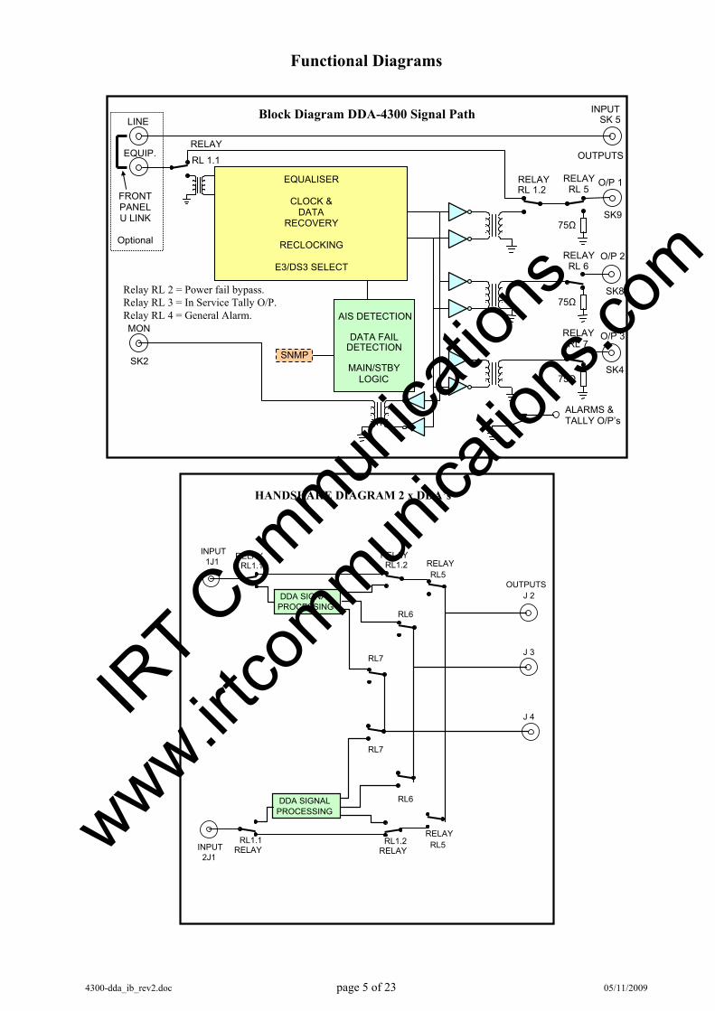
Functional Diagrams
INPUTSK 5
RELAY RL 1.1
RELAY RL 1.2
OUTPUTS
RELAYRL 6
ALARMS &TALLY O/P’s
AIS DETECTION
DATA FAILDETECTION
MAIN/STBYLOGIC
EQUALISER
CLOCK &DATA
RECOVERY
RECLOCKING
E3/DS3 SELECT
Relay RL 2 = Power fail bypass. Relay RL 3 = In Service Tally O/P. Relay RL 4 = General Alarm. MON
Block Diagram DDA-4300 Signal Path
RELAYRL 5 O/P 1
RELAYRL 7
SK9
O/P 2
SK8
O/P 3
SK4SK2
75Ω
75Ω
75Ω
EQUIP.
LINE
FRONT PANEL U LINK
Optional
SNMP
J 3
HANDSHAKE DIAGRAM 2 x DDA’s
J 2
J 4
INPUT 1J1
RELAY RL1.1
RELAYRL1.2
OUTPUTSDDA SIGNAL
PROCESSING
RELAYRL5
INPUT 2J1
RELAY RL1.1
RELAYRL1.2
DDA SIGNALPROCESSING
RELAYRL5
RL6
RL6
RL7
RL7
IRT C
ommun
icatio
ns
www.irtco
mmunica
tions
.com
4300-dda_ib_rev2.doc page 6 of 23 05/11/2009
DDA-4300 Technical Specifications Data: Generally in accord with CCITT G.703 specifications. Input: Type Transformer coupled. Impedance 75 Ω terminated. Equalisation Automatic for up to 250 m of Belden 8281 equivalent. Outputs: Type Transformer coupled. Number 3 switched, regenerated, reclocked outputs located on rear connection
assembly and one located on front panel. Impedance 75 Ω source terminated. Electrical characteristics: Data rate E3 (34.368 Mb/s) or DS3 (44.736 Mb/s unframed, 44.210 Mb/s framed) - Switch selectable. Other See G.703 specification for selected data rate. Controls & alarms: DC power. Data loss. “Blue Book” AIS detect. Module in service. Module in standby. Bypass. General alarm. Changeover request. Connectors: Data: BNC. Alarm: Krone LSA plus. Other: Power requirements 28 Vac CT (14-0-14) or ± 16 Vdc. Temperature range 0 - 50° C ambient. Mechanical Suitable for mounting in IRT 19" Eurocard rack chassis with input output
connections on the rear panel. Finish: Front panel Grey background, silk-screened black lettering & red IRT logo. Rear assembly Detachable silk-screened PCB with direct mount connectors to Eurocard
and external signals. Dimensions 31 mm x 3 U x 220 mm IRT Eurocard. Standard accessories DDA-4300 rear connector assembly. Optional accessories Instruction manual. ZDA-4300RH double rear assembly, for handshake connection of two
DDA-4300's.
Due to our policy of continuing development, these specifications are subject to change without notice.
IRT C
ommun
icatio
ns
www.irtco
mmunica
tions
.com
4300-dda_ib_rev2.doc page 7 of 23 05/11/2009
ZDA-4300RH Technical Specifications Controls & alarms:
Outputs: Bypass Contact closure to ground if power has failed. General Alarm Contact closure to ground if:- a. Data Loss is detected OR b. AIS is detected AND the AIS disable switch (SW3-4) is not set.
AIS detection is defined as at least 2048 consecutive data “1”s. Data Loss is defined as less than 120 data “1”s in 512 34 Mbit clock periods.
In Service (Main) Path Indication Transistor switch to ground if card is active (if DA version is equipped). Connectors: Data: BNC. Alarm: Krone LSA plus. In Service (Main) Path: Krone LSA plus. Changeover logic: A changeover to the companion module will occur under any of the following conditions:
Loss of input signal AIS detection alarm (provided AIS is not disabled by switch SW3-4) Loss of power
In all of the above cases switching will only occur if: companion module is able to provide an output free of the same defects and changeover inhibit switch is not activated on either module.
Priority logic: The priority switching in normal mode follows non reverting logic which dictates:
In the event of failure of main then standby DDA will assume control and become Main causing the failed path DDA to become Standby.
This implies that when the failed path is restored that it will remain as Standby and not become Main unless either a failure of Main occurs or a manual changeover is requested. Power on reset. When power is applied to the pair, the power on reset signal will set the module which was last enabled as Main as Main and the other module will be forced to act as Reserve. When power is applied to a pair for the first time it may be necessary to force the desired module to become Main by pressing the Change Request button on the front panel of the desired module. The Main module will be indicated by the In Service LED being lit on the front panel.
Due to our policy of continuing development, these specifications are subject to change without notice.
IRT C
ommun
icatio
ns
www.irtco
mmunica
tions
.com
4300-dda_ib_rev2.doc page 8 of 23 05/11/2009
Electrical characteristics of E3 & DS3 G.703 signals: Electrical characteristics ITU-T G.703 34.368 Mb/s (E3): Cable Type Coaxial Impedance 75 Ω Signal level 1.0 V Nominal pulse width 14.55 ns Code conversion HDB3 Pulse shape Fig. 17 of ITU-T G.703 Specification (11/2001). Jitter at input port Section 7 of ITU-T G.823 Specification (03/2000). Jitter at output port Section 5 of ITU-T G.823 Specification (03/2000). Return loss at input ports:
860 KHz to 1720 KHz 12 dB 1720 KHz to 34368 KHz 18 dB 34368 KHz to 51550 KHz 14 dB
Electrical characteristics ITU-T G.703 Shaped 44.736 Mb/s (DS3): Cable Type Coaxial Impedance 75 Ω Signal level
Power at 22.368 MHz +1.8 dBm to +5.7 dBm. Power at 44.736 MHz >20 dBm below power at 22.368 MHz.
Code conversion B3ZS Pulse shape Fig. 14 of ITU-T G.703 Specification (11/2001).
IRT C
ommun
icatio
ns
www.irtco
mmunica
tions
.com
4300-dda_ib_rev2.doc page 9 of 23 05/11/2009
Characteristics of Signal Types Coding characteristics - G.703: The HDB3 (High Density Bi-polar of order 3) code as defined in G.703 for 34,368 Kb/s is as follows:
Binary 1 bits are represented by alternate positive and negative pulses and binary 0 bits by spaces. Exceptions are made when strings of successive 0 bits occur in the binary signal. Each block of 4 successive zeros is replaced by 000V or B00V where B is an inserted pulse of the correct polarity and V is an inserted pulse violating the polarity rule. The choice of 000V or B00V is made so that the number of B pulses between consecutive V pulses is odd so that successive V pulses are of alternate polarity and so no DC component is introduced.
The B3ZS (Bipolar with Three Zero Substitution) (Also designated HDB2 - High Density Bi-polar of order 2) code as defined in G.703 for 44,736 Kb/s is as follows:
Binary 1 bits are represented by alternate positive and negative pulses and binary 0 bits by spaces. Exceptions are made when strings of successive 0 bits occur in the binary signal. Each block of 3 successive zeros is replaced by 00V or B0V. The choice of 00V or B0V is made so that the number of B pulses between consecutive V pulses is odd, so that successive V pulses are of alternate polarity and so no DC component is introduced.
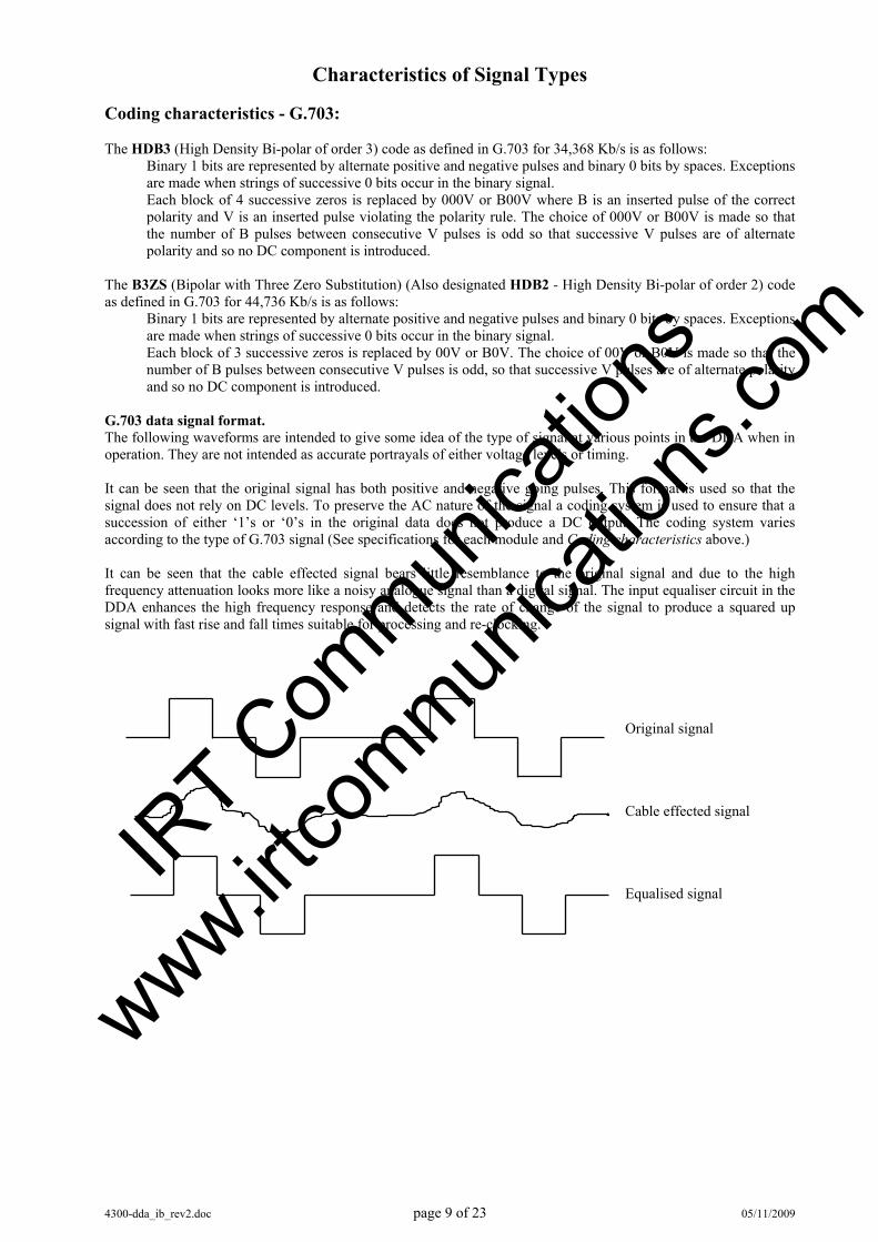
G.703 data signal format. The following waveforms are intended to give some idea of the type of signal at various points in the DDA when in operation. They are not intended as accurate portrayals of either voltage levels or timing. It can be seen that the original signal has both positive and negative going pulses. This format is used so that the signal does not rely on DC levels. To preserve the AC nature of the signal a coding system is used to ensure that a succession of either ‘1’s or ‘0’s in the original data does not produce a DC output. The coding system varies according to the type of G.703 signal (See specifications for each module and Coding characteristics above.) It can be seen that the cable effected signal bears little resemblance to the original signal and due to the high frequency attenuation looks more like a noisy analogue signal than a digital signal. The input equaliser circuit in the DDA enhances the high frequency response and detects the rate of change of the signal to produce a squared up signal with fast rise and fall times suitable for processing and re-clocking.
Original signal
Cable effected signal
Equalised signal IR
T Com
munica
tions
www.irtco
mmunica
tions
.com
4300-dda_ib_rev2.doc page 10 of 23 05/11/2009
Technical Description See block diagrams commencing on page 4. Input: The G.703 input signal is connected to the input circuit of the amplifier. If no power is present, and the amplifier was active before the power was removed, then the signal will be directed to the output connector via RL 1 and RL5. When power is applied the RL 1 relays operate and switch the signal via the amplifier to the RL 5 relay and thence the output connectors. In this power fail mode, the connection from input to output is passive and so only one output can be connected. The RL 5 relay is of the bi-stable magnetic latching type and so will only change state when an imbalance of drive occurs between the set and reset coils. When power is applied to the DDA, the logic circuit will cause the RL 5 relay to be set. If two DDA’s are connected in handshake configuration, one of the two will take control first and become the main amplifier causing the other to become the standby. Either module can be made main by pressing the change request button on the front panel of the required module provided that no alarms are present. An external changeover request may also be made via SNMP (if the option of SNMP is installed and used) provided that the changeover inhibit switch on the front panel is not in the inhibit position. When the RL 5 relay is in the reset position the input path from the input connector and the RL 1 relay is terminated in 75 Ω to preserve the loading on the input. Active path: Input switching & equaliser: The signal from the RL 1.1 relay connects to the input transformer and automatic line equalisation circuit. The purpose of this equaliser is to restore both the signal level and the leading and trailing edges of the digital signal so that signal jitter is not introduced when the clock signal is derived in the subsequent stage. Logic processing, reclocking and AIS detection: The main logic processing, reclocking, error detection and operational interfacing are all performed by logic circuits within the main processor, which is a custom-programmed large scale logic array. The internal logic and functions of this IC are too complex to describe in detail and the following is intended as a guide to function only. Data loss detection: Valid data is deemed to be present at the module input when 120 or more data pulses have been received in 512 nominal clock periods at the G.703 data bit rate specified for the DDA. In order for the data pulse to be counted, more than 60% of the minimum anticipated data pulse must be present. If less than 120 data pulses are counted over a period of 512 clock pulses then the data signal is deemed to be invalid and the data loss flag is set. If the area of a given pulse is less than 60% of the minimum anticipated (or acceptable) data pulse, after line equalisation and shaping, then that pulse is not considered as a valid input to the count. In any of these cases the Data Loss LED on the front panel of the module will light and the general alarm relay output will be activated connecting the general alarm output contact to ground. AIS detection: The data processor will detect an incoming AIS (a series of >2048 1’s) and will set the AIS flag and the general alarm relay output will be activated connecting the general alarm output contact to ground. The AIS alarm system may be disabled by DIP switch SW3-4 set to OFF. This prevents the AIS detection from operating the automatic changeover function when used in handshake configuration and prevents AIS from setting the general alarm output. The AIS detection circuit will, however, still provide AIS indication, on the front panel LED, if AIS is detected. The AIS disable switch does not affect the general alarm being activated by data or signal loss as described above.
IRT C
ommun
icatio
ns
www.irtco
mmunica
tions
.com
4300-dda_ib_rev2.doc page 11 of 23 05/11/2009
Power on reset: A power on reset signal occurs when power is applied to the unit. This signal causes the processing circuit to examine its current status and connections and restore operation to its state prior to power failure. If the DDA is connected for stand-alone operation all alarms will be reset and normal operation will resume. If an AIS signal is present on the data input or data is outside the prescribed limits outlined above then the general alarm will be activated after the normal detection period has elapsed from the power on reset signal being initiated. For operation in handshake mode see Handshake operation description.
Handshake Operation:
Purpose: Handshake interconnection is required when two circuits are to be operated in 1:1 protection switching mode to provide a continuous signal output in the event of failure of the primary signal path. Priority logic: For this mode to be employed it is necessary to provide two programme feeds which are designated as the Main and Standby paths. The priority switching in normal mode follows non-reverting logic, which dictates:
In the event of failure of main then standby DDA will assume control and become Main causing the failed path DDA to become Standby.
This implies that when the failed path is restored that it will remain as Standby and not become Main unless either a failure of Main occurs or a manual changeover is requested. Changeover logic: A changeover to the companion module will occur under any of the following conditions:
Loss of input signal AIS detection alarm (provided AIS is not disabled by DIP switch SW3-4) Loss of power
In all of the above cases switching will only occur if: the companion module is able to provide an output free of the same defects AND the changeover inhibit switch is not activated on either module.
Connections: Handshake interconnection should be made using either the ZDA-4300RH, or the earlier ZDA-3101RH, ZDA-3301RH & ZDA-3302RH handshake double rear assemblies. This rear assembly makes all the necessary connections for both logic and data signals when two DDA’s are inserted side by side in a 3 RU frame. Individual alarm outputs are provided for each module.
IRT C
ommun
icatio
ns
www.irtco
mmunica
tions
.com
4300-dda_ib_rev2.doc page 12 of 23 05/11/2009
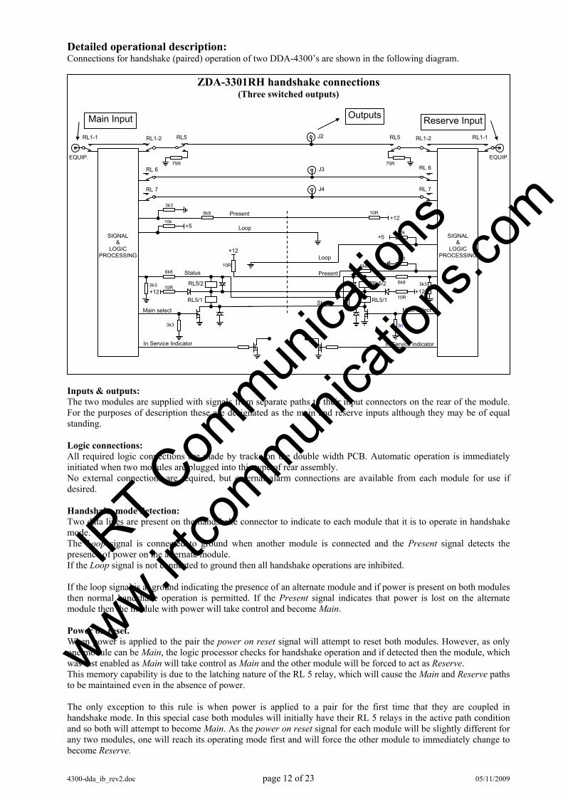
Detailed operational description: Connections for handshake (paired) operation of two DDA-4300’s are shown in the following diagram.
Inputs & outputs: The two modules are supplied with signals from separate paths to their input connectors on the rear of the module. For the purposes of description these are designated as the main and reserve inputs although they may be of equal standing. Logic connections: All required logic connections are made by tracks on the double width PCB. Automatic operation is immediately initiated when two modules are plugged into this type of rear assembly. No external connections are required, but external alarm connections are available from each module for use if desired. Handshake mode detection: Two data lines are present on the handshake connector to indicate to each module that it is to operate in handshake mode. The Loop signal is connected to ground when another module is connected and the Present signal detects the presence of power on the alternate module. If the Loop signal is not connected to ground then all handshake operations are inhibited. If the loop signal is at ground indicating the presence of an alternate module and if power is present on both modules then normal handshake operation is permitted. If the Present signal indicates that power is lost on the alternate module then the module with power will take control and become Main. Power on reset. When power is applied to the pair the power on reset signal will attempt to reset both modules. However, as only one module can be Main, the logic processor checks for handshake operation and if detected then the module, which was last enabled as Main will take control as Main and the other module will be forced to act as Reserve. This memory capability is due to the latching nature of the RL 5 relay, which will cause the Main and Reserve paths to be maintained even in the absence of power. The only exception to this rule is when power is applied to a pair for the first time that they are coupled in handshake mode. In this special case both modules will initially have their RL 5 relays in the active path condition and so both will attempt to become Main. As the power on reset signal for each module will be slightly different for any two modules, one will reach its operating mode first and will force the other module to immediately change to become Reserve.
ZDA-3301RH handshake connections (Three switched outputs)
Present6k8
SIGNAL &
LOGIC PROCESSING
3k3
+5
+12
Present
Loop
Status
Main select
3k3
3k36k8
+12
10k
10RRL5/2
RL5/1
10R
RL1-1
EQUIP.
6k8
SIGNAL &
LOGIC PROCESSING
3k3 +12
StatusMain select
In
3k3
+5
Loop
10k
10R
RL5/2
RL5/1
+12 10R
RL1-1
EQUIP.
RL 6 RL 6
J4
6k8
Main Input Reserve InputOutputs
RL1-2
75R
RL5 RL1-2 J2
75R
RL5
J3
In Service Indicator In Service Indicator
RL 7 RL 7
IRT C
ommun
icatio
ns
www.irtco
mmunica
tions
.com

4300-dda_ib_rev2.doc page 13 of 23 05/11/2009
As the selection of which module becomes Main cannot be determined before installation it may be necessary to force the desired module to become Main by pressing the Change Request button on the front panel of the desired module. The Main module will be indicated by the In Service LED, on the front panel, lighting. Automatic changeover: An automatic changeover is initiated whenever the power fails on Main and not on Reserve or when a general alarm is initiated on Main (indicating either loss of input signal or AIS indication if the AIS is enabled) and the Change Inhibit switch is not active on either module. In either case, the Main Status line will go from LO to HI. The companion module, on detecting this change, will switch its Main Select line to HI. The RL 5/1 relay driver then activates the relay (hence becoming Main) and sends the Status line to the first module LO confirming the change and preventing that module from attempting to become Main again. Manual changeover: A manual changeover is initiated by pressing the Change Request button on the front of the module that is required to become Main. The mechanism of the change is similar to the automatic changeover described above except that it is initiated by the module requesting that it become Main. This forces the Status line to the other module to LO and it immediately responds to become Reserve. Alarm and external changeover connections: Two Krone type connectors are provided on the rear panel providing the following for each of the modules:
Pin 1 RL 2 relay status - connection to ground indicates module is in bypass mode (loss of power).
2 RL 4 relay status - connection to ground indicates a general signal alarm. 3 External changeover request – connection to ground will make this module Main in
handshake mode. 4 Ground.
A third Krone type connector (SK3) (if fitted) provides remote status of which unit is In Service (Main):
Pin 1 Connection to ground indicates that module 1 is the In Service (Main) module. 2 Connection to ground indicates that module 2 is the In Service (Main) module. 3 Ground.
Direct and Shaped Links: In the DS3 G.703 specification, the output wave shape is not a square wave but has a shaped output that fits within a specified mask. The DDA-4300 does have shaped outputs so when the ZDA-4300RH is used with the DDA-4300’s then the links on the ZDA-4300RH marked Direct should be installed. On the older version DDA-3300 cards the outputs were unshaped, that is square waved. If the ZDA-4300RH is to be used with DDA-3300’s as opposed to DDA-4300’s then links marked Shaped on the ZDA-4300RH can be installed, instead of the Direct links, if problems occur connecting to equipment expecting to see a shaped signal. This would generally only be a problem for older style equipment. The ZDA-4300RH comes standard with the Direct links installed, unless otherwise ordered.
IRT C
ommun
icatio
ns
www.irtco
mmunica
tions
.com
4300-dda_ib_rev2.doc page 14 of 23 05/11/2009
Pre-installation: Handling: This equipment may contain or be connected to static sensitive devices and proper static free handling precautions should be observed. Where individual circuit cards are stored, they should be placed in antistatic bags. Proper antistatic procedures should be followed when inserting or removing cards from these bags. Power: AC mains supply: Ensure that operating voltage of unit and local supply voltage match and that correct
rating fuse is installed for local supply. DC supply: Ensure that the correct polarity is observed and that DC supply voltage is maintained
within the operating range specified. Earthing: The earth path is dependent on the type of frame selected. In every case particular care should be taken to ensure that the frame is connected to earth for safety reasons. See frame manual for details. Signal earth: For safety reasons a connection is made between signal earth and chassis earth. No attempt should be made to break this connection.
Operational Safety:
WARNING
Operation of electronic equipment involves the use of voltages and currents that may be dangerous to human life. Note that under certain conditions dangerous potentials may exist in some circuits when power controls are in the OFF position. Maintenance personnel should observe all safety regulations. Do not make any adjustments inside equipment with power ON unless proper precautions are observed. All internal adjustments should only be made by suitably qualified personnel. All operational adjustments are available externally without the need for removing covers or use of extender cards.
IR
T Com
munica
tions
www.irtco
mmunica
tions
.com
4300-dda_ib_rev2.doc page 15 of 23 05/11/2009
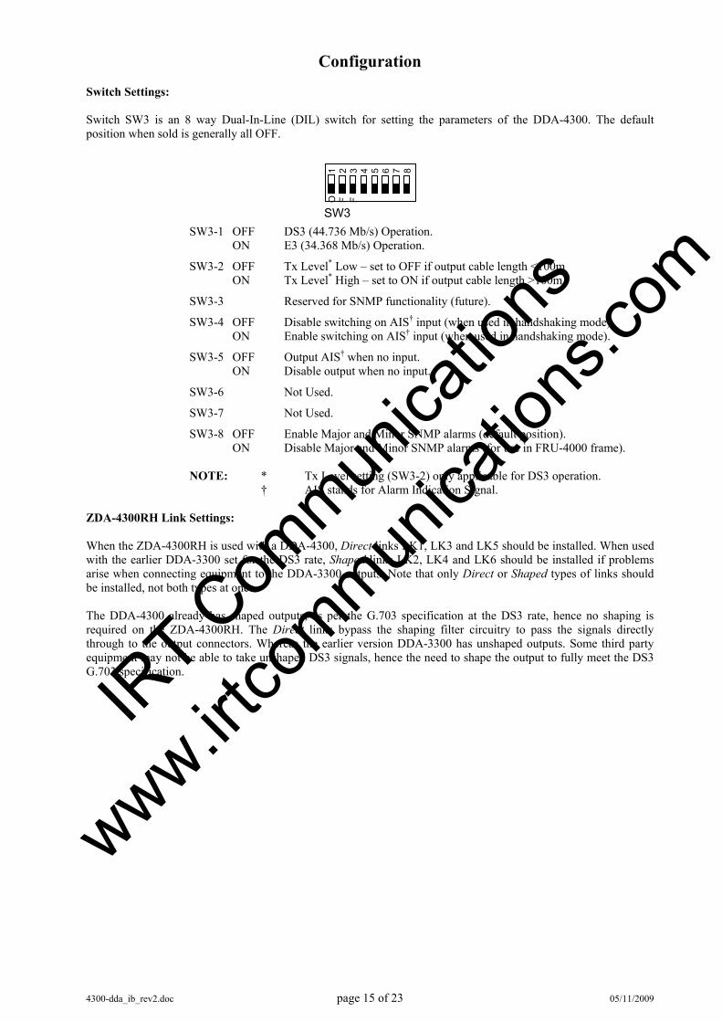
Configuration Switch Settings: Switch SW3 is an 8 way Dual-In-Line (DIL) switch for setting the parameters of the DDA-4300. The default position when sold is generally all OFF.
SW3-1 OFF DS3 (44.736 Mb/s) Operation. ON E3 (34.368 Mb/s) Operation.
SW3-2 OFF Tx Level* Low – set to OFF if output cable length <100m ON Tx Level* High – set to ON if output cable length >100m
SW3-3 Reserved for SNMP functionality (future).
SW3-4 OFF Disable switching on AIS† input (when used in handshaking mode). ON Enable switching on AIS† input (when used in handshaking mode).
SW3-5 OFF Output AIS† when no input. ON Disable output when no input.
SW3-6 Not Used.
SW3-7 Not Used.
SW3-8 OFF Enable Major and Minor SNMP alarms (default position). ON Disable Major and Minor SNMP alarms (for use in FRU-4000 frame).
NOTE: * Tx Level setting (SW3-2) only applicable for DS3 operation.
† AIS stands for Alarm Indication Signal. ZDA-4300RH Link Settings: When the ZDA-4300RH is used with a DDA-4300, Direct links LK1, LK3 and LK5 should be installed. When used with the earlier DDA-3300 set for the DS3 rate, Shaped links LK2, LK4 and LK6 should be installed if problems arise when connecting equipment to the DDA-3300 outputs. Note that only Direct or Shaped types of links should be installed, not both types at once. The DDA-4300 already has shaped outputs, as per the G.703 specification at the DS3 rate, hence no shaping is required on the ZDA-4300RH. The Direct links bypass the shaping filter circuitry to pass the signals directly through to the output connectors. Whereas the earlier version DDA-3300 has unshaped outputs. Some third party equipment may not be able to take unshaped DS3 signals, hence the need to shape the output to fully meet the DS3 G.703 specification.
SW3
O
1 F
2 F
3
4
5
6
7
8
IRT C
ommun
icatio
ns
www.irtco
mmunica
tions
.com
4300-dda_ib_rev2.doc page 16 of 23 05/11/2009
Installation Installation in frame or chassis: See details in separate manual for selected frame type. G.703 data connections – stand alone operation: For use with supplied standard rear assembly. Connect the input and as many output connections as required. Only good quality 75 Ohm connectors and cable should be used. The use of 50 Ohm BNC connectors may cause serious reflection problems with G.703 signals, causing data errors. In general cable runs should be kept as short as possible and should not exceed 200 metres for reliable error free operation. Stand-alone alarm connections: A Krone type connector is provided on the rear panel of the module providing the following:
Pin 1 Connection to ground indicates module is in bypass mode (loss of power). 2 Connection to ground indicates a general signal alarm. 3 External changeover request – for use in the handshake mode. Not used for stand-alone
operation. 4 Ground.
G.703 data connections - handshake operation: For use with ZDA-4300RH rear assembly. See separate section on handshake operation for detailed description of operation. The ZDA-4300RH is a double width rear assembly that takes the place of two standard rear assemblies that would normally be fitted side by side. The ZDA-4300RH supplies the necessary controls between the two main cards. Connect the two separate inputs and as many output connections as required. J2 corresponds to Output 1, J3 corresponds to Output 2, and J4 corresponds to Output 3. Only good quality 75 Ohm connectors and cable should be used. The use of 50 Ohm BNC connectors may cause serious reflection problems with G.703 signals, causing data errors. In general cable runs should be kept as short as possible and should not exceed 200 metres for reliable error free operation. Handshake alarm connections: Two Krone type connectors, 1SK2 and 2SK2, corresponding to each of the cards are provided on the rear panel of the module providing the following:
Pin 1 Connection to ground indicates module is in bypass mode (loss of power). 2 Connection to ground indicates a general signal alarm. 3 External changeover request – connection to ground will make this module Main in
handshake mode. 4 Ground.
A third Krone type connector (SK3) (if fitted) provides remote status of which unit is In Service (Main).
Pin 1 Connection to ground indicates that module 1 is the In Service (Main) module. 2 Connection to ground indicates that module 2 is the In Service (Main) module. 3 Ground.
IRT C
ommun
icatio
ns
www.irtco
mmunica
tions
.com
4300-dda_ib_rev2.doc page 17 of 23 05/11/2009
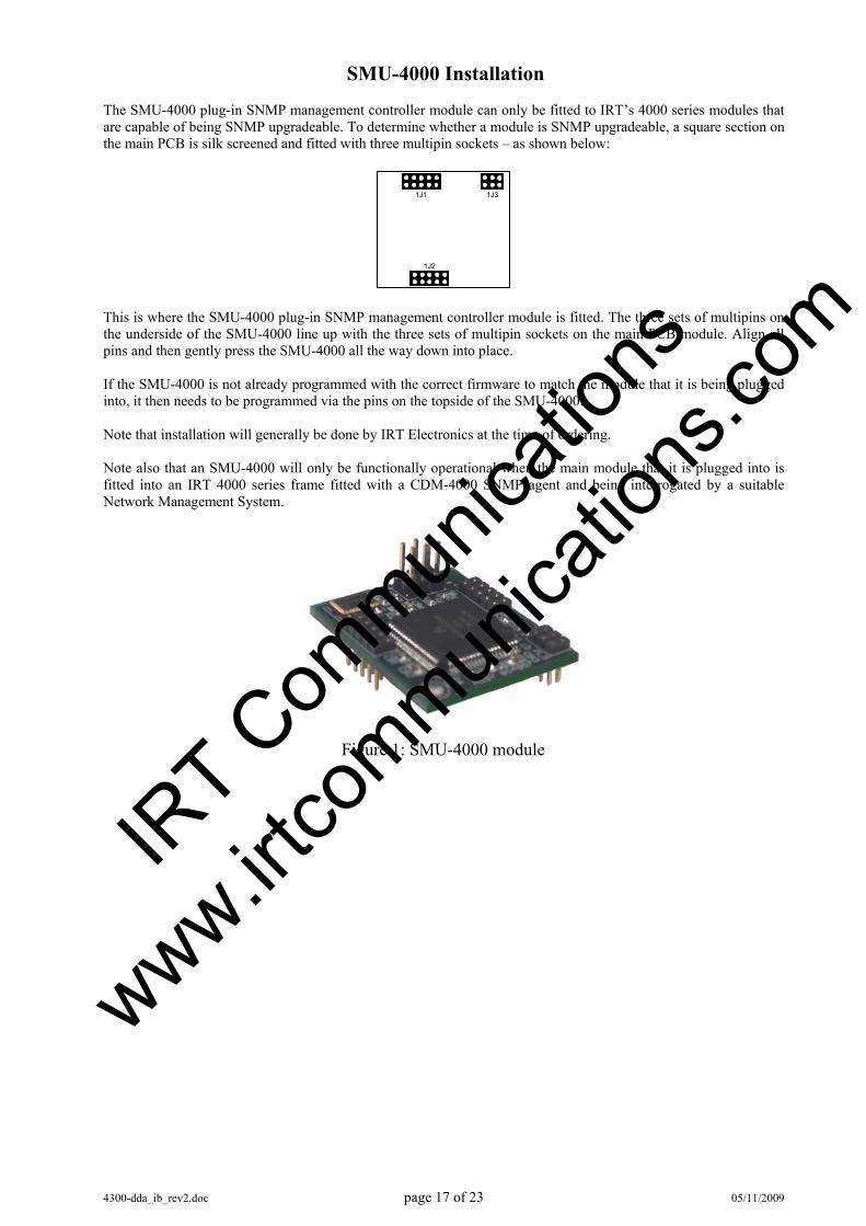
SMU-4000 Installation The SMU-4000 plug-in SNMP management controller module can only be fitted to IRT’s 4000 series modules that are capable of being SNMP upgradeable. To determine whether a module is SNMP upgradeable, a square section on the main PCB is silk screened and fitted with three multipin sockets – as shown below:
This is where the SMU-4000 plug-in SNMP management controller module is fitted. The three sets of multipins on the underside of the SMU-4000 line up with the three sets of multipin sockets on the main PCB module. Align all pins and then gently press the SMU-4000 all the way down into place. If the SMU-4000 is not already programmed with the correct firmware to match the module that it is being plugged into, it then needs to be programmed via the pins on the topside of the SMU-4000. Note that installation will generally be done by IRT Electronics at the time of ordering. Note also that an SMU-4000 will only be functionally operational when the main module that it is plugged into is fitted into an IRT 4000 series frame fitted with a CDM-4000 SNMP agent and being interrogated by a suitable Network Management System.
1J2
1J1 1J3
Figure 1: SMU-4000 module
IRT C
ommun
icatio
ns
www.irtco
mmunica
tions
.com

4300-dda_ib_rev2.doc page 18 of 23 05/11/2009
1
2
3
4
SK 6 INPUT
OUTPUT 1
OUTPUT 2
OUTPUT 3
SK 8
SK 9
SK 4
SK 5
PL4
PL5
Front & rear panel diagrams The following front panel and rear assembly drawings are not to scale and are intended to show relative positions of connectors, indicators and controls only.
ZDA-4300RH
1234
2SK 2
J 2
J 3
OUTPUTS
J 4
1 2 3 4
SK 3
1J 1
INPUT MODULE 2
INPUT MODULE 1
1SK 2 123
2J1
DIR
ECT
1P3
1P2
2P3
2P2
DIR
ECT
DIR
ECT
LK1
LK5
LK3
SHAPED
LK2
SHAPED
LK4
SHAPED
LK6
ALLOWINHIBIT
REQUEST
AIS
INPUT
CHANGE
MAIN
STBY
DDA-4300
N140
MON.
EQUIP.
LINE
cERR
ucERR
IRT C
ommun
icatio
ns
www.irtco
mmunica
tions
.com
4300-dda_ib_rev2.doc page 19 of 23 05/11/2009
Operation Stand-alone operation: When used in a stand-alone situation, that is non-hand shaking mode, the DDA-4300 behaves as a standard E3 or DS3 distribution amplifier, dependent upon the switch SW3 settings described in the Configuration section of this manual. One input is electronically split into three outputs. On loss of power to the unit the input is automatically bypassed to output 1 via on board relays. A loss of power alarm and general alarm (loss of signal, AIS detect) is provided by relay contacts to ground via the Krone connector on the rear assembly, see Installation section of this manual for connections. Front panel LEDs indicate the presence of a valid input signal (In Service – green), the absence of a valid input signal (Data Loss – Red) and the detection of an alarm indication signal within the inputted signal (AIS – Red). The Standby LED (orange) is not used in the stand-alone operation. The front panel change switches do not work when used in a stand-alone operation. Handshake operation: When used in the handshake mode, two cards (both set for either E3 or DS3 operation) fit side by side plugged into a ZDA-4300RH. The ZDA-4300RH provides the necessary interconnect controls to automatically switch between the input signals to the outputs, provided that the toggle switch on the front panels of the units are set to Change Allow and not Change Inhibit. Automatic switching parameters are set by a loss of input condition and switch SW3 settings as described in the Configuration section of this manual. When the toggle switch is set to Change-Inhibit both automatic and manual switching of the input signals is not possible. When the units are first turned on one unit will take the responsibility of being In Service (Main) whilst the other will become the Standby unit. It may be necessary to manually swap the two states if they do not start in the required configuration by pressing the front panel manual switch on the unit that is desired to be acting as the In Service module. Note that in order to do so the toggle switch should also be set to the Change-Allow position on both modules. Loss of power alarms and general (loss of signal, AIS detect) alarms are provided by relay contacts to ground via the Krone connectors on the rear assembly. Module In Service tally is also provided via these same Krone connectors, see Installation section of this manual for connections. Front panel LEDs, on both units, indicate the presence of a valid input signal (In Service – green, or Standby - orange ), the absence of a valid input signal (Data Loss – Red) and the detection of an alarm indication signal within the inputted signal (AIS – Red). IR
T Com
munica
tions
www.irtco
mmunica
tions
.com
4300-dda_ib_rev2.doc page 20 of 23 05/11/2009
SNMP
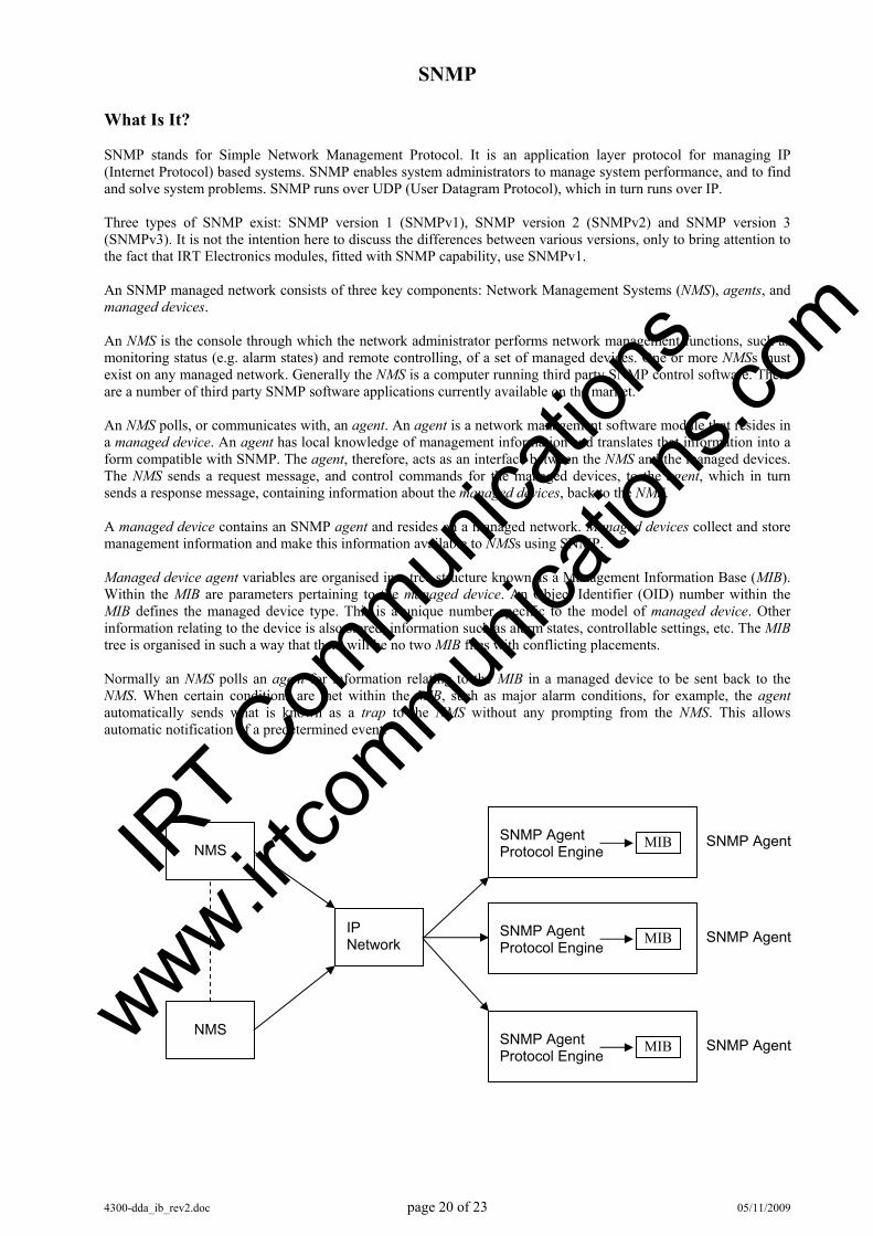
What Is It? SNMP stands for Simple Network Management Protocol. It is an application layer protocol for managing IP (Internet Protocol) based systems. SNMP enables system administrators to manage system performance, and to find and solve system problems. SNMP runs over UDP (User Datagram Protocol), which in turn runs over IP. Three types of SNMP exist: SNMP version 1 (SNMPv1), SNMP version 2 (SNMPv2) and SNMP version 3 (SNMPv3). It is not the intention here to discuss the differences between various versions, only to bring attention to the fact that IRT Electronics modules, fitted with SNMP capability, use SNMPv1. An SNMP managed network consists of three key components: Network Management Systems (NMS), agents, and managed devices. An NMS is the console through which the network administrator performs network management functions, such as monitoring status (e.g. alarm states) and remote controlling, of a set of managed devices. One or more NMSs must exist on any managed network. Generally the NMS is a computer running third party SNMP control software. There are a number of third party SNMP software applications currently available on the market. An NMS polls, or communicates with, an agent. An agent is a network management software module that resides in a managed device. An agent has local knowledge of management information and translates that information into a form compatible with SNMP. The agent, therefore, acts as an interface between the NMS and the managed devices. The NMS sends a request message, and control commands for the managed devices, to the agent, which in turn sends a response message, containing information about the managed devices, back to the NMS. A managed device contains an SNMP agent and resides on a managed network. Managed devices collect and store management information and make this information available to NMSs using SNMP. Managed device agent variables are organised in a tree structure known as a Management Information Base (MIB). Within the MIB are parameters pertaining to the managed device. An Object Identifier (OID) number within the MIB defines the managed device type. This is a unique number specific to the model of managed device. Other information relating to the device is also stored, information such as alarm states, controllable settings, etc. The MIB tree is organised in such a way that there will be no two MIB files with conflicting placements. Normally an NMS polls an agent for information relating to the MIB in a managed device to be sent back to the NMS. When certain conditions are met within the MIB, such as major alarm conditions, for example, the agent automatically sends what is known as a trap to the NMS without any prompting from the NMS. This allows automatic notification of a predetermined event.
NMS
NMS
IP Network
MIB SNMP Agent Protocol Engine
SNMP Agent
MIB SNMP Agent Protocol Engine
SNMP Agent
MIB SNMP Agent Protocol Engine
SNMP Agent
IRT C
ommun
icatio
ns
www.irtco
mmunica
tions
.com
4300-dda_ib_rev2.doc page 21 of 23 05/11/2009
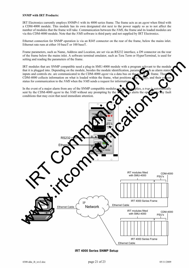
SNMP with IRT Products: IRT Electronics currently employs SNMPv1 with its 4000 series frame. The frame acts as an agent when fitted with a CDM-4000 module. This module has its own designated slot next to the power supply so as to not affect the number of modules that the frame will take. Communication between the NMS, the frame and its loaded modules are via this CDM-4000 module. Note that the NMS software is third party and not supplied by IRT Electronics. Ethernet connection for SNMP operation is via an RJ45 connector on the rear of the frame, below the mains inlet. Ethernet rate runs at either 10 baseT or 100 baseT. Frame parameters, such as Name, Address and Location, are set via an RS232 interface, a D9 connector on the rear of the frame below the mains inlet. A software terminal emulator, such as Tera Term or HyperTerminal, is used for setting and reading the parameters of the frame. IRT modules that are SNMP compatible need a plug-in SMU-4000 module with a program relevant to the module that it is plugged into. Depending on the module, besides the module identification, parameters such as alarm states, inputs and controls etc. are communicated to the CDM-4000 agent via a data bus on the rear of the frame. Thus the CDM-4000 collects information on what is loaded within the frame, what positions they occupy, and their current status for communication to the NMS when the NMS sends a request for information. In the event of a major alarm from any of the SNMP compatible modules, or power supplies, a trap is automatically sent by the CDM-4000 agent to the NMS without any prompting by the NMS. This alerts the operator to any fault conditions that may exist that need immediate attention.
FRU-4000FRAME110/240 V 50/60 Hz
0.7 A (max.)
FUSES
110/120 Vac1A S.B.
220/240 Vac500 mA S.B.
AS3260 approval no.: CS6346NAss. no.: 804692
+ -48Vdc
AlarmRS232
Ethernet
IRT modules fitted with SMU-4000 PSU’s
CDM-4000
IRT 4000 Series Frame
IRT 4000 Series Frame
IRT modules fitted with SMU-4000 PSU’s
CDM-4000
IP Network Ethernet Cable
Ethernet Cable
Ethernet Cable NMS
IRT 4000 Series SNMP Setup
IRT C
ommun
icatio
ns
www.irtco
mmunica
tions
.com
4300-dda_ib_rev2.doc page 22 of 23 05/11/2009
DDA-4300 SNMP Functions:
With the DDA-4300 fitted with the optional plug-in SMU-4000 SNMP module, programmed with firmware to suit, and installed in an IRT 4000 series frame with SNMP capability, the DDA-4300 can be interrogated by an SNMP Network Management System (NMS).
The following SNMP functions are capable of being monitored by an NMS:
An indication of the data rate to which the module has been configured – E3 or DS3; An indication of the status of the G.703 input signal – Not Present, Present, Framed, AIS detected; An indication if the module is acting as the Main (In Service) or Standby; Set the module as Main, provided that “change” is not inhibited by the front panel switch setting; An indication if a change from Main to Standby, or vice versa is allowed when part of a redundant pair; An indication if a change from Main to Standby will be initiated upon detection of AIS; An indication of the set output level from the module (high or low) if the data rate has been set to DS3; An indication if the other module of a redundant pair is present; An indication if an ASI signal has been detected in the payload; An indication whether the number of bytes in the detected ASI packet is 188, 204, or indeterminate; An indication if Reed Solomon Error correction data has been detected in the ASI packet; An indication of the number of errors detected using the RS data since the counter was last reset; The software version of the FPGA; Whether “Trap” function is enabled; Trap automatically sent, if enabled, on loss of input signal; Trap automatically sent, if enabled, on change of module status; and Unit reset control.
IRT C
ommun
icatio
ns
www.irtco
mmunica
tions
.com

4300-dda_ib_rev2.doc page 23 of 23 05/11/2009
Maintenance & Storage Maintenance: No regular maintenance is required. Care however should be taken to ensure that all connectors are kept clean and free from contamination of any kind. This is especially important in fibre optic equipment where cleanliness of optical connections is critical to performance. Storage: If the equipment is not to be used for an extended period, it is recommended the whole unit be placed in a sealed plastic bag to prevent dust contamination. In areas of high humidity a suitably sized bag of silica gel should be included to deter corrosion. Where individual circuit cards are stored, they should be placed in antistatic bags. Proper antistatic procedures should be followed when inserting or removing cards from these bags.
Warranty & Service Equipment is covered by a limited warranty period of three years from date of first delivery unless contrary conditions apply under a particular contract of supply. For situations when “No Fault Found” for repairs, a minimum charge of 1 hour’s labour, at IRT’s current labour charge rate, will apply, whether the equipment is within the warranty period or not. Equipment warranty is limited to faults attributable to defects in original design or manufacture. Warranty on components shall be extended by IRT only to the extent obtainable from the component supplier. Equipment return: Before arranging service, ensure that the fault is in the unit to be serviced and not in associated equipment. If possible, confirm this by substitution. Before returning equipment contact should be made with IRT or your local agent to determine whether the equipment can be serviced in the field or should be returned for repair. The equipment should be properly packed for return observing antistatic procedures. The following information should accompany the unit to be returned:
1. A fault report should be included indicating the nature of the fault 2. The operating conditions under which the fault initially occurred. 3. Any additional information, which may be of assistance in fault location and remedy. 4. A contact name and telephone and fax numbers. 5. Details of payment method for items not covered by warranty. 6. Full return address. 7. For situations when “No Fault Found” for repairs, a minimum charge of 1 hour’s labour will apply,
whether the equipment is within the warranty period or not. Contact IRT for current hourly rate. Please note that all freight charges are the responsibility of the customer. The equipment should be returned to the agent who originally supplied the equipment or, where this is not possible, to IRT direct as follows.
Equipment Service IRT Electronics Pty Ltd 26 Hotham Parade ARTARMON N.S.W. 2064 AUSTRALIA Phone: 61 2 9439 3744 Fax: 61 2 9439 7439 Email: [email protected]
IRT C
ommun
icatio
ns
www.irtco
mmunica
tions
.com