DCDC Air Circuit Breakers Moulded Case Circuit ... - Terasaki TemBreak 2 Terasaki DC...
108
www.terasaki.co.jp CAT REF. ’17-I73E Air Circuit Breakers Moulded Case Circuit Breakers & Air Circuit Breakers Moulded Case Circuit Breakers DC DC DC
Transcript of DCDC Air Circuit Breakers Moulded Case Circuit ... - Terasaki TemBreak 2 Terasaki DC...

www.terasaki.co.jp
CAT REF. ’17-I73E
Air Circuit Breakers Moulded Case Circuit Breakers
&
Air Circuit Breakers Moulded Case Circuit BreakersDCDCDC

TABLE OF CONTENTS
Introduction ……………………………………………1-2General …………………………………………………1-3Selection Chart …………………………………………1-4
Air Circuit Breakers for DC350V-800V ………………2-2Moulded Case Circuit Breakers for DC350V-600V …2-3Moulded Case Circuit Breakers for DC750V-1000V…2-5Switch-disconnectors for DC600V-1000V ……………2-8
Time/Current characteristic curves, Ambient Compensating Curves
S160-SD, S160-GD, PVE160-SDL, S250-SD, S250-GD 3P ……………3-2
S400-ND, S800-ND 3P………………………………3-3S1000-ND 2P, 3P ……………………………………3-3XS1250ND, XS1600ND, XS2000ND 2P, 3P ………3-4XS2500ND, XS3200ND 2P, 3P ……………………3-5PVS160-SDL, PVS250-SDL 3P, 4P ………………3-6PVS160-SDH, PVS250-SDH 4P……………………3-6PVS160-GDH, PVS250-GDH 4P……………………3-6PVS400-NDL 3P ……………………………………3-6PVS400-NDL, PVS400-NDH, PVS800-NDH 4P …3-7PVS800-NDL 3P, 4P…………………………………3-7
Connection of conductors to DC circuit breakers …4-2Insulation distance DC600V or less …………………4-7Insulation distance DC750V-1000V
PVE160-SDL 3P ……………………………………4-8PVS160-SDL 3P,
PVS250-SDL 3P, PVS250-SNL 3P ………4-9PVS160-SDL 4P, PVS250-SDL 4P,
PVS160-SNL 4P, PVS250-SNL 4P ……4-10PVS160-GDH 4P, PVS250-GDH 4P………………4-11PVS160-SDH 4P, PVS250-SDH 4P ………………4-12PVS160-SNH 4P, PVS250-SNH 4P ………………4-13PVS400-NDL 3P ……………………………………4-14PVS400-NDL 4P, PVS400-NDH 4P ………………4-15PVS400-NNL 3P ……………………………………4-16PVS400-NNL 4P, PVS400-NNH 4P ………………4-17PVS800-NDL 3P ……………………………………4-18PVS800-NDL 4P, PVS800-NDH 4P ………………4-19PVS800-NNL 3P ……………………………………4-20PVS800-NNL 4P, PVS800-NNH 4P ………………4-21
Internally mounted accessories1. Connection diagrams and terminal numbers …5-22. Possible combinations……………………………5-33. Ratings data of auxiliary and alarm switches …5-44. Shunt trip device (SH) ……………………………5-45. Undervoltage trip device (UV) …………………5-4
Externally mounted accessories1. Motor operators (MC) ……………………………5-62. External operating handles ……………………5-12
(1) Breaker-mounted(field installable small type) (HB)……5-12
(2) Door-mounted (depth adjustable) (HP)……5-203. Toggle holder (HH) and toggle lock (HL) ……5-274. Terminal covers …………………………………5-285. Terminal blocks (TF) ……………………………5-32
DC Air Circuit Breakers Outline DimensionsAR216S, AR220S 3P…………………………………6-2AR325S, AR332S 3P…………………………………6-4AR325-NDH 4P ………………………………………6-6AR440S 3P……………………………………………6-8
DC Moulded Case Circuit Breakers Outline DimensionsS160-SD, S160-GD, S160-SDN, S250-SD,
S250-GD, S250-SDN 3P ………………6-10S400-ND 3P…………………………………………6-11S800-ND 3P…………………………………………6-11S1000-ND 2P, 3P……………………………………6-12XS1250ND 2P, 3P …………………………………6-13XS1600ND 2P, 3P …………………………………6-14XS2000ND 2P, 3P …………………………………6-15XS2500ND, XS3200ND 2P, 3P ……………………6-16PVE160-SDL 3P ……………………………………6-17PVS160-SDL, PVS250-SDL 3P……………………6-18PVS250-SNL 3P ……………………………………6-18PVS160-SDL, PVS250-SDL,
PVS160-SNL, PVS250-SNL 4P…………6-19PVS160-GDH, PVS250-GDH 4P …………………6-19PVS160-SDH, PVS250-SDH,
PVS160-SNH, PVS250-SNH 4P ………6-20PVS400-NDL 3P ……………………………………6-21PVS400-NDL, PVS400-NDH 4P …………………6-21PVS400-NNL 3P ……………………………………6-22PVS400-NNL, PVS400-NNH 4P …………………6-22PVS800-NDL 3P ……………………………………6-23PVS800-NDL, PVS800-NDH 4P …………………6-23PVS800-NNL 3P ……………………………………6-24PVS800-NNL, PVS800-NNH 4P …………………6-24
6.Outline Dimensions …………………………6-1
5.Accessories …………………………………5-1
4.Mounting and Connection…………………4-1
3.Characteristics ………………………………3-1
2.Ratings and Specifications ………………2-1
1.General ………………………………………1-1
TABLE OF CONTENTS

1-1
1
Gen
eral1Introduction ………………………………………………………………………1-2General ……………………………………………………………………………1-3Selection Chart …………………………………………………………………1-4
General

1-2
Introduction
In recent years, as part of the drive to reduce greenhouse gas emissions, significant attention is now
being directed towards the energy produced by large-scale photovoltaic (solar), wind, and biomass
energy power generation.
The total power generation capacity of facilities for these new energy sources is expected to exceed that
produced by nuclear energy by approximately 2030. To aid and support these new technologies,
Terasaki now offer a new, broad range of dedicated DC air circuit breakers and moulded case circuit
breakers. The new range of Terasaki DC circuit breakers are ideally suited for all types of industries,
buildings, as well as the information technology and communications sectors where highly reliable
sources of electric power are required.
Introduction
Possible reverse connection
DC Air Circuit Breakers
AR220SRated current 2000A
Rated breaking capacity DC600V 40kA
Possible reverse connection
DC Moulded Case Circuit Breakers
PVE160-SDLRated current 160A
Rated breaking capacity DC750V 3kA
Possible reverse connection
PVS160-SDLRated current 160A
Rated breaking capacity DC750V 5kA
Possible reverse connection
PVS250-SDHRated current 250A
Rated breaking capacity DC1000V 5kA

1-3
1
Gen
eral
GeneralGeneral
DC power sources for the Uninterruptible Power Supply (UPS) market
Electrical and electronic equipment used in the advanced information and communications sectors requires a
highly reliable power source. Should a power failure occur, and to assist with continuity of electrical power, it is
standard practice to install an Uninterruptable Power Supply (UPS).
A data centre is where Internet servers and other systems for data communications, such as fixed, mobile, and IP
telephones are installed. At the data centre, AC power from the main system power source is sent to the UPS,
and is temporarily converted to DC power. A storage battery is then charged with this DC power, which is re-
converted back into AC power and then sent to the information equipment.
Photovoltaic power generation
Photovoltaic (or Solar) power generation, which is attracting attention as clean energy, ranges from simple
generation of up to several kilowatts for home use, to larger systems of 100 kilowatts or greater for industrial use.
In the "School New Deal" program, one of the governmental measures during the economic crisis, were for eco-
friendly modifications which advocated the use of photovoltaic power generation at schools. One example is a
power distribution system linked to a source of photovoltaic power generation. The current produced from the
photovoltaic solar cells is sent to a power conditioner via a diode with a DC circuit breaker in a junction box and
then converted into AC, which can then be supplied to a load via a distribution board.
Building and Industrial power back-up
A UPS is typically required for critical power systems in department stores, hotels, hospitals, theaters, and office
buildings. For example, in semiconductor manufacturing plants that feature advanced automation as a part of
their production processes, UPS systems with large battery capacities are used to take measures against any
large-scale power outage affecting critical manufacturing facilities.
Rationalization of use of electric power via large-capacity storage battery
Energy from new power sources such as wind and photovoltaic power generation do not have a stable output. A
lithium ion battery and a sodium-sulfur (NAS) battery can suppress such fluctuations by load leveling. The battery
is charged at night using a lower electrical power rate at night and discharged at daytime when the electrical
power usage rate is higher, and in addition, any new electrical power generated can also be saved. For this
purpose, large-capacity storage battery systems are used at wind and photovoltaic power generation facilities.
The use of these types of systems is expected to grow across all user sectors requiring large amounts of power,
plus as an additional measure against possible power outages.

1-4
800
800V
600V
1000V
750V
600V
500V
350V
250V
1000V
800V
Selection ChartFrame size (A)
400
600V
PVS800-NDH4P
5kA/5kA
PVS800-NDL3P
10kA/10kA
S800-ND3P
20kA/10kA
PVS400-NDH4P
5kA/5kA
PVS400-NDL3P
10kA/5kA
PVS800-NDL4P
10kA/10kA
PVS400-NDL4P
10kA/10kA
S400-ND3P
15kA/15kA
S800-ND3P
30kA/15kA
PVS800-NNH4P
PVS800-NNL4P
S400-ND3P
20kA/20kA
PVS400-NNH4P
PVS400-NNL4P
PVS250-SNL4P
Air Circuit Breakers
Moulded Case CircuitBreakers
Switch-disconnectors
Voltage160 250
S250-GD3P
10kA/5kA
PVS250-SDH4P
5kA/5kA
PVS250-SDL3P
10kA/5kA
PVS250-SDL4P
10kA/5kA
S250-GD3P
15kA/7.5kA
S160-GD3P
10kA/5kA
PVS160-SDH4P
5kA/5kA
PVS250-GDH4P
10kA/5kA
PVS160-GDH4P
10kA/5kA
PVS160-SDL3P
10kA/5kA
PVE160-SDL3P
3kA/3kA
PVS160-SDL4P
10kA/5kA
S160-GD3P
15kA/7.5kA
S250-SD3P
5kA/5kA
S250-SD3P
7.5kA/7.5kA
S250-SD3P
10kA/10kA
S160-SD3P
5kA/5kA
S160-SD3P
7.5kA/7.5kA
S160-SD3P
10kA/10kA
PVS160-SNL4P
750VPVS800-NNL
3PPVS400-NNL
3PPVS250-SNL
3P
PVS250-SNH4P
PVS160-SNH4P
S160-SDN3P
S250-SDN3P
All Air Circuit Breakers and Switch-disconnectors are possible to reverse the connection.
Moulded Case Circuit Breakers up to 1000A frame are possible to reverse the connection.

1-5
1
Gen
eral
320025002000160012501000
AR325-NDH4P
30kA/30kA
AR325S3P
40kA/40kA
AR220S3P
40kA/40kA
AR216S3P
40kA/40kA
AR332S3P
40kA/40kA
4000
AR440S3P
40kA/40kA
S1000-ND3P
20kA/10kA
S1000-ND3P
30kA/15kA
S1000-ND2P
50kA/20kA
XS1250ND3P
20kA/15kA
XS1250ND3P
50kA/25kA
XS1250ND2P
50kA/30kA
XS1600ND3P
20kA/15kA
XS1600ND3P
50kA/25kA
XS1600ND2P
50kA/30kA
XS2000ND3P
20kA/15kA
XS2000ND3P
50kA/25kA
XS2000ND2P
50kA/30kA
XS2500ND3P
20kA/15kA
XS2500ND3P
50kA/25kA
XS2500ND2P
50kA/30kA
XS3200ND3P
20kA/15kA
XS3200ND3P
50kA/25kA
XS3200ND2P
50kA/30kA
S160-SD3P
5kA/5kA
IcsIcu
Number of polesReverse connection
Not possible
Reverse connection
Possible


2-1
2
Ratin
gs
and
Sp
ecification
s
2Air Circuit Breakers for DC350V-800V ………………………………………2-2Moulded Case Circuit Breakers for DC350V-600V…………………………2-3Moulded Case Circuit Breakers for DC750V-1000V ………………………2-5Switch-disconnectors for DC600V-1000V …………………………………2-8
Ratings andSpecifications
2-2
Air Circuit Breakers for DC350V-800V
Frame size (A)
Type Rated current(max.)〔In〕ANumber of polesRated insulation voltage〔Ui〕 V ACRated operational voltage〔Ue〕 V DCRated impulse withstand voltage〔U imp〕 kV■Rated breaking cap, kAJIS C 8201-2-1 Ann.1 Ann.2 DC 800VIEC 60947-2 600VIcu/Ics①② 500V
350VRated short time withstand current〔Icw〕 kA 1sLatching current kATotal breaking time (s)■Closing operation timeSpring charging time (s) max.Close time (s) max.■No. of operating cyclesMechanical life with maintenance
without maintenanceElectrical life without maintenance DC 600V■Outline dimension mmDraw-out atype b
cd
Weight kgReverse connection
1600AR216S16003100060012
―40/4040/4040/4040650.04
100.08
30000150001000
3544603454076Yes
2000AR220S20003100060012
―40/4040/4040/4040650.04
100.08
25000120001000
3544603454079Yes
2500AR325S25003100060012
―40/4040/4040/4040850.04
100.08
2000010000500
46046034540105Yes
2500AR325-NDH25004100080012
30/30―――30850.04
100.08
2000010000500
58046034540125Yes
3200AR332S32003100060012
―40/4040/4040/4040850.04
100.08
2000010000500
46046034540105Yes
4000AR440S40003100060012
―40/4040/4040/40401000.04
100.08
150008000500
63146037553139Yes
Notes:― : “no” or “not available”. ① : AGR over-current release can not be used for DC. Please prepare DC over-current relay and connect with shunt trip device.② : The time constant (L/R) of the circuit should be,
less than 2.0ms nearby rated currentless than 15ms for short circuit
(1)Shunt trip device is Instantaneously rated type. Continuously rated shunt trip device is not applicable.(2)Undervoltage trip device is not applicable.(3)Test jumper is not applicable.For further details please contact TERASAKI.
a c d
b

2-3
Moulded Case Circuit Breakers for DC350V-600V
2
Ratin
gs
and
Sp
ecification
s
Frame size (A)
Type Number of poles■RatingsRated current, ACalibrated at 45°C
*2 poles breaker is same outline dimensions as 3 poles breaker.
Rated insulation voltage〔Ui〕 V Rated impulse withstand voltage 〔U imp〕 kV■Rated breaking capacity, kAJIS C 8201-2-1 Ann.1 Ann.2 DC 600VIEC 60947-2 500VIcu/Ics④⑤ 350V
250V■External dimensions, mm
abcd
Weight (' marked standard type) kg■Connections and MountingsFront-connected (FC) Terminal screws
With extension barsRear-connected (RC) Flat bar studsPlug-in (PM) For switchboards
For distribution boardsDraw-out type (DR)TemPlug70 (PG)TemPlug45B (PG4)DIN rail mountClip-in chassis mount■Accessories (optional) Symbol
Auxiliary switch AXAlarm switch ALShunt trips SHUndervoltage trips UVMotor operator MCExternal operating Breaker-mounted HBhandle Door-mounted (variable depth) HPToggle extension HAMechanical interlock Slide type MS
Rear-connected type MBLink type MLWire type MW
Toggle holder HHToggle lock HLTerminal cover For front-connected CF
For rear-connected and plug-in CRInterpole barrier BATerminal block for lead TFDoor flange DF
■Standard specificationsOvercurrent trip mechanism
Colour of coverTrip button (Colour)Handle position indication (ON: Red, OFF: Green)Suitability for isolationReverse connection
160S160-SD3
25 (16-25)32 (20-32)40 (25-40)63 (40-63)80 (50-80)100 (63-100)125 (80-125)160 (100-160)6908
5/57.5/7.510/10―
75130+50⑰68950.8
'
○(BAR)○―――――○⑪―
●●●●―●●―――――●●●⑫●⑫●⑬●●
Adj. thermal,fixed magneticGreyYes (Red)YesYesYes
160S160-GD3
25 (16-25)32 (20-32)40 (25-40)63 (40-63)80 (50-80)100 (63-100)125 (80-125)160 (100-160)6908
10/515/7.5――
75130+50⑰68950.8
'
○(BAR)○―――――○⑪―
●●●●―●●―――――●●●⑫●⑫●⑬●●
Adj. thermal,fixed magneticGreyYes (Red)YesYesYes
250S250-GD3
100 (63-100)125 (80-125)160 (100-160)200 (125-200)250 (160-250)
8008
10/515/7.5――
105165+55⑰68951.5
'
○(BAR)○―――――――
●●●●●●●―――――●●●⑫●⑫●⑬●●
Adj. thermal,fixed magneticGreyYes (Red)YesYesYes
250S250-SD3
100 (63-100)125 (80-125)160 (100-160)200 (125-200)250 (160-250)
8008
5/57.5/7.510/10―
105165+55⑰68951.5
'
○(BAR)○―――――――
●●●●●●●―――――●●●⑫●⑫●⑬●●
Adj. thermal,fixed magneticGreyYes (Red)YesYesYes
400S400-ND3
250 (160-250)400 (250-400)
8008
15/1515/1520/20―
1402601031454.2
'
○(BAR)○―――――――
●●●●●●●―――――
●
●●●③●●
Adj. thermal,fixed magneticGreyYes (Red)YesYesYes
800S800-ND3
630 (400-630)800 (500-800)
8008
20/1020/1030/15―
2102731031458.5
―'
○―――――――
●●●●●●●●――――
●
●●●③●●
Adj. thermal,fixed magneticGreyYes (Red)YesYesYes
1000S1000-ND2* 3
1000
8008
― 20/10― 20/10― 30/1550/20 ―
2102731031459.8 10.8
―'
○―――――――
●●●●●●●●――――
●
●●●③●●
Fixed thermal,fixed magneticGreyYes (Red)YesYesYes
a
b
cd
Notes:' : Standard. This configuration used unless otherwise specified. ○ : Optional standard. Specify when ordering. ● : “yes” or “available”. ― : “no” or “not available”.③ : Line side interpole barriers are supplied as standard. (Front connection only) ④ : Connect 3pole or 4pole in series when over DC250V. ⑤ : The time constant (L/R) of the circuit should be,
less than 2.0ms nearby rated currentless than 5ms for short circuit ≦ 10KAless than 10ms for short circuit ≦ 20KAless than 15ms for short circuit > 20KA
⑪ : Provided with DIN rail adaptor.⑫ : Be sure to install the terminal covers on Line side (ON side) that is supplied as standard.⑬ : Possible to fit on load side (option).⑰ : + means the dimension of the terminal cover. See outline dimensions for details.
Inte
rior
Ext
erio
r

2-4
Moulded Case Circuit Breakers for DC350V-600V
Frame size (A)
Type Number of poles■RatingsRated current, ACalibrated at 45°C
*2 poles breaker is same outline dimensions as 3 poles breaker.
Rated insulation voltage〔Ui〕 V ACRated impulse withstand voltage 〔U imp〕 kV■Rated breaking capacity, kAJIS C 8201-2-1 Ann.1 Ann.2 DC 600VIEC 60947-2 500VIcu/Ics④⑤ 350V
250V■External dimensions, mm
abcd
Weight (' marked standard type) kg■Connections and MountingsFront-connected (FC) Terminal screws
With extension barsRear-connected (RC) Flat bar studsPlug-in (PM) For switchboards
For distribution boardsDraw-out type (DR)TemPlug70 (PG)TemPlug45B (PG4)DIN rail mountClip-in chassis mount■Accessories (optional) Symbol
Auxiliary switch AXAlarm switch ALShunt trips SHUndervoltage trips UVMotor operator MCExternal operating Breaker-mounted HBhandle Door-mounted (variable depth) HPToggle extension HAMechanical interlock Slide type MS
Rear-connected type MBLink type MLWire type MW
Toggle holder HHToggle lock HLTerminal cover For front-connected CF
For rear-connected and plug-in CRInterpole barrier BATerminal block for lead TFDoor flange DF
■Standard specificationsOvercurrent trip mechanismColour of coverTrip button (Colour)Handle position indication (ON: Red, OFF: Green)Suitability for isolationReverse connection
1600XS1600ND2* 3
1600①
6908
― 20/15― 50/25― 50/2550/30 ―
21037014019124.0 27.0
―○'
――○――――
●●●―●●●●⑥――――
●
――●③●●
Magnetic(adjustable)①GreyYes (Red)YesYesNon
2000XS2000ND2* 3
2000①
6908
― 20/15― 50/25― 50/2550/30 ―
32045018524550.0 54.0
―○'
――○――――
●●●―●―●⑦●②――――
●
―――●●
Magnetic(adjustable)①GreyYes (Red)YesNonNon
2500XS2500ND2* 3
2500①
6908
― 20/15― 50/25― 50/2550/30 ―
32045018524555.7 62.5
――'
―――――――
●●●―●―●⑦●②――――
●
―――●●
Magnetic(adjustable)①GreyYes (Red)YesNonNon
3200XS3200ND2* 3
3200①
6908
― 20/15― 50/25― 50/2550/30 ―
32045018524555.7 62.5
――'
―――――――
●●●―●―●⑦●②――――
●
―――●●
Magnetic(adjustable)①GreyYes (Red)YesNonNon
1250XS1250ND2* 3
1250①
6908
― 20/15― 50/25― 50/2550/30 ―
21037014019123.8 26.0
―'
○―――――――
●●●―●●●●⑥――――
●
――●③●●
Magnetic(adjustable)①GreyYes (Red)YesYesNon
a
b
cd
Notes:' : Standard. This configuration used unless otherwise specified. ○ : Optional standard. Specify when ordering. ● : “yes” or “available”. ― : “no” or “not available”.① : Instantaneous trip oinly. ② : Supplied as standard. ③ : Line side interpole barriers are supplied as standard. (Front connection only) ④ : Connect 3pole in series when over DC250V. ⑤ : The time constant (L/R) of the circuit should be,
less than 2.0ms nearby rated currentless than 5ms for short circuit ≦ 10KAless than 10ms for short circuit ≦ 20KAless than 15ms for short circuit > 20KA
⑥ : One is supplied with every five breakers. Please specify if more are required.⑦ : Fixed depth. (not adjustable)
Inte
rior
Ext
erio
r

2-5
Moulded Case Circuit Breakers for DC750V-1000V
2
Ratin
gs
and
Sp
ecification
s
Frame size (A)
Type Number of poles■RatingsRated current, ACalibrated at 45°C
*2 poles breaker is same outline dimensions as 3 poles breaker.
Rated insulation voltage〔Ui〕 V ACRated impulse withstand voltage 〔U imp〕 kV■Rated breaking capacity, kAJIS C 8201-2-1 Ann.1 Ann.2 DC 1000VIEC 60947-2 Icu/Ics①② 750V■External dimensions, mm
abcd
Weight (' marked standard type) kg■Connections and MountingsFront-connected (FC) Terminal screws
With extension barsRear-connected (RC) Flat bar studsPlug-in (PM) For switchboards
For distribution boardsDraw-out type (DR)TemPlug70 (PG)TemPlug45B (PG4)DIN rail mountClip-in chassis mount■Accessories (optional) Symbol
Auxiliary switch AXAlarm switch ALShunt trips SHUndervoltage trips UVMotor operator MCExternal operating Breaker-mounted HBhandle Door-mounted (variable depth) HPToggle extension HAMechanical interlock Slide type MS
Rear-connected type MBLink type MLWire type MW
Toggle holder HHToggle lock HLTerminal cover For front-connected CF
For rear-connected and plug-in CRInterpole barrier BATerminal block for lead TFDoor flange DF
■Standard specificationsOvercurrent trip mechanism
Colour of coverTrip button (Colour)Handle position indication (ON: Red, OFF: Green)Suitability for isolationReverse connection
160PVS160-SDL3
50 (32-50)63 (40-63)100 (63-100)125 (80-125)160 (100-160)
8008
―10/5
105165+55×2⑰68951.5
'
○(BAR)○―――――――
●●●●●●●―――――●●●⑧●⑧―●●
Adj. thermal,fixed magneticGreyYes (Red)YesYesYes
4
50 (32-50)63 (40-63)100 (63-100)125 (80-125)160 (100-160)
8008
―10/5
140165+55×2⑰68951.9
'
○(BAR)○―――――――
●●●●●●●―――――●●●⑧●⑧―●●
Adj. thermal,fixed magneticGreyYes (Red)YesYesYes
160PVS160-SDH4
50 (32-50)63 (40-63)100 (63-100)125 (80-125)160 (100-160)
10008
5/5―
140165+55×2⑰68951.9
'
○(BAR)○―――――――
●●●●●●●―――――●●●⑧●⑧―●●
Adj. thermal,fixed magneticGreyYes (Red)YesYesYes
160PVS160-GDH4
50 (32-50)63 (40-63)100 (63-100)125 (80-125)160 (100-160)
10008
10/5―
140165+55×2⑰68951.9
'
○(BAR)○―――――――
●●●●●●●―――――●●●⑧●⑧―●●
Adj. thermal,fixed magneticGreyYes (Red)YesYesYes
160PVE160-SDL3
25 (16-25)32 (20-32)40 (25-40)63 (40-63)80 (50-80)100 (63-100)125 (80-125)160 (100-160)8008
―3/3
75130+50×2⑰68950.8
'
○(BAR)○―――――――
●●●●―●●―――――●●●⑧●⑧―●●
Adj. thermal,fixed magneticGreyYes (Red)YesYesYes
a
b
cd
Notes:' : Standard. This configuration used unless otherwise specified. ○ : Optional standard. Specify when ordering. ● : “yes” or “available”. ― : “no” or “not available”.① : Connect 3poles or 4poles in series. ② : The time constant (L/R) of the circuit should be,
less than 2.0ms nearby rated currentless than 5ms for short circuit ≦ 10KAless than 10ms for short circuit ≦ 20KAless than 15ms for short circuit > 20KA
⑧ : Two terminal covers are supplied as standard. Be sure to install the terminal covers on Line side (ON side) and Load side (OFF side).⑰ : + means the dimension of the terminal cover. See outline dimensions for details.
Inte
rior
Ext
erio
r

2-6
Moulded Case Circuit Breakers for DC750V-1000V
Frame size (A)
Type Number of poles■RatingsRated current, ACalibrated at 45°C
*2 poles breaker is same outline dimensions as 3 poles breaker.
Rated insulation voltage〔Ui〕 V ACRated impulse withstand voltage 〔U imp〕 kV■Rated breaking capacity, kAJIS C 8201-2-1 Ann.1 Ann.2 DC 1000VIEC 60947-2 Icu/Ics①② 750V■External dimensions, mm
abcd
Weight (' marked standard type) kg■Connections and MountingsFront-connected (FC) Terminal screws
With extension barsRear-connected (RC) Flat bar studsPlug-in (PM) For switchboards
For distribution boardsDraw-out type (DR)TemPlug70 (PG)TemPlug45B (PG4)DIN rail mountClip-in chassis mount■Accessories (optional) Symbol
Auxiliary switch AXAlarm switch ALShunt trips SHUndervoltage trips UVMotor operator MCExternal operating Breaker-mounted HBhandle Door-mounted (variable depth) HPToggle extension HAMechanical interlock Slide type MS
Rear-connected type MBLink type MLWire type MW
Toggle holder HHToggle lock HLTerminal cover For front-connected CF
For rear-connected and plug-in CRInterpole barrier BATerminal block for lead TFDoor flange DF
■Standard specificationsOvercurrent trip mechanism
Colour of coverTrip button (Colour)Handle position indication (ON: Red, OFF: Green)Suitability for isolationReverse connection
250PVS250-SDL3
100 (63-100)125 (80-125)160 (100-160)200 (125-200)250 (160-250)
8008
―10/5
105165+55×2⑰68951.5
'
○(BAR)○―――――――
●●●●●●●―――――●●●⑧●⑧―●●
Adj. thermal,fixed magneticGreyYes (Red)YesYesYes
4
100 (63-100)125 (80-125)160 (100-160)200 (125-200)250 (160-250)
8008
―10/5
140165+55×2⑰68951.9
'
○(BAR)○―――――――
●●●●●●●―――――●●●⑧●⑧―●●
Adj. thermal,fixed magneticGreyYes (Red)YesYesYes
250PVS250-SDH4
100 (63-100)125 (80-125)160 (100-160)200 (125-200)250 (160-250)
10008
5/5―
140165+55×2⑰68951.9
'
○(BAR)○―――――――
●●●●●●●―――――●●●⑧●⑧―●●
Adj. thermal,fixed magneticGreyYes (Red)YesYesYes
250PVS250-GDH4
100 (63-100)125 (80-125)160 (100-160)200 (125-200)250 (160-250)
10008
10/5―
140165+55×2⑰68951.9
'
○(BAR)○―――――――
●●●●●●●―――――●●●⑧●⑧―●●
Adj. thermal,fixed magneticGreyYes (Red)YesYesYes
a
b
cd
Notes:' : Standard. This configuration used unless otherwise specified. ○ : Optional standard. Specify when ordering. ● : “yes” or “available”. ― : “no” or “not available”.① : Connect 3poles or 4poles in series. ② : The time constant (L/R) of the circuit should be,
less than 2.0ms nearby rated currentless than 5ms for short circuit ≦ 10KAless than 10ms for short circuit ≦ 20KAless than 15ms for short circuit > 20KA
⑧ : Two terminal covers are supplied as standard. Be sure to install the terminal covers on Line side (ON side) and Load side (OFF side).⑰ : + means the dimension of the terminal cover. See outline dimensions for details.
Inte
rior
Ext
erio
r

2-7
2
Ratin
gs
and
Sp
ecification
s
Moulded Case Circuit Breakers for DC750V-1000V
Frame size (A)
Type Number of poles■RatingsRated current, ACalibrated at 45°C
*2 poles breaker is same outline dimensions as 3 poles breaker.
Rated insulation voltage〔Ui〕 V ACRated impulse withstand voltage 〔U imp〕 kV■Rated breaking capacity, kAJIS C 8201-2-1 Ann.1 Ann.2 DC 1000VIEC 60947-2 Icu/Ics①② 750V■External dimensions, mm
abcd
Weight (' marked standard type) kg■Connections and MountingsFront-connected (FC) Terminal screws
With extension barsRear-connected (RC) Flat bar studsPlug-in (PM) For switchboards
For distribution boardsDraw-out type (DR)TemPlug70 (PG)TemPlug45B (PG4)DIN rail mountClip-in chassis mount■Accessories (optional) Symbol
Auxiliary switch AXAlarm switch ALShunt trips SHUndervoltage trips UVMotor operator MCExternal operating Breaker-mounted HBhandle Door-mounted (variable depth) HPToggle extension HAMechanical interlock Slide type MS
Rear-connected type MBLink type MLWire type MW
Toggle holder HHToggle lock HLTerminal cover For front-connected CF
For rear-connected and plug-in CRInterpole barrier BATerminal block for lead TFDoor flange DF
■Standard specificationsOvercurrent trip mechanism
Colour of coverTrip button (Colour)Handle position indication (ON: Red, OFF: Green)Suitability for isolationReverse connection
400PVS400-NDL3
250 (160-250)400 (250-400)
8008
―10/5
1402601031454.2
'
○(BAR)○―――――――
●●●●●●●―――――
●
●●●⑯●―
Adj. thermal,fixed magneticGreyYes (Red)YesYesYes
4
250 (160-250)400 (250-400)
11508
―10/10
1852601031455.6
'
○(BAR)○―――――――
●●●●●●●―――――
●
●●●⑨●―
Adj. thermal,fixed magneticGreyYes (Red)YesYesYes
400PVS400-NDH4
250 (160-250)400 (250-400)
11508
5/5―
1852601031455.6
'
○(BAR)○―――――――
●●●●●●●―――――
●
●●●⑨●―
Adj. thermal,fixed magneticGreyYes (Red)YesYesYes
800PVS800-NDL3
630 (400-630)800 (500-800)
8008
―10/10
2102731031458.5
―'
○―――――――
●●●●●●●●――――
●
●●●⑯●―
Adj. thermal,fixed magneticGreyYes (Red)YesYesYes
4
630 (400-630)800 (500-800)
11508
―10/10
28027310314511.5
―'
○―――――――
●●●●●●●●――――
●
●●●⑩●―
Adj. thermal,fixed magneticGreyYes (Red)YesYesYes
800PVS800-NDH4
630 (400-630)800 (500-800)
11508
5/5―
28027310314511.5
―'
○―――――――
●●●●●●●●――――
●
●●●⑩●―
Adj. thermal,fixed magneticGreyYes (Red)YesYesYes
a
b
cd
Notes:' : Standard. This configuration used unless otherwise specified. ○ : Optional standard. Specify when ordering. ● : “yes” or “available”. ― : “no” or “not available”.① : Connect 3poles or 4poles in series. ② : The time constant (L/R) of the circuit should be,
less than 2.0ms nearby rated currentless than 5ms for short circuit ≦ 10KAless than 10ms for short circuit ≦ 20KAless than 15ms for short circuit > 20KA
⑨ : For front connection, both line and load side interpole barriers are supplied as standard.For rear connection, line side interpole barriers are supplied as standard.
⑩ : For front connection, 5pcs line side interpole barriers and 3pcs load side interpole barriers are supplied as standard.For rear connection, 5pcs line side interpole barriers are supplied as standard.
⑯ : For front connection and rear connection, 2pcs line side interpole barriers are supplied as standard.
Inte
rior
Ext
erio
r

2-8
Switch-disconnectors for DC600V-1000V
Frame size (A)
Type Number of poles■RatingsRated current, A
Rated insulation voltage〔Ui〕 V Rated operational voltage V DCRated short time withstand current, kARated impulse withstand voltage 〔U imp〕 kV■PerformanceUtilization category ①⑲ DCJIS C 8201-3 IEC 60947-3■External dimensions, mm
abcd
Weight (' marked standard type) kg■Connections and MountingsFront-connected (FC) Terminal screws
With extension barsRear-connected (RC) Flat bar studsPlug-in (PM) For switchboards
For distribution boardsDraw-out type (DR)TemPlug70 (PG)TemPlug45B (PG4)DIN rail mountClip-in chassis mount■Accessories (optional) Symbol
Auxiliary switch AXAlarm switch ALShunt trips SHUndervoltage trips UVMotor operator MCExternal operating Breaker-mounted HBhandle Door-mounted (variable depth) HPToggle extension HAMechanical interlock Slide type MS
Rear-connected type MBLink type MLWire type MW
Toggle holder HHToggle lock HLTerminal cover For front-connected CF
For rear-connected and plug-in CRInterpole barrier BATerminal block for lead TFDoor flange DF
■Standard specificationsColour of coverTrip button (Colour)Handle position indication (ON: Red, OFF: Green)Suitability for isolationReverse connection
250S250-SDN3
250
8006003(0.3sec.)8
DC-22A
105165+55⑰68951.5
'
○(BAR)○―――――――
●●●●●●●―――――●●●⑫●⑫●⑬●●
GreyYes (Red)YesYesYes
160PVS160-SNL4
160
8008003(0.3sec.)8
DC-22A
140165+55×2⑰68951.9
'
○(BAR)○―――――――
●●●●●●●―――――●●●●●●●
GreyYes (Red)YesYesYes
160S160-SDN3
160
6906002(0.3sec.)8
DC-22A
75130+50⑰68950.8
'
○(BAR)○―――――○⑪―
●●●●―●●―――――●●●⑫●⑫●⑬●●
GreyYes (Red)YesYesYes
160PVS160-SNH4
160
100010003(0.3sec.)8
DC-22A
140165+55×2⑰68951.9
'
○(BAR)○―――――――
●●●●●●●―――――●●●⑧●⑧―●●
GreyYes (Red)YesYesYes
250PVS250-SNL3 4
250
800750 8003(0.3sec.)8
DC-22A
105 140165+55×2⑰68951.5 1.9
'
○(BAR)○―――――――
●●●●●●●―――――●●●⑧●⑧―●●
GreyYes (Red)YesYesYes
250PVS250-SNH4
250
100010003(0.3sec.)8
DC-22A
140165+55×2⑰68951.9
'
○(BAR)○―――――――
●●●●●●●―――――●●●⑧●⑧―●●
GreyYes (Red)YesYesYes
a
b
cd
Notes:' : Standard. This configuration used unless otherwise specified. ○ : Optional standard. Specify when ordering. ● : “yes” or “available”. ― : “no” or “not available”.① : Connect 3poles or 4poles in series. ⑧ : Two terminal covers are supplied as standard. Be sure to install the terminal covers on Line side (ON side) and Load side (OFF side).⑪ : Provided with DIN rail adaptor.⑫ : Be sure to install the terminal covers on Line side (ON side) that is supplied as standard.⑬ : Possible to fit on load side (option).⑰ : + means the dimension of the terminal cover. See outline dimensions for details.⑲ : The time constant (L/R) of the circuit should be less than 2.0ms nearby rated current.
Inte
rior
Ext
erio
r

2-9
2
Ratin
gs
and
Sp
ecification
s
Switch-disconnectors for DC600V-1000V
Frame size (A)
Type Number of poles■RatingsRated current, A
Rated insulation voltage〔Ui〕 V Rated operational voltage V DCRated short time withstand current, kARated impulse withstand voltage 〔U imp〕 kV■PerformanceUtilization category ①⑲ DCJIS C 8201-3 IEC 60947-3■External dimensions, mm
abcd
Weight (' marked standard type) kg■Connections and MountingsFront-connected (FC) Terminal screws
With extension barsRear-connected (RC) Flat bar studsPlug-in (PM) For switchboards
For distribution boardsDraw-out type (DR)TemPlug70 (PG)TemPlug45B (PG4)DIN rail mountClip-in chassis mount■Accessories (optional) Symbol
Auxiliary switch AXAlarm switch ALShunt trips SHUndervoltage trips UVMotor operator MCExternal operating Breaker-mounted HBhandle Door-mounted (variable depth) HPToggle extension HAMechanical interlock Slide type MS
Rear-connected type MBLink type MLWire type MW
Toggle holder HHToggle lock HLTerminal cover For front-connected CF
For rear-connected and plug-in CRInterpole barrier BATerminal block for lead TFDoor flange DF
■Standard specificationsColour of coverTrip button (Colour)Handle position indication (ON: Red, OFF: Green)Suitability for isolationReverse connection
800PVS800-NNH4
630800
1150100010(0.3sec.)8
DC-22A
28027310314511.5
―'
○―――――――
●●●●●●●●――――
●
●●●⑩●―
GreyYes (Red)YesYesYes
400PVS400-NNH4
400
115010005(0.3sec.)8
DC-22A
1852601031455.6
'
○(BAR)○―――――――
●●●●●●●―――――
●
●●●⑨●―
GreyYes (Red)YesYesYes
400PVS400-NNL3 4
400
1150750 8005(0.3sec.)8
DC-22A
140 1852601031454.2 5.6
'
○(BAR)○―――――――
●●●●●●●―――――
●
●●●⑨●―
GreyYes (Red)YesYesYes
800PVS800-NNL3 4
630800
1150750 80010(0.3sec.)8
DC-22A
210 2802731031458.5 11.5
―'
○―――――――
●●●●●●●●――――
●
●●●⑳ ●⑩●―
GreyYes (Red)YesYesYes
a
b
cd
Notes:' : Standard. This configuration used unless otherwise specified. ○ : Optional standard. Specify when ordering. ● : “yes” or “available”. ― : “no” or “not available”.① : Connect 4poles in series. ⑨ : For front connection, both line and load side interpole barriers are supplied as standard. For rear connection, line side interpole barriers are supplied as standard. ⑩ : For front connection, 5pcs line side interpole barriers and 3pcs load side interpole barriers are supplied as standard. For rear connection, 5pcs line side interpole barriers are
supplied as standard.⑲ : The time constant (L/R) of the circuit should be less than 2.0ms nearby rated current.⑳ : For front connection, 4pcs line side interpole barriers and 2pcs load side interpole barriers are supplied as standard. For rear connection, 4pcs line side interpole barriers are
supplied as standard.
Inte
rior
Ext
erio
r


3-1
3
Ch
aracteristics
3Time/Current characteristic curves, Ambient Compensating Curves
S160-SD, S160-GD, PVE160-SDL, S250-SD, S250-GD 3P……………3-2S400-ND, S800-ND 3P ……………………………………………………3-3S1000-ND 2P, 3P ……………………………………………………………3-3XS1250ND, XS1600ND, XS2000ND 2P, 3P ……………………………3-4XS2500ND, XS3200ND 2P, 3P ……………………………………………3-5PVS160-SDL, PVS250-SDL 3P, 4P ………………………………………3-6PVS160-SDH, PVS250-SDH 4P …………………………………………3-6PVS160-GDH, PVS250-GDH 4P …………………………………………3-6PVS400-NDL 3P ……………………………………………………………3-6PVS400-NDL, PVS400-NDH, PVS800-NDH 4P…………………………3-7PVS800-NDL 3P, 4P ………………………………………………………3-7
Characteristics

Type Time/Current characteristic curves, Ambient Compensating Curves
S160-SD 3PS160-GD 3PPVE160-SDL 3P
S250-SD 3PS250-GD 3P
3-2
seco
ndm
inut
eho
ur
100
125
200
300
400
500
700
1000
1500
2000
3000
4000
5000
8000
0.005
0.01
0.02
0.040.06
0.1
0.2
0.40.6
1
2
46
10
203040
1
2
46
10
203040
1
23
Max.
25A
Min.
160A
Tri
pp
ing
Tim
e
Percent Rated Current
140
130
120
110
100
90
5 15 25 35 45 55 60
25A
40A
80A
100A
125A
160A63A
32A
Calibratedtemperature
Ambient temperature (°C)
Per
cent
cur
rent
rat
ing
calibrated at 45°C
100
125
200
300
400
500
700
1000
1500
2000
3000
4000
5000
8000
0.005
0.01
0.02
0.040.06
0.1
0.2
0.40.6
1
2
46
10
203040
1
2
46
10
203040
1
23
hour
min
ute
seco
nd
Percent Rated Current
Tri
pp
ing
Tim
e
100-200A(Max)
100-200A(Min)
Time/Current characteristic curves, Ambient Compensating Curves
Rated current (A) Magnetic trip current (A)25 75032 75040 75063 122080 1220100 1940125 1940160 2070Notes : Setting current ±20%
100
125
200
300
400
500
700
1000
1500
2000
3000
4000
5000
8000
0.005
0.01
0.02
0.040.06
0.1
0.2
0.40.6
1
2
46
10
203040
1
2
46
10
203040
1
23
hour
min
ute
seco
nd
Percent Rated Current
Tri
pp
ing
Tim
e
250A(Max)
250A(Min)
140
130
120
110
100
90
5 15 25 35 45 55
100A
200A,250A
125A,160A
60
Calibratedtemperature
Ambient temperature (°C)
Per
cent
cur
rent
rat
ing
calibrated at 45°C
Rated current (A) Magnetic trip current (A)100 1300125 1625160 2080200 2600250 2750Notes : Setting tolerance ±20%

Type Time/Current characteristic curves, Ambient Compensating Curves
S400-ND 3P
S1000-ND 2P, 3P
S800-ND 3P
3-3
3
Ch
aracteristics
seco
ndm
inut
eho
ur
100
125
200
300
400
500
700
1000
1500
2000
3000
4000
5000
8000
0.005
0.01
0.02
0.040.060.1
0.2
0.40.6
1
2
46
10
2030401
2
46
10
2030401
23
Tri
pp
ing
Tim
e
Percent Rated Current
5 15 25 35 45 55 60
400A
250A
140
130
120
110
100
90
Calibratedtemperature
Ambient temperature (°C)
Per
cent
cur
rent
rat
ing
calibrated at 45°C
Time/Current characteristic curves, Ambient Compensating Curves
Rated current (A) Magnetic trip current (A)250 3000400 4800Notes : Setting tolerance ±20%
hour
min
ute
seco
nd
100
125
200
300
400
500
700
1000
1500
2000
3000
4000
5000
8000
0.005
0.01
0.02
0.040.060.1
0.2
0.40.6
1
2
46
10
2030401
2
46
10
2030401
23
Tri
pp
ing
Tim
e
Percent Rated Current
Max.
Min.
seco
ndm
inut
eho
ur
100
125
200
300
400
500
700
1000
1500
2000
3000
4000
5000
8000
0.005
0.01
0.02
0.040.060.1
0.2
0.40.6
1
2
46
10
203040
1
2
46
10
203040
1
23
Tri
pp
ing
Tim
e
Percent Rated Current
5 15 25 35 45 55 60
630A,800A
140
130
120
110
100
90
Calibratedtemperature
Ambient temperature (°C)
Per
cent
cur
rent
rat
ing
calibrated at 45°C
140
130
120
110
100
90
5 15 25 35 45 55
Calibratedtemperature
Ambient temperature (°C)
Per
cent
cur
rent
rat
ing
calibrated at 45°C
Rated current (A) Magnetic trip current (A)630 6300800 8000Notes : Setting tolerance ±20%
Rated current (A) Magnetic trip current (A)1000 8000Notes : Setting tolerance ±20%

Type Time/Current characteristic curves, Ambient Compensating Curves
XS1250ND 2P, 3P
XS1600ND 2P, 3P
XS2000ND 2P, 3P
3-4
se
co
nd
min
ute
h
ou
r
0.006
0.01
0.02
0.04
0.06
0.1
0.2
0.4
0.6
1
2
4
6
10
20
40
1
2
4
6
10
20
40
1
23
1000
2000
1250
3000
5000
6000
8000
1000
0
2000
0
3000
0
Ra ted Current (A)
Tri
pp
ing
Tim
e
Setting tolerance(Scale4)
Setting tolerance(Scale8)
Adjustable setting range of magnetic trip. Five stageswithin this range.
Note: Magnetic trip only. Use the external over-current relay.
se
co
nd
min
ute
h
ou
r
0.006
0.01
0.02
0.04
0.06
0.1
0.2
0.4
0.6
1
2
4
6
10
20
40
1
2
4
6
10
20
40
1
23
1000
2000
1250
3000
5000
6000
8000
1000
0
2000
0
3000
0
Ra ted Current (A)
Tri
pp
ing
Tim
e
Setting tolerance(Scale4)
Setting tolerance(Scale8)
Adjustable setting range of magnetic trip. Five stageswithin this range.
seco
ndm
inut
e ho
ur
0.006
0.01
0.02
0.04
0.06
0.1
0.2
0.4
0.6
1
2
4
6
10
20
40
1
2
4
6
10
20
40
1
23
1000
2000
1250
3000
5000
6000
8000
1000
0
2000
0
3000
0
Setting tolerance(Scale4)
Setting tolerance(Scale8)
Adjustable setting range of magnetic trip. Five stageswithin this range.
Rated Current (A)
Tri
pp
ing
Tim
e
Note: Magnetic trip only. Use the external over-current relay.
Time/Current characteristic curves, Ambient Compensating Curves
Rated current Magnetic trip current (A)(A) Scale 8 7.1 6.3 5 4
1250 8000 7100 6300 5000 4000
Notes : Setting tolerance ±10% at 8000A and ±25% for other settings.
Rated current Magnetic trip current (A)(A) Scale 8 7.1 6.3 5 4
1600 8000 7100 6300 5000 4000
Notes : Setting tolerance ±10% at 8000A and ±25% for other settings.
Rated current Magnetic trip current (A)(A) Scale 8 7.1 6.3 5 4
2000 8000 7100 6300 5000 4000
Notes : Setting tolerance ±10% at 8000A and ±25% for other settings.
Note: Magnetic trip only. Use the external over-current relay.

3-5
3
Ch
aracteristics
Type Time/Current characteristic curves, Ambient Compensating Curves
XS2500ND 2P, 3P
XS3200ND 2P, 3P
Note: Magnetic trip only. Use the external over-current relay.
seco
ndm
inut
e ho
ur
0.006
0.01
0.02
0.04
0.06
0.1
0.2
0.4
0.6
1
2
4
6
10
20
40
1
2
4
6
10
20
40
1
23
1000
2000
1250
3000
5000
6000
8000
1000
0
2000
0
3000
0
Setting tolerance(Scale4)
Setting tolerance(Scale8)
Adjustable setting range of magnetic trip. Five stageswithin this range.
Rated Current (A)
Tri
pp
ing
Tim
e
Time/Current characteristic curves, Ambient Compensating Curves
Rated current Magnetic trip current (A)(A) Scale 8 7.1 6.3 5 4
2500 8000 7100 6300 5000 4000
Notes : Setting tolerance ±10% at 8000A and ±25% for other settings.
Tri
pp
ing
Tim
e
Ra ted Current (A)
seco
ndm
inut
eho
ur
0.006
0.01
0.02
0.04
0.06
0.1
0.2
0.4
0.6
1
2
4
6
10
20
40
1
2
4
6
10
20
40
1
23
1000
2000
1250
3000
5000
6000
8000
1000
0
2000
0
3000
0
Setting tolerance(Scale6)
Setting tolerance(Scale12)
Adjustable setting range of magnetic trip. Five stageswithin this range.
Note: Magnetic trip only. Use the external over-current relay.
Rated current Magnetic trip current (A)(A) Scale 12 11 10 8 6
3200 12000 11000 10000 8000 6000
Notes : Setting tolerance ±10% at 12000A and ±25% for other settings.

Type Time/Current characteristic curves, Ambient Compensating Curves
PVS160-SDL 3P, 4PPVS160-SDH 4PPVS160-GDH 4PPVS250-SDL 3P, 4PPVS250-SDH 4PPVS250-GDH 4P
PVS400-NDL 3P
3-6
Time/Current characteristic curves, Ambient Compensating Curves
seco
ndm
inut
eho
ur
100
125
200
300
400
500
700
1000
1500
2000
3000
4000
5000
8000
0.005
0.01
0.02
0.040.060.1
0.2
0.40.6
1
2
46
10
2030401
2
46
10
2030401
23
Tri
pp
ing
Tim
e
Percent Rated Current
5 15 25 35 45 55 60
400A
250A
140
130
120
110
100
90
Calibratedtemperature
Ambient temperature (°C)
Per
cent
cur
rent
rat
ing
calibrated at 45°C
Rated current (A) Magnetic trip current (A)250 2000400 3200Notes : Setting tolerance ±20%
100
125
200
300
400
500
700
1000
1500
2000
3000
4000
5000
8000
0.005
0.01
0.02
0.040.06
0.1
0.2
0.40.6
1
2
46
10
203040
1
2
46
10
203040
1
23
hour
min
ute
seco
nd
Percent Rated Current
Tri
pp
ing
Tim
e
50-200A(Max)
50-200A(Min)
100
125
200
300
400
500
700
1000
1500
2000
3000
4000
5000
8000
0.005
0.01
0.02
0.040.06
0.1
0.2
0.40.6
1
2
46
10
203040
1
2
46
10
203040
1
23
hour
min
ute
seco
nd
Percent Rated CurrentT
rip
pin
g T
ime
250A(Max)
250A(Min)
140
130
120
110
100
90
5 15 25 35 45 55
200A,250A
125A,160A
50A
100A 63A
60
Calibratedtemperature
Ambient temperature (°C)
Per
cent
cur
rent
rat
ing
calibrated at 45°C
PVS160-SDL, PVS160-SDH, PVS160-GDHRated current (A) Magnetic trip current (A)50 65063 819100 1300125 1625160 2080Notes : Setting tolerance ±20%
PVS250-SDL, PVS250-SDH, PVS250-GDHRated current (A) Magnetic trip current (A)100 1300125 1625160 2080200 2600250 2750Notes : Setting tolerance ±20%

3-7
3
Ch
aracteristics
Type Time/Current characteristic curves, Ambient Compensating Curves
PVS400-NDL 4P
PVS400-NDH 4P
PVS800-NDL 3P, 4PPVS800-NDH 4P
Time/Current characteristic curves, Ambient Compensating Curves
seco
ndm
inut
eho
ur
100
125
200
300
400
500
700
1000
1500
2000
3000
4000
5000
8000
0.005
0.01
0.02
0.040.060.1
0.2
0.40.6
1
2
46
10
2030401
2
46
10
2030401
23
630A
800ATri
pp
ing
Tim
e
Percent Rated Current
5 15 25 35 45 55 60
630A,800A
140
130
120
110
100
90
Calibratedtemperature
Ambient temperature (°C)
Per
cent
cur
rent
rat
ing
calibrated at 45°C
seco
ndm
inut
eho
ur
100
125
200
300
400
500
700
1000
1500
2000
3000
4000
5000
8000
0.005
0.01
0.02
0.040.060.1
0.2
0.40.6
1
2
46
10
2030401
2
46
10
2030401
23
Tri
pp
ing
Tim
e
Percent Rated Current
5 15 25 35 45 55 60
400A
250A
140
130
120
110
100
90
Calibratedtemperature
Ambient temperature (°C)
Per
cent
cur
rent
rat
ing
calibrated at 45°C
Rated current (A) Magnetic trip current (A)250 2000400 3200Notes : Setting tolerance ±20%
Rated current (A) Magnetic trip current (A)630 3500800 3500Notes : Setting tolerance ±20%
seco
ndm
inut
eho
ur
100
125
200
300
400
500
700
1000
1500
2000
3000
4000
5000
8000
0.005
0.01
0.02
0.040.060.1
0.2
0.40.6
1
2
46
10
2030401
2
46
10
2030401
23
Tri
pp
ing
Tim
e
Percent Rated Current
5 15 25 35 45 55 60
400A
250A
140
130
120
110
100
90
Calibratedtemperature
Ambient temperature (°C)
Per
cent
cur
rent
rat
ing
calibrated at 45°C
Rated current (A) Magnetic trip current (A)250 3000400 4800Notes : Setting tolerance ±20%


4-1
4
Mo
un
ting
and
Co
nn
ection
4Connection of conductors to DC circuit breakers…………………………4-2Insulation distance DC600V or less …………………………………………4-7Insulation distance DC750V-1000V
PVE160-SDL 3P ………………………………………………………………4-8PVS160-SDL 3P, PVS250-SDL 3P, PVS250-SNL 3P ……………………4-9PVS160-SDL 4P, PVS250-SDL 4P,
PVS160-SNL 4P, PVS250-SNL 4P………………………………4-10PVS160-GDH 4P, PVS250-GDH 4P ………………………………………4-11PVS160-SDH 4P, PVS250-SDH 4P ………………………………………4-12PVS160-SNH 4P, PVS250-SNH 4P ………………………………………4-13PVS400-NDL 3P………………………………………………………………4-14PVS400-NDL 4P, PVS400-NDH 4P ………………………………………4-15PVS400-NNL 3P………………………………………………………………4-16PVS400-NNL 4P, PVS400-NNH 4P ………………………………………4-17PVS800-NDL 3P………………………………………………………………4-18PVS800-NDL 4P, PVS800-NDH 4P ………………………………………4-19PVS800-NNL 3P………………………………………………………………4-20PVS800-NNL 4P, PVS800-NNH 4P ………………………………………4-21
Mounting andConnection

4-2
Connection of conductors to DC circuit breakers
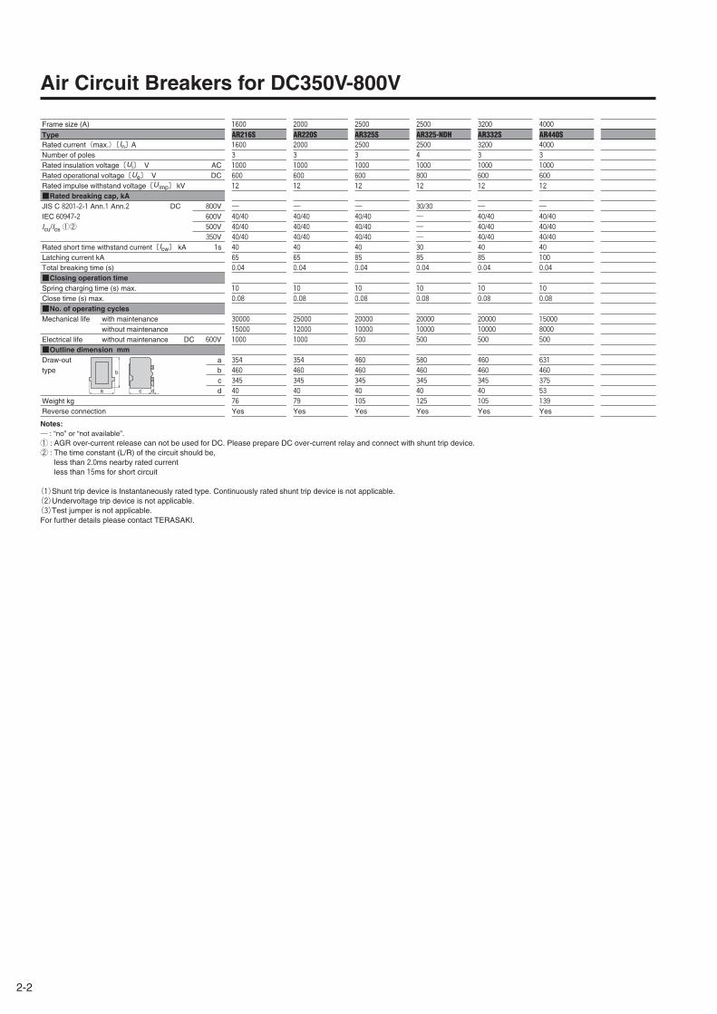
It is more difficult to interrupt DC current than AC current because DC current does not have a zero point. Therefore for high
DC voltages, 3-pole or 4-pole circuit breaker main contacts are connected in series to ensure breaking performance. As
illustrated below, the main power conductors for DC-use air circuit breakers, moulded case circuit breakers, and switch
disconnectors shall be connected generally as shown below but also depending on the type of breaker, the number of poles,
and the DC operating voltage.
Type of breakersNo.s ofpoles
Applicable voltage
(V)
Non-grounded system(Protection + Isolation function)
Applicable voltage
(V)
Ordinallyconnection
Source
Load
Source
Load
Source
Load
Reverseconnection
Load
Source
Source
Load
Source
Load
Applicable voltage
(V)
S1000-ND
✽:2 poles breaker is a 3 pole breaker with the center pole omitted.
2P ≦250 ≦250 ≦150
Grounded system(Protection)
Grounded system(Protection + Isolation function)
Rated breakingcapacityIcu/Ics
Rated breakingcapacityIcu/Ics
Rated breakingcapacityIcu/Ics
50kA/20kA 50kA/20kA 50kA/20kA
Type of breakersNo.s ofpoles
Applicable voltage
(V)
Non-grounded system(Protection + Isolation function)
Applicable voltage
(V)
Ordinallyconnection
Source
Load
Source
Load
Source
Load
Applicable voltage
(V)
XS3200ND
✽:2 poles breaker is a 3 pole breaker with the center pole omitted.
2P ≦250 ≦250 ≦150
Grounded system(Protection)
Grounded system(Protection + Isolation function)
Rated breakingcapacityIcu/Ics
Rated breakingcapacityIcu/Ics
Rated breakingcapacityIcu/Ics
50kA/30kA 50kA/30kA 50kA/30kA
XS1250ND 2P ≦250 50kA/30kA ≦250 50kA/30kA ≦150 50kA/30kA
XS1600ND 2P ≦250 50kA/30kA ≦250 50kA/30kA ≦150 50kA/30kA
XS2000ND 2P ≦250 50kA/30kA ≦250 50kA/30kA ≦150 50kA/30kA
XS2500ND 2P ≦250 50kA/30kA ≦250 50kA/30kA ≦150 50kA/30kA
✽:2 poles breaker is a 3 pole breaker with the center pole omitted.
Type of breakersNo.s ofpoles
Applicable voltage
(V)
Non-grounded system(Protection + Isolation function)
Applicable voltage
(V)
Ordinallyconnection
Source
Load
Source
Load
Source
Load
Reverseconnection
Source
Load
Source
Load
Source
Load
Applicable voltage
(V)
S160-SD 3P ≦600 ≦600 ≦400
S160-SD 3P ≦500 ≦500 ≦350
S160-SD 3P ≦350 ≦350 ≦250
S160-GD 3P ≦600 ≦600 ≦400
S160-GD 3P ≦500 ≦500 ≦350
S250-SD 3P ≦600 ≦600 ≦400
S250-SD 3P ≦500 ≦500 ≦350
S250-SD 3P ≦350 ≦350 ≦250
S250-GD 3P ≦600 ≦600 ≦400
S250-GD 3P ≦500 ≦500 ≦350
S400-ND 3P ≦600 ≦600 ≦400
S400-ND 3P ≦350 ≦350 ≦250
S800-ND 3P ≦600 ≦600 ≦400
S800-ND 3P ≦350 ≦350 ≦250
S1000-ND 3P ≦600 ≦600 ≦400
S1000-ND 3P ≦350 ≦350 ≦250
PVS160-SDL 3P ≦750 ≦750 ≦500
PVS250-SDL 3P ≦750 ≦750 ≦500
PVS400-NDL 3P ≦750 ≦750 ≦500
PVS800-NDL 3P ≦750 ≦750 ≦500
S160-SDN 3P ≦600 ≦600 ≦400
S250-SDN 3P ≦600 ≦600 ≦400
Grounded system(Protection)
Grounded system(Protection + Isolation function)
Rated breakingcapacityIcu/Ics
Rated breakingcapacityIcu/Ics
Rated breakingcapacityIcu/Ics
5kA/5kA 5kA/5kA 5kA/5kA
7.5kA/7.5kA 7.5kA/7.5kA 7.5kA/7.5kA
10kA/10kA 10kA/10kA 10kA/10kA
10kA/5kA 10kA/5kA 10kA/5kA
15kA/7.5kA 15kA/7.5kA 15kA/7.5kA
5kA/5kA 5kA/5kA 5kA/5kA
7.5kA/7.5kA 7.5kA/7.5kA 7.5kA/7.5kA
10kA/10kA 10kA/10kA 10kA/10kA
10kA/5kA 10kA/5kA 10kA/5kA
15kA/7.5kA 15kA/7.5kA 15kA/7.5kA
15kA/15kA 15kA/15kA 15kA/15kA
20kA/20kA 20kA/20kA 20kA/20kA
20kA/10kA 20kA/10kA 20kA/10kA
30kA/15kA 30kA/15kA 30kA/15kA
20kA/10kA 20kA/10kA 20kA/10kA
30kA/15kA 30kA/15kA 30kA/15kA
5kA/5kA 5kA/5kA 5kA/5kA
5kA/5kA 5kA/5kA 5kA/5kA
10kA/5kA 10kA/5kA 10kA/5kA
10kA/10kA 10kA/10kA 10kA/10kA
― ― ―
― ― ―
PVE160-SDL 3P ≦750 3kA/3kA ≦750 3kA/3kA ≦500 3kA/3kA
PVS250-SNL 3P ≦750 ― ≦750 ―
PVS400-NNL 3P ≦750 ― ≦750 ―
PVS800-NNL 3P ≦750 ― ≦750 ―
4-3
4
Mo
un
ting
and
Co
nn
ection

4-4
Connection of conductors to DC circuit breakers
Type of breakersNo.s ofpoles
Applicable voltage
(V)
Non-grounded system(Protection + Isolation function)
Applicable voltage
(V)
Ordinallyconnection
Source
Load
Source
Load
Source
Load
Applicable voltage
(V)
XS3200ND 3P ≦500 ≦500 ≦350
Grounded system(Protection)
Grounded system(Protection + Isolation function)
Rated breakingcapacityIcu/Ics
Rated breakingcapacityIcu/Ics
Rated breakingcapacityIcu/Ics
50kA/25kA 50kA/25kA 50kA/25kA
XS2000ND 3P ≦500 50kA/25kA ≦500 50kA/25kA ≦350 50kA/25kA
XS2500ND 3P ≦600 20kA/15kA ≦600 20kA/15kA ≦400 20kA/15kA
XS2500ND 3P ≦500 50kA/25kA ≦500 50kA/25kA ≦350 50kA/25kA
XS3200ND 3P ≦600 20kA/15kA ≦600 20kA/15kA ≦400 20kA/15kA
XS1250ND 3P ≦600 20kA/15kA ≦600 20kA/15kA ≦400 20kA/15kA
XS1250ND 3P ≦500 50kA/25kA ≦500 50kA/25kA ≦350 50kA/25kA
XS1600ND 3P ≦600 20kA/15kA ≦600 20kA/15kA ≦400 20kA/15kA
XS1600ND 3P ≦500 50kA/25kA ≦500 50kA/25kA ≦350 50kA/25kA
XS2000ND 3P ≦600 20kA/15kA ≦600 20kA/15kA ≦400 20kA/15kA

Type of breakersNo.s ofpoles
Applicable voltage
(V)
Non-grounded system(Protection + Isolation function)
Applicable voltage
(V)
Ordinallyconnection
Source
Load
Source
Load
Source
Load
Applicable voltage
(V)
PVS800-NNH 4P ≦1000 ≦1000
Grounded system(Protection)
Grounded system(Protection + Isolation function)
Rated breakingcapacityIcu/Ics
Rated breakingcapacityIcu/Ics
Rated breakingcapacityIcu/Ics
― ―
PVS250-SNL 4P ≦800 ― ≦800 ― ≦600 ―
PVS400-NNL 4P ≦800 ― ≦800 ― ≦750 ―
PVS400-NNH 4P ≦1000 ― ≦1000 ―
PVS800-NNL 4P ≦800 ― ≦800 ― ≦750 ―
PVS160-SDL 4P ≦750 10kA/5kA ≦750 10kA/5kA ≦550 10kA/5kA
PVS400-NDL 4P ≦750 10kA/10kA ≦750 10kA/10kA ≦750 10kA/10kA ②
PVS400-NDH 4P ≦1000 5kA/5kA ≦1000 5kA/5kA
PVS800-NDL 4P ≦750 10kA/10kA ≦750 10kA/10kA ≦750 10kA/10kA
PVS800-NDH 4P ≦1000 5kA/5kA ≦1000 5kA/5kA ≦750 5kA/5kA
Reverseconnection
Source
Load
Source
Load
Source
Load
PVS250-SDL 4P ≦750 10kA/5kA ≦750 10kA/5kA ≦550 10kA/5kA
PVS160-SDH 4P ≦1000 5kA/5kA ≦1000 5kA/5kA ≦750 5kA/5kA
PVS250-SDH 4P ≦1000 5kA/5kA ≦1000 5kA/5kA ≦750 5kA/5kA
PVS160-SNL 4P ≦800 ― ≦800 ― ≦600 ―
PVS160-SNH 4P ≦1000 ― ≦1000 ― ≦750 ―
PVS250-SNH 4P ≦1000 ― ≦1000 ― ≦750 ―
PVS160-GDH 4P ≦1000 10kA/5kA ≦1000 10kA/5kA ≦750 10kA/5kA
PVS250-GDH 4P ≦1000 10kA/5kA ≦1000 10kA/5kA ≦750 10kA/5kA
4-5
4
Mo
un
ting
and
Co
nn
ection
Note ②:The breaking capacity goes down to Icu10kA / Ics5kA for ground fault protection.

4-6
Connection of conductors to DC circuit breakers
Type of breakersNo.s ofpoles
Applicable voltage
(V)
Non-grounded system(Protection + Isolation function)
Applicable voltage
(V)
Ordinallyconnection
Source
Load
Source
Load
Source
Load
Reverseconnection
Source
Load
Source
Load
Source
Load
Applicable voltage
(V)
Note ③:AGR over-current release can not be used for DC. Please prepare DC over-current relay and connect with shunt trip device.
Grounded system(Protection)
Grounded system(Protection + Isolation function)
Rated breakingcapacityIcu/Ics
Rated breakingcapacityIcu/Ics
Rated breakingcapacityIcu/Ics
AR325-NDH ③ 4P ≦800 30kA/30kA ≦800 30kA/30kA ≦600 30kA/30kA
Type of breakersNo.s ofpoles
Applicable voltage
(V)
Non-grounded system(Protection + Isolation function)
Applicable voltage
(V)
Ordinallyconnection
Source
Load
Source
Load
Source
Load
Reverseconnection
Source
Load
Source
Load
Source
Load
Applicable voltage
(V)
AR216S ③
Note ③:AGR over-current release can not be used for DC. Please prepare DC over-current relay and connect with shunt trip device.
3P ≦600 ≦600 ≦400
Grounded system(Protection)
Grounded system(Protection + Isolation function)
Rated breakingcapacityIcu/Ics
Rated breakingcapacityIcu/Ics
Rated breakingcapacityIcu/Ics
40kA/40kA 40kA/40kA 40kA/40kA
AR220S ③ 3P ≦600 40kA/40kA ≦600 40kA/40kA ≦400 40kA/40kA
AR325S ③ 3P ≦600 40kA/40kA ≦600 40kA/40kA ≦400 40kA/40kA
AR440S ③ 3P ≦600 40kA/40kA ≦600 40kA/40kA ≦400 40kA/40kA
AR332S ③ 3P ≦600 40kA/40kA ≦600 40kA/40kA ≦400 40kA/40kA
4-7
4
Mo
un
ting
and
Co
nn
ection
Insulation distance DC600V or less
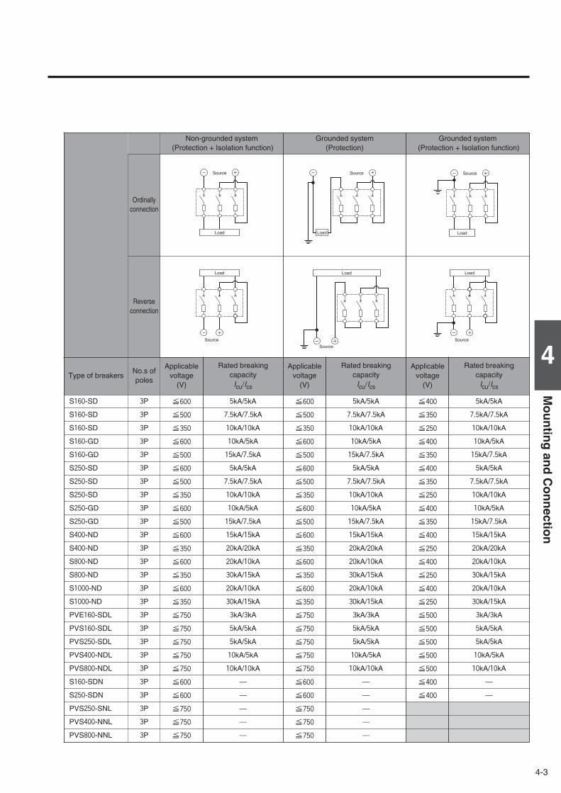
The insulation distances between the breaker and earthed metal parts and insulators shown in the table below must be
maintained to prevent arcing faults occurring due to conductive ionised gas. In addition, any exposed line-side conductors
must be completely covered, right up the breaker casing or to below the height protected by any interpole barriers. This can
done by using an insulation tube or tape, in order to provide positive protection against short circuit or ground fault due to
metal chipping, surge voltage, dust particles or salt. If terminal covers are not being used, the interpole barriers supplied with
the breaker as standard must be used.
A . Distance from lower breaker to exposed live part of upper breaker terminal (front connection) or distance fromlower breaker to end face of upper breaker (rear connection).
B1. Distance from end face of breaker to top plate.B2. Distance from end face of breaker to insulation plate.C . Gap between breakers.D . Distance from side of breaker to side plate (earthed metal).E . Dimension of insulation over exposed conductors.
Front connection, terminal screw
Front connection, extension bar
Rear connection, Plug-in
B1
A
B2
B1
A
B2
B1 E
D
C
A
B2
Insulation plate
Insulation tube or tape
Top plate (earthed metal)
Side plate
Interpole barrier(Insulation tube or tape is also acceptable)
Insulating tube or tape
Interpole barrier
Sheathed wire
Interpole barrier
Line side(ON side)
Load side(OFF side)
Exposedconductor
Compressionterminal
Notes:①. Required to allow free and uninterrupted flow of arc gases. Ensure additional clearance or insulation distance if required to perform wiring, barrier installation or electrical work or to meet
the need for more insulation distance between bare live parts and grounded metal members in a switchboard or the like.②. The figures are for lower breakers.③. When the accessories are fitted it is not possible to set close.④. For front connected breakers, insulate all exposed conductors of the line side until the breaker end. If interpole barriers are packed, be sure to use the barriers; more over, insulate all
exposed conductors by insulating tape or the like so that the tape overlaps with the barriers.⑤. Be sure to install the terminal covers (supplied as standard) on the line side of the breakers.✽. If using extension bars (optional), ensure the insulation distance specified for the application.
Moulded Case Circuit Breakers B1 B2 D E
S400-ND 120 80 〃 80 〃XS1250ND XS2500ND 150 100 〃 100 〃
A Note ②
S800-ND S1000-ND 150XS1600ND XS2000ND 150
Insulation distance, mm (DC 600 V or less) Note ①
S160-SD S160-GD S160-SDN ⑤ 50 50 50 ✽Possible to set close
Note ③25
Not less than the length ofthe bare live part Note④
S250-SD S250-GD S250-SDN ⑤ 65 65 65 ✽ 〃 50 〃
C
XS3200ND

Insulation distance DC750V-1000V
The insulation distances between the breaker and earthed metal parts and insulators shown in the table below must be
maintained to prevent arcing faults occurring due to conductive ionised gas. In addition, any exposed line-side conductors
must be completely covered, right up the breaker casing or to below the height protected by any terminal covers or interpole
barriers. This can done by using an insulation tube or tape, in order to provide positive protection against short circuit or
ground fault due to metal chipping, surge voltage, dust particles or salt. The terminal covers or the interpole barriers supplied
with the breaker as standard must be used. For DC750V-1000V breakers, the front and the rear insulating plates must also
be installed.
B13
0B
A 75 70
70
A
B13
0B
A 75 A
Terminal cover
Terminal cover
Insulating plate
(supplied as standard)
Mounting plate
Insulating plate
(supplied as standard)
Mounting plate
Mounting plate
Terminal cover
Terminal cover
Insulating plate
(supplied as standard)
Mounting plate
PVE160-SDL 3P
Front-connected
Rear-connected
Type Connection
PVE160-SDL 3PFront-connectedRear-connected
25
Minimum insulation distance (mm) Insulating plate
A B Terminal cover
502pcs are supplied for line and load side as standard.
Insulating plate
1pc of 130mm×75mm for F.C.or 140mm×75mm for R.C. is supplied as standard.
4-8

4-9
4
Mo
un
ting
and
Co
nn
ection
5 5
B16
5B
A 105 70
70
A
5 5
B16
5B
A 105 A
Terminal cover
Terminal cover
Insulating plate
(supplied as standard)
Mounting plate
Insulating plate
(supplied as standard)
Mounting plate
Insulating plate
(supplied as standard)
Mounting plate
Terminal cover
Terminal cover
Insulating plate
(supplied as standard)
Mounting plate
Type Connection
PVS160-SDL 3PPVS250-SDL 3PPVS250-SNL 3P
Front-connectedRear-connected
50
Minimum insulation distance (mm) Insulating plate
A B Terminal cover
652pcs are supplied for line and load side as standard.
Insulating plate
2pcs of 115mm×137.5mm are supplied as standard.
PVS160-SDL 3P, PVS250-SDL 3P, PVS250-SNL 3P
Front-connected
Rear-connected

4-10
Insulation distance DC750V-1000V
B16
5B
A 140 68
68
A
B16
5B
A 140 A
Terminal cover
Terminal cover
Mounting plate
Mounting plate
Terminal cover
Terminal cover
Mounting plate
Mounting plate
Type Connection
PVS160-SDL 4PPVS250-SDL 4PPVS160-SNL 4PPVS250-SNL 4P
Front-connectedRear-connected
50
Minimum insulation distance (mm)Terminal cover
A B
65 2pcs are supplied for line and load side as standard.
PVS160-SDL 4P, PVS250-SDL 4P, PVS160-SNL 4P, PVS250-SNL 4P
Front-connected
Rear-connected

4-11
4
Mo
un
ting
and
Co
nn
ection
B16
5B 80
56
A 140 70A
B16
5B 80
56
A 140 70A
Terminal cover
Arc Space (✽)
Arc Space (✽)
Terminal cover
Terminal cover
Terminal cover
Insulating plate
(supplied as standard)
Insulating plate
(supplied as standard)
Mounting plate
Mounting plate
Insulating plate
(Front)
(Not included item)
Insulating plate
(Rear)
Insulating plate
(Front)
(Not included item)
Insulating plate
(Rear)
Mounting plate
Mounting plate
PVS160-GDH 4P, PVS250-GDH 4P
Front-connected
Rear-connected
Type Connection
PVS160-GDH 4PPVS250-GDH 4P
Front-connectedRear-connected
50
Minimum insulation distance (mm) Insulating plate
A B Terminal cover
802pcs are supplied forline and load side asstandard.
Insulating plate
2pcs of 240mm×162.5mm are supplied as standard.
Terminal cover lock
2pcs are supplied forline and load side asstandard.
✽:Arc space is the same dimension as the insulation plate (rear).
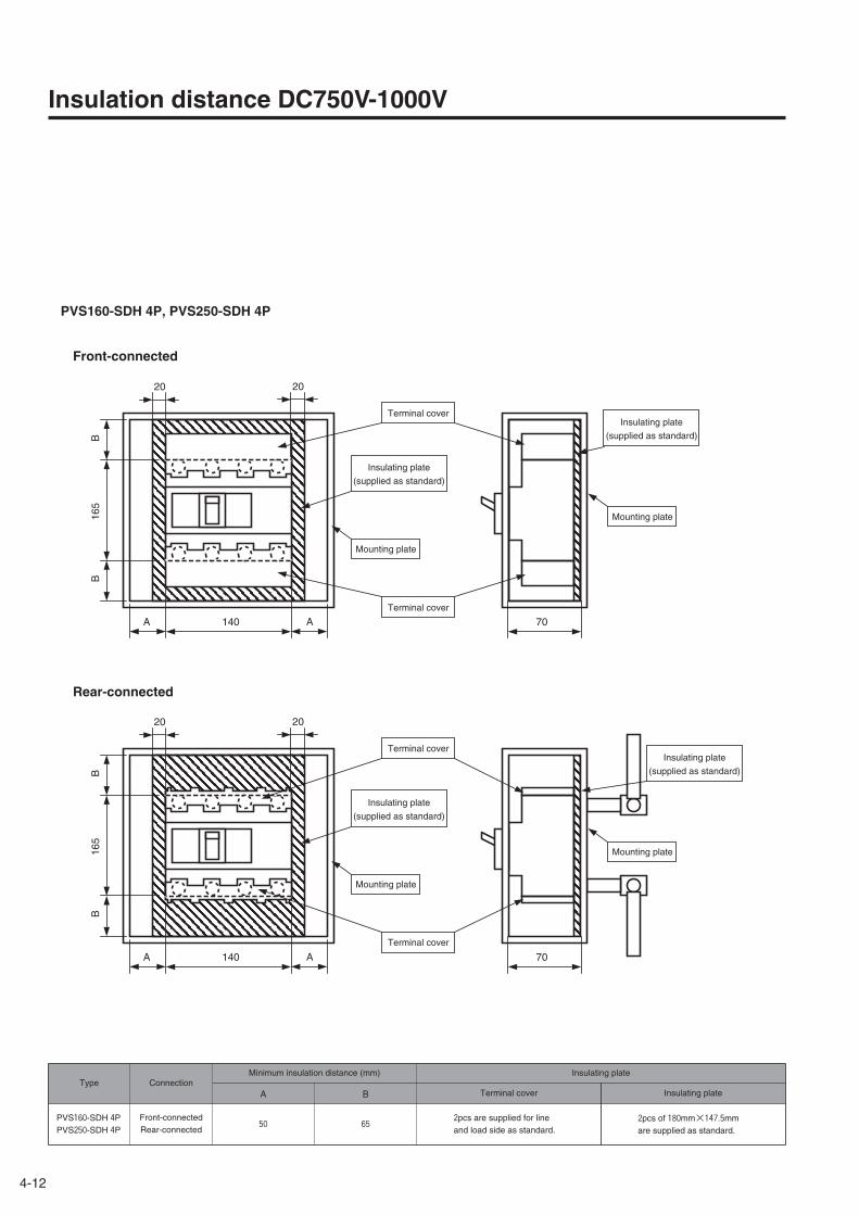
4-12
20 20
B16
5B
A 140 70
70
A
20 20
B16
5B
A 140 A
Terminal cover
Terminal cover
Insulating plate
(supplied as standard)
Mounting plate
Insulating plate
(supplied as standard)
Mounting plate
Insulating plate
(supplied as standard)
Mounting plate
Terminal cover
Terminal cover
Insulating plate
(supplied as standard)
Mounting plate
PVS160-SDH 4P, PVS250-SDH 4P
Front-connected
Rear-connected
Insulation distance DC750V-1000V
Type Connection
PVS160-SDH 4PPVS250-SDH 4P
Front-connectedRear-connected
50
Minimum insulation distance (mm) Insulating plate
A B Terminal cover
652pcs are supplied for line and load side as standard.
Insulating plate
2pcs of 180mm×147.5mm are supplied as standard.

4-13
4
Mo
un
ting
and
Co
nn
ection
13 13
B16
5B
A 140 70
70
A
13 13
B16
5B
A 140 A
Terminal cover
Terminal cover
Insulating plate
(supplied as standard)
Mounting plate
Insulating plate
(supplied as standard)
Mounting plate
Insulating plate
(supplied as standard)
Mounting plate
Terminal cover
Terminal cover
Insulating plate
(supplied as standard)
Mounting plate
PVS160-SNH 4P, PVS250-SNH 4P
Front-connected
Rear-connected
Type Connection
PVS160-SNH 4PPVS250-SNH 4P
Front-connectedRear-connected
30
Minimum insulation distance (mm) Insulating plate
A B Terminal cover
652pcs are supplied for line and load side as standard.
Insulating plate
2pcs of 166mm×137.5mm are supplied as standard.

4-14
Insulation distance DC750V-1000V
PVS400-NDL 3P
Front-connected
Rear-connected
G G
B26
0
C 140 C
105
F
ED
A
420
420
105
E
F
D
C 140 C
AB
260
GG
260
260
Insulating plate
(supplied as standard)
Insulating plate
(supplied as standard)
Mounting plate
Mounting plate
Ionised gas area
Ionised gas area
Interpole barrier
Insulating plate
Interpole barrier
Insulating plate
Type Connection
PVS400-NDL 3PFront-connectedRear-connected
160 Not supplied Supplied as standard
Minimum insulation distance (mm) Insulating plate
A B C D E F Front panel side Mounting plate side
80 80 30 140 160
G
60
4-15
4
Mo
un
ting
and
Co
nn
ection
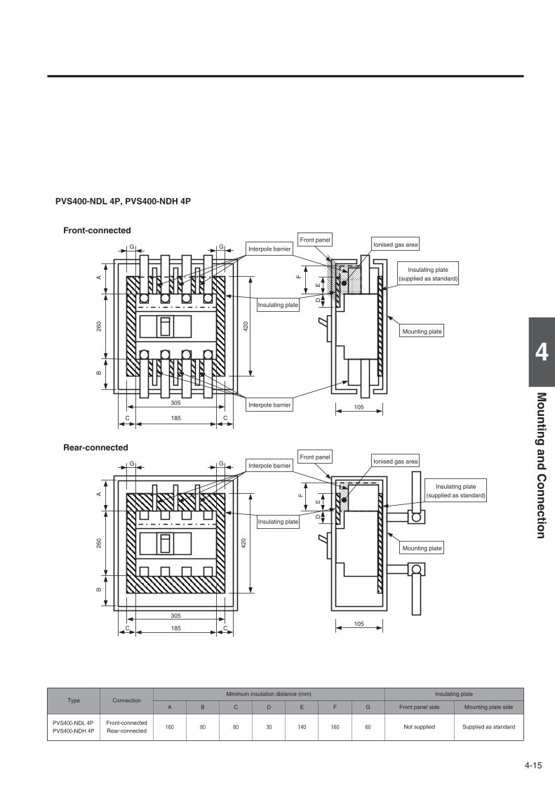
G G
B26
0
C 185 C
105
F
ED
A
420
420
105
E
F
D
C 185 C
AB
260
GG
305
305
Ionised gas area
Ionised gas area
Interpole barrier
Front panel
Front panel
Insulating plate
(supplied as standard)
Insulating plate
(supplied as standard)
Mounting plate
Mounting plate
Interpole barrier
Interpole barrier
Insulating plate
Insulating plate
Type Connection
PVS400-NDL 4PPVS400-NDH 4P
Front-connectedRear-connected
160 Not supplied Supplied as standard
PVS400-NDL 4P, PVS400-NDH 4P
Front-connected
Rear-connected
Minimum insulation distance (mm) Insulating plate
A B C D E F Front panel side Mounting plate side
80 80 30 140 160
G
60

4-16
G G
AB
260
C 140 C 103
F
ED
103
E
F
D
C 140 C
GG
AB
260
Interpole barrier
Interpole barrier
Insulating plate Insulating plate
Front panel Ionised gas area
Ionised gas area
Mounting plate
Interpole barrier
Insulating plateInsulating plate
Front panel
Mounting plate
Interpole barrier
Insulating plateInsulating plate
Front panel
Mounting plate
Insulation distance DC750V-1000V
PVS400-NNL 3P
Front-connected
Rear-connected
Type Connection
PVS400-NNL 3PFront-connectedRear-connected
120 Not supplied Not supplied
Minimum insulation distance (mm) Insulating plate
A B C D E F Front panel side Mounting plate side
80 80 30 80 80
G
40

4-17
4
Mo
un
ting
and
Co
nn
ection
G G
AB
260
C 185 C 103
F
ED
103
E
F
D
C 185 C
GG
AB
260
Interpole barrier
Interpole barrier
Interpole barrier
Insulating plate
Insulating plate
Insulating plate
Insulating plate
Front panel
Front panel
Ionised gas area
Ionised gas area
Mounting plate
Mounting plate
Type Connection
PVS400-NNL 4PPVS400-NNH 4P
Front-connectedRear-connected
120 Not supplied Not supplied
PVS400-NNL 4P, PVS400-NNH 4P
Front-connected
Rear-connected
Minimum insulation distance (mm) Insulating plate
A B C D E F Front panel side Mounting plate side
80 80 30 80 80
G
40

4-18
Insulation distance DC750V-1000V
Front-connected
Rear-connected
513
105
E
F
D
C 210 C
AB
273
330
G G
B27
3
C 210 C
105
F
ED
A
513
330
G G
Insulating plate
(supplied as standard)
Mounting plate
Ionised gas area
Insulating plate
(supplied as standard)
Mounting plate
Ionised gas area
Interpole barrier
Insulating plate
Interpole barrier
Insulating plate
Type Connection
PVS800-NDL 3PFront-connectedRear-connected
160 Not supplied Supplied as standard
PVS800-NDL 3P
Minimum insulation distance (mm) Insulating plate
A B C D E F Front panel side Mounting plate side
80 80 80 140 160
G
60

4-19
4
Mo
un
ting
and
Co
nn
ection
513
105
E
F
D
C 280 C
AB
273
400
G G
B27
3
C 280 C
105
F
ED
A
513
400
G G
Interpole barrier
Interpole barrier
Insulating plate
Insulating plate
Ionised gas areaFront panel
Front panel
Insulating plate
(supplied as standard)
Mounting plate
Ionised gas area
Insulating plate
(supplied as standard)
Mounting plate
Type Connection
PVS800-NDL 4PPVS800-NDH 4P
Front-connectedRear-connected
160 Not supplied Supplied as standard
PVS800-NDL 4P, PVS800-NDH 4P
Front-connected
Rear-connected
Minimum insulation distance (mm) Insulating plate
A B C D E F Front panel side Mounting plate side
80 80 80 140 160
G
60

4-20
取付鉄板
103
E
F
D
C 210 C
AB
273
330
G G
B27
3
C 210 C
103
F
ED
A
330
G G
Interpole barrier
Interpole barrier
Interpole barrier
Insulating plate
Insulating plate
Insulating plate
Front panel
Front panel
Mounting plate
Mounting plate
Insulating plate
(supplied as standard)
Ionised gas area
Ionised gas area
Type Connection
PVS800-NNL 3PFront-connectedRear-connected
120 Not supplied Not supplied
PVS800-NNL 3P
Front-connected
Rear-connected
Minimum insulation distance (mm) Insulating plate
A B C D E F Front panel side Mounting plate side
80 80 80 80 80
G
60
Insulation distance DC750V-1000V

4-21
4
Mo
un
ting
and
Co
nn
ection
103
E
F
D
C 280 C
AB
273
400
G G
B27
3
C 280 C
103
F
ED
A
400
G G
Interpole barrier
Interpole barrier
Insulating plate
Insulating plate
Insulating plate
Ionised gas areaFront panel
Mounting plate
Ionised gas areaFront panel
Mounting plate
Insulating plate
(supplied as standard)
Type Connection
PVS800-NNL 4PPVS800-NNH 4P
Front-connectedRear-connected
120 Not supplied Not supplied
PVS800-NNL 4P, PVS800-NNH 4P
Front-connected
Rear-connected
Minimum insulation distance (mm) Insulating plate
A B C D E F Front panel side Mounting plate side
80 80 80 80 80
G
60


5-1
5
Accesso
ries
5Internally mounted accessories
1. Connection diagrams and terminal numbers…………………………5-22. Possible combinations……………………………………………………5-33. Ratings data of auxiliary and alarm switches…………………………5-44. Shunt trip device (SH) ……………………………………………………5-45. Undervoltage trip device (UV)……………………………………………5-4
Externally mounted accessories1. Motor operators (MC) ……………………………………………………5-62. External operating handles ……………………………………………5-12
(1) Breaker-mounted (field installable small type) (HB) …………5-12(2) Door-mounted (depth adjustable) (HP) …………………………5-20
3. Toggle holder (HH) and toggle lock (HL) ……………………………5-274. Terminal covers …………………………………………………………5-285. Terminal blocks (TF) ……………………………………………………5-32
Accessories

5-2
Internally mounted accessories
1. Connection diagrams and terminal numbers
D1 D2
U1 U2
12/AXb1 14/AXa1
11/AXc1
12/AXb1 14/AXa1
11/AXc1
22/AXb2 24/AXa2
21/AXc2
12/AXb1 14/AXa1
11/AXc1
22/AXb2 24/AXa2
21/AXc2
32/AXb3 34/AXa3
31/AXc3
42/AXb4 44/AXa4
41/AXc4
AXb1 AXa1
AXc1
AXb2 AXa2
AXc2
AXb3 AXa3
AXc3
AXb4 AXa4
AXc4
AXb5 AXa5
AXc5
AXb6 AXa6
AXc6
92/ALb1 94/ALa1
TRIP
91/ALc1
92/ALb1 94/ALa1
TRIP
91/ALc1
02/ALb2 04/ALa2
TRIP
01/ALc2
ALb1 ALa1
TRIP
ALc1
C1 C2
S2 S1~(-)
~(+)
Applicable to MCCB type of “XS”. Shunt trips are fitted with anti-burn switches.
Applicable to TemBreak2 breakers. Shunt trips are continuous rating without anti-burn switches.
Ex. 1pc Aux. Switch installed.
Ex. 2pcs Aux. Switch installed.
Ex. 4pcs Aux. Switch installed.
Ex. 6pcs Aux. Switch installed.This is for MCCB type of “XS”.
Ex. 1pc Alarm switch for MCCB type of “XS”.
Ex. 1pc Alarm switch installed.
Ex. 2pcs Alarm switch installed. *Special application.
Applicable to Tem Breakers2.
Applicable to XS1250ND and XS1600ND.
Accessory Combination symbol Connection diagram and terminal No. Remarks
Shu
nt tr
ip d
evic
e (S
H)
Aux
iliar
y sw
itch
(AX
)A
larm
sw
itch
(AL)
Und
ervo
ltage
tr
ip d
evic
e (U
V)
• Without anti-burn switch
• With anti-burn switch
For DC

5-3
5
Accesso
ries
3 22 33
1000V
PVS160-SNL 4P,PVS250-SNL 4P
PVS400-NNL 4P PVS800-NNL 4P
PVS160-SDL 3P,PVS250-SDL 3P,PVS160-SDL 4P,PVS250-SDL 4P,PVS250-SNL 3P
PVS400-NDH 4P,PVS400-NNH 4P
PVS800-NDH 4P,PVS800-GDH 4P,PVS800-NNH 4P
PVE160-SDL 3P
PVS160-SDH 4P,PVS250-SDH 4P,PVS160-SNH 4P,PVS250-SNH 4P,PVS160-GDH 4P,PVS250-GDH 4P
PVS400-NDL 3P,PVS400-NDL 4P,PVS400-NNL 3P
PVS800-NDL 3P, PVS800-NDL 4P, PVS800-NNL 3P
S160-SD 3P,S160-GD 3P,S160-SDN 3P
S250-SD 3P,S250-GD 3P,S250-SDN 3P
S400-ND 3P S800-ND 3P,S1000-ND 2P,S1000-ND 3P
XS1250ND 2P,XS1600ND 2P,XS1250ND 3P,XS1600ND 3P
XS2000ND 2P,XS2500ND 2P,XS3200ND 2P,XS2000ND 3P,XS2500ND 3P,XS3200ND 3P
800V
750V
250~600V
AX
AL
SH
AL
AX
UV
AL
AX
SH
UV
AX
AL
AX
SH
AX
UV
AL
SH
AL
UV
33 3
Number of poles q
Com
bina
tions
of a
cces
sorie
sT
yp
e
2. Possible combinations
Notes:q : For the four-pole type, see the column for the three-pole type.w : A breaker with AC UVT is provided with an external UVT controller. See page 5-5.

5-4
Internally mounted accessories
Type of breaker
Standard For microload 1AC (V) DC (V)
Minimumload
DC(V)Minimum
loadVoltage
(V)
Current (A)Voltage
(V)
Current (A)Voltage
(V)
Current (A)
Resistiveload
Inductiveload
Resistiveload
Inductiveload
Resistiveload
S160-SD, S160-GD, S160-SDN,S250-SD, S250-GD, S250-SDN,S400-ND, S800-ND, S1000-ND,PVE160-SDL, PVS160-SDL, PVS250-SDL,PVS160-SNL, PVS250-SNL, PVS160-SDH, PVS250-SDH,PVS160-SNH, PVS250-SNH, PVS160-GDH, PVS250-GDH,PVS400-NDL, PVS400-NNL,PVS400-NDH, PVS400-NNH,PVS800-NDL, PVS800-NNL, PVS800-NDH,PVS800-GDH, PVS800-NNH
480 ― ― 250 ― ―
DC15V100mA
30 0.1 DC5V1mA
250 3 2 125 0.4 0.05
125 3 2 30 3 2
XS1250ND, XS1600ND,XS2000ND, XS2500ND, XS3200ND
480 3 2 250 0.3 0.3 DC5V160mADC30V26.7mA
30 0.1DC5V1mADC30V1mA
250 5 5 125 0.6 0.6125 5 5 30 5 4
3. Ratings data of auxiliary and alarm switches
• The applicable load of the switch shall be no larger than the rating and no smaller than the minimum load.
Ratings of AX and AL
Note: 1 This is a custom-made product. When ordering for this product, specify that it is intended for microlead use.Note: 2 The inductive load means power factor of no smaller than 0.4 for AC and time constant of no larger than 7 ms for DC.
Type of breakerPeak exciting current, A
Ratedvoltage
AC (V) DC (V)
100-120 200-240 380-450 24 48 100-120 200-240S160-SD, S160-GD, S160-SDN,S250-SD, S250-GD, S250-SDN,S400-ND, S800-ND, S1000-ND,PVE160-SDL, PVS160-SDL, PVS250-SDL,PVS160-SNL, PVS250-SNL, PVS160-SDH,PVS250-SDH,PVS160-SNH, PVS250-SNH,PVS160-GDH, PVS250-GDHPVS400-NDL, PVS400-NNL,PVS400-NDH, PVS400-NNH,PVS800-NDL, PVS800-NNL, PVS800-NDH, PVS800-GDH, PVS800-NNH
0.014 0.014 0.0065 0.03 0.03 0.011 0.011
4. Shunt trip device (SH)Ratings of SHT
Notes: 3: Exclusive use for 200V class and 400V class.(1) The permissible voltage range is from 70% to 110% of the rated voltage. Ensure that the voltage does not drop exceeding the permissible voltage range when SHT is actuated.(2) Breaker contacts usually start opening within 30 ms after the rated voltage is applied to the breaker.
Type of breakerPeak exciting current, A (AC 60Hz)
Ratedvoltage
AC (V) DC (V)
100-115 200-480 24 48 100-115 200-230
XS2000ND, XS2500ND, XS3200ND1.1
0.4(AC200-240V)0.93(AC380-480V)
3
2.52 1.55 0.67 0.35
XS1250ND, XS1600ND 1.1 0.93 2.52 1.55 0.67 0.35
5. Undervoltage trip device (UV)
Note: 1: No UVT controller is required.(1) Tripping voltage is from 35% to 70% of the rated voltage. Resettable voltage is 85% or less of the rated voltage.
Note: 1: No UVT controller is required.(1) Tripping voltage is from 35% to 70% of the rated voltage. Resettable voltage is 85% or less of the rated voltage.
(1)Ratings of UVT with Inst
Ratedvoltage
AC (V)
100-110 200-220 380-415 24 100-120 200-240
Power supply capacity, VA 1 Exciting current, mA 1DC (V)
S800-ND, S1000-ND,PVS800-NDL, PVS800-NNL, PVS800-NDH,PVS800-GDH, PVS800-NNH
1.5 2.4 2.1 29 13 11
115-120 230-240 440-450
1.6 2.9 2.3
Type of breaker
Type of breakerPower supply capacity, VA 1
Ratedvoltage
AC (V) DC (V)
100-120 200-240 380-450 24 100-120 200-240
S400-ND, PVS400-NDL, PVS400-NNL,PVS400-NDH, PVS400-NNH
1.4 2.8 2.3 23 10 10
Exciting current, mA 1
S160-SD, S160-GD, S160-SDN,S250-SD, S250-GD, S250-SDN,PVE160-SDL, PVS160-SDL, PVS250-SDL,PVS160-SNL, PVS250-SNL, PVS160-SDH, PVS250-SDH,PVS160-SNH, PVS250-SNH, PVS160-GDH, PVS250-GDH
1.4 1.5 2.3 23 10 3.5
Connection diagramand terminal No.
Connection diagramand terminal No.
Connection diagramand terminal No.
D1 D2
D1 D2
Connection diagramand terminal No.
Without anti-burn swi
C2 C1
With anti-burn switch
S2 S1~(-)
~(+)

Type of breaker
Power supply capacity, VA 1
Ratedvoltage
AC (V) DC (V)
100-120 200-240 380-450 24 100-115 200-230
Exciting current, mA 1
XS1250ND, XS1600ND ― ― ― 26 9.2 48
XS2000ND, XS2500ND, XS3200ND ― ― ― ― ― ―
Connection diagramand terminal No.
For DC
5-5
5
Accesso
ries
Notes: 1: No UVT controller is required.(1) Tripping voltage is from 35% to 70% of the rated voltage.
Resettable voltage is 85% or less of the rated voltage.(2) The UVT consists of a tripping mechanism and mechanism of maintain handle at OFF position when without the control voltage.
Please reset the breaker before turning the handle to ON position.
(2)Ratings of UVT with Inst
U1 U2
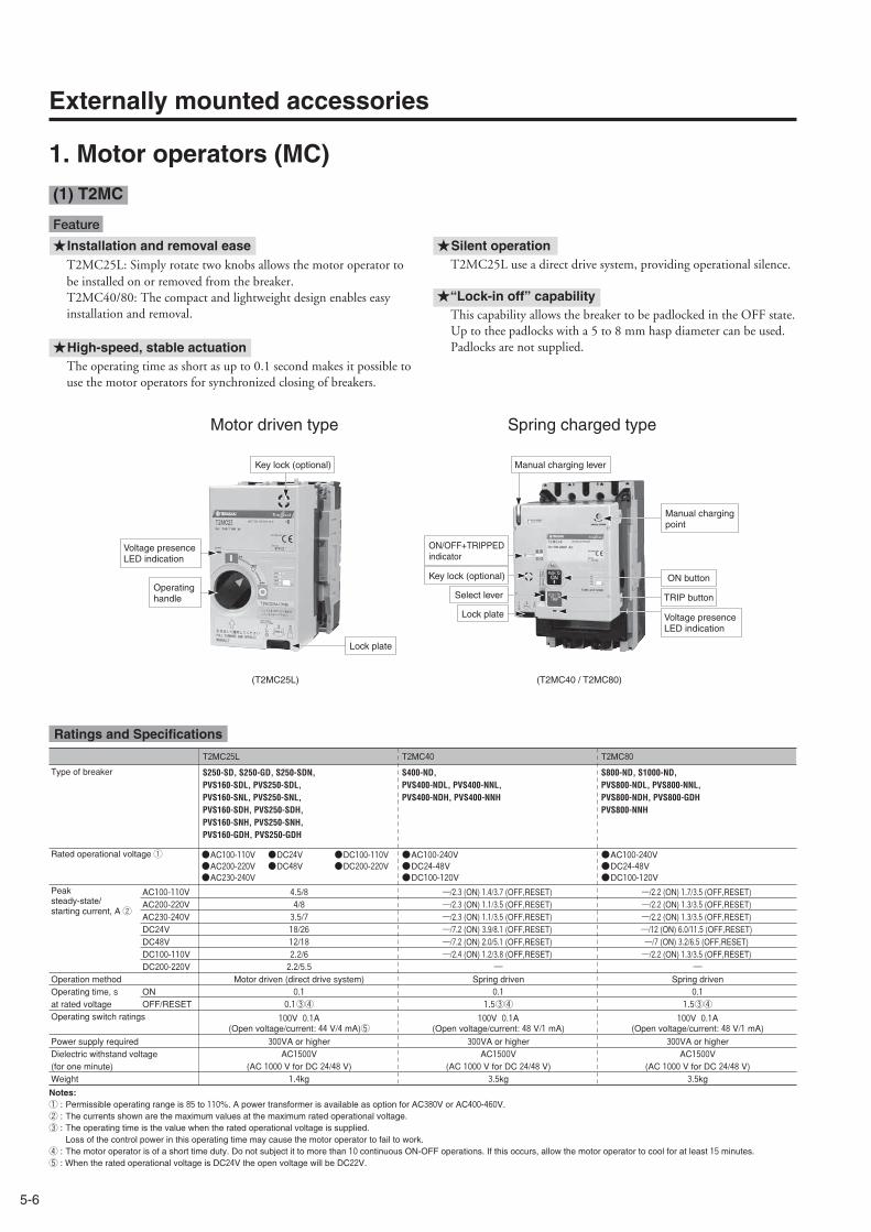
5-6
Externally mounted accessories
Type of breaker
T2MC25L
S250-SD, S250-GD, S250-SDN,PVS160-SDL, PVS250-SDL,PVS160-SNL, PVS250-SNL,PVS160-SDH, PVS250-SDH,PVS160-SNH, PVS250-SNH,PVS160-GDH, PVS250-GDH
T2MC40
S400-ND,PVS400-NDL, PVS400-NNL,PVS400-NDH, PVS400-NNH
●AC100-110V●AC200-220V●AC230-240V
●DC24V●DC48V
●DC100-110V●DC200-220V
●AC100-240V●DC24-48V●DC100-120V
Peak steady-state/starting current, A 2
AC100-110V 4.5/8 ―/2.3 (ON) 1.4/3.7 (OFF,RESET)AC200-220V 4/8 ―/2.3 (ON) 1.1/3.5 (OFF,RESET)AC230-240V 3.5/7 ―/2.3 (ON) 1.1/3.5 (OFF,RESET)DC24V 18/26 ―/7.2 (ON) 3.9/8.1 (OFF,RESET)DC48V 12/18 ―/7.2 (ON) 2.0/5.1 (OFF,RESET)DC100-110V 2.2/6 ―/2.4 (ON) 1.2/3.8 (OFF,RESET)DC200-220V 2.2/5.5 ―
Operation method Motor driven (direct drive system) Spring drivenOperating time, s at rated voltage
ON 0.1 0.1OFF/RESET 0.1③④ 1.5③④
Operating switch ratings 100V 0.1A(Open voltage/current: 44 V/4 mA)⑤
100V 0.1A(Open voltage/current: 48 V/1 mA)
Power supply required 300VA or higher 300VA or higherDielectric withstand voltage (for one minute)
AC1500V(AC 1000 V for DC 24/48 V)
AC1500V(AC 1000 V for DC 24/48 V)
Weight 1.4kg 3.5kg
Rated operational voltage 1
T2MC80
S800-ND, S1000-ND,PVS800-NDL, PVS800-NNL,PVS800-NDH, PVS800-GDHPVS800-NNH
●AC100-240V●DC24-48V●DC100-120V
―/2.2 (ON) 1.7/3.5 (OFF,RESET)―/2.2 (ON) 1.3/3.5 (OFF,RESET)―/2.2 (ON) 1.3/3.5 (OFF,RESET)―/12 (ON) 6.0/11.5 (OFF,RESET)―/7 (ON) 3.2/6.5 (OFF,RESET)―/2.2 (ON) 1.3/3.5 (OFF,RESET)
―Spring driven
0.11.5③④
100V 0.1A(Open voltage/current: 48 V/1 mA)
300VA or higherAC1500V
(AC 1000 V for DC 24/48 V)3.5kg
1. Motor operators (MC)
Ratings and Specifications
Feature
Notes:① : Permissible operating range is 85 to 110%. A power transformer is available as option for AC380V or AC400-460V.② : The currents shown are the maximum values at the maximum rated operational voltage.③ : The operating time is the value when the rated operational voltage is supplied.
Loss of the control power in this operating time may cause the motor operator to fail to work.④ : The motor operator is of a short time duty. Do not subject it to more than 10 continuous ON-OFF operations. If this occurs, allow the motor operator to cool for at least 15 minutes.⑤ : When the rated operational voltage is DC24V the open voltage will be DC22V.
(T2MC25L) (T2MC40 / T2MC80)
Operating handle
Lock plate
Key lock (optional)
Voltage presenceLED indication
Lock plate
Select lever
Manual charging lever
Manual charging point
ON/OFF+TRIPPED indicator
Voltage presenceLED indication
Key lock (optional)
TRIP button
ON button
★Installation and removal easeT2MC25L: Simply rotate two knobs allows the motor operator tobe installed on or removed from the breaker.T2MC40/80: The compact and lightweight design enables easyinstallation and removal.
★High-speed, stable actuationThe operating time as short as up to 0.1 second makes it possible touse the motor operators for synchronized closing of breakers.
★Silent operationT2MC25L use a direct drive system, providing operational silence.
★“Lock-in off” capabilityThis capability allows the breaker to be padlocked in the OFF state.Up to thee padlocks with a 5 to 8 mm hasp diameter can be used.Padlocks are not supplied.
Motor driven type Spring charged type
(1) T2MC
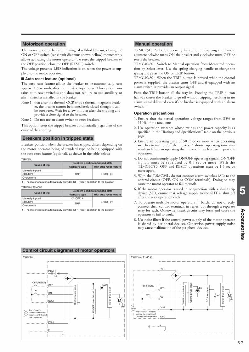
5-7
5
Accesso
ries
LEDOFF
DS
OFF(RESET)
+
–
M
P1(+)
ON
COM
P2(–)
E
ON
Uc
The “+” and “–” symbols indicate the polarities of DC-rated motor operators.
Con
trol
pow
er c
ircui
t
ON
/OF
F c
ontr
ol c
ircui
t
Mot
or d
rive
circ
uit LED
LRC
P1(+)
P2(–)
OFF
ON
COM
E
OFF(RESET)
ON M
Uc
+
– The “+” and “–” symbols indicate the polarities of DC-rated motor operators.
Con
trol
pow
er c
ircui
t
ON
/OFF
con
trol c
ircui
t
Mot
or d
rive
circ
uit
LRC
driv
e ci
rcui
t
T2MC25L T2MC40 / T2MC80
Motorized operationThe motor operator has an input-signal self-hold circuit; closing theON or OFF switch (see circuit diagrams shown bellow) momentarilyallows activating the motor operator. To reset the tripped breaker tothe OFF position, close the OFF (RESET) switch.The voltage presence LED indication is on when the power is sup-plied to the motor operator.
■ Auto reset feature (optional)The auto reset feature allows the breaker to be automatically resetapprox. 1.5 seconds after the breaker trips open. This option con-tains auto-reset switches and does not require to use auxiliary oralarm switches installed in the breaker.Note 1: that after the thermal OCR trips a thermal-magnetic break-
er, the breaker cannot be immediately closed though it canbe auto-reset. Wait for a few minutes after the tripping andprovide a close signal to the breaker.
Note 2: Do not use an alarm switch to reset breakers.
This option resets the tripped breaker automatically, regardless of thecause of the tripping.
Manual operationT2MC25L: Pull the operating handle out. Rotating the handlecounterclockwise turns ON the breaker and clockwise turns OFF orresets the breaker.T2MC40/80 : Switch to Manual operation from Motorized opera-tion by Select lever. Use the spring charging handle to charge thespring and press the ON or TRIP button.T2MC40/80 : When the TRIP button is pressed while the controlpower is supplied, the breaker turns OFF and if equipped with analarm switch, it provides an output signal.
Press the TRIP button all the way in. Pressing the TRIP buttonhalfway causes the breaker to go off without tripping, resulting in noalarm signal delivered even if the breaker is equipped with an alarmswitch.
Control circuit diagrams of motor operators
Operation precautions1. Ensure that the actual operation voltage ranges from 85% to
110% of the rated one.2. Use operation switches whose ratings and power capacity is as
specified in the “Ratings and Specifications” table on the previouspage.
3. Ensure an operating time of 50 msec or more when operatingswitches to turn on/off the breaker. A shorter operating time mayresult in failure in operating the breaker. In such a case, repeat theoperation.
4. Do not continuously apply ON/OFF operating signals. ON/OFFsignals must be separated by 0.3 sec or more. With theT2MC40/80, OFF and RESET operations must be 1.5 sec ormore apart.
5. With the T2MC25L, do not connect alarm switches (AL) to thecontrol circuit (OFF, ON or COM terminals). Doing so maycause the motor operator to fail to work.
6. If the motor operator is used in conjunction with a shunt tripdevice (SH), ensure that voltage supply to the SHT is shut offafter the reset operation ends.
7. To operate multiple motor operators in batch, do not directlyconnect their control terminals in series, but through a separaterelay for each. Otherwise, sneak circuits may form and cause theoperators to fail to work.
8. Use noise filters if the control power supply of the motor operatoris shared by peripheral devices. Otherwise, power supply noisemay cause malfunction of the peripheral devices.
Breakers position in tripped stateBreakers position when the breaker has tripped differs depending onthe motor operator being of standard type or being equipped withthe auto reset feature (optional), as shown in the table below:
Cause of tripBreakers position in tripped state
Manually tripped
TRIP ○ (OFF)*SHT/UVT
Standard type With auto reset feature
Overcurrent
*: The motor operator automatically provides OFF (reset) operation to the breaker.
T2MC25L
Cause of tripBreakers position in tripped state
Manually tripped ○ (OFF)*○ (OFF)*SHT/UVT
TRIP
Standard type With auto reset feature
Overcurrent
*: The motor operator automatically provides OFF (reset) operation to the breaker.
T2MC40 / T2MC80

5-8
Externally mounted accessories
Manual operating handle
Lock plate
Indicator
Applicable breakers
T1MCX6XS1250ND, XS1600ND
●AC100-115V●AC200-230V●DC100-110V●DC24V
Peak steady-state/starting current, A2
AC100-115V ―/3.1
1.8/6.0
AC200-230V ―/1.2
1.0/3.2
DC100-110V ―/0.8
1.1/4.2
DC24V ―/4.5
Operation method Spring charged
Operating time, s@ rated voltage
ON (Max) 0.06
OFF/RESET 3 3
Power supply required 300VA
Dielectric withstand voltage (for one minute) AC1500V4
Weight 6.4kg
Rated operational voltage 1
ON
OFF, RESET
ON
OFF, RESET
ON
OFF, RESET
ON
OFF, RESET 4.0/12.0
1. Motor operators (MC)
Ratings and Specifications Features
Notes:1 : Permissible operating range is 85 to 110%. A power transformer is available as option for AC380V
or AC400-460V.2 : The currents shown are the maximum values at the maximum rated operational voltage.3 : The operating time is the value when the rated operational voltage is supplied.
Loss of the control power in this operating time may cause the motor operator to fail to work.4 : Dielectric withstand voltage for DC 24 V motor is AC 500 V.
★Clear status indication
Color indication: Red means ON, green OFF and whiteTRIPPED.
★Quick closing
Energy in a charged spring closes the breaker 60 msec orless.High-speed, time-stable operation is ensured after multi-ple times of closing cycles.
★Equipped with anti-pumping circuit
When the closing signal is applied, TRIP-RESET-ONcycles are not repeated even though the cause of trippingis in the breaker.
★Ease of manual ON-OFF operation
Simply pressing the ON or OFF button closes or opensthe breaker.
★“Lock-in off” capability
This capability allows the breaker to bepadlocked in the OFF state.Padlocks are not supplied.
φ5.5
(2) T1MC
(T1MCX6)Spring charged type

5-9
5
Accesso
ries
LRC YM
“OFF”atspringcharged
“OFF”atlocked
EMP2MP1
SOURCE
OnONSwitch
E- E-
OFFSwitch
Off
“ON”atspringcharged
“ON”atspringcharged
“OFF”atspring
charged
“OFF”atMCCB:ONorTRIPPosition
“ON”atMCCB:ONorTRIPPosition
Yc
YcYaYaXb
Xb Xa
X
LS HS
LS
(RESET)
X: Anti-pumping relayY: Motor drive relay
LRC: Latch release coil (closing coil)M: Motor
HS: Handle switch: Field coil: Resistor
+ –
AUTO RESETSWITCH(OPTION)
Control circuit diagram
Operation mechanism
Motorized operation■Breaker ONClosing the ON switch activates the latch release coil (LRC), thereby releasing the closing spring to turn the breaker ON.
■Breaker OFF (RESET)Closing the OFF/RESET switch activates the (Y) control relay, thereby starting the motor to turn the breaker OFF. At the same time, the closingspring is charged. The motor is deenergized when the breaker turns OFF (RESET).
■Breaker auto-reset (optional)The auto-reset option uses an auto-reset switch (alarm switch) through which the closing spring is charged and the breaker is reset automaticallyafter the breaker trips open. This option both for XMD and T2MC will be factory wired. Notes: 1. Installable alarm switch will be only 1 piece.
2. When the breaker is equipped with the auto-reset option, a signal self-hold circuit is required because the signal provided by the alarm switch is a pulse.
Manual operation *■Breaker ON . OFF (RESET)Pulling down the operating lever turns the breaker ON and OFF/RESTalternately. The handle returns to the original position when released.
※With auto-charge/discharge feature:When manual ON operation is performed while the control power isapplied, the handle switch (HS) operates to discharge the closing spring.OFF operation causes the closing spring to be charged. When manual ON or OFF operation is performed while the control poweris lost, and afterwards the control power is recovered, the closing spring isdischarged or charged in the same manner as described above. When the auto-charge/discharge action is in progress, mechanical noiseswill be heard. The noises however do not mean a failure.
Operation Precautions
• Ensure that the actual operation voltage ranges from 85% to 110% of the rated one.
• The currents shown are the maximum values at the maximum rated operational voltage.
• When conducting the dielectric withstand voltage test, apply voltage between the control terminal group and ground. Ensure that the testvoltage does not exceed AC 1500 V (AC 500 V if the rated operation voltage is DC 24 V).
• If the breaker is equipped with the UVT device, ensure that the UVT device is reset before providing a closing signal to the breaker.
• It takes up to three seconds to complete motorized OFF operation. If the breaker requires to be immediately opened from a remote location inan emergency, add the SHT or UVT device to the breaker for remote electrical tripping.
• When a thermal-magnetic breaker is tripped by the thermal OCR, wait for a few minutes; then reset the breaker.
• Make sure that the current and switching capacities of the operation switch are appropriate for the application.
• Avoid repeated and continuous applications of the operation power supply to the motor operator.
• Use noise filters if the control power supply of the motor operator is shared by peripheral devices. Otherwise, power supply noise may causemalfunction of the peripheral devices.
• Be sure to apply power to control power terminal MP1. If the breaker is turned ON or OFF manually without power applied to MP1, the autocharge/discharge feature is disabled, and thus the motor operator will not be activated next time. In such a case, applying the rated operationvoltage between control power terminals MP1 and MP2 will enable the auto charge/discharge feature.

5-10
Externally mounted accessories
Series/type of breaker
XMB10
XS2000ND,XS2500ND
●AC100-110V●AC200-220V●DC100-110V
Peak steady-state/starting current, A ③
AC100-110V 0.85/3.5
AC200-220V 1.3/2.1
DC100V 1.1/2.5
DC110V 1.2/3.0Operation method Motor drivenOperating time, s at rated voltage
2.0
1.6④⑤Operating switch ratings 250V, 5APower supply required 300VA or higher
Dielectric withstand voltage (for one minute) AC1000V
Weight 16kg
Rated operational voltage ①
Auto resetOptional ②
Non
XMB12
XS3200ND
●AC100-110V●AC200-220V●DC100-110V
Optional ②
Non
0.85/3.5
1.3/2.1
1.1/2.5
1.2/3.0
Motor driven
2.0
1.6④⑤
250V, 5A300VA or higher
AC1000V
16kg
1. Motor operators (MC)
Motor driven type
Ratings and Specifications
Notes: ①Permissible operating range is 85 to 110%. A power transformer is available as optionfor AC380V or AC400-460V.
②Auto reset require to use auxiliary switch(1b) installed in the breaker. If the numberof auxiliary switches is insufficient, actuatean external relay via an auxiliary switch (1a)and use the relay contact (1b) for autoreset.
③The currents shown are the maximumvalues at the maximum rated operationalvoltage.
④The operating time assume the motoroperator is supplied with the ratedoperation voltage. Loss of the motoroperator to fail to work.
⑤The motor operator is short-time rated. Thenumber of continuous switching (ON-OFF)cycles must not exceed 10. After any 10continuous switching cycles, provide apause of at least 15 minutes to the motoroperator for cooling.
(3) XMB
ON-OFF indicator
Operating handle mounting shaft
ON
OFF/RESET

5-11
5
Accesso
ries
SOURCE
OFF
RESET
AUTO RESET SW (OPTION)
HANDLE SW
MOTOR SW
Xa
Xa
Xb Yb
Xa
Ya
Ya
Ya
X
M
Y
ON
A
1 3
2
4 6
5
7 9
8
B C D E
~ ~ SOURCE
OFF
RESET
AUTO RESET SW (OPTION)
HANDLE SW
MOTOR SW
Xa
Xa
Xb Yb
Xa
Ya
Ya
Ya
X
M
Y
ON
A
1 3
2
4 6
5
7 9
8
B C D E
+ -
• For AC • For DC
Control circuit diagrams of motor operators
Operation mechanism
Motorized operation■Breaker ONClosing the ON switch throws the motor switch from contact status “1-2” to “3-2”, thereby activating the X relay and energizing the motor opera-tor to turn the breaker ON. When the breaker turns ON, the motor switch is thrown from contact status “3-2” to “1-2”, thereby releasing the Xrelay to de-energize and stop the motor operator.
■Breaker OFFClosing the OFF/RESET switch throws the motor switch from contact status “3-2” to “1-2”, thereby activating the Y relay and energizing themotor operator to turn the breaker OFF. When the breaker turns OFF, the motor switch is thrown from contact status “1-2” to “3-2”, therebyreleasing the Y relay to de-energize and stop the motor operator.
■Breaker RESETTo reset the tripped breaker to the OFF position, close the OFF/RESET switch.
■Breaker auto-reset (optional)Using the AUTO RESET auxiliary switch (1b) of the breaker allows resetting the breaker automatically when the breaker trips open. Note: Do not use a normally closed switch as the ON switch. Doing so will result in “ON-TRIP-RESET-ON” cycles repeated unless the cause of tripping is removed.
Manual operationMount the operating handle onto the mounting shaft located on the front of the motor operator and rotate the shaft to turn the breaker ON orOFF. Rotating the handle anti-clockwise turns ON the breaker and clockwise turns OFF or resets the breaker. When the operating handle ismounted, the motorized operation mechanism is disengaged. Removing the handle engages the motorized operation mechanism to enable motor-ized operation.
■Handle switchWith the addition of a handle switch, the motor operator mechanism can be automatically brought to the manually operated position (ON orOFF) on removal of the handle, providing that the motor operator is powered up.
Operation precautions¡When the breaker is ON and is then tripped, the ON/OFF indicator on the motor operator will indicate ON until the breaker is reset.
Note: The breaker's condition may differ.¡Use noise filters if the control power supply of the motor operator is shared by peripheral devices. Otherwise, power supply noise may cause
malfunction of the peripheral devices.

5-12
Externally mounted accessories
The external operating handle is a tool that allows the breaker installed in a switchboard to be operated from outside and complies with IEC 60204-1(IEC 60204-1). The breaker-mounted type external operating handle is designed to be mounted directly to the breaker body.
2. External operating handles
(1) Breaker-mounted (field installable small type) (HB)
Knob
Knob
Slide lever
Breaker toggle
Breaker
Breaker
Handle frame
Handle escutcheon
Handle escutcheon
Gap
(Incorrect)
OFF(O)
ON(I)
OFF(O)
ON(I)
OFF(O)
ON(I)
OFF(O)
ON(I)
OFF(O)
ON(I)
OFF(O)
ON(I)
U: Upper power supply type (standard)
L: Left power supply type
R : Right power supply type
Power supply
Load
Pow
er s
uppl
y
Pow
er s
uppl
y
Load
Load
The ON and OFF positions of the handle and the positions of drilled holes in the panel do not need to be changed depending on the breakermounting direction. The upper power supply type is standard. If a non-standard type is required, state the type when ordering.
• For a change in mounting direction, see the Operating Instructions packaged with the product.
■ Outer view
■ Mounting instructionsThe external operating handle has not been mounted on the breakers. For details on how to mount the handle, see the Operating Instructions packaged with the product.
[1] Mounting of external operating handle assembly• Make sure that the breaker is in the OFF position.• Put the external operating handle assembly onto the breaker in
place so that the breaker handle is engaged with the handlecatch of the assembly. Rotate two knobs to secure the handle assembly.
[2] Installation of handle escutcheon and latch plate• Drill holes in the panel according to the panel cutout
dimensions.Sandwich the panel between the handle escutcheon andlatch plate and temporarily tighten using the suppliedscrews.
• Close the panel. Make adjustment so that the gap between the handleassembly and handle escutcheon is even and the assemblyis not inclined against the breaker.
■ Breaker mounting direction
Dustproof packing (optional)
TypesT2HB16LT2HB25L
(1) Breaker-mounted (field installable small type) (HB)

5-13
5
Accesso
ries
※ : Padlocking in OFF position only required by IEC 60204-1 isalso available.
Order code T2HB16L U R 3 B T
✽: standard specification
T2HB16L T2HB25L
U: Upper power supply type ✽R: Right power supply typeL: Left power supply type
R : RESET open ✽F : OFF open
3 : IP30 ✽5 : IP50S : IP55 (special spec.)
B : Black handle (Light gray base) ✽R : Red handle (Yellow base)
T : Lock in ON or OFF✽ N : Lock in OFF
Type of external operating handle Breaker mounting direction Panel lock Protection degree Colour Padlock
Handle
Panel lock release
Hook lever
Padlock
■ Panel lock mechanism
The external operating handle keeps the panel door locked when inthe ‘ON’ position. There are two types, RESET Open and OFFOpen.
(1) Reset Open (Standard type)The handle is turned to the RESET OPEN position to open thepanel door.
(2) OFF OpenThe handle is turned to the OFF position to open the panel door.
¡Panel lock release knobThe release knob enables the panel door to be opened with thehandle in the ‘ON’ position. To release: turn the release knob inthe direction of anti-clockwise with a flat-bladed screwdriver.
¡Safety interlock (Standard)The safety interlock prevents the breaker from turning ON as longas the panel is open. This interlock can be released using the hooklever.
■ Toggle lock mechanism
¡Padlock (Standard)This mechanism allows the breaker to be padlocked in the ON orOFF position.Padlocks are not supplied. Up to three padlocks can be installed.
ADia.
Type of handle A Dia.
T2HB 13 min ø5.5-8
Padlock dimensions (mm)
■ Protection degree IEC 60529
IP30 standard specification
IP50 optional, with a dust proof packing
IP55 special specification
■ To be stated when ordering

5-14
Externally mounted accessories
109±241.5
75
75
8522
22
200
65 87.5
200
6.5
2020
ON
CL CL
4-φ10
φ65
LH
60
60
CL
LH
1.2-3.2
• Positions of the hinge and handle as seen from the load side of the breaker.Ensure that the hinge is positioned in the area.
Handle escutcheon
Hook lever
PanelPlate thickness
Panel lock release
¡Panel cutout dimensions¡Outline dimensions
Applicable breaker types
S160-SD, S160-GD, S160-SDN,PVE160-SDL
2. External operating handles
T2HB16L HL : Handle Frame Centre LineCL : Handle Centre Line

5-15
5
Accesso
ries
75
109±241.5
2222 8
5
200
65 87.5
200
6.5
2020
75
LH
4-φ10
φ6560
60
CL
LH
CL CL
ON
1.2-3.2
• Positions of the hinge and handle as seen from the load side of the breaker.Ensure that the hinge is positioned in the area.
Handle escutcheon
Hook lever
PanelPlate thickness
Panel lock release
¡Panel cutout dimensions¡Outline dimensions
Applicable breaker types
S250-SD, S250-GD, S250-SDN,PVS160-SDL, PVS250-SDL,PVS160-SNL, PVS250-SNL,PVS160-SDH, PVS250-SDH,PVS160-SNH, PVS250-SNH,PVS160-GDH, PVS250-GDH
T2HB25L HL : Handle Frame Centre LineCL : Handle Centre Line

5-16
Externally mounted accessories
2. External operating handles
Mounting screw
Mounting screw
(2) Breaker-mounted (field installable small type) (HB)
The external operating handle is a tool that allows the breaker installed in a switchboard to be operated from outside and complies with IEC 60204-1. The breaker-mounted type external operating handle is designed to be mounted directly to the breaker body.
TypesT2HB40T2HB80
■ Outer view
Breaker
Breaker
Handle frame
Handle escutcheon
Handle escutcheon
Gap
(Incorrect)
The ON and OFF positions of the handle and the positions of drilled holes in the panel do not need to be changed depending on the breakermounting direction. The upper power supply type is standard. If a non-standard type is required, state the type when ordering.
• For a change in mounting direction, see the Operating Instructions packaged with the product.
U: Upper power supply type (standard)
L: Left power supply type
R : Right power supply type
Power supply
Load
Pow
er s
uppl
y
Pow
er s
uppl
y
Load
Load
■ Mounting instructionsThe external operating handle has not been mounted on the breakers. For details on how to mount the handle, see the Operating Instructions packaged with the product.
[1] Mounting of external operating handle assembly• Make sure that the breaker is in the OFF position.• Put the external operating handle assembly onto the breaker in
place so that the breaker handle is engaged with the handlecatch of the assembly. Rotate two knobs to secure the handle assembly.
• For T2HB40 and T2HB80, tighten the bolts to secure thehandle assembly.
Slide lever
Breaker toggle
[2] Installation of handle escutcheon and latch plate• Drill holes in the panel according to the panel cutout
dimensions.Sandwich the panel between the handle escutcheon andlatch plate and temporarily tighten using the suppliedscrews.
• Close the panel. Make adjustment so that the gap between the handleassembly and handle escutcheon is even and the assemblyis not inclined against the breaker.
Dustproof packing (optional)
■ Breaker mounting direction

5-17
5
Accesso
ries
Handle
Panel lock release
Hook lever
Key lock
IP30 standard specification
IP50 optional, with a dust proof packing
IP55 special specification
Type of handle A Dia.
T2HB 13 min ø5.5-8
Padlock dimensions (mm)
※ : Padlocking in OFF position only required by IEC 60204-1 isalso available.Please specify when ordering.
Order code T2HB40 U R 3 B T
✽: standard specification
T2HB40 T2HB80
U: Upper power supply type ✽R: Right power supply typeL: Left power supply type
R : RESET open ✽F : OFF open
3 : IP30 ✽5 : IP50S : IP55 (special spec.)
B : Black handle (Light gray base) ✽
R : Red handle (Yellow base)
T : with padlock (Lock in ON or OFF) ✽W : with key lock and padlock (Lock in ON or OFF)N : with padlock (lock in OFF)K : with key lock and padlock (lock in OFF)
Type of external operating handle Breaker mounting direction Panel lock Protection degree Colour Key lock / Padlock
■ Panel lock mechanism
The external operating handle keeps the panel door locked when inthe ‘ON’ position. There are two types, RESET Open and OFFOpen.
(1) Reset Open (Standard type)The handle is turned to the RESET OPEN position to open thepanel door.
(2) OFF OpenThe handle is turned to the OFF position to open the panel door.
¡Panel lock release knob (Standard)The release knob enables the panel door to be opened with thehandle in the ‘ON’ position. To release: turn the release knob inthe direction of anti-clockwise with a flat-bladed screwdriver.
¡Safety interlock (Standard)The safety interlock prevents the breaker from turning ON as longas the panel is open. This interlock can be released using the hooklever.
■ Toggle lock mechanism
¡Padlock (Standard)This mechanism allows the breaker to be padlocked in the ON orOFF position.Padlocks are not supplied. Up to three padlocks can be installed.
¡Key lock (Optional)Key locking is possible in the ON or OFF position.
ADia.
■ Protection degree IEC 60529
■ To be stated when ordering

5-18
Externally mounted accessories
Applicable breaker types A(㎜)S400-ND,PVS400-NDL, PVS400-NNL,PVS400-NDH, PVS400-NNH
150±2
B(㎜)
97
2. External operating handles
L
H
C L
L
C
4-φ10
1.2-3.2
22
140
105
90
18
200
9
5
200
12
M6
φ110
10524 A
B
50
15
5130
130 CL
HL
TRIP
ON
OFF
OPEN
RESET
Handle escutcheon
Hook lever
Breaker
Key for key lock(optional)
Panel lock release
Panel
¡Panel cutout dimensions¡Outline dimensions
• Positions of the hinge and handle as seen from the load side of the breaker.Ensure that the hinge is positioned in the area.
T2HB40
■ Outline dimensions ASL : Arrangement Standard Line HL : Handle Frame Centre Line
CL : Handle Centre Line

5-19
5
Accesso
ries
Applicable breaker types
S800-ND, S1000-ND,PVS800-NDL, PVS800-NNL, PVS800-NDHPVS800-GDH, PVS800-NNH
A(㎜)
150±2
1.2-3.2
130
18 12922 5
5130 10 24 50 A 105
105CL CL CL
HL
HL
HL 4-φ10
φ110
200 200
14090
• Positions of the hinge and handle as seen from the load side of the breaker.Ensure that the hinge is positioned in the area.
Handle escutcheon
Hook lever
Panel lock release
¡Panel cutout dimensions¡Outline dimensions
T2HB80
ASL : Arrangement Standard Line HL : Handle Frame Centre Line
CL : Handle Centre Line

5-20
Externally mounted accessories
2. External operating handles
Door-mounted type external operating handles allow breakers installed in control centers or switchboards to be manually operated from outsideand complies with IEC 60204-1. This handle assembly consists of an operation mechanism section which is to be installed in the breaker body, a handle section which is to beinstalled in a panel and a square shaft which couples both the sections.
(3) Door-mounted (depth adjustable) (HP)
Rotate the operating handle clockwise to turn thebreaker on.
Rotate clockwise to turn the breaker ON
TRIP
ON
OFF
OPEN
RESET
TRIP
ON
OFF
OPEN
RESET
TRIP
ON
OFF
OPEN
RESET
Line (ON)
Line
(O
N)
Line
(O
N)
Horizontal mounting / ON to move the breaker handle right
Horizontal mounting / ON to move the breaker handle left
Vertical mounting / ON to move the breaker handle up
■ Outer view■ Outer view
■ Operation direction of handles
The ON and OFF positions of the handle and the positions of drilled holes in the panel donot need to be changed depending on the breaker mounting direction.
■ Breaker mounting direction

5-21
5
Accesso
ries
IP54 standard specification
IP65 special specification
Shafts order codes LA (mm) LB (mm)
T2PS251T2PS252T2PS253T2PS254
121221321421
8
T2PS401T2PS402T2PS403T2PS404
147.5247.5347.5447.5
14
T2HP40T2HP80T1HPX6
T2HP16LT2HP25L
T2HP25L R 5 B T
R : RESET open ✽F : OFF open
5 : IP54 ✽6 : IP65
B : Black handle (Light gray base) ✽R : Red handle (Yellow base)
T : with padlock (Lock in ON or OFF) W : with key lock and padlock (Lock in ON or OFF)N : with padlock (lock in OFF) ✽K : with key lock and padlock (lock in OFF)
Protection degree Colour
Order code
Type of external operating handle Key lock / PadlockPanel lock
✽: standard specification
The external operating handle keeps the panel door locked when inthe ‘ON’ position. There are two types, RESET Open and OFFOpen.
(1) Reset Open (Standard type)The handle is turned to the RESET OPEN position to open thepanel door.
(2) OFF OpenThe handle is turned to the OFF position to open the panel door.
¡Panel lock release knob (standard specification)The release knob enables the panel door to be opened with thehandle in the ‘ON’ position. To release: turn the release knob inthe direction of anti-clockwise with a flat-bladed screwdriver.
¡Padlock (Standard)This mechanism allows the breaker to be padlocked in the ON orOFF position.Padlocks are not supplied. Up to three padlocks can be installed.
¡Key lock (Optional)Key locking is possible in the ON or OFF position.
There are the following shaft dimensions available. Select an appro-priate shaft depending on the mounting position of the breaker. Cutthe shaft to an appropriate length if required. Coat the cut end facesof the shaft with an anti-corrosion paint.
LA
LB
LB
■ Dimensions of square shafts available
■ Panel lock mechanism ■ Toggle lock mechanism
■ To be stated when ordering
■ Protection degree IEC 60529
※ : Padlocking in OFF position only required by IEC 60204-1 isalso available.Please specify when ordering.
Type of handle A Dia.
T2HP 13 min ø5.5-8
Padlock dimensions (mm)ADia

5-22
Externally mounted accessories
Applicable breaker types A ① B C D Square shaft applicable Shaft support
S160-SD, S160-GD, S160-SDN,PVE160-SDL
229 min. 56 107 186T2PS251
Yes
243 max. 70 121 186 Yes
343 max. 170 221 186 T2PS252 Yes
443 max. 270 321 186 T2PS253Yes
543 max. 370 421 186 T2PS254
Note q:“Min (minimum)” means the minimum possible distance from the panel surface to the breaker mounting surface, which can be formed by cutting the square shaft. “Max (maximum)” means the maximum distance of the same section, which is formed with no cutting of the square shaft.
A: Distance from the panel surface to the breaker mounting surfaceB: Length of the tube used to cover the square shaftC: Length of the square shaft usedD: Distance from the tip of the shaft support to the breaker mounting surface
2. External operating handles■ Outline dimensions
HL
D
A
31
1.2-3.2
B
C
5124
100
150
200
100
150
200
12
20
28
12
28
20
LC
78
78
105
105 CL
HL
TRIP
ON
OFF
OPEN
RESET
M5 (Nominal size of Allen key applicable: 2.5)
Handle escutcheon
Panel lock release
¡Panel cutout dimensions
ø85
4-ø10
• Positions of the hinge and handle as seen from the load side of the breaker.Ensure that the hinge is positioned in the area.
Key for key lock(optional)
Panel
¡Outline dimensions
T2HP16L
HL : Handle Frame Centre LineCL : Handle Centre Line

5-23
5
Accesso
ries
Applicable breaker types A ① B C D Square shaft applicable Shaft support
Note q:“Min (minimum)” means the minimum possible distance from the panel surface to the breaker mounting surface, which can be formed by cutting the square shaft. “Max (maximum)” means the maximum distance of the same section, which is formed with no cutting of the square shaft.
A: Distance from the panel surface to the breaker mounting surfaceB: Length of the tube used to cover the square shaftC: Length of the square shaft usedD: Distance from the tip of the shaft support to the breaker mounting surface
S250-SD, S250-GD, S250-SDN,PVS160-SDL, PVS250-SDL,PVS160-SNL, PVS250-SNL,PVS160-SDH, PVS250-SDH,PVS160-SNH, PVS250-SNH,PVS160-GDH, PVS250-GDH
229 min. 56 107 186T2PS251
Yes
243 max. 70 121 186 Yes
343 max. 170 221 186 T2PS252 Yes
443 max. 270 321 186 T2PS253Yes
543 max. 370 421 186 T2PS254
H
LC
L
D
A
31
1.2-3.2
C
5124
78
78
100
150
200
100
150
200
12
20
28
12
28
20
B
105
105 CL
HL
TRIP
ON
OFF
OPEN
RESET
4-ø10
ø85
Handle escutcheon
Panel lock release
Panel
M5 (Nominal size of Allen key applicable: 2.5)
• Positions of the hinge and handle as seen from the load side of the breaker.Ensure that the hinge is positioned in the area.
Key for key lock(optional)
¡Panel cutout dimensions
¡Outline dimensions
T2HP25L
HL : Handle Frame Centre LineCL : Handle Centre Line
■ Outline dimensions

5-24
Externally mounted accessories
2. External operating handles
Applicable breaker types A ① B C D Square shaft applicable Shaft support
Notes: q. “Min (minimum)” means the minimum possible distance from the panel surface to the breaker mounting surface, which can be formed by cutting the square shaft.
“Max (maximum)” means the maximum distance of the same section, which is formed with no cutting of the square shaft. w. When dimension A is in a range of 310 mm to 340 mm, cut square shaft T2PS402 to an appropriate length and use the shaft without shaft support.
A: Distance from the panel surface to the breaker mounting surfaceB: Length of the tube used to cover the square shaftC: Length of the square shaft usedD: Distance from the tip of the shaft support to the breaker mounting surface
S400-ND,PVS400-NDL, PVS400-NNL,PVS400-NDH, PVS400-NNH
270 min. 12 107.5 ――T2PS401 Non
310 max.② 52 147.5 ――
410 max. 80 247.5 261
510 max. 180 347.5 261 T2PS403
610 max. 280 447.5 261 T2PS404
340 min.② 10 177.5 261T2PS402
Yes
1.2-3.2
24
C
15
M6
D
B
A
51 34
L
H
C
L
105
105
100 100
150 150
200 200
12
12
20
28
20
28
LC
130
130
100
CL
HL
4-ø10
ø110
¡Panel cutout dimensions
¡Outline dimensions
Handle escutcheon
Panel lock release
Key for key lock(optional) M6 (Nominal size of Allen key applicable: 3)
• Positions of the hinge and handle as seen from the load side of the breaker.Ensure that the hinge is positioned in the area.
Shaft support
T2HP40
ASL : Arrangement Standard Line HL : Handle Frame Centre Line
CL : Handle Centre Line■ Outline dimensions

5-25
5
Accesso
ries
Applicable breaker types A ① B C Square shaft applicable Shaft support
Notes: q. “Min (minimum)” means the minimum possible distance from the panel surface to the breaker mounting surface, which can be formed by cutting the square shaft.
“Max (maximum)” means the maximum distance of the same section, which is formed with no cutting of the square shaft. w. When dimension A is in a range of 310 mm to 340 mm, cut square shaft T2PS402 to an appropriate length and use the shaft without shaft support.
A: Distance from the panel surface to the breaker mounting surfaceB: Length of the tube used to cover the square shaftC: Length of the square shaft usedD: Distance from the tip of the shaft support to the breaker mounting surface
S800-ND, S1000-ND,PVS800-NDL, PVS800-NNL,PVS800-NDH, PVS800-GDHPVS800-NNH
270 min. 12 107.5T2PS401 Non
310 max.② 52 147.5
410 max. 80 247.5
510 max. 180 347.5 T2PS403
610 max. 280 447.5 T2PS404
340 min.② 10 177.5T2PS402
Yes
D
――
――
261
261
261
261
ASL : Arrangement Standard Line HL : Handle Frame Centre Line
CL : Handle Centre Line
105
105
B
C
34
1.2-3.2 D
24 51
A
100
105
28 20
12
105
12
20 28
200
150
100 100
150
200
CLCL
CL
HL
HLHL
Key for key lock(optional)
M6 (Nominal size of Allen key applicable: 3)
Shaft support
¡Outline dimensions
¡Panel cutout dimensions
4-ø10
ø110
Handle escutcheon
Panel lock release
• Positions of the hinge and handle as seen from the load side of the breaker.Ensure that the hinge is positioned in the area.
T2HP80
■ Outline dimensions

5-26
Externally mounted accessories
2. External operating handles
Applicable breaker types A ① B C D Square shaft applicable Shaft support
XS1250ND, XS1600ND 387min. 52 147.5 337 T2PS401 Non
487max. 80 247.5 337 T2PS402
Yes587max. 180 347.5 337 T2PS403
687max. 280 447.5 337 T2PS404
Note q:“Min (minimum)” means the minimum possible distance from the panel surface to the breaker mounting surface, which can be formed by cutting the square shaft. “Max (maximum)” means the maximum distance of the same section, which is formed with no cutting of the square shaft.
A: Distance from the panel surface to the breaker mounting surface B: Length of the tube used to cover the square shaftC: Length of the square shaft used D: Distance from the tip of the shaft support to the breaker mounting surface
1.2-3.2
24
C
18
D
B
A
51 34
HL
105
4P
3P
LC
105 15
100 100
150 150
200 200
12
12
20
28
20
28
LC
ASL
130
3P
4P
130
100
CL
HL
ø110
Panel lock release
Handle escutcheon
¡Panel cutout dimensions
¡Outline dimensions
4-ø10
M6 (Nominal size of Allen key applicable: 3)Key for key lock(optional)
• Positions of the hinge and handle as seen from the load side of the breaker.Ensure that the hinge is positioned in the area.
M8 mounting screw
Shaft support
T1HPX6
ASL : Arrangement Standard Line HL : Handle Frame Centre Line
CL : Handle Centre Line■ Outline dimensions

Red Red
PadlockUp to three padlocks can be used
⎞⎠
⎞⎠
Red
ø5 – ø8
PadlockUp to three padlocks can be used
⎞⎠
⎞⎠
Green
ø8 or less
Length to the lever tip
Toggle holder (HH): Make sure
the lock lever of the toggle holder
is in the UNLOCK position, fit the
toggle holder onto the toggle and
swing the lock lever to the LOCK
position. The toggle is now locked
on or off.
Toggle lock (HL): Padlock the
toggle in the ON or OFF position.PadlockUp to three padlocks can be used
Lock lever⎞⎠
⎞⎠
Fig. 1
Fig. 4
Fig. 3
Fig. 2
O N
O N
OFF
ø5
5-27
5
Accesso
ries
Type of breakerToggle holder
FigureToggle lock
Figure
S160-SD, S160-GD, S160-SDN,PVE160-SDL T2HH25L 4 T2HL25L 1
S250-SD, S250-GD, S250-SDN,PVS160-SDL, PVS250-SDL,PVS160-SNL, PVS250-SNL,PVS160-SDH, PVS250-SDH,PVS160-SNH, PVS250-SNH,PVS160-GDH, PVS250-GDH
T2HH25L 4 T2HL25L 1
S400-ND,PVS400-NDL, PVS400-NNL,PVS400-NDH, PVS400-NNH,S800-ND, S1000-ND,PVS800-NDL, PVS800-NNL, PVS800-NDHPVS800-GDH, PVS800-NNH
T2HL40①
2 T2HL40 2
XS1250ND, XS1600ND XKC9 3(R=86) XKC9 3(R=86)
XS2000ND, XS2500ND, XS3200ND XKC10 3(R=94) XKC10 3(R=94)
Order codes Order codesMarking codes Marking codes
T2HH25L T2HL25L
T2HH25L T2HL25L
T2HL40 T2HL40
XKC9 XKC9
XKC10 XKC10
3. Toggle holder (HH) and toggle lock (HL)
Toggle holders/toggle locks
Notes: 1. Same as toggle lock.
Toggle holder (HH)
Simply fitting the toggle holder onto thebreaker toggle disables breaker operationwithout using padlocks.
Toggle lock (HL)
The toggle lock is a tool that locks the breaker on or off. When an overcurrent occurs, thebreaker will trip even if the breaker toggle is locked in the ON position. (Use commercially available padlocks).

5-28
Externally mounted accessories
4. Terminal coversThe terminal covers supplied with the DC MCCB (250AF or less) must be used for MCCB installation.There are two types of terminal covers and options CF for front-connected breakers, CR for rear-connected and plug-in breakers.
Screw-mounted versionThe terminal covers are mounted tothe breakers using tapping screws.
Plug-in mounted versionThis version can be mounted simplyby being plugged in the breaker body.
(1) CF for front-connected breakers
■ To be stated when ordering• Please state the order codes on the next page.
ø4Hole for Megger measurement(at each terminal)
A C
D
B
ø4Hole for Megger measurement(at each terminal)
AB
C
D
Mounting screw

5-29
5
Accesso
ries
Types of breakers
C ②Colour of coverG:Gray3
poles4poles
S400-ND,PVS400-NDL, PVS400-NNL,PVS400-NDH, PVS400-NNH
180 240 96 G
B
110
Terminal cover
Size Order codes 1 Marking codes
Large T2CF40*SWNG T2CF40*SW 114 97 98 98
S800-ND, S1000-ND,PVS800-NDL, PVS800-NNL,PVS800-NDH, PVS800-NNH
Large T2CF80*SLNG TPR-5BA 215 285 130 130 99.5(102)
99.5(102)
99(101.5)
99(101.5)
G
D ②
3poles
4poles
3poles
4poles
3poles
4poles
Mountingversion
Plug-in mounted
Screw-mounted
○ ―
― ○
Large T2CF40*SLNG T2CF40*SL 140 185 85 85 97 97 94.5 94.5 G ○ ―
Note:
④
⑤
Types and dimensions of terminal covers, units in mm
Notes: ①. The asterisk indicates the number of poles. Please state the number of poles at the asterisk position when ordering. ②. Values in parentheses indicate the distance to the head of terminal cover mounting screws. ③. The connection wire size must use less than 100mm2. The connection wire size 150mm2 or more not available.④. Applicable to 3-pole breakers with spread extension bars.⑤. Applicable to the breakers without extension bars.
S160-SD, S160-GD, S160-SDN,PVE160-SDL
Large T2CF 12L*SLNG ― 75 ― 50 ― 61 ― 60.3 ― G ○ ―
Large ③ T2CF 25L*SLNG T2CF25L*SL 105 140 55 55 59 59 57.5 57.5 G ○ ―
A
S250-SD, S250-GD, S250-SDN,PVS160-SDL, PVS250-SDL,PVS160-SNL, PVS250-SNL,PVS160-SDH, PVS250-SDH,PVS160-SNH, PVS250-SNH,PVS160-GDH, PVS250-GDH
CF for front-connected breakers

5-30
Externally mounted accessories
4. Terminal covers
Plug-in mounted versionThis version can be mounted simplyby being plugged in the breaker body.
Screw-mounted versionThe terminal covers are mounted tothe breakers using tapping screws.
■ To be stated when ordering• Please state the order codes on the next page if ordering separately from the breaker.
A
B
C
D
ø4Hole for Megger measurement(at each terminal)
M3.5Mounting screw
ø4Hole for Megger measurement
C
D
A
BB
’
ø4Hole for Megger measurement(at each terminal)
Fig.2
Fig.1
(2) CR for rAear-connected and plug-in breakers

5-31
5
Accesso
ries
Types of breakers Marking codes B’
C ② D ② Colour ofcoverB: BlackG: Gray
3 poles 4 poles
S250-SD, S250-GD, S250-SDN,PVS160-SDL, PVS250-SDL,PVS160-SNL, PVS250-SNL,PVS160-SDH, PVS250-SDH,PVS160-SNH, PVS250-SNH,PVS160-GDH, PVS250-GDH
― 105 140 5.3 58.6 57.1 G
S400-ND,PVS400-NDL, PVS400-NNL,PVS400-NDH, PVS400-NNH
T2CR40*S 140 185 5 97 93 G
B
2.3
3
Order codes 1
T2CR25L*SG
T2CR40*SG
3 poles 4 poles
2.3
3
S800-ND, S1000-ND,PVS800-NDL, PVS800-NNL, PVS800-NDHPVS800-GDH, PVS800-NNH
T2CR80*SG XPS6 206 280 15 18 ― 101(103.5)
100.5(103)
G98(100.5)
Mounting version
Plug-inmounted
Screw-mounted
○ ―
○ ―
― ○
3 poles 4 poles
58.6
97
99(101.5)
3 poles 4 poles
57.1
93
Types and dimensions of terminal covers, units in mm
Fig.
1
1
2
S160-SD, S160-GD, S160-SDN,PVE160-SDL
T2CR12L*SG ― 75 100 5.3 5.3 ― 61 61 60.3 60.3 G ○ ― 1
A
Notes: ①. The asterisk indicates the number of poles. Please state the number of poles at the asterisk position when ordering.
One set includes one terminal cover fot the ON side and one for the OFF side.②. Values in parentheses indicate the distance to the head of terminal cover mounting screws.

5-32
Externally mounted accessories
Vertical leading type (T2TF00L) with 100/125A frame MCCB
Mounting position/typical terminal arrangement
18mm width 6 terminals
Dimensions, mmFramesize (A) Types of breakers A
Notes: 1) Tightening torque of M3.5 terminal screws: 0.9 – 1.2 N • m2) Applicable wire size: 2.0mm2 max
AX, AL takes precedence left terminal connection.AL is connected to the left terminal in preference to the AX.Contact TERASAKI for the combination other than theabove.
Combination of terminal arrangement
S160-SD, S160-GD, S160-SDN,PVE160-SDL 9
CL
1855 6
67 86.5
4625
A
46
227 5.5
CL
34
ON
OFF
AXa3AXb3AXc3AXc2AXb2AXa2
AXa4AXb4AXc4AXc3AXb3AXa3
ALa2ALb2ALc2AXc2AXb2AXa2
C2
C1
D2
D1
AXa2AXb2AXc2AXc1AXb1AXa1
ALa1ALb1ALc1AXc1AXb1AXa1
Leading direction
Leading direction
Leading direction
Leading direction
3 poles
Terminal cover (clear)
Left terminalarrangement
Right terminalarrangement
Ex. 1 Ex. 2 Ex. 3 Ex. 4 Ex. 5 Ex. 1 Ex. 2
100, 125
Vertical leading type (T2TF00L) with 125/225/250A frame MCCB
ON
OFF
ALa2ALb2ALc2AXc3AXb3AXa3
C2
C1
D2
D1
AXa4AXb4AXc4AXc3AXb3AXa3
ALa2ALb2ALc2AXc2AXb2AXa2
AXa3AXb3AXc3AXc2AXb2AXa2
AXa2AXb2AXc2
C2
C1
AXa2AXb2AXc2
D2
D1
ALa1ALb1ALc1AXc1AXb1AXa1
AXa2AXb2AXc2AXc1AXb1AXa1
ALa1ALb1ALc1AXc1AXb1AXa1
AXc2AXb2AXa2
AXc4AXb4AXa4
ALa2ALb2ALc2AXc3AXb3AXa3
CL
18 55 6
67 86.5
4625
A
46
227 5.534
CL
2 pcs of terminal blocks of 6 terminals can be installed in two rows.
Ex.4 Ex.6 Ex.7Ex.1 Ex.8 Ex.9Ex.2 Ex.3Ex.3Ex.2Ex.1 Ex.5
Left terminalarrangement
Right terminalarrangement
3/4 poles
Terminal cover (clear)
Mounting position/typical terminal arrangement
18mm width 6 terminals
Dimensions, mmFramesize (A) Types of breakers A
125, 225, 250
S250-SD, S250-GD, S250-SDN (3 poles)PVS160-SDL, PVS250-SDL (3/4 poles)PVS160-SDH, PVS250-SDH (4 poles)PVS160-SNL, PVS250-SNL (3/4 poles)PVS160-SNH, PVS250-SNH (4 poles)PVS160-GDH, PVS250-GDH (4 poles)
7
Notes: 1) Tightening torque of M3.5 terminal screws: 0.9 – 1.2 N • m2) Applicable wire size: 2.0mm2 max
AX, AL takes precedence leftterminal connection.AL is connected to the leftterminal in preference to the AX.1 row terminal block is used inpreference to 2 rows the terminalblocks.Contact TERASAKI for thecombination other than theabove.
5. Terminal blocks (TF)
AX AL SH UV Left terminal
Rightterminal
1C 1C 1 ― Ex.2 Ex.41C 1C ― 1 Ex.2 Ex.51C 2C ― ― Ex.2 Ex.32C ― 1 ― Ex.1 Ex.42C ― ― 1 Ex.1 Ex.52C 2C ― ― Ex.2 Ex.33C 1C ― ― Ex.2 Ex.14C ― ― ― Ex.1 Ex.2
Combination of terminal arrangement
AX AL SH UV Leftterminal
Rightterminal
1C 1C 1 ― Ex.2 Ex.61C 1C ― 1 Ex.2 Ex.72C ― 1 ― Ex.1 Ex.62C ― ― 1 Ex.1 Ex.72C 2C ― ― Ex.2 Ex.3
3C 2C ― ― Ex.3 Ex.44C ― ― ― Ex.1 Ex.24C 2C ― ― Ex.3 Ex.5
2C 1C 1 ― Ex.2 Ex.82C 1C ― 1 Ex.2 Ex.93C 1C ― ― Ex.2 Ex.1
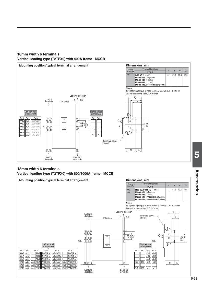
5-33
5
Accesso
ries
Vertical leading type (T2TFX0) with 400A frame MCCB
Mounting position/typical terminal arrangement Dimensions, mmFramesize (A)
Types of breakersA D
MCCB
Notes: 1) Tightening torque of M3.5 terminal screws: 0.9 – 1.2 N • m2) Applicable wire size: 2.0mm2 max
S400-ND (3 poles)PVS400-NDL (3/4 poles)PVS400-NDH (4 poles)PVS400-NNL (3 poles)PVS400-NNL, PVS400-NNH (4 poles)
33 75.5400
18mm width 6 terminals
B
51.5
Ex.1 Ex.2Ex.3Ex.1 Ex.2
57181818 A
BC
D
86.5
10
ON
OFF
LCLC
25 46 67
7 5.5
C2
C1
D2
D1
AXa3AXb3AXc3AXc2AXb2AXa2
ALa1ALb1ALc1AXc1AXb1AXa1
AXa2AXb2AXc2AXc1AXb1AXa1
ALa1ALb1ALc1AXc1AXb1AXa1
Left terminalarrangement
Right terminalarrangement
3/4 poles
Leading direction
Leading direction
Leading direction
Leading direction
Terminal cover (clear)
C
63.5
Vertical leading type (T2TFX0) with 800/1000A frame MCCB
Mounting position/typical terminal arrangement Dimensions, mmFramesize (A)
Types of breakersA D
MCCB
Notes: 1) Tightening torque of M3.5 terminal screws: 0.9 – 1.2 N • m2) Applicable wire size: 2.0mm2 max
S800-ND, S1000-ND (3 poles)PVS800-NDL (3/4 poles)PVS800-NNL (3 poles)PVS800-NDH, PVS800-NNL (4 poles)PVS800-GDH, PVS800-NNH (4 poles)
33 75.5800,1000
18mm width 6 terminals
B
51.5
Ex.1 Ex.2 Ex.3 Ex.4Ex.4 Ex.5Ex.3 Ex.6Ex.1 Ex.2
57 A
BC
D
29.5
ON
OFF
ASL
25 46 67
7 5.5
ASL
C2
C1
D2
D1
ALa2ALb2ALc2C2
C1
ALa2ALb2ALc2D2
D1
AXa3AXb3AXc3AXc2AXb2AXa2
ALa1ALb1ALc1AXc1AXb1AXa1
AXa4AXb4AXc4AXc3AXb3AXa3
AXa2AXb2AXc2AXc1AXb1AXa1
AXc3AXb3AXa3
AXa2AXb2AXc2AXc1AXb1AXa1
AXc4AXb4AXa4
AXa3AXb3AXc3AXc2AXb2AXa2
ALa1ALb1ALc1AXc1AXb1AXa1
AXa2AXb2AXc2AXc1AXb1AXa1
ALa1ALb1ALc1AXc1AXb1AXa1
86.5
18181818
Left terminalarrangement
Right terminalarrangement
Leading directionLeading direction
Leading direction
Leading direction
Terminal cover (clear)3/4 poles
C
63.5

5-34
Externally mounted accessories
5. Terminal blocks (TF)
Horizontal leading type (LTF) with 1250 to 3200A frame MCCB
ON
OFF
U2
U1
S2
S1
A9.
6×5
62
21
12
1
62
B
AXb3
AXa3
AXc3
AXb2
AXa2
AXc2
AXb1
AXa1
AXc1
ALb1
ALa1
ALc1
27.5 C
12.5
7.8
D
Ex. 1 Ex. 2
Left terminal arrangement
Ex. 3
Right terminal arrangement
M3.5✕0.7 screw
Mounting position/typical terminal arrangementFrame size
(A) Types of breakers A B
Dimensions, mm
C D
2000 XS2000ND 54 208 100 1152500 XS2500ND 54 208 100 115
Notes: 1) Values in parentheses applies to 4-pole breakers.2) Tightening torque of M3.5 terminal screws: 0.9 – 1.2 N.m3) Applicable wire size: 2.0mm2 max x 2
XS1250ND, XS1600ND
51 194 77 92
3200 XS3200ND 54 208 100 115
1250,1600

6-1
6
Ou
tline
Dim
ensio
ns
6DC Air Circuit Breakers Outline Dimensions
AR216S, AR220S 3P …………………………………………………………6-2AR325S, AR332S 3P …………………………………………………………6-4AR325-NDH 4P…………………………………………………………………6-6AR440S 3P ……………………………………………………………………6-8
DC Moulded Case Circuit Breakers Outline DimensionsS160-SD, S160-GD, S160-SDN, S250-SD, S250-GD, S250-SDN 3P …6-10S400-ND 3P …………………………………………………………………6-11S800-ND 3P …………………………………………………………………6-11S1000-ND 2P, 3P ……………………………………………………………6-12XS1250ND 2P, 3P ……………………………………………………………6-13XS1600ND 2P, 3P ……………………………………………………………6-14XS2000ND 2P, 3P ……………………………………………………………6-15XS2500ND, XS3200ND 2P, 3P ……………………………………………6-16PVE160-SDL 3P………………………………………………………………6-17PVS160-SDL, PVS250-SDL 3P ……………………………………………6-18PVS250-SNL 3P………………………………………………………………6-18PVS160-SDL, PVS250-SDL, PVS160-SNL, PVS250-SNL 4P …………6-19PVS160-GDH, PVS250-GDH 4P……………………………………………6-19PVS160-SDH, PVS250-SDH, PVS160-SNH, PVS250-SNH 4P ………6-20PVS400-NDL 3P………………………………………………………………6-21PVS400-NDL, PVS400-NDH 4P ……………………………………………6-21PVS400-NNL 3P………………………………………………………………6-22PVS400-NNL, PVS400-NNH 4P ……………………………………………6-22PVS800-NDL 3P………………………………………………………………6-23PVS800-NDL, PVS800-NDH 4P ……………………………………………6-23PVS800-NNL 3P………………………………………………………………6-24PVS800-NNL, PVS800-NNH 4P ……………………………………………6-24
OutlineDimensions

6-2
※1 : Conductors including connecting bolts should be separated min-7mm from Draw-out arm.
※2 : Panel cut should be 339 mm not 335 mm when the door flange is used.~~~~~~~~~~~~~~~~~~~~~~~~~~~~~~~~~~~~~~~~~~~~~~~~~~~~~~~~~~~
405
20
335※2
30
164
PC
PC
164
177 177
329
460
490
3342.5
50
120 120
141
94
4-ø14
23850
0
204 204
240 240
250
R116
158.5158.5rear panel cut
front panel cut
panel cut-out
For fitted with breaker fixing boltsdraw-out handle
Maintenancespace
Maintenancespace
Maintenancespace
Mounting holes
DC Air Circuit Breakers
¡Type AR216S 3P, AR220S 3P Draw-out type
Terminal size
Type t1○ t2○ t3○ W
AR216S 20 15 25 22.5
AR220S 20 15 25 ―
Outline dimensions (mm)

6-3
6
Ou
tline
Dim
ensio
ns
CP:ACB Front cover center line
3-ø11
345 100
40
445265
141
199
14 21
35AR216S AR220S
15
2525
2525W
W
94 110
100
35
15
WW
15.5
14.5
149
150.
5
204.
5
2525
14.5
15.5
2-ø11
345.
559
.5
345.
559
.5
18
85 85
42.5
9t2
40
125
107
85
6785
PC 299.
5
12
17
20
33 2548
.5
¶1
140
conductor overlap. max
Lifting hole 2-ø20
M8 screwearth terminal
CONNECTED position
TEST position
ISOLATED position
ON-OFF button cover
Control circuit terminal cover (optional)
Inter-pole barrier
Inter-pole barrier 1.6t
Inter-pole barrier 2t
Draw-out arm(comes out when breaker is drawn out)
AR216S 3P, AR220S 3P
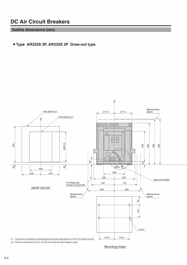
6-4
405
20
335※2
30
216
PC
PC
216
230 230
329
460
490
33
293 293
60
50
172.5 172.5
141
94
4-ø14
238
500
257 257
250
R116
211.5211.5rear panel cut
front panel cut
For fitted with breaker fixing bolts
draw-out handle
Maintenancespace
Maintenancespace
Maintenancespace
panel cut-out
Mounting holes
¡Type AR325S 3P, AR332S 3P Draw-out type
DC Air Circuit Breakers
※1 : Conductors including connecting bolts should be separated min-7mm from Draw-out arm.
※2 : Panel cut should be 339 mm not 335 mm when the door flange is used.~~~~~~~~~~~~~~~~~~~~~~~~~~~~~~~~~~~~~~~~~~~~~~~~~~~~~~~~~~~
Outline dimensions (mm)

6-5
6
Ou
tline
Dim
ensio
ns
CP:ACB Front cover center line
PC
PC
345 100
40
130 130
5
20
445265
141
199
14 21
35
15
12.5
12.5
2525
25
94 110
12.5
12.5
25 100
165
40
120
100
2525
65
18
9
406
345.
559
.5
120
142
161
109
120
204.
5
33 2548
.5
4-ø11
12
17
20
¶1
197.5
CONNECTED position
TEST position
ISOLATED position
ON-OFF button cover
Control circuit terminal cover (optional)
Inter-pole barrier
M8 screwearth terminal
conductor overlap. max
Inter-pole barrier 1.6t
Inter-pole barrier 2t
Lifting hole 2-ø20
Draw-out arm(comes out when breaker is drawn out)
AR325S 3P, AR332S 3P

6-6
405
20
335※2
30
216
PC
PC
336
230 350
329
460
490
33
293 413
60
50
172.5 292.5
141
94
4-ø14
238
500
257 377
250
R116
331.5211.5
panel cut-out
Mounting holes
rear panel cut
front panel cut
Maintenancespace
Maintenancespace
Maintenancespace
draw-out handleFor fitted with breaker fixing bolts
¡Type AR325-NDH 4P Draw-out type
DC Air Circuit Breakers
※1 : Conductors including connecting bolts should be separated min-7mm from Draw-out arm.
※2 : Panel cut should be 339 mm not 335 mm when the door flange is used.~~~~~~~~~~~~~~~~~~~~~~~~~~~~~~~~~~~~~~~~~~~~~~~~~~~~~~~~~~~
Outline dimensions (mm)
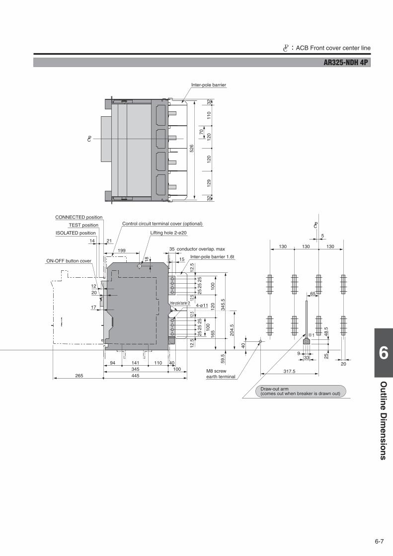
6-7
6
Ou
tline
Dim
ensio
ns
CP:ACB Front cover center line
PC
130 130 130
5
20
199
14 21
35
15
12.5
12.5
2525
25
12.5
12.5
25 100
165
40
120
100
2525
65
18
9
345.
559
.5
PC 120
120
110
3232
129
204.
5
33 2548
.5
4-ø11
12
17
20
345 100445265
14194 110 40
526
70
¶1
317.5
CONNECTED position
TEST position
ISOLATED position
ON-OFF button cover
Inter-pole barrier
Control circuit terminal cover (optional)
conductor overlap. max
Inter-pole barrier 1.6t
Inter-pole barrier 2t
M8 screwearth terminal
Lifting hole 2-ø20
Draw-out arm(comes out when breaker is drawn out)
AR325-NDH 4P

6-8
R11
6
42.5
238250
P
500
490
460
33
441164
405
20
335 ※2
C
329
50
30
PC
177 454
435.5158.5
240 517
204 481
draw-out handle
Maintenance space
panel cut-out
rear panel cut
front panel cut
For fitted with breaker fixing bolts
Maintenancespace
Maintenancespace
¡Type AR440S 3P Draw-out type
DC Air Circuit Breakers
※1 : Conductors including connecting bolts should be separated min-7mm from Draw-out arm.
※2 : Panel cut should be 339 mm not 335 mm when the door flange is used.~~~~~~~~~~~~~~~~~~~~~~~~~~~~~~~~~~~~~~~~~~~~~~~~~~~~~~~~~~~
Outline dimensions (mm)

6-9
6
Ou
tline
Dim
ensio
ns
CP:ACB Front cover center line
375
295 428
17
141 19394
120
397
12.5
2525 10
0
100
120
165
2512.5
12.5 25
2525
12.5
20
14 21
199
18
35
PC
PC
PC
40
42.548
.525
9
12
4-ø14
4-ø11
20
375
100
1515
50
181
181
¶1
417
345.
559
.5
576.
5
42.5
192
192
210
157.
517
5.5
204.
5
33Rear panel
Front panel
Control circuit terminal cover
CONNECTED position
TEST position
ISOLATED position
ON-OFF button cover40 conductor overlap. max
M8 screwearth terminal
Draw-out arm(comes out when breaker is drawn out)
Inter-pole barrier 1.6t
Inter-pole barrier 2t
Inter-pole barrier
Lifting hole 2-ø20
AR440S 3P

6-10
ASL : Arrangement Standard Line HL : Handle Frame Centre Line CL : Handle Centre LineDC Moulded Case Circuit Breakers
Outline dimensions (mm) S160-SD 3P, S160-GD 3P, S160-SDN 3P
Outline dimensions (mm) S250-SD 3P, S250-GD 3P, S250-SDN 3P
CL CL
LH LHLH
Front-connected
Rear-connected Drilling plan (front view)
M4✕0.7Tapped hole
M4✕0.7Mounting screw
Panel cutout (front view)Detail of connecting part
Mounting plate(max. t3.2)
Studs are horizontaldirection only
Panel cutout dimensions shown give an allowance of 1.0mm or more around the handle escutcheon.
✽ Straight bars only. For line side, use with the terminal cover.
With extension bars ✽ (optional)
Drilling plan (front view)
Preparation of conductor
25
50
C D
E
A
3P
111
114
ø20
37.5
3P
38.577
B
C D
A
B
102
52
114
68
102
F
95
3P
7.7
25 25
102
52
6.5(
max
.)
9(m
ax.)16.5(max.)
max.t514(max.)max.t5
ø5.5(25-40A)
ø9(63-160A)
ø5.5(25-40A)
ø9(63-160A)
45
CL CL CL CLCL
LH LH
LH
M4✕0.7Tapped hole
Terminal cover
M4✕0.7Mounting screw
M5✕0.8 screw (25-40A)M8 screw (63-160A)
257550
102
7.7
24
6661
60.3
9568
52
3P
10.5
3P
5013
0
111
3P
8.5
5.63
17
114
25 25
ø8.3
45
284
CL
LH
75
3P
5.3
130
665756
22
22
Terminal coverTerminal cover
Mounting hole
Mounting hole
48
Rated current (A) A B C D E25-40 10.5 6.5 4 13 1663-160 12.5 8.5 4 13 16
F45
CL CL CLCLCL
CL CL CL
LHLH
LH
CL
LH
LH
LH
LH
7
23
45
3P 3P
3P
3P
ø24
3513
9
7
102
144
144
206
126
ø9
6 3516
6860
10772 3535 35
3P
65.5
65.5
30.5
11.5
19
165
3535
102
5516
514
4
45 126
7 35
24
4610570
24 21
ø11
10.5 95
6860
284
22
3P
5.3
165
105
22
22
25(max.)max.t7
11(m
ax.)ø9
45
3P
Mounting hole
Terminal cover
Mounting holeTerminal cover
Terminal cover
Terminal cover
M8 screw
M4✕0.7Mounting screw
M4✕0.7Tapped hole
Conductoroverlap, max
Mounting hole
✽ Straight bars only. For line side, use with the terminal cover.
Drilling plan (front view)
M4✕0.7Tapped hole
M4✕0.7Mounting screw
Panel cutout (front view)Detail of connecting part
Mounting plate(max. t3.2)
Stud can be turned 45° or 90°
Panel cutout dimensions shown give an allowance of 1.0mm around the handle escutcheon.
Conductor overlap, max
52.5
53.5107
48
Preparation of conductor
With extension bars ✽ (optional)
Drilling plan (front view)
Front-connected
Rear-connected

6-11
6
Ou
tline
Dim
ensio
ns
ASL : Arrangement Standard Line HL : Handle Frame Centre Line CL : Handle Centre Line
Outline dimensions (mm) S800-ND 3P
HLHL
HL
HL
HL
ASL ASL
3P
ASL
3P
3P
ASL
ASL
ASL
103 107
28 13
4
145
70 70
13
70 70 43 43
117
1
26
10
42
122
1
03
30.
5
80.5
117
126
3P
ø13
ø48
127.5
R6
ø13
70
140 210
3P
172
40
13
70
80
273
8
0
92
55.
5 4
6.5
117
1
26
141
1
32
t2 L2
t1 L1
103 107
145
28 13
127.5 4
80.5
51
170
90
25
2532
20
158
8
32
L1 L2 t1
32 34 8
32 35 10
t2
8
10
630
800
Front-connected
Drilling plan (front view) Panel cutout (front view)
Drilling plan (front view)
Conductor overlap, max
Conductor overlap, max
Stud can be turned 90°
M8 Tapped hole
M8Mounting screw
Interpole barrier (removable)
Mounting hole
M8Mounting screw
Panel cutout dimensions shown give an allowance of 1.0mm around the handle escutcheon.Note: Studs are factory installed in horizontal direction both on the line and load sides.
Trip button (red)
ø15 for accessory wiring when necessary
Rated Current (A)
Toggle extension(removable)
Toggle extension(removable)
M8 Tapped hole
Rear-connected
Outline dimensions (mm) S400-ND 3P
CL
Drilling plan (front view) Panel cutout (front view)
Front-connected
Rear-connected
Panel cutout dimensions shown give an allowance of 1.0mm around the handle escutcheon.
Preparation of conductor
With extension bars (optional)
Drilling plan (front view)
M10 screw
M6Tapped hole
Interpole barrier (removable)
Interpole barrier (removable)Mounting hole
M6Mounting screw
(With handle cap)
On side 36Off side 35
Con
duct
or
over
lap
max
.
Con
duct
or
over
lap
max
.
M6Tapped hole
Mounting plateStud can be turned 45° or 90°
Note: Studs are factory installed in horizontal direction both on the line and load sides.
LH
LH
LH
90
116
51
85.3 14.7
8 36
8 35
4597
103107
127.5145
971031074
127.5145
4140
260
102
90
102
90
214
110
228
260
228
830
CLCL
CL
CL CL CL
12(m
ax.)
ø11
ø13
214
228
ø36
30(max.)
max. t10
3PLH
45
90
CL
CL
3PLH
118
92
R6
3P
30 45 45
103
11070
153915
39ø1
3
120
28
14.5
30 44.5
3014
.544
.5
ø14 148
44.5
349
260
Trip button (red)

6-12
ASL : Arrangement Standard Line HL : Handle Frame Centre Line CL : Handle Centre LineDC Moulded Case Circuit Breakers
Outline dimensions (mm) S1000-ND 2P, 3P
HL
HL
HL
HL
HL
3P
ASL
ASL
3P
ASL ASL
ASL
3P
ASLR6
ø1311
7
127.5
ø133P
45
ø51 3P
172
70
92
117
1
26
140 210
14 35
14 32
45
13
103 107
145
28 13
127.5 4
80
273
80
15
32 8
25
55.
5 4
6.5 90
141
1
32
80.5
110
103
107
28 13
4
145
70 70 43 43
25 8
32 20
103
117
1
26
30.
5
126
122
13
80.5
51
170
70 12
70 70
Toggle extension(removable)
Toggle extension(removable)
Drilling plan (front view) Panel cutout (front view)
Preparation of conductor Drilling plan (front view)Front-connected
Rear-connected
Conductor overlap, max
Conductor overlap, max
M8 Tapped hole
M8Tapped hole
M8Tapped hole
Interpole barrier (removable) Mounting hole
M8 Mounting screw
Panel cutout dimensions shown give an allowance of 1.0mm around the handle escutcheon.
Trip button (red)
ø15 for accessory wiring when necessary
Secured in vertical position only
Note: 2 poles breaker is same outline dimensions as 3 poles breaker.

6-13
6
Ou
tline
Dim
ensio
ns
ASL : Arrangement Standard Line HL : Handle Frame Centre Line CL : Handle Centre Line
Outline dimensions (mm) XS1250ND 2P, 3P
Front-connected
Rear-connected
Note: 2 poles breaker is same outline dimensions as 3 poles breaker.
Drilling plan (front view)
Conductor overlap, max
M8Mounting screw
Toggle extension(removable)
Mounting hole
Drilling plan (front view) Panel cutout (front view)
Conductor overlap, max
Mounting plate
M8 Mounting screw
Insulating plate
Panel cutout dimensions shown give an allowance of 1.5mm around the handle escutcheon.
ø15 for accessory wiring when necessary
Soft plastic tubing ø50 to be provided on center pole and neutral pole of vertical terminal type for insulation.
Mounting plate
Note: Studs are factory installed in horizontal direction both on the line and load sides.Please specify when ordering if vertical direction is reqired.

6-14
ASL : Arrangement Standard Line HL : Handle Frame Centre Line CL : Handle Centre LineDC Moulded Case Circuit Breakers
Outline dimensions (mm) XS1600ND 2P, 3P
Draw-out
Front-connected
Note: 2 poles breaker is same outline dimensions as 3 poles breaker.
Rear-connected
Drilling plan (front view)Breaker fixing screw
Mounting hole
300 (max.)
220
220
420
105
7550
2520
2512
020
70
100
170
190
2020
60
200
ø12 Mounting hole
Mounting angle
526 (draw-out)
396 (connected)
282316
395 (draw-out)
325 (disconnected)
ø12
ø12
1570
200 215
225
70
295 (test)265 (connected)
Draw-out handle(removable)
Auxiliary circuit terminals (Automatic connection)
Conductor overlap, maxConductor overlap, max
Conductor overlap, max
Con
duct
or
over
lap,
max
Mounting angle
( )ON side Center pole OFF side All poles
Insulation tube
Panel cutout dimensions shown give an allowance of 1.5mm around the handle escutcheon.
Panel cutout (front view)
Drilling plan (front view)
Drilling plan (front view)
M8Mounting screw
M8Mounting screw
Insulating plate
Mounting angle
Toggle extension(removable)
※Contact TERASAKI if manual connection is required.
※
Toggle extension(removable)
90°
3P

6-15
6
Ou
tline
Dim
ensio
ns
ASL : Arrangement Standard Line HL : Handle Frame Centre Line CL : Handle Centre Line
Outline dimensions (mm) XS2000ND 2P, 3P
90°
ø12
232
793030
105
302
3P
320320105 105
3065
38022560
20 1810
28.8130
340245
18510
160
95
20105 105
3030
302 ø12
105
7923
2
119
144
466371308
1325
160
9565
30
268
280
232
130
6530
3020
20
112
30
ø11
R10
ø11
15
314
105105
1520
2020
624
34334
310
405(max.)※
ASL
ASL
ASLASL
ASL
ASL
ASL
ASL
ø11
340(3P)
290(3P)
ø14
3P
LHLH
LH
LH
LHLH
450
9090
193
257
30 2015
20
250
5898
.5
1
1
ASL
LH
Draw-out
Front-connected
Rear-connected
Mounting angle
Mounting hole
M10 Mounting screw
M10 Mounting screw
Conductor overlap, max
Conductor overlap, max
Drilling plan (front view)
Toggle extension(removable)
Toggle extension(removable) Mounting angle
Drilling plan (front view) Panel cutout (front view)
Panel cutout dimensions shown give an allowance of 2mm around the handle escutcheon.
Mounting hole ø14
Conductor overlap, max
561(draw-out)
Draw-out toggle (removable)
Manual operating toggle (removable)
371(disconnected)341(test)
311(connected)Mounting hole
Mounting angle
Drilling plan (front view)
※Contact TERASAKI if manual connection is required.
Auxiliary circuit terminals (Automatic connection)
Note: 2 poles breaker is same outline dimensions as 3 poles breaker.

6-16
ASL : Arrangement Standard Line HL : Handle Frame Centre Line CL : Handle Centre LineDC Moulded Case Circuit Breakers
Outline dimensions (mm) XS2500ND 2P, 3P, XS3200ND 2P, 3P
ø14
ø12
450
30
257
19398
.558
232
793030
144
119
R10
105
302
113
178
90
40
320250
340
1
ASL ASL
ASL ASL
150245
105 10520
28.890
20 4020
18510
3P
LH
LHLH
裏面形Rear-connected
Mounting angle
Mounting angle
Mounting hole
M10 Mounting screw
Conductor overlap, max
Toggle extension(removable)
Panel cutout dimensions shown give an allowance of 2mm around the handle escutcheon.
Note: 2 poles breaker is same outline dimensions as 3 poles breaker.

6-17
6
Ou
tline
Dim
ensio
ns
ASL : Arrangement Standard Line HL : Handle Frame Centre Line CL : Handle Centre Line
Outline dimensions (mm) PVE160-SDL 3P
CL CL
LH LHLH
Front-connected
Rear-connected Drilling plan (front view)
M4✕0.7Tapped hole
M4✕0.7Mounting screw
Panel cutout (front view)Detail of connecting part
Mounting plate (max. t3.2)
Studs are horizontaldirection only
Panel cutout dimensions shown give an allowance of 1.0mm or more around the handle escutcheon.
✽ Straight bars only. For line and load side, use with the terminal covers.
With extension bars ✽ (optional)
Drilling plan (front view)
Preparation of conductor
Insulating plate
Insulating plate
25
50
C D
E
A
3P
111
114
ø20
37.5
3P
38.577
B
C D
A
B
100.450.4
114
69.6
102
F
96.6
3P
6.1
25 25
100.
450.4
6.5(
max
.)
9(m
ax.)16.5(max.)
max.t514(max.)max.t5
ø5.5(25-40A)
ø9(63-160A)
ø5.5(25-40A)
ø9(63-160A)45
CL CL CL CLCL
LH LH
LH
25
7550
50
102
6.1
25.6
67.6
96.6
53.669.6
3P
10.5
3P
5050
130
111
3P
8.5
5.63
17
114
25 25
ø8.3
45
29.64
CL
LH
75
3P
5.3
5.3
130
67.6
22
22
1.6t
Insulating plate
Insulating plate
48
1.6t
M4✕0.7Tapped hole
Terminal cover
M4✕0.7Mounting screw
M5✕0.8 screw (25-40A)M8 screw (63-160A)
Terminal coverTerminal cover
Mounting hole
Mounting hole
Rated current (A) A B C D E25-40 10.5 6.5 4 13 1663-160 12.5 8.5 4 13 16
F45

6-18
ASL : Arrangement Standard Line HL : Handle Frame Centre Line CL : Handle Centre LineDC Moulded Case Circuit Breakers
Outline dimensions (mm) PVS160-SDL 3P, PVS250-SDL 3P
CL CL CLCLCL
CL CL
LHLH
LH
CL
LH
LH
LH
CL
LH
5.4
23
3P 3P
3P
3P
ø24
3513
9
5.4
102
144
144
206
126
ø9
6 3516
69.661.6
70.496.6 105.4
3535 35
3P67.160.257.1
67.160.657.5
30.5
11.5
19
165
3535
102
5555
55
165
5516
514
4
45 126
35
25.6
47.61.6t
1.6t
10.5
10570
115
115
115
24 21
ø11
✽ Straight bars only. For line and load side, use with the terminal covers.96.6
69.610.561.6
29.64
22
3P
5.3
5.3
105
22
22
45
3P
Panel cutout dimensions shown give an allowance of 1.0mm around the handle escutcheon.
52.5
53.5107
48
Drilling plan (front view) Panel cutout (front view)
Preparation of conductor
With extension bars ✽ (optional) Drilling plan (front view) Front-connected
Rear-connected
Mounting hole
Insulating plate
Terminal cover
Insulating plate
M8 screw
Terminal cover
M4✕0.7Mounting screw
25(max.)max.t7
11(m
ax.)ø9
Insulating plate
Mounting hole
Conductoroverlap, max
Insulating plate
M4✕0.7Tapped hole
M4✕0.7Mounting screw
M4✕0.7Tapped hole
Insulating plate
Insulating plate
Mounting plate(max. t3.2)
Insulating plate
Stud can be turned 45° or 90°
Conductor overlap, max
Mounting hole
Terminal cover
Terminal cover
Outline dimensions (mm) PVS250-SNL 3P
CL CLCL
CL CL
LHLH
LH
CL
LH
LH
CL
LH
5.4
3P
3P
3P
ø24
3513
9
5.4
102
144
144
206
126
ø9
6 3516
69.661.6
70.496.6 105.4
3535 35
3P67.160.257.1
67.160.657.5
102
5555
55
165
5516
5
144
45 126
35
25.6
47.61.6t
1.6t
10.5
10570
115
115
24 21
96.669.610.561.6
22
3P
5.3
5.3
105
22
45
3P
Panel cutout dimensions shown give an allowance of 1.0mm around the handle escutcheon.
52.5
53.5107
48
Drilling plan (front view) Panel cutout (front view)
Preparation of conductor
Drilling plan (front view) Front-connected
Rear-connected
Mounting hole
Insulating plate
Terminal cover
Insulating plate
M8 screw
Terminal cover
M4✕0.7Mounting screw
25(max.)max.t7
11(m
ax.)ø9
M4✕0.7Tapped hole
M4✕0.7Mounting screw
M4✕0.7Tapped hole
Insulating plate
Insulating plate
Mounting plate(max. t3.2)
Insulating plate
Stud can be turned 45° or 90°
Conductor overlap, max
Mounting hole
Terminal cover
Terminal cover

6-19
6
Ou
tline
Dim
ensio
ns
ASL : Arrangement Standard Line HL : Handle Frame Centre Line CL : Handle Centre Line
Outline dimensions (mm) PVS160-SDL 4P, PVS250-SDL 4P, PVS160-SNL 4P, PVS250-SNL 4P
CL CL CLCLCL
CL CL
LHLH
LH
CL
LH
LH
LH
CL
LH
7
23
4P 4P
4P
4P
ø24
3513
9
7
102
144
144
206
126
ø9
6 3516
6860
7295 107
3535 35 35
4P65.558.657.1
65.559
57.5
30.5
11.5
1916
5
35 3535
102
5555
165
165
144
45 126
35
24
46
10.5
10535
140
10535
140
140
24 21
ø11
✽ Straight bars only. For line and load side, use with the terminal covers.95
6810.560
284
22
4P
2.3
5.3
5.3
22
22
25(max.)max.t7
11(m
ax.)ø9
45
Drilling plan (front view) Panel cutout (front view)
Preparation of conductor
With extension bars ✽ (optional) Drilling plan (front view)
4P
52.5
48
14253.5
Panel cutout dimensions shown give an allowance of 1.0mm around the handle escutcheon.
Front-connected
Rear-connected
Mounting hole
Terminal cover
M8 screw
M4✕0.7
Terminal cover
Mounting screw
Mounting hole
Conductoroverlap, max
M4✕0.7Tapped hole
Mounting plate(max. t3.2)
M4✕0.7Mounting screw
Stud can be turned 45° or 90°
Conductor overlap, max
Mounting hole
Terminal cover
Terminal cover
M4✕0.7Tapped hole
Outline dimensions (mm) PVS160-GDH 4P, PVS250-GDH 4P
CL
LH
CL
LH
LH
CL
LH
LH
CL
LH
CL
CL
5.4
4P
4P
3535 35
4P 4P
ø24
35
144
126
3535
5555
165
144
126
35
105
35
140
140
22
4P
2.3
5.3
5.3
22
4P
52.5
48
14253.5
Panel cutout dimensions shown give an allowance of 1.0mm around the handle escutcheon.
Drilling plan (front view) Panel cutout (front view)
Preparation of conductor
Drilling plan (front view)
67.160.657.5
102
45
25.6
47.61.6t
96.669.610.561.6
13
9
102
144
206
ø9
6 16
69.661.6
70.496.6 105.4
67.160.257.1
1.6t
10.5
24 21
45
5.4
325
240
325
240
165
Front-connected
Rear-connected
Mounting hole
Terminal cover
M4✕0.7Tapped hole
M4✕0.7Mounting screw
Mounting hole
Terminal cover
M4✕0.7Tapped hole
Insulating plate
Insulating plate
Insulating plate
M8 screw
Terminal cover
M4✕0.7Mounting screw
25(max.)max.t7
11(m
ax.)ø9
Mounting plate(max. t3.2)
Insulating plate
Stud can be turned 45° or 90°
Conductor overlap, max
Terminal cover Insulating plate

6-20
ASL : Arrangement Standard Line HL : Handle Frame Centre Line CL : Handle Centre LineDC Moulded Case Circuit Breakers
Outline dimensions (mm) PVS160-SNH 4P, PVS250-SNH 4P
CL CL CL
LH
CL
LH
LH
CL
LH
LH
LH
CL
LH
CL
CL
23
5.4
4P 4P
4P
3535 35
4P 4P
ø24
35
144
126
3535
30.5
11.5
1916
5
35 3535
5555
5555
165
165
144
126
35
10535
140
140
ø11
22
4P
2.3
5.3
5.3
22
22
4P
52.5
48
14253.5
Panel cutout dimensions shown give an allowance of 1.0mm around the handle escutcheon.
Drilling plan (front view) Panel cutout (front view)
Preparation of conductor
Drilling plan (front view)
67.160.657.5
102
45
25.6
47.61.6t
96.669.610.561.6
29.64
13
9
102
144
206
ø9
6 16
69.661.6
70.496.6 105.4
67.160.257.1
1.6t
10.5
24 21
45
5.4
With extension bars ✽ (optional)
✽ Straight bars only. For line and load side, use with the terminal covers.
166
166
166
Front-connected
Rear-connected
Mounting hole
Terminal cover
Mounting hole
Conductoroverlap, max
M4✕0.7Tapped hole
M4✕0.7Mounting screw
Mounting hole Terminal cover
M4✕0.7Tapped hole
Insulating plate
Insulating plate
Insulating plateInsulating plate
M8 screw
Terminal cover
M4✕0.7Mounting screw
25(max.)max.t7
11(m
ax.)ø9
Insulating plate
Mounting plate(max. t3.2)
Insulating plate
Stud can be turned 45° or 90°
Conductor overlap, max
Terminal cover Insulating plate
Outline dimensions (mm) PVS160-SDH 4P, PVS250-SDH 4P
CL CL CL
LH
CL
LH
LH
CL
LH
LH
LH
CL
LH
CL
CL
23
5.4
4P4P
4P
3535 35
4P 4P
ø24
35
144
126
3535
30.5
11.5
1916
5
35 353555
55
6565
165
165
144
126
35
10535
140180
140180
180
ø11
22
4P
2.3
5.3
5.3
22
22
4P
52.5
48
14253.5
Panel cutout dimensions shown give an allowance of 1.0mm around the handle escutcheon.
Drilling plan (front view) Panel cutout (front view)
Preparation of conductor
Drilling plan (front view)
67.160.657.5
102
45
25.6
47.61.6t
96.669.610.561.6
29.6
4
13
9
102
144
206
ø9
6 16
69.661.6
70.496.6 105.4
67.160.257.1
1.6t
10.5
24 21
45
5.4
With extension bars ✽ (optional)
✽ Straight bars only. For line and load side, use with the terminal covers.
1010 180
Front-connected
Rear-connected
Mounting hole
Terminal cover
Mounting hole
Conductoroverlap, max
M4✕0.7Tapped hole
M4✕0.7Mounting screw
Mounting hole Terminal cover
M4✕0.7Tapped hole
Insulating plate
Insulating plate
Insulating plateInsulating plate
M8 screw
Terminal cover
M4✕0.7Mounting screw
25(max.)max.t7
11(m
ax.)ø9
Insulating plate
Mounting plate(max. t3.2)
Insulating plate
Stud can be turned 45° or 90°
Conductor overlap, max
Terminal cover Insulating plate

6-21
6
Ou
tline
Dim
ensio
ns
ASL : Arrangement Standard Line HL : Handle Frame Centre Line CL : Handle Centre Line
Outline dimensions (mm) PVS400-NDL 4P, PVS400-NDH 4P
CL CL
CL
CL CL CL CL
HL
L
HL
HL
HL
H
4P
4P
260
86.998.6
8
214
104.6
228
90102
116
13.1
110
45
45 4570 115
51
129.1146.645
185
3014
.544
.530(max.)12
ø14
8
ø11
420
60 6060 60 60
126.581.5
14.5
30 44.5
349
260
118
92
R6
36.598.68
90102
104.6
228
260
830
ø13
129.1
30 45 45 45
104.
610
8.4
68.4
153915
39
214
45
228
45 45 45
ø36ø1
3
(max
.)
52.5
1.6t
37.68
1.6t
36.6
100
146.6
Interpole barrier(removable)
Mounting hole
Insulating plate
Insulating plate
ON side : 37.6OFF side : 36.6
M10 screw
M6Mounting screw
Trip button (red)
M6Tapped hole
Con
duct
or
over
lap,
max
Con
duct
or
over
lap,
max
Stud can be turned 45° or 90°
Mounting plate
Insulating plate
Insulating plate
Interpole barrier
M6Tapped hole
Drilling plan (front view) Panel cutout (front view)
Preparation of conductor With extension bars (optional) Drilling plan (front view)
Panel cutout dimensions shown give an allowance of 1.0mm around the handle escutcheon.
Front-connected
Rear-connected
Note: See section 4 for the installation of the insulating plate.
Note: Studs are factory installed in horizontal direction both on the line and load sides.See section 4 for the installation of the insulating plate.
Outline dimensions (mm) PVS400-NDL 3P
CL CL
CL
CL CL CL CL
HL
L
HL
HL
HL
H
3P
3P
260
86.998.6
8
214
104.6
228
90102
116
13.1
110
45
90
51
129.1146.6
140
3014
.544
.530(max.)12
8
ø11
416
60 60
120148
14.5
30 44.5
349
260
118
92
R6
98.68
90102
104.6
228
260
830
ø13
129.1
30 45 45
108.
4
68.4
153915
39
214
4522
8
45 45
ø36
104.
6
ø13
(max
.)
1.6t
37.68
1.6t
36.6
100
ø14
146.6
Front-connected
Rear-connected
Interpole barrier(removable)
Mounting hole
Insulating plate
Insulating plate
ON side : 37.6OFF side : 36.6
M10 screw
M6Mounting screw
M6Tapped hole
Con
duct
or
over
lap,
max
Con
duct
or
over
lap,
max
Stud can be turned 45° or 90°
M6Tapped hole
Mounting plate
Insulating plate
Insulating plate
Interpole barrier
Drilling plan (front view) Panel cutout (front view)
Preparation of conductor With extension bars (optional) Drilling plan (front view)
Panel cutout dimensions shown give an allowance of 1.0mm around the handle escutcheon.
Note: See section 4 for the installation of the insulating plate.
Note: Studs are factory installed in horizontal direction both on the line and load sides.See section 4 for the installation of the insulating plate.
Trip button (red)

6-22
ASL : Arrangement Standard Line HL : Handle Frame Centre Line CL : Handle Centre LineDC Moulded Case Circuit Breakers
Outline dimensions (mm) PVS400-NNL 4P, PVS400-NNH 4P
CL CL CL CL
HL
L
HL
H
4P
HLHL4P
CL
CL
CL
260
85.397
8
214
103
228
90102
116
14.7
110 368
45
45 4570 115
51
127.514545
185
3014
.544
.530(max.)12
ø14
358
ø11
60 60 60126.581.5
14.5
30 44.5
349
260
(max
.)
52.5
30 45 45 45
103
11070
153915
39
214
45
228
45 45 45
ø36
ø13
118
92
R6
36.5978
90102
103
228
260
830
ø13
127.5145
Front-connected
Rear-connected
Interpole barrier(removable)
Mounting hole
ON side : 36OFF side : 35
M10 screw
M6Mounting screw
Trip button (red)
M6Tapped hole
Con
duct
or
over
lap,
max
Con
duct
or
over
lap,
max
Stud can be turned 45° or 90°
Mounting plate
Interpole barrier
M6Tapped hole
Drilling plan (front view) Panel cutout (front view)
Preparation of conductor With extension bars (optional) Drilling plan (front view)
Note: See section 4 for the installation of the insulating plate.
Note: Studs are factory installed in horizontal direction both on the line and load sides.See section 4 for the installation of the insulating plate.
Panel cutout dimensions shown give an allowance of 1.0mm around the handle escutcheon.
Outline dimensions (mm) PVS400-NNL 3P
260
85.397
8
214
103
228
90102
116
14.7
110 368
45
90
51
127.5145
140
3014
.544
.525(max.)12
ø14
358
ø11
110
120148
14.5
30 44.5
44.5
349
260
(max.)
978
90102
103
228
260
830
ø13
127.5
30 45 45
103
11070
153915
39
214
4522
8
45 45
ø36
ø13
145
118
92
R6
CL CLCL CL
HL HL
HL
3P
CL
HL HLHL3P
CL
Front-connected
Rear-connected
Interpole barrier(removable)
Mounting hole
ON side : 36OFF side : 35
M10 screw
M6Mounting screw
Trip button (red)
M6Tapped hole
Con
duct
or
over
lap,
max
Con
duct
or
over
lap,
max
Stud can be turned 45° or 90°
Mounting plate
Interpole barrier
M6Tapped hole
Drilling plan (front view) Panel cutout (front view)
Preparation of conductor With extension bars (optional) Drilling plan (front view)
Note: See section 4 for the installation of the insulating plate.
Note: Studs are factory installed in horizontal direction both on the line and load sides.See section 4 for the installation of the insulating plate.
Panel cutout dimensions shown give an allowance of 1.0mm around the handle escutcheon.

6-23
6
Ou
tline
Dim
ensio
ns
ASL : Arrangement Standard Line HL : Handle Frame Centre Line CL : Handle Centre Line
Outline dimensions (mm) PVS800-NDL 3P
HL
HLHL
HL
HL
ASLASL ASL
ASLASL ASL
172
92
104.6 8
146.6
70 70
13
70 70 43 43
117
1
26
10
120
.4 1
04.6
20
32
25
30.
5
80.5
117
126
R6
ø13
8
ø48
129.1
ø13
70
42
1.6t
29.6 11.4
1.6t
140
210 60 60
t2 L2
70
40
13
104.6
146.6 129.1
8
80
273
8
0
15
32 8
25
55.
5 4
6.5
110
513
160
80
117
1
26
141
1
32
80.5
170
51
90
t1 L1
29.6 11.4
L1
630 (400-630)
800 (500-800)
L2 t1
33.6 35.6 8
33.6 36.6 10
t2
8
10
3P
3P
Front-connected
Rear-connected
Interpole barrier(removable) Mounting hole
Toggle extension(removable)
Mounting hole
Insulating plate
Insulating plate
Insulating plate
Insulating plate
M8Mounting screw
M8Tapped hole
Trip button (red)
Conductor overlap, max
Rated Current (A)
Conductor overlap, max
Stud can be turned 90°
M8Tapped hole
Interpole barrier
M8Mounting screw
Mounting plate
ø15 for accessory wiring when necessary
Toggle extension(removable)
Drilling plan (front view) Panel cutout (front view)
Drilling plan (front view)
Panel cutout dimensions shown give an allowance of 1.0mm around the handle escutcheon.
Note: See section 4 for the installation of the insulating plate.
Note: Studs are factory installed in horizontal direction both on the line and load sides.See section 4 for the installation of the insulating plate.
Outline dimensions (mm) PVS800-NDL 4P, PVS800-NDH 4P
HL
HLHL
HL
HL
ASLASL ASL
ASLASL ASL
172
92
104.6 8
146.6
70 70 70
13
70 70 70 43 43
117
1
26
10
120
.4
104
.6
20
32
25
30.
5
80.5
117
126
R6
ø13
8
ø48
129.1
ø13
70
42
1.6t
29.6 11.4
1.6t
70 70 70
105 175
280 60 60
t2 L2
70
40
13
104.6
146.6 129.1
8
80
273
8
0
15
32 8
25
55.
5 4
6.5
110
513
117
1
26
141
1
32
80.5
170
51
90
t1 L1
29.6 11.4
L1 L2 t1
33.6 35.6 8
33.6 36.6 10
t2
8
10
630 (400-630)
800 (500-800)
4P
4P
Interpole barrier(removable)
Mounting hole
Insulating plate
Trip button (red)
Conductor overlap, max
Mounting hole
Insulating plate
M8Mounting screw
Toggle extension(removable)
M8Tapped hole
Rated Current (A)
M8Mounting screw
Mounting plate
Insulating plate
Stud can be turned 90°
Interpole barrier
Toggle extension(removable)
Insulating plate
Conductor overlap, max
M8Tapped hole
ø15 for accessory wiring when necessary
Drilling plan (front view) Panel cutout (front view)
Drilling plan (front view)
Panel cutout dimensions shown give an allowance of 1.0mm around the handle escutcheon.
Note: See section 4 for the installation of the insulating plate.
Note: Studs are factory installed in horizontal direction both on the line and load sides.See section 4 for the installation of the insulating plate.
Front-connected
Rear-connected

6-24
ASL : Arrangement Standard Line HL : Handle Frame Centre Line CL : Handle Centre LineDC Moulded Case Circuit Breakers
Outline dimensions (mm) PVS800-NNL 3P
L1 L2 t1
32 34 8
32 35 10
t2
8
10
630 (400-630)
800 (500-800)
Front-connected
Rear-connected
Interpole barrier(removable)
Mounting hole
Trip button (red)
Conductor overlap, max
M8Mounting screw
Toggle extension(removable)
Rated Current (A)
M8Tapped hole
Drilling plan (front view)
M8Mounting screwM8Mounting screw
Conductor overlap, max
M8Tapped hole
ø15 for accessory wiring when necessary
Drilling plan (front view) Panel cutout (front view)
Panel cutout dimensions shown give an allowance of 1.0mm around the handle escutcheon.
Note: Studs are factory installed in horizontal direction both on the line and load sides.See section 4 for the installation of the insulating plate.
Note: See section 4 for the installation of the insulating plate.
Stud can be turned 90°Stud can be turned 90°
Toggle extension(removable)
Interpole barrier
Mounting plate
ASLASL ASL
ASLASL ASL
3P
3P
HL
HLHL
HL
HL
172
92
103
28 13
8
145
70 70
13
70 70 43 43
117
1
26
127
136
55
10
122
1
03
20
32
25
30.
5
80.5
117
126
R6
ø13
8
ø48
127.5
ø13
70
42
70 70
105 105
210
t2 L2
t1 L1
70
40
13
103
145
28 13
127.5 8
80
273
8
0
15
32 8
25
55.
5 4
6.5
110
117
1
26
141
1
32
80.5
170
51
90
Outline dimensions (mm) PVS800-NNL 4P, PVS800-NNH 4P
HL
HLHL
HL
HL
70 70 70
105 175
280
t2 L2
t1 L1
70
40
13
103
145
28 13
127.5 8
80
273
8
0
15
32 8
25
55.
5 4
6.5
110
117
1
26
141
1
32
80.5
170
51
90
L1 L2 t1
32 34 8
32 35 10
t2
8
10
630 (400-630)
800 (500-800)
Front-connected
Rear-connected
Interpole barrier(removable)
Mounting hole
Trip button (red)
Conductor overlap, max
M8Mounting screw
Toggle extension(removable)
Rated Current (A)
M8Tapped hole
Drilling plan (front view)
M8Mounting screw
Stud can be turned 90°
M8Mounting screw
Stud can be turned 90°
Toggle extension(removable)
Conductor overlap, max
M8Tapped hole
ø15 for accessory wiring when necessary
Drilling plan (front view) Panel cutout (front view)
Panel cutout dimensions shown give an allowance of 1.0mm around the handle escutcheon.
Note: Studs are factory installed in horizontal direction both on the line and load sides.See section 4 for the installation of the insulating plate.
Note: See section 4 for the installation of the insulating plate.
Interpole barrier
ASLASL ASL
ASLASL ASL
4P
4P
172
92
103
28 13
8
145
70 70 70
13
70 70 70 43 43
117
1
26
10
122
1
03
20
32
25
30.
5
80.5
117
126
R6
ø13
8
ø48
127.5
ø13
70
42

Air Circuit Breakers Moulded Case Circuit Breakers
Air Circuit Breakers Moulded Case Circuit BreakersDCDC
Ratings and specifications are subject to change without notice.
CAT REF. ’17-I73E
TERASAKI ELECTRIC CO., LTD.Head Office: 6-13-47 Kamihigashi, Hirano-ku, Osaka 547-0002, JapanCircuit Breaker Division: 6-13-47 Kamihigashi, Hirano-ku,
Osaka 547-0002, Japan
TEL +81-6-6791-2763FAX +81-6-6791-2732
[email protected]://www.terasaki.co.jp/
TERASAKI ELECTRIC (M) SDN, BHD.Lot 3, Jalan 16/13D, 40000 Shah Alam, Selangor DarulEhsan, Malaysia
TEL +60-3-5549-3820FAX +60-3-5549-3960
TERASAKI ELECTRIC TRADING & SERVICES (M)SDN. BHD.No. 20 & 22, Jalan Rajawali 2, Bandar Puchong Jaya, Jalan Puchong, 47100 Selangor Darul Ehsan, Malaysia
TEL +60-3-8070-2486, +60-3-8075-1542FAX +60-3-8070-2481
TERASAKI DO BRASIL LTDA.Rua Olof Palme, No. 765, Barra da Tijuca - Rio de Janeiro, Brazil
TEL +55-21-3301-9898FAX +55-21-3301-9861
[email protected]://www.terasaki.com.br
TERASAKI ELECTRIC (CHINA) LTD.72 Pacific Industrial Park, Xin Tang Zengcheng,Guangzhou 511340, China
TEL +86-20-8270-8556FAX +86-20-8270-8586
TERASAKI ELECTRIC GROUP SHANGHAIREPRESENTATIVE OFFICERoom No. 1405-6, Tomson Commercial Building710 Dong Fang Road, Pudong, Shanghai, 200122, China
TEL +86-21-58201611FAX +86-21-58201621
TERASAKI ELECTRIC (EUROPE) LTD.80 Beardmore Way, Clydebank Industrial EstateClydebank, Glasgow, G81 4HT, Scotland (UK)
TEL +44-141-941-1940FAX +44-141-952-9246
[email protected]://www.terasaki.com/
TERASAKI ELECTRIC (EUROPE) LTD. FILIALE ITALIAVia Ambrosoli, 4A-20090 Rodano, Milano, Italy
TEL +39-02-92278300FAX +39-02-92278320
[email protected]://www.terasaki.it/
TERASAKI ELECTRIC (EUROPE) LTD. SUCURSAL EN ESPAÑAPol. Ind. Coll de la Manya, C/Cal Ros dels Ocells 5-7,08403 Granollers, Barcelona, Spain
TEL +34-93-879-60-50FAX +34-93-870-39-05
[email protected]://www.terasaki.es/
TERASAKI ELECTRIC (EUROPE) LTD. FILIAL SVERIGEBox 2082 SE-128 22 Skarpnäck Sweden
TEL +46-8-556-282-30FAX +46-8-556-282-39
[email protected]://www.terasaki.se/
TERASAKI CIRCUIT BREAKERS (S) PTE. LTD.17 Tuas Street Singapore 638454
TEL +65-6744-9752FAX +65-6748-7592