DCC Wiring NMRA - QStation - Modeling from the Prototypeatsf93.qstation.org/Wiring.pdf · • GOOD:...
55
Version 5.1 1 DCC Wiring Mark Gurries DCC Layout Wiring By Mark Gurries Presentations for NMRA & PCR Conventions V 5.1 April 2009 Free copies of this presentation can be found at: http://www.siliconvalleylines.com
Transcript of DCC Wiring NMRA - QStation - Modeling from the Prototypeatsf93.qstation.org/Wiring.pdf · • GOOD:...
Version 5.1 1 DCC Wiring Mark Gurries
DCC Layout Wiring
By Mark Gurries
Presentations for NMRA & PCR Conventions V 5.1 April 2009
Free copies of this presentation can be found at: http://www.siliconvalleylines.com

DCC Wiring Mark Gurries Version 5.1 2
Other DCC Clinics
www.siliconvalleylines.com
DCC Wiring Mark Gurries Version 5.1 3
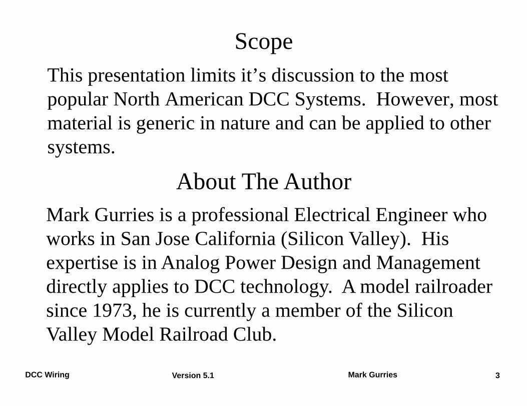
Scope This presentation limits it’s discussion to the most popular North American DCC Systems. However, most material is generic in nature and can be applied to other systems.
About The Author Mark Gurries is a professional Electrical Engineer who works in San Jose California (Silicon Valley). His expertise is in Analog Power Design and Management directly applies to DCC technology. A model railroader since 1973, he is currently a member of the Silicon Valley Model Railroad Club.
Version 5.1 4 DCC Wiring Mark Gurries
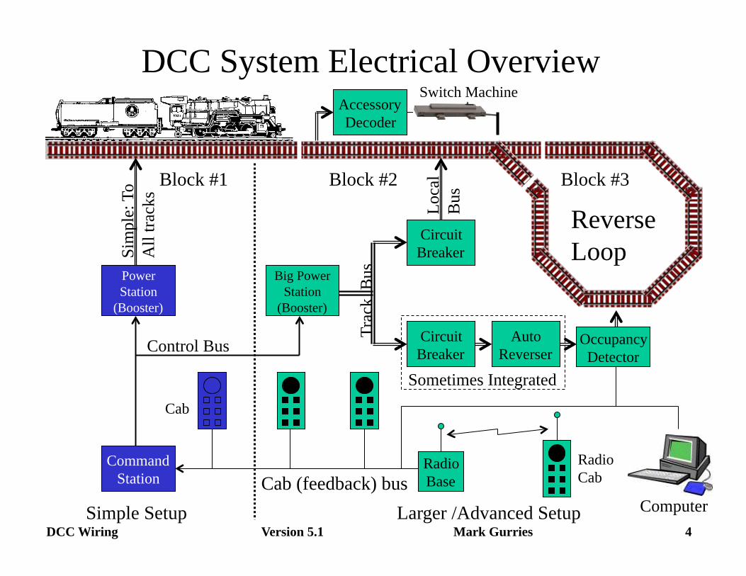
DCC System Electrical Overview
Power Station
(Booster)
Big Power Station
(Booster)
Command Station
Accessory Decoder
Occupancy Detector
Circuit Breaker
Circuit Breaker
Auto Reverser
Larger /Advanced Setup Simple Setup
Radio Base
Radio Cab
Switch Machine
Control Bus
Cab (feedback) bus
Trac
k B
us
Loca
l Bu
s Block #1 Block #2 Block #3
Computer
Cab Sometimes Integrated
Sim
ple:
To
All
track
s
Reverse Loop
Version 5.1 5 DCC Wiring Mark Gurries
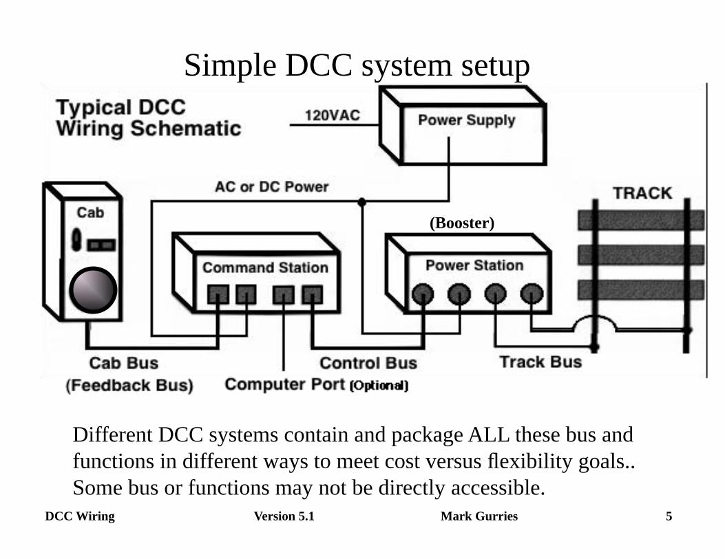
Simple DCC system setup
(Booster)
Different DCC systems contain and package ALL these bus and functions in different ways to meet cost versus flexibility goals.. Some bus or functions may not be directly accessible.
Version 5.1 6 DCC Wiring Mark Gurries
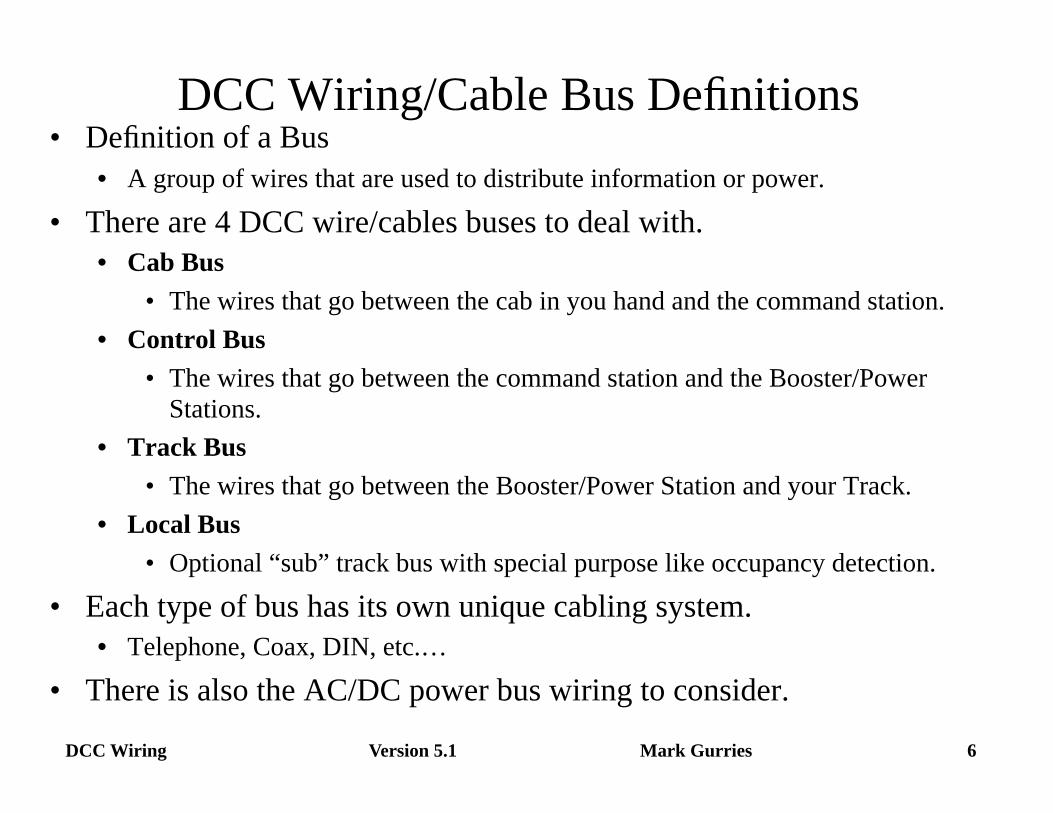
DCC Wiring/Cable Bus Definitions • Definition of a Bus
• A group of wires that are used to distribute information or power.
• There are 4 DCC wire/cables buses to deal with. • Cab Bus
• The wires that go between the cab in you hand and the command station. • Control Bus
• The wires that go between the command station and the Booster/Power Stations.
• Track Bus • The wires that go between the Booster/Power Station and your Track.
• Local Bus • Optional “sub” track bus with special purpose like occupancy detection.
• Each type of bus has its own unique cabling system. • Telephone, Coax, DIN, etc.…
• There is also the AC/DC power bus wiring to consider.
Version 5.1 7 DCC Wiring Mark Gurries
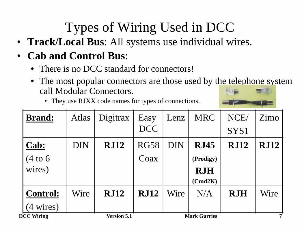
Types of Wiring Used in DCC • Track/Local Bus: All systems use individual wires. • Cab and Control Bus:
• There is no DCC standard for connectors! • The most popular connectors are those used by the telephone system
call Modular Connectors. • They use RJXX code names for types of connections.
Brand: Atlas Digitrax Easy DCC
Lenz MRC NCE/ SYS1
Zimo
Cab: (4 to 6 wires)
DIN RJ12 RG58 Coax
DIN RJ45 (Prodigy) RJH
(Cmd2K)
RJ12 RJ12
Control: (4 wires)
Wire RJ12 RJ12 Wire N/A RJH Wire
Version 5.1 8 DCC Wiring Mark Gurries
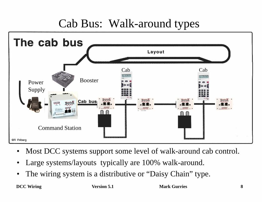
Cab Bus: Walk-around types
• Most DCC systems support some level of walk-around cab control. • Large systems/layouts typically are 100% walk-around. • The wiring system is a distributive or “Daisy Chain” type.
Cab Cab
Command Station
Power Supply
Booster
Version 5.1 9 DCC Wiring Mark Gurries
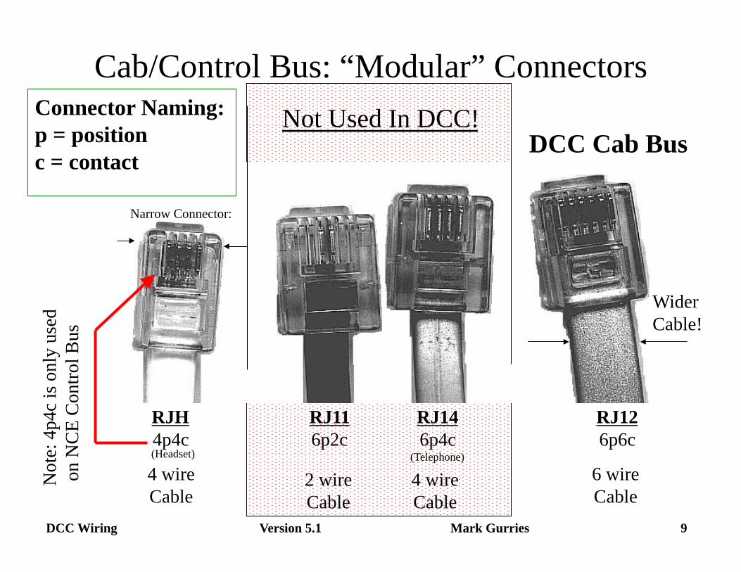
Cab/Control Bus: “Modular” Connectors
RJH 4p4c
RJ11 6p2c
RJ14 6p4c
(Telephone)
RJ12 6p6c
6 wire Cable
4 wire Cable
2 wire Cable
4 wire Cable
Not
e: 4
p4c
is on
ly u
sed
on
NCE
Con
trol B
us
DCC Cab Bus Not Used In DCC!
(Headset)
Wider Cable!
Connector Naming: p = position c = contact
Narrow Connector:
Version 5.1 10 DCC Wiring Mark Gurries
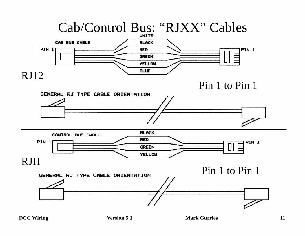
Cab/Control Bus: “RJ” Cable Wiring • ALL cables should be Pin to Pin (Pin1 to Pin1)
Do not use a pre-wired telephone cable found at most stores!! • Almost ALL have a reverse pin-out (Example: Pin1 to Pin6)
Only use cables specifically labeled for “Computer” or “Data”. Many major internet DCC stores sell cable made to order.
• There are two types of connectors: Stranded & Solid. Very difficult to tell by just looking at the connectors.
Stranded is the most common connector type (along with the wire) Solid is used in commercial (CAT-5 type) installations.
MESSAGE: Use the right connector with the right wire!
Version 5.1 11 DCC Wiring Mark Gurries
Cab/Control Bus: “RJXX” Cables
RJ12
RJH
Pin 1 to Pin 1
Pin 1 to Pin 1
Version 5.1 12 DCC Wiring Mark Gurries
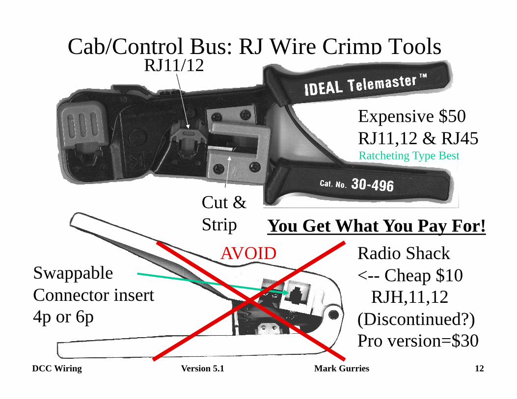
Cab/Control Bus: RJ Wire Crimp Tools
Expensive $50 RJ11,12 & RJ45
RJ11/12
Cut & Strip
Radio Shack <-- Cheap $10 RJH,11,12 (Discontinued?) Pro version=$30
Swappable Connector insert 4p or 6p
AVOID
Ratcheting Type Best
You Get What You Pay For!
Version 5.1 13 DCC Wiring Mark Gurries
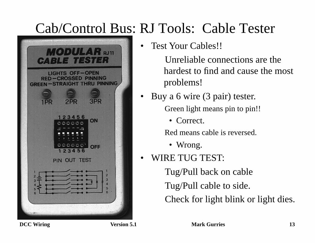
Cab/Control Bus: RJ Tools: Cable Tester • Test Your Cables!!
Unreliable connections are the hardest to find and cause the most problems!
• Buy a 6 wire (3 pair) tester. Green light means pin to pin!!
• Correct. Red means cable is reversed.
• Wrong. • WIRE TUG TEST:
Tug/Pull back on cable Tug/Pull cable to side. Check for light blink or light dies.
Version 5.1 14 DCC Wiring Mark Gurries
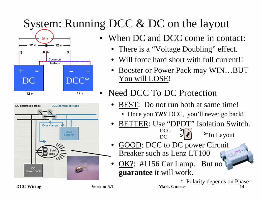
System: Running DCC & DC on the layout
DC DCC* + - - +
* Polarity depends on Phase
• When DC and DCC come in contact: • There is a “Voltage Doubling” effect. • Will force hard short with full current!! • Booster or Power Pack may WIN…BUT
You will LOSE!
• Need DCC To DC Protection • BEST: Do not run both at same time!
• Once you TRY DCC, you’ll never go back!! • BETTER: Use “DPDT” Isolation Switch.
• GOOD: DCC to DC power Circuit Breaker such as Lenz LT100
• OK?: #1156 Car Lamp. But no guarantee it will work.
DCC DC To Layout
Version 5.1 15 DCC Wiring Mark Gurries
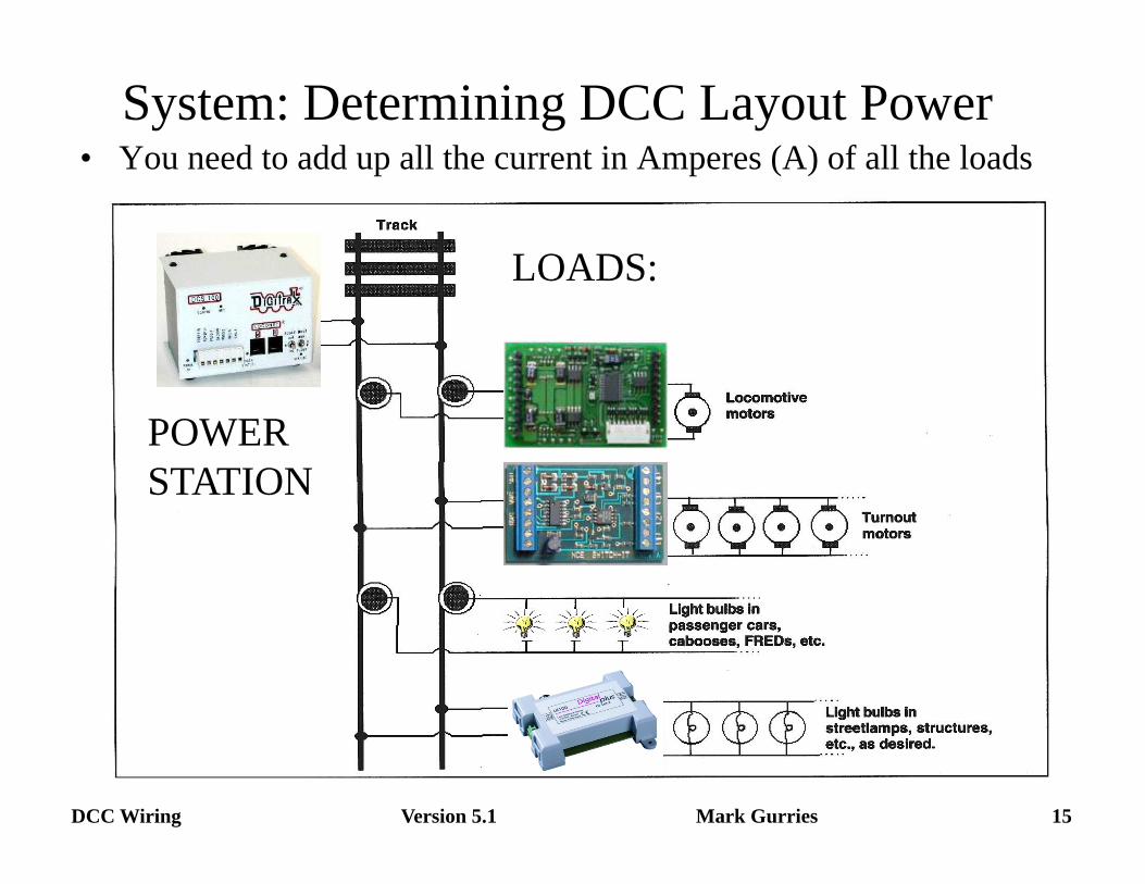
System: Determining DCC Layout Power • You need to add up all the current in Amperes (A) of all the loads
LOADS:
POWER STATION
Version 5.1 16 DCC Wiring Mark Gurries
System: Determining DCC Layout Power • Only needed for large layouts that can run lots of trains.
• Most “Starter System” have enough power for typical layouts! • Procedure to figure out your power budget:
• 1) Add up total maximum engine current. • Determine maximum number of simultaneous operating engines. • Determine motor current per engine.
– Don’t know? Use: N=1/2Amp, HO=3/4Amp, S=1.5Amp, O = 4Amps
• 2) Add up total maximum rolling stock accessory current. • Determine maximum current for all lighted passenger cars or cabooses. • Determine current for each car.
– Don’t Know? 14V bulb = 30mA/Each, LED’s = 20mA/Each,
• 3) Add up total maximum Stationary accessory current. • Determine maximum current for Switch Machines, Signals & Building Lights.
• 4) Divide the total current by the booster current rating to figure out the number of boosters you will need.
Version 5.1 17 DCC Wiring Mark Gurries
System: Determining DCC Layout Power (Example)
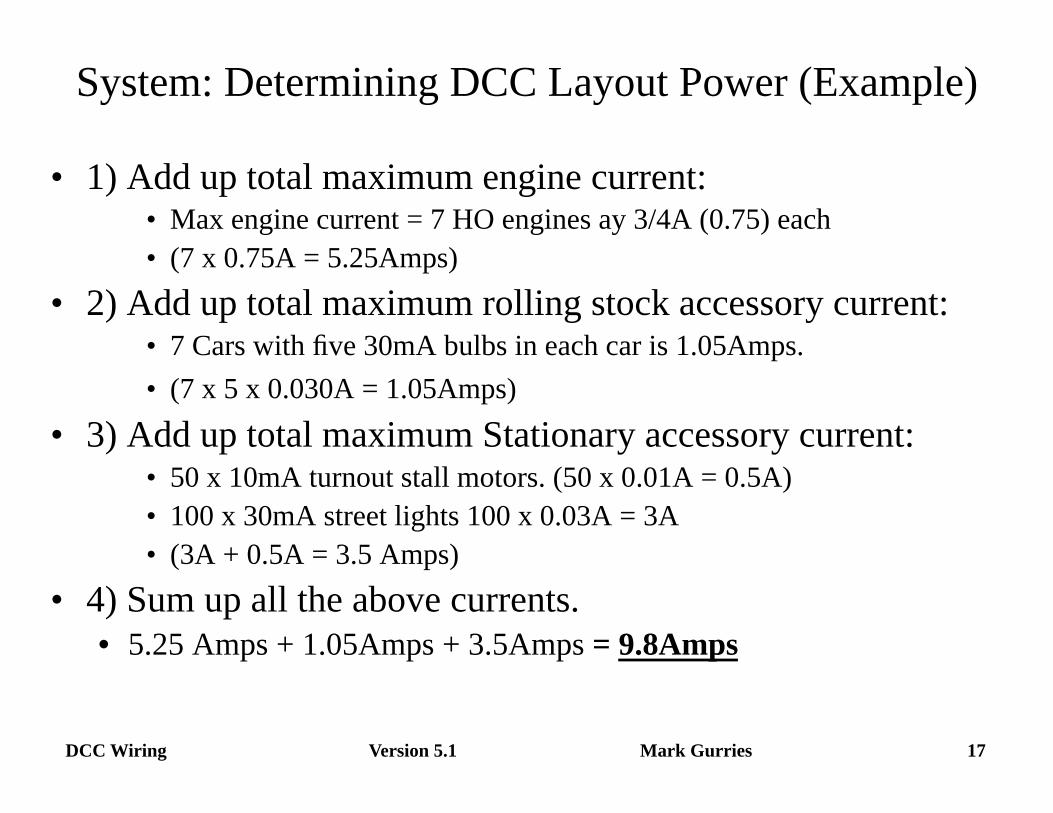
• 1) Add up total maximum engine current: • Max engine current = 7 HO engines ay 3/4A (0.75) each • (7 x 0.75A = 5.25Amps)
• 2) Add up total maximum rolling stock accessory current: • 7 Cars with five 30mA bulbs in each car is 1.05Amps. • (7 x 5 x 0.030A = 1.05Amps)
• 3) Add up total maximum Stationary accessory current: • 50 x 10mA turnout stall motors. (50 x 0.01A = 0.5A) • 100 x 30mA street lights 100 x 0.03A = 3A • (3A + 0.5A = 3.5 Amps)
• 4) Sum up all the above currents. • 5.25 Amps + 1.05Amps + 3.5Amps = 9.8Amps
Version 5.1 18 DCC Wiring Mark Gurries
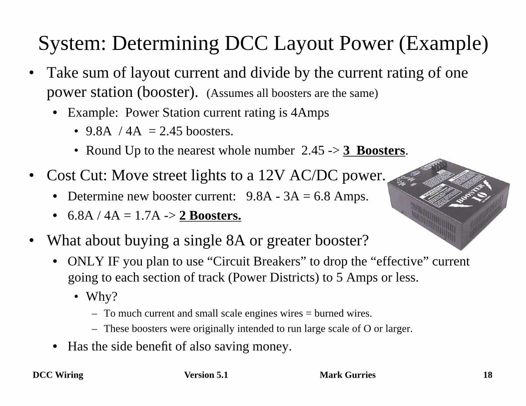
System: Determining DCC Layout Power (Example) • Take sum of layout current and divide by the current rating of one
power station (booster). (Assumes all boosters are the same) • Example: Power Station current rating is 4Amps
• 9.8A / 4A = 2.45 boosters. • Round Up to the nearest whole number 2.45 -> 3 Boosters.
• Cost Cut: Move street lights to a 12V AC/DC power. • Determine new booster current: 9.8A - 3A = 6.8 Amps. • 6.8A / 4A = 1.7A -> 2 Boosters.
• What about buying a single 8A or greater booster? • ONLY IF you plan to use “Circuit Breakers” to drop the “effective” current
going to each section of track (Power Districts) to 5 Amps or less. • Why?
– To much current and small scale engines wires = burned wires. – These boosters were originally intended to run large scale of O or larger.
• Has the side benefit of also saving money.
DCC Wiring Mark Gurries Version 5.1 19
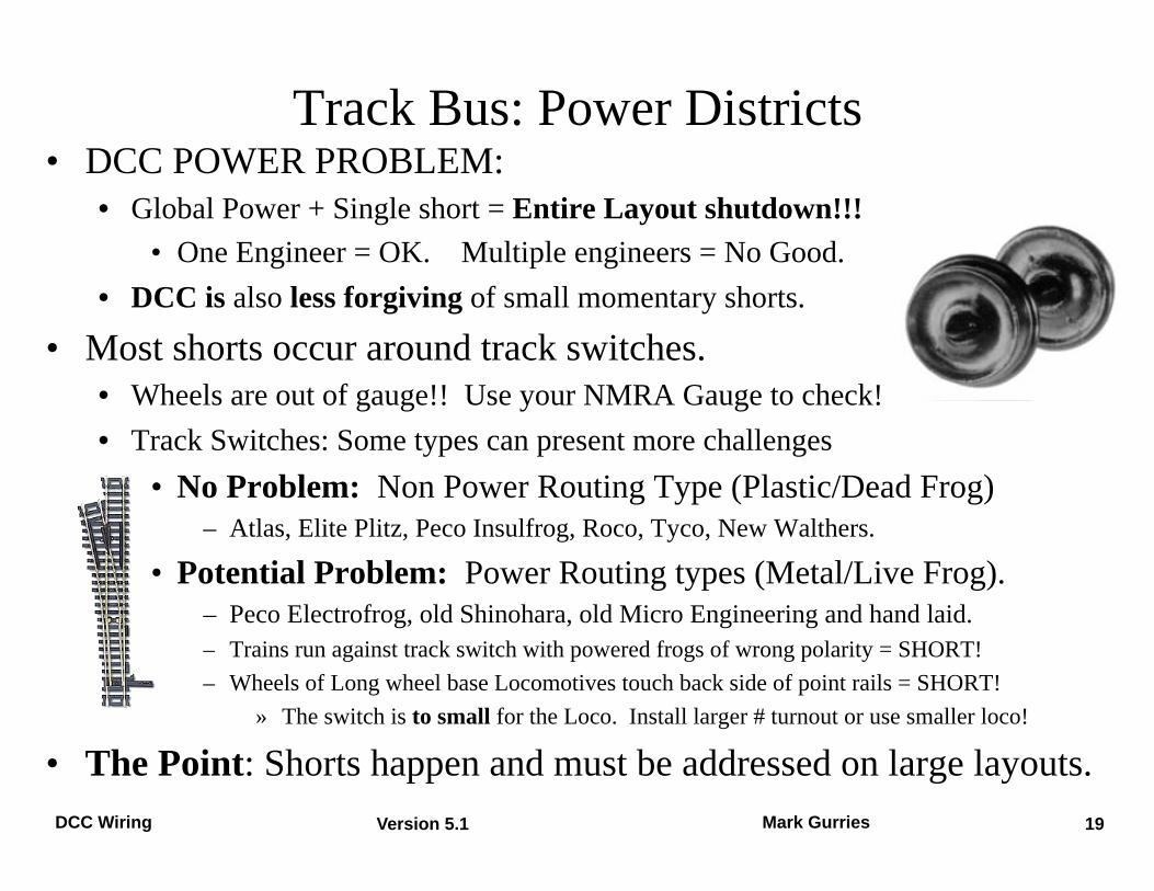
• DCC POWER PROBLEM: • Global Power + Single short = Entire Layout shutdown!!!
• One Engineer = OK. Multiple engineers = No Good. • DCC is also less forgiving of small momentary shorts.
• Most shorts occur around track switches. • Wheels are out of gauge!! Use your NMRA Gauge to check! • Track Switches: Some types can present more challenges
• No Problem: Non Power Routing Type (Plastic/Dead Frog) – Atlas, Elite Plitz, Peco Insulfrog, Roco, Tyco, New Walthers.
• Potential Problem: Power Routing types (Metal/Live Frog). – Peco Electrofrog, old Shinohara, old Micro Engineering and hand laid. – Trains run against track switch with powered frogs of wrong polarity = SHORT! – Wheels of Long wheel base Locomotives touch back side of point rails = SHORT!
» The switch is to small for the Loco. Install larger # turnout or use smaller loco!
• The Point: Shorts happen and must be addressed on large layouts.
Track Bus: Power Districts
Version 5.1 20 DCC Wiring Mark Gurries
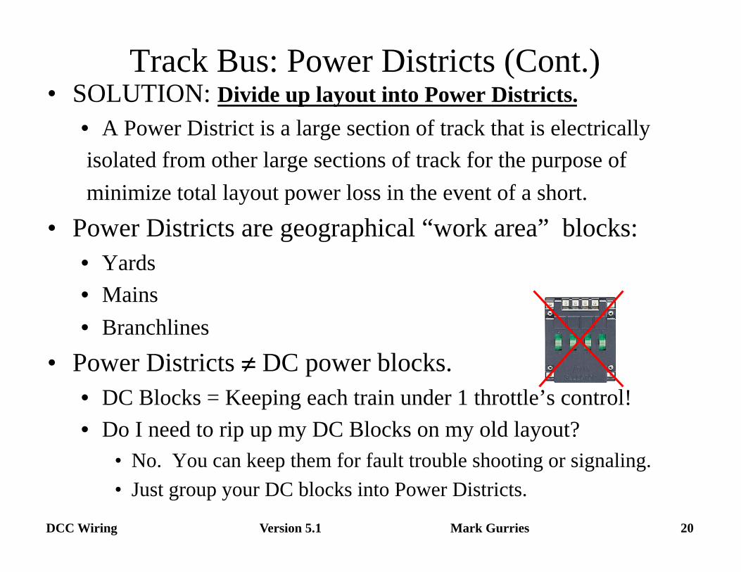
Track Bus: Power Districts (Cont.) • SOLUTION: Divide up layout into Power Districts.
• A Power District is a large section of track that is electrically isolated from other large sections of track for the purpose of minimize total layout power loss in the event of a short.
• Power Districts are geographical “work area” blocks: • Yards • Mains • Branchlines
• Power Districts ≠ DC power blocks. • DC Blocks = Keeping each train under 1 throttle’s control! • Do I need to rip up my DC Blocks on my old layout?
• No. You can keep them for fault trouble shooting or signaling. • Just group your DC blocks into Power Districts.
Version 5.1 21 DCC Wiring Mark Gurries
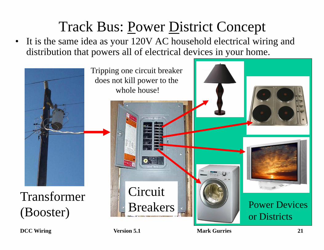
Track Bus: Power District Concept • It is the same idea as your 120V AC household electrical wiring and
distribution that powers all of electrical devices in your home.
Transformer (Booster)
Circuit Breakers Power Devices
or Districts
Tripping one circuit breaker does not kill power to the
whole house!
Version 5.1 22 DCC Wiring Mark Gurries
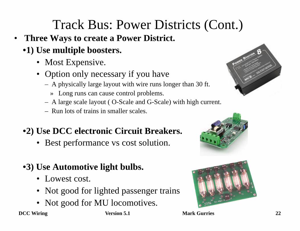
Track Bus: Power Districts (Cont.) • Three Ways to create a Power District.
• 1) Use multiple boosters. • Most Expensive. • Option only necessary if you have
– A physically large layout with wire runs longer than 30 ft. » Long runs can cause control problems.
– A large scale layout ( O-Scale and G-Scale) with high current. – Run lots of trains in smaller scales.
• 2) Use DCC electronic Circuit Breakers. • Best performance vs cost solution.
• 3) Use Automotive light bulbs. • Lowest cost. • Not good for lighted passenger trains • Not good for MU locomotives.

Version 5.1 23 DCC Wiring Mark Gurries
Track Bus: Power Districts Example Diagram
• Isolating the track power into blocks allows more trains to operate.
Single 5A booster powers 4 power districts. A short in one will not effect the others.
LARGE LAYOUT
PD = Power District
Version 5.1 24 DCC Wiring Mark Gurries
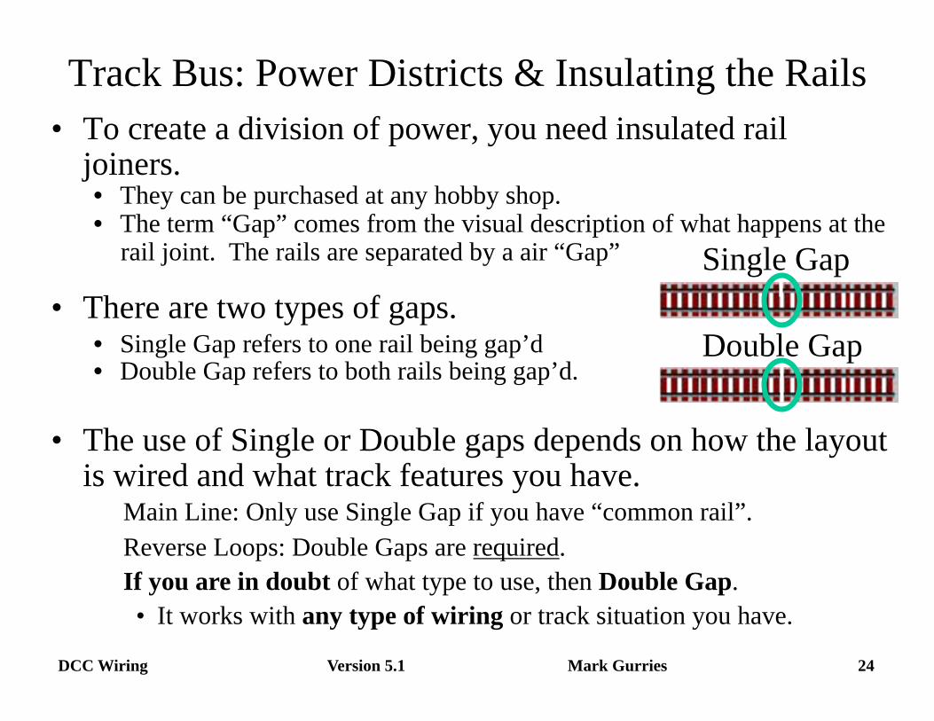
Track Bus: Power Districts & Insulating the Rails • To create a division of power, you need insulated rail
joiners. • They can be purchased at any hobby shop. • The term “Gap” comes from the visual description of what happens at the
rail joint. The rails are separated by a air “Gap”
• There are two types of gaps. • Single Gap refers to one rail being gap’d • Double Gap refers to both rails being gap’d.
Double Gap
Single Gap
• The use of Single or Double gaps depends on how the layout is wired and what track features you have. Main Line: Only use Single Gap if you have “common rail”. Reverse Loops: Double Gaps are required. If you are in doubt of what type to use, then Double Gap.
• It works with any type of wiring or track situation you have.
Version 5.1 25 DCC Wiring Mark Gurries
• Rule: When dealing with multiple boosters in individual boxes, a heavy duty wire connection is required between every booster. • This situation is found only on large layouts or large scale layouts. • This wire is above and beyond the normal control bus (booster
bus) wiring. • Why the wire at all?
• No Wire = Loco stuttering/stalling problems at power district boundary (Gaps) • Stall is GUARANTEED if loco has offset electrical wheel pickup.
• Electrical Issue: “Open Circuit” between boosters. • Each booster’s power district is a “power island” unto itself. It does
not know about it’s “next door neighbor” booster’s existence. • Wire provides electrical path to allow boosters to “see” each other
and coordinate power transfer/handoff. => No Stall.
Track Bus: Power Districts & Multiple Boosters
Version 5.1 26 DCC Wiring Mark Gurries
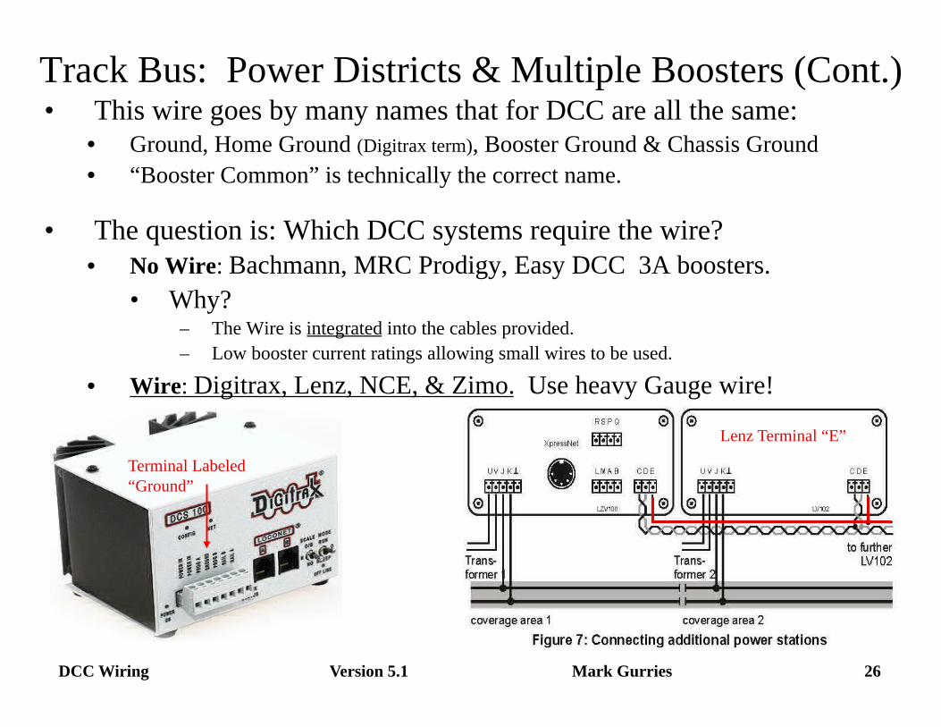
• This wire goes by many names that for DCC are all the same: • Ground, Home Ground (Digitrax term), Booster Ground & Chassis Ground • “Booster Common” is technically the correct name.
• The question is: Which DCC systems require the wire? • No Wire: Bachmann, MRC Prodigy, Easy DCC 3A boosters.
• Why? – The Wire is integrated into the cables provided. – Low booster current ratings allowing small wires to be used.
• Wire: Digitrax, Lenz, NCE, & Zimo. Use heavy Gauge wire!
Track Bus: Power Districts & Multiple Boosters (Cont.)
Terminal Labeled “Ground”
Lenz Terminal “E”
Version 5.1 27 DCC Wiring Mark Gurries
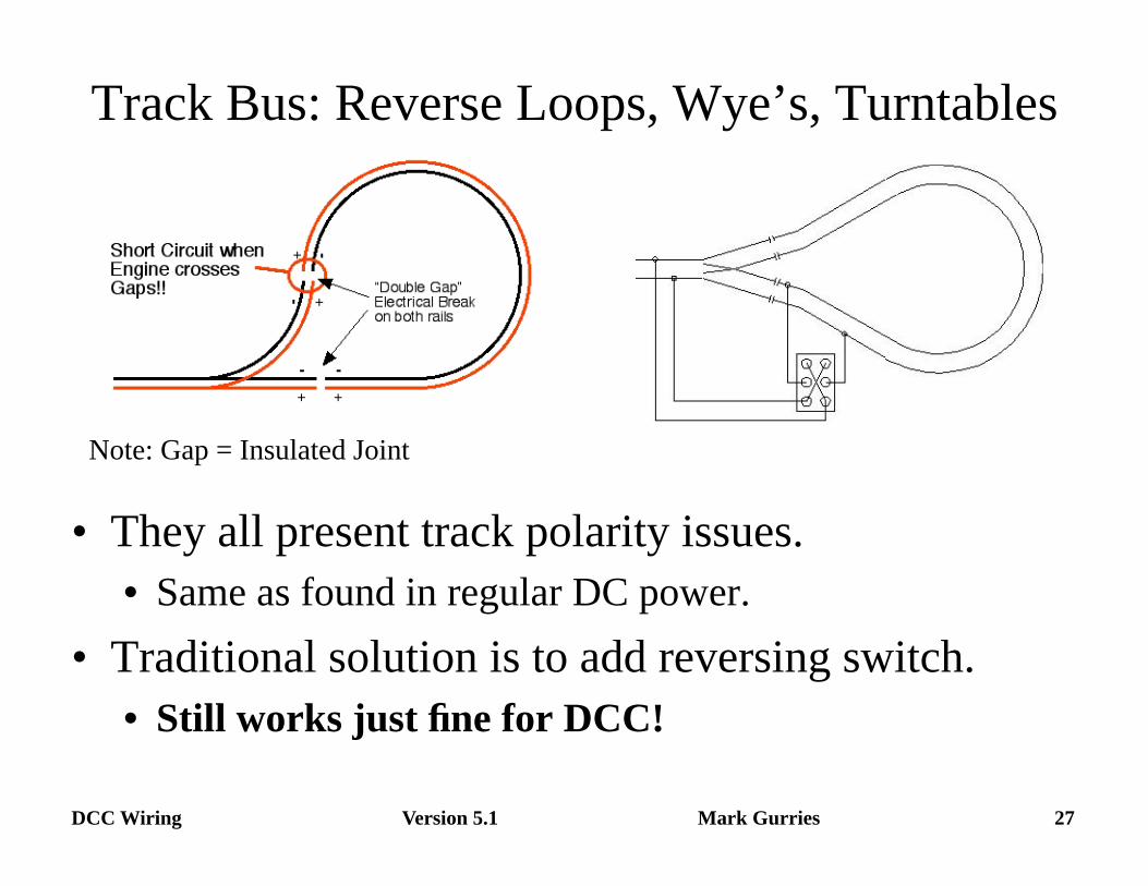
Track Bus: Reverse Loops, Wye’s, Turntables
• They all present track polarity issues. • Same as found in regular DC power.
• Traditional solution is to add reversing switch. • Still works just fine for DCC!
Note: Gap = Insulated Joint
Version 5.1 28 DCC Wiring Mark Gurries
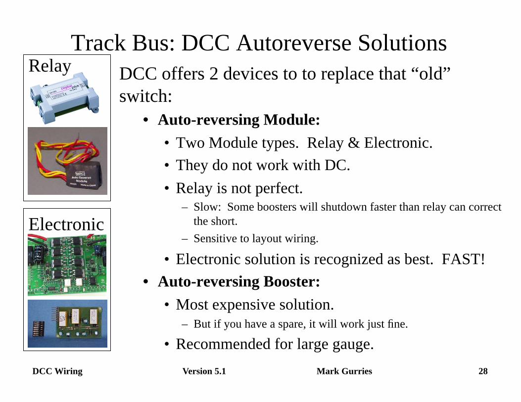
Track Bus: DCC Autoreverse Solutions DCC offers 2 devices to to replace that “old” switch:
• Auto-reversing Module: • Two Module types. Relay & Electronic. • They do not work with DC. • Relay is not perfect.
– Slow: Some boosters will shutdown faster than relay can correct the short.
– Sensitive to layout wiring.
• Electronic solution is recognized as best. FAST! • Auto-reversing Booster:
• Most expensive solution. – But if you have a spare, it will work just fine.
• Recommended for large gauge.
Relay
Electronic
Version 5.1 29 DCC Wiring Mark Gurries
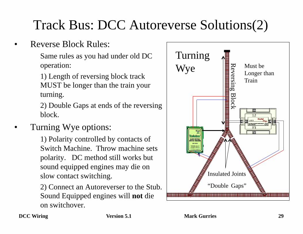
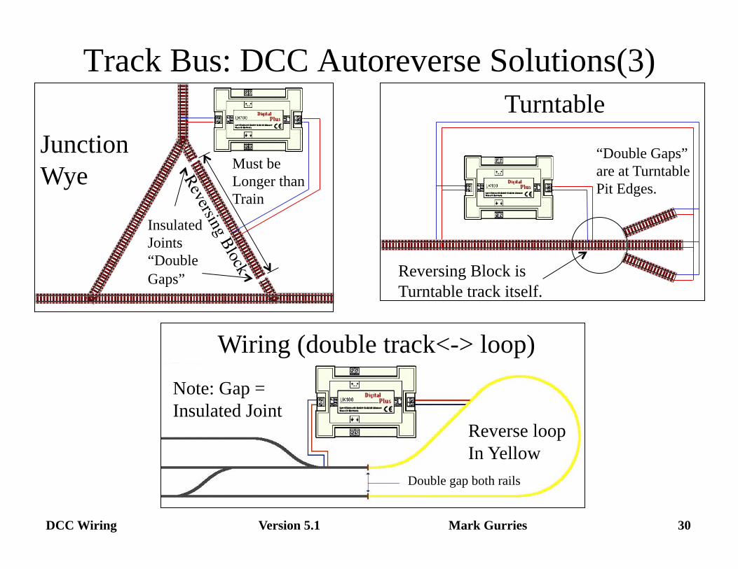
Track Bus: DCC Autoreverse Solutions(2) • Reverse Block Rules:
Same rules as you had under old DC operation: 1) Length of reversing block track MUST be longer than the train your turning. 2) Double Gaps at ends of the reversing block.
• Turning Wye options: 1) Polarity controlled by contacts of Switch Machine. Throw machine sets polarity. DC method still works but sound equipped engines may die on slow contact switching. 2) Connect an Autoreverser to the Stub. Sound Equipped engines will not die on switchover.
Insulated Joints
“Double Gaps”
Must be Longer than Train
Turning Wye
Reversing Block
Version 5.1 30 DCC Wiring Mark Gurries
Track Bus: DCC Autoreverse Solutions(3)
“Double Gaps” are at Turntable Pit Edges.
Turntable
Reversing Block is Turntable track itself.
Insulated Joints “Double Gaps”
Must be Longer than Train
Junction Wye
Wiring (double track<-> loop)
Double gap both rails
Reverse loop In Yellow
Note: Gap = Insulated Joint
Version 5.1 31 DCC Wiring Mark Gurries
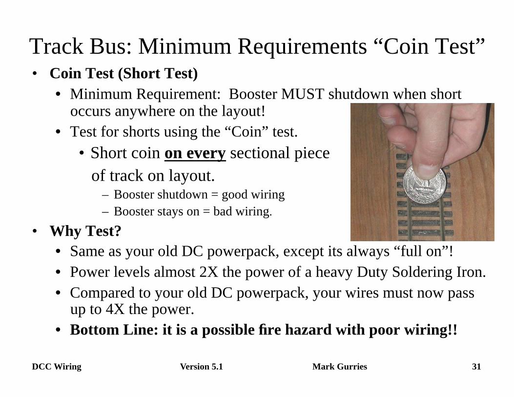
Track Bus: Minimum Requirements “Coin Test” • Coin Test (Short Test)
• Minimum Requirement: Booster MUST shutdown when short occurs anywhere on the layout!
• Test for shorts using the “Coin” test. • Short coin on every sectional piece of track on layout.
– Booster shutdown = good wiring – Booster stays on = bad wiring.
• Why Test? • Same as your old DC powerpack, except its always “full on”! • Power levels almost 2X the power of a heavy Duty Soldering Iron. • Compared to your old DC powerpack, your wires must now pass
up to 4X the power. • Bottom Line: it is a possible fire hazard with poor wiring!!
Version 5.1 32 DCC Wiring Mark Gurries
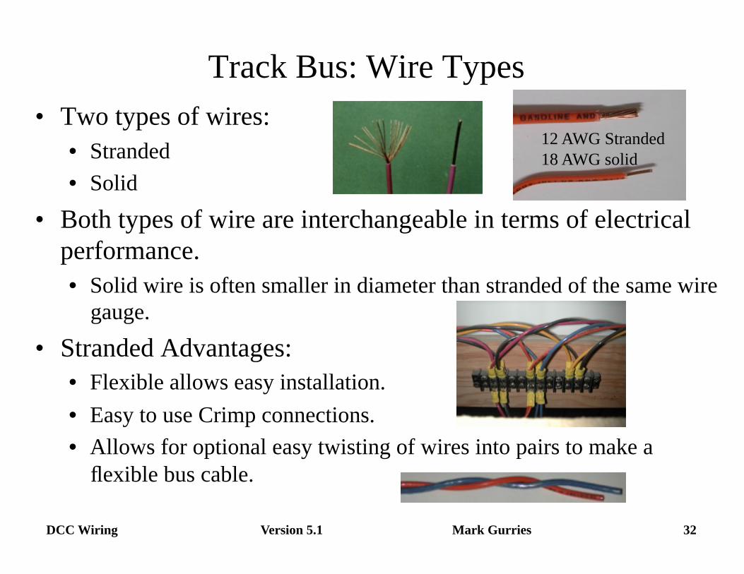
Track Bus: Wire Types • Two types of wires:
• Stranded • Solid
• Both types of wire are interchangeable in terms of electrical performance. • Solid wire is often smaller in diameter than stranded of the same wire
gauge. • Stranded Advantages:
• Flexible allows easy installation. • Easy to use Crimp connections. • Allows for optional easy twisting of wires into pairs to make a
flexible bus cable.
12 AWG Stranded 18 AWG solid
Version 5.1 33 DCC Wiring Mark Gurries
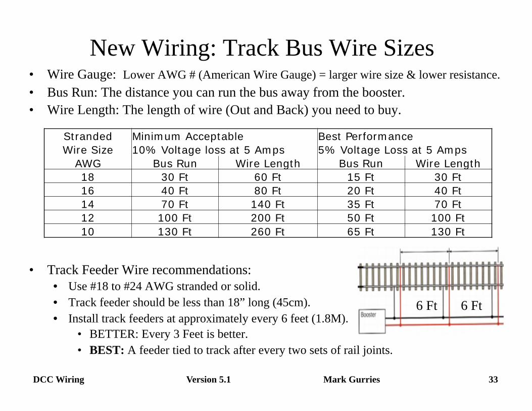
• Wire Gauge: Lower AWG # (American Wire Gauge) = larger wire size & lower resistance. • Bus Run: The distance you can run the bus away from the booster. • Wire Length: The length of wire (Out and Back) you need to buy.
• Track Feeder Wire recommendations: • Use #18 to #24 AWG stranded or solid. • Track feeder should be less than 18” long (45cm). • Install track feeders at approximately every 6 feet (1.8M).
• BETTER: Every 3 Feet is better. • BEST: A feeder tied to track after every two sets of rail joints.
New Wiring: Track Bus Wire Sizes
6 Ft 6 Ft
Stranded Minimum Acceptable Best Performance Wire Size 10% Voltage loss at 5 Amps 5% Voltage Loss at 5 Amps
AWG Bus Run Wire Length Bus Run Wire Length 18 30 Ft 60 Ft 15 Ft 30 Ft 16 40 Ft 80 Ft 20 Ft 40 Ft 14 70 Ft 140 Ft 35 Ft 70 Ft 12 100 Ft 200 Ft 50 Ft 100 Ft 10 130 Ft 260 Ft 65 Ft 130 Ft
Version 5.1 34 DCC Wiring Mark Gurries
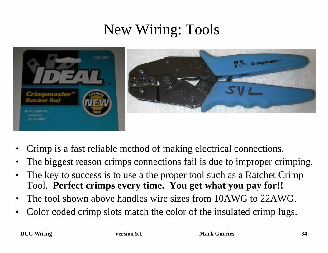
New Wiring: Tools
• Crimp is a fast reliable method of making electrical connections. • The biggest reason crimps connections fail is due to improper crimping. • The key to success is to use a the proper tool such as a Ratchet Crimp
Tool. Perfect crimps every time. You get what you pay for!! • The tool shown above handles wire sizes from 10AWG to 22AWG. • Color coded crimp slots match the color of the insulated crimp lugs.
Version 5.1 35 DCC Wiring Mark Gurries
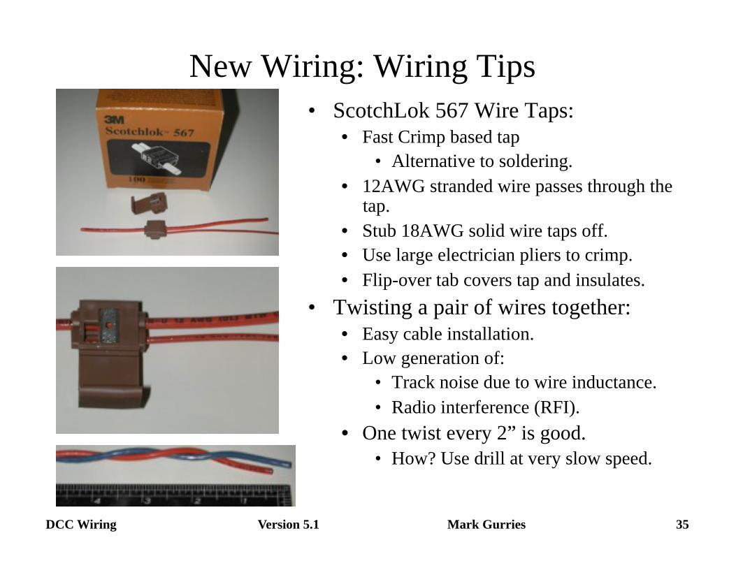
New Wiring: Wiring Tips • ScotchLok 567 Wire Taps:
• Fast Crimp based tap • Alternative to soldering.
• 12AWG stranded wire passes through the tap.
• Stub 18AWG solid wire taps off. • Use large electrician pliers to crimp. • Flip-over tab covers tap and insulates.
• Twisting a pair of wires together: • Easy cable installation. • Low generation of:
• Track noise due to wire inductance. • Radio interference (RFI).
• One twist every 2” is good. • How? Use drill at very slow speed.
Version 5.1 36 DCC Wiring Mark Gurries
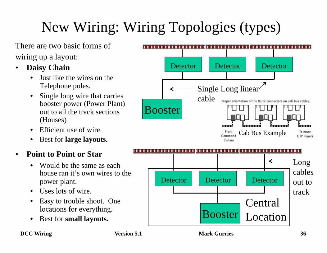
New Wiring: Wiring Topologies (types) There are two basic forms of wiring up a layout: • Daisy Chain
• Just like the wires on the Telephone poles.
• Single long wire that carries booster power (Power Plant) out to all the track sections (Houses)
• Efficient use of wire. • Best for large layouts.
• Point to Point or Star • Would be the same as each
house ran it’s own wires to the power plant.
• Uses lots of wire. • Easy to trouble shoot. One
locations for everything. • Best for small layouts.
Long cables out to track
Booster
Detector Detector Detector
Central Location
Single Long linear cable
Booster
Detector Detector Detector
Cab Bus Example
Version 5.1 37 DCC Wiring Mark Gurries
Appendix
Additional information if time permits 1) Commons 2) Multiple Booster Wiring. 3) Proposal A modular flexible layout wiring system 4) Filtering noise out of your layout wiring. 5) How to calculate Wire Voltage drops. 6) Internet Resources on DCC Wiring 7) Information about RJ telephone wiring system. 8) Revision history.
Version 5.1 38 DCC Wiring Mark Gurries
• Common: • Definition: An electrical point in a system that is shared by many
electrical devices. It’s purpose is to establish a common (shared) electrical voltage reference point so every device connected to it can work together to allow power or signals (information) to flow freely between them.
• Voltage: A common can be any voltage we want it to be. • Hot: A voltage ≠ 0V. The voltage is often use as the name. • Ground: A voltage = 0V. There is more than one type of Ground
• Examples of Commons: • A Decoders “BLUE” wire is “12V” Hot Common” for engine lights. • Planet Earth is a HUGE common called “Earth Ground” • Most Electrical devices have a Common Ground inside. • Booster Common: Used by boosters to share power between them at Power
District boundaries to coordinate smooth crossing of trains.
Wiring: Commons and DCC
Version 5.1 39 DCC Wiring Mark Gurries
• There are 3 types of commons possible in DCC for track power: • Common Rail (Used on large DC layouts to save wire.) • Booster Common (DCC preferred) • Power Supply Common. (Shared Power supply)
• Not recommended with DCC. Potential Hazards, • Which one to use?
• Do you even know what Common Rail is? • YES: Use boosters design for Common Rail.
– Use “Optical Isolated” Control/Booster Bus inputs
• NO: Then you do not need to know. Use Booster Common. – Follow Booster’s Instructions for connecting multiple boosters,
• Only ONE type of common is allowed. • Pick one and stick with it! • Using both together can cause problems or even damage.
Wiring: Commons and DCC (Cont.)
Version 5.1 40 DCC Wiring Mark Gurries
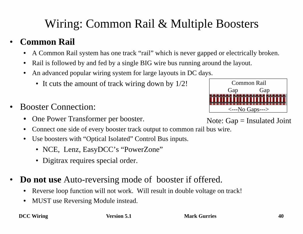
• Common Rail • A Common Rail system has one track “rail” which is never gapped or electrically broken. • Rail is followed by and fed by a single BIG wire bus running around the layout. • An advanced popular wiring system for large layouts in DC days.
• It cuts the amount of track wiring down by 1/2!
• Booster Connection: • One Power Transformer per booster. • Connect one side of every booster track output to common rail bus wire. • Use boosters with “Optical Isolated” Control Bus inputs.
• NCE, Lenz, EasyDCC’s “PowerZone” • Digitrax requires special order.
• Do not use Auto-reversing mode of booster if offered. • Reverse loop function will not work. Will result in double voltage on track! • MUST use Reversing Module instead.
Wiring: Common Rail & Multiple Boosters
Common Rail Gap Gap
<---No Gaps---> Note: Gap = Insulated Joint
Version 5.1 41 DCC Wiring Mark Gurries
• Booster Common or “Home Ground”. • Common developed inside the booster/power station.
• Booster Connections: • One Power Supply per Booster. • Install Booster Common per Manufacture instructions.
• Some boosters have a dedicated terminals to do this. • Some boosters simply need their metal chassis (case) connected together. • Some boosters have integrated it into provided cables to make this
connection. • Connect outputs directly to tracks within this booster Power district,.
• Advantages: • Recommended by all DCC manufactures. • Compatible with all boosters made today. • Compatible with Auto Reversing boosters. • Easily supports the traditional “Point to Point” layout wiring system.
• Disadvantages: Does not reduce track wiring.
Wiring: Booster Common & Multiple Boosters
Version 5.1 42 DCC Wiring Mark Gurries
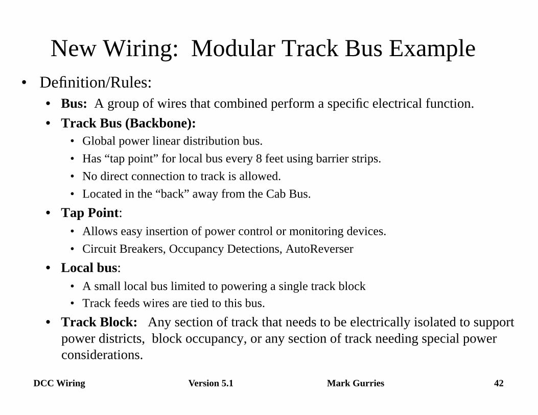
New Wiring: Modular Track Bus Example • Definition/Rules:
• Bus: A group of wires that combined perform a specific electrical function. • Track Bus (Backbone):
• Global power linear distribution bus. • Has “tap point” for local bus every 8 feet using barrier strips. • No direct connection to track is allowed. • Located in the “back” away from the Cab Bus.
• Tap Point: • Allows easy insertion of power control or monitoring devices. • Circuit Breakers, Occupancy Detections, AutoReverser
• Local bus: • A small local bus limited to powering a single track block • Track feeds wires are tied to this bus.
• Track Block: Any section of track that needs to be electrically isolated to support power districts, block occupancy, or any section of track needing special power considerations.
Version 5.1 43 DCC Wiring Mark Gurries
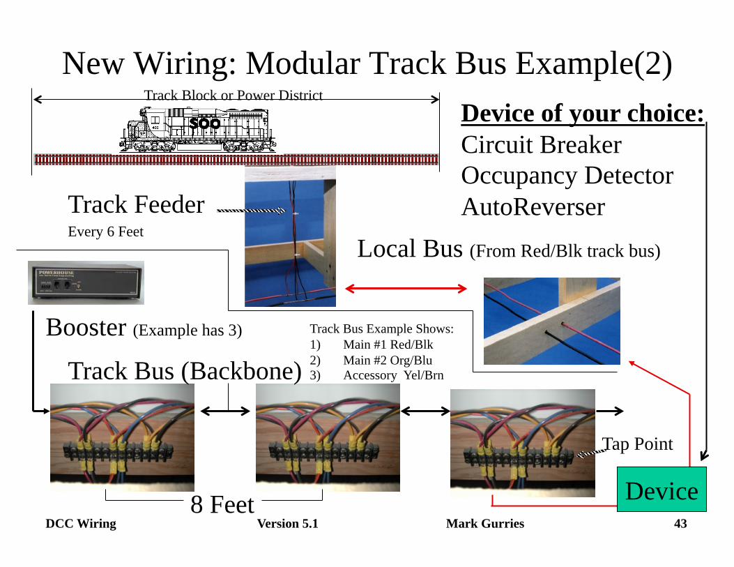
New Wiring: Modular Track Bus Example(2)
Local Bus (From Red/Blk track bus)
Track Bus (Backbone)
Tap Point
Booster (Example has 3)
8 Feet
Track Feeder Every 6 Feet
Device
Device of your choice: Circuit Breaker Occupancy Detector AutoReverser
Track Bus Example Shows: 1) Main #1 Red/Blk 2) Main #2 Org/Blu 3) Accessory Yel/Brn
Track Block or Power District
Version 5.1 44 DCC Wiring Mark Gurries
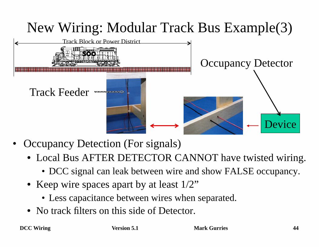
New Wiring: Modular Track Bus Example(3)
Track Feeder
Device
Occupancy Detector
Track Block or Power District
• Occupancy Detection (For signals) • Local Bus AFTER DETECTOR CANNOT have twisted wiring.
• DCC signal can leak between wire and show FALSE occupancy. • Keep wire spaces apart by at least 1/2”
• Less capacitance between wires when separated. • No track filters on this side of Detector.
Version 5.1 45 DCC Wiring Mark Gurries
Noise Filtering Of Track Power • Decoders must have clean strong signal for reliable operation. • Decoders can become confused and do bad things if:
• Distortion/noise of DCC signal prevents acceptance of commands. • Loss of full control.
– No control: Unresponsive to commands depending on location on layout. – Partial Control: Engine works in one direction on the track but does not work at all
going the other way,.
• Momentary Shorts on the track create Voltage spikes. • Sudden high current flow + natural inductance of wires
creates ADDITIONAL voltage. – Electrical Law: V = L x ∆I/∆t where:
» L = Inductance of wires, ∆I = Change in current., ∆t= Change in time. – L is a property of wires. Think coil and motors and switch arcing (spark!) when
turned off.
• If voltage is strong enough, it can: – Cause the decoder to forget it settings and require reprogramming. – Literally blow up and die do to electrical overstress of the electronics.
Version 5.1 46 DCC Wiring Mark Gurries
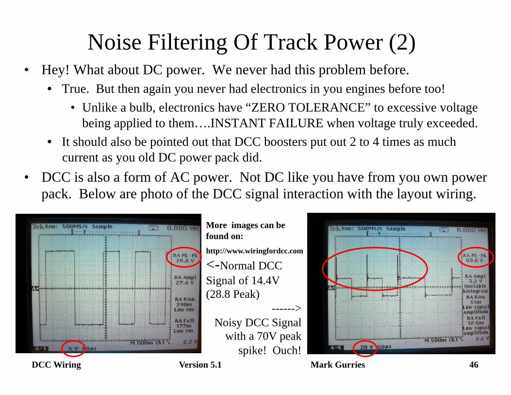
Noise Filtering Of Track Power (2) • Hey! What about DC power. We never had this problem before.
• True. But then again you never had electronics in you engines before too! • Unlike a bulb, electronics have “ZERO TOLERANCE” to excessive voltage
being applied to them….INSTANT FAILURE when voltage truly exceeded. • It should also be pointed out that DCC boosters put out 2 to 4 times as much
current as you old DC power pack did. • DCC is also a form of AC power. Not DC like you have from you own power
pack. Below are photo of the DCC signal interaction with the layout wiring.
More images can be found on: http://www.wiringfordcc.com
<-Normal DCC Signal of 14.4V (28.8 Peak)
------> Noisy DCC Signal
with a 70V peak spike! Ouch!
Version 5.1 47 DCC Wiring Mark Gurries
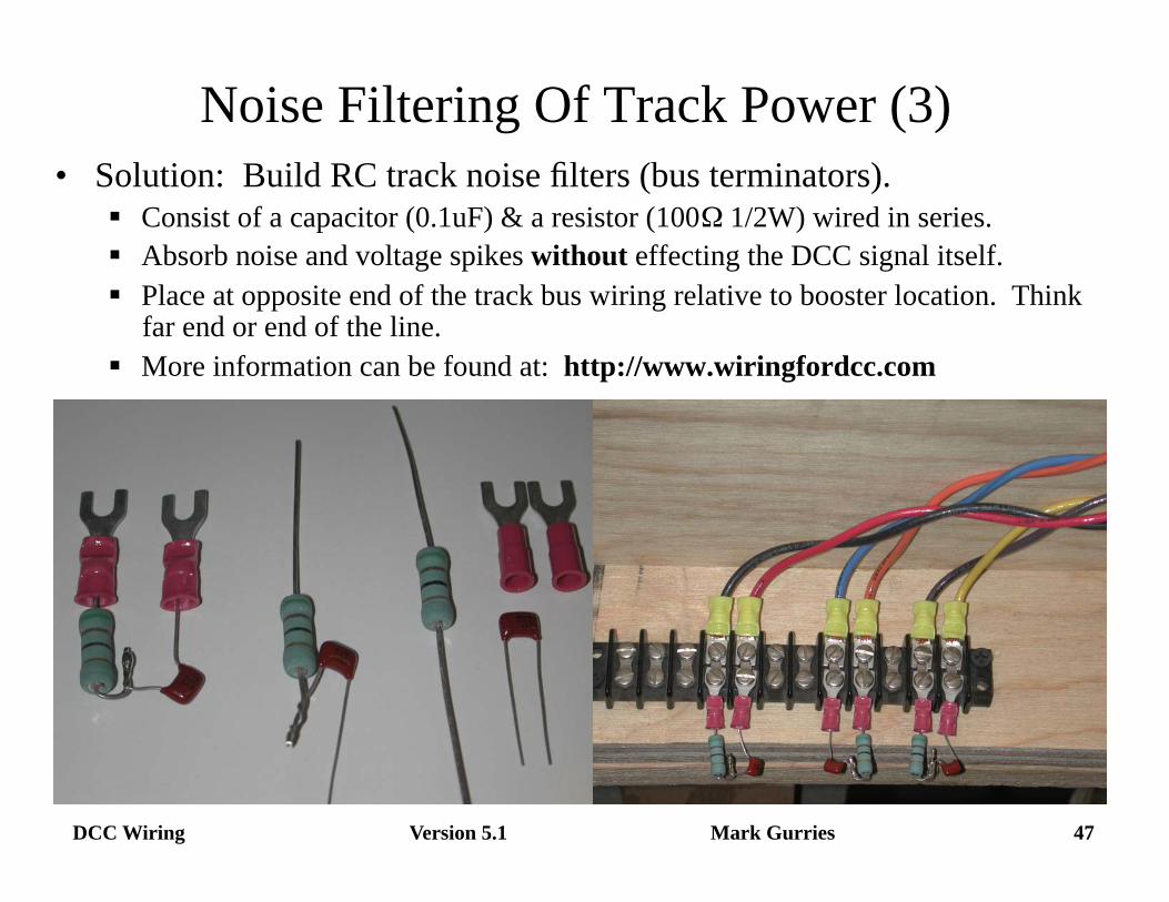
Noise Filtering Of Track Power (3) • Solution: Build RC track noise filters (bus terminators).
Consist of a capacitor (0.1uF) & a resistor (100Ω 1/2W) wired in series. Absorb noise and voltage spikes without effecting the DCC signal itself. Place at opposite end of the track bus wiring relative to booster location. Think
far end or end of the line. More information can be found at: http://www.wiringfordcc.com
Version 5.1 48 DCC Wiring Mark Gurries
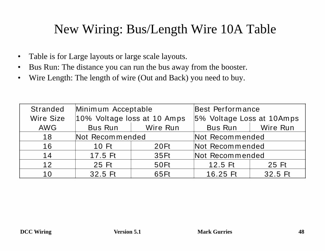
• Table is for Large layouts or large scale layouts. • Bus Run: The distance you can run the bus away from the booster. • Wire Length: The length of wire (Out and Back) you need to buy.
New Wiring: Bus/Length Wire 10A Table
Stranded Minimum Acceptable Best Performance Wire Size 10% Voltage loss at 10 Amps 5% Voltage Loss at 10Amps
AWG Bus Run Wire Run Bus Run Wire Run 18 Not Recommended Not Recommended 16 10 Ft 20Ft Not Recommended 14 17.5 Ft 35Ft Not Recommended 12 25 Ft 50Ft 12.5 Ft 25 Ft 10 32.5 Ft 65Ft 16.25 Ft 32.5 Ft
Version 5.1 49 DCC Wiring Mark Gurries
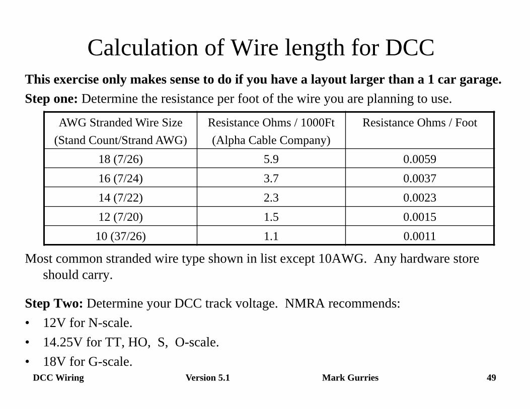
Calculation of Wire length for DCC This exercise only makes sense to do if you have a layout larger than a 1 car garage. Step one: Determine the resistance per foot of the wire you are planning to use.
Most common stranded wire type shown in list except 10AWG. Any hardware store should carry.
Step Two: Determine your DCC track voltage. NMRA recommends: • 12V for N-scale. • 14.25V for TT, HO, S, O-scale. • 18V for G-scale.
AWG Stranded Wire Size (Stand Count/Strand AWG)
Resistance Ohms / 1000Ft (Alpha Cable Company)
Resistance Ohms / Foot
18 (7/26) 5.9 0.0059 16 (7/24) 3.7 0.0037 14 (7/22) 2.3 0.0023 12 (7/20) 1.5 0.0015 10 (37/26) 1.1 0.0011
Version 5.1 50 DCC Wiring Mark Gurries
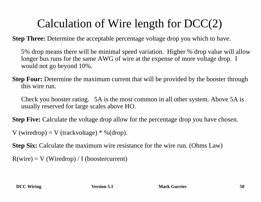
Calculation of Wire length for DCC(2) Step Three: Determine the acceptable percentage voltage drop you which to have.
5% drop means there will be minimal speed variation. Higher % drop value will allow longer bus runs for the same AWG of wire at the expense of more voltage drop. I would not go beyond 10%.
Step Four: Determine the maximum current that will be provided by the booster through this wire run.
Check you booster rating. 5A is the most common in all other system. Above 5A is usually reserved for large scales above HO.
Step Five: Calculate the voltage drop allow for the percentage drop you have chosen.
V (wiredrop) = V (trackvoltage) * %(drop).
Step Six: Calculate the maximum wire resistance for the wire run. (Ohms Law)
R(wire) = V (Wiredrop) / I (boostercurrent)
Version 5.1 51 DCC Wiring Mark Gurries
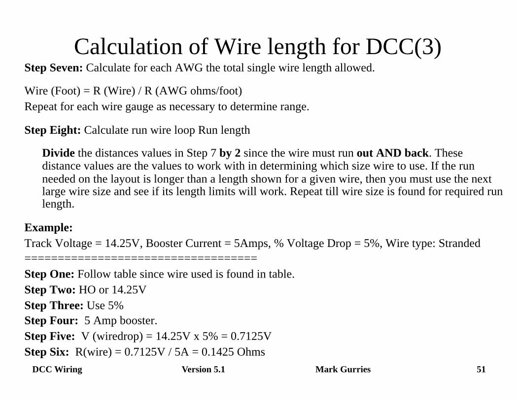
Calculation of Wire length for DCC(3) Step Seven: Calculate for each AWG the total single wire length allowed.
Wire (Foot) = R (Wire) / R (AWG ohms/foot) Repeat for each wire gauge as necessary to determine range.
Step Eight: Calculate run wire loop Run length
Divide the distances values in Step 7 by 2 since the wire must run out AND back. These distance values are the values to work with in determining which size wire to use. If the run needed on the layout is longer than a length shown for a given wire, then you must use the next large wire size and see if its length limits will work. Repeat till wire size is found for required run length.
Example: Track Voltage = 14.25V, Booster Current = 5Amps, % Voltage Drop = 5%, Wire type: Stranded =================================== Step One: Follow table since wire used is found in table. Step Two: HO or 14.25V Step Three: Use 5% Step Four: 5 Amp booster. Step Five: V (wiredrop) = 14.25V x 5% = 0.7125V Step Six: R(wire) = 0.7125V / 5A = 0.1425 Ohms
Version 5.1 52 DCC Wiring Mark Gurries
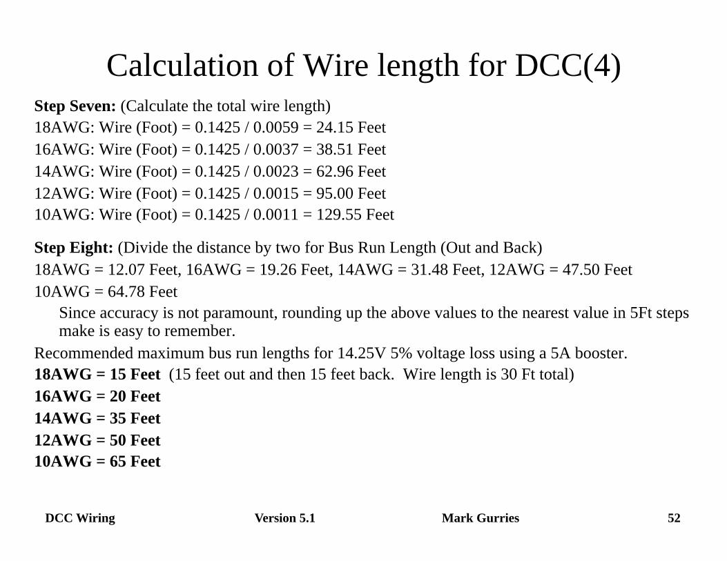
Calculation of Wire length for DCC(4) Step Seven: (Calculate the total wire length) 18AWG: Wire (Foot) = 0.1425 / 0.0059 = 24.15 Feet 16AWG: Wire (Foot) = 0.1425 / 0.0037 = 38.51 Feet 14AWG: Wire (Foot) = 0.1425 / 0.0023 = 62.96 Feet 12AWG: Wire (Foot) = 0.1425 / 0.0015 = 95.00 Feet 10AWG: Wire (Foot) = 0.1425 / 0.0011 = 129.55 Feet
Step Eight: (Divide the distance by two for Bus Run Length (Out and Back) 18AWG = 12.07 Feet, 16AWG = 19.26 Feet, 14AWG = 31.48 Feet, 12AWG = 47.50 Feet 10AWG = 64.78 Feet Since accuracy is not paramount, rounding up the above values to the nearest value in 5Ft steps make is easy to remember.
Recommended maximum bus run lengths for 14.25V 5% voltage loss using a 5A booster. 18AWG = 15 Feet (15 feet out and then 15 feet back. Wire length is 30 Ft total) 16AWG = 20 Feet 14AWG = 35 Feet 12AWG = 50 Feet 10AWG = 65 Feet
Version 5.1 53 DCC Wiring Mark Gurries
DCC Wiring related Websites • How to wire layout for best DCC operation
• General: • http://www.wiringfordcc.com
• Grounding and Common Rail issues • http://www.rr-cirkits.com/commons.html • http://www.tttrains.com/dcc/commonrail.html • http://home.neo.rr.com/mrwithdcc/hints.html#commons • http://www.siliconvalleylines.org/dcc/presentations.html DCC Boosters, Grounds & Commons
Version 5.1 54 DCC Wiring Mark Gurries
What with this RJ stuff? • RJ stands for Registered Jack under FCC Part 68 Telephony rules. • The connectors and jack we use today are part of the MODULAR phone connection
system developed by AMP corporation. They are not part of the FCC rules. • RJxx describes a type of FCC service connection. (See FCC rules part 68)
• It does NOT define a specific connector. However, the industry uses Modular. • It does define the number of wires and the pin number location. • It does NOT allow for wire reversals. All connections are pin to pin.
• The telephone industry use #p#c definition for cable connection. • #p = Max # of possible connections. #c = Actual # of wires connected. • Example:
• RJ11 is a single phone service. It is a 6p2c connection with Pin3=Tip, Pin4= Ring. • RJ14 is a dual phone service. It is a 6p4c connection with pins 2R ,3T,4R, & 5T used.
• Some RJ numbers are made up and not FCC registered. • RJ12 appears to be a network industry definition for 6p6c Data Connection. • RJH or Headset Jack appears to be a practical description of 4p4c connection.
• There is a lot of BAD information out there & the industry pushes it not knowing. • Since phones work with wire reversed cables, there is no effort to do pin to pin.
DCC Wiring Mark Gurries Version 5.1 55
Convention Revision History • V 1.0 PCR mini 9/13/98 • V 1.0 NMRA 2000 (Updated PCR) • V 2.0 PCR & NMRA 2003 • V 3.0 PCR 2006 • V 4.0 NMRA 2007 • V 5.0 NMRA 2008 • V 5.1 PCR 2009