
DCC Electronics Survey. .
28
DCC Electronics Survey
-
date post
22-Dec-2015 -
Category
Documents
-
view
228 -
download
0
Transcript of DCC Electronics Survey. .

DCC ElectronicsSurvey
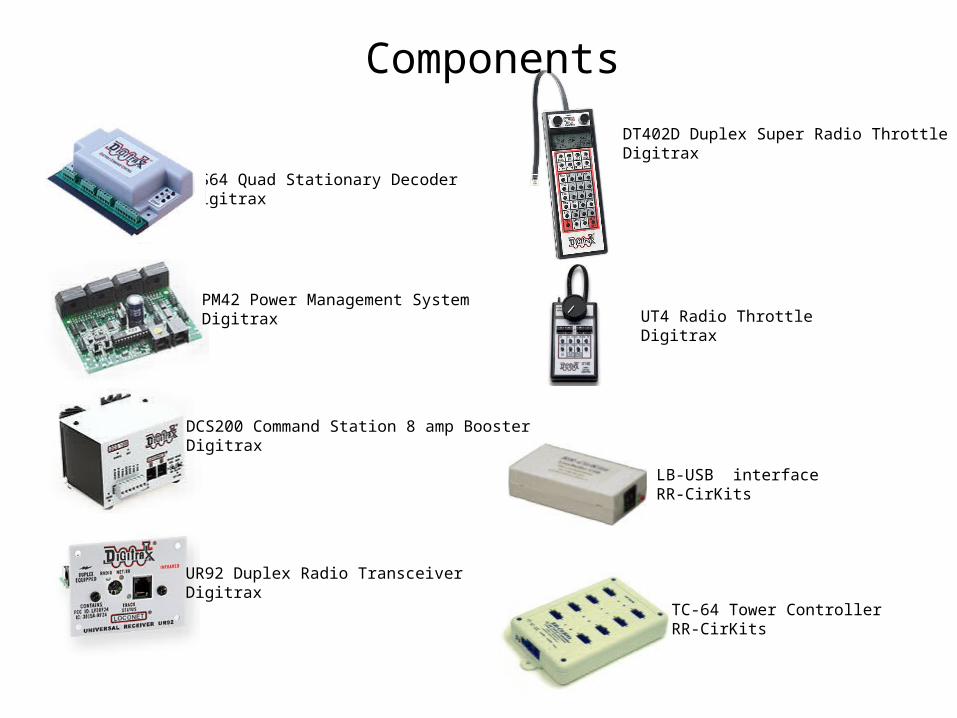
DS64 Quad Stationary DecoderDigitrax
PM42 Power Management SystemDigitrax
DCS200 Command Station 8 amp BoosterDigitrax
UR92 Duplex Radio TransceiverDigitrax
DT402D Duplex Super Radio ThrottleDigitrax
Components
LB-USB interfaceRR-CirKits
TC-64 Tower ControllerRR-CirKits
UT4 Radio ThrottleDigitrax
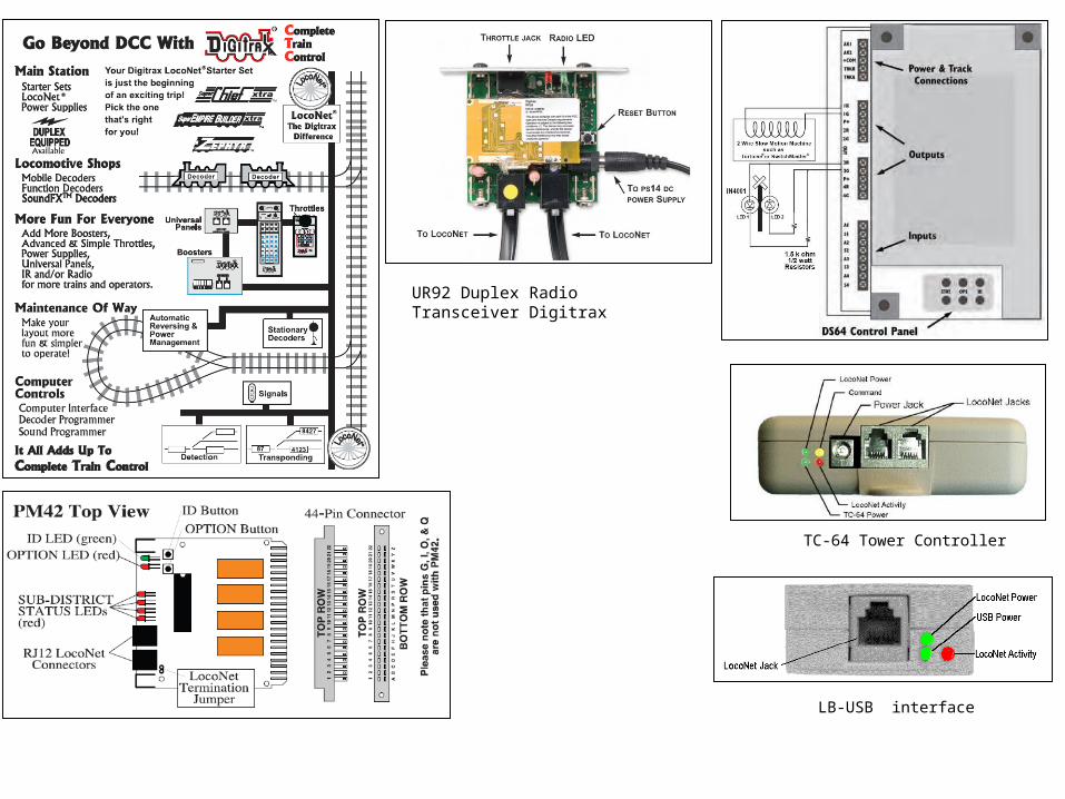
UR92 Duplex Radio Transceiver Digitrax
TC-64 Tower Controller
LB-USB interface
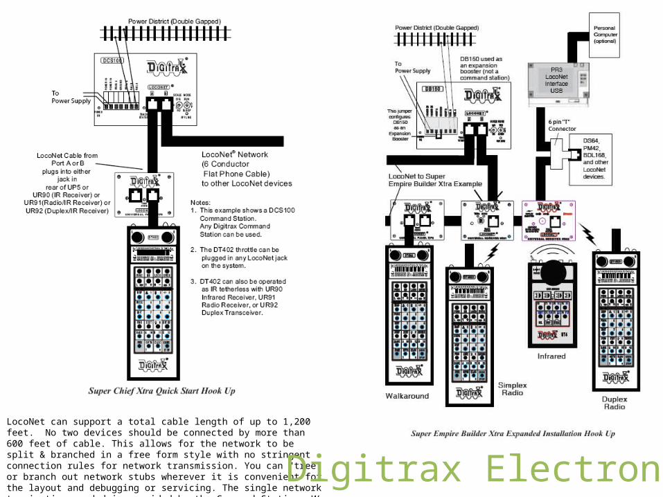
LocoNet can support a total cable length of up to 1,200 feet. No two devices should be connected by more than 600 feet of cable. This allows for the network to be split & branched in a free form style with no stringent connection rules for network transmission. You can "tree" or branch out network stubs wherever it is convenient for the layout and debugging or servicing. The single network termination needed is provided by the Command Station. We do not recommend looping the network back on itself.
Digitrax Electronics
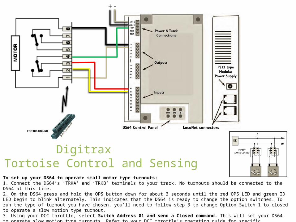
To set up your DS64 to operate stall motor type turnouts:1. Connect the DS64’s ‘TRKA’ and ‘TRKB’ terminals to your track. No turnouts should be connected to the DS64 at this time.2. On the DS64 press and hold the OPS button down for about 3 seconds until the red OPS LED and green ID LED begin to blink alternately. This indicates that the DS64 is ready to change the option switches. To run the type of turnout you have chosen, you’ll need to follow step 3 to change Option Switch 1 to closed to operate a slow motion type turnout.3. Using your DCC throttle, select Switch Address 01 and send a Closed command. This will set your DS64 to operate slow motion type turnouts. Refer to your DCC throttle’s operating guide for specific instructions for selecting switch addresses and sending switch commands.4. Exit the set up mode by again pressing and holding the OPS button on the DS64 until the red LED stops blinking.
DigitraxDS64 Tortoise Control and Sensing
EDC306100-ND
-+
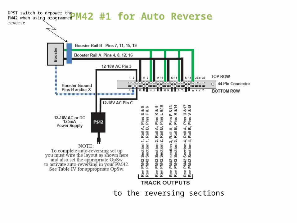
PM42 #1 for Auto Reverse
to the reversing sections
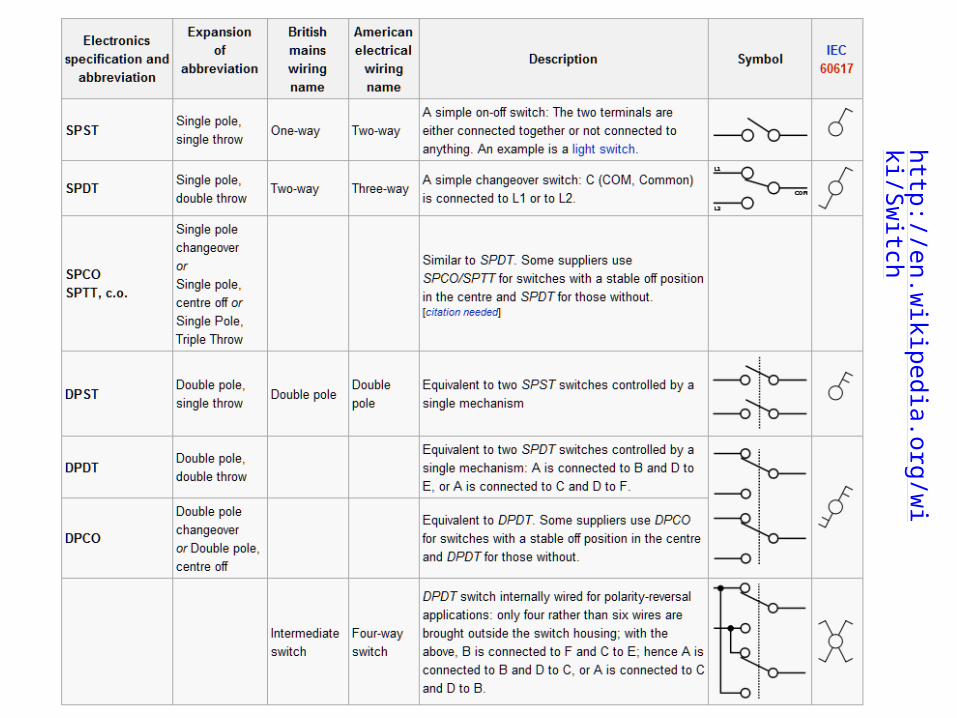
DPST switch to depower the PM42 when using programmed reverse
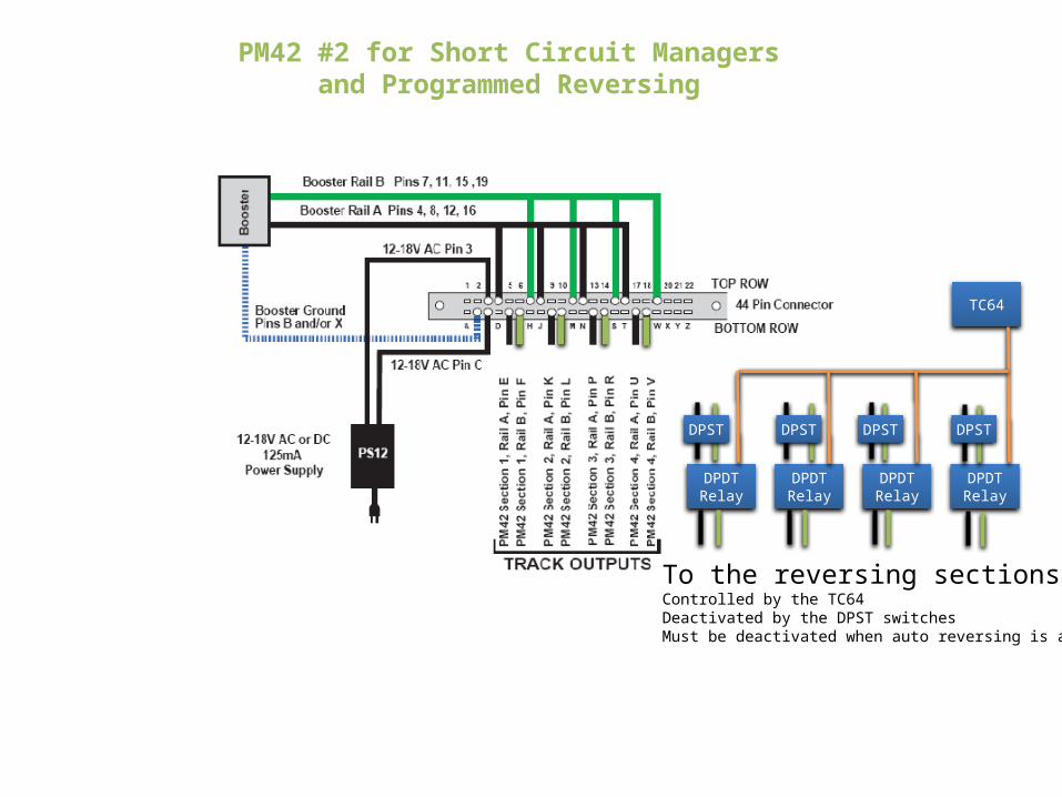
PM42 #2 for Short Circuit Managersand Programmed Reversing
DPDTRelay
DPDTRelay
DPDTRelay
DPDTRelay
To the reversing sectionsControlled by the TC64Deactivated by the DPST switchesMust be deactivated when auto reversing is active
TC64
DPST DPST DPST DPST
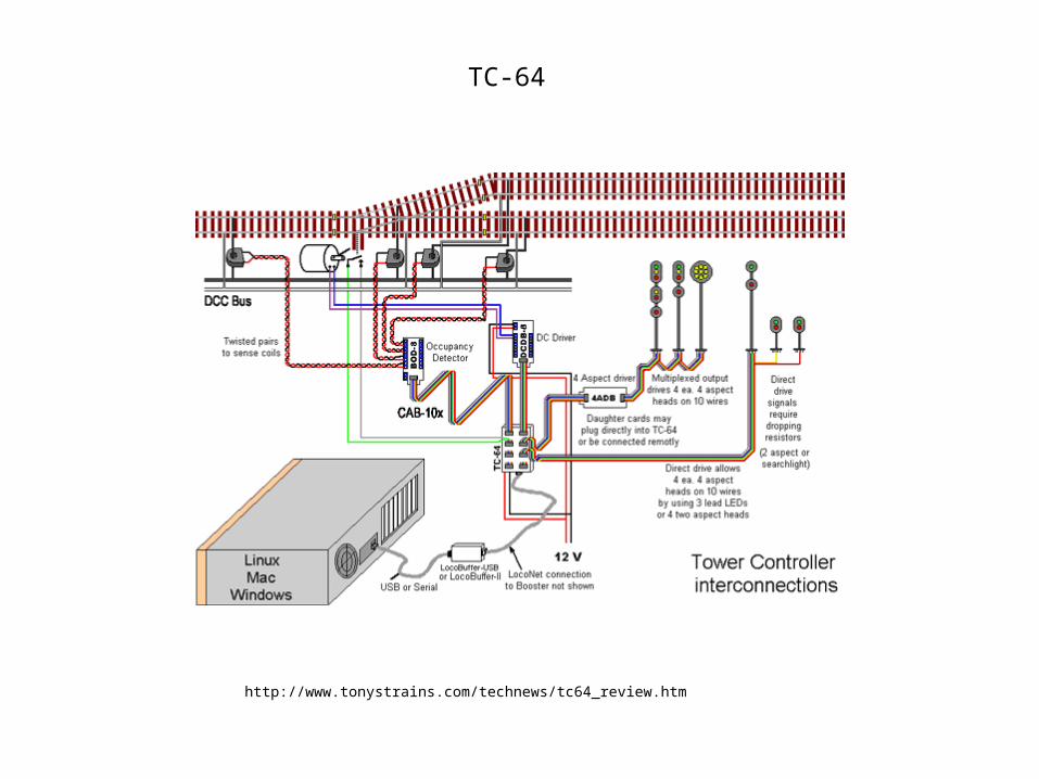
http://www.tonystrains.com/technews/tc64_review.htm
TC-64
SensorSensorSensorSensorSensorSensorSensorSensor
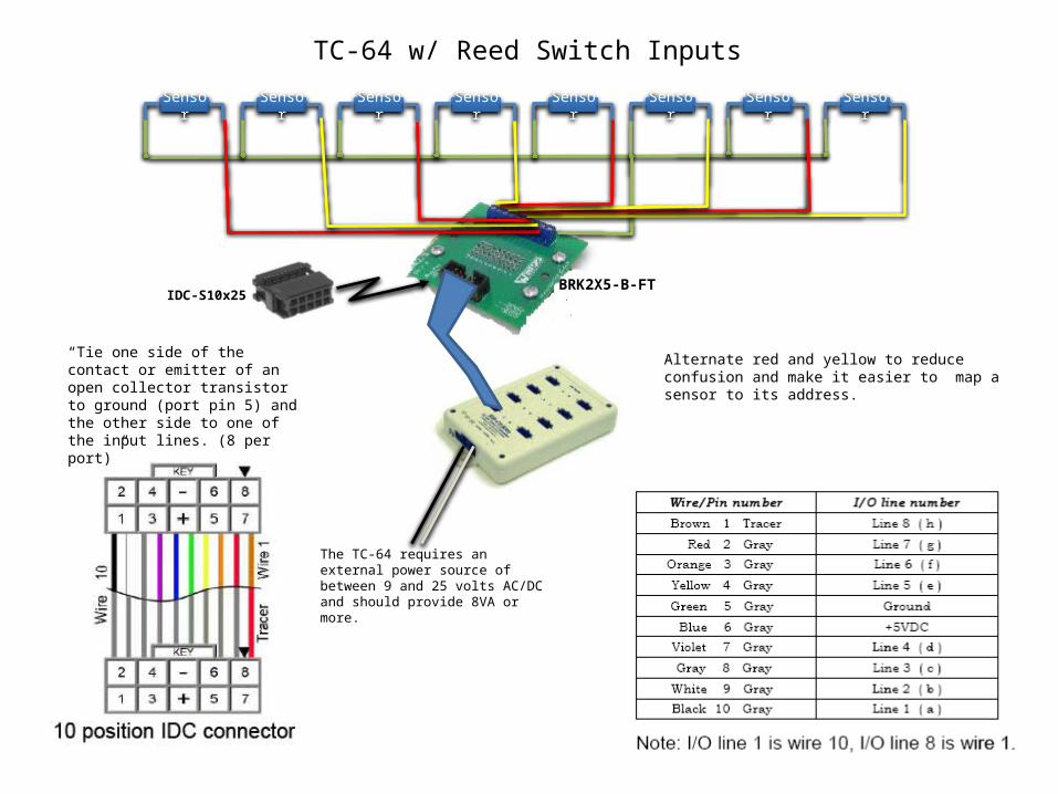
TC-64 w/ Reed Switch Inputs
“Tie one side of the contact or emitter of an open collector transistor to ground (port pin 5) and the other side to one of the input lines. (8 per port)”
Alternate red and yellow to reduce confusion and make it easier to map a sensor to its address.
BRK2X5-B-FTIDC-S10x25
The TC-64 requires an external power source of between 9 and 25 volts AC/DC and should provide 8VA or more.
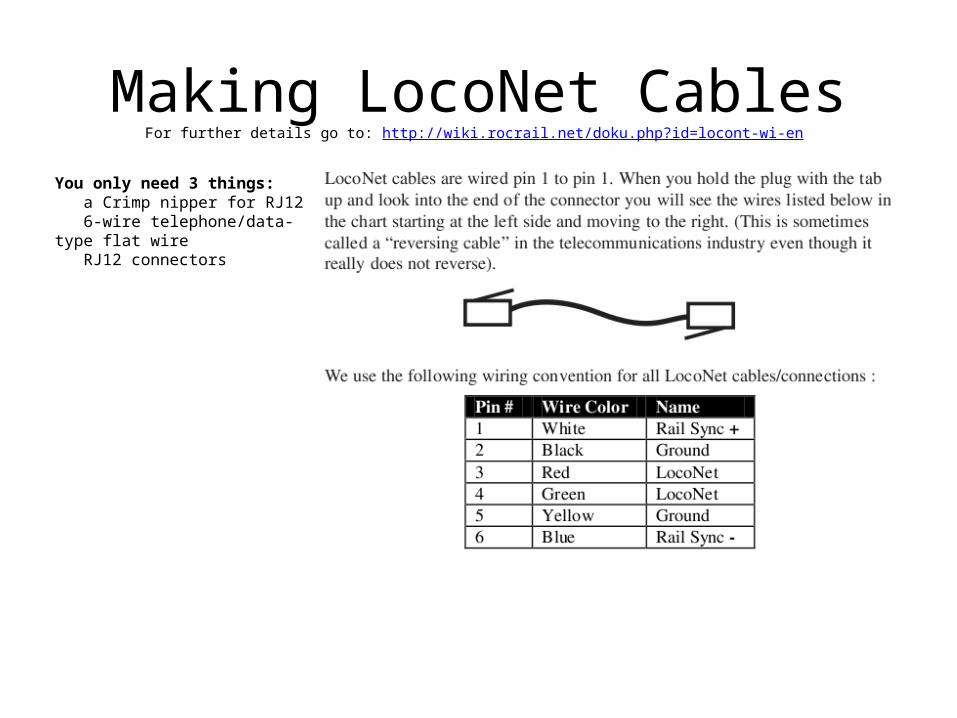
Making LocoNet CablesFor further details go to: http://wiki.rocrail.net/doku.php?id=locont-wi-en
You only need 3 things: a Crimp nipper for RJ12 6-wire telephone/data-type flat wire RJ12 connectors

Benchwork and
Roadbed
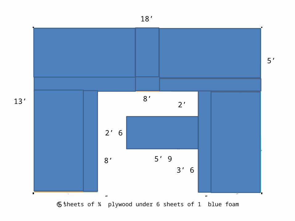
18’
5’
13’
3’ 6”
2’
2’ 6”
5’ 9”8’
8’
5’
6 sheets of ¾” plywood under 6 sheets of 1” blue foam
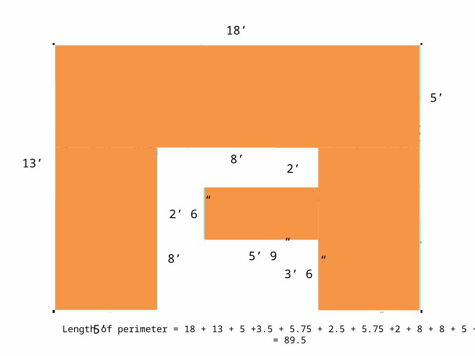
18’
5’
13’
3’ 6”
2’
2’ 6”
5’ 9”8’
8’
5’
Length of perimeter = 18 + 13 + 5 +3.5 + 5.75 + 2.5 + 5.75 +2 + 8 + 8 + 5 + 13 = 89.5
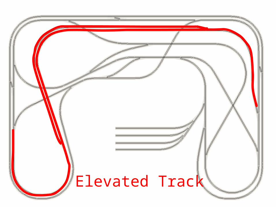
Elevated Track
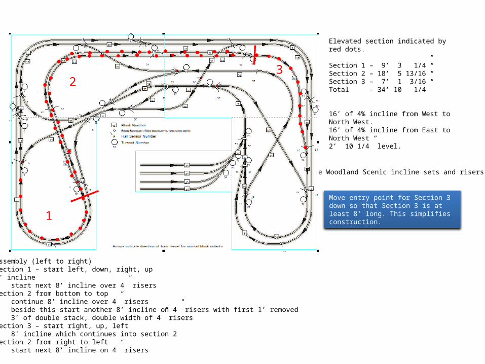
Elevated section indicated by red dots.
Section 1 – 9’ 3 1/4”Section 2 – 18’ 5 13/16”Section 3 – 7’ 1 3/16”Total – 34’ 10 1/4”
16’ of 4% incline from West to North West.16’ of 4% incline from East to North West2’ 10 1/4” level.
Use Woodland Scenic incline sets and risers
Assembly (left to right)Section 1 – start left, down, right, up8’ incline start next 8’ incline over 4” risersSection 2 from bottom to top continue 8’ incline over 4” risers beside this start another 8’ incline on 4” risers with first 1’ removed 3’ of double stack, double width of 4” risersSection 3 – start right, up, left 8’ incline which continues into section 2Section 2 from right to left start next 8’ incline on 4” risers
1
23
Move entry point for Section 3 down so that Section 3 is at least 8’ long. This simplifies construction.
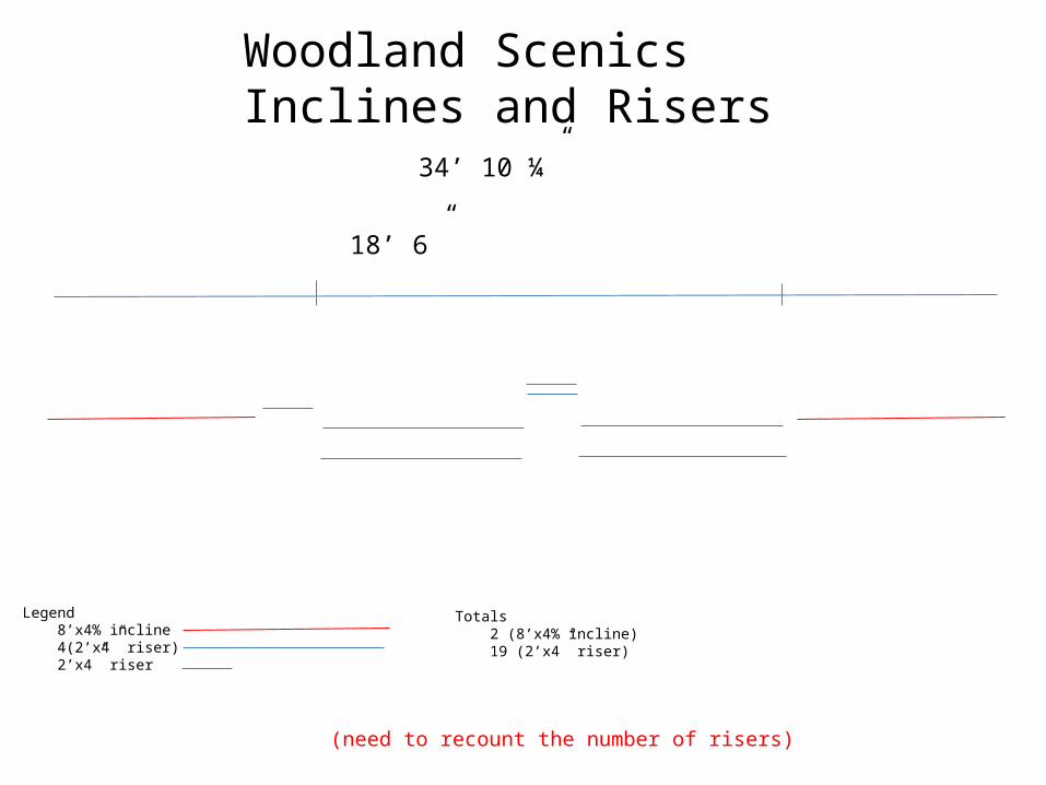
9’ 3 ¼” 18’ 6” 8’
34’ 10 ¼”
Legend 8’x4% incline 4(2’x4” riser) 2’x4” riser
Totals 2 (8’x4% incline) 19 (2’x4” riser)
Woodland ScenicsInclines and Risers
(need to recount the number of risers)
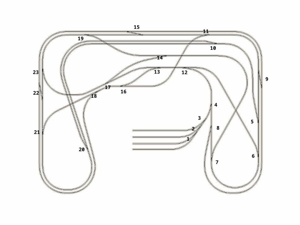
Sensors and
Blocks
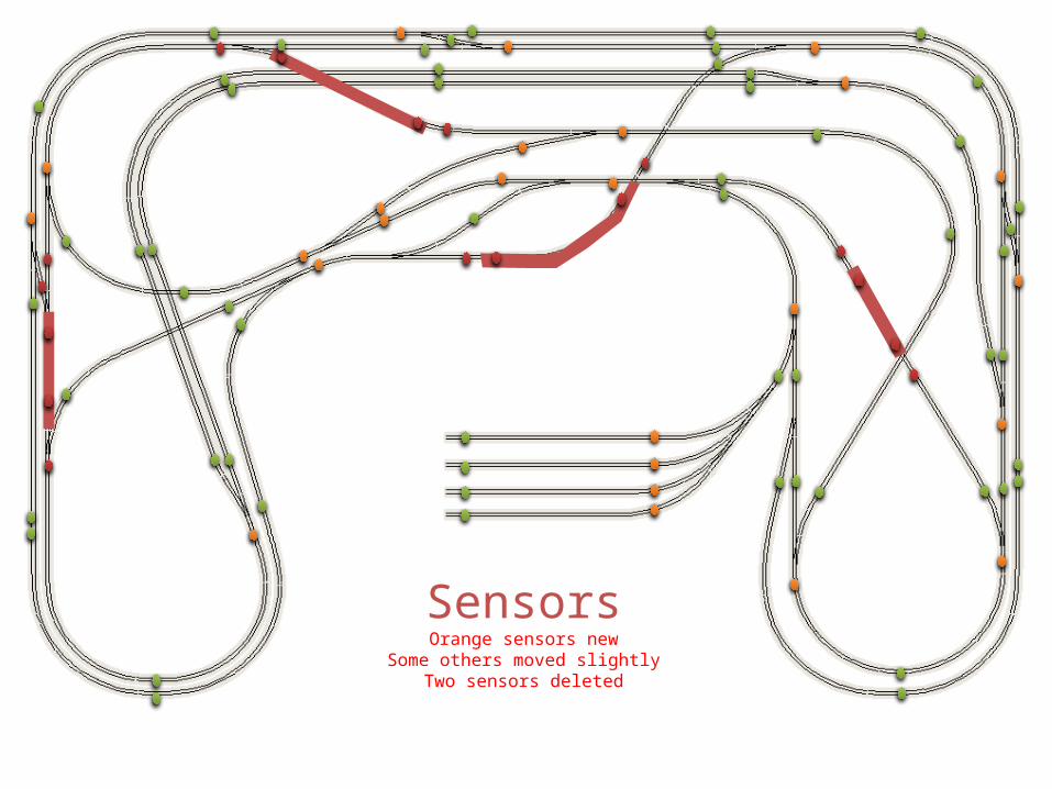
SensorsOrange sensors new
Some others moved slightlyTwo sensors deleted
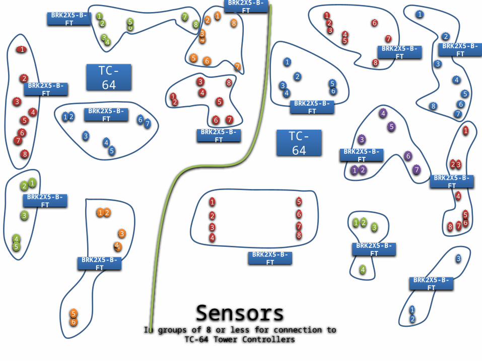
SensorsIn groups of 8 or less for connection to
TC-64 Tower Controllers
4
5
6
7
2
4
76
65
62
2
1 1
7
3
6
5
3
5
8
6
21
1 23
2 3
4
7
1
21
4
65
5
7865
2
3
2
1
81
5
2
4
3
3
4
8
8
34
3 4
2
65
2
43
5
54
1
32
51
1
1
2
4
76
4
3
5
6
78
4
3
4
7
78
1
6
3
1
3TC-64
4
TC-64
BRK2X5-B-FT
BRK2X5-B-FT
BRK2X5-B-FT
BRK2X5-B-FT
BRK2X5-B-FT
BRK2X5-B-FT
BRK2X5-B-FT
BRK2X5-B-FT
BRK2X5-B-FTBRK2X5-B-FT
BRK2X5-B-FT
BRK2X5-B-FT
BRK2X5-B-FT
BRK2X5-B-FT
BRK2X5-B-FT
1
7
2
8
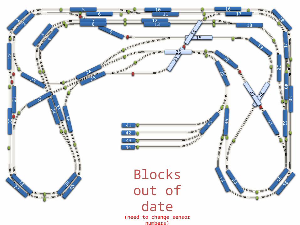
Blocksout of date
(need to change sensor numbers)
4039
36
2233
3837
12
23
32
3435
2524
34
315
6
9
7
5554
53
812
1011
1617
15
18
27
48
4719
14
13
26
20
28
46
56
21
29
5250
49
51
41
42
4344
30
45
DCC Electronicsfor Layout
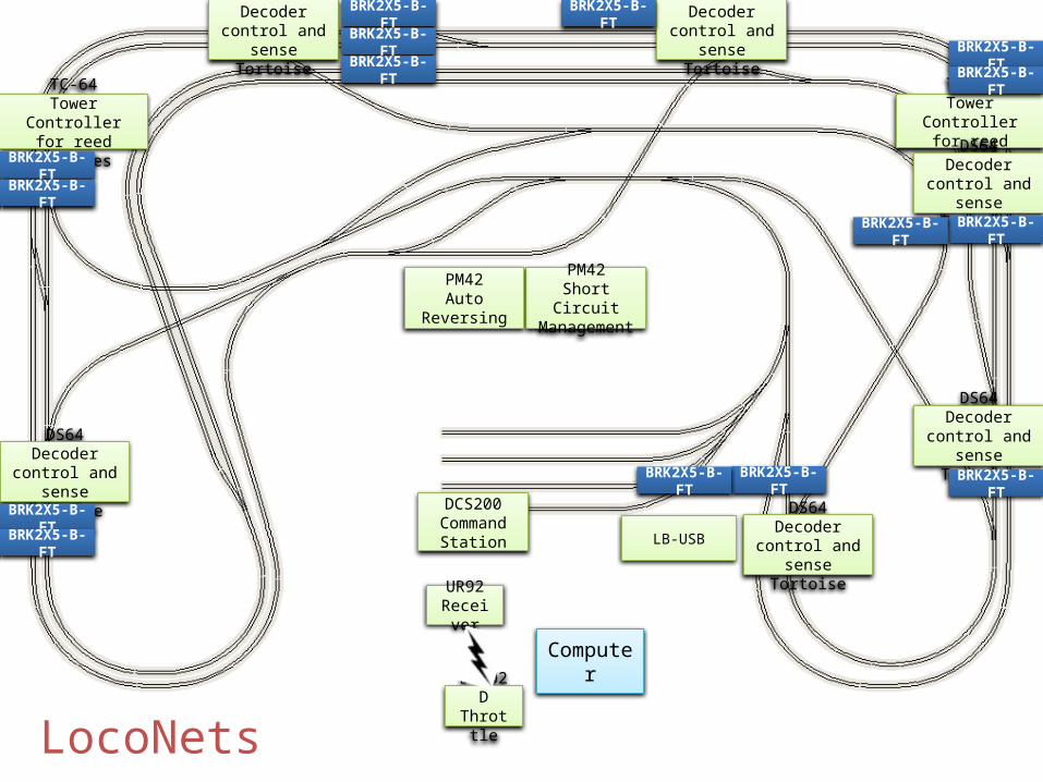
LocoNets
DS64 Decodercontrol and
sense Tortoise
Computer
PM42Short CircuitManagement
DCS200Command
Station LB-USB
DT402DThrottle
UR92Receiver
TC-64Tower Controllerfor reed switches
PM42Auto Reversing
TC-64Tower Controllerfor reed switches
DS64 Decodercontrol and
sense Tortoise
DS64 Decodercontrol and
sense Tortoise
DS64 Decodercontrol and
sense Tortoise
DS64 Decodercontrol and
sense Tortoise
DS64 Decodercontrol and
sense Tortoise
BRK2X5-B-FT
BRK2X5-B-FT
BRK2X5-B-FT
BRK2X5-B-FT
BRK2X5-B-FT
BRK2X5-B-FT
BRK2X5-B-FT
BRK2X5-B-FT
BRK2X5-B-FT
BRK2X5-B-FT
BRK2X5-B-FTBRK2X5-B-FT
BRK2X5-B-FTBRK2X5-B-FT BRK2X5-B-FT
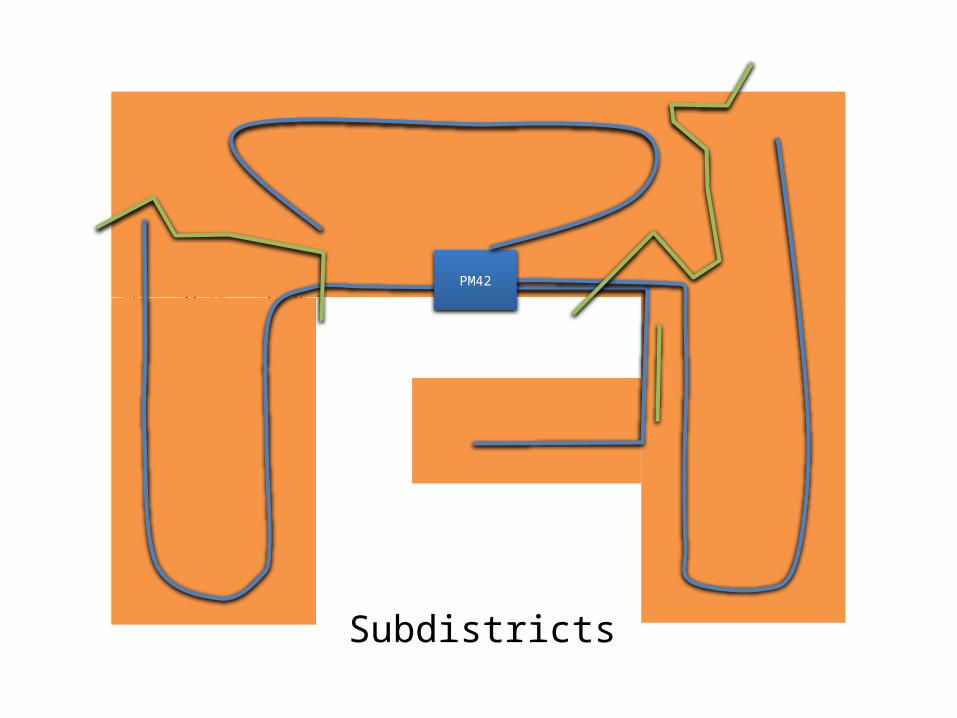
Subdistricts
PM42
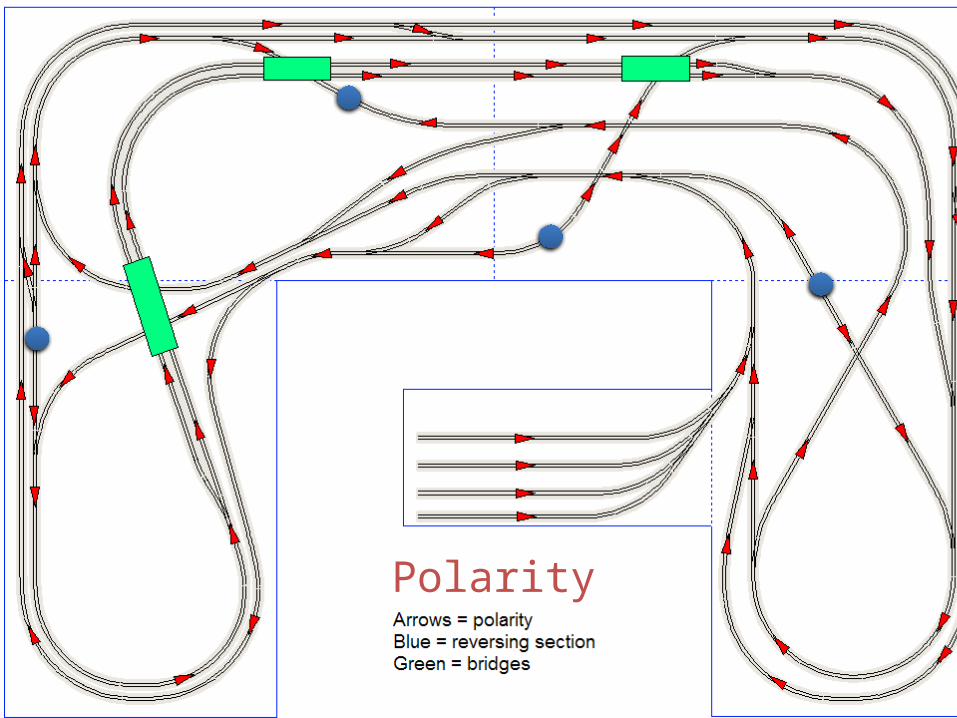
Polarity
PM42
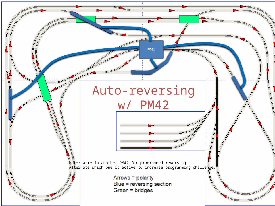
Auto-reversingw/ PM42
Later wire in another PM42 for programmed reversing.Alternate which one is active to increase programming challenge.
1
2
3
4
5
67
8
12
11
10
913
14
15
1617
18
19
20
21
22
23