DCC-100 Detector Control Module - Becker & Hicklbecker-hickl.com/pdf/dcc100_new.pdf · 1 Becker &...
15
1 Becker & Hickl GmbH March 2002 Printer HP 4500 PS Intelligent Measurement and Control Systems DCC-100 Detector Control Module PCI compatible detector control module for single photon counting experiments - Power supply and gain control for Hamamatsu H7422, H5783 or H5773 modules - Gain control for Hamamatsu R3809U MCP via FuG power supplies - Overload shutdown of detectors in conjunction with bh HFAC-26 preamps - Power supply for thermoelectric coolers, particularly for H7422 - Short circuit protected +12V, +5V and -5V power supply for preamps and detectors - Software switched +12V, +5V and -5V power supply outputs for detector on/off control - High current digital outputs for shutter and filter control - PCI card, software for Windows 95, 98, 2000 and NT 'Tel. +49 / 30 / 787 56 32 FAX +49 / 30 / 787 57 34 http://www.becker-hickl.com email: [email protected]
Transcript of DCC-100 Detector Control Module - Becker & Hicklbecker-hickl.com/pdf/dcc100_new.pdf · 1 Becker &...

1
Becker & Hickl GmbH March 2002 Printer HP 4500 PS Intelligent Measurement and Control Systems
DCC-100 Detector Control Module
PCI compatible detector control module for single photon counting experiments
- Power supply and gain control for Hamamatsu H7422, H5783 or H5773 modules - Gain control for Hamamatsu R3809U MCP via FuG power supplies - Overload shutdown of detectors in conjunction with bh HFAC-26 preamps - Power supply for thermoelectric coolers, particularly for H7422 - Short circuit protected +12V, +5V and -5V power supply for preamps and detectors - Software switched +12V, +5V and -5V power supply outputs for detector on/off control - High current digital outputs for shutter and filter control - PCI card, software for Windows 95, 98, 2000 and NT
'Tel. +49 / 30 / 787 56 32 FAX +49 / 30 / 787 57 34 http://www.becker-hickl.com email: [email protected]

2
Contents Introduction..............................................................................................................................................................3 Structure of the DCC-100 ........................................................................................................................................3
Detector control blocks .......................................................................................................................................3 High Current Switch Block .................................................................................................................................4 Power supply for thermoelectric cooler ..............................................................................................................4
Applications .............................................................................................................................................................5 Controlling H5783 and H5773 photosensor modules .........................................................................................5 Controlling the H7422 and H8632......................................................................................................................5 Controlling an R3809U MCP PMT ....................................................................................................................6 Controlling PMH-100 detectors ..........................................................................................................................6 Controlling Shutters ............................................................................................................................................7
Installation ...............................................................................................................................................................8 Requirements to the Computer............................................................................................................................8 Installation of the DCC-100 Software.................................................................................................................8 Software Update..................................................................................................................................................8
Update from the Web .....................................................................................................................................8 Installation of the DCC-100 Module...................................................................................................................9
Shutdown of High Current Switches..............................................................................................................9 Software .................................................................................................................................................................10
Startup Panel .....................................................................................................................................................10 Main Panel ........................................................................................................................................................10
Power-On State ............................................................................................................................................10 State after Software Start..............................................................................................................................10 Controls for Power Outputs and Detector Gain ...........................................................................................11 Detector Overload ........................................................................................................................................11 High Current Switches .................................................................................................................................12 Disable Output Function ..............................................................................................................................12 Cooler Control..............................................................................................................................................12
Saving and Loading the Setup...........................................................................................................................12 Pin Assignment ......................................................................................................................................................13 Specification ..........................................................................................................................................................14 Index ......................................................................................................................................................................15
3
Introduction The DCC-100 module is used to control detectors in conjunction with bh photon counters. It can be used to control the gain of the Hamamatsu H7422, H5783, H6783 or similar photosensor modules by software. The gain of MCPs and PMTs can be controlled via the FuG HCN-14 high voltage power supply. In conjunction with bh preamplifiers, overload shutdown of the detectors can be achieved. Furthermore, the DCC-100 delivers the current for thermoelectric coolers, e.g. for the Hamamatsu H7422. High current digital outputs are available for shutter or filter control. The DCC-100 is a PCI module for IBM compatible computers. It works under Windows 95, 98, 2000 and NT.
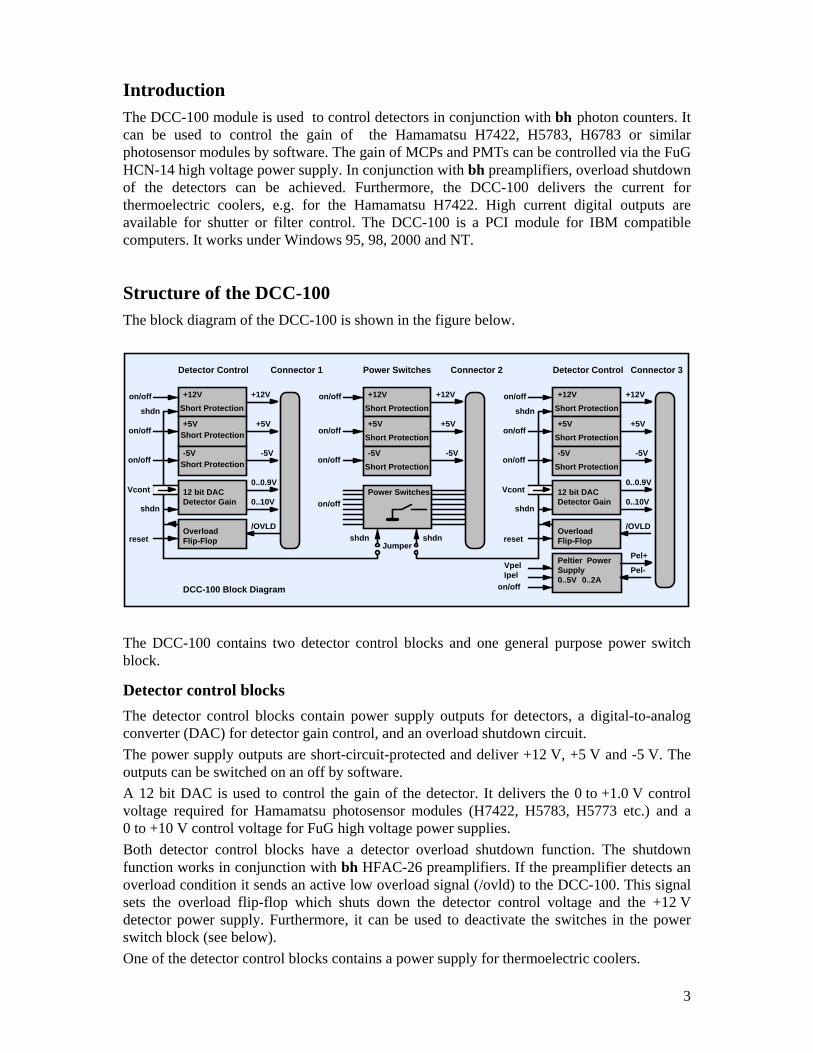
Structure of the DCC-100 The block diagram of the DCC-100 is shown in the figure below.
+12VShort Protection
on/off
Short Protection
Short Protection
+5V
-5V
on/off
OverloadFlip-Flop
+12V
+5V
-5V
0..0.9V
0..10V
/OVLD
on/off
Vcont
reset
shdn
shdn
Connector 1
+12Von/off
+5V
-5V
on/off
OverloadFlip-Flop
+12V
+5V
-5V
0..0.9V
0..10V
/OVLD
on/off
Vcont
reset
shdn
shdn
Connector 3
+12Von/off
+5V
-5V
on/off
+12V
+5V
-5Von/off
Power Switcheson/off
Connector 2
shdn shdn
Peltier PowerSupply0..5V 0..2A
Pel+
Pel-VpelIpel
on/off
Jumper
Detector Control Detector ControlPower Switches
DCC-100 Block Diagram
12 bit DAC 12 bit DACDetector GainDetector Gain
Short Protection
Short Protection
Short Protection
Short Protection
Short Protection
Short Protection
The DCC-100 contains two detector control blocks and one general purpose power switch block.
Detector control blocks The detector control blocks contain power supply outputs for detectors, a digital-to-analog converter (DAC) for detector gain control, and an overload shutdown circuit. The power supply outputs are short-circuit-protected and deliver +12 V, +5 V and -5 V. The outputs can be switched on an off by software. A 12 bit DAC is used to control the gain of the detector. It delivers the 0 to +1.0 V control voltage required for Hamamatsu photosensor modules (H7422, H5783, H5773 etc.) and a 0 to +10 V control voltage for FuG high voltage power supplies. Both detector control blocks have a detector overload shutdown function. The shutdown function works in conjunction with bh HFAC-26 preamplifiers. If the preamplifier detects an overload condition it sends an active low overload signal (/ovld) to the DCC-100. This signal sets the overload flip-flop which shuts down the detector control voltage and the +12 V detector power supply. Furthermore, it can be used to deactivate the switches in the power switch block (see below). One of the detector control blocks contains a power supply for thermoelectric coolers.

4
High Current Switch Block The high current switch block contains power supply outputs for detectors and preamplifiers and eight high-current MOSFET switches to operate shutters, motors or magnetic actuators. The power supply outputs are short-circuit-protected and deliver +12 V, +5 V and -5 V. The outputs can be switched on an off by software. The MOSFET switches are able to switch currents up to 2A and voltages up to 20V. One side of each switch is connected to ground, the other side is available at the output connector. The switches are not short circuit protected. The high current switches can be shut down (i.e. set into the non-conducting state) by one or both overload signals from the detector control blocks. The configuration is set by jumpers on the DCC-100 board, see ‘Configuration of Power Switch Shutdown’.
Power supply for thermoelectric cooler Power supply for thermoelectric coolers is available at connector 3. The output delivers up to 5 V and 2 A. Both voltage and current can be selected by software. The device automatically controls either the output voltage or the output current. Voltage control is active as long as the current through the load is smaller than the current limit set by the software. When the current through the load reaches the current limit the device automatically switches to current control. A block diagram is shown in the figure below.
SwitchingRegulator
+12Vfrom PC
feedback -+
reference'current'reference
'voltage'
PEL+
PEL-
Cooler
+
-
0.25 Ohm
Power supply for cooler
R1
R2 R3
A1D1
A switching regulator is used to generate the supply current for the cooler. The cooling current flows through the sensing resistor R3. As long as the voltage at R3 is smaller than the reference voltage at A1 (‘current’ reference) A1 is inactive and the switching regulator works as a normal voltage stabiliser. If the voltage at R3 exceeds the reference voltage at A1, the amplifier becomes active, and, via D1, overwrites the feedback voltage of the switching regulator. This causes the regulator to reduce the output voltage until the voltage at R3 equals the reference of A1. Please note that the current control can work only if the cooling current flows back into the ’PEL-‘ pin of the DCC-100. Therefore make sure that the ‘-‘ side of the cooler is not connected to ground. Moreover, make sure that you don’t reverse the ’PEL+‘ and ’PEL-‘ lines. This would heat the detector instead of cooling it and probably result in severe damage of the detector assembly.
5
Applications Some applications of the DCC-100 are described below.
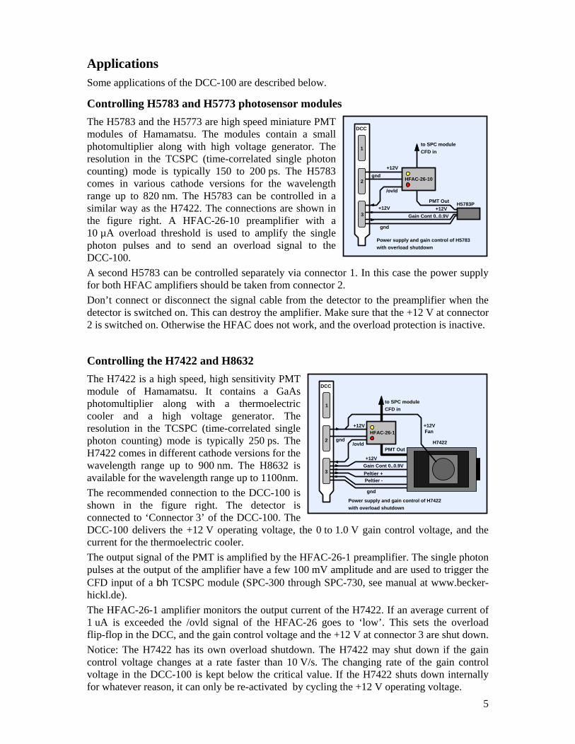
Controlling H5783 and H5773 photosensor modules The H5783 and the H5773 are high speed miniature PMT modules of Hamamatsu. The modules contain a small photomultiplier along with high voltage generator. The resolution in the TCSPC (time-correlated single photon counting) mode is typically 150 to 200 ps. The H5783 comes in various cathode versions for the wavelength range up to 820 nm. The H5783 can be controlled in a similar way as the H7422. The connections are shown in the figure right. A HFAC-26-10 preamplifier with a 10 µA overload threshold is used to amplify the single photon pulses and to send an overload signal to the DCC-100. A second H5783 can be controlled separately via connector 1. In this case the power supply for both HFAC amplifiers should be taken from connector 2. Don’t connect or disconnect the signal cable from the detector to the preamplifier when the detector is switched on. This can destroy the amplifier. Make sure that the +12 V at connector 2 is switched on. Otherwise the HFAC does not work, and the overload protection is inactive.
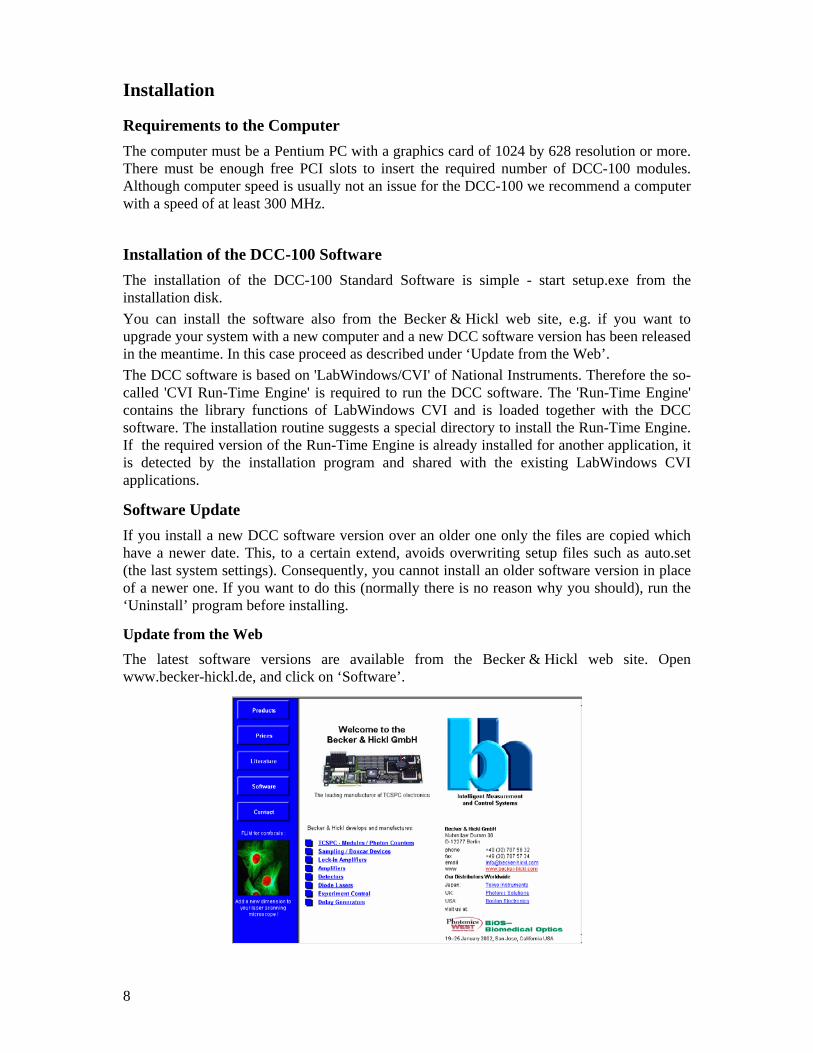
Controlling the H7422 and H8632 The H7422 is a high speed, high sensitivity PMT module of Hamamatsu. It contains a GaAs photomultiplier along with a thermoelectric cooler and a high voltage generator. The resolution in the TCSPC (time-correlated single photon counting) mode is typically 250 ps. The H7422 comes in different cathode versions for the wavelength range up to 900 nm. The H8632 is available for the wavelength range up to 1100nm. The recommended connection to the DCC-100 is shown in the figure right. The detector is connected to ‘Connector 3’ of the DCC-100. The DCC-100 delivers the +12 V operating voltage, the 0 to 1.0 V gain control voltage, and the current for the thermoelectric cooler. The output signal of the PMT is amplified by the HFAC-26-1 preamplifier. The single photon pulses at the output of the amplifier have a few 100 mV amplitude and are used to trigger the CFD input of a bh TCSPC module (SPC-300 through SPC-730, see manual at www.becker-hickl.de). The HFAC-26-1 amplifier monitors the output current of the H7422. If an average current of 1 uA is exceeded the /ovld signal of the HFAC-26 goes to ‘low’. This sets the overload flip-flop in the DCC, and the gain control voltage and the +12 V at connector 3 are shut down. Notice: The H7422 has its own overload shutdown. The H7422 may shut down if the gain control voltage changes at a rate faster than 10 V/s. The changing rate of the gain control voltage in the DCC-100 is kept below the critical value. If the H7422 shuts down internally for whatever reason, it can only be re-activated by cycling the +12 V operating voltage.
to SPC moduleCFD in
HFAC-26-10
PMT Out
/ovld
+12VGain Cont 0..0.9V
+12V
DCC
H5783P
Power supply and gain control of H5783with overload shutdown
+12V
1
2gnd
3
gnd
to SPC moduleCFD in
HFAC-26-1
PMT Out/ovld
+12VGain Cont 0..0.9VPeltier +Peltier -
Fan+12V
DCC
H7422
Power supply and gain control of H7422with overload shutdown
+12V
1
gnd2
3
gnd

6
Don’t connect or disconnect the signal cable from the detector to the preamplifier when the detector is switched on. This can destroy the amplifier. Make sure that the +12 V at connector 2 is switched on. Otherwise the HFAC does not work, and the overload protection is inactive.
Controlling an R3809U MCP PMT The Hamamatsu R3809U is the fastest photon counting detector currently available. It uses a microchannel plate for electron multiplication. In the TCSPC mode a time resolution of less than 30 ps (fwhm) can be achieved. MCP PMTs are extremely sensitive to overload. Because the microchannels are continuously destroyed by sputtering the lifetime of the detector is limited. The degradation effect is not noticeable under normal operating conditions. However, overloading the detector can rapidly exhaust the residual lifetime. Therefore, MCP PMTs should always be operated with overload protection, or at least with an overload indicator. The figure right shows how an R3809U MCP can be operated with overload protection. An FuG HCN-14-3500 is used as an high voltage power supply for the R3809U. The HCN-14 is available with a 0 to 10 V control input. The high voltage is proportional to the control voltage. Therefore, the detector operating voltage can be controlled by the DCC-100 and be shut down on overload. For overload detection, the HFAC-26-01 preamplifier - with an overload threshold of 0.1 µA - is used. Notice: Please observe the usual safety rules when working with high voltage. Make sure that there is a reliable ground connection between the detector and the HV power supply. Don’t use broken cables, loose connectors or cables with insufficient insulation. Don’t connect or disconnect the signal cable from the detector to the preamplifier when the detector is switched on. This can destroy the amplifier. Make sure that you connected all ground connections. Missing ground connections can result in high voltage instability or unreliable overload shutdown. Make sure that the +12 V at connector 2 is switched on. Otherwise the HFAC does not work, and the overload protection is inactive.
Controlling PMH-100 detectors The PMH-100 of bh is an easy to use detector head that contains a Hamamatsu photosensor module, a preamplifier, and an optical and acoustical overload indicator. due to its compact design it has an excellent noise immunity and a TCSPC time resolution of 140ps to 200ps (fwhm of system response). Since there is no overload signal available from the PMH-100 it cannot be automatically shut down on overload. Up to three detectors can, however, switched on and off via the DCC-100. By connecting the detectors to a bh SPC module via a HRT-41 or HRT-81 router the signals of all detectors can be recorded simultaneously. Or, by
to SPC moduleCFD in
HFAC-26-01
MCP Out
/ovld
HV Cont 0..10V
+12V
DCC
Overload shutdown for R3809U MCP
R3809U
HV
gnd
/ovld
HCNFuG
gnd
DCC
Switching on/off PMH-100 detectors
+12V switchable
+12V switchable
to SPC, CFD
PMH-100
PMH-100
PMH-100+12V switchable
gnd
gnd
gnd
HRT-41RoutingModule
1
2
3

7
switching only one detector on, the desired detector can be selected for measurement. The configuration is exceptionally useful for laser scanning microscopes which normally use several detectors in different light paths.
Controlling Shutters Shutters or other actuators can be controlled via the high current switches of connector 2. The switches can operate a voltage up to 20 V and up to 2 A. The power supply for the external load can be taken from connector 2 if a current of 100 mA at +12 V or 200 mA at +5 V is not exceeded. For higher currents an external power supply must be used. Since shutters and other magnetic devices are inductive loads a flyback diode must be connected across the load. For supply voltage up to 12 V a resistor can be connected in series with the flyback diode to achieve a faster turn-off time. The value of the resistor should be about the DC resistance of the actuator or shutter coil. The switches can automatically be shut down (i.e. set into the non-conducting state) when an overload condition occurs at connector 1 or connector 3. Which of the overload inputs is used for shutdown can be selected by jumpers on the DCC-100 board, see ‘Shutdown of High Current Switches’. Sometimes it is required to lock a shutter in the ‘closed’ state as long as a potential overload condition persists. An example is a microscope with a mercury or halogen lamp. When the lamp is on, opening the shutter must be inhibited. A solution is shown in the figure right. The photodiode detects the light from the lamp, and the amplifier sends an ‘/ovld’ to the DCC-100. The signal can be connected parallel to the /ovld from the amplifier. As long as the lamp is on, /ovld remains ‘low’ and the shutter cannot be opened. This gives additional safety against detector damage. It must, however, be pointed out that an absolute safety against detector damage cannot be achieved in this way. If the lamp is switched on when the shutter is open it takes a few milliseconds until the overload is detected and the shutter closes. This can be enough to cause severe detector damage. Therefore, the best way is always an mechanical interlock so that the lamp path is closed when the detection path is opened.
DCC
b0 Out
+12V
+12V
b1 Out
Shutter
Filter
Actuator1
2
3
+12 to +20V
to switch
<+12V
to switch
Controlling shutters and filters
DCC
1
-
+
10p
100M
1k
BC850AD820
BPW34
/ovld
+12V
b0
Photodiodein front ofshutter
3
2
HFAC26
+12V
shutter
Detector
Photodiode
light path
off-closed
/ovld
Locking a shutter in a potential overload situation
8
Installation
Requirements to the Computer The computer must be a Pentium PC with a graphics card of 1024 by 628 resolution or more. There must be enough free PCI slots to insert the required number of DCC-100 modules. Although computer speed is usually not an issue for the DCC-100 we recommend a computer with a speed of at least 300 MHz.
Installation of the DCC-100 Software The installation of the DCC-100 Standard Software is simple - start setup.exe from the installation disk. You can install the software also from the Becker & Hickl web site, e.g. if you want to upgrade your system with a new computer and a new DCC software version has been released in the meantime. In this case proceed as described under ‘Update from the Web’. The DCC software is based on 'LabWindows/CVI' of National Instruments. Therefore the so-called 'CVI Run-Time Engine' is required to run the DCC software. The 'Run-Time Engine' contains the library functions of LabWindows CVI and is loaded together with the DCC software. The installation routine suggests a special directory to install the Run-Time Engine. If the required version of the Run-Time Engine is already installed for another application, it is detected by the installation program and shared with the existing LabWindows CVI applications.
Software Update If you install a new DCC software version over an older one only the files are copied which have a newer date. This, to a certain extend, avoids overwriting setup files such as auto.set (the last system settings). Consequently, you cannot install an older software version in place of a newer one. If you want to do this (normally there is no reason why you should), run the ‘Uninstall’ program before installing.
Update from the Web
The latest software versions are available from the Becker & Hickl web site. Open www.becker-hickl.de, and click on ‘Software’.

9
Click on ‘Download’, ‘Windows 95/98/NT/2000’. Choose the DCC-100 software and get a ZIP file containing the complete installation. Unpack this file into a directory of your choice and start setup.exe. The installation will run as usual. For a new software version we recommend also to download the corresponding manual. Click on ‘Literature’, ‘Manuals’ and download the PDF file. Please see also under ‘Applications’ to find notes about typical applications of the DCC in conjunction with bh photon counters.
Installation of the DCC-100 Module To install the DCC-100, switch off the computer and insert the DCC module(s). To avoid damage due to electrostatic discharge we recommend to touch the module at the metallic back shield. Then touch a metallic part of the computer with the other hand. Then insert the module into a free slot of the computer. The DCC-100 has a PCI interface. Windows has a list of PCI devices, and on the start of the system it automatically assigns the required hardware resources to the components of this list. When the computer is started first time with the DCC inserted Windows detects the DCC and updates the list of hardware components. Therefore it may ask for driver information from a disk. Although this information is not actually required for the DCC you should select the driver information file from the driver disk delivered with the module. If you don’t have the driver disk, please download the driver file from www.becker-hickl.com or www.becker-hickl.de, ‘Software’, ‘Windows 95/98/NT/2000’ ‘Device drivers for bh modules’.
Shutdown of High Current Switches
The high current switches can be shut down (i.e. set into the non-conducting state) by one or both overload signals from the detector control blocks. The configuration is set by jumpers on the DCC-100 board. The location of the jumpers is shown in the figure below. If the jumpers ‘SHDN1’ or ‘SHDN3’ are set the high current switches are deactivated when an active ‘/overload’ signal is detected at connector 1 or connector 3, respectively. If both jumpers are set the switches are deactivated by both ‘/overload’ signals. To operate the peltier cooling unit of an H7422 or PMC-100 detector the jumper next to the output connector must be removed (opened). Please make sure that the jumper at the connector which is NOT attached to an H7422 (PMC-100 ) is closed if only one detector is used. NEVER CLOSE BOTH JUMPERS SIMULTANEOUSLY. Please note: If two H7422 ( PMC-100 ) detectors are operated simultaneously the cooling units of both detectors are supplied in a series connection. As a consequence the sliders to control the coolers are used in common.
DCC
1
2
3
Remove jumperwhen connecting a H7422 or PMC-100
Close jumper ONLY if
J1
J3
J1 is removed !
to connector 1

10
Software
Startup Panel The DCC standard software is able to control up to four DCC-100 modules. The startup window is shown in the figure below. The installed modules are marked as ‘In use’ and shown with their serial number, PCI address and slot number. When the startup window appears, click on ‘OK’ to open the main window of the DCC software. The software runs a simple hardware test when it initialises the modules. If an error is found, a message ‘Hardware Errors Found’ is given and the corresponding module is marked red. In case of non-fatal hardware errors you can start the main window by selecting ‘Hardware Mode’ in the ‘Change Mode’ panel. Please note that this feature is intended for trouble shooting and repair rather than for normal use.
Main Panel The main panel is shown in the figure right. The panel contains the controls for the power supply outputs, the high current switches, and for the peltier cooling.
Power-On State
Before the software takes control over the DCC the DCC control registers are in an undefined state. To avoid that the detectors are activated and possibly operated at a too high gain, after power-on the detector overload flip-flops are in the ‘Overload Shutdown’ state. That means, the +12V and the detector control voltages at connector 1 and 3 are shut down. If the jumpers for the shutdown of the high current switches are set also the switches are in the ‘off’ state. When the DCC software starts, it loads the previously used parameters into the DCC registers.
State after Software Start
When the DCC software starts, it automatically reloads the settings of the last use. These setting are saved an a file ‘auto.set’ which is updated every time when you exit the DCC software. After a software start, the DCC outputs are activated only if the ‘Enable Outputs on Startup’ option is switched on. ‘Enable Outputs on Startup’ can be switched on and off under ‘Parameters’, see figure right. We recommend to use the
Startup Panel
DCC main panel after power-on. ‘Enable
Outputs on Startup’ is switched off.
‘Enable Outputs on Startup’ option

11
automatic enable only if detector damage or any hazard due to high voltage is reliably excluded. If the outputs are disabled they can be enabled via the ‘Enable Outputs’ button at the bottom of the main panel.
Controls for Power Outputs and Detector Gain
The main panel is structured into ‘Connector 1’, ‘Connector 2’, ‘Connector 3’, and ‘Cooling’. To switch on or off one of the output signals click on the corresponding button. The detector gain control signals are changed by dragging the vertical bars or by typing in a value between 0 and 100%. Please note, that the Gain / HV signals control the high voltage of the detectors. Therefore, the detector gain is not proportional to the control signal. For PMTs and MCPs the relation is approximately
GAIN = Vcontrol n
with n ranging from 2.5 to 5. Therefore, the relation is highly nonlinear, and the PMT gain varies over several orders of magnitude. Don’t be surprised that photon counting works only at a HV setting close to the maximum.
Detector Overload
If a PMT overload is detected the ‘OVLD’ light of the corresponding connector turns on and a warning (flashing ‘!’) is issued. At the same time the detector control signal and the +12 V at the corresponding connector are shut down. You can also disable the high current switches on overload, e.g. to close shutters. To disable the switches from the overload flip-flops of connector 1 or 2 jumpers on the DCC board have to be set. To switch on the detector(s) after an overload shutdown, click on the ‘RESET OVLD’ button. Make sure that the overload has been removed before you reset the detectors. Safety note: Please make sure that you don’t exceed the maximum values for your detector(s). Particularly, if you control a HV power supply, make sure that it is safe to turn on or increase the voltage. Although the DCC-100 contains some safety features, such as detector shutdown at power-on or overload, it cannot be made safe in terms of operator errors, such as turning on HV power supplies with open or wrong connected output cables, or exceeding the maximum operating voltage for a given detector. bh will not take responsibility for accidents or detector damage resulting from setting or loading values exceeding maximum values for a given experiment setup.
DCC main panel, detectors activated
DCC main panel, after overload

12
High Current Switches
The high current switches can be switched on and off independently by the control buttons under ‘Connector 2’. All switches can be disabled (i.e. switched into the non-conducting state) be the ‘Disable Outputs’ button. The high current switches can be shut down (i.e. set into the non-conducting state) by one or both overload signals from the detector control blocks. The configuration is set by jumpers on the DCC-100 board, see ‘Installation’, ‘Shutdown of High Current Switches’. If the high current switches have been deactivated by detector overload they must be explicitly switched on after the overload condition is removed.
Disable Output Function
The power supply outputs, the detector gain signals and the high current switches can be disabled and enabled by the ‘Disable Output’ or ‘Enable Output’ button. You can automatically disable all outputs at the start of the software to bring the system in a safe state before you switch on the detectors. The ‘Disable on Start’ function can be switched on and off under ‘Parameters’.
Cooler Control
The cooling current can be switched on and off by clicking on the ‘ON’ button. To control the cooling power, you can set an output voltage and an output current. Of course, setting voltage and current in an electrical circuit simultaneously is impossible. The cooling power supply works in a way that the voltage at the output is controlled as long as the specified current is not reached. When the specified current is reached current control takes over and the current is controlled. In other words, the cooling is controlled in way that neither the selected voltage nor the selected current is exceeded. Current control is indicated by the ‘Curr Lmt’ light.
Saving and Loading the Setup To load or to save the DCC setup, click on ‘Main’ in the menu bar and select ‘Save’ or ‘Load’. The ‘Save’ and ‘Load’ menus are shown below. When you save a setup you first have to enter a file name or to select a file name by clicking into the ‘file name’ field. There you can also change to other directories or drives. A history of file names is available via the ‘∇’ button right of the file name. Then you can - but need not - type in the operator name, a company name, and a description for what your setup is.

13
Loading a setup file works in a similar way. Click on the ‘file name’ field and select the correct setup file. In the ‘File Info’ field you will see the information typed in when the file was saved. If it is the right file, click on ‘Load’. Note: Please make sure that you load the right file for your experiment setup. Although the DCC-100 contains some safety features, such as detector shutdown at power-on or overload, it cannot be made safe in terms of operator errors, such as turning on HV power supplies with open or wrong connected output cables, or exceeding the maximum operating voltage for a given detector. bh will not take responsibility for accidents or detector damage resulting from setting or loading values exceeding maximum values for a given experiment setup.
Pin Assignment
Connector 1 15pin HD-SubD Pin Signal 1 +5V out switchable 2 3 4 5 GND 6 -5V out switchable 7 8 9 10 +12V out switchable, ovld sdwn 11 -12V out 12 0...+10V HV cont., ovld sdwn 13 0...+1.0V gain cont., ovld sdwn 14 /OVLD1 input 15 GND
Connector 2 15pin HD-SubD Pin Signal 1 +5V out switchable 2 Bit0 open drain out 3 Bit1 open drain out 4 Bit2 open drain out 5 GND 6 -5V out switchable 7 Bit3 open drain out 8 Bit4 open drain out 9 Bit5 open drain out 10 +12V out switchable 11 -12V out 12 Bit6 open drain out 13 Bit7 open drain out 14 15 GND
Connector 3 15pin HD-SubD Pin Signal 1 +5V out switchable 2 Peltier + 3 Peltier + 4 Peltier + 5 GND 6 -5V out switchable 7 Peltier - 8 Peltier - 9 Peltier - 10 +12V out, switchable, ovld sdwn 11 -12V out 12 0...+10V HV cont., ovld sdwn 13 0...+1.0V gain cont., ovld sdwn 14 /OVLD3 input 15 GND

14
Specification Power Supply Outputs (Connectors 1 to 3) Max. Current at +12 V 100 mA Short Circuit Current +12 V 50 mA 1)
Time from /OVLD to disable +12V 10 ms 2) Output current in disabled state, +12 V < 0.5 mA Max. Current at +5 V 200 mA Short Circuit Current +5 V 60 mA 1) Output current in disabled state, +5 V < 0.5 mA Max. Current at -5 V 200 mA Short Circuit Current -5 V 60 mA 1) Output current in disabled state, -5 V < 0.5 mA Max. Current at -12 V total 120 mA, single output 60 mA Short Circuit Current -12 V No short protection. Don’t short longer than 1s 1) Foldback Characteristics, don’t short several outputs simultaneously for more than 20s 2) Connectors 1 and 3 only. 250 Ω load, time from +12V to +6V output voltage.
Detector Gain Control (Connectors 1 and 3) Resolution 12 bit Voltage Range Pin 12 0 to +10 V Load at Pin 12 min. 1 kΩ Output Resistance at Pin 12 100 Ω Voltage Range Pin 13 0 to +1.0 V Load at Pin 13 min. 1 kΩ Output Resistance at Pin 13 100 Ω Output Time Constant 100 ms
Overload Shutdown Overload inputs at connector 1 and 3 TTL, active Low, Pull-up resistor 10 kΩ Overload Reset By Software and at Power-ON
High Current Switches (Connector 2) Typical ‘On’ Resistance, 25°C 70 mΩ Max. Switch Current, Single Switch 2 A Max. Switch Current, Sum of all Switches 5 A3) Max. turn-off Voltage at Switch 20 V Turn-on and turn-off transition time, Load 10 Ω 100 ns Disable on /OVLD if configured by jumpers Disable Transition Time < 1 us Time from /OVLD to Disable < 2 us 3) Both GND pins used
Supply for Thermoelectric Coolers (Connector 3) Output Voltage 0 to 5 V Output Current 0 to 2 A Resolution of Output Voltage and Current 12 bit Output Resistance 0.4 Ω 4) Output Capacitance 300 uF Output Ripple < 5 mV 4) All pins parallel
PC Interface Dimensions 160 mm x 106 mm x 15 mm Interface / Connector PCI Register Access I/O only Supply Current, +5V, No Load, typ. value 0.6 A Supply Current, +5V, Maximum Load, typ. value 1.2 A Supply Current, +12V, No Load, typ. value 0.2 A Supply Current, +12V, Maximum Load, typ. value 1.6 A

15
Index /ovld signal 5 Block Diagram of DCC-100 3 Computer, Requirements for DCC 8 Connectors, Pin Assignment 13 Controls, for Cooling 12 Controls, for Detector Gain 11 Controls, for High Current Switches 12 Controls, for Power Outputs 11 Cooler Control 4, 12 Cooling Current 4, 12 Cooling Voltage 4, 12 Current Limit Light 12 CVI Run-Time Engine 8 Detector Control 3 Detector Control Blocks 3 Detector Control Blocks, Overload Shutdown 3 Detector Control Signal 3 Detector Control, DAC 3 Detector Gain 11 Detector Overload 11 Detector Shutdown 11 Device Drivers 9 Disable on Start Function 12 Disable Outputs Button 12 Disable Outputs Function 12 Download, Manual 9 Download, Software 8 Driver Disk 9 Driver, for DCC-100 Module 9 Enable Outputs Button 12 Enable, outputs on startup 11 File, Save and Load 12 Flyback Diode 7 Gain Control Signal 5 H5773 5 H5783 5 H7422 5 H8632 5 Hardware Test 10 HCN-14-3500 6 HFAC-26 Preamplifier 5, 6 High Current Switches 4, 7 High Current Switches, Controls, for 12 High Current Switches, shutdown 4, 9 High Voltage Power Supply 6 High Voltage, Safety Rules 6 HRT-41 7 HRT-81 7 Inductive Load 7 Installation, of DCC Module 9 Installation, of DCC Software 8 Installation, of DCC-100 Driver 9 LabWindows/CVI 8 Load Setup 12
Main Panel 10 Manual, Download 9 Manual, pdf File 9 MCP 6 MCP, Lifetime 6 MCP, Overload 6 MCP, Power Supply 6 Microchannel Plate 6 Outputs, enable on startup 11 Overload Flip-Flop 3 Overload Light 11 Overload Shutdown 3, 10, 11 Overload Shutdown, via HFAC-26 Preamp 3, 5, 6 Overload Signal 3, 5 PEL+ and PEL- pins 4 Peltier Control 4, 12 Peltier Current 4, 12 Peltier Voltage 4, 12 Pin Assignment, of Connectors 13 PMH-100 6 Power Outputs, Switching ON/Off 11 Power Supply, for High Current Switches 7 Power Supply, for MCP 6 Power Supply, High Voltage 6 Power-On, State after 10 Preamplifier 5, 6 Preamplifier, for H5783 and H5773 5 Preamplifier, for H7422 5 Preamplifier, for MCP 6 R3809U 6 Reset, after Detector Shutdown 11 Router 7 Safety Notes 4, 6, 11, 13 Safety Notes, Cooler 4 Safety Notes, High Voltage 6 Save Setup 12 Setup, Load 12 Setup, Save 12 setup.exe 8 Shutdown, at Power-On 10 Shutdown, H7422 5 Shutdown, of Detectors 3, 11 Shutdown, of high current switches 4, 7, 9, 12 Shutter, Locking 7 Shutters 7 Software Start, State after 10 Software, for DCC-100 10 Software, Installation 8 Software, Update 8 Software, Update from the Web 8 Specification 14 Startup Panel 10 Structure of DCC-100 3 Thermoelectric Coolers 4