day/night Ultra Wide Dynamic Fixed Dome Camera User · Day/Night Ultra Wide Dynamic Fixed Dome...
32
Document 800-00031 – Rev A – 04/08 Day/Night Ultra Wide Dynamic Fixed Dome Camera User Guide NTSC / PAL HD4U HD4UX
Transcript of day/night Ultra Wide Dynamic Fixed Dome Camera User · Day/Night Ultra Wide Dynamic Fixed Dome...
Document 800-00031 – Rev A – 04/08
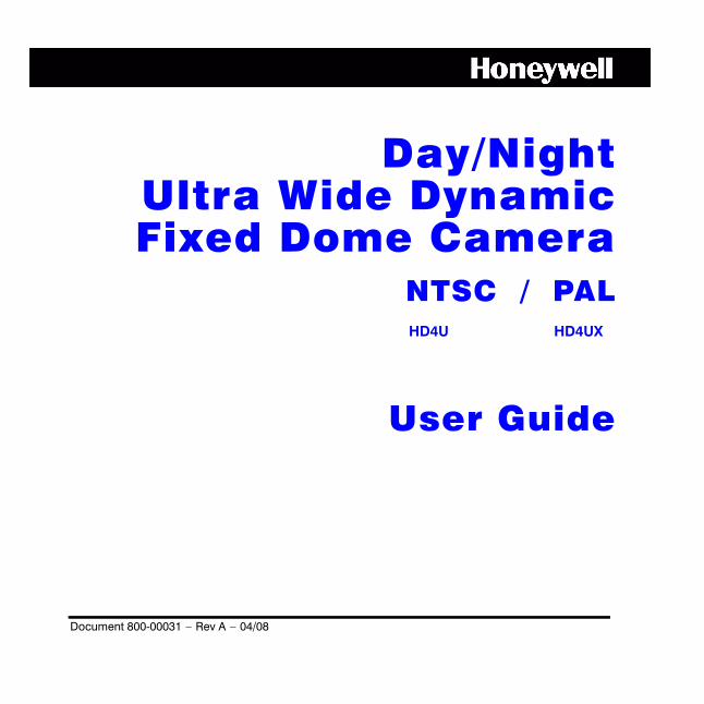
Day/NightUltra Wide DynamicFixed Dome Camera
User Guide
NTSC / PALHD4U HD4UX
2
Revisions
Issue Date Revisions
A 04/08 New document.
Document 800-00031 Rev A 304/08
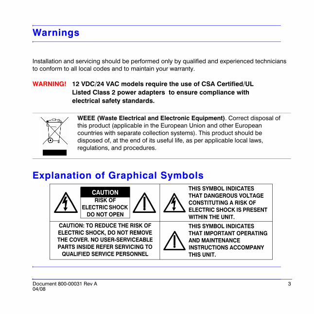
Warnings
Installation and servicing should be performed only by qualified and experienced technicians to conform to all local codes and to maintain your warranty.
WARNING! 12 VDC/24 VAC models require the use of CSA Certified/UL Listed Class 2 power adapters to ensure compliance with electrical safety standards.
Explanation of Graphical Symbols
WEEE (Waste Electrical and Electronic Equipment). Correct disposal of this product (applicable in the European Union and other European countries with separate collection systems). This product should be disposed of, at the end of its useful life, as per applicable local laws, regulations, and procedures.
RISK OF ELECTRIC SHOCK
DO NOT OPEN
CAUTION: TO REDUCE THE RISK OF ELECTRIC SHOCK, DO NOT REMOVE THE COVER. NO USER-SERVICEABLE PARTS INSIDE REFER SERVICING TO
QUALIFIED SERVICE PERSONNEL
THIS SYMBOL INDICATES THAT DANGEROUS VOLTAGE CONSTITUTING A RISK OF ELECTRIC SHOCK IS PRESENT WITHIN THE UNIT.
THIS SYMBOL INDICATES THAT IMPORTANT OPERATING AND MAINTENANCE INSTRUCTIONS ACCOMPANY THIS UNIT.
CAUTION
4
FCC Compliance Statement
Information to the User: This equipment has been tested and found to comply with the limits for a Class B digital device. Pursuant to Part 15 of the FCC Rules, these limits are designed to provide reasonable protection against harmful interference in a residential installation. This equipment generates, uses, and can radiate radio frequency energy and, if not installed and used in accordance with the instruction manual, may cause harmful interference to radio communications. However, there is no guarantee that interference will not occur in a particular installation.
If this equipment does cause harmful interference to radio or television reception, which can be determined by turning the equipment off and on, the user is encouraged to try to correct the interference. For example, try reorienting or relocating the receiving antenna, increasing the separation between the equipment and receiver, or connecting the equipment to an outlet on a different circuit.
Caution Changes or modifications not expressly approved by the party responsible for compliance could void the user’s authority to operate the equipment.
This Class B digital apparatus complies with Canadian ICES-003.
Manufacturer’s Declaration of Conformance
The manufacturer declares that the equipment supplied with this guide is compliant with the essential protection requirements of the EMC directive 2004/108/EC and the Low Voltage Directive LVD 2006/95/EC, conforming to the requirements of standards EN 55013 for emissions, EN 50130-4 for immunity, and EN 60065 for Electrical Equipment safety.
Document 800-00031 Rev A 504/08
ContentsIntroduction . . . . . . . . . . . . . . . . . . . . . . . . . . . . . . . . . . . . . . . . . . . . . . . . . . . . . . . . . . 6
Before You Begin . . . . . . . . . . . . . . . . . . . . . . . . . . . . . . . . . . . . . . . . . . . . . . . . . . . . . . 6Unpack Everything . . . . . . . . . . . . . . . . . . . . . . . . . . . . . . . . . . . . . . . . . . . . . . . . . . 6Equipment Required . . . . . . . . . . . . . . . . . . . . . . . . . . . . . . . . . . . . . . . . . . . . . . . . . 7
Installation . . . . . . . . . . . . . . . . . . . . . . . . . . . . . . . . . . . . . . . . . . . . . . . . . . . . . . . . . . . 8Mounting the Camera . . . . . . . . . . . . . . . . . . . . . . . . . . . . . . . . . . . . . . . . . . . . . . . . . . 8
Connecting Cables Through the Housing Base . . . . . . . . . . . . . . . . . . . . . . . . . . . . 9Connecting Cables Through the Side Conduit . . . . . . . . . . . . . . . . . . . . . . . . . . . 10Electrical Box Installations . . . . . . . . . . . . . . . . . . . . . . . . . . . . . . . . . . . . . . . . . . . 11
Connecting the Wiring . . . . . . . . . . . . . . . . . . . . . . . . . . . . . . . . . . . . . . . . . . . . . . . . . 13Adjusting the Camera . . . . . . . . . . . . . . . . . . . . . . . . . . . . . . . . . . . . . . . . . . . . . . . . . 13
Adjusting the Lens Focus . . . . . . . . . . . . . . . . . . . . . . . . . . . . . . . . . . . . . . . . . . . . 14
Camera Setup . . . . . . . . . . . . . . . . . . . . . . . . . . . . . . . . . . . . . . . . . . . . . . . . . . . . . . . 15Camera Functions . . . . . . . . . . . . . . . . . . . . . . . . . . . . . . . . . . . . . . . . . . . . . . . . . . . . 15OSD Menu Structure . . . . . . . . . . . . . . . . . . . . . . . . . . . . . . . . . . . . . . . . . . . . . . . . . . 15Configuring the WDR Presets . . . . . . . . . . . . . . . . . . . . . . . . . . . . . . . . . . . . . . . . . . . 16Optimizing the Camera Setup . . . . . . . . . . . . . . . . . . . . . . . . . . . . . . . . . . . . . . . . . . . 17Setting the Camera Image Properties . . . . . . . . . . . . . . . . . . . . . . . . . . . . . . . . . . . . . 19Setting the Day/Night Control . . . . . . . . . . . . . . . . . . . . . . . . . . . . . . . . . . . . . . . . . . . 21Restoring Settings . . . . . . . . . . . . . . . . . . . . . . . . . . . . . . . . . . . . . . . . . . . . . . . . . . . . 22Installing the Enclosure Cover . . . . . . . . . . . . . . . . . . . . . . . . . . . . . . . . . . . . . . . . . . . 23Routine Maintenance . . . . . . . . . . . . . . . . . . . . . . . . . . . . . . . . . . . . . . . . . . . . . . . . . . 23
Solving Common Technical Issues . . . . . . . . . . . . . . . . . . . . . . . . . . . . . . . . . . . . . . 24
Warranty and Service . . . . . . . . . . . . . . . . . . . . . . . . . . . . . . . . . . . . . . . . . . . . . . . . . 25
Specifications . . . . . . . . . . . . . . . . . . . . . . . . . . . . . . . . . . . . . . . . . . . . . . . . . . . . . . . 26Dimensions . . . . . . . . . . . . . . . . . . . . . . . . . . . . . . . . . . . . . . . . . . . . . . . . . . . . . . . 27
Cable Guidelines . . . . . . . . . . . . . . . . . . . . . . . . . . . . . . . . . . . . . . . . . . . . . . . . . . . . . 28
HD4U Mounting Template . . . . . . . . . . . . . . . . . . . . . . . . . . . . . . . . . . . . . . . . . . . . . . 29
6
Introduction
The unobtrusive, low-profile design of the HD4U/X CCTV Camera is ideal for indoor and outdoor installations in commercial and residential venues.
Before You BeginPlease read this guide carefully before you install the HD4U/X CCTV Camera.
Keep this guide for future reference.
Unpack EverythingCheck that the items received match those listed on the order form and packing slip. The HD4U/X packing box should include, in addition to this User Guide:
• One fully-assembled HD4U/X camera, including factory-installed pigtail power and video connectors
• One service monitor cable• One wall mount adapter plate• One HD4U/X hardware kit• One bag containing mounting screws• One Product warranty
If any parts are missing or damaged, contact the dealer you purchased the camera from or call Honeywell Customer Service (see Warranty and Service).
Document 800-00031 Rev A 704/08
Equipment RequiredYou will require the following tools to complete the installation:
• Phillips screwdriver• Tools supplied in the hardware kit (three Allen keys: one each for the security screw on the
lid, the conduit plug locking screw, and the lens locking screw)• Side-cutters
8
Installation
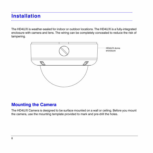
The HD4U/X is weather-sealed for indoor or outdoor locations. The HD4U/X is a fully-integrated enclosure with camera and lens. The wiring can be completely concealed to reduce the risk of tampering.
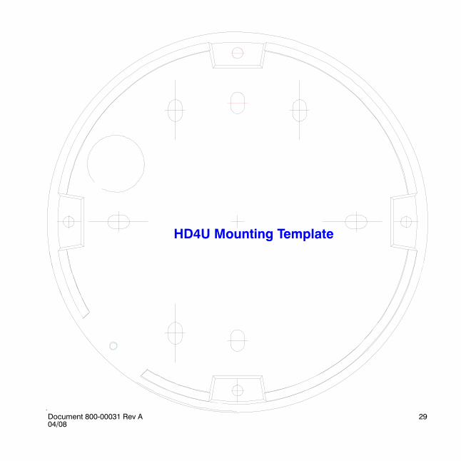
Mounting the CameraThe HD4U/X Camera is designed to be surface mounted on a wall or ceiling. Before you mount the camera, use the mounting template provided to mark and pre-drill the holes.
HD4U/X dome enclosure
Document 800-00031 Rev A 904/08
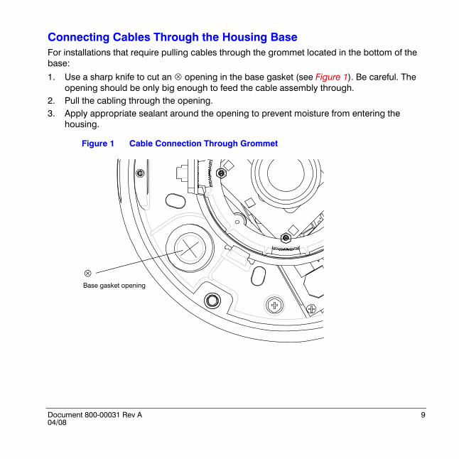
Connecting Cables Through the Housing BaseFor installations that require pulling cables through the grommet located in the bottom of the base:
1. Use a sharp knife to cut an ! opening in the base gasket (see Figure 1). Be careful. The opening should be only big enough to feed the cable assembly through.
2. Pull the cabling through the opening.3. Apply appropriate sealant around the opening to prevent moisture from entering the
housing.
Figure 1 Cable Connection Through Grommet
Base gasket opening
!
10
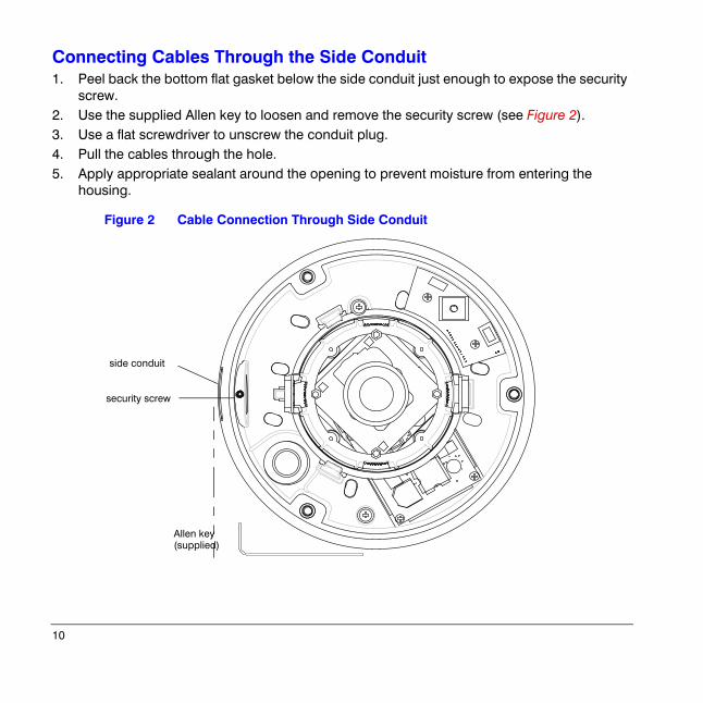
Connecting Cables Through the Side Conduit 1. Peel back the bottom flat gasket below the side conduit just enough to expose the security
screw.2. Use the supplied Allen key to loosen and remove the security screw (see Figure 2).3. Use a flat screwdriver to unscrew the conduit plug.4. Pull the cables through the hole.5. Apply appropriate sealant around the opening to prevent moisture from entering the
housing.
Figure 2 Cable Connection Through Side Conduit
security screw
Allen key (supplied)
side conduit
Document 800-00031 Rev A 1104/08
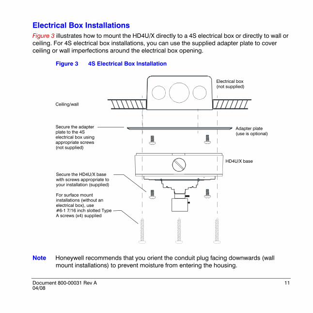
Electrical Box InstallationsFigure 3 illustrates how to mount the HD4U/X directly to a 4S electrical box or directly to wall or ceiling. For 4S electrical box installations, you can use the supplied adapter plate to cover ceiling or wall imperfections around the electrical box opening.
Figure 3 4S Electrical Box Installation
Note Honeywell recommends that you orient the conduit plug facing downwards (wall mount installations) to prevent moisture from entering the housing.
Electrical box (not supplied)
Adapter plate (use is optional)
HD4U/X base
Secure the adapter plate to the 4S electrical box using appropriate screws (not supplied)
Secure the HD4U/X base with screws appropriate to your installation (supplied)
For surface mount installations (without an electrical box), use #6-1 7/16 inch slotted Type A screws (x4) supplied
Ceiling/wall
12
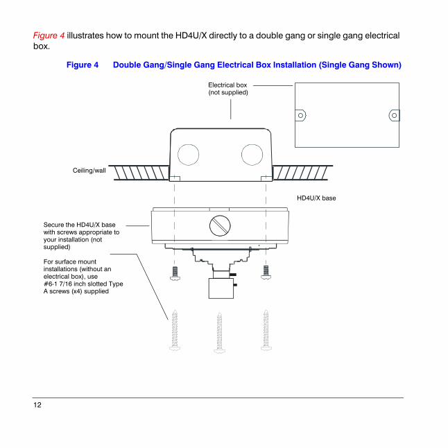
Figure 4 illustrates how to mount the HD4U/X directly to a double gang or single gang electrical box.
Figure 4 Double Gang/Single Gang Electrical Box Installation (Single Gang Shown)
Electrical box (not supplied)
HD4U/X base
Ceiling/wall
Secure the HD4U/X base with screws appropriate to your installation (not supplied)
For surface mount installations (without an electrical box), use #6-1 7/16 inch slotted Type A screws (x4) supplied
Document 800-00031 Rev A 1304/08
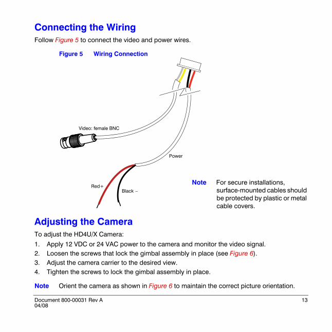
Connecting the WiringFollow Figure 5 to connect the video and power wires.
Figure 5 Wiring Connection
Adjusting the CameraTo adjust the HD4U/X Camera:
1. Apply 12 VDC or 24 VAC power to the camera and monitor the video signal.2. Loosen the screws that lock the gimbal assembly in place (see Figure 6).3. Adjust the camera carrier to the desired view.4. Tighten the screws to lock the gimbal assembly in place.
Note Orient the camera as shown in Figure 6 to maintain the correct picture orientation.
Red+Black –
Power
Video: female BNC
Note For secure installations, surface-mounted cables should be protected by plastic or metal cable covers.
14
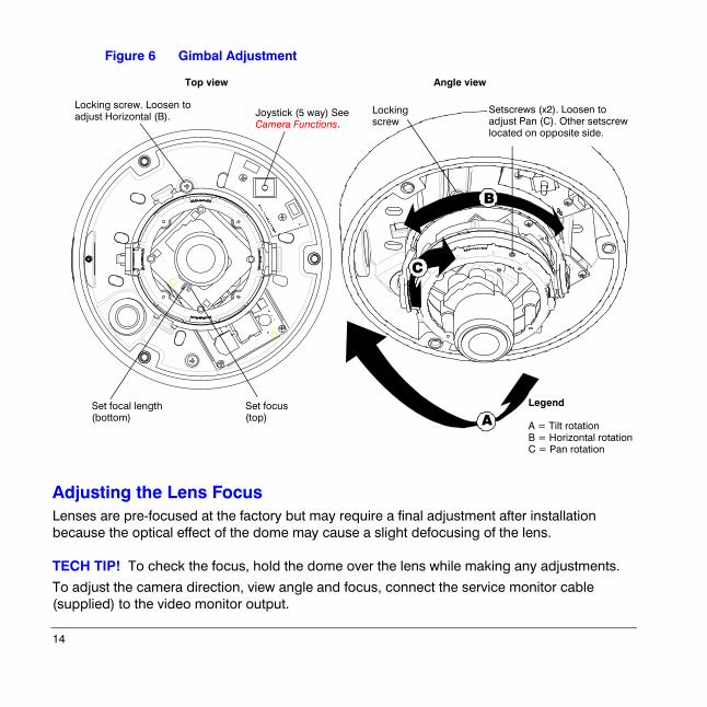
Figure 6 Gimbal Adjustment
Adjusting the Lens FocusLenses are pre-focused at the factory but may require a final adjustment after installation because the optical effect of the dome may cause a slight defocusing of the lens.
TECH TIP! To check the focus, hold the dome over the lens while making any adjustments.
To adjust the camera direction, view angle and focus, connect the service monitor cable (supplied) to the video monitor output.
A
B
C
Locking screw. Loosen to adjust Horizontal (B).
Set focus(top)
Set focal length(bottom)
Locking screw
Top view Angle view
Setscrews (x2). Loosen to adjust Pan (C). Other setscrew located on opposite side.
Joystick (5 way) See Camera Functions.
Legend
A = Tilt rotationB = Horizontal rotationC = Pan rotation

Document 800-00031 Rev A 1504/08
Camera Setup
Camera Functions
OSD Menu Structure
- Press down on the joystick and hold two seconds to access the MAIN MENU.- Press down to enter a screen or select a menu option.
!,"Move vertically to and between menus and options
“…” indicates submenus
To leave the screen and return to the previous menu, select PREVIOUS PAGE, and then press down on the joystick.
To save your changes, select SAVE & EXIT, and then press down on the joystick . Your settings remain in effect when power is turned off, then on again.
Select a menu, then press down the joystick to enter the submenu.
Move the joystick #, $ to change the status.>
MENUCAMERA SETUP ..VIEWING ..WDR PRESETS ..DAY/NIGHT SETUP ..VERSION INFO ..RESTORE DEFAULTS <NO>EXIT EXIT W/O SAVE.
#, $Move horizontally to and between menus and options
Joystick control (5 way)
!$
"#
WDR PRESETS DAY/NIGHT SETUP
MENU
CAMERA SETUP
VIEWING VERSION INFO
RESTORE DEFAULTS
EXIT
DIG SLOW SHUTTER …SYNC MODEAGC …WHITE BALANCEAI THOLD
PRESETSFLUORESCENT
4 Setup menus for easy programming
D/N CONTROL …NIGHT MODETDN DELAY
Menu:FW Rev:
SAVE & EXITEXIT W/O SAVE
FLIPID DISPLAY …SHARPNESSBRIGHTNESSRESOLUTIONCOLOR ADJ.
NOYES
16
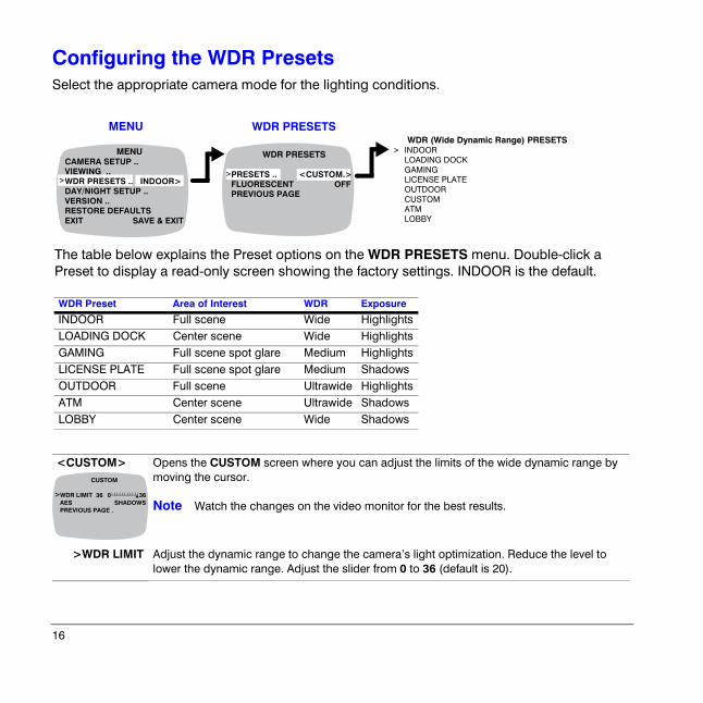
Configuring the WDR PresetsSelect the appropriate camera mode for the lighting conditions.
<CUSTOM> Opens the CUSTOM screen where you can adjust the limits of the wide dynamic range by moving the cursor.
Note Watch the changes on the video monitor for the best results.
>WDR LIMIT Adjust the dynamic range to change the camera’s light optimization. Reduce the level to lower the dynamic range. Adjust the slider from 0 to 36 (default is 20).
WDR (Wide Dynamic Range) PRESETSINDOORLOADING DOCKGAMINGLICENSE PLATEOUTDOORCUSTOMATMLOBBY
>
MENU
>
WDR PRESETS
>
MENUCAMERA SETUP ..VIEWING ..WDR PRESETS .. INDOOR>DAY/NIGHT SETUP ..VERSION ..RESTORE DEFAULTSEXIT SAVE & EXIT
WDR PRESETS
PRESETS .. <CUSTOM.>FLUORESCENT OFFPREVIOUS PAGE
WDR Preset Area of Interest WDR Exposure
INDOOR Full scene Wide HighlightsLOADING DOCK Center scene Wide HighlightsGAMING Full scene spot glare Medium HighlightsLICENSE PLATE Full scene spot glare Medium ShadowsOUTDOOR Full scene Ultrawide HighlightsATM Center scene Ultrawide ShadowsLOBBY Center scene Wide Shadows
The table below explains the Preset options on the WDR PRESETS menu. Double-click a Preset to display a read-only screen showing the factory settings. INDOOR is the default.
CUSTOM
WDR LIMIT 36 0 36AES SHADOWSPREVIOUS PAGE .
> !
Document 800-00031 Rev A 1704/08
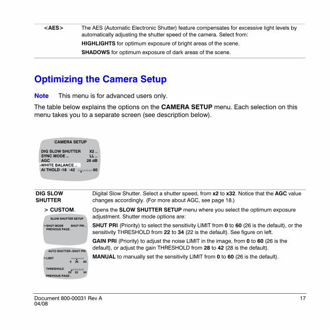
Optimizing the Camera Setup
Note This menu is for advanced users only.
The table below explains the options on the CAMERA SETUP menu. Each selection on this menu takes you to a separate screen (see description below).
<AES> The AES (Automatic Electronic Shutter) feature compensates for excessive light levels by automatically adjusting the shutter speed of the camera. Select from:
HIGHLIGHTS for optimum exposure of bright areas of the scene.
SHADOWS for optimum exposure of dark areas of the scene.
DIG SLOW SHUTTER
Digital Slow Shutter. Select a shutter speed, from x2 to x32. Notice that the AGC value changes accordingly. (For more about AGC, see page 18.)
> CUSTOM. Opens the SLOW SHUTTER SETUP menu where you select the optimum exposure adjustment. Shutter mode options are:
SHUT PRI (Priority) to select the sensitivity LIMIT from 0 to 60 (26 is the default), or the sensitivity THRESHOLD from 22 to 34 (22 is the default). See figure on left.
GAIN PRI (Priority) to adjust the noise LIMIT in the image, from 0 to 60 (26 is the default), or adjust the gain THRESHOLD from 28 to 42 (28 is the default).
MANUAL to manually set the sensitivity LIMIT from 0 to 60 (26 is the default).
>
CAMERA SETUP
DIG SLOW SHUTTER X2 ..SYNC MODE .. LL ..AGC 26 dBWHITE BALANCE ..AI THOLD -18 -42 60
!
SLOW SHUTTER SETUP
SHUT MODE SHUT PRI ..PREVIOUS PAGE .
AUTO SHUTTER--SHUT PRI
LIMIT0 26 60
THRESHOLD22 22 34
PREVIOUS PAGE .
>
>
!
!
18
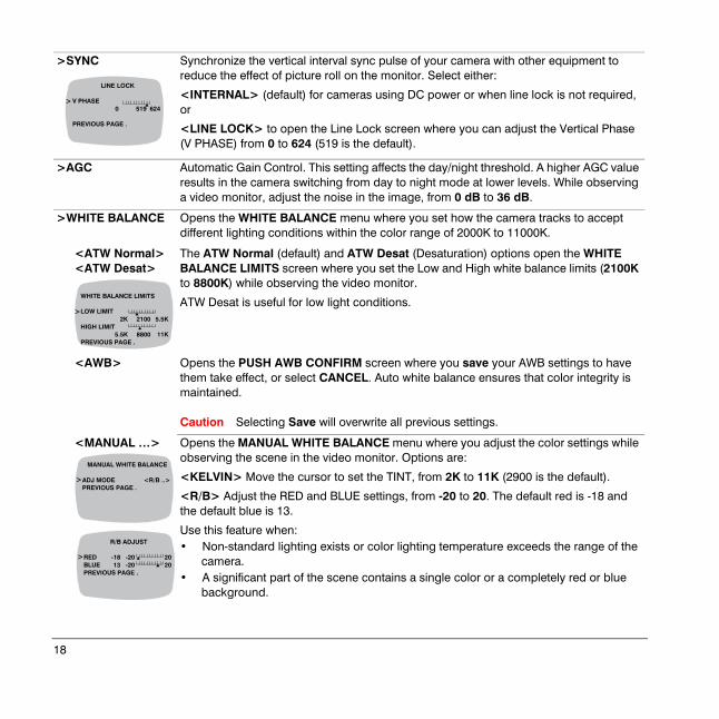
>SYNC Synchronize the vertical interval sync pulse of your camera with other equipment to reduce the effect of picture roll on the monitor. Select either:
<INTERNAL> (default) for cameras using DC power or when line lock is not required, or
<LINE LOCK> to open the Line Lock screen where you can adjust the Vertical Phase (V PHASE) from 0 to 624 (519 is the default).
>AGC Automatic Gain Control. This setting affects the day/night threshold. A higher AGC value results in the camera switching from day to night mode at lower levels. While observing a video monitor, adjust the noise in the image, from 0 dB to 36 dB.
>WHITE BALANCE Opens the WHITE BALANCE menu where you set how the camera tracks to accept different lighting conditions within the color range of 2000K to 11000K.
<ATW Normal><ATW Desat>
The ATW Normal (default) and ATW Desat (Desaturation) options open the WHITE BALANCE LIMITS screen where you set the Low and High white balance limits (2100K to 8800K) while observing the video monitor.
ATW Desat is useful for low light conditions.
<AWB> Opens the PUSH AWB CONFIRM screen where you save your AWB settings to have them take effect, or select CANCEL. Auto white balance ensures that color integrity is maintained.
Caution Selecting Save will overwrite all previous settings.
<MANUAL …> Opens the MANUAL WHITE BALANCE menu where you adjust the color settings while observing the scene in the video monitor. Options are:
<KELVIN> Move the cursor to set the TINT, from 2K to 11K (2900 is the default).
<R/B> Adjust the RED and BLUE settings, from -20 to 20. The default red is -18 and the default blue is 13.
Use this feature when:• Non-standard lighting exists or color lighting temperature exceeds the range of the
camera.• A significant part of the scene contains a single color or a completely red or blue
background.
LINE LOCK
V PHASE 0 519 624
PREVIOUS PAGE .
> !
WHITE BALANCE LIMITS
LOW LIMIT2K 2100 5.5K
HIGH LIMIT5.5K 8800 11K
PREVIOUS PAGE .
> !
!
>
MANUAL WHITE BALANCE
ADJ MODE <R/B ..>PREVIOUS PAGE .
>
R/B ADJUST
RED -18 -20 20BLUE 13 -20 20PREVIOUS PAGE .
!!
Document 800-00031 Rev A 1904/08
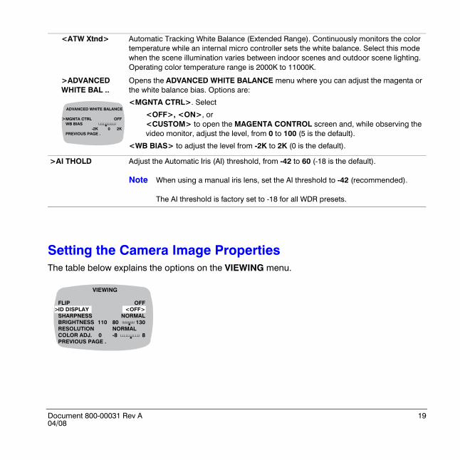
Setting the Camera Image PropertiesThe table below explains the options on the VIEWING menu.
<ATW Xtnd> Automatic Tracking White Balance (Extended Range). Continuously monitors the color temperature while an internal micro controller sets the white balance. Select this mode when the scene illumination varies between indoor scenes and outdoor scene lighting. Operating color temperature range is 2000K to 11000K.
>ADVANCED WHITE BAL ..
Opens the ADVANCED WHITE BALANCE menu where you can adjust the magenta or the white balance bias. Options are:
<MGNTA CTRL>. Select
<OFF>, <ON>, or<CUSTOM> to open the MAGENTA CONTROL screen and, while observing the video monitor, adjust the level, from 0 to 100 (5 is the default).
<WB BIAS> to adjust the level from -2K to 2K (0 is the default).
>AI THOLD Adjust the Automatic Iris (AI) threshold, from -42 to 60 (-18 is the default).
Note When using a manual iris lens, set the AI threshold to -42 (recommended).
The AI threshold is factory set to -18 for all WDR presets.
ADVANCED WHITE BALANCE
MGNTA CTRL OFFWB BIAS
-2K 0 2KPREVIOUS PAGE .
>!
VIEWING
FLIP OFFID DISPLAY <OFF>SHARPNESS NORMALBRIGHTNESS 110 80 130RESOLUTION NORMALCOLOR ADJ. 0 -8 8PREVIOUS PAGE .
>
!
!
20
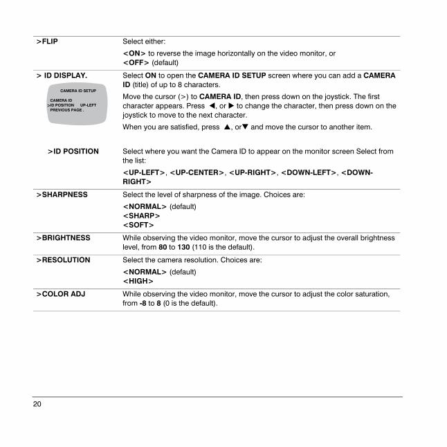
>FLIP Select either:
<ON> to reverse the image horizontally on the video monitor, or<OFF> (default)
> ID DISPLAY. Select ON to open the CAMERA ID SETUP screen where you can add a CAMERA ID (title) of up to 8 characters.
Move the cursor (>) to CAMERA ID, then press down on the joystick. The first character appears. Press #, or $ to change the character, then press down on the joystick to move to the next character.
When you are satisfied, press &, or' and move the cursor to another item.
>ID POSITION Select where you want the Camera ID to appear on the monitor screen Select from the list:
<UP-LEFT>, <UP-CENTER>, <UP-RIGHT>, <DOWN-LEFT>, <DOWN-RIGHT>
>SHARPNESS Select the level of sharpness of the image. Choices are:
<NORMAL> (default) <SHARP><SOFT>
>BRIGHTNESS While observing the video monitor, move the cursor to adjust the overall brightness level, from 80 to 130 (110 is the default).
>RESOLUTION Select the camera resolution. Choices are:
<NORMAL> (default)<HIGH>
>COLOR ADJ While observing the video monitor, move the cursor to adjust the color saturation, from -8 to 8 (0 is the default).
>
CAMERA ID SETUP
CAMERA ID ID POSITION UP-LEFTPREVIOUS PAGE .
Document 800-00031 Rev A 2104/08
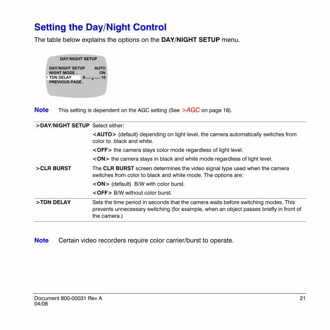
Setting the Day/Night ControlThe table below explains the options on the DAY/NIGHT SETUP menu.
Note This setting is dependent on the AGC setting (See >AGC on page 18).
Note Certain video recorders require color carrier/burst to operate.
>DAY/NIGHT SETUP Select either:
<AUTO> (default) depending on light level, the camera automatically switches from color to black and white.
<OFF> the camera stays color mode regardless of light level.
<ON> the camera stays in black and white mode regardless of light level.
>CLR BURST The CLR BURST screen determines the video signal type used when the camera switches from color to black and white mode. The options are:
<ON> (default) B/W with color burst.
<OFF> B/W without color burst.
>TDN DELAY Sets the time period in seconds that the camera waits before switching modes. This prevents unnecessary switching (for example, when an object passes briefly in front of the camera.)
!
DAY/NIGHT SETUP
DAY/NIGHT SETUP AUTONIGHT MODE .. ONTDN DELAY 0 10PREVIOUS PAGE .
>
22
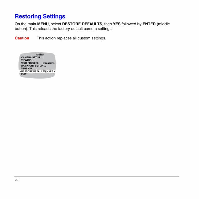
Restoring SettingsOn the main MENU, select RESTORE DEFAULTS, then YES followed by ENTER (middle button). This reloads the factory default camera settings.
Caution This action replaces all custom settings.
>
MENUCAMERA SETUP …VIEWING …WDR PRESETS <Custom>DAY/NIGHT SETUP …VERSION …RESTORE DEFAULTS <YES>EXIT
Document 800-00031 Rev A 2304/08
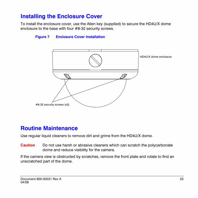
Installing the Enclosure CoverTo install the enclosure cover, use the Allen key (supplied) to secure the HD4U/X dome enclosure to the base with four #8-32 security screws.
Figure 7 Enclosure Cover Installation
Routine MaintenanceUse regular liquid cleaners to remove dirt and grime from the HD4U/X dome.
Caution Do not use harsh or abrasive cleaners which can scratch the polycarbonate dome and reduce visibility for the camera.
If the camera view is obstructed by scratches, remove the front plate and rotate to find an unscratched part of the dome.
HD4U/X dome enclosure
#8-32 security screws (x3)
24
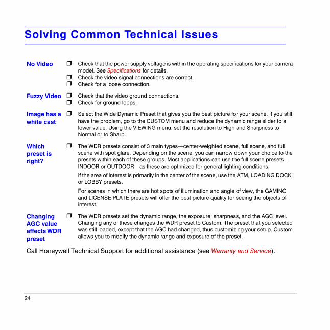
Solving Common Technical Issues
No Video ❐
❐❐
Check that the power supply voltage is within the operating specifications for your camera model. See Specifications for details.Check the video signal connections are correct.Check for a loose connection.
Fuzzy Video ❐❐
Check that the video ground connections.Check for ground loops.
Image has a white cast
❐ Select the Wide Dynamic Preset that gives you the best picture for your scene. If you still have the problem, go to the CUSTOM menu and reduce the dynamic range slider to a lower value. Using the VIEWING menu, set the resolution to High and Sharpness to Normal or to Sharp.
Which preset is right?
❐ The WDR presets consist of 3 main types—center-weighted scene, full scene, and full scene with spot glare. Depending on the scene, you can narrow down your choice to the presets within each of these groups. Most applications can use the full scene presets—INDOOR or OUTDOOR—as these are optimized for general lighting conditions.
If the area of interest is primarily in the center of the scene, use the ATM, LOADING DOCK, or LOBBY presets.
For scenes in which there are hot spots of illumination and angle of view, the GAMING and LICENSE PLATE presets will offer the best picture quality for seeing the objects of interest.
Changing AGC value affects WDR preset
❐ The WDR presets set the dynamic range, the exposure, sharpness, and the AGC level. Changing any of these changes the WDR preset to Custom. The preset that you selected was still loaded, except that the AGC had changed, thus customizing your setup. Custom allows you to modify the dynamic range and exposure of the preset.
Call Honeywell Technical Support for additional assistance (see Warranty and Service).
Document 800-00031 Rev A 2504/08
Warranty and Service
Subject to the terms and conditions listed on the Product warranty, during the warranty period Honeywell will repair or replace, at its sole option, free of charge, any defective products returned prepaid.
In the event you have a problem with any Honeywell product, please call Customer Service at 1.800.796.CCTV for assistance or to request a Return Merchandise Authorization (RMA) number.
Be sure to have the model number, serial number, and the nature of the problem available for the technical service representative.
Prior authorization must be obtained for all returns, exchanges, or credits. Items shipped to Honeywell without a clearly identified Return Merchandise Authorization (RMA) number may be refused.
26
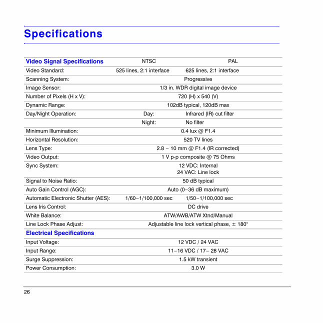
Specifications
Video Signal Specifications NTSC PAL
Video Standard: 525 lines, 2:1 interface 625 lines, 2:1 interface
Scanning System: Progressive
Image Sensor: 1/3 in. WDR digital image device
Number of Pixels (H x V): 720 (H) x 540 (V)
Dynamic Range: 102dB typical, 120dB max
Day/Night Operation: Day: Infrared (IR) cut filter
Night: No filter
Minimum Illumination: 0.4 lux @ F1.4
Horizontal Resolution: 520 TV lines
Lens Type: 2.8 – 10 mm @ F1.4 (IR corrected)
Video Output: 1 V p-p composite @ 75 Ohms
Sync System: 12 VDC: Internal24 VAC: Line lock
Signal to Noise Ratio: 50 dB typical
Auto Gain Control (AGC): Auto (0–36 dB maximum)
Automatic Electronic Shutter (AES): 1/60–1/100,000 sec 1/50–1/100,000 sec
Lens Iris Control: DC drive
White Balance: ATW/AWB/ATW Xtnd/Manual
Line Lock Phase Adjust: Adjustable line lock vertical phase, ± 180°
Electrical SpecificationsInput Voltage: 12 VDC / 24 VAC
Input Range: 11–16 VDC / 17– 28 VAC
Surge Suppression: 1.5 kW transient
Power Consumption: 3.0 W
Document 800-00031 Rev A 2704/08
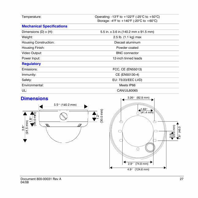
Temperature: Operating: -13°F to +122°F (-25°C to +50°C)Storage: -4°F to +140°F (-20°C to +60°C)
Mechanical SpecificationsDimensions (D) x (H): 5.5 in. x 3.6 in.(140.2 mm x 91.5 mm)
Weight: 2.5 lb. (1.1 kg) max
Housing Construction: Diecast aluminum
Housing Finish: Powder coated
Video Output: BNC connector
Power Input: 12-inch tinned leads
RegulatoryEmissions: FCC, CE (EN55013)
Immunity: CE (EN50130-4)
Safety: EU: 73/23/EEC LVD)
Environmental: Meets IP66
UL: CAN/UL60065
Dimensions
1.8”
(46
.0
0.9”
(2
3.0
mm
)
4.9” (124.6 mm)
2.9” (74.8 mm)
3.26” (82.8 mm)
1.63” (41.4 mm)
28
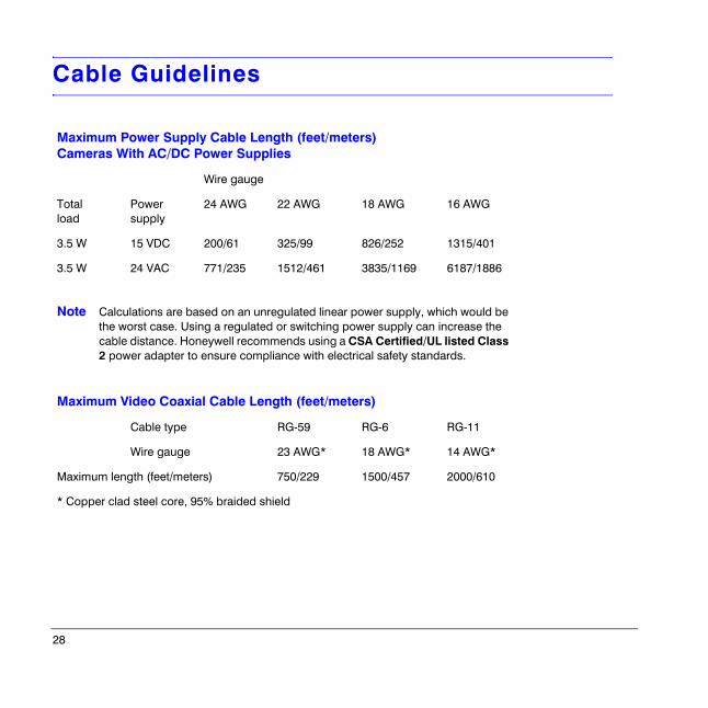
Cable Guidelines
Maximum Power Supply Cable Length (feet/meters)Cameras With AC/DC Power Supplies
Wire gauge
Total load
Power supply
24 AWG 22 AWG 18 AWG 16 AWG
3.5 W 15 VDC 200/61 325/99 826/252 1315/401
3.5 W 24 VAC 771/235 1512/461 3835/1169 6187/1886
Note Calculations are based on an unregulated linear power supply, which would be the worst case. Using a regulated or switching power supply can increase the cable distance. Honeywell recommends using a CSA Certified/UL listed Class 2 power adapter to ensure compliance with electrical safety standards.
Maximum Video Coaxial Cable Length (feet/meters)
Cable type RG-59 RG-6 RG-11
Wire gauge 23 AWG* 18 AWG* 14 AWG*
Maximum length (feet/meters) 750/229 1500/457 2000/610
* Copper clad steel core, 95% braided shield
Document 800-00031 Rev A 2904/08
HD4U Mounting Template

30
Document 800-00031 Rev A 3104/08
© 2008 Honeywell International Inc. All rights reserved. No part of this publication may be reproduced by any means without written permission from Honeywell Video Systems. The information in this publication is believed to be accurate in all respects. However, Honeywell Video Systems cannot assume responsibility for any consequences resulting from the use thereof. The information contained herein is subject to change without notice. Revisions or new editions to this publication may be issued to incorporate such changes.
Honeywell Video Systems (Head Office)2700 Blankenbaker Pkwy, Suite 150Louisville, KY 40299, USAwww.honeywellvideo.com℡ +1.800.796.2288
Honeywell Security Australia Pty Ltd.Unit 5, Riverside Centre, 24-28 River Road WestParramatta, NSW 2150, Australiawww.honeywellwsecurity.com/au℡ +61.2.8837.9300
Honeywell Security Asia Pacific33/F Tower A, City Center, 100 Zun Yi RoadShanghai 200051, Chinawww.asia.security.honeywell.com℡ +86 21.2527.4568
Honeywell Security AsiaFlat A, 16/F, CDW Building, 388 Castle Peak RoadTsuen Wan, N.T., Hong Kongwww.asia.security.honeywell.com℡ +852.2405.2323
Honeywell Security FranceParc Gutenberg, 8, Voie La Cardon91120, Palaiseau, Francewww.honeywell.com/security/fr℡ +33.01.64.53.80.40
Honeywell Security Italia SpAVia della Resistenza 53/5920090 BuccinascoMilan, Italywww.honeywell.com/security/it℡ ++39.02.48880551
Honeywell Security EspañaMijancas 1. 3a PlantaP. Ind. Las Mercedes28022 Madrid, Spainwww.security.honeywell.com/es℡ +34.902.667.800
Honeywell Video Systems Northern EuropeNetwerk 1211446 WV Purmerend, The Netherlandswww.honeywell.com/security/nl℡ +31.299.410.200
Honeywell Systems GroupAston Fields Road, Whitehouse Ind EstRuncorn, Cheshire, WA7 3DL, UKwww.honeywell.com/security/uk℡ +44 (0)1928 756999
Honeywell Security South AfricaUnit 6 Galaxy Park, 17 Galaxy AvenueLinbro Park, P.O. Box 599042100 Kengray, Johannesburg, South Africawww.honeywell.co.za℡ +27.11.574.2500
Honeywell Security DeutschlandJohannes-Mauthe-Straße 14D-72458 Albstadt, Germanywww.honeywell.com/security/de℡ +49.74 31.8 01.0
Honeywell Security PolandChmielewskiego 22a, 70-028Szczecin, Polskawww.ultrak.pl℡ +48.91.485.40.60
Honeywell Security Czech RepublicHavránkova 33, BrnoDolní Heršpice, 619 00, Czech Republicwww.olympo.cz℡ +420.543.558.111
Honeywell Security Slovakia RepublicVajnorská 142, 83104 BratislavaSlovakiawww.olympo.sk℡ +421.2.444.54.660
www.honeywellvideo.com+1.800.796.CCTV (North America only)
Document 800-00031 – Rev A – 04/08