DATE: ADVISORY and 2 CIRCULAR
36
AC NO: 15ot522o-1o DATE: 26 May n Reprinted 4/1176 Incorporates Changes 1 and 2 ADVISORY CIRCULAR GUIDE SPECIFICATION FOR WATER/FOAM TYPE AIRCRAFT FIRE AND RESCUE TRUCKS DEPARTMENT OF TRANSPORTATION FEDERAL AVIATION ADMINISTRATION Initiated by: AS-570
Transcript of DATE: ADVISORY and 2 CIRCULAR
AC NO: 15ot522o-1o
DATE: 26 May n Reprinted 4/1176 Incorporates Changes 1 and 2
ADVISORY CIRCULAR
GUIDE SPECIFICATION FOR WATER/FOAM TYPE AIRCRAFT FIRE AND RESCUE TRUCKS
DEPARTMENT OF TRANSPORTATION FEDERAL AVIATION ADMINISTRATION
Initiated by: AS-570

AC NO: 150/5220-lo
DATE: 26 May n
ADVISORY CIRCULAR
DEPARTMENT OF TRANSPORTATION FEDERAL AVIATION ADMINISTRATION
GUIDE SPECIFICATION FOR WATER/FOAM TYPESUBJECT: AIRCRAFT FIRE AND RESCUE TRUCKS 1. PURPOSE. This guide specification was developed by the Federal Aviation
Administration (FAA) to assist airport management in the development of local procurement specifications. It is not addressed to any regulatory requirements of FAA but is promulgated for general use. The word "shall" is not to be construed as a mandatory requirement of FAA. It is specifically included so that portions of this guide specification may be copied verbatim by local specification writers.
2. CANCELLATION. The technical material contained in this advisory circular has been extracted from the advisory circulars listed below. The following advisory circulars are cancelled:
a. AC 150/5220-2, Guide Specification for 1,800-Gallon Aircraft Fire and Rescue Truck.
b. AC 150/5220-3, Guide Specification for 1,000-Gallon Aircraft Fire and Rescue Truck.
c. AC 150/5220-5, Guide Specification for a Combination Foam and Dry Chemical Aircraft Fire and Rescue Truck.
d. AC 150/5220-7, Guide Specification for 2,500-Gallon Aircraft Fire and Rescue Truck.
3. HOW TO OBTAIN THIS PUBLICATION. Additional copies of this publication, AC 150/5220-10, Guide Specification for Water/Foam Type Aircraft Fire and Rescue Trucks, may be obtained from the Department of Transportation, Distribution Unit, TAD-484.3, Washington, D.c. 20590.
CHESTER G. BOWERS Director, Airports Service
Initiated by: AS-570

26 May 72
CHAPTER 1.
1. 2. 3.
CHAPTER 2.
SEenON 4. 5. 6. 7. 8. 9.
SECTION 10. ll. 12.
SEenON 13. 14. 15. 16. 17. 18.
SEenON 19. 20. 21. 22, 23. 24. 25.
SECTION 26. 27. 28. 29, 30, 31.
TABLE OF CONTENTS
INTRODUcnON
Scope General Applicable Documents and Source of Supply
REQUIREMENTS
1. GENERAL VEHIU.E DESCRIPTION Classes Vehicles Materials Design Construction Performance
2. DETAILS OF CHASSIS DESIGN AND COMPONENTS Vehicle Chassis Vehicle Dimensions and Clearances Frame
3. DETAILS OF ENGINE AND COMPONENTS Engine Cooling System Fuel System Governor Lubricating Systems Exhaust System and Muffler
4. DETAILS OF DRIVELINE COMPONENTS Transmission Transfer Case Axles Braking System Steering Mechanism Suspension System Wheel and Tire Assembly
5. DETAILS OF CAB General Capacity Windshield Mirrors Instruments Heater/Defroster
AC 150/5220·10
Page No.
1
1 1 2
3
3 3 3 3 3 5 5
6 6 6 7
8 8 8 8 9 9 9
9 9 9
10 10 11 11 11
11 11 12 12 12 12 12
Page i

Page No,
SECTION 6. DETAILS OF ELECTRICAL SYSTEM AND DEVICES 12 32. General 12 33, Power Supply 13 34. Batteries 13 35, Starting Device 13 36, Ignition System for Gasoline Engines 14 37. Battery Charging Connection 14 38, Lighting System 14
SECTION 7. DETAILS OF SHEET METAL CXlMPONENTS 15 39, Body 15 40, Steps and Running Boards 15 41. Walkway 15 42. Handrails 15 43. Compartments 15
SECTION 8, DETAILS OF FIRE FIGHTING EQUIPMENT AND COMPONENTS 16
44. Pump(s) Drive 16 45. Pump( s) 16 46. Pump Connections 16 47. Heat Exchanger 17 48. Pump and Engine Controls 17 49. Water Tank 18 so. Tank Filler Connection 19 51. Foam Proportioning System 19 52. Foam Concentrate Storage 20 53. TUrret 21 54. Handline Reels and Nozzles 22 55. Ground-Sweep Nozzle(s) 23 56. Dry Chemical System 23 57. Auxiliary Equipment 23
SECTION 9, MISCELLANEOUS DETAILS 24 58. Radio Interference Suppression 24 59. Treating and Painting 24 60. Tools 24 61. Nameplates and Instruction Plates 24 62. Lubrication and Hydraulic Fluids 25 63. Technical Publications 25
Page ii

' 26 May 72 AC 150/5220-10
Page No.
CHAPTER 3. QUALITY ASSURANCE PROVISION 27
64. General 27 65. Inspectioas and Tests Procedures 27 66. Preparation for Delivery 28 67. Warranty 29 68. Production Options 29
Page iii

26 May 72 AC 150/5220-10
CHAPTER 1. INTRODUCTION
1. SCOPE. This specification covers a family of all-wheel drive, gasoline or diesel engine-driven, heavy-duty, high-mobility aircraft fire and rescue trucks having a mechanical foam system for use in dispensing foam as the primary extinguishing agent.
2. GENERAL.
a. These vehicles are primarily intended for use in rescuing trapped personnel and combating aircraft fires resulting from an aircraft ground emergency. These vehicles·may also be used for other fire protection assignments necessary in airport operations.
b. This guide specification describes vehicles possessing the minimum performance capabilities recommended for an acceptable aircraft fire and rescue truck. These vehicles are capable of carrying the quantities of water and foam concentrate liquid specified for each class truck listed in paragraph 4 and the necessary auxiliary equipment to combat either aircraft or structural fires. The pumps shall be capable of discharging water and foam liquid as specified for each class vehicle when drafting from the vehicle tanks or from an outside source and when pumping from a hydrant in the quantity and rate necessary to meet limited structural fire fighting requirements.
c. This specification may be modified, as desired, to require additional vehicle capabilities, trim, or accessories. So that the purchaser may select certain components with characteristics which better meet individual requirements, production options have been included in the specification. Accordingly, it will be necessary to specify which of the production options specified in paragraph 68 are desired.
d. In Publication No. 414, "Aircraft Rescue and Fire Fighting Vehicles," the National Fire Protection Association describes the vehicle characteristics and components which, when properly selected and assembled in a procurement document, will permit purchase of aircraft rescue and fire fighting trucks that should satisfy predetermined requirements. The agency has developed this guide specification describing a complete line of water/foam trucks, which, when used in conjunction with other types of fire fighting apparatus, will provide the fire protection capabilities recommended for airports. Trucks built to this specification will permit an orderly progression, with a minimum economic burden, in providing a reasonable degree of fire and rescue protection as aeronautical operations increase at an airport.
Chap 1 Par 1 Page 1

AC 150/5220-10 26 May 72
3. APPLICABLE DOCUMENTS AND SOURCE OF SUPPLY. Only the applicable portions of the documents referenced below form a part of this specification. These documents may be obtained from the addresses listed below:
a. Federal Standard No. 595, Color - Specification Activity, Printed Materials Supply Division, Building 197, Naval Weapons Plant, Washington, D.C. 20407.
b. Motor Carrier Safety Regulations - Federal Highway Administration, Washington, D.c. 20590.
c. Tire and Rim Association Yearbook- Tire and Rim Association, Inc., 2001 First National Tower, Akron, Ohio 44308.
d. Standard for Mill Products - The Aluminum Association, 420 Lexington Avenue, New York, New York 10017.
Chap 1 Page 2 Par 3
26 May 72 AC 150/5220-10
CHAPTER 2. REQUIREMENTS
SECTION 1. GENERAL VEHICLE DESCRIPTION
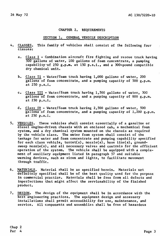
4. CLASSES. This family of vehicles shall consist of the following four classes:
a. Class I - Combination aircraft fire fighting and rescue truck having 500 gallons of water, 100 gallons of foam concentrate, a pumping capability·of 250 g.p.m. at 150 p.s.i., and a 300-pound compatible dry chemical unit.
b. Class II - Water/foam truck having 1,000 gallons of water, 200 gallons of foam concentrate, and a pumping capacity of 500 g.p.m. at 250 p.s.i.
c. Class III - Water/foam truck having 1,500 gallons of water, 300 gallons of foam concentrate, and a pumping capacity of 800 g.p.m. at 250 p.s.i.
d. Class IV - Water/foam truck having 2,500 gallons of water, 500 gallons of foam concentrate, and a pumping capacity of 1,200 g.p.m. at 250 p.s.i.
5. VEHICLES. These vehicles shall consist essentially of a gasoline or diesel engine-driven chassis with an enclosed cab, a mechanical foam system, and a dry chemical system mounted on the chassis as required by the vehicle class. The water foam system shall consist of the tankage for water and foam concentrate and pumping capability specified for each class vehicle, turret(s), nozzle(s), hose line(s), groundsweep nozzle(s), and all necessary valves and controls for the efficient operation of the system. The vehicle shall be equipped with a complement of auxiliary equipment listed in paragraph 57 and suitable warning devices, such as siren and lights, to facilitate movement through traffic.
6. MATERIALS. Material shall be as specified herein. Materials not definitely specified shall be of the best quality used for the purpose in commercial practice. Materials shall be free from all defects and imperfections that might affect the serviceability of the finished product.
7. DESIGN. The design of the equipment shall be in accordance with the best engineering practices. The equipment design and accessory installations shall permit accessibility for use, maintenance, and service. All components and assemblies shall be free of hazardous
Chap 2 Par 4 Page 3

AC 150/5220-10 CHG 1 4 Dec 72
protrusions, sharp edges, cracks, or other elements which might cause injury to personnel or equipment, All oil, hydraulic, and air tubing lines and electrical wiring shall be located in protective positions, properly clipped to the frame or body structure, and shall have protective loom or grommets at each point where they pass through structural members, except where a through-frame connector is necessary.
a. Gross Vehicle Weight, The gross vehicle weight (GVW), including weight of the complete chassis and cab with all attachments, accessories, and equipment required by this specification; body; rated payload; and full complement of fuel, lubricants, coolant, and operating personnel (525 pounds), shall be as shown for each class vehicle shown below. The gross vehicle weight rating shall not exceed the sum of the axle manufacturer's certified load ratings for the axles used, The manufacturer's advertised gross vehicle weight rating shall not be arbitrarily raised to meet the requirements of this specification,
GROSS WEIGHT RATINGS
Minimum GVW Maximum GVW ... _____
Class I 20,000
Class II 25,000 35,000
Class III 38,000 45,000
Class IV 55,000 65,000
* b, Weight Distribution. The center of gravity shall be kept as low as possible under all conditions of loading, The vehicle shall be capable of resting on a side slope equivalent to a 30 percent grade without danger of overturning. The weight distribution for particular chassis designs shall be selected from the following:
(l) Class I
(a) Chassis 4 wheel - 4x4, dual rear tires, 33 percent front axle, 67 percent rear axle,
(b) Chassis 4 wheel - 4x4, single tires, 50 percent front axle, 50 percent rear axle.
Chap 2 Page 4 Par 7

4 Dec 72 AC 150/5220-10 CHG 1
(2) Class II
(a) Chassis 4 wheel, 4-wheel drive (4x4), single tires, 50 percent front axle, 50 percent rear axle.
(b) Chassis 6 wheel, 6-wheel drive (6x6), single tires, 33 percent front axle, 67 percent rear bogie.
(c) Chassis 4 wheel, 4-wheel drive (4x4), dual rear tires, 33 percent front axle, 67 percent rear axle.
(d) Chassis 6 wheel, 6-wheel drive (6x6), dual rear tires, 20 percent front axle, 80 percent rear bogie.
( 3) Class III
(a) Chassis 4 wheel, 4-wheel drive (4x4), single tires, 50 percent front axle, 50 percent rear axle.
(b) Chassis 6 wheel, 6-wheel drive (6x6), single tires, 33 percent on front axle, 67 percent on rear bogie.
(c) Chassis 4 wheel, 4-wheel drive (4x4), dual rear tires, 33 percent front axle, 67 percent rear axle.
(d) Chassis 6 wheel, 6-wheel drive (6x6), dual rear tires, 20 percent front axle, 80 percent rear bogie.
(4) Class IV
(a) Chassis 4 wheel, 4-wheel drive (4x4), single tires, 50 percent front axle, 50 percent rear axle.
(b) Chassis 6 wheel, 6-wheel drive (6x6), single tires, 33 percent front axle, 67 percent rear bogie.
(c) Chassis 8 wheel, 8-wheel drive (8x8), single tires, 50 percent front bogie, 50 percent rear bogie. *
Chap 2 Par 7 Page 4-1

26 May 72 AC 150/5220-10
8. CONSTRUCTION. The vehicle shall be constructed so that no part can work loose in service. The vehicle shall be built to withstand the strains, jars, vibrations, and other conditions incident to service intended. Design of the vehicle shall produce the necessary clearances to permit the satisfactory use of tire chains on all wheels when traversing adverse terrain.
9. PERFORMANCE. The vehicle, fully equipped and provided with fuel, lubricants, operating personnel, and extinguishing agents, shall be designed to possess capabilities for:
a. Accelerating from a standing start to a speed of 50 m.p.h. on a dry, level pavement, free from loose materials, having a friction coefficient of 0.6 in accordance with the following:
Seconds
Class I 40
Class II 60
Class III 60
Class IV 60
b. Maintaining a cruising speed of not less than 50 m.p.h. when operating on dry, paved roadway having grades not in excess of 1.5 percent.
c. Maintaining a speed on dry, paved roadway of not more than 2.5 m.p.h. at an engine speed that does not result in rough, irregular operation.
d. Ascending a dry, paved incline having an 8 percent grade for a distance of one-quarter mile at a speed of not less than 20 m.p.h.
e. Ascending a dry, hard surface incline having a not less than 2.5 m.p.h.
50 percent grade at
f. Operating on side slopes, right or left, up to 20 percent and longitudinal slopes up or down to 50 percent.
on
g. Operating continuously for 25 miles at speeds up to 15 m.p.h. over all types of terrain encountered in cross-country travel, including surfaced and unsurfaced roads, and on grades normally encountered in this type of operation. During this performance requirement, the vehicle shall be operated in all-wheel drive. At least 5 miles of this operation shall be cross-country travel.
Chap 2 Par 8 Page 5

AC 150/5220-10 26 May 72
h. Bringing the fully loaded vehicle, using the serv~ce brakes, to 5 complete successive stops within 30 feet from a speed of 20 m.p.h. on dry, hard pavement free from loose materials and controlling the vehicle on all grades encountered in cross-country operation,
i, Bringing the fully loaded vehicle, using the hand brake, to a complete stop on a level road and holding the vehicle on the grades encountered (up to 30 percent) in ~ross-country operation,
j. Negotiating muddy and sandy terrain as usually required of wheeled vehicles designed for off-highway use.
k. Operating over rough roads and adverse terrain at speeds up to 15 m.p.h. without exposing operating personnel to injury or causing damage to the vehicle or fire fighting equipment.
l. Exerting a ground pressure on any wheel of not greater than 45 p.s.i. based on the gross contact area of the tires at zero penetration.
SECTION 2. DETAILS OF CHASSIS DESIGN AND COMPONENTS
10. VEHICLE CHASSIS. The vehicle chassis, complete with cab, shall be of the 4x4, 6x6, or 8x8 type front-wheel steering, gasoline or diesel engine-driven, Parts and accessories necessary for the safe operation of the vehicle shall be provided as required by and shall conform to applicable provisions of the Federal Highway Administration's (FHWA) Motor Carrier Safety Regulations, Part 293. The vehicle and all components shall be new and unused.
ll. VEHICLE DIMENSIONS AND CLEARANCES. The vehicle shall conform to the following dimensions and clearances:
a. The overall height shall not exceed:
(1) 130 inches for Class I vehicles.
(2) 144 inches for Class II, III, and IV vehicles
b, The overall length shall be held to a minimum but shall not exceed:
( 1 ) 260 inches for Class I vehicles.
(2) 300 inches for Class 11 vehi c1es.
(3) 360 inches for Class 111 vehicles.
(4) 400 inches for Class IV vehicles.
Chap 2 Page 6 Par 9

26 May 72 AC 150/5220-10
c, The basic vehicle width shall not exceed 100 inches, equipment may extend width to 104 inches,
Removable
d. The wheel base shall be held to a minimum but shall not exceed:
(1) 154 inches for Class I vehicles,
(2) 195 inches for Class II vehicles,
(3) 200 inches for Class III vehicles,
(4) 210 inches for Class IV vehicles,
e, The angle of approach shall not be less than 30°,
f. The angle of departure shall not be less than 30°,
g. The under chassis clearance shall not be less than:
(1) 12 inches for Class I vehicles,
(2) 16 inches for Class II vehicles.
(3) 18 inches for Class III and IV vehicles,
h. The under axle clearance shall not be less than 12 inches,
i. The diameter of the outside tire centerline track shgreater than 3 times the overall length of the vehicmaximum cramping angle shall not be less than 28°,
all not le, and
be the
12, FRAME, The chassis frame shall .be of riveted, bolted, or welded construction and shall be provided with adequate cross members, exclusive of engine supports, so designed and constructed as to support gross weight of the body and load, powerplant, pump filled water tank, and all other equipment under operating conditions specified herein. No alterations shall be made to the frame which will reduce its designated strength. If frameless integral body construction is used, the manufacturer shall certify that the design meets the above requirements, Two towing hooks or eyes shall be attached directly to the chassis frame at the front and one or two on the rear of the vehicle.
Chap 2 Par 11 Page 7

AC 150/5220-10 CHG 2 8/22/73
SECTION 3, DETAILS OF ENGINE AND COMPONENTS
13, ENGINE, The vehicle engine(s) shall be of the internal combustion, 4-stroke cycle or 2-stroke cycle, gasoline or diesel type, having not less than 6 cylinders. The vehicle engine(s) shall develop the torque and horsepower to provide the speed and gradability of the vehicle as specified in paragraphs 9a through 9g without the engine exceeding a "no load" governed speed at the peak of a certified gross brake horsepower (b,hp) curve. The engine(s) shall operate satisfactorily and shall be capable of demonstrating the performance characteristics specified herein with fuel conforming to regular commercial grade.
14,* ENGINE COOLING SYSTEM AND TRUCK WINTERIZATION.
a, Provide an engine cooling system of the circulating li2uid type to maintain a coolant temperature of not more than 210 F. or less than 140°F. when operated in ambient temperatures of -20°F, {In areas experiencing temperatures below -20°F,, and where it is common industry practice to do so, it is considered advisable to design for winterization down to -40°F., for example, to include the cooling system devices, oil pan heaters, and lubricating oil heaters.)
b. Provide a bypass to permit coolant circulation in the engine block, with thermostat closed, until normal operating temperature is reached. A 160°F. thermostat shall be provided with the cooling system being designed to witstand an inten1al pressure of 7 p.s.i. Install drain cocks at the low point of the cooling system and at such other points as may be necessary to drain the system completel~ A coolant temperature gage shall be provided on the cab instrument panel.
c. Winterization of the fire fighting system on a truck shall be based on meeting the same (low·er) temperature requirements as .the engine system. This includes heating devices for the extinguishant solution tanks, piping, pumps, etc., and insulating compartments housing these system units so that the trucks can continue in operational status during prolonged periods of freezing temperatures described in paragraph a. above. *
15. FUEL SYSTEM. The engine(s) fuel system for the truck engine shall be so installed as to preclude the possibility of vapor lock. It shall include carburetor(s) or injector(s), manual or automatic choke, fuel pumps, fuel strainers, oil bath air cleaners, all necessary piping,
Chap 2 Page 8 Par 13
8/22/73 AC 150/5220-10 CHG 2
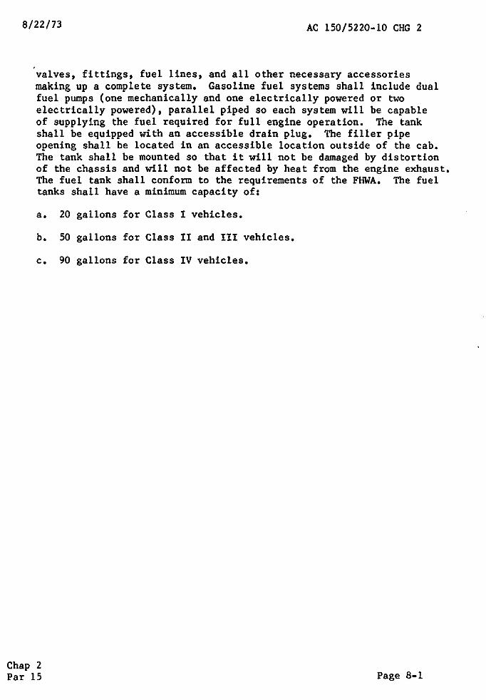
'valves, fittings, fuel lines, and all other necessary accessories making up a complete system, Gasoline fuel systems shall include dual fuel pumps (one mechanically and one electrically powered or two electrically powered), parallel piped so each system will be capable of supplying the fuel required for full engine operation. The tank shall be equipped with an accessible drain plug, The filler pipe opening shall be located in an accessible location outside of the cab, The tank shall be mounted so that it will not be damaged by distortion of the chassis and will not be affected by heat from the engine exhaust, The fuel tank shall conform to the requirements of the FHWA, The fuel tanks shall have a minimum capacity of:
a, 20 gallons for Class I vehicles.
b, 50 gallons for Class II and III vehicles,
c, 90 gallons for Class IV vehicles.
Chap 2 Par 15 Page 8-1
AC 150/5220-1026 May 72
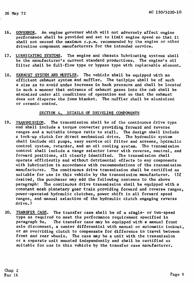
16. GOVERNOR. An engine governor which will not adversely affect engine performance shall be provided and set to limit engine speed so that it shall not exceed the maximum r.p.m. recommended by the engine or other driveline component manufacturers for the intended service.
17. LUBRICATING SYSTEMS. The engine and chassis lubricating systems shall be the manufacturer's current standard productions. The engine's oil filter shall be full-flow type or bypass type with replaceable element.
18. EXHAUST SYSTEM AND MUFFLER. The vehicle shall be equipped with an efficient exhaust system and muffler. The tailpipe shall be of such a size as to avoid undue increase in back pressure and shall be located in such a manner that entrance of exhaust gases into the cab shall be minimized under all conditions of operation and so that the exhaust does not disperse the foam blanket. The muffler shall be aluminized or ceramic coated.
SECTION 4. DETAILS OF DRIVELINE COMPONENTS
19. TRANSMISSION. The transmission shall be of the continuous drive type and shall include a torque converter providing forward and reverse ranges and a suitable torque ratio to stall. The design shall include a lock-up clutch for direct mechanical drive. The hydraulic system shall include oil pumps, easy service oil filter and screens, hydraulic control system, retarder, and an oil cooling system. The transmission control shall include a range selector lever with reverse, neutral, and forward positions, all clearly identified. The transmission shall operate efficiently and without detrimental effects to any components with lubrication in accordance with recommendations of the transmission manufacturer. The continuous drive transmission shall be certified as suitable for use in this vehicle by the transmission manufacturer. (If desired, the purchaser may add the following sentence to the above paragraph: The continuous drive transmission shall be equipped with a constant mesh planetary gear train providing forward and reverse ranges, power-operated hydraulic clutches, power shift in all forward speed ranges, and manual selection of the hydraulic clutch engaging reverse drive.)
20. TRANSFER CASE. The transfer case shall be of a single- or two-speed type as required to meet the performance requirement specified in paragraph 9e. The transfer case may be equipped with a manual front axle disconnect, a center differential with manual or automatic lockout, or an overriding clutch to compensate for difference in travel between front and rear wheels. The case may be a unit with the transmission or a separate unit mounted independently and shall be certified as suitable for use in this vehicle by the transfer case manufacturer.
Chap 2 Par 16 Page 9

AC 150/5220-10 26 May 72
21. AXLES. The axles furnished shall be certified as being suitable for use in this vehicle by the axle manufacturer. Axle manufacturer's published rating shall not be raised to conform to the requirements of this specification and shall be at least equal to the load imposed at ground level when the vehicle is loaded to its rated gross vehicle weight; each axle to be provided with no spin or other retarding type differential lock to assure a torque transfer to each wheel retaining traction. If manual lockout is required, the lockout control shall be located in the vehicle cab. The front and rear bogies on all 6x6 and BxB vehicles shall be of the 4-wheel type complete with axles, springs, torque rods, and all other necessary parts. The bogies shall be provided with means permitting differential action between the two axles.
22. BRAKING SYSTEM. A braking system which meets the FHWA requirements for similar type vehicles shall be furnished complete with all necessary equipment to safely control the fully equipped and loaded or unloaded vehicle under all operating conditions. The brake mechanism shall be readily accessible to external adjustment.
a. Service brakes for Class 1 vehicles shall be of the hydraulic type provided on all wheels and equipped with power assistance and shall be capable of meeting the brake tests specified in paragraph 65d.
b. Service brakes for Class 1I, III, and IV vehicles shall be of the full-air or air-over-hydraulic type provided with an air compressor designed to include an unloader head to prevent a buildup of excessive air pressure in the system when the compressor is not in operation. It shall be engine-driven having a capacity sufficient for the intended service but of not less than 12 cubic feet per minute capacity. The compressor intake shall be provided with a suitable air cleaner. An adequate air storage reservoir shall be furnished and provided with a low pressure indicator of the buzzer type. The system shall be of the quick pressure buildup type with the air compressor connected to a small reservoir having a minimum 800 cubic-inch capacity which is pressure relieved into the larger reservoir(s) when the minimum pressure is reached for maximum operation of the brake system. The total cubic storage capacity of the reservoir shall not be less than 13 times the volume of the brake actuating chambers or 2,000 cubic inches, whichever is greater.
c. A parking brake operated by a control readily accessible to the driver shall be provided. The parking brake shall be separate from the service brakes.
Chap 2 Page 10 Par 21

26 May 72 AC 150/5220-10
23. STEERING MECHANISM. The vehicle chassis shall be equipped with a standard hydraulic power assist steering mechanism operable from the driver's seat. Means shall be provided for rapid and easy adjustment of lost motion in the steering gear. The steering mechanism shall be capable of easily controlling the direction of the fully loaded vehicle under all operating conditions.
24. SUSPENSION SYSTEM. Vehicles shall be equipped with manufacturer's current suspension system having a rated capacity at least equal to the imposed load, measured at ground level, with the vehicle loaded to its rated GVW. When spring capacity is rated at the spring pads, unsprung weight shall be deducted. Ratings shall not be raised to conform to the requirements of this specification, and suspension shall evidence no overload or permanent set.
25. WHEEL AND TIRE ASSEMBLY. The wheels shall be either disc or spoke type as currently furnished by the vehicle manufacturer. Rim contours and size shall conform to the current practices of the Tire and Rim Association, Inc., as recommended for use in the design of new vehicles.
a. Each tire, at 45 p,s.i. inflation pressure, shall have a rated carrying capacity at least equal to the gross load normally imposed on it by the evenly and fully loaded vehicle. The load rating capacity of the tires should be in conformance with practices of the Tire and Rim Association, Inc. Tires, including spare, shall be interchangeable and of the same size. An aggressive tire tread of the military or lug type with center rib is recommended for general service. Tires and tubes shall meet the first line commercial grade requirements.
b. A spare wheel or rim with tire and tube included shall be provided; however, provisions shall not be made to mount the wheel or rim on the vehicle.
SECTION 5. DETAILS OF CAB
26. GENERAL. An all metal or fiberglass constructed cab of the conventional or forward design shall be furnished. The roof and floor of the cab shall be insulated. The engine and driver's compartment shall be separated by insulation. The cab roof around turret(s) and all working areas and steps on cab and body are to be 4-way safety tread plate pattern. The cab roof is to be provided with suitable safety railings and with gutters to drain nozzle drippings.
Chap 2 Far 23 Page 11

AC 150/5220-10 26 May 72
27. CAPACITY. Seating shall be provided for at least three men including the driver. The driver's seat shall be easily adjustable up and down, fore and aft, a minimum of 3 inches. Seats shall be fully upholstered with a good quality plastic type upholstery over foam rubber cushions. Approved, properly installed seat belts, one for the driver and each passenger, shall be provided.
28. WINDSHIELD. All glass shall be of the laminated safety plate type, free of all imperfections which would affect visibility. The windshield shall be equipped with dual, 2-speed electric or air wipers which shall sweep a clear view for both the driver and the passengers. A windshield washer of the 1-gallon size shall be provided and properly installed. Two sunvisors shall be provided.
29. MIRRORS. Two outside rear view mirrors, of the extension arm "westcoast" type having an area of not less than 60 square inches, shall be provided; one mounted on either side of the cab.
30. INSTRUMENTS. The cab instrument panel or board shall include, but not be limited to: panel lights; speedometer with recording odometer; engine heat indicator; carburetor choke(s) when required; ammeter; lighting switches; fuel, oil pressure, and air pressure gauges; ignition swi tche( s); and a tachometer( s) having engine( s) hour meter or engine( s) revolution counter.
31. HEATER/DEFROSTER. A cab heater and windshield defroster shall be provided which will be capable of maintaining a cab temperature of 50°F. at ambient temperatures of -20°F.
SECI'ION 6. DETAILS OF ELECTRICAL SYSTEM AND DEVICES
32. GENERAL. The electrical system and devices shall be installed in accordance with the best modern practices for the type of service required--generator, alternator, starting device, ignition distributors, ignition coils and magneto, shall be of t~aterproof type, accessibly mounted and protected against excessive heat. All electrical circuit wiring shall be made with stranded conductors of a carrying capacity commensurate with the anticipated maximum circuit loading with insulation in accordance with the recommended standards of the Society of Automotive Engineers for such loading at the potential employed. Overall covering of conductors shall be of weatherproof type. All connections shall be made with lugs or terminals mechanically secured to the conductors. Wiring shall be thoroughly secured in place and suitably protected against heat, oil, and physical injury where required. Circuits shall be provided with suitable overload protective devices. Such devices shall be readily accessible and protected against excessive heat, physical injury, and water spray.
Chap 2 Page 12 Par 27

AC 150/5220-1026 May 72
33. POWER SUPPLY. An electric alternator shall be provided, It shall have an output adequate to meet the anticipated electrical load and be provided with full automatic regulation, When receptacles or other facilities providing 110-volt a,c, or d,c, power are installed, such receptacles or other facilities shall be of weatherproof type and, circuits or associated wiring shall have, at the source of 110-volt supply, overload protection rated at the carrying capacity of the conductor,
34. BATTERIES. Batteries shall be securely mounted and adequately protected against physical injury, water spray, and engine and exhaust heat. If an enclosed battery compartment is provided, it shall be adequately ventilated and the batteries be readily accessible for examination, test, and maintenance. Battery capacity shall be commensurate with the size of the engine and the anticipated electrical load. Capacity shall not be less than 150 ampere-hour rating at a 20-hour discharge rate for 6-volt potential, or 120 ampere-hour rating at a 20-hour discharge rate for a 12-volt system, When a dual battery system is supplied, each bettery shall be of the capacity required for a single battery system. One or more polarized receptacles shall be provided for charging all batteries. NOTE: Dual batteries are recommended with suitable switching arrangements by which:
a, Either battery may be used for ignition and lights alone, for starting alone, or for starting, ignition, and lighting,
b, Both batteries may be used simultaneously in starting,
c, Neither the lighting wiring nor the ignition wiring will be connected to both batteries except when both starter switches are operated.
d, The generator, or alternator, shall be connected to supply the battery which is being used for ignition and lights. The purchaser will indicate if dual batteries shall be supplied in accordance with the preceding.
35. STARTING DEVICE. An electrical starting device shall be provided. Its characteristics shall be such that when operating under maximum load, the current draw will not introduce a voltage drop sufficient to adversely affect function of the ignition system or other electrical equipment,
Chap 2 Par 33 Page 13

AC 150/5220·10 26 May 72
36, IGNITION SYSTEM FOR GASOLINE ENGINES, Ignition shall be of the battery supplied distributor and coil type in connection with a single set of spark plugs unless otherwise specified, NOTE: If dual ignition is specified in the Special Provisions attached, the purchaser will indicate if two sets of spark plugs are required in the ignition system and if the system shall be operated by battery or by magneto and battery. Switching arrangement shall permit either set of plugs to be fired independently or simultaneously. The ignition switch shall be provided with a pilot light and the ignition key, if any, shall not be removable. Ignition distributors or magnetos, if not fully automatic for proper spark advance, shall be provided with manual control,
37. BATTERY CHARGING CONNECTION. A waterproof polari~ed male plug for charging connection to the battery shall be provided and mounted on the rear of the vehicle complete with matching female receptacle.
38. LIGHTING SYSTEM. The lighting system, including reflectors and clearance lights, shall be the manufacturer's current standard provided the equipment shall meet the FHWA's Motor Carrier Safety Regulations and local highway requirements. The system shall include:
a. Two or more sealed-beam headlights with upper and lower driving beams and a foot-controlled switch for beam selection,
b. Dual taillights and dual stoplights,
c. Turn signals, front and rear, conforming to Society of Automotive Engineers' (SAE) Turn Signal Units, Type I, Class A, having self· cancelling control with a visual and audible indicator and switch to flash all lights,
d. Six-inch chrome-plated spotlight on both left and right sides of the windshield, hand-adjustable type, with controls for beam adjustment inside the vehicle cab.
e, Two swivel, chrome-plated, 6-inch, sealed-beam pickup lights, with waterproof switches, mounted at the rear.
f. Reflectors, markers, and clearance lights installed in conformance to FHWA's Motor Carrier Safety Regulations; clearance lights equipped with red lenses and of the commercial fire truck type.
g. Engine compartment lights, two or more arranged to adequately illuminate both sides of the engine(s), with switches located in the engine compartment(s).
h. Pump compartment light(s) with shields to prevent glare. Control switches shall be mounted on pump panel.
Chap 2 Page 14 Par 36
26 May 72 AC 150/5220-10
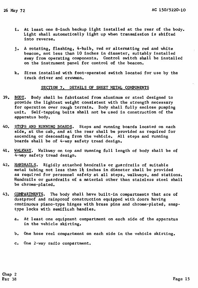
i. At least one 8-inch backup light installed at the rear of the body. Light shall automatically light up when transmission is shifted into reverse.
j. A rotating, flashing, 4-bulb, red or alternating red and white beacon, not less than 10 inches in diameter, suitably installed away from operating components. Control switch shall be installed on the instrument panel for control of the beacon.
k. Siren installed with foot-operated switch located for use by the truck driver and crewman.
SECTION 7. DETAILS OF SHEET METAL COMPONENTS
39. BODY. Body shall be fabricated from aluminum or steel designed to provide the lightest weight consistent with the strength necessary for operation over rough terrain. Body shall fully enclose pumping unit. Self-tapping bolts shall not be used in construction of the apparatus body.
40. STEPS AND RUNNING BOARDS. Steps and running boards located on each side, at the cab, and at the rear shall be provided as required for ascending or descending from the vehicle. All steps and running boards shall be of 4-way safety tread design.
41. WALKWAY. Walkway on top and running full length of body shall be of 4-way safety tread design.
42. HANDRAILS. Rigidly attached handrails or guardrails of suitable metal tubing not less than 1~ inches in diameter shall be provided as required for personnel safety at all steps, walkways, and stations. Handrails or guardrails of a material other than stainless steel shall be chrome-plated.
43. COMPARTMENTS. The body shall have built-in compartments that are of dustproof and rainproof construction equipped with doors having continuous piano-type hinges with brass pins and chrome-plated, snaptype locks with semiflush handles.
a. At least one equipment compartment on each side of the apparatus in the vehicle skirting.
b. One hose reel compartment on each side in the vehicle skirting.
c. One 2-way radio compartment.
Chap 2 Par 38 Page 15

AC 150/5200-10 26 May 72
SECl'ION 8, DETAILS OF FIRE FIGHTING EQUIPMENT AND COMPONENTS
44. PUMP(S) DRIVE. The pump(s) shall be driven by the vehicle engine(s) through a full torque power takeoff or proportioner which will permit operation of the pump(s) and the simultaneous operation of the vehicle. The pump(s) shall not be affected by changes in transmission ratios or the actuation of clutches in the vehicle drive, except insofar as these changes or actuations may affect engine speeds. The design of the drive system and controls shall prevent damage to the drive or lurching of the vehicle when the vehicle drive is engaged while pumping operations are in process. The pump(s) drive system shall be capable of absorbing the maximum torque delivered by the engine to the pump and withstand engagement of the pump(s) at all engine speeds and under all operating conditions,
45. PUMP(S), The pump(s) shall be of centrifugal type designed to provide both the capacity and high-pressure discharge required, When operating from the water tank as an aircraft fire fighting unit, the pump shall be capable of discharging:
a. 250 g.p.m. of water/foam solution at 150 p.s.i. minimum net pressure for Class I vehicles,
b. 500 g.p.m. of water/foam solution at 250 p.s,i. minimum net pressure for Class II vehicles.
c. 800 g.p,m. of water/foam solution at 250 p.s.i, minimum net pressure for Class Ill vehicles.
d. 1,200 g,p.m. of water/foam solution at 250 p.s.i. minimum net pressure.
46, PUMP CONNECTIONS.
a. Suction, At least one outside National Standard Fire Hose Thread (NSFHT) suction inlet with a strainer, cap, and suction connection to the water tank shall be provided. The suction size for:
(1) Class I vehicles is 2~ inches; and for
(2) Class II, III, and IV vehicles is ~ inches.
b. Discharge, The pump shall be provided with a minimum of two discharge gates with NSFHT adapters and caps. The discharge to the turrent shall be controlled from both inside and on the roof of the cab. The discharge to hose reels shall be controlled at
Chap 2 Page 16 Par 44

26 May 72 AC 150/5220-10
the reels. The discharge to the ground-sweep nozzles shall be controlled within the cab; these controls shall be accessible both to the driver and' a crewman when seated in their respective seats in the cab. The two discharge gates for:
(1) Class I vehicles is 1~ inches; and for
(2) Class II, III, and IV vehicles is 2~ inches.
47. HEAT EXCHANGER. A closed system heat exchanger and churn line to prevent overheating of water in pump when pump is operating at zero discharge, automatic or cab controlled, shall be provided.
48. PUMP AND ENGINE CONTROLS.
a. Control Panel. The main pump and engine control panel shall be located on the forward portion of the body at the suction intake immediately to the rear of the cab. This panel shall include the discharge gate controls, governor, primer, cooler, water and foam tank valve controls, churn valve control, and the following pumping unit instruments and controls:
Ignition Switch Tachometer
Starter Button Coolant Temperature Gauge
Pump Pressure Gauge Oil Pressure Gauge
Pump Compound Gauge Foam Tank Level Gauge
Throttle (Vernier Style) Water Tank Level Gauge
Choke (if manual)
b. Pressure Re2alator. The automatic pressure regulator shall be adjustable to maintain working pressures from 75 to 300 p.s.i. with an adjustment control located on the control panel.
c. Priming Device. The priming device to eKhaust air from the pumps and the suction hose for operating at draft shall be of the positive displacement type.
d. Remote Controls. Remote controls, in addition to those included in the control panel specified in paragraph 48a, shall be located in the vehicle cab. They are to be so situated that all manually
Chap 2 Par 46 Page 17
AC 150/5220-10 26 May 72
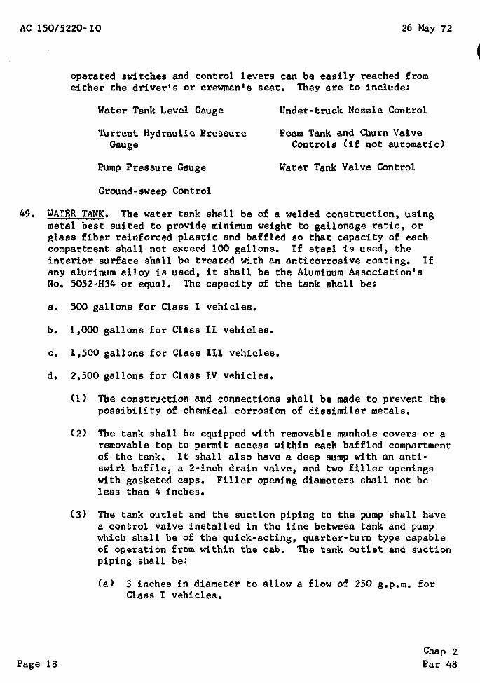
operated switches and control levers can be easily reached from either the driver's or crewman's seat, They are to include:
Water Tank Level Gauge Under-truck Nozzle Control
Turrent Hydraulic Pressure Foam Tank and Churn Valve Gauge Controls (if not automatic)
PUmp Pressure Gauge Water Tank Valve Control
Ground-sweep Control
49, WATER TANK. The water tank shall be of a welded construction, using metal best suited to provide minimum weight to gallonage ratio, or glass fiber reinforced plastic and baffled so that capacity of each compartment shall not exceed 100 gallons. If steel is used, the interior surface shall be treated with an anticorrosive coating. If any aluminum alloy is used, it shall be the Alu~num Association's No, 5052-H34 or equal. The capacity of the tank shall be:
a. 500 gallons for Class I vehicles,
b, 1,000 gallons for Class Il vehicles.
c, 1,500 gallons for Class III vehicles.
d, 2,500 gallons for Class IV vehicles,
(1) The construction and connections shall be made to prevent the possibility of chemical corrosion of dissimilar metals,
(2) The tank shall be equipped with removable manhole covers or a removable top to permit access within each baffled compartment of the tank. It shall also have a deep sump with an anti swirl baffle, a 2·inch drain valve, and two filler openings with gasketed caps. Filler opening diameters shall not be less than 4 inches,
(3) The tank outlet and the suction piping to the pump shall have a control valve installed in the line between tank and pump which shall be of the quick-acting, quarter-turn type capable of operation from within the cab, The tank outlet and suction piping shall be:
(a) 3 inches in diameter to allow a flow of 250 g,p,m, for Class 1 vehicles,
Chap 2 Page 18 Par 48

26 May 72 AC 150/5220-10
(b) 4 inches in diameter to allow a flow of 500 g,p,m. for Class II vehicles,
(c) 5 inches in diameter to allow a flow of 800 g.p.m. for Class III vehicles.
(d) 6 inches in diameter to allow a flow of 1,200 g.p.m. for Class IV vehicles.
(4) The tank shall be mounted in a manner which limits transfer of the torsional strains of off-pavement driving from the chassis frame to the tank. The tank shall be separate and distinct from the body and easily removable as a unit.
(5) The tank shall be provided with overflow connection(s) which shall prevent excess pressure being applied to the tank during filling operations.
50. TANK FILLER CONNECTION. A tank filler connection shall be provided at the rear of the apparatus in a position where it can be reached from the ground. It shall include an automatic valve means for shutting off the flow of water when the tank is 75 to 80 percent full and for reopening the valve as the tank empties. The connection shall be so constructed that water shall not be lost from the tank when connection or disconnection is made. It shall terminate in a 2~-inch NSFHT swivel female hose connection. All water fill openings shall be provided with strainers. The tank filler piping for:
a. Class I vehicles shall be 2~-inches; and for
b. Class II, III, and IV vehicles shall be 3 inches.
51. FOAM PROPORTIONING SYSTEM. The purchaser shall select the type of foam proportioning system desired from the following types:
a. A Pump Discharge Side Balanced Pressure Proportioning System to automatically control the ratio of foam concentrate to the quantity of water being discharged shall consist of:
(1) A pump to deliver the foam concentrate at a slightly higher pressure than that of the water on the discharge side of the pump.
(2) A pressure control valve to automatically bypass sufficient foam concentrate back to the storage tank to produce and maintain a foam concentrate pressure exactly equal to the water pump discharge pressure.
Chap 2 Par 49 Page 19
AC 150/5220-10 26 May 72
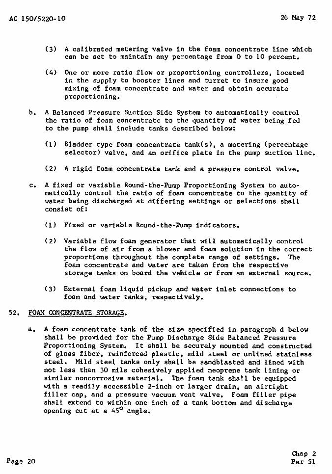
(3) A calibrated metering valve in the foam concentrate line which can be set to maintain any percentage from 0 to 10 percent.
(4) One or more ratio flow or proportioning controllers, located in the supply to booster lines and turret to insure good mixing of foam concentrate and water and obtain accurate proportioning.
b. A Balanced Pressure Suction Side System to automatically control the ratio of foam concentrate to the quantity of water being fed to the pump shall include tanks described below:
(1) Bladder type foam concentrate tank(s), a metering (percentage selector) valve, and an orifice plate in the pump suction line.
(2) A rigid foam concentrate tank and a pressure control valve.
c. A fixed or variable Round-the-Pump Proportioning System to automatically control the ratio of foam concentrate to the quantity of water being discharged at differing settings or selections shall consist of:
(1) Fixed or variable Round-the-Pump indicators.
(2) Variable flow foam generator that will automatically control the flow of air from a blower and foam solution in the correct proportions throughout the complete range of settings. The foam concentrate and water are taken from the respective storage tanks on board the vehicle or from an external source.
(3) External foam liquid pickup and water inlet connections to foam and water tanks, respectively.
52. FOAM CONCENTRATE STORAGE.
a. A foam concentrate tank of the size specified in paragraph d below shall be provided for the Pump Discharge Side Balanced Pressure Proportioning System. It shall be securely mounted and constructed of glass fiber, reinforced plastic, mild steel or unlined stainless steel. Mild steel tanks only shall be sandblasted and lined with not less than 30 mils cohesively applied neoprene tank lining or similar noncorrosive material. The foam tank shall be equipped with a readily accessible 2-inch or larger drain, an airtight filler cap, and a pressure vacuum vent valve. Foam filler pipe shall extend to within one inch of a tank bottom and discharge opening cut at a 45° angle.
Chap 2 Page 20 Par 51
26 May 72 AC 150/5220-10
b. When bladder type foam concentrate tanks are used with a Balanced Pressure Suction Side System, they shall be mounted within the water tank and of size specified in paragraph d below.
c. When a rigid foam concentrate tank is to be used with the Balanced Pressure Suction Side or Round-the-Pump Proportioning System, together with a pressure control valve, the tank shall be of a size specified in paragraph d below, constructed as described in paragraph a above, and securely mounted on the upper surface of the water tank.
d. The capacity of the foam storage tanks shall be:
(1) 100 gallons for Class I vehicles.
( 2) 200 gallons for Class II vehicles.
(3) 300 gallons for Class III vehicles.
(4) 500 gallons for Class IV vehicles.
e. A glass fiber reinforced plastic or mild steel fill pan equipped with a ~-inch mesh steel screen and one stainless steel can opener to permit emptying a 5-gallon foam concentrate can shall be provided. This fill pan shall be connected to the foam storage tank(s) with a 2-inch pipe for filling the storage tank(s). The storage tank(s) shall be equipped with a suitable vent to expedite filling,
f. Provisions shall be made for flushing all of the foam system piping with clear water from the pump discharge.
53. nJRRET.
a. There shall be one manual turret designed to discharge foam solution, water, or water fog at the rates listed below. (If desired, the purchaser may specify hydraulic controlled turrets as described in paragraph 68d,)
(1) Class 1 single barrel 200 g.p,m.
(2) Class II single barrel 400 g.p.m,
(3) Class III double barrel 300 g.p.m. each, barrel total discharge 600 g,p,m.
(4) Class IV double barrel 500 g.p.m. each, barrel total discharge 1,000 g.p.m,
Chap 2 Par 52 Page 21

AC 150/5220·10 26 May 72
b, Necessary controls will be provided to permit the selection of the foam solution, water, or water fog from both inside the cab and on the cab roof, The turret shall be aimed by a single, directconnected control lever, The turret shall also have a complete set of controls to permit manual operation from on top the cab roof.
c. The turret shall have a discharge pattern which is infinitely variable from a flat pattern to a solid stream of foam, The resulting foam shall have a minimum expansion of 8 to 1 with not more than 25 percent drainage time of at least 5 minutes, All foam patterns listed shall be at an operating pressure of 200 p,s,i, The turret discharge pattern for each class vehicle is as follows:
(1) Class I flat pattern will have 25-foot width and SO-foot range, The solid stream pattern will have a 120-foot range,
(2) Class II flat pattern will have 25-foot width and 60-foot range, The solid stream pattern will have a 130-foot range,
(3) Class 111 and IV flat patterns will have 25-foot width and 60-foot range. The solid stream pattern will have a 150-foot range,
54, HANDLINE REELS AND NOZZLES, Two manual rewind hose reels, one on each side of the vehicle, shall be provided,
a. Class I vehicle handline reels shall be located on or over the water tank and shall be provided with vertical and horizontal captive type rollers,
b. Class II, Ill, and IV vehicle handline reels each shall be located in a compartment and mounted on a vertical hinge post permitting reel to swing out at a 70° angle to vehicle, A lock with a quick release shall be provided for locking in either operating or bed position, Each reel shall be equipped for automatic charging of the handline hose when released from the bed position, Manual pull type valves shall be located so the hose can also be changed in the bed position. Hose rollers are to be provided on the front corners of the apparatus.
c, Each reel shall have a capacity for, and be equipped with, a minimum of 150 feet of l-inch, 800-pound test rubber-lined hose, Each reel shall be equipped with a friction brake to provide a positive control for unreeling of the hose,
Chap 2 Page 22 Par 53

26 May 72 AC 150/5220-10
d. Each hose shall be equipped with a shutoff type nozzle designed for selection of discharging of foam, water, or water fog, The foam produced by the nozzle shall have a minimum expansion ratio of 8 to 1 with not more than 25 percent drainage of 5 minutes. Foam pattern shall be at a nozzle operating pressure of 100 p.s.i. Each nozzle shall have a foam discharge pattern from a flat 15-foot width and a 20-foot range to a solid stream of foam. The discharge rate for each nozzle shall be:
(1) Class 1 vehicle, 50 g.p.m.
(2) Class II and Ill vehicles, 60 g.p.m.
(3) Class IV vehicle, 100 g.p.m.
55, GROUND-SWEEP NOZZLE(S), Ground-sweep nozzle(s) shall be provided and shall be capable of producing a foam pattern 12 feet wide with a 25foot range, The resulting foam shall have a minimum expansion ratio of 8 to 1 with not more than 25 percent drainage in 5 minutes, The nozzle control shall be readily accessible from the driver's seat, The discharge rate shall be:
a. Class I and 11 vehicles, 60 g.p,m,
b. Class II vehicle, 100 g,p.m.
c, Class IV vehicle, 250 g.p.m.
56, DRY CHEMICAL SYSTEM. The Class 1 ~ehicle only shall be provided with a stationary type 300-pound dry chemical system, listed and approved by a recognized testing laboratory for fire extinguishing systems, and shall be mounted directly behind the vehicle cab, The system shall be complete with tank, pressurization facilities, and 100 feet of threefourth-inch hose with nozzle of manufacturer's latest design.
57. AUXILIARY EQUIPMENT. The following auxiliary equipment shall be provided and shall be properly mounted on the vehicle or secured in a compartment,
a. Extension ladder, fire department type, one 2-section capable of being extended to 18 feet; this ladder to be of light-weight alloy 18 inches wide, 12-inch spacing between rungs, and mounted in quick release brackets on side of vehicle,
b, Two electric hand lanterns, 6V battery, to throw 1,000-foot beam.
c. Two axes, fire pickhead, 6-pound, with serrated blade,
Chap 2 Par 54 Page 23

AC 150/5220-10 26 May 72
d. One adjustable hydrant wrench.
e. Two 2~-inch spanner wrenches.
f. Two l-inch spanner wrenches.
SECTION 9. MISCELLANEOUS DETAILS
58. RADIO INTERFERENCE.SUPPRESSION. The vehicle shall be adequately radio interference suppressed to permit positive understandable voice radio communications under all operating conditions.
59. TREATING AND PAINTING.
a. All parts of the vehicle shall be cleaned, treated, and primed prior to assembly.
b. After the vehicle is completely assembled, except for bright trim parts, the entire unit shall be primed, puttied, water sanded, and painted with not less than three coats of red enamel (Red No. 11136 of Federal Standard No. 595).
c. The finished paint shall be free from "orange peel" (pebbly finish), runs, and other imperfections which detract from the vehicle's appearance.
60. TOOLS. Any tools peculiar to the servicing of the vehicle, the fire suppression system, and any of the auxiliary equipment shall be furnished with the vehicle.
61. NAMEPLATES AND INSTRUCTION PLATES. All nameplates and instruction plates shall be metal or plastic with the information engraved, stamped, or etched thereon. If metal, they shall be made of a noncorrosive material, chrome plated, or nickel silvered. These plates shall be attached with scre1~s, bolts, or rivets. Each plate shall be mounted in a conspicuous place.
a. Plastic plates shall not be used in exposed positions where they are subject to weathering.
b. Nameplates shall show make, model, serial number, and other such data as to positively identify the item.
c. Instruction plates shall be on each handle (exclusive of door handles), valves, or component parts which necessitate actuation or identification or important instructions to be followed in operating or servicing the vehicle or equipment. These instruc· tion plates shall include warnings or cautions and shall be so located and of sufficient size to be effective.
Chap 2 Page 24 Par 57

26 May 72 AC 150/5220-10
62. LUBRICATION AND HYDRAULIC FLUIDS. All moving parts requiring lubrication shall have means provided for such lubrication. Pressure lubrication fittings shall not be provided where their normal use would damage grease seals or other parts. Prior to delivery, the vehicle shall be lubricated with lubricants suitable for use in the temperature ranges where the vehicle is to be placed in service. All hydraulic systems shall be filled to the proper operating level with the correct grade of hydraulic fluid for the same temperature range.
63. TECHNICAL PUBLICATIONS. The contractor shall furnish two sets of the following publications in accordance with standard commercial practices applicable to the vehicle (including body and special equipment) furnished under the contract. Each set shall be composed of one copy each of:
a. Operator's Manual with Lubrication Charts.
b. Parts Manual.
c. Maintenance and Service Manual.
Chap 2 Par 62 Page 25 (and 26)

26 Ma}' 72 AC 150/5220-10
CHAPTER 3. QUALITY ASSURANCE PROVISION
64. GENERAL. The contractor is responsible for the performance of all inspection requirements as specified herein. Except as otherwise specified, the contractor may utilize his own or any other inspection facilities and services. Records oe inspections and tests shall be maintained by the contractor. Copies of these records shall be provided the purchaser. The purchaser reserves-the right to perform any of the inspections set forth in the specification-where such inspections are deemed necessary to assure contractor·compliance with the specifi cation requirements.
65. INSPECTIONS AND TESTS PROCEDURES. These tests will be conducted at purchaser's location by the vehicle manufacturer's delivery engineer.
a •. Operational Tests. During these tests, the functioning of the engine, power train, hydraulic system, brakes, steering, lighting system, controls, and instruments shall be observed. The vehicle shall be fully loaded as to its rated GVW as specified in paragraph 7a and shall be operated as follows:
(1) 20 miles over hard surfaced roads at maximum speeds not less than 40 m.p.h.
(2) 10 miles over dirt surfaced roads at maximum road speeds up to 25 m.p.h.
(3) 10 miles off highway at speeds up to 15 m.p.h. with ground and grade conditions requiring all-wheel drive.
(4) One hour at not more than 3 m.p.h. over all types of terrain encountered in cross-country travel.
(5) Accelerate from 0 to 50 m.p.h. in the time specified in paragraph 9a on dry level pavement free from loose materials.
b. Pump Tests.
(1) Pressure and Capacity. The pump shall be tested to determine conformance with paragraph 45 at approximately 10-foot suction lifts. Capacity of the pump shall be measured with calibrated instruments. Copies of official pump test report, certified by the inspector, shall be included with the technical publi cations supplied with the vehicle.
Chap 3 Par 64 Page 27

AC 150/5220-10 26 May 72
(2) Foam Tests. The contractor shall provide one complete change of foam concentrate which may be used in conducting the following tests:
(a) Tests shall be conducted to determine the capacity of the turret(s) and nozzle(s) to discharge foam, water, and water fog as described in paragraph 53 and paragraph 54d.
(b) Foam discharge patterns and drainage characteristics shall meet the criteria contained in paragraphs 53c and 54d,
c. Gradability.
(1) Negotiate an 8 percent grade at a speed of not less than 20 m.p.h. The purchaser may elect to accept a certified performance chart from the contractor showing the vehicle's performance in all gear ratios at all engine r.p.m. above 1,000 r.p.m.
(2) The loaded vehicle shall negotiate side slopes left and right of 20 percent grade.
d. Brake Tests.
(l) Bring the fully loaded vehicle to 5 complete, successive stops within 30 feet from 20 m.p.h., using service brakes only, on dry, hard pavement free from loose material.
(2) Bring the fully loaded vehicle to a complete stop from 20 m.p.h. and hold the vehicle on the ~ximum grades at the airport, using hand brakes only,
e, Radio Interference. Tests for radio interference suppression shall be conducted on the vehicle. All testing equipment, instruments, personnel for making the tests, the test location (which shall be reasonably free from radiated and conducted interference), and other necessary facilities shall be furnished by the contractor,
66, PREPARATION FOR DELIVERY.
a, Domestic Shipment. The vehicle and its accessories, spare parts, and tools shall be packed in such a manner as to insure acceptance and safe delivery to the designated point,
b, Overseas Shipment, When specified in the invitation-to-bid, the packing for shipment overseas shalt be in accordance with the instructions issued by the purchaser,
c, Marking. Marking for shipment shalt be in accordance with instructions issued by the purchaser,
Chap 3 Page 28 Par 65

26 May 72 AC 150/5220-10
67. WARRANTY. The contractor shall warrant each new apparatus manufactured or assembled by him to be free from defects in material and workmanship under normal use and service. His obligation under this warranty is limited to making good at his factory any part or parts thereof, including all equipment or trade accessories (except tires, storage batteries, electric lamps, and other devices subject to normal deterioration) supplied by him. Parts developing defects within one year after making delivery of such vehicle to the original purchaser must be returned to contractor with transportation charges prepaid and which on examination by the manufacturer shall disclose to his satisfaction to have been thus defective.
68. PRODUCTION OPTIONS. Production options and components, which purchasers may wish to consider, are described below. These options are written so that the descriptive material may be added to or substituted for the applicable paragraph of the specification.
a. After paragraph 55, add a paragraph titled "Under-Truck Nozzles". "Under-truck nozzles shall be furnished. These nozzles shall be located so their discharge effectively blankets the ground under the full length of the vehicle with foam. The nozzle control shall be readily accessible from the driver's seat. Nozzles shall have a minimum range of 10 feet. These nozzles should be required if the vehicle is undercoa ted."
b. Add the following to paragraph 59: "The vehicle shall be undercoated with a fibrous reinforced asphaltic compound of the manufacturer's standard sandless commercial material. The coating shall be 1/16- to 1/8-inch thick and applied to clean, dry surfaces except engine, transmission, drive shafts, axles, brakes, and steering and suspension components."
c. If a need for limited structural fire fighting capabilities is anticipated, any or all of the following items should be included and properly mounted:
(1) Two 10-foot lengths of a suitable size hard suction hose with chrome-plated couplings with NSFHT.
(2) One chrome-plated suction strainer of suitable size barrel type with NSFHT.
(3) One suction hose coupling, double female, 4\-inch NSFHT to local hydrant thread.
Chap 3 Par 67 Page 29

AC 150/5220-10 CHG 1 4 Dec 72
(4) Ten 50-foot sections of 21;-inch double-jacket rubberlined hose. (1-\!-inch hose with nozzles and necessary fittings may be included if desired by purchaser,)
(5) Two 2-\!-inch nozzles with NSFHT. Each nozzle to include playpipe, shutoff valve, and 3 smooth bore tips (tips to be 1, 1-1/8, and 1-1/4 inches).
(6) One 2-\!-inch double female connection, NSFHT.
d. Substitute either of two following paragraphs for paragraph 53a:
(1) There shall be two turrets either hydraulically or manually remotely controlled. Each turret shall have individual discharge capability of 500 g.p.m.
(2) There shall be one single barrel type turret with dual-rated output controls, The discharge shall vary from 500 to 1,000 g.p.m. of a foam solution or water, The turret shall be manually controlled from the turret position on top of the cab roof or by the driver/operator within the vehicle cab.
e. Additional aircraft fire and rescue equipment: Flat step aircraft rescue ladder, 18 feet in length, 24 inches in width; this ladder to be made of light-weight alloy and with a folding guardrail and mounted in quick release brackets on side of vehicle,
* f. After paragraph 44, add a paragraph titled "Pump Engine:"
"An independent pump engine may be provided of not less than 6 cyliners, having sufficient power to meet the pump performance requirements as listed in paragraph 45 without the engine exceeding the "no load" governed speed at the peak of a certified gross BHP curve. The engine shall have a 12-volt ignition system, oil bath air cleaner, full-flow or bypass replaceable element oil filter, full pressure lubrication system, and overspeed governing device to prevent damage to engine if under power v1hen tank is exhausted. The engine shall be provided with either a supplementary heat exchange cooling system in addition to the standard radiation, which shall circulate cold water from the tank through the heat exchanger and back to tank, or a shrouded radiator of adequate capacity to cool the engine when operated continuously under full load up to l00°F ambient temperature," *
Chap 3 Page 30 Par 68