Datasheet Unibox 14
45
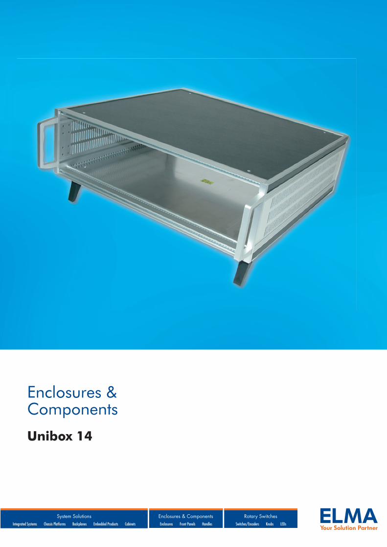
Enclosures & Components Unibox 14
-
Upload
kathrin-fessler -
Category
Documents
-
view
233 -
download
0
description
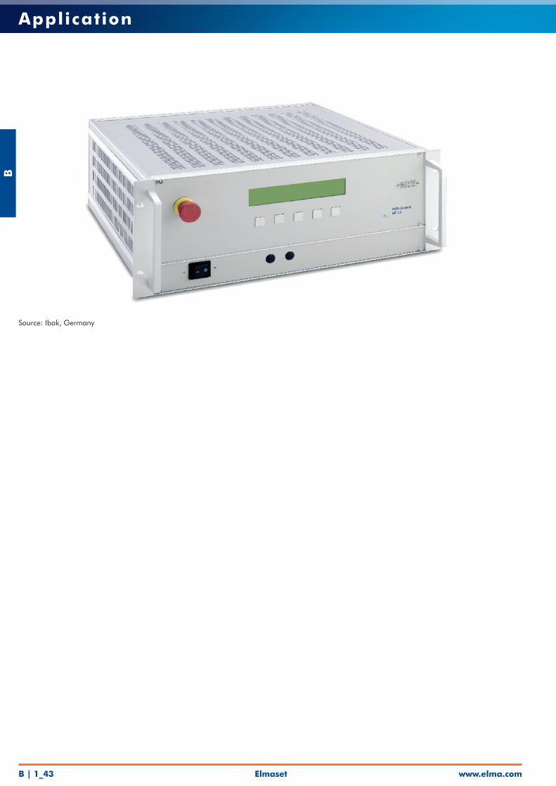
Universal case usable as sub rack or as desktop case.
Transcript of Datasheet Unibox 14
Enclosures & Components
Unibox 14
B
www.elma.comElmasetB | 1_1
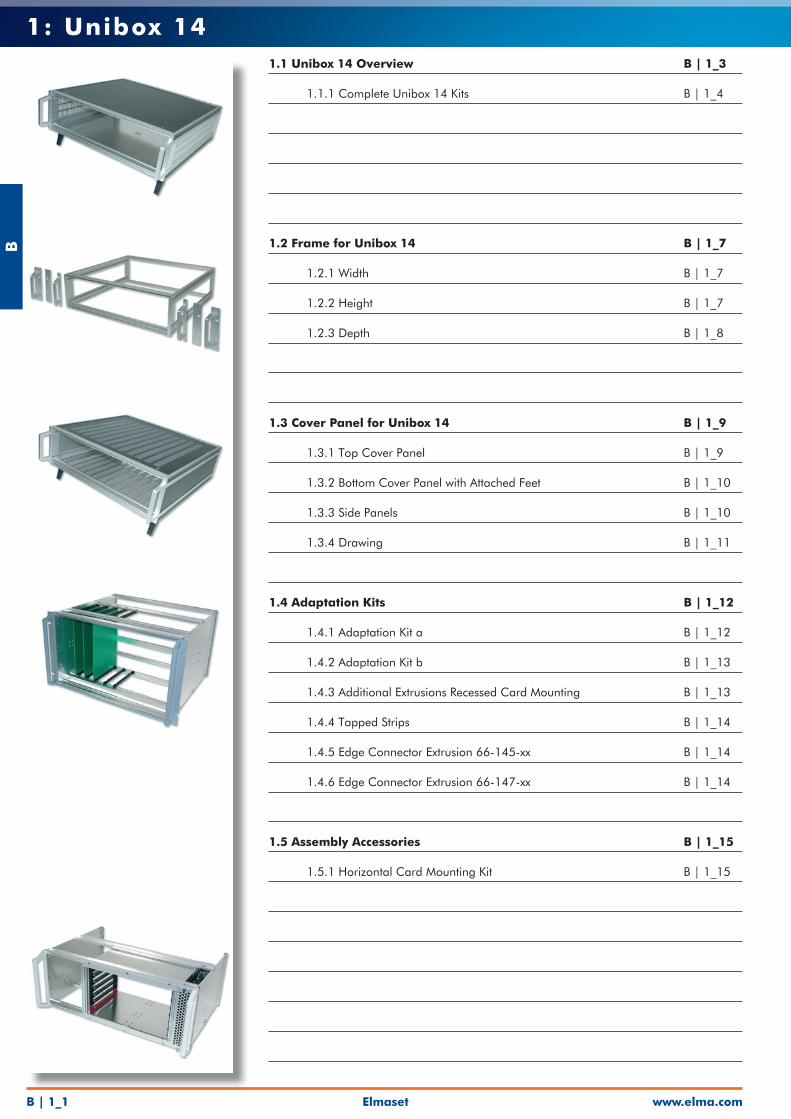
1: Unibox 141.1 Unibox 14 Overview B | 1_3
1.1.1 Complete Unibox 14 Kits B | 1_4
1.2 Frame for Unibox 14 B | 1_7
1.2.1 Width B | 1_7
1.2.2 Height B | 1_7
1.2.3 Depth B | 1_8
1.3 Cover Panel for Unibox 14 B | 1_9
1.3.1 Top Cover Panel B | 1_9
1.3.2 Bottom Cover Panel with Attached Feet B | 1_10
1.3.3 Side Panels B | 1_10
1.3.4 Drawing B | 1_11
1.4 Adaptation Kits B | 1_12
1.4.1 Adaptation Kit a B | 1_12
1.4.2 Adaptation Kit b B | 1_13
1.4.3 Additional Extrusions Recessed Card Mounting B | 1_13
1.4.4 Tapped Strips B | 1_14
1.4.5 Edge Connector Extrusion 66-145-xx B | 1_14
1.4.6 Edge Connector Extrusion 66-147-xx B | 1_14
1.5 Assembly Accessories B | 1_15
1.5.1 Horizontal Card Mounting Kit B | 1_15
Elmaset
B
www.elma.com B | 1_2
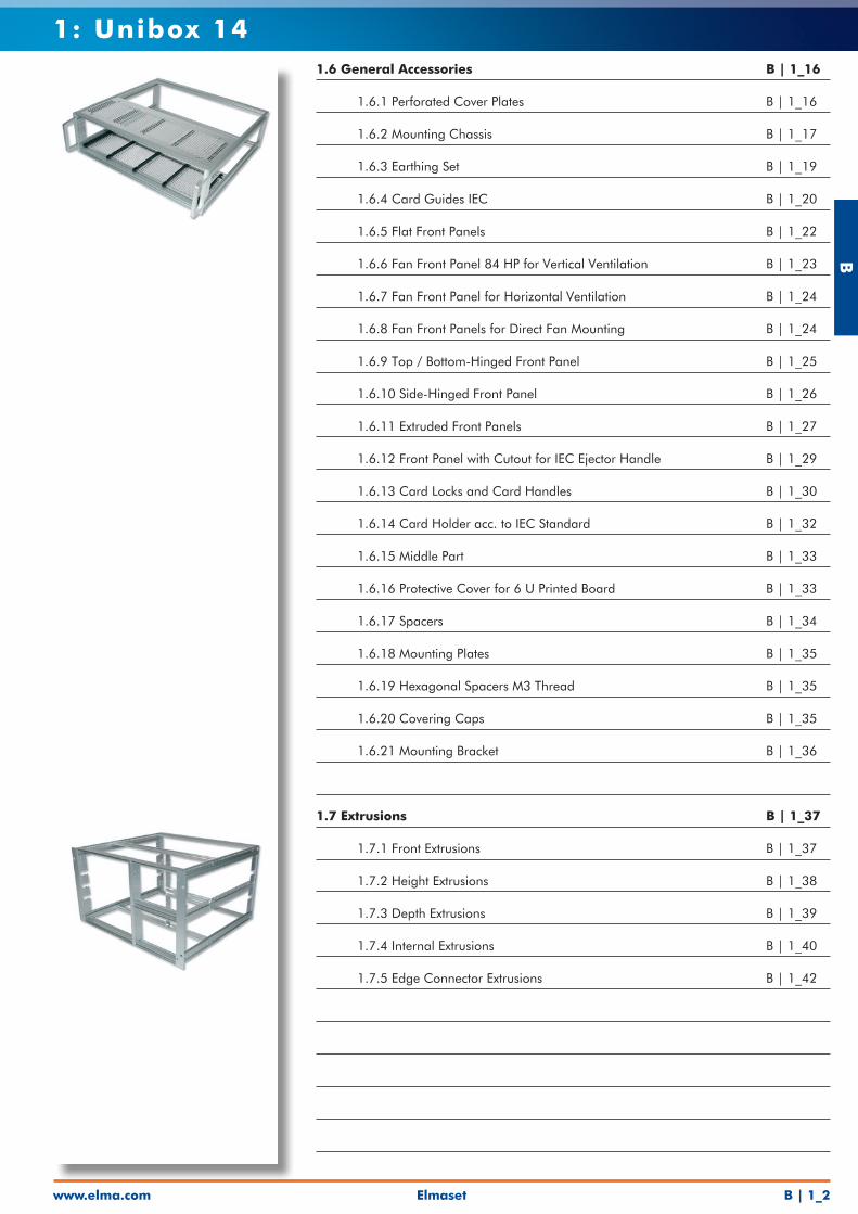
1: Unibox 141.6 General Accessories B | 1_16
1.6.1 Perforated Cover Plates B | 1_16
1.6.2 Mounting Chassis B | 1_17
1.6.3 Earthing Set B | 1_19
1.6.4 Card Guides IEC B | 1_20
1.6.5 Flat Front Panels B | 1_22
1.6.6 Fan Front Panel 84 HP for Vertical Ventilation B | 1_23
1.6.7 Fan Front Panel for Horizontal Ventilation B | 1_24
1.6.8 Fan Front Panels for Direct Fan Mounting B | 1_24
1.6.9 Top / Bottom-Hinged Front Panel B | 1_25
1.6.10 Side-Hinged Front Panel B | 1_26
1.6.11 Extruded Front Panels B | 1_27
1.6.12 Front Panel with Cutout for IEC Ejector Handle B | 1_29
1.6.13 Card Locks and Card Handles B | 1_30
1.6.14 Card Holder acc. to IEC Standard B | 1_32
1.6.15 Middle Part B | 1_33
1.6.16 Protective Cover for 6 U Printed Board B | 1_33
1.6.17 Spacers B | 1_34
1.6.18 Mounting Plates B | 1_35
1.6.19 Hexagonal Spacers M3 Thread B | 1_35
1.6.20 Covering Caps B | 1_35
1.6.21 Mounting Bracket B | 1_36
1.7 Extrusions B | 1_37
1.7.1 Front Extrusions B | 1_37
1.7.2 Height Extrusions B | 1_38
1.7.3 Depth Extrusions B | 1_39
1.7.4 Internal Extrusions B | 1_40
1.7.5 Edge Connector Extrusions B | 1_42
B
www.elma.comElmasetB | 1_3
1: Unibox 14
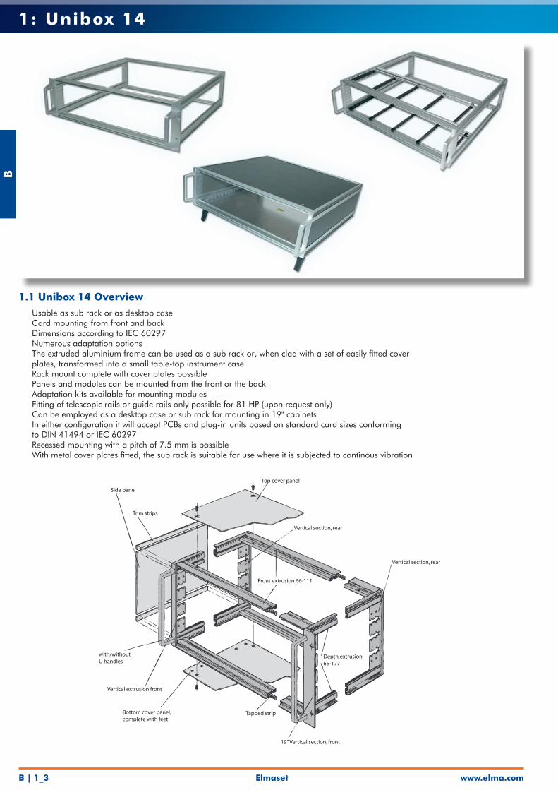
1.1 Unibox 14 Overview• Usable as sub rack or as desktop case• Card mounting from front and back• Dimensions according to IEC 60297• Numerous adaptation options• The extruded aluminium frame can be used as a sub rack or, when clad with a set of easily fitted cover
plates, transformed into a small table-top instrument case• Rack mount complete with cover plates possible• Panels and modules can be mounted from the front or the back• Adaptation kits available for mounting modules• Fitting of telescopic rails or guide rails only possible for 81 HP (upon request only)• Can be employed as a desktop case or sub rack for mounting in 19" cabinets• In either configuration it will accept PCBs and plug-in units based on standard card sizes conforming
to DIN 41494 or IEC 60297• Recessed mounting with a pitch of 7.5 mm is possible• With metal cover plates fitted, the sub rack is suitable for use where it is subjected to continous vibration
Trim strips
Side panel
Top cover panel
Vertical section, rear
Vertical section, rear
Front extrusion 66-111
with/withoutU handles
Vertical extrusion front
Bottom cover panel,complete with feet
Tapped strip
19” Vertical section, front
Depth extrusion66-177
Elmaset
B
www.elma.com B | 1_4
1: Unibox 14
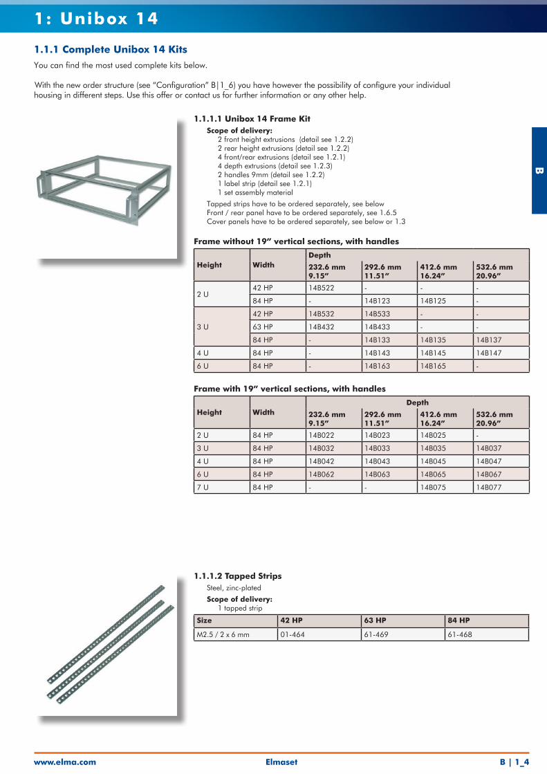
1.1.1 Complete Unibox 14 KitsYou can find the most used complete kits below.
With the new order structure (see “Configuration” B|1_6) you have however the possibility of configure your individual housing in different steps. Use this offer or contact us for further information or any other help.
1.1.1.1 Unibox 14 Frame Kit• Scope of delivery: • 2 front height extrusions (detail see 1.2.2) • 2 rear height extrusions (detail see 1.2.2) • 4 front/rear extrusions (detail see 1.2.1) • 4 depth extrusions (detail see 1.2.3) • 2 handles 9mm (detail see 1.2.2) • 1 label strip (detail see 1.2.1) • 1 set assembly material
• Tapped strips have to be ordered separately, see below• Front / rear panel have to be ordered separately, see 1.6.5• Cover panels have to be ordered separately, see below or 1.3
Frame without 19” vertical sections, with handles
Height WidthDepth
232.6 mm9.15”
292.6 mm11.51”
412.6 mm16.24”
532.6 mm20.96”
2 U42 HP 14B522 - - -
84 HP - 14B123 14B125 -
3 U
42 HP 14B532 14B533 - -
63 HP 14B432 14B433 - -
84 HP - 14B133 14B135 14B137
4 U 84 HP - 14B143 14B145 14B147
6 U 84 HP - 14B163 14B165 -
Frame with 19” vertical sections, with handles
Height WidthDepth
232.6 mm9.15”
292.6 mm11.51”
412.6 mm16.24”
532.6 mm20.96”
2 U 84 HP 14B022 14B023 14B025 -
3 U 84 HP 14B032 14B033 14B035 14B037
4 U 84 HP 14B042 14B043 14B045 14B047
6 U 84 HP 14B062 14B063 14B065 14B067
7 U 84 HP - - 14B075 14B077
1.1.1.2 Tapped Strips• Steel, zinc-plated
• Scope of delivery: • 1 tapped strip
Size 42 HP 63 HP 84 HP
M2.5 / 2 x 6 mm 01-464 61-469 61-468
B
www.elma.comElmasetB | 1_5
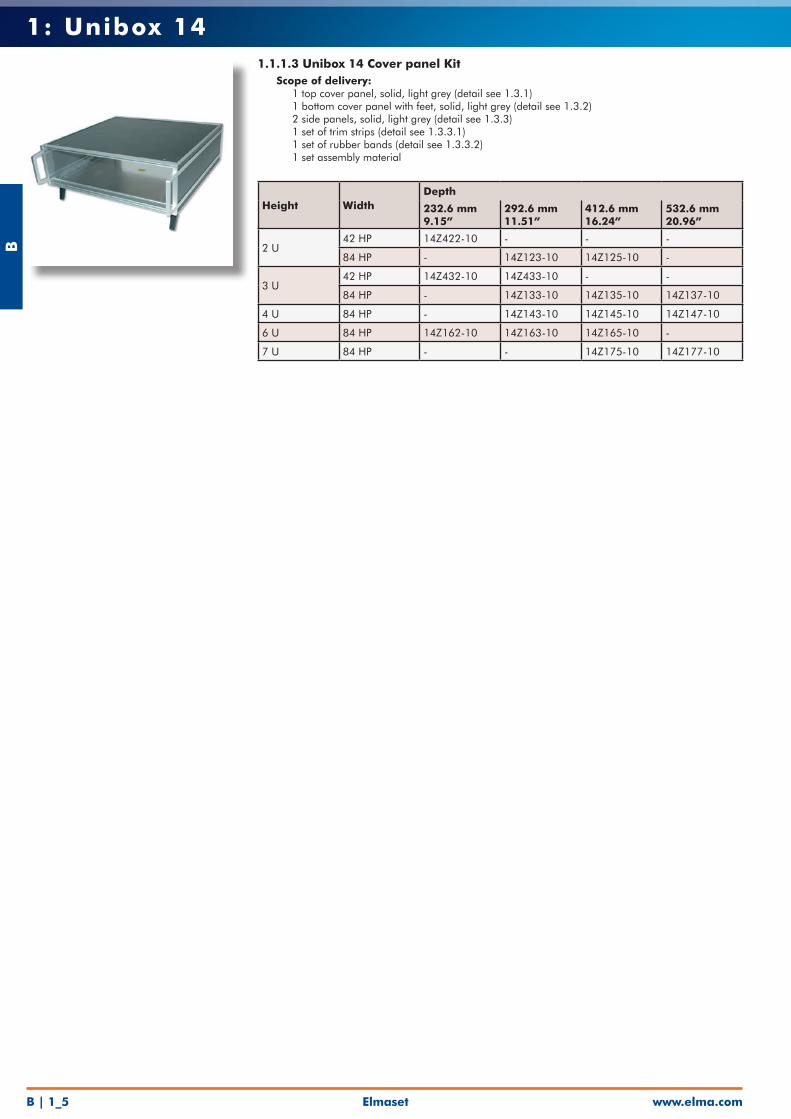
1: Unibox 141.1.1.3 Unibox 14 Cover panel Kit • Scope of delivery: • 1 top cover panel, solid, light grey (detail see 1.3.1) • 1 bottom cover panel with feet, solid, light grey (detail see 1.3.2) • 2 side panels, solid, light grey (detail see 1.3.3) • 1 set of trim strips (detail see 1.3.3.1) • 1 set of rubber bands (detail see 1.3.3.2) • 1 set assembly material
Height WidthDepth
232.6 mm9.15”
292.6 mm11.51”
412.6 mm16.24”
532.6 mm20.96”
2 U42 HP 14Z422-10 - - -
84 HP - 14Z123-10 14Z125-10 -
3 U42 HP 14Z432-10 14Z433-10 - -
84 HP - 14Z133-10 14Z135-10 14Z137-10
4 U 84 HP - 14Z143-10 14Z145-10 14Z147-10
6 U 84 HP 14Z162-10 14Z163-10 14Z165-10 -
7 U 84 HP - - 14Z175-10 14Z177-10
Elmaset
B
www.elma.com B | 1_6
1: Unibox 14
1.2.2.1 Handles
1.2.1.2 Label Strips
1.4 Adaptation Kits
1.5 Assembly Accessories
1.6 General Accessories
1.7 Extrusions
Trim Strip1.3.3.1
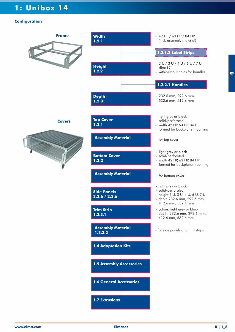
Configuration
Width1.2.1
Height1.2.2
Depth1.2.3
Top Cover1.3.1
Bottom Cover1.3.2
Side Panels2.2.6 / 2.3.6
Frame
Covers
- 42 HP / 63 HP / 84 HP (incl. assembly material))
- 2 U / 3 U / 4 U / 6 U / 7 U- slim/19"- with/without holes for handles
- 232.6 mm, 292.6 mm, 532.6 mm, 412.6 mm
- light grey or black- solid/perforated- width 42 HP, 63 HP, 84 HP- formed for backplane mounting
- for side panels and trim strips
- light grey or black- solid/perforated- height 2 U, 3 U, 4 U, 6 U, 7 U- depth 232.6 mm, 292.6 mm, 412.6 mm, 532.1 mm
- light grey or black- solid/perforated- width 42 HP, 63 HP, 84 HP- formed for backplane mounting
Assembly Material
Assembly Material
- colour: light grey or black- depth: 232.6 mm, 292.6 mm, 412.6 mm, 532.6 mm
Assembly Material1.3.3.2
- for top cover
- for bottom cover
B
www.elma.comElmasetB | 1_7
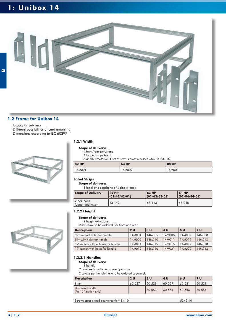
1: Unibox 14
1.2 Frame for Unibox 14• Usable as sub rack• Different possibilities of card mounting• Dimensions according to IEC 60297
1.2.1 Width
• Scope of delivery: • 4 front/rear extrusions • 4 tapped strips M2.5 • Assembly material: 1 set of screws cross recessed M4x10 (63-109)
42 HP 63 HP 84 HP
14M001 14M002 14M003
Label Strips• Scope of delivery: • 1 label strip consisting of 4 single tapes
Scope of Delivery 42 HP (01-42/42-01)
63 HP(01-63/63-01)
84 HP(01-84/84-01)
2 pcs. each (upper and lower)
63-142 63-143 63-046
1.2.2 Height
• Scope of delivery: • 2 height extrusions• 2 sets have to be ordered (for front and rear)
Description 2 U 3 U 4 U 6 U 7 U
Slim without holes for handle 14M004 14M005 14M006 14M007 14M008Slim with holes for handle 14M009 14M010 14M011 14M012 14M01319" section without holes for handle 14M014 14M015 14M016 14M017 14M01819" section with holes for handle 14M019 14M020 14M021 14M022 14M023
1.2.2.1 Handles• Scope of delivery: • 1 handle• 2 handles have to be ordered per case• 2 screws per handle have to be ordered separately
Description 2 U 3 U 4 U 6 U 7 U
9 mm 60-527 60-528 60-529 60-531 60-529Universal handle (for 19” section only)
60-553 60-554 60-556 60-554
Screws cross sloted countersunk M4 x 10 5342-10
Elmaset
B
www.elma.com B | 1_8
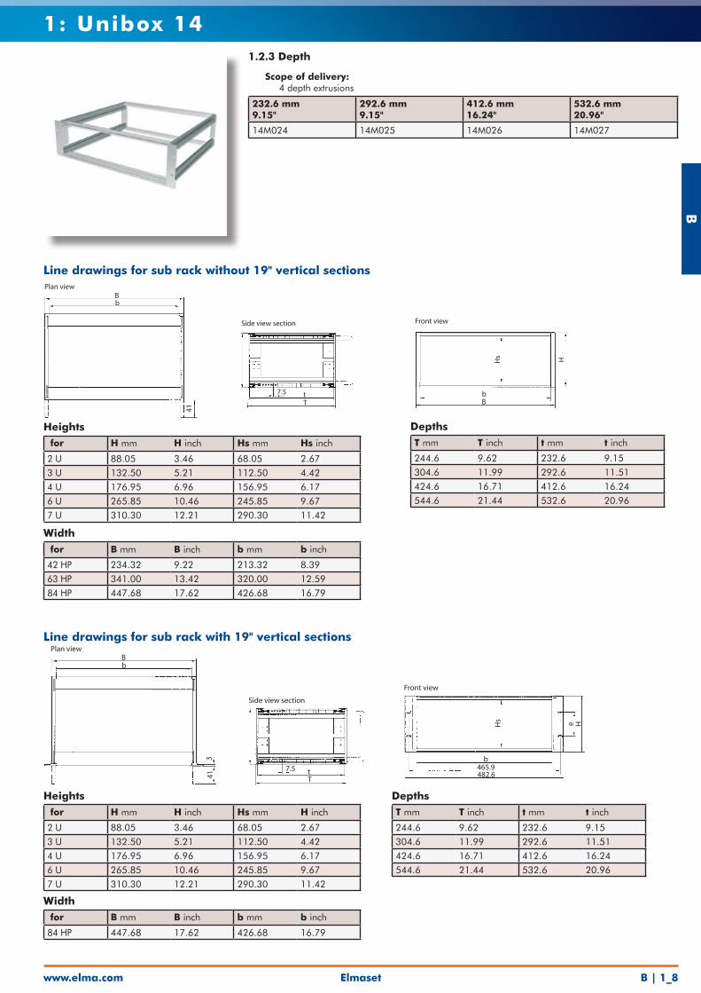
1: Unibox 141.2.3 Depth
• Scope of delivery: • 4 depth extrusions
232.6 mm9.15"
292.6 mm9.15"
412.6 mm16.24"
532.6 mm20.96"
14M024 14M025 14M026 14M027
Heights for H mm H inch Hs mm Hs inch
2 U 88.05 3.46 68.05 2.673 U 132.50 5.21 112.50 4.424 U 176.95 6.96 156.95 6.176 U 265.85 10.46 245.85 9.677 U 310.30 12.21 290.30 11.42
DepthsT mm T inch t mm t inch
244.6 9.62 232.6 9.15304.6 11.99 292.6 11.51424.6 16.71 412.6 16.24544.6 21.44 532.6 20.96
Width for B mm B inch b mm b inch
42 HP 234.32 9.22 213.32 8.3963 HP 341.00 13.42 320.00 12.5984 HP 447.68 17.62 426.68 16.79
Line drawings for sub rack without 19" vertical sections
Hs H
bB
Front view
7.5 tT
Side view section
Bb
41
Plan view
Heights for H mm H inch Hs mm H inch
2 U 88.05 3.46 68.05 2.673 U 132.50 5.21 112.50 4.424 U 176.95 6.96 156.95 6.176 U 265.85 10.46 245.85 9.677 U 310.30 12.21 290.30 11.42
DepthsT mm T inch t mm t inch
244.6 9.62 232.6 9.15304.6 11.99 292.6 11.51424.6 16.71 412.6 16.24544.6 21.44 532.6 20.96
Width for B mm B inch b mm b inch
84 HP 447.68 17.62 426.68 16.79
Line drawings for sub rack with 19" vertical sections
Hs e H
b465.9482.6
Front view
7.5 tT
Side view section
Bb
341
Plan view
B
www.elma.comElmasetB | 1_9
1: Unibox 14
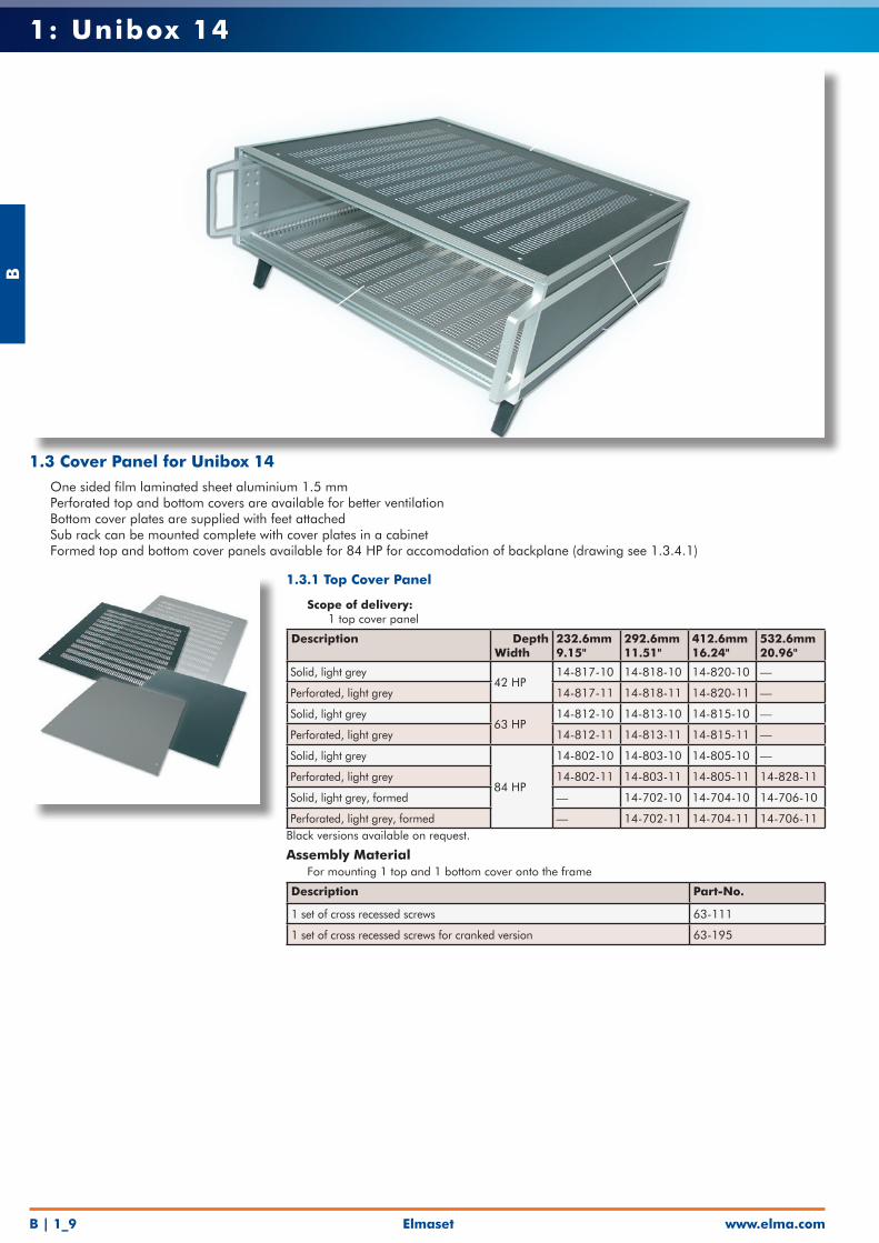
1.3 Cover Panel for Unibox 14• One sided film laminated sheet aluminium 1.5 mm• Perforated top and bottom covers are available for better ventilation• Bottom cover plates are supplied with feet attached• Sub rack can be mounted complete with cover plates in a cabinet• Formed top and bottom cover panels available for 84 HP for accomodation of backplane (drawing see 1.3.4.1)
1.3.1 Top Cover Panel
• Scope of delivery: • 1 top cover panel
Description DepthWidth
232.6mm9.15"
292.6mm11.51"
412.6mm16.24"
532.6mm20.96"
Solid, light grey42 HP
14-817-10 14-818-10 14-820-10 —
Perforated, light grey 14-817-11 14-818-11 14-820-11 —
Solid, light grey63 HP
14-812-10 14-813-10 14-815-10 —
Perforated, light grey 14-812-11 14-813-11 14-815-11 —
Solid, light grey
84 HP
14-802-10 14-803-10 14-805-10 —
Perforated, light grey 14-802-11 14-803-11 14-805-11 14-828-11
Solid, light grey, formed — 14-702-10 14-704-10 14-706-10
Perforated, light grey, formed — 14-702-11 14-704-11 14-706-11Black versions available on request.
Assembly Material• For mounting 1 top and 1 bottom cover onto the frame
Description Part-No.
1 set of cross recessed screws 63-111
1 set of cross recessed screws for cranked version 63-195
Elmaset
B
www.elma.com B | 1_10
1: Unibox 14
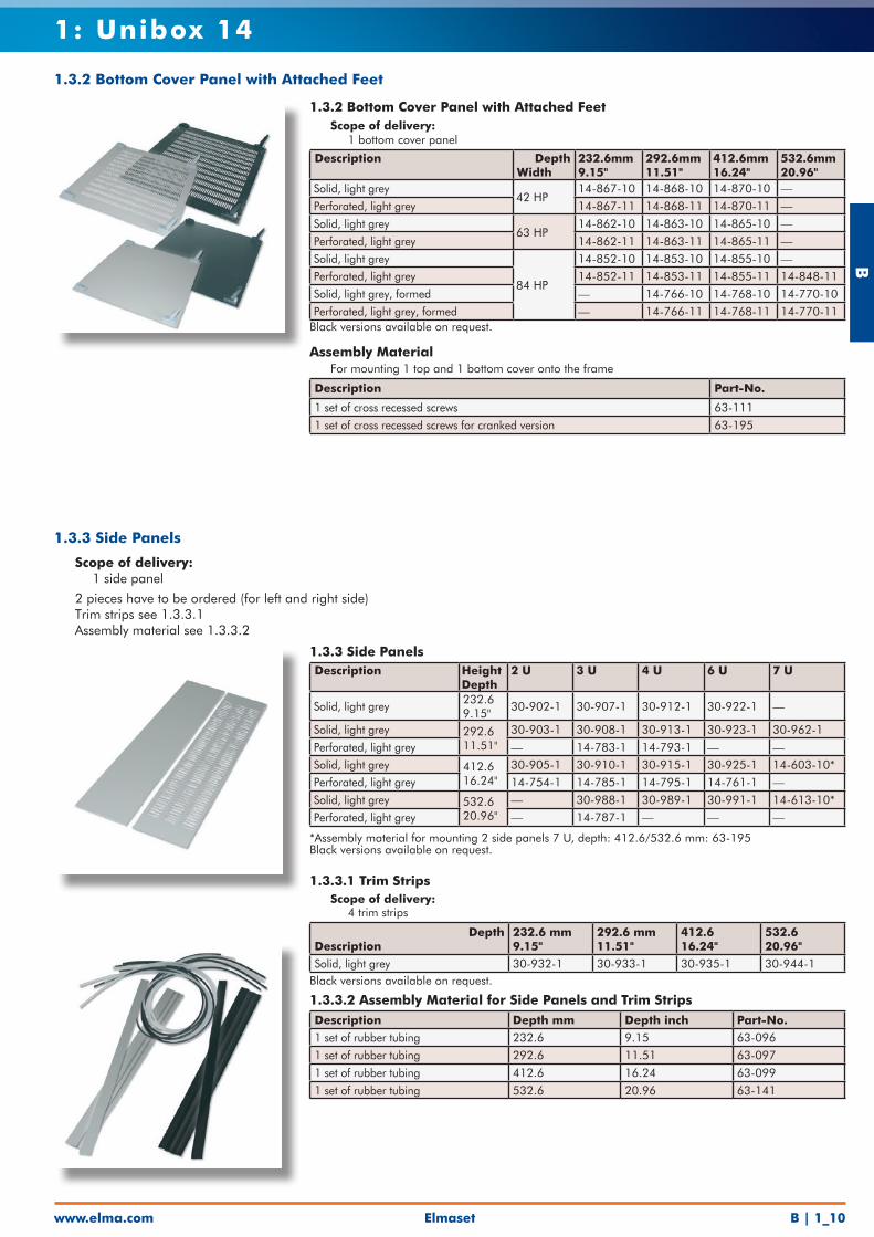
1.3.2 Bottom Cover Panel with Attached Feet• Scope of delivery: • 1 bottom cover panel
Description DepthWidth
232.6mm9.15"
292.6mm11.51"
412.6mm16.24"
532.6mm20.96"
Solid, light grey42 HP
14-867-10 14-868-10 14-870-10 —Perforated, light grey 14-867-11 14-868-11 14-870-11 —Solid, light grey
63 HP14-862-10 14-863-10 14-865-10 —
Perforated, light grey 14-862-11 14-863-11 14-865-11 —Solid, light grey
84 HP
14-852-10 14-853-10 14-855-10 —Perforated, light grey 14-852-11 14-853-11 14-855-11 14-848-11Solid, light grey, formed — 14-766-10 14-768-10 14-770-10Perforated, light grey, formed — 14-766-11 14-768-11 14-770-11
Black versions available on request.
Assembly Material• For mounting 1 top and 1 bottom cover onto the frame
Description Part-No.
1 set of cross recessed screws 63-1111 set of cross recessed screws for cranked version 63-195
1.3.3 Side Panels
• Scope of delivery: • 1 side panel
• 2 pieces have to be ordered (for left and right side)• Trim strips see 1.3.3.1• Assembly material see 1.3.3.2
1.3.3 Side PanelsDescription Height
Depth2 U 3 U 4 U 6 U 7 U
Solid, light grey232.69.15"
30-902-1 30-907-1 30-912-1 30-922-1 —
Solid, light grey 292.611.51"
30-903-1 30-908-1 30-913-1 30-923-1 30-962-1Perforated, light grey — 14-783-1 14-793-1 — —Solid, light grey 412.6
16.24"30-905-1 30-910-1 30-915-1 30-925-1 14-603-10*
Perforated, light grey 14-754-1 14-785-1 14-795-1 14-761-1 —Solid, light grey 532.6
20.96"— 30-988-1 30-989-1 30-991-1 14-613-10*
Perforated, light grey — 14-787-1 — — —
*Assembly material for mounting 2 side panels 7 U, depth: 412.6/532.6 mm: 63-195Black versions available on request.
1.3.3.1 Trim Strips• Scope of delivery: • 4 trim strips
DepthDescription
232.6 mm9.15"
292.6 mm11.51"
412.616.24"
532.620.96"
Solid, light grey 30-932-1 30-933-1 30-935-1 30-944-1Black versions available on request.
1.3.3.2 Assembly Material for Side Panels and Trim StripsDescription Depth mm Depth inch Part-No.1 set of rubber tubing 232.6 9.15 63-0961 set of rubber tubing 292.6 11.51 63-0971 set of rubber tubing 412.6 16.24 63-0991 set of rubber tubing 532.6 20.96 63-141
1.3.2 Bottom Cover Panel with Attached Feet
B
www.elma.comElmasetB | 1_11
1: Unibox 14
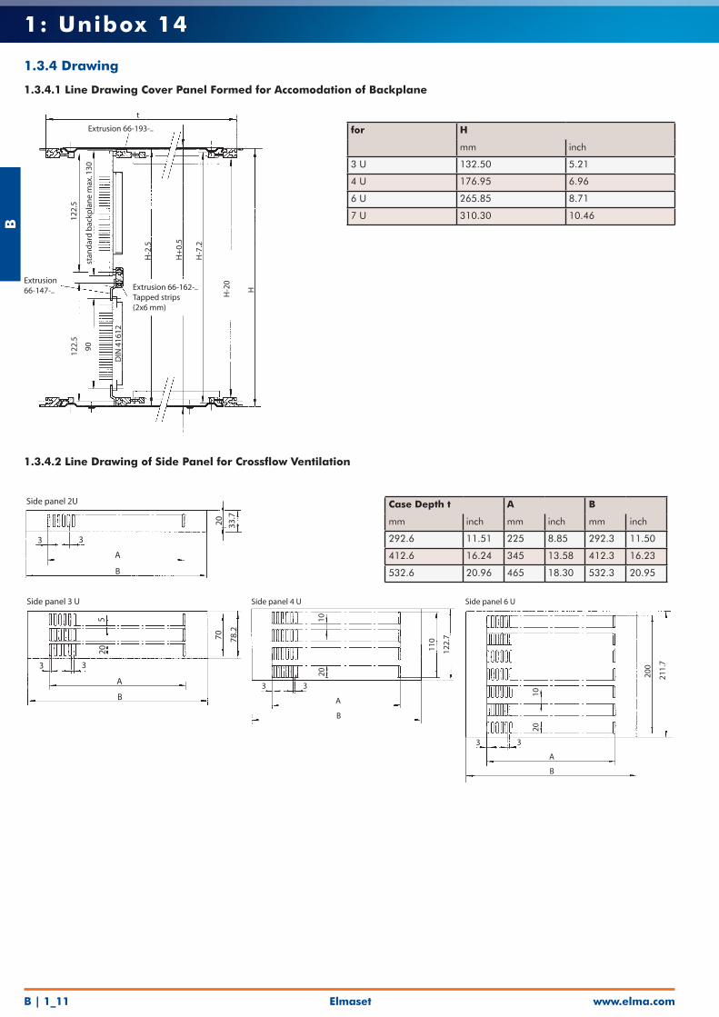
for H
mm inch
3 U 132.50 5.21
4 U 176.95 6.96
6 U 265.85 8.71
7 U 310.30 10.46
t
Extrusion 66-193-..
Extrusion66-147-.. Extrusion 66-162-..
Tapped strips(2x6 mm)
122.
512
2.5
90st
and
ard
bac
kpla
ne
max
. 130
H-2
.5
H+
0.5
H-7
.2
H-2
0
H
DIN
416
12
Case Depth t A B
mm inch mm inch mm inch
292.6 11.51 225 8.85 292.3 11.50
412.6 16.24 345 13.58 412.3 16.23
532.6 20.96 465 18.30 532.3 20.95
3 3
A
B
20 33.7
Side panel 2U
3 3
A
B
1020
110
122.
7
Side panel 4 U
3 3
A
B
2010
200
211.
7
Side panel 6 U
3 3
A
B
205
70 78.2
Side panel 3 U
1.3.4 Drawing
1.3.4.1 Line Drawing Cover Panel Formed for Accomodation of Backplane
1.3.4.2 Line Drawing of Side Panel for Crossflow Ventilation
Elmaset
B
www.elma.com B | 1_12
1: Unibox 14
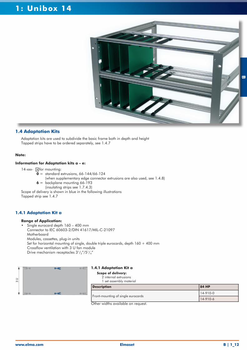
1.4 Adaptation Kits• Adaptation kits are used to subdivide the basic frame both in depth and height• Tapped strips have to be ordered separately, see 1.4.7
1.4.1 Adaptation Kit a• Scope of delivery: • 2 internal extrusions • 1 set assembly material
Description 84 HP
Front-mounting of single eurocards14-910-0
14-910-6Other widths available on request.
Information for Adaptation kits a - e:
• 14-xxx- x for mounting: 0 = standard extrusions, 66-144/66-124 (when supplementary edge connector extrusions are also used, see 1.4.8) 6 = backplane mounting 66-193 (insulating strips see 1.7.4.3)• Scope of delivery is shown in blue in the following illustrations• Tapped strip see 1.4.7
3 U
Note:
1.4.1 Adaptation Kit a
• Range of Application: • Single eurocard depth 160 – 400 mm • Connector to IEC 60603-2/DIN 41617/MIL-C-21097 • Motherboard • Modules, cassettes, plug-in units • Set for horizontal mounting of single, double triple eurocards, depth 160 + 400 mm • Crossflow ventilation with 3 U fan module • Drive mechanism receptacles 31/2”/51/4”
B
www.elma.comElmasetB | 1_13
1: Unibox 14
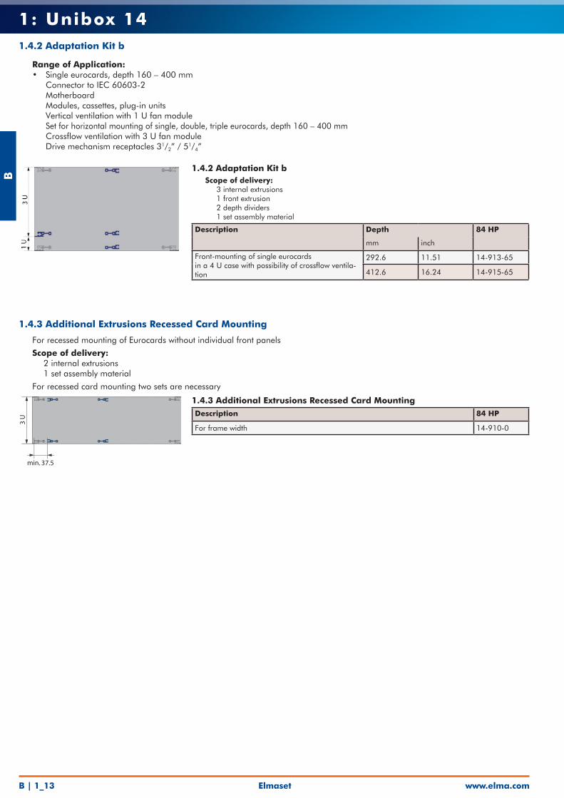
1.4.2 Adaptation Kit b• Scope of delivery: • 3 internal extrusions • 1 front extrusion • 2 depth dividers • 1 set assembly material
Description Depth 84 HP
mm inch
Front-mounting of single eurocards in a 4 U case with possibility of crossflow ventila-tion
292.6 11.51 14-913-65
412.6 16.24 14-915-65
1.4.2 Adaptation Kit b
• Range of Application: • Single eurocards, depth 160 – 400 mm • Connector to IEC 60603-2 • Motherboard • Modules, cassettes, plug-in units • Vertical ventilation with 1 U fan module • Set for horizontal mounting of single, double, triple eurocards, depth 160 – 400 mm • Crossflow ventilation with 3 U fan module • Drive mechanism receptacles 31/2” / 51/4”
1.4.3 Additional Extrusions Recessed Card MountingDescription 84 HP
For frame width 14-910-0
3 U
min. 37.5
1.4.3 Additional Extrusions Recessed Card Mounting
• For recessed mounting of Eurocards without individual front panels
• Scope of delivery: • 2 internal extrusions • 1 set assembly material
• For recessed card mounting two sets are necessary
Elmaset
B
www.elma.com B | 1_14
1: Unibox 14
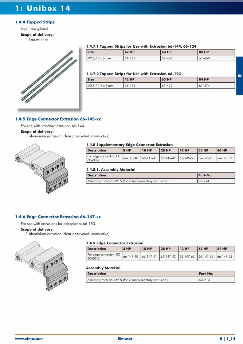
1.4.8 Supplementary Edge Connector Extrusion Description 8 HP 18 HP 28 HP 42 HP 63 HP 84 HP
For edge connector, IEC 60603-2
66-145-40 66-145-41 66-145-42 66-145-63 66-145-65 66-145-52
1.4.8.1. Assembly MaterialDescription Part-No.
Assembly material M2.5 (for 2 supplementary extrusions) 63-214
1.4.5 Edge Connector Extrusion 66-145-xx
• For use with standard extrusion 66-144
• Scope of delivery: • 1 aluminium extrusion, clear passivated (conductive)
1.4.9 Edge Connector ExtrusionDescription 8 HP 18 HP 28 HP 42 HP 63 HP 84 HP
For edge connector, IEC 60603-2
66-147-40 66-147-41 66-147-42 66-147-63 66-147-65 66-147-52
Assembly MaterialDescription Part-No.
Assembly material M2.5 (for 2 supplementary extrusions) 63-214
1.4.6 Edge Connector Extrusion 66-147-xx
• For use with extrusions for backplanes 66-193
• Scope of delivery: • 1 aluminium extrusion, clear passivated (conductive)
1.4.7.1 Tapped Strips for Use with Extrusion 66-144, 66-124Size 42 HP 63 HP 84 HP
M2.5 / 2 x 6 mm 61-464 61-469 61-468
1.4.7.2 Tapped Strips for Use with Extrusion 66-193Size 42 HP 63 HP 84 HP
M2.5 / 1.8 x 5 mm 61-471 61-472 61-474
1.4.4 Tapped Strips
• Steel, zinc-plated
• Scope of delivery: • 1 tapped strip
B
www.elma.comElmasetB | 1_15
1: Unibox 14
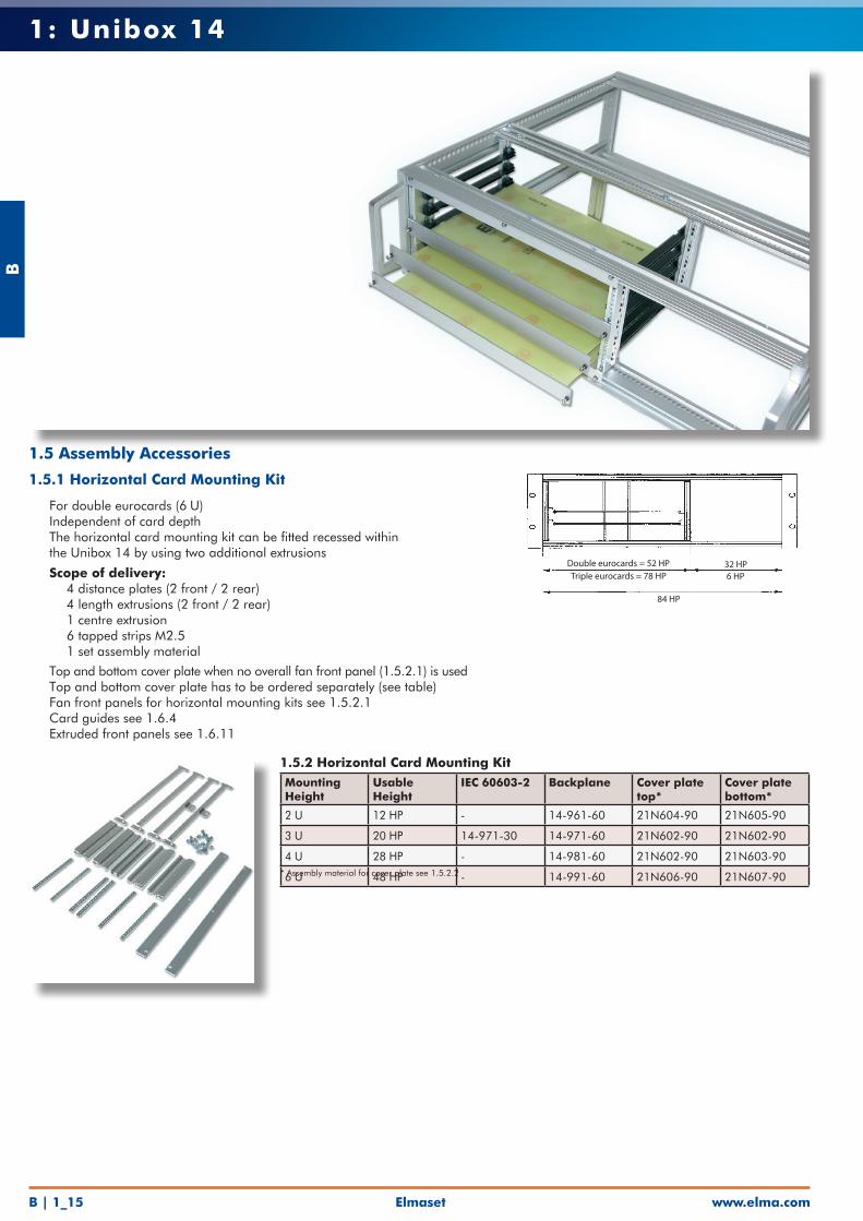
1.5.2 Horizontal Card Mounting KitMounting Height
Usable Height
IEC 60603-2 Backplane Cover plate top*
Cover plate bottom*
2 U 12 HP - 14-961-60 21N604-90 21N605-90
3 U 20 HP 14-971-30 14-971-60 21N602-90 21N602-90
4 U 28 HP - 14-981-60 21N602-90 21N603-90
6 U 48 HP - 14-991-60 21N606-90 21N607-90
* Assembly material for cover plate see 1.5.2.2
1.5 Assembly Accessories
1.5.1 Horizontal Card Mounting Kit
• For double eurocards (6 U)• Independent of card depth• The horizontal card mounting kit can be fitted recessed within the Unibox 14 by using two additional extrusions
• Scope of delivery: • 4 distance plates (2 front / 2 rear) • 4 length extrusions (2 front / 2 rear) • 1 centre extrusion • 6 tapped strips M2.5 • 1 set assembly material
• Top and bottom cover plate when no overall fan front panel (1.5.2.1) is used• Top and bottom cover plate has to be ordered separately (see table)• Fan front panels for horizontal mounting kits see 1.5.2.1• Card guides see 1.6.4• Extruded front panels see 1.6.11
Double eurocards = 52 HP
84 HP
Triple eurocards = 78 HP32 HP6 HP
Elmaset
B
www.elma.com B | 1_16
1: Unibox 14
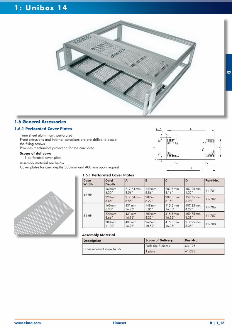
1.6.1 Perforated Cover PlatesCase Width
Card Depth
A B C D Part-No.
42 HP
160 mm 6.30”
217.64 mm 8.56”
149 mm 5.86”
207.5 mm 8.16”
107.25 mm 4.22”
11-701
220 mm 8.66”
217.64 mm 8.56”
209 mm 8.22”
207.5 mm 8.16”
159.75 mm 6.28”
11-702
84 HP
160 mm 6.30”
431 mm 16.96”
149 mm 5.86”
415.5 mm 16.35”
107.25 mm 4.22”
11-706
220 mm 8.66”
431 mm 16.96”
209 mm 8.22”
415.5 mm 16.35”
159.75 mm 6.28”
11-707
280 mm 11.02”
431 mm 16.96”
269 mm 10.59”
415.5 mm 16.35”
212.25 mm 8.35”
11-708
Assembly Material
Description Scope of Delivery Part-No.
Cross recessed screw M3x6Pack size 8 pieces 63-195
1 piece 61-283
1.6 General Accessories
1.6.1 Perforated Cover Plates
• 1mm sheet aluminium, perforated• Front extrusions and internal extrusions are pre-drilled to accept the fixing screws• Provides mechanical protection for the card area
• Scope of delivery: • 1 perforated cover plate
• Assembly material see below• Cover plates for card depths 300 mm and 400 mm upon request
B
www.elma.comElmasetB | 1_17
1: Unibox 14
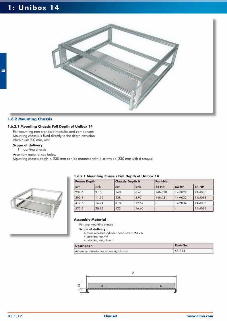
1.6.2.1 Mounting Chassis Full Depth of Unibox 14Frame Depth Chassis Depth A Part-No.
mm inch mm inch 42 HP 63 HP 84 HP
232.6 9.15 168 6.61 14M028 14M029 14M030
292.6 11.52 228 8.97 14M031 14M032 14M033
412.6 16.24 318 12.52 - 14M034 14M035
532.6 20.96 423 16.65 - - 14M036
Assembly Material• For one mounting chassis
• Scope of delivery: • 4 cross recessed cylinder head screw M4 x 6 • 4 earthing nut M4 • 4 retaining ring 2 mm
Description Part-No.
Assembly material for mounting chassis 63-314
1.6.2 Mounting Chassis
1.6.2.1 Mounting Chassis Full Depth of Unibox 14
• For mounting non-standard modules and components• Mounting chassis is fixed directly to the depth extrusion• Aluminium 2.0 mm, raw
• Scope of delivery: • 1 mounting chassis
• Assembly material see below• Mounting chassis depth < 230 mm can be mounted with 4 screws (> 230 mm with 6 screws)
A
10 1
4
Elmaset
B
www.elma.com B | 1_18
1: Unibox 14
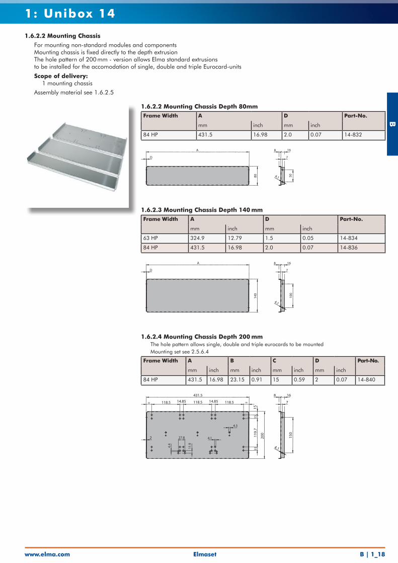
1.6.2.2 Mounting Chassis Depth 80mmFrame Width A D Part-No.
mm inch mm inch
84 HP 431.5 16.98 2.0 0.07 14-832
D
A
80
8 16
7
4.1 50
1.6.2.3 Mounting Chassis Depth 140 mmFrame Width A D Part-No.
mm inch mm inch
63 HP 324.9 12.79 1.5 0.05 14-834
84 HP 431.5 16.98 2.0 0.07 14-836
D
A
140
8 16
7
100
4.1
1.6.2.4 Mounting Chassis Depth 200 mm• The hole pattern allows single, double and triple eurocards to be mounted• Mounting set see 2.5.6.4
Frame Width A B C D Part-No.
mm inch mm inch mm inch mm inch
84 HP 431.5 16.98 23.15 0.91 15 0.59 2 0.07 14-840
431.5
= 118.5 14.85 118.5 14.85 118.5 =
15
15
119.
7
200
15
2 27.8
4.4
11.9
4.1
4.3
8 16
7
150
4.1
1.6.2.2 Mounting Chassis
• For mounting non-standard modules and components• Mounting chassis is fixed directly to the depth extrusion• The hole pattern of 200 mm - version allows Elma standard extrusions to be installed for the accomodation of single, double and triple Eurocard-units
• Scope of delivery: • 1 mounting chassis
• Assembly material see 1.6.2.5
B
www.elma.comElmasetB | 1_19
1: Unibox 14
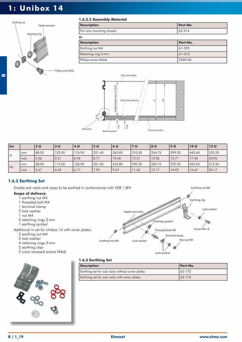
Earthing nut
Retaining ring
Depth extrusion
Philips screw M4x6
1.6.3 Earthing Set
• Enable sub racks and cases to be earthed in conformance with VDE / SEV
• Scope of delivery: • 1 earthing nut M4 • 1 threaded bolt M4 • 1 terminal clamp • 2 lock washer • 1 nut M4 • 2 retaining rings 2 mm • 1 earthing symbol
Additional in set for Unibox 14 with cover plates: • 2 earthing nut M4 • 2 lock washer • 4 retaining rings 2 mm • 2 earthing clips • 2 cross recessed screws M4x6
1.6.3 Earthing Set Description Part-No.
Earthing set for sub racks without cover plates 63-172
Earthing set for sub racks with cover plates 63-173
Depth extrusion
Earthing nut M4
Earthing clip
Lock washer
Screw M4 x 6
Earthing symbol
Threaded bolt M4
Terminal clamp
Hex nut M4Earthing nut M4 Lock washer
Lock washer
1.6.2.5 Assembly Material Description Part-No.
For one mounting chassis 63-314
or
Description Part-No.
Earthing nut M4 61-095
Retaining ring 2 mm 61-015
Philips screw M4x6 5340-06
for 2 U 3 U 4 U 5 U 6 U 7 U 8 U 9 U 10 U 12 U
Hmm 88.05 132.50 176.95 221.40 265.85 310.30 354.75 399.20 443.65 532.55
inch 3.46 5.21 6.96 8.71 10.46 12.21 13.96 15.71 17.46 20.96
Hsmm 68.05 112.50 156.95 201.40 245.85 290.30 334.75 379.20 423.65 512.55
inch 2.67 4.42 6.17 7.92 9.67 11.42 13.17 14.92 16.67 20.17
Top cover plate
Mounting chassis
usa
ble
hei
gh
t m
ax. (
H-1
8.5)
Bottom panel
14.9
(3.6
)
Front extrusionExtrusion
21.9
H Hs
Elmaset
B
www.elma.com B | 1_20
1: Unibox 14
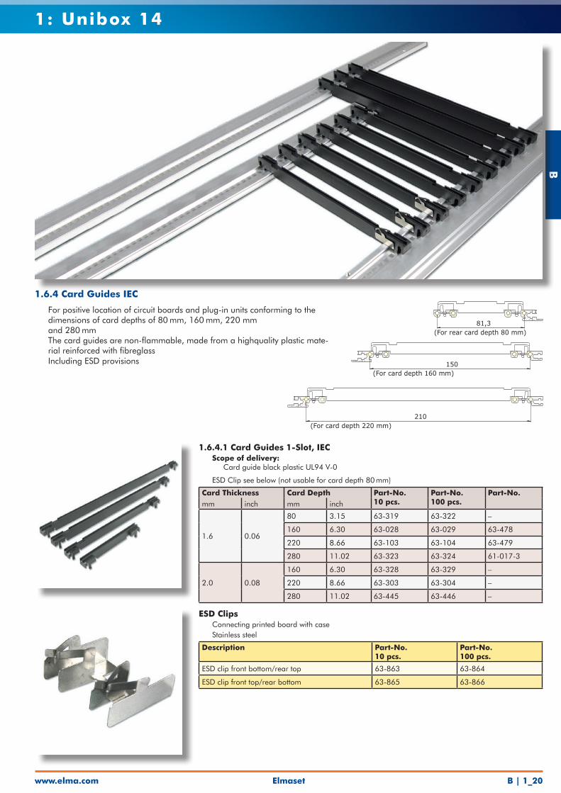
1.6.4.1 Card Guides 1-Slot, IEC• Scope of delivery: • Card guide black plastic UL94 V-0
• ESD Clip see below (not usable for card depth 80 mm)
Card Thickness Card Depth Part-No.10 pcs.
Part-No.100 pcs.
Part-No.mm inch mm inch
1.6 0.06
80 3.15 63-319 63-322 –
160 6.30 63-028 63-029 63-478
220 8.66 63-103 63-104 63-479
280 11.02 63-323 63-324 61-017-3
2.0 0.08
160 6.30 63-328 63-329 –
220 8.66 63-303 63-304 –
280 11.02 63-445 63-446 –
1.6.4 Card Guides IEC
• For positive location of circuit boards and plug-in units conforming to the dimensions of card depths of 80 mm, 160 mm, 220 mm
and 280 mm• The card guides are non-flammable, made from a highquality plastic mate-
rial reinforced with fibreglass• Including ESD provisions
ESD Clips• Connecting printed board with case• Stainless steel
Description Part-No.10 pcs.
Part-No.100 pcs.
ESD clip front bottom/rear top 63-863 63-864
ESD clip front top/rear bottom 63-865 63-866
210
150 81,3(For card depth 160 mm) (For rear card depth 80 mm)
(For card depth 220 mm)
210
150 81,3(For card depth 160 mm) (For rear card depth 80 mm)
(For card depth 220 mm)210
150 81,3(For card depth 160 mm) (For rear card depth 80 mm)
(For card depth 220 mm)
B
www.elma.comElmasetB | 1_21
1: Unibox 14
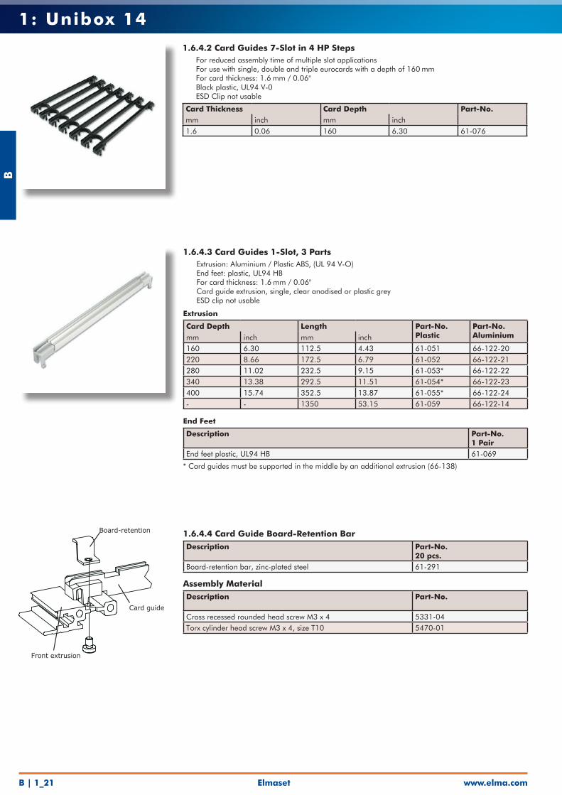
1.6.4.2 Card Guides 7-Slot in 4 HP Steps • For reduced assembly time of multiple slot applications• For use with single, double and triple eurocards with a depth of 160 mm• For card thickness: 1.6 mm / 0.06"• Black plastic, UL94 V-0• ESD Clip not usable
Card Thickness Card Depth Part-No.mm inch mm inch1.6 0.06 160 6.30 61-076
1.6.4.3 Card Guides 1-Slot, 3 Parts• Extrusion: Aluminium / Plastic ABS, (UL 94 V-O)• End feet: plastic, UL94 HB• For card thickness: 1.6 mm / 0.06"• Card guide extrusion, single, clear anodised or plastic grey• ESD clip not usable
Extrusion
Card Depth Length Part-No.Plastic
Part-No.Aluminiummm inch mm inch
160 6.30 112.5 4.43 61-051 66-122-20220 8.66 172.5 6.79 61-052 66-122-21280 11.02 232.5 9.15 61-053* 66-122-22340 13.38 292.5 11.51 61-054* 66-122-23400 15.74 352.5 13.87 61-055* 66-122-24- - 1350 53.15 61-059 66-122-14
End Feet
Description Part-No.1 Pair
End feet plastic, UL94 HB 61-069
* Card guides must be supported in the middle by an additional extrusion (66-138)
1.6.4.4 Card Guide Board-Retention BarDescription Part-No.
20 pcs.Board-retention bar, zinc-plated steel 61-291
Assembly MaterialDescription Part-No.
Cross recessed rounded head screw M3 x 4 5331-04Torx cylinder head screw M3 x 4, size T10 5470-01
Board-retention
Card guide
Front extrusion
Elmaset
B
www.elma.com B | 1_22
1: Unibox 14
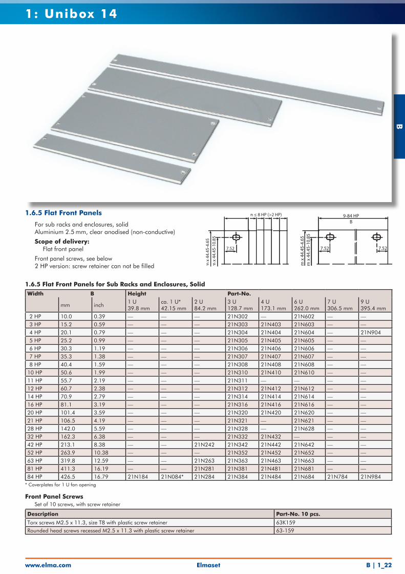
1.6.5 Flat Front Panels for Sub Racks and Enclosures, SolidWidth B Height Part-No.
mm inch1 U39.8 mm
ca. 1 U*42.15 mm
2 U84.2 mm
3 U128.7 mm
4 U173.1 mm
6 U262.0 mm
7 U306.5 mm
9 U395.4 mm
2 HP 10.0 0.39 — — — 21N302 — 21N602 — — 3 HP 15.2 0.59 — — — 21N303 21N403 21N603 — — 4 HP 20.1 0.79 — — — 21N304 21N404 21N604 — 21N904 5 HP 25.2 0.99 — — — 21N305 21N405 21N605 — — 6 HP 30.3 1.19 — — — 21N306 21N406 21N606 — — 7 HP 35.3 1.38 — — — 21N307 21N407 21N607 — — 8 HP 40.4 1.59 — — — 21N308 21N408 21N608 — — 10 HP 50.6 1.99 — — — 21N310 21N410 21N610 — — 11 HP 55.7 2.19 — — — 21N311 — — — — 12 HP 60.7 2.38 — — — 21N312 21N412 21N612 — — 14 HP 70.9 2.79 — — — 21N314 21N414 21N614 — — 16 HP 81.1 3.19 — — — 21N316 21N416 21N616 — — 20 HP 101.4 3.59 — — — 21N320 21N420 21N620 — — 21 HP 106.5 4.19 — — — 21N321 — 21N621 — — 28 HP 142.0 5.59 — — — 21N328 — 21N628 — — 32 HP 162.3 6.38 — — — 21N332 21N432 — — —42 HP 213.1 8.38 — — 21N242 21N342 21N442 21N642 — —52 HP 263.9 10.38 — — — 21N352 21N452 21N652 — —63 HP 319.8 12.59 — — 21N263 21N363 21N463 21N663 — —81 HP 411.3 16.19 — — 21N281 21N381 21N481 21N681 — —84 HP 426.5 16.79 21N184 21N084* 21N284 21N384 21N484 21N684 21N784 21N984
* Coverplates for 1 U fan opening
Front Panel Screws• Set of 10 screws, with screw retainer
Description Part-No. 10 pcs.
Torx screws M2.5 x 11.3, size T8 with plastic screw retainer 63K159Rounded head screws recessed M2.5 x 11.3 with plastic screw retainer 63-159
m x
44.
45-4
.65
m x
44.
45-1
0.85
7.52 7.52
9-84 HPB
m x
44.
45-4
.65
m x
44.
45-1
0.85
7.52
n ≤ 8 HP (>2 HP)1.6.5 Flat Front Panels
• For sub racks and enclosures, solid• Aluminium 2.5 mm, clear anodised (non-conductive)
• Scope of delivery: • Flat front panel
• Front panel screws, see below• 2 HP version: screw retainer can not be filled
B
www.elma.comElmasetB | 1_23
1: Unibox 14
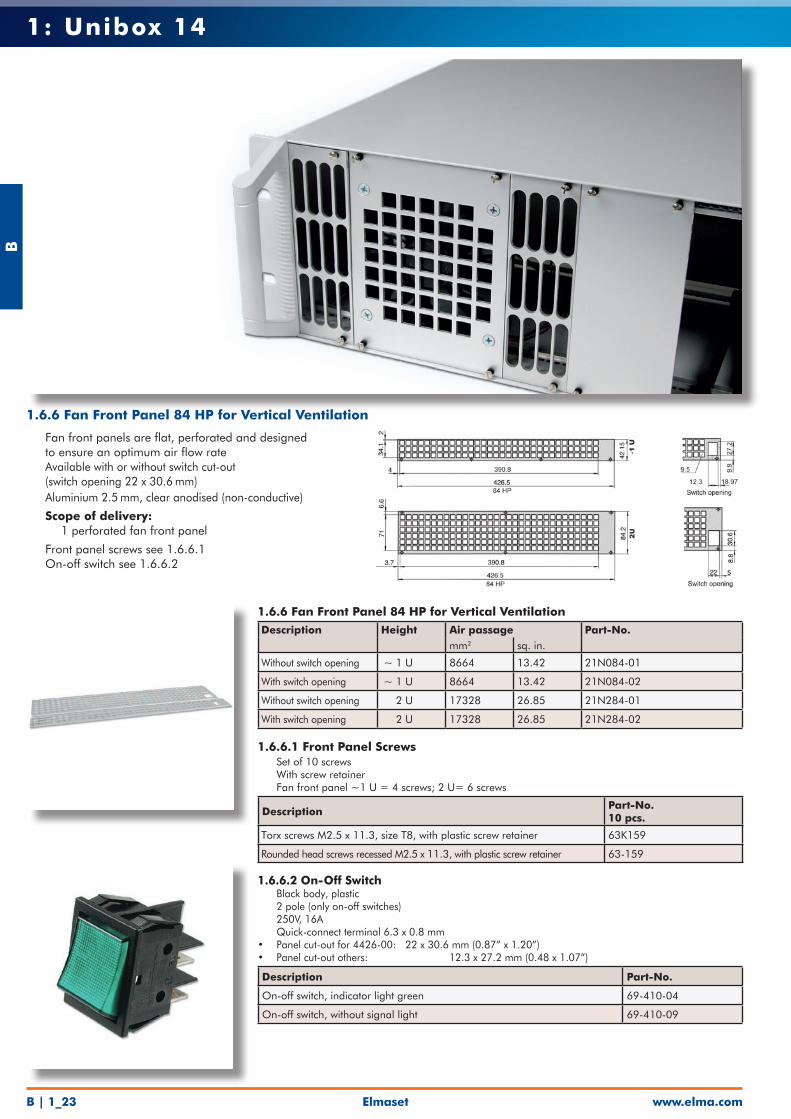
1.6.6 Fan Front Panel 84 HP for Vertical VentilationDescription Height Air passage Part-No.
mm2 sq. in.
Without switch opening ~ 1 U 8664 13.42 21N084-01
With switch opening ~ 1 U 8664 13.42 21N084-02
Without switch opening 2 U 17328 26.85 21N284-01
With switch opening 2 U 17328 26.85 21N284-02
1.6.6.1 Front Panel Screws• Set of 10 screws• With screw retainer• Fan front panel ~1 U = 4 screws; 2 U= 6 screws
Description Part-No. 10 pcs.
Torx screws M2.5 x 11.3, size T8, with plastic screw retainer 63K159
Rounded head screws recessed M2.5 x 11.3, with plastic screw retainer 63-159
1.6.6.2 On-Off Switch• Black body, plastic• 2 pole (only on-off switches)• 250V, 16A• Quick-connect terminal 6.3 x 0.8 mm• Panel cut-out for 4426-00: 22 x 30.6 mm (0.87” x 1.20”) • Panel cut-out others: 12.3 x 27.2 mm (0.48 x 1.07”)
Description Part-No.
On-off switch, indicator light green 69-410-04
On-off switch, without signal light 69-410-09
1.6.6 Fan Front Panel 84 HP for Vertical Ventilation
• Fan front panels are flat, perforated and designed to ensure an optimum air flow rate
• Available with or without switch cut-out (switch opening 22 x 30.6 mm)
• Aluminium 2.5 mm, clear anodised (non-conductive)
• Scope of delivery: • 1 perforated fan front panel
• Front panel screws see 1.6.6.1• On-off switch see 1.6.6.2
Elmaset
B
www.elma.com B | 1_24
1: Unibox 14
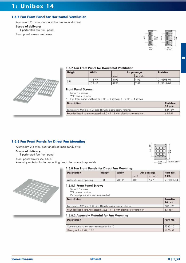
1.6.7 Fan Front Panel for Horizontal VentilationHeight Width Air passage Part-No.
mm2 sq. inch
3 U 8 HP 3195 4.95 21N308-01 12 HP 4793 7.42 21N312-01
Front Panel Screws• Set of 10 screws• With screw retainer• Fan front panel width up to 8 HP = 2 screws; ≥ 12 HP = 4 screws
Description Part-No. 10 pcs.
Torx screws M2.5 x 11.3, size T8 with plastic screw retainer 63K159Rounded head screws recessed M2.5 x 11.3 with plastic screw retainer 63-159
1.6.7 Fan Front Panel for Horizontal Ventilation
• Aluminium 2.5 mm, clear anodised (non-conductive)
• Scope of delivery: • 1 perforated fan front panel
• Front panel screws see below
1.6.8 Fan Front Panels for Direct Fan MountingDescription Height Width Air passage Part-No.
1 pc.mm2 sq. inchWithout switch opening 3 U 20 HP 4051 6.27 21N320-04
1.6.8.1 Front Panel Screws• Set of 10 screws• With screw retainer• Per front panel 4 screws are needed
Description Part-No. 10 pcs.
Torx screws M2.5 x 11.3, size T8 with plastic screw retainer 63K159Rounded head screws recessed M2.5 x 11.3 with plastic screw retainer 63-159
1.6.8.2 Assembly Material for Fan MountingDescription Part-No.
Countersunk screw, cross recessed M4 x 10 5342-10Hexagonal nut M4, 0.8D 5620-51
1.6.8 Fan Front Panels for Direct Fan Mounting
• Aluminium 2.5 mm, clear anodised (non-conductive)
• Scope of delivery: • 1 perforated fan front panel
• Front panel screws see 1.6.8.1• Assembly material for fan mounting has to be ordered separately
B
www.elma.comElmasetB | 1_25
1: Unibox 14
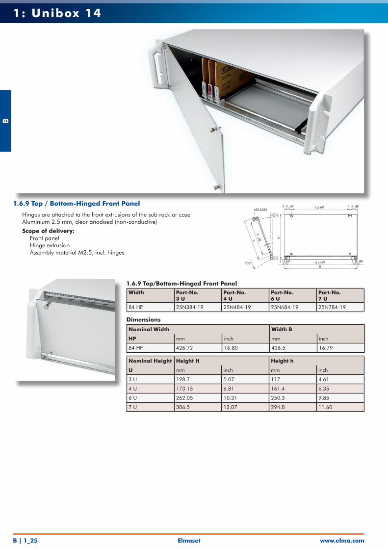
1.6.9 Top/Bottom-Hinged Front PanelWidth Part-No.
3 UPart-No. 4 U
Part-No. 6 U
Part-No. 7 U
84 HP 25N384-19 25N484-19 25N684-19 25N784-19
Dimensions
Nominal Width Width B
HP mm inch mm inch
84 HP 426.72 16.80 426.5 16.79
Nominal Height Height H Height h
U mm inch mm inch
3 U 128.7 5.07 117 4.61
4 U 173.15 6.81 161.4 6.35
6 U 262.05 10.31 250.3 9.85
7 U 306.5 12.07 294.8 11.60
1.6.9 Top / Bottom-Hinged Front Panel
• Hinges are attached to the front extrusions of the sub rack or case• Aluminium 2.5 mm, clear anodised (non-conductive)
• Scope of delivery: • Front panel • Hinge extrusion • Assembly material M2.5, incl. hinges
Elmaset
B
www.elma.com B | 1_26
1: Unibox 14
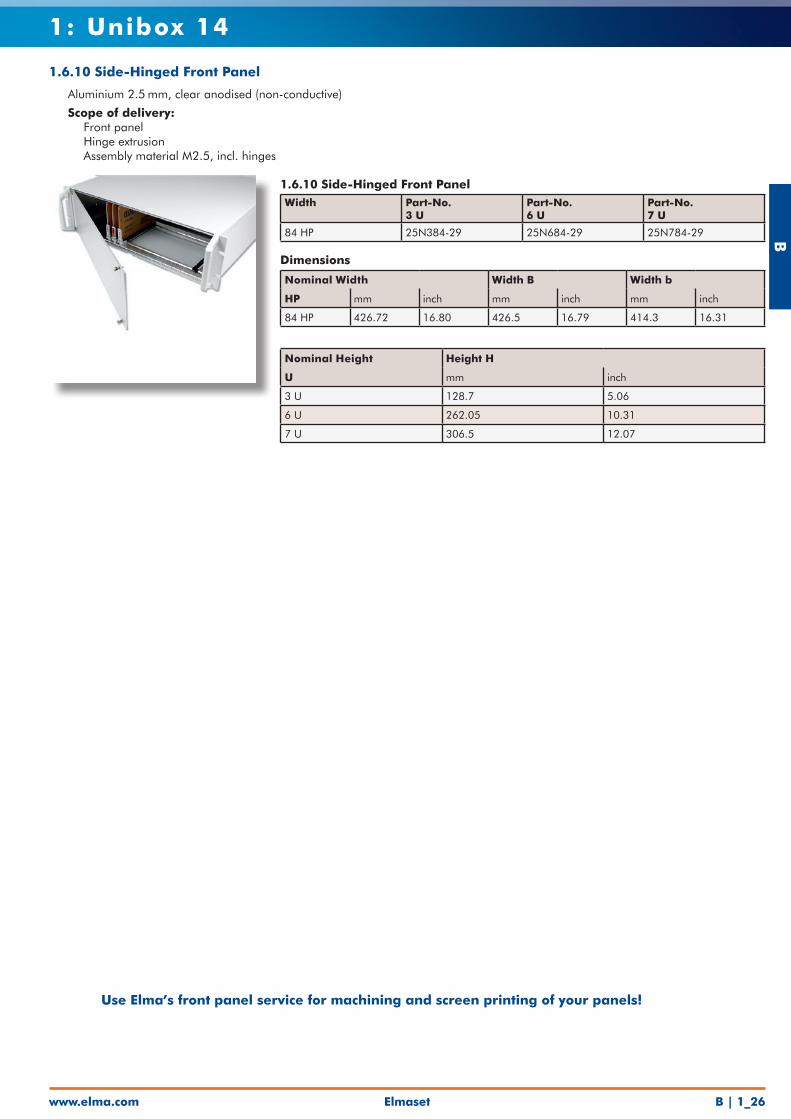
1.6.10 Side-Hinged Front PanelWidth Part-No.
3 UPart-No. 6 U
Part-No. 7 U
84 HP 25N384-29 25N684-29 25N784-29
Dimensions
Nominal Width Width B Width b
HP mm inch mm inch mm inch
84 HP 426.72 16.80 426.5 16.79 414.3 16.31
Nominal Height Height H
U mm inch
3 U 128.7 5.06
6 U 262.05 10.31
7 U 306.5 12.07
1.6.10 Side-Hinged Front Panel
• Aluminium 2.5 mm, clear anodised (non-conductive)
• Scope of delivery: • Front panel • Hinge extrusion • Assembly material M2.5, incl. hinges
Use Elma’s front panel service for machining and screen printing of your panels!
B
www.elma.comElmasetB | 1_27
1: Unibox 14
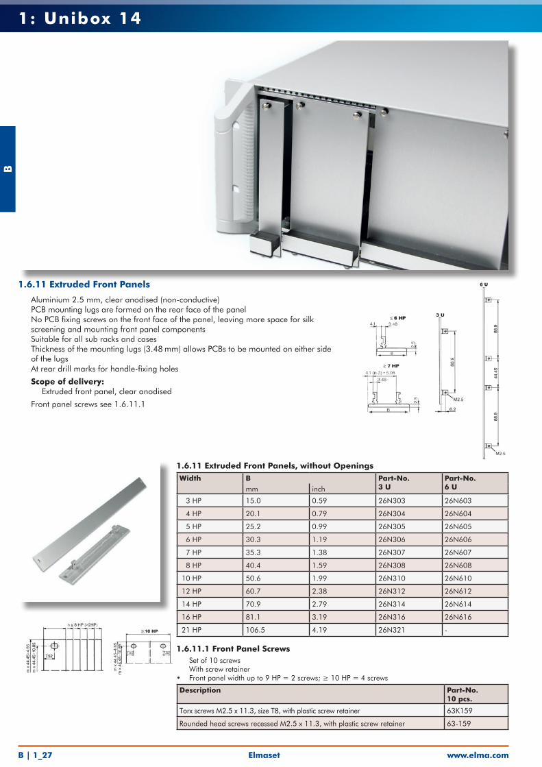
1.6.11 Extruded Front Panels, without OpeningsWidth B Part-No.
3 UPart-No. 6 Umm inch
3 HP 15.0 0.59 26N303 26N603
4 HP 20.1 0.79 26N304 26N604
5 HP 25.2 0.99 26N305 26N605
6 HP 30.3 1.19 26N306 26N606
7 HP 35.3 1.38 26N307 26N607
8 HP 40.4 1.59 26N308 26N608
10 HP 50.6 1.99 26N310 26N610
12 HP 60.7 2.38 26N312 26N612
14 HP 70.9 2.79 26N314 26N614
16 HP 81.1 3.19 26N316 26N616
21 HP 106.5 4.19 26N321 -
1.6.11.1 Front Panel Screws• Set of 10 screws• With screw retainer• Front panel width up to 9 HP = 2 screws; ≥ 10 HP = 4 screws
Description Part-No.10 pcs.
Torx screws M2.5 x 11.3, size T8, with plastic screw retainer 63K159
Rounded head screws recessed M2.5 x 11.3, with plastic screw retainer 63-159
1.6.11 Extruded Front Panels
• Aluminium 2.5 mm, clear anodised (non-conductive)• PCB mounting lugs are formed on the rear face of the panel• No PCB fixing screws on the front face of the panel, leaving more space for silk
screening and mounting front panel components• Suitable for all sub racks and cases• Thickness of the mounting lugs (3.48 mm) allows PCBs to be mounted on either side
of the lugs• At rear drill marks for handle-fixing holes
• Scope of delivery: • Extruded front panel, clear anodised
• Front panel screws see 1.6.11.1
Elmaset
B
www.elma.com B | 1_28
1: Unibox 14
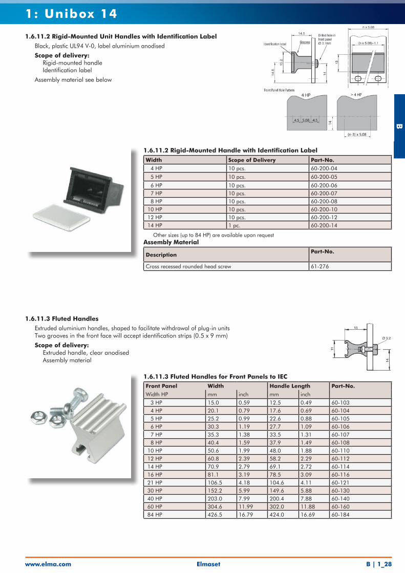
1.6.11.2 Rigid-Mounted Handle with Identification Label
Width Scope of Delivery Part-No.
4 HP 10 pcs. 60-200-04
5 HP 10 pcs. 60-200-05
6 HP 10 pcs. 60-200-06 7 HP 10 pcs. 60-200-07 8 HP 10 pcs. 60-200-08 10 HP 10 pcs. 60-200-10 12 HP 10 pcs. 60-200-12 14 HP 1 pc. 60-200-14
• Other sizes (up to 84 HP) are available upon requestAssembly Material
DescriptionPart-No.
Cross recessed rounded head screw 61-276
1.6.11.2 Rigid-Mounted Unit Handles with Identification Label
• Black, plastic UL94 V-0, label aluminium anodised
• Scope of delivery: • Rigid-mounted handle • Identification label
• Assembly material see below
1.6.11.3 Fluted Handles for Front Panels to IEC Front Panel Width Handle Length Part-No.
Width HP mm inch mm inch
3 HP 15.0 0.59 12.5 0.49 60-103 4 HP 20.1 0.79 17.6 0.69 60-104 5 HP 25.2 0.99 22.6 0.88 60-105 6 HP 30.3 1.19 27.7 1.09 60-106 7 HP 35.3 1.38 33.5 1.31 60-107 8 HP 40.4 1.59 37.9 1.49 60-108 10 HP 50.6 1.99 48.0 1.88 60-110 12 HP 60.8 2.39 58.2 2.29 60-112 14 HP 70.9 2.79 69.1 2.72 60-114 16 HP 81.1 3.19 78.5 3.09 60-116 21 HP 106.5 4.18 104.6 4.11 60-121 30 HP 152.2 5.99 149.6 5.88 60-130 40 HP 203.0 7.99 200.4 7.88 60-140 60 HP 304.6 11.99 302.0 11.88 60-160 84 HP 426.5 16.79 424.0 16.69 60-184
1.6.11.3 Fluted Handles
• Extruded aluminium handles, shaped to facilitate withdrawal of plug-in units• Two grooves in the front face will accept identification strips (0.5 x 9 mm)
• Scope of delivery: • Extruded handle, clear anodised • Assembly material
B
www.elma.comElmasetB | 1_29
1: Unibox 14
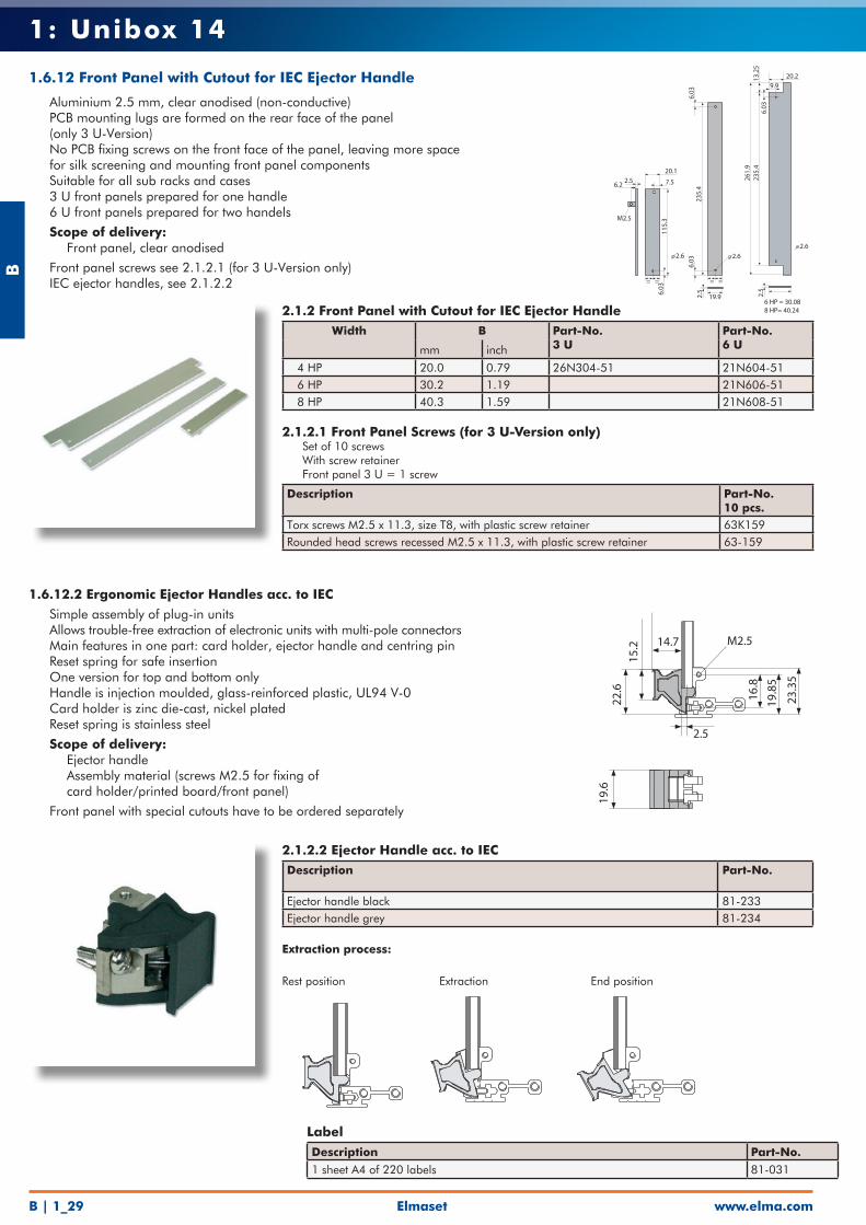
2.1.2.2 Ejector Handle acc. to IECDescription Part-No.
Ejector handle black 81-233Ejector handle grey 81-234
Extraction process:
Rest position Extraction End position
1.6.12.2 Ergonomic Ejector Handles acc. to IEC
• Simple assembly of plug-in units• Allows trouble-free extraction of electronic units with multi-pole connectors• Main features in one part: card holder, ejector handle and centring pin• Reset spring for safe insertion• One version for top and bottom only• Handle is injection moulded, glass-reinforced plastic, UL94 V-0• Card holder is zinc die-cast, nickel plated• Reset spring is stainless steel
• Scope of delivery: • Ejector handle • Assembly material (screws M2.5 for fixing of card holder/printed board/front panel)
• Front panel with special cutouts have to be ordered separately
2.1.2 Front Panel with Cutout for IEC Ejector HandleWidth B Part-No.
3 UPart-No. 6 Umm inch
4 HP 20.0 0.79 26N304-51 21N604-51 6 HP 30.2 1.19 21N606-51 8 HP 40.3 1.59 21N608-51
2.1.2.1 Front Panel Screws (for 3 U-Version only)• Set of 10 screws • With screw retainer• Front panel 3 U = 1 screw
Description Part-No.10 pcs.
Torx screws M2.5 x 11.3, size T8, with plastic screw retainer 63K159Rounded head screws recessed M2.5 x 11.3, with plastic screw retainer 63-159
2.5
2.6
6 HP = 30.088 HP= 40.24
20.2
9.9
6.03
235.
426
1.9
13.2
5
235.
4 6.
036.
03
2.5
2.6
19.9
= =
2.56.2
20.1
7.5
6.03
115.
3M2.5
= =
2.6
Label
Description Part-No.
1 sheet A4 of 220 labels 81-031
1.6.12 Front Panel with Cutout for IEC Ejector Handle
• Aluminium 2.5 mm, clear anodised (non-conductive)• PCB mounting lugs are formed on the rear face of the panel
(only 3 U-Version)• No PCB fixing screws on the front face of the panel, leaving more space
for silk screening and mounting front panel components• Suitable for all sub racks and cases• 3 U front panels prepared for one handle• 6 U front panels prepared for two handels
• Scope of delivery: • Front panel, clear anodised
• Front panel screws see 2.1.2.1 (for 3 U-Version only)• IEC ejector handles, see 2.1.2.2
19.6
22
.6
15.2
14.7
2.5
23.3
5
19.8
5
16.8
M2.5
Elmaset
B
www.elma.com B | 1_30
1: Unibox 14
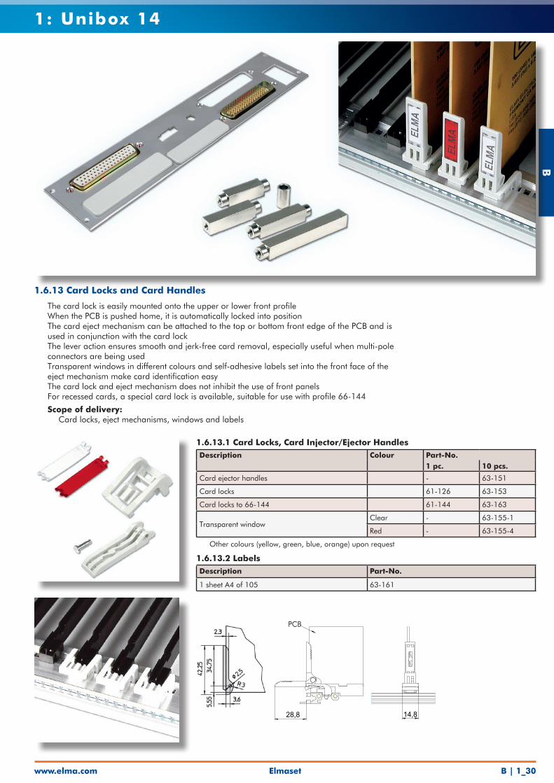
1.6.13.1 Card Locks, Card Injector/Ejector Handles Description Colour Part-No.
1 pc. 10 pcs.
Card ejector handles - 63-151
Card locks 61-126 63-153
Card locks to 66-144 61-144 63-163
Transparent windowClear - 63-155-1
Red - 63-155-4
• Other colours (yellow, green, blue, orange) upon request
1.6.13.2 LabelsDescription Part-No.
1 sheet A4 of 105 63-161
28,8 14,8
1.6.13 Card Locks and Card Handles
• The card lock is easily mounted onto the upper or lower front profile• When the PCB is pushed home, it is automatically locked into position• The card eject mechanism can be attached to the top or bottom front edge of the PCB and is
used in conjunction with the card lock• The lever action ensures smooth and jerk-free card removal, especially useful when multi-pole connectors are being used• Transparent windows in different colours and self-adhesive labels set into the front face of the
eject mechanism make card identification easy• The card lock and eject mechanism does not inhibit the use of front panels• For recessed cards, a special card lock is available, suitable for use with profile 66-144
• Scope of delivery: • Card locks, eject mechanisms, windows and labels
PCB
B
www.elma.comElmasetB | 1_31
1: Unibox 14
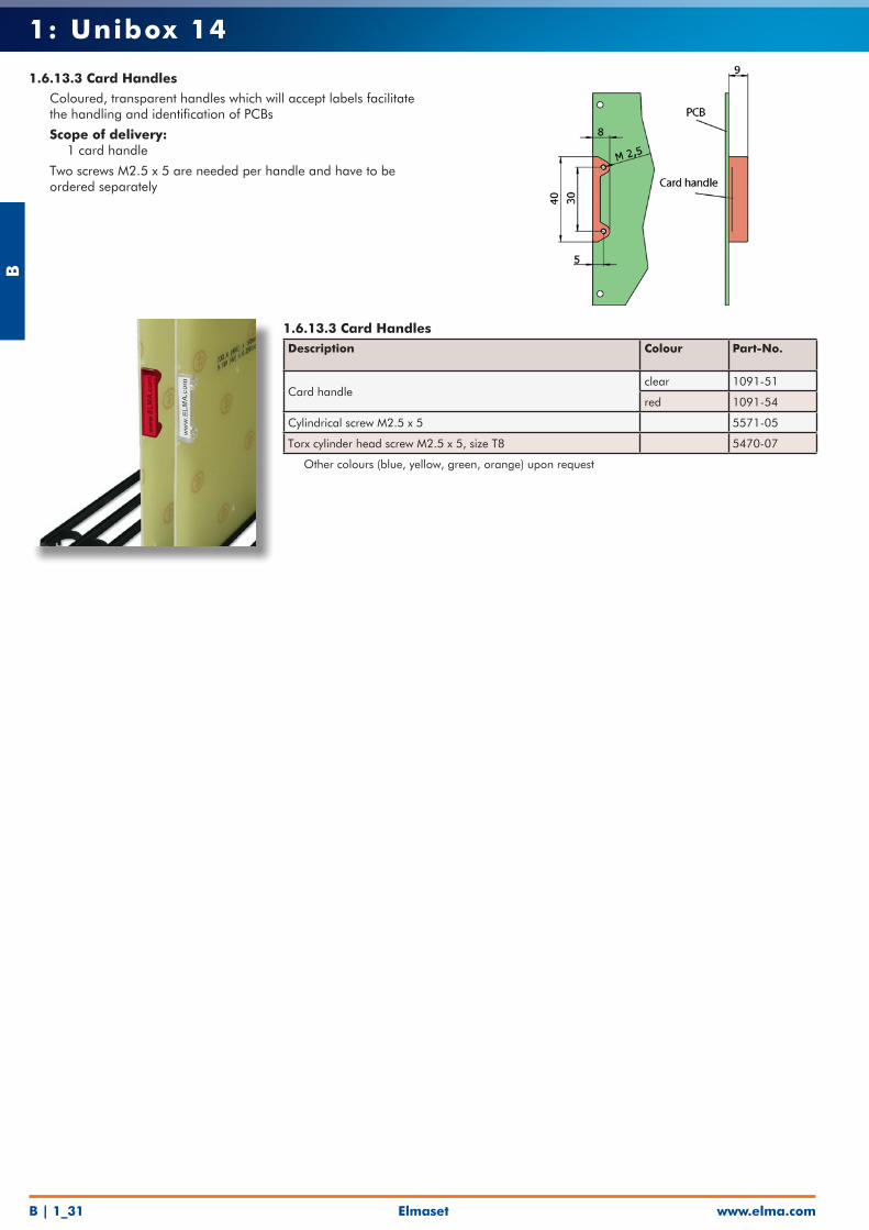
1.6.13.3 Card Handles
• Coloured, transparent handles which will accept labels facilitate the handling and identification of PCBs
• Scope of delivery: • 1 card handle
• Two screws M2.5 x 5 are needed per handle and have to be ordered separately
1.6.13.3 Card HandlesDescription Colour Part-No.
Card handleclear 1091-51
red 1091-54
Cylindrical screw M2.5 x 5 5571-05
Torx cylinder head screw M2.5 x 5, size T8 5470-07
• Other colours (blue, yellow, green, orange) upon request
Elmaset
B
www.elma.com B | 1_32
1: Unibox 14
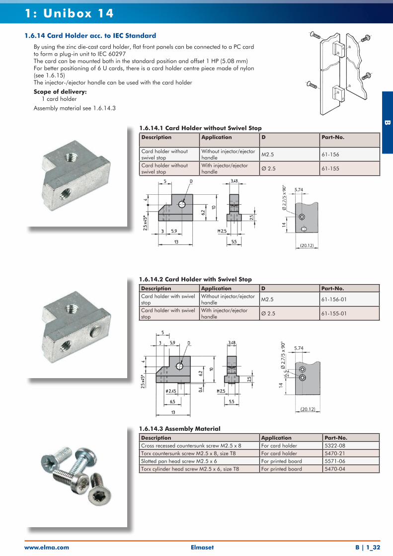
1.6.14 Card Holder acc. to IEC Standard
• By using the zinc die-cast card holder, flat front panels can be connected to a PC card to form a plug-in unit to IEC 60297
• The card can be mounted both in the standard position and offset 1 HP (5.08 mm)• For better positioning of 6 U cards, there is a card holder centre piece made of nylon
(see 1.6.15)• The injector-/ejector handle can be used with the card holder
• Scope of delivery: • 1 card holder
• Assembly material see 1.6.14.3
1.6.14.1 Card Holder without Swivel StopDescription Application D Part-No.
Card holder without swivel stop
Without injector/ejector handle
M2.5 61-156
Card holder without swivel stop
With injector/ejector handle
Ø 2.5 61-155
1.6.14.2 Card Holder with Swivel StopDescription Application D Part-No.Card holder with swivel stop
Without injector/ejector handle
M2.5 61-156-01
Card holder with swivel stop
With injector/ejector handle
Ø 2.5 61-155-01
1.6.14.3 Assembly MaterialDescription Application Part-No. Cross recessed countersunk screw M2.5 x 8 For card holder 5322-08Torx countersunk screw M2.5 x 8, size T8 For card holder 5470-21Slotted pan head screw M2.5 x 6 For printed board 5571-06Torx cylinder head screw M2.5 x 6, size T8 For printed board 5470-04

B
www.elma.comElmasetB | 1_33
1: Unibox 14
1.6.15 Middle Part
• Usable for all front panels• For positioning and fixing of 6 U and 9 U card circuit• Card thickness 1.6 mm• Self-adhesive, can optionally be screwed onto front panel and printed board• Material: Plastic black UL94 V-0
• Scope of delivery: • Plastic middle part
• Assembly material, see 1.6.15.1
1.6.15 Middle PartFor Front Panels out of A Part-No.
mm inch
Aluminium 2.5 mm 2.5 0.10 61-960
1.6.15.1 Assembly MaterialDescription Part-No.
PT-countersunk, 2.5 x 6 5534-06
1.6.16 Protective Cover for 6 U Printed Board
1. Slide protective cover between front panel and printed board2. Press adhesive tape on protective cover through pins of connectors to attach onto
printed board
1.6.16 Protective Cover for 6 U Printed Board• Material: Polyester film mat, thickness 0.2 mm, UL94 VTM-2• Mechanical protection of soldering side
For Card Depth Part-No.mm inch
160 6.30 81-010-02
A
1.6
Elmaset
B
www.elma.com B | 1_34
1: Unibox 14
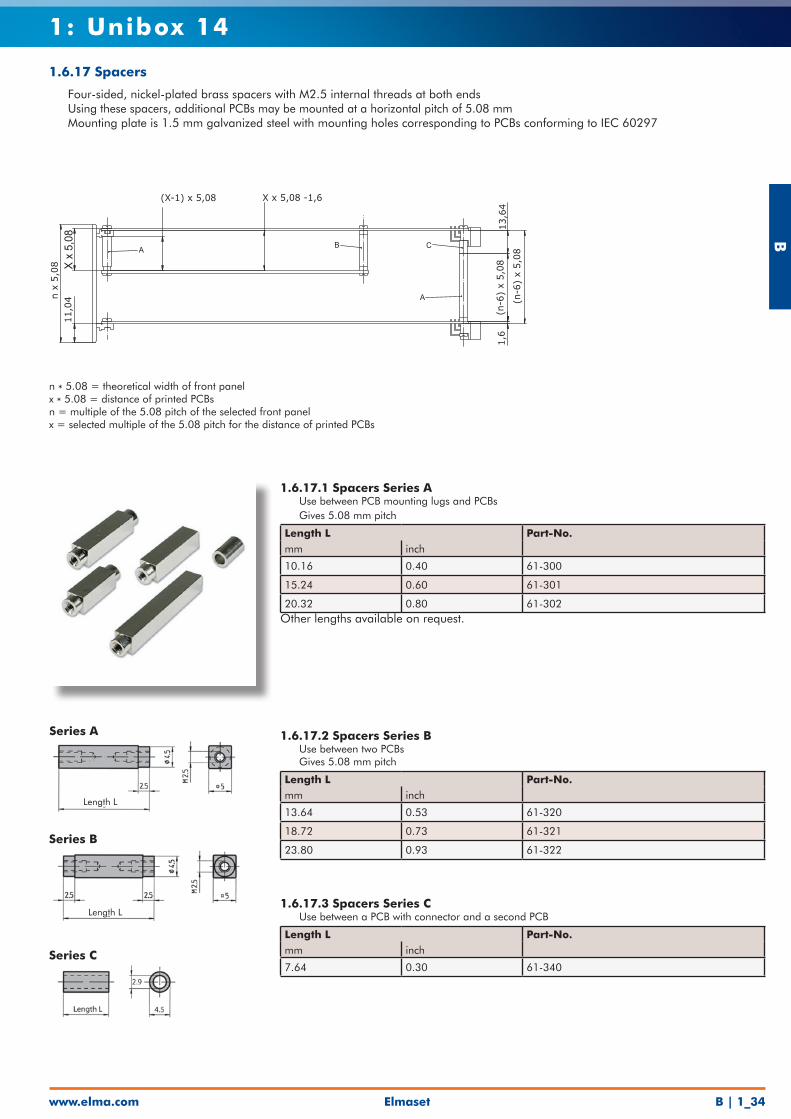
1.6.17.1 Spacers Series A• Use between PCB mounting lugs and PCBs• Gives 5.08 mm pitch
Length L Part-No. mm inch
10.16 0.40 61-300
15.24 0.60 61-301
20.32 0.80 61-302Other lengths available on request.
A B C
A (n-6
) x
5,0
8
1,6
(n-6
) x
5,0
813,6
4
X x 5,08 -1,6(X-1) x 5,08
X x
5,08
11,0
4n x
5,0
8
1.6.17.2 Spacers Series B• Use between two PCBs• Gives 5.08 mm pitch
Length L Part-No. mm inch
13.64 0.53 61-320
18.72 0.73 61-321
23.80 0.93 61-322
1.6.17.3 Spacers Series C• Use between a PCB with connector and a second PCB
Length L Part-No. mm inch
7.64 0.30 61-340
n * 5.08 = theoretical width of front panelx * 5.08 = distance of printed PCBsn = multiple of the 5.08 pitch of the selected front panelx = selected multiple of the 5.08 pitch for the distance of printed PCBs
Length L
Series A
Length L
Series B
Series C
1.6.17 Spacers
• Four-sided, nickel-plated brass spacers with M2.5 internal threads at both ends• Using these spacers, additional PCBs may be mounted at a horizontal pitch of 5.08 mm• Mounting plate is 1.5 mm galvanized steel with mounting holes corresponding to PCBs conforming to IEC 60297
B
www.elma.comElmasetB | 1_35
1: Unibox 14
5.5 6.5
Length L
5.5
M3
M3
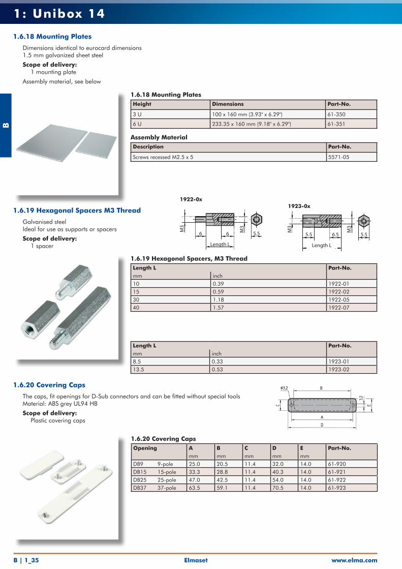
1.6.18 Mounting Plates
• Dimensions identical to eurocard dimensions• 1.5 mm galvanized sheet steel
• Scope of delivery: • 1 mounting plate
• Assembly material, see below
1.6.18 Mounting PlatesHeight Dimensions Part-No.
3 U 100 x 160 mm (3.93" x 6.29") 61-350
6 U 233.35 x 160 mm (9.18" x 6.29") 61-351
Assembly MaterialDescription Part-No.
Screws recessed M2.5 x 5 5571-05
1.6.19 Hexagonal Spacers M3 Thread
• Galvanised steel• Ideal for use as supports or spacers
• Scope of delivery: • 1 spacer
1.6.19 Hexagonal Spacers, M3 ThreadLength L Part-No.mm inch10 0.39 1922-0115 0.59 1922-0230 1.18 1922-0540 1.57 1922-07
Length L Part-No. mm inch8.5 0.33 1923-0113.5 0.53 1923-02
1.6.20 Covering Caps
• The caps, fit openings for D-Sub connectors and can be fitted without special tools• Material: ABS grey UL94 HB
• Scope of delivery: • Plastic covering caps
1.6.20 Covering CapsOpening A B C D E Part-No.
mm mm mm mm mmDB9 9-pole 25.0 20.5 11.4 32.0 14.0 61-920DB15 15-pole 33.3 28.8 11.4 40.3 14.0 61-921DB25 25-pole 47.0 42.5 11.4 54.0 14.0 61-922DB37 37-pole 63.5 59.1 11.4 70.5 14.0 61-923
1922-0x1923-0x
6 6
Length L
M3
M3
5.5
Elmaset
B
www.elma.com B | 1_36
1: Unibox 14
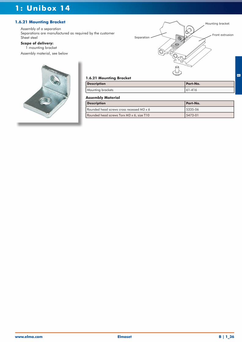
1.6.21 Mounting Bracket
• Assembly of a separation• Separations are manufactured as required by the customer• Sheet steel
• Scope of delivery: • 1 mounting bracket
• Assembly material, see below
1.6.21 Mounting BracketDescription Part-No.
Mounting brackets 61-416
Assembly MaterialDescription Part-No.
Rounded head screws cross recessed M3 x 6 5335-06
Rounded head screws Torx M3 x 6, size T10 5473-01
Mounting bracket
SeparationFront extrusion
B
www.elma.comElmasetB | 1_37
1: Unibox 14
106.4
3 0
M4
0 3 11 18
29.3 35.3
0 5
3.2/5.08
Card Guide Mounting side
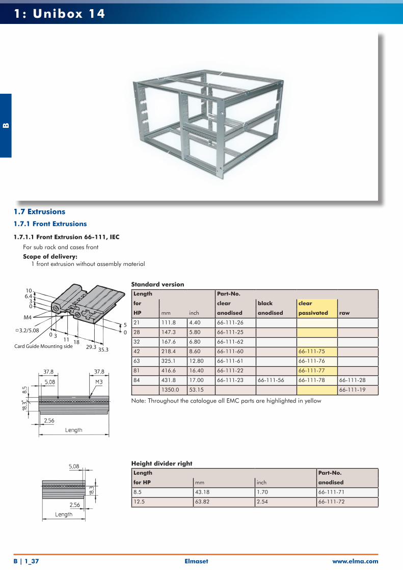
Standard versionLength Part-No.
for clear black clear
HP mm inch anodised anodised passivated raw
21 111.8 4.40 66-111-26
28 147.3 5.80 66-111-25
32 167.6 6.80 66-111-62
42 218.4 8.60 66-111-60 66-111-75
63 325.1 12.80 66-111-61 66-111-76
81 416.6 16.40 66-111-22 66-111-77
84 431.8 17.00 66-111-23 66-111-56 66-111-78 66-111-28
1350.0 53.15 66-111-19
Height divider rightLength Part-No.
for HP mm inch anodised
8.5 43.18 1.70 66-111-71
12.5 63.82 2.54 66-111-72
1.7 Extrusions
1.7.1 Front Extrusions
1.7.1.1 Front Extrusion 66-111, IEC
• For sub rack and cases front
• Scope of delivery: • 1 front extrusion without assembly material
Note: Throughout the catalogue all EMC parts are highlighted in yellow
Elmaset
B
www.elma.com B | 1_38
1: Unibox 14
38
60
10.50
�xing holefor handle
0
27.6
03
6
38
�xing holefor handle
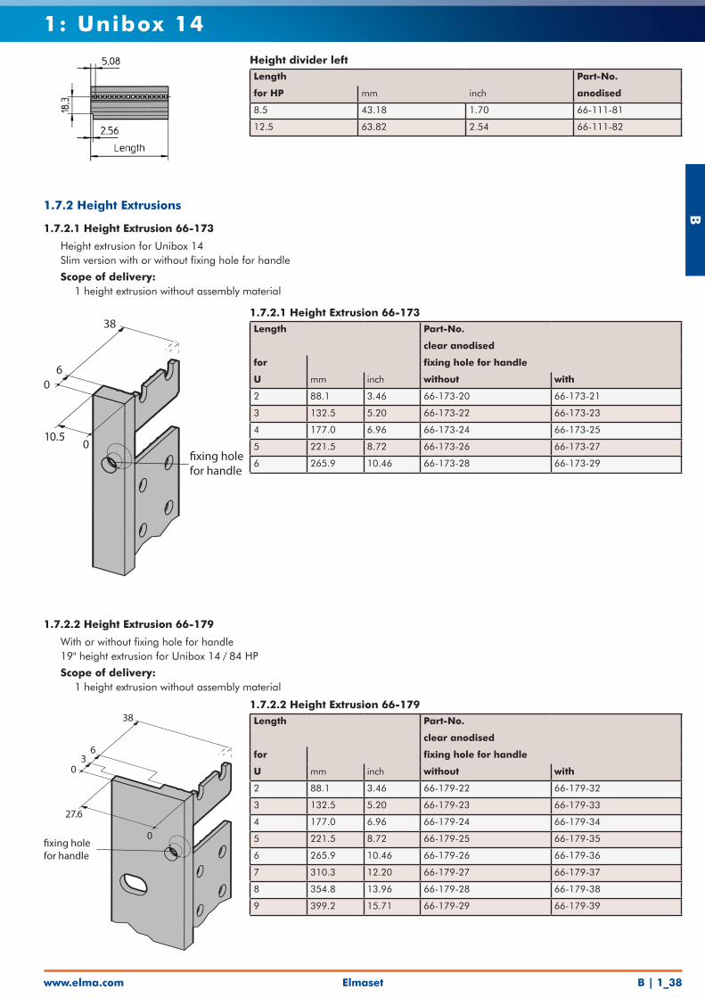
1.7.2.1 Height Extrusion 66-173Length Part-No.
clear anodised
for fixing hole for handle
U mm inch without with
2 88.1 3.46 66-173-20 66-173-21
3 132.5 5.20 66-173-22 66-173-23
4 177.0 6.96 66-173-24 66-173-25
5 221.5 8.72 66-173-26 66-173-27
6 265.9 10.46 66-173-28 66-173-29
1.7.2.2 Height Extrusion 66-179Length Part-No.
clear anodised
for fixing hole for handle
U mm inch without with
2 88.1 3.46 66-179-22 66-179-32
3 132.5 5.20 66-179-23 66-179-33
4 177.0 6.96 66-179-24 66-179-34
5 221.5 8.72 66-179-25 66-179-35
6 265.9 10.46 66-179-26 66-179-36
7 310.3 12.20 66-179-27 66-179-37
8 354.8 13.96 66-179-28 66-179-38
9 399.2 15.71 66-179-29 66-179-39
Height divider leftLength Part-No.
for HP mm inch anodised
8.5 43.18 1.70 66-111-81
12.5 63.82 2.54 66-111-82
1.7.2 Height Extrusions
1.7.2.1 Height Extrusion 66-173
• Height extrusion for Unibox 14• Slim version with or without fixing hole for handle
• Scope of delivery: • 1 height extrusion without assembly material
1.7.2.2 Height Extrusion 66-179
• With or without fixing hole for handle• 19" height extrusion for Unibox 14 / 84 HP
• Scope of delivery: • 1 height extrusion without assembly material
B
www.elma.comElmasetB | 1_39
1: Unibox 14
30
22
7
0
08.1
17.513.9
7.45
0
7.45
13.917.5
0 5.4
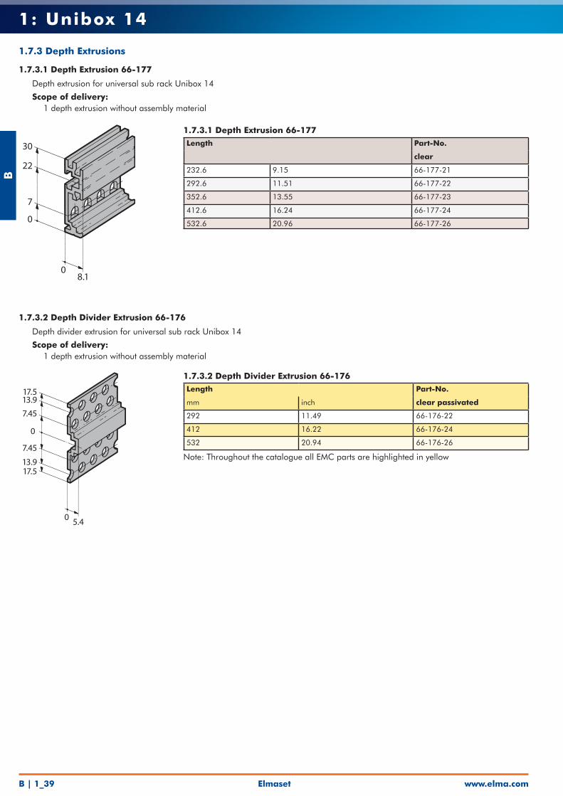
1.7.3.1 Depth Extrusion 66-177Length Part-No.
clear
232.6 9.15 66-177-21
292.6 11.51 66-177-22
352.6 13.55 66-177-23
412.6 16.24 66-177-24
532.6 20.96 66-177-26
1.7.3.2 Depth Divider Extrusion 66-176Length Part-No.
mm inch clear passivated
292 11.49 66-176-22
412 16.22 66-176-24
532 20.94 66-176-26
1.7.3 Depth Extrusions
1.7.3.1 Depth Extrusion 66-177
• Depth extrusion for universal sub rack Unibox 14
• Scope of delivery: • 1 depth extrusion without assembly material
1.7.3.2 Depth Divider Extrusion 66-176
• Depth divider extrusion for universal sub rack Unibox 14
• Scope of delivery: • 1 depth extrusion without assembly material
Note: Throughout the catalogue all EMC parts are highlighted in yellow
Elmaset
B
www.elma.com B | 1_40
1: Unibox 14
8.65.22.2
0M4
3.2/5.080 3 11
1829.3
4.30
Card Guide Mounting side
50
29.1181130
3.2/5.08
M4
8.756.4
30
Card Guide Mounting side
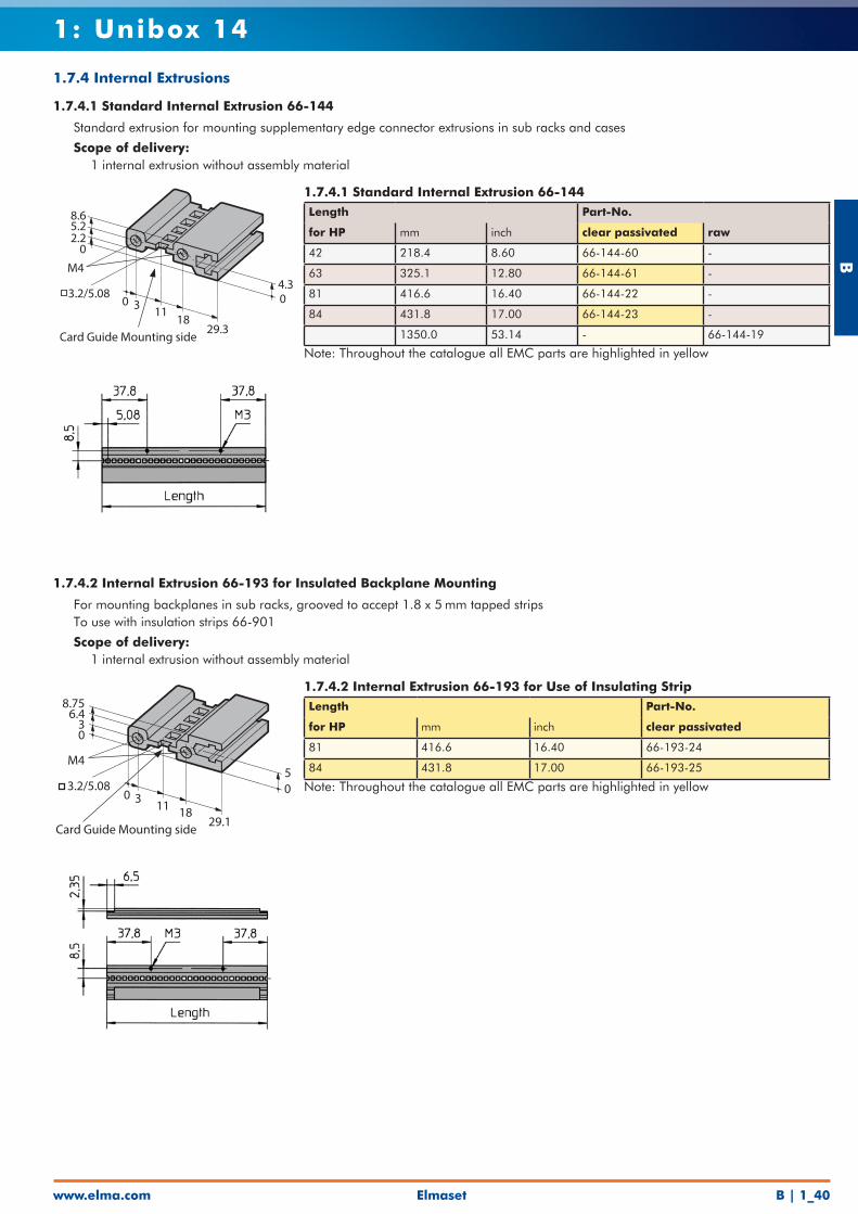
1.7.4.1 Standard Internal Extrusion 66-144Length Part-No.
for HP mm inch clear passivated raw
42 218.4 8.60 66-144-60 -
63 325.1 12.80 66-144-61 -
81 416.6 16.40 66-144-22 -
84 431.8 17.00 66-144-23 -
1350.0 53.14 - 66-144-19
1.7.4.2 Internal Extrusion 66-193 for Use of Insulating StripLength Part-No.
for HP mm inch clear passivated
81 416.6 16.40 66-193-24
84 431.8 17.00 66-193-25
1.7.4 Internal Extrusions
1.7.4.1 Standard Internal Extrusion 66-144
• Standard extrusion for mounting supplementary edge connector extrusions in sub racks and cases
• Scope of delivery: • 1 internal extrusion without assembly material
1.7.4.2 Internal Extrusion 66-193 for Insulated Backplane Mounting
• For mounting backplanes in sub racks, grooved to accept 1.8 x 5 mm tapped strips• To use with insulation strips 66-901
• Scope of delivery: • 1 internal extrusion without assembly material
Note: Throughout the catalogue all EMC parts are highlighted in yellow
Note: Throughout the catalogue all EMC parts are highlighted in yellow
B
www.elma.comElmasetB | 1_41
1: Unibox 14
4.352.4
02.4
4.35
Ø3.2/5.0801.8 3.2
Screw M2.5 x 12
Tapped strip
Backplane
Insulation strip
Internal extrusion
500 3 11
1832.2
3.2/5.08
M4
8.756.4
30
Card Guide Mounting side
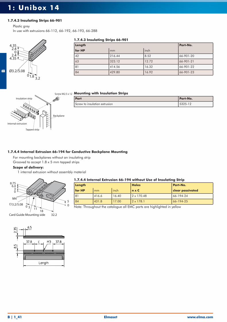
1.7.4.3 Insulating Strips 66-901Length Part-No.
for HP mm inch
42 216.44 8.52 66-901-20
63 323.12 12.72 66-901-21
81 414.56 16.32 66-901-22
84 429.80 16.92 66-901-23
Mounting with Insulation StripsPart Part-No.
Screw to insulation extrusion 5325-12
1.7.4.4 Internal Extrusion 66-194 without Use of Insulating StripLength Holes Part-No.
for HP mm inch n x C clear passivated
81 416.6 16.40 2 x 170.48 66-194-24
84 431.8 17.00 2 x 178.1 66-194-25
1.7.4.3 Insulating Strips 66-901
• Plastic grey• In use with extrusions 66-112, 66-192, 66-193, 66-288
1.7.4.4 Internal Extrusion 66-194 for Conductive Backplane Mounting
• For mounting backplanes without an insulating strip• Grooved to accept 1.8 x 5 mm tapped strips
• Scope of delivery: • 1 internal extrusion without assembly material
Note: Throughout the catalogue all EMC parts are highlighted in yellow
Elmaset
B
www.elma.com B | 1_42
1: Unibox 14
19.815.7
2.350
03.25.7
M2.5/5.08
Ø3.2/5.08
Ø3.2/5.08
22.218.6
2.40
0 3.2 6.1
M2.5/5.08
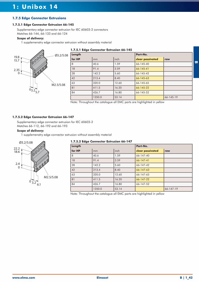
1.7.5.1 Edge Connector Extrusion 66-145Length Part-No.
for HP mm inch clear passivated raw
8 40.6 1.59 66-145-40
18 91.4 3.59 66-145-41
28 142.2 5.60 66-145-42
42 213.4 8.40 66-145-63
63 320.0 12.60 66-145-65
81 411.5 16.20 66-145-22
84 426.7 16.80 66-145-52
1350.0 53.14 66-145-19
1.7.5.2 Edge Connector Extrusion 66-147Length Part-No.
for HP mm inch clear passivated raw
8 40.6 1.59 66-147-40
18 91.4 3.59 66-147-41
28 142.2 5.60 66-147-42
42 213.4 8.40 66-147-63
63 320.0 12.60 66-147-65
81 411.5 16.20 66-147-22
84 426.7 16.80 66-147-52
1350.0 53.14 66-147-19
1.7.5 Edge Connector Extrusions
1.7.5.1 Edge Connector Extrusion 66-145
• Supplementary edge connector extrusion for IEC 60603-2 connectors• Matches 66-144, 66-133 and 66-124
• Scope of delivery: • 1 supplemenatry edge connector extrusion without assembly material
1.7.5.2 Edge Connector Extrusion 66-147
• Supplementary edge connector extrusion for IEC 60603-2• Matches 66-112, 66-192 and 66-193
• Scope of delivery: • 1 supplemenatry edge connector extrusion without assembly material
Note: Throughout the catalogue all EMC parts are highlighted in yellow
Note: Throughout the catalogue all EMC parts are highlighted in yellow


![[소셜캠페인] 유니클로_유니박스 사례(Social Campaign Uniqlo Unibox Campaign)](https://static.fdocuments.net/doc/165x107/5456cc12af79594e128b468c/-social-campaign-uniqlo-unibox-campaign.jpg)