Datalogging Option V2.0 for µ-blox GPS Receiver Modules µ...
37
μ-blox ag Zürcherstrasse 68 CH-8800 Thalwil Switzerland Phone +41 1 722 7444 Fax +41 1 722 7447 http://www.u-blox.com USER’SMANUAL Wereserveallrightsinthisdocumentandintheinformationcontainedtherein.Reproduction,useordisclosuretothirdpartieswithoutexpressauthorityisstrictlyforbidden. ©2001µ-bloxag. GPS.G1-X-00011 Page1 GPS Receiver with integrated Datalogger Datalogging Option V2.0 for μ-blox GPS Receiver Modules GPS.G1-X-00011,April3,2001 Formostcurrentdatasheets,pleasevisitwww.u-blox.com
Transcript of Datalogging Option V2.0 for µ-blox GPS Receiver Modules µ...

µ-blox ag
�
Zürcherstrasse 68 CH-8800 Thalwil Switzerland
Phone +41 1 722 7444 Fax +41 1 722 7447 http://www.u-blox.com
USER’S�MANUAL�
We�reserve�all�rights�in�this�document�and�in�the�information�contained�therein.�Reproduction,�use�or�disclosure�to�third�parties�without�express�authority�is�strictly�forbidden.� ©�2001�µ-blox�ag.�
GPS.G1-X-00011� � Page�1�
�
�
�
�
GPS Receiver with integrated Datalogger
Datalogging Option V2.0
for µ-blox GPS Receiver Modules� GPS.G1-X-00011,�April�3,�2001�
For�most�current�data�sheets,�please�visit�www.u-blox.com�

Datalogging�Option�User’s�Manual� � µ-blox�ag�
GPS.G1-X-00011� � Page�2�
CONTENTS
1 Features........................................................................................................................ 4
2 Introduction ................................................................................................................. 5
3 Installation Guide ........................................................................................................ 6
4 System Overview......................................................................................................... 7
5 Using the Logger ......................................................................................................... 9
5.1 Communication�with�the�Logger...................................................................................................... 9
5.2 Filter�Settings .................................................................................................................................. 9
5.2.1 GPIO�Filter.............................................................................................................................. 10
5.2.2 Position�Fix�Filter..................................................................................................................... 11
5.3 Default�settings�of�the�datalogger .................................................................................................. 13
5.4 Protocol�Extension ......................................................................................................................... 14
5.4.1 Input�Messages ...................................................................................................................... 14
5.4.2 Output�Messages ................................................................................................................... 17
5.4.3 Transferring�logged�data�using�the�extended�protocol .............................................................. 20
5.5 Storage�Format ............................................................................................................................. 21
5.5.1 Empty�Storage�Record............................................................................................................. 21
5.5.2 Position�Fix�Storage�Records .................................................................................................... 21
5.5.3 GPIO�Storage�Records............................................................................................................. 23
5.5.4 ESCAPE�Type�Storage�Records................................................................................................. 23
5.6 Decompressing�a�downloaded�memory�block ................................................................................. 23
6 Transferring logged data using u-logger.exe.......................................................... 25
6.1 Setup�the�communication .............................................................................................................. 25
6.2 Configure�the�GPS�logging�parameters........................................................................................... 26
6.3 General�logging�configuration........................................................................................................ 26
6.3.1 Position�fix�logging�configuration ............................................................................................ 26
6.3.2 GPIO�logging�configuration..................................................................................................... 28
6.4 Download�or�erase�the�logged�data................................................................................................ 30
6.5 Conversion�of�logged�data............................................................................................................. 31
6.6 Fix�Logging�Performance�Example .................................................................................................. 32
6.6.1 Real�Example.......................................................................................................................... 32
7 Related Documents.................................................................................................... 34
A Glossary ..................................................................................................................... 35

Datalogging�Option�User’s�Manual� � µ-blox�ag�
GPS.G1-X-00011� � Page�3�
B Contact ....................................................................................................................... 36
Revision History............................................................................................................... 37
�

Datalogging�Option�User’s�Manual� � µ-blox�ag�
GPS.G1-X-00011� � Page�4�
1 FEATURES
��SW�Enhancement�for�the�µ-blox�GPS-MS1E�and�GPS-PS1E�
- Integrated�Datalogger�
- Fully�compatible�to�standard�receivers�
- Configuration�through�the�serial�interface�
- no�additional�external�circuitry�required�
�
��Data�compression�
- GPS-MS1E-DL�stores�up�to�100’000�positions�
- GPS-PS1E-DL�stores�up�to�20’000�positions�
�
��Intelligent�Logging�algorithm�triggered�by�GPS�events.�
�
��Various�configurable�filter�parameters�
- Time�
- Distance�
- Velocity�
�
��General�purpose�Input�/�Output�(GPIO)�Logging.�
- 12�independent�pins�
- Pins�are�configurable�as�Inputs�or�Outputs�
- The�logger�observes�Inputs�and�Outputs�
- Outputs�may�be�configured�high�or�low�
�
��External�requirements:�
- Power�supply�for�GPS�
- Backup�battery�for�real�time�clock�and�SRAM�
- Serial�interface�for�NMEA�or�SiRF�binary�data�
- Passive�or�active�Antenna�
�

Datalogging�Option�User’s�Manual� � µ-blox�ag�
GPS.G1-X-00011� � Page�5�
2 INTRODUCTION
µ-blox�offers�Software�Enhancements�to�standard�GPS�receivers.�An�integrated�datalogger�enables�the�receiver�to�store�position,�time�and�events�in�the�onboard�flash�memory.�A�datalogging�enabled�GPS�receiver�fulfils�the�specification� of� a� standard� receiver.� For� a� description� of� the� hardware� please� refer� to� the� datasheet� of� the�respective� receiver.� This� document� is� intended� to� explain� the� concept� of� the� logging� implementation,� the�protocol�to�configure�the�receiver�and�a�real�world�example.��
The�datalogger�opens�up�a�wide�range�of�applications.�
- Vehicle�tracking��
- Road�pricing�systems��
- Automatic�project�accounting�for�field�personnel��
- Behavioural�studies�of�animals��
- Time�table�analysis�for�public�transport�systems�
- …�
µ-blox�offers�a�PC�utility,�that�enables�you�to�easily�configure�the�datalogger�and�read�out�stored�data.�This�PC�utility�named�‘u-Logger.exe’�is�described�in�a�separate�chapter.�
The�Datalogging�FW�is�available�for�the�GPS-MS1E�as�well�as�for�the�GPS-PS1E.� In�order�to�get�a�Datalogging�enabled�GPS�receiver�the�modules�has�to�be�ordered�in�the�Datalogging�version.�The�ordering�numbers�are�GPS-MS1E-DL�and�GPS-PS1E-DL�for�the�GPS-MS1E�and�GPS-PS1E�with� integrated�datalogger,�resp.� It� is�possible�to�up-grade�a�Datalogging�enabled�receiver�to�the�latest�version�of�the�datalogger�using�the�update�utility�available�on�our�homepage�(http://www.u-blox.com).�See�the�Update Manual�for�details�on�the�up-date�procedure.�
Due�to�the�different�HW�setups�of�the�two�GPS�receivers,�there�are�some�differences�in�the�specification�of�the�datalogger:�
Feature GPS-MS1E-DL GPS-PS1E-DL FLASH�Memory�available� 5�Mbit� 1�Mbit�Max.Number�of�Logs� 100’000� 20’000�GPIO� Yes,�12�Pins� no�
Table 1: HW specifics

Datalogging�Option�User’s�Manual� � µ-blox�ag�
GPS.G1-X-00011� � Page�6�
3 INSTALLATION GUIDE
The�Logging�Option�is�a�special�firmware.�Firmware�‘134l283.s3’�contains�the�data�logger.�This�firmware�can�be�used� on� GPS-MS1–DL,� GPS-MS1E–DL,� GPS-PS1–DL� or� GPS-PS1E–DL� modules� only.� It� will� not� work� in�combination�with� any� other�module.� The� firmware�may� be� updated�with� the� standard� ‘gpsxs-dl.exe’� update�utility.��
The� additional� program� ‘u-logger.exe’� is� a� standalone� application� for� the� PC.� It� requires�Windows� 95/98� or�Microsoft�Windows�NT�4.�
�

Datalogging�Option�User’s�Manual� � µ-blox�ag�
GPS.G1-X-00011� � Page�7�
4 SYSTEM OVERVIEW
The�Software�is�optimized�for�maximum�stored�data�and�maximum�flexibility.�A�differential�storage�technology�is�used� to� store� data� in� the� flash� memory.� There� are� two� main� logging� functionalities:� position� fix� and� GPIO�logging.� Both� can� be� configured� separately� and� are� totally� independent� from�each� other.� In� addition� to� the�traditional� position� fix� logging,� it� can� also� be� configured� to� store� changes� on� the�GPIO� Pins.� For� example,� a�temperature�sensor�or�an�event,�e.g.�ignition�on/off,�could�be�logged.�The�information�stored�includes:��
- GPS�Timestamp�(WNO,�TOW),�not�UTC�corrected,�resolution�1�[s]��
- Position�(ECEF),�resolution�1�[m]��
- Velocity,�range�0…1023�[km/h],�resolution�1�[km/h]��
- Number�of�satellites�used�for�navigation��
- DGPS�used��
- GPIO�signal�levels,�GPIO�pins�0�to�11�
Figure� 1� describes� the� software� structure� of� the� datalogger.� There� are� the� two�main� logging� functionalities:�position�fix�and�GPIO�logging.�
In� case� of� position� fix� logging� the�GPS� receivers� stores� data� in� the� onboard� flash�memory� in� addition� to� the�transmission�over�the�serial�port.�Basically�every�position�fix�may�be�stored�in�the�FLASH.�But�in�most�applications�filters�are�used.�These�prevent�the�datalogger�from�storing�all�the�positions�into�the�Flash�memory�and�lengthen�total�logging�time.�
Chapter�5.2�describes�these�filters.�The�user�may�configure�the�filter�parameters�to�suit�his�application.�
In�case�of�GPIO� logging�the�GPS�receiver�stores�data�on�the�basis�of�an�event�which�recurs�every�second.� � In�addition�to�logging�it�is�possible�to�control�the�GPIO’s.�A�GPIO�may�be�used�as�input�or�output.�It�is�also�possible�to� set� the� output� level� to� High� (VCC)� or� Low� (Gnd).� Controlling� the� GPIOs� is� independent� on� the� logging�functionality.�

Datalogging�Option�User’s�Manual� � µ-blox�ag�
GPS.G1-X-00011� � Page�8�
Datalogger
enable?
Yes
No
Flash
full ?
Position Fix
Filter
Store data on
Flash memory
END
Datalogger
enable?
Yes
No
Flash
full ?
GPIO
Filter
Yes Yes
No No
event trigger
every second
Position
valid?
Yes
No
New Navigation Solution
�
Figure 1: Functionality of Datalogger
�

Datalogging�Option�User’s�Manual� � µ-blox�ag�
GPS.G1-X-00011� � Page�9�
5 USING THE LOGGER
5.1 Communication with the Logger
The�controlling�of�the�Logger�takes�place�using�SiRF�binary�Protocol�via�serial�port�(UART).�Additional�SiRF�binary�commands�(proprietary)�allow�to�adjust�logger�options�and�to�download�stored�data.�
Request
Message
Response
Message
Evaluation
of Message
Build Response
Message
ProcessingUART
Figure 2: Model of Data Stream
Figure� 2� shows� the� communication� process� with� the� data� logger.� The� process� is� initiated� by� an� incoming�message.�The�content�of�the�message� is�evaluated�and�processed.�After�processing�a�response� is�created�and�transmitted�via�UART.�
The� Logging� Option� defines� a� new� set� of� SiRF� binary� protocol� messages.� The� messages� can� be� used� for�configuring�the�filter�parameters.�This�enables�user-defined�position,�time�and�velocity� logging� in�the�onboard�memory.�Download�and�erasing�of�the�flash�is�also�supported�by�this�protocol�extension.�Although�the�logging�option� is� designed� as� an� extension� to� the� SiRF� binary� protocol,� data� is� also� stored� while� in� NMEA� mode.�However,�to�configure�the�logger�and�download�data,�SiRF�binary�protocol�is�needed.�
5.2 Filter Settings
In�addition�to�the�data�compression�performed�during�the�storage�of�a�data�record,�the�datalogger�offers�the�possibility�to�further�reduce�the�number�of�stored�data�records�by�configuring�special�filters.�These�filters�prevent�the� logger�from�storing�unnecessary�data,�e.g.� if�a�vehicle� is�not�moving.�However�these�filters�have�to�be�set�according�to�the�requirement�of�the�final�application.�The�configuration�is�done�using�the�additional�SiRF�binary�commands.�
Basically� one� can� distinguish� two�different� types� of� filters:�Minimum� filters� prevent� a� data� record� from�being�stored,�maximum�filters�in�contrary�bypass�the�minimum�filters,�if�exceed.�Therefore�maximum�filters�can�be�used�to�make�sure�that�data�is�stored,�e.g.�after�maximum�10h.�
This� chapter� describes� the� possible� filter� settings.� An� easy�way� to� set� these� filters� is� by� connecting� the� GPS�receivers� to� a� PC� and� to� use� the� ‘u-Logger.exe’� for� the� configuration.� In� an� embedded� environment� the�configuration�could�be�set�by�a�controller,�which�sends�the�according�SiRF�binary�message�to�the�GPS�receiver.�

Datalogging�Option�User’s�Manual� � µ-blox�ag�
GPS.G1-X-00011� � Page�10�
5.2.1 GPIO Filter
The�GPIO�logger�is�invoked�every�second.�During�storage,�all�Pin�states�will�be�saved.�See�chapter�5.5.3�for�the�definition�of�the�storage�format.��
The�GPIO�logging�algorithm�stores�the�following�information:�
- Timestamp�of�stored�position,�Resolution�1�[s].��
- Values�of�all�GPIO�pins�0�to�11.��
The�filter�sets�a�time�and�event�mask�which�control�the�storage.�
�
GPIO
enable?
>Min
Time?
Yes
Yes
No
event trigger every second
>Max
Time?
Store all
Pin Conditions
END
Yes
Yes
No
No
No
GPIO Filter
..........
Pin 0
enable?
Pin 0
change?
Yes
No
Pin 11
enable?
Pin 11
change?
No NoEnd
End
GPIO Pin's
0 1 2 11
Yes Yes
�
Figure 3: GPIO filter

Datalogging�Option�User’s�Manual� � µ-blox�ag�
GPS.G1-X-00011� � Page�11�
5.2.1.1 GPIO Filter Algorithm in Pseudocode
The�algorithm�stores�according�to�the�following�pseudo�code,�which�is�called�once�every�second:��
-- Calculate the difference between now and the last storage time.
T_Diff = Current.Time - Last.GPIOTime
-- Only store if the filter checks are ok.
-- The lower bounds are anded the higher bounds are ored. IF ((((Current.GPIOValue & Mask) <> (Last.GPIOValue & Mask)) AND
(T_Diff > T_Min)) OR (T_Diff > T_Max)) THEN
IF (T_Diff > 65535) THEN
--Store a GPIO_FULL record to the flash. ELSE
--Store a GPIO_INC record to the flash. END IF
--Backup the storage time and GPIO values.
Last.GPIOTime = Current.Time
Last.GPIOValue = Current.GPIOValue
END IF
5.2.2 Position Fix Filter This�filter�is�active�only�if�a�new�and�valid�position�fix�has�been�calculated.��
The�position�fix�logging�algorithm�stores�the�following�information:��
- Timestamp�of�stored�position,�Resolution�1�[s].��
- Velocity.�Range�0�...1023�[km=h]�,�Resolution�1�[km=h].��
- Position.�Full�ECEF�Position.�Resolution�1�[m].��
- Number�of�SVs�(<3,�3,�4�or�>4�SVs).��
- DGPS�used.�

Datalogging�Option�User’s�Manual� � µ-blox�ag�
GPS.G1-X-00011� � Page�12�
Fix Position
enable?
4 SV solution
request ?
4 SV
solution?
Yes
Yes
Yes
Store data on
Flash memory
END
No
No No
Position Fix Filter
No
>Min
Time?
>Min
Distance?
>Min
Speed?
>Max
Time?
>Max
Distance?>Max
Speed?Yes
Yes
Yes
No
No
End
Yes Yes Yes
End End
New and valid Navigation Solution
No No No
�
Figure 4: Position fix filter
5.2.2.1 Position Fix filter Algorithm in pseudo code
The�algorithm�stores�according�to�the�following�pseudo�code,�which�is�called�whenever�a�position�fix�is�done:��
--Calculate the difference between now and the last storage time.
T_Diff = Current.Time - Last.FixTime
--Calculate the difference between here and the last stored position. D_Diff = ABS(Current.Position - Last.Position)
--Get the current speed.
V = Current.Speed

Datalogging�Option�User’s�Manual� � µ-blox�ag�
GPS.G1-X-00011� � Page�13�
--Only store if the filter checks are ok.
--The lower bounds are anded the higher bounds are ored. IF (((T_Diff > T_Min) AND (D_Diff > D_Min) AND (V > V_Min)) OR
(T_Diff > T_Max) OR (D_Diff > D_Max) OR (V > V_Max)) THEN
IF ((D_Diff > 32767) OR (T_Diff > 65535)) THEN
--Store a FIX_FULL record to the flash. ELSE IF (D_Diff > 511) THEN
--Store a FIX_INCL record to the flash. ELSE IF (D_Diff > 15) THEN
--Store a FIX_INCM record to the flash. ELSE
--Store a FIX_INCS record to the flash. END IF
--Backup storage time and position.
Last.FixTime = Current.Time
Last.Position = Current.Position
END IF
5.3 Default settings of the datalogger
The�logging�firmware�has�the�following�default�settings:�
Validity Parameter Value Protocol Logger� Flags� Enabled� MID�0xBC�
Flags� Enabled�Min�Time� 5�s�Max�Time� 3600�s�Min�Distance� 150�m�Max�Distance� 0�m�(Disabled)�Min�Speed� 0�m/s�(Disabled)�
Position�Fix�Filter�
Max�Speed� 0�m/s�(Disabled)�
MID�0xBE�
Flags� Disabled�Min�Time� 5�s�Max�Time� 0�s�(Disabled)�Mask�(Configuration�mask)� 0x000�(None)�
GPIO�Filter�
Check�(Logging�mask)� 0x000�(Not�Set)�GPIO�Settings� Input�/�Output�mask� 0x000�(Not�Set)�GPIO�Settings� Value�mask� 0x000�(Not�Set)�
MID�0xCA�
Table 2: Datalogger Default settings
Table�2�describes�the�default�settings�of�the�Logger.�The�column�‘Protocol’�refers�to�these�messages,�which�can�change� the� settings.� These� messages� are� used� to� control� the� datalogger,� e.g.� switch� it� on/off,� change� the�settings.��
The�logger�starts�automatically�during�the�first�system�start.�Only�the�Filters�with�above�described�settings�will�be�active.�

Datalogging�Option�User’s�Manual� � µ-blox�ag�
GPS.G1-X-00011� � Page�14�
5.4 Protocol Extension
The�logging�protocol�extension�can�be�used�with�SiRF�Binary�protocol�only.�Please�refer�to�the�µ-blox�protocol�documentation�for�a�specification�of�the�transport�and�verification� layer.�This�document�describes�the�payload�portion�of�the�extended�SiRF�binary�protocol,�only.�The�following�Input
1
�and�Output�messages�are�supported:�
5.4.1 Input Messages
MID Message Description 0xB6� LogSectorErase�(responses�with�LogSectorEraseEnd)� Erases�all�sectors�or�a�specified�sector�in�the�
Flash�memory�0xB8� LogRead�(responses�with�LogData)� Initiates�data�download�from�a�specified�
address�0xBA� LogPollSectorInfo�(responses�with�LogSectorInfo)� Requests�flash�sector�information�0xBB� LogPollInfo�(responses�with�LogInfo)� Requests�information�about�flash�memory�and�
logging�space�0xBC� LogSetConfig� Sets�general�logging�configuration�0xBD� LogPollConfig�(responses�with�LogConfig)� Requests�general�logging�configuration�0xBE� LogFixSetConfig� Sets�the�position�fix�logging�configuration�0xBF� LogFixPollConfig�(responses�with�LogFixConfig)� Requests�the�position�fix�logging�configuration�0xC0� LogGPIOSetConfig� Sets�the�GPIO�logging�configuration�0xC1� LogGPIOPollConfig�(responses�with�LogGPIOConfig)� Requests�the�GPIO�logging�configuration�
Table 3: Input Messages
5.4.1.1 LogSectorErase
This�message�causes�the�receiver�to�erase�a�specific�flash�sector.�The�receiver�disables�flash�writing.�After�erasing�the� receiver� returns� a� message� of� type� LogSectorEraseEnd� (0x7B).� After� erasing� sectors� you� must� reset� the�receiver.�Send� the�Navigation� Initialization�Message� (MID�=�0x80).�There�are� two�special� sector�numbers� that�erase�all�sectors�in�a�row.�If�you�send�the�message�with�0xFF�as�Sector�Number,�the�module�will�erase�all�used�sectors,�then�it�replies�with�the�LogSectorEraseEnd�Message�and�performs�a�reset.�If�you�send�the�message�with�0xFE� as� Sector� Number,� the� module� will� erase� all� sectors� regardless� of� the� usage,� then� it� replies� with� the�LogSectorEraseEnd�Message� and� performs� a� reset.� Keep� in�mind� that� the� erase� command�may� take� several�seconds�to�complete.�During�this�time�no�communication�is�possible.��
Field Type Description MID� U8� 0xB6
Sector� U8� Sector�Number�� � Payload:�2�Byte�
Table 4: LogSectorErase Message
5.4.1.2 LogRead
This�message� requests�512�bytes�of� stored�and�compressed� log� data.�The�module� returns�a�message�of� type�LogData�(0x79)��
Field Type Description MID� U8� 0xB8
Address� U32� Address�from�which�data�should�be�returned�� � Payload:�5�Byte�
Table 5: LogRead Message
���������������������������������������������������
1
�Input�as�seen�from�the�receiver,�i.e.�from�the�Host�PC�to�the�µ-blox�receiver.�

Datalogging�Option�User’s�Manual� � µ-blox�ag�
GPS.G1-X-00011� � Page�15�
5.4.1.3 LogPollSectorInfo
This�message�requests�information�on�a�specific�sector�of�the�flash�memory.�The�receiver�returns�a�message�of�type�LogSectorInfo�(0x7A).�
Field Type Description MID� U8� 0xBA
Sector� U8� Sector�number�� � Payload:�2�Byte�
Table 6: LogPollSectorInfo Message
5.4.1.4 LogPollInfo
This�message�requests�information�on�flash�memory�and�logging�space.�The�receiver�returns�a�message�of�type�LogInfo�(0x7C).�
Field Type Description MID� U8� 0xBB
� � Payload:�1�Byte�
Table 7: LogPollInfo Message
5.4.1.5 LogSetConfig
This�message�sets�the�general�logging�configuration.�
Field Type Description MID� U8� 0xBC
Flags� U16� Logging�Flags.�See�Table�9�for�meaning � � Payload:�3�Bytes�
Table 8: LogSetConfig Message
Bit # Meaning Parameters Bit�0� Logging�Control�� 0=Disabled�
1=Enabled�Bit�1� Logging�Debug�Messages�� 0=Disabled�
1=Enabled�Bit�2� Logging�Diagnostics�Strings�� 0=Disabled�
1=Enabled��Bit�7� Flash�1PPS�LED�when�logging�� 0=Disabled�
1=Enabled�
Table 9: LogSetConfig.Flags Bitmap
5.4.1.6 LogPollConfig
This�message� requests� the� general� logging� configuration.� The� receiver� returns� a�message� of� type� LogConfig�(0x7D).��
Field Type Description MID� U8� 0xBD
� � Payload:�1�Byte�
Table 10: LogPollConfig Message
5.4.1.7 LogFixSetConfig
This�message� sets� the�position� fix� logging�configuration.�The� lower�bounds� (min)�of� the� filter�parameters�are�AND-ed,�the�higher�bounds�are�OR-ed.�

Datalogging�Option�User’s�Manual� � µ-blox�ag�
GPS.G1-X-00011� � Page�16�
Field Type Description MID� U8� 0xBE
Flags� U16� Fix Logging Flags.�See�Table�12�for�meaning
T_min�[s]� U16�Time difference filter.�This�Field�sets�the�minimum�time�difference�with�which�a�record�maybe�stored.�0=disabled
T_max�[s]� U16�Time difference filter.�This�Field�sets�the�maximum�time�difference�with�which�a�record�is�stored�regardless�from�the�other�parameters.�0=disabled�
D_min�[m]� U16�Distance filter.�This�Field�sets�the�minimum�distance�with�which�a�record�may�be�stored.�0=disabled
D_max�[m]� U16�Distance filter.�This�Field�sets�the�maximum�distance�with�which�a�record�is�stored�regardless�from�the�other�parameters.�0=disabled�
V_min�[m/s]�
U16�Velocity filter.�This�Field�sets�the�minimum�speed�with�which�a�record�may�be�stored.�0=disabled
V_max�[m/s]�
U16�Velocity filter.�This�Field�sets�the�maximum�speed�with�which�a�record�is�stored�regardless�from�the�other�parameters.�0=disabled�
� � Payload:�15�Byte�
Table 11: LogFixSetConfig Message
Bit # Meaning Parameters Bit�0� Position�Fix�Logging�Control�� 0=Disabled�
1=Enabled�Bit�2� Output�Measured�Navigation�on�Serial�Port�(SiRF�Binary�
Message�2)�while�Logging�0=Output�1=Don't�Output�
Bit�3� Log�Filter�for�4SV�Solution��
1=Log�only�if�4�or�more�SV�used�0=Log�if�valid�navigation�solution�
Bit�6� Speed�Format�� 0=3D�Speed�1=2D�Speed,�Speed�over�ground�
Bit�7� Store�FULL�records�only� 0=Compressed�1=Uncompressed�
Table 12: LogFixSetConfig.Flags Bitmap
5.4.1.8 LogFixPollConfig
This� message� requests� the� position� fix� logging� configuration.� The� receiver� returns� a� message� of� type�LogFixConfig�(0x7E).�
Field Type Description MID� U8� 0xBF
� � Payload:�1�Byte�
Table 13: LogFixPollConfig Message
5.4.1.9 LogGPIOSetConfig
This�message�sets�the�GPIO�logging�configuration.�The�lower�bound�(min)�of�the�time�filter�is�AND-ed�with�the�gpio�filter,�the�higher�bound�is�OR-ed.�

Datalogging�Option�User’s�Manual� � µ-blox�ag�
GPS.G1-X-00011� � Page�17�
Field Type Description MID� U8� 0xC0
Flags� U16� GPIO Logging Flags.�See�Table�15�for�meaning�
T_min�[s]� U16�
Time difference filter.�This�Field�sets�the�minimum�time�difference�with�which�a�record�maybe�stored.�0=disabled
T_max�[s]� U16�
Time difference filter.�This�Field�sets�the�maximum�time�difference�with�which�a�record�is�stored�regardless�from�the�gpio�filter�parameters.�0=disabled�
Mask� U162
�Pin Mask,�Any�modification�applies�to�the�here�masked�pins�only.�(1�=�Change,�0�=�Leave)�
Direction� U162
�Direction Bitmask (1=Input,�0=Output)�
Value� U162
�Value Bitmask (1�=�High,�0�=�Low)�
Check� U162
�Check Bitmask (1=Log�if�Pin�changes)�
� � Payload:�15�Bytes�
Table 14: LogGPIOSetConfig Message
Bit # Meaning Parameters Bit�0� GPIO�Logging�Control�� 0=Disabled�
1=Enabled�Bit�7� Store�FULL�records�only,� 0=Compressed�
1=Uncompressed�
Table 15: LogGPIOSetConfig.Flags Bitmap
5.4.1.10 LogGPIOPollConfig
This�message�requests�the�GPIO�logging�configuration.�The�receiver�returns�a�message�of�type�LogGPIOConfig�(0x7F).�
�
Field Type Description MID� U8� 0xC1
� � Payload:�1�Byte�
Table 16: LogGPIOPollConfig Message
5.4.2 Output Messages
MID Message Description 0x79� LogData�(response�to�LogRead)� Logged�data�0x7A� LogSectorInfo�(response�to�LogPollSectorInfo)� Sector�information�0x7B� LogSectorEraseEnd�(response�to�LogSectorErase)� Indicates�the�end�of�a�sector�erase�0x7C� LogInfo�(response�to�LogPollInfo)� Contains�information�about�flash�architecture�
and�logging�space�0x7D� LogConfig�(response�to�LogPollConfig)� Contains�the�general�logging�configuration�0x7E� LogFixConfig�(response�to�LogFixPollConfig)� Contains�the�position�fix�logging�configuration�0x7F� LogGPIOConfig�(response�to�LogGPIOPollConfig)� Contains�the�GPIO�logging�configuration�
Table 17: Output messages
���������������������������������������������������
2
�Bitmask:�the�bit�X�represents�GPIO�X,�bits�12�to�15�are�not�used�

Datalogging�Option�User’s�Manual� � µ-blox�ag�
GPS.G1-X-00011� � Page�18�
5.4.2.1 LogData
This�message�is�sent�as�a�response�to�a�LogRead�message.�
Field Type Description MID� U8� 0x79
Start� U32� Start�address�of�this�512�Byte�Block.
Data[256]�256�x�U16�
Compressed�Data�See�chapter�‘Storage�Format’�for�a�description�of�the�compressed�data�structures�
� � Payload:�517�Bytes�
Table 18: LogData Message
5.4.2.2 LogSectorInfo
This�message�is�sent�as�a�response�to�a�LogPollSectorInfo�message.�
Field Type Description MID� U8� 0x7A
Sector� U8� sector�number Flags� U16� (reserved)�Size� U32� Size�of�this�sector�in�bytes.�
Base� U32�Start�address�of�this�sector.�To�be�used�with�LogRead.�
Free� U32� Number�of�bytes�available�in�this�sector.�� � Payload:�16�Bytes�
Table 19: LogSectorInfo Message
5.4.2.3 LogSectorEraseEnd
This�message�is�sent�as�a�response�to�a�LogSectorErase�message.�
Field Type Description MID� U8� 0x7B
Sector� U8� Sector�number � � Payload:�2�Bytes�
Table 20: LogSectorEraseEnd Message

Datalogging�Option�User’s�Manual� � µ-blox�ag�
GPS.G1-X-00011� � Page�19�
5.4.2.4 LogInfo
This�message�is�sent�as�a�response�to�a�LogPollInfo�message.�
Field Type Description MID� U8� 0x7C
S_First� U8�Index�of�first�sector�of�the�available�logging�space�(zerobased)
S_Last� U8�Index�of�last�sector�of�the�available�logging�space�(zerobased)
A_First� U32� First�address�in�the�logging�space. A_Last� U32� Last�address�in�the�logging�space. A_Start� U32� Start�address�of�the�used�logging�space. Size� U32� Size�of�the�used�logging�space.�� � Payload:�19�Bytes�
Table 21: LogInfo Message
5.4.2.5 LogConfig
This�message�is�sent�as�a�response�to�a�LogPollConfig�message.�
Field Type Description MID� U8� 0x7D
Flags� U16� See�LogSetConfig�message. � � Payload:�3�Bytes�
Table 22: LogConfig Message
5.4.2.6 LogFixConfig
This�message�is�sent�as�a�response�to�a�LogFixPollConfig�message.�
Field Type Description MID� U8� 0x7E
Flags� U16� See�LogFixSetConfig�message. T_min�[s]� U16� See�LogFixSetConfig�message.�T_max�[s]� U16� See�LogFixSetConfig�message.�D_min�[m]� U16� See�LogFixSetConfig�message.�D_max�[m]� U16� See�LogFixSetConfig�message.�V_min�[m/s]� U16� See�LogFixSetConfig�message.�V_max�[m/s]� U16� See�LogFixSetConfig�message.�� � Payload:�15�Bytes�
Table 23: LogFixConfig Message
5.4.2.7 LogGPIOConfig
This�message�is�sent�as�a�response�to�a�LogGPIOPollConfig�message.�
Field Type Description MID� U8� 0x7F
Flags� U16� See�LogGPIOSetConfig�message. T_min�[s]� U16� See�LogGPIOSetConfig�message.�T_max�[s]� U16� See�LogGPIOSetConfig�message.�Mask� U16� See�LogGPIOSetConfig�message.�Direction� U16� See�LogGPIOSetConfig�message.�Value� U16� See�LogGPIOSetConfig�message.�Check� U16� See�LogGPIOSetConfig�message.�� � Payload:�15�Bytes�
Table 24: LogGPIOConfig Message

Datalogging�Option�User’s�Manual� � µ-blox�ag�
GPS.G1-X-00011� � Page�20�
5.4.3 Transferring logged data using the extended protocol -- get information on the flash structure. -- send the message LogPollInfo and receive the message LogInfo.
-- allocate the required memory to store the data.
Data = MEMALLOC(Size)
-- now download all the data.
Address = A_Start
WHILE (Address < A_Start + Size)
-- now download the block from address Address.
-- send the message LogRead and receive the message LogData.
-- copy the received block to its position in Data.
-- calculate the starting address of the next block to download.
Address = Address + 512
END WHILE
-- decompress Data.
-- use the algorithm given in charter ‘Decompressing a downloaded memory block’.

Datalogging�Option�User’s�Manual� � µ-blox�ag�
GPS.G1-X-00011� � Page�21�
5.5 Storage Format
The�logged�data�is�stored�in�the�flash�memory�in�different�storage�records.�The�logging�algorithms�automatically�choose� the� type�of� the� storage� record.�The�data�compression�may�be� switched�off�by� setting� the� ‘store�FULL�records�only’�flag.�Separate�chapters�describe�the�logging�algorithms�and�the�decompressing.�
The�three�most�significant�bits�(bits�15�to�13)�determine�the�type�of�the�storage�record.�In�addition�to�the�basic�types,� a� flexible� storage� record,� the� so-called� escape� type� storage� record,� is� defined� for� future� logging�applications.�
3 Bits[15:13] Type Size [WORDS]
Description
111� NONE� 1� No�or�unwritten�data�100� FIX_FULL� 9� Position�Fix�data,�Full�storage�format�010� FIX_INCL� 5� Position�fix�data,�Large�incremental�Storage�format�000� FIX_INCM� 4� Position�fix�data,�Medium�incremental�Storage�format�110� FIX_INCS� 3� Position�fix�data,�small�incremental�storage�format�101� GPIO_FULL� 3� GPIO�data,�Full�storage�format�011� GPIO_INC� 2� GPIO�data,Incremental�storage�format�001� ESCAPE� var� Used�for�Future�logging�
Applications�
Table 25: Storage Types
5.5.1 Empty Storage Record
If� the� first� three�bits�are�all� '1',� then� the�word� is� considered�as�unwritten�data�and� is� skipped� therefore.�The�following�table�lists�the�layout�of�an�empty�storage�record�in�memory.�
�Bit 15
Bit 14
Bit 13
Bit 12
Bit 11
Bit 10
Bit 9
Bit 8
Bit 7
Bit 6
Bit 5
Bit 4
Bit 3
Bit 2
Bit 1
Bit 0
Word 0 1� 1� 1� x3
� x� x� x� x� x� x� x� X� x� x� x� x�
Table 26: Storage Type None
5.5.2 Position Fix Storage Records
The�logging�option�has�different�kinds�of�position�fix�storage�records.�The�following�parameters�are�stored:�
Field name Size Description Unit WNO� 10�Bit� Week�Number�(in�GPS�notation)� Week�TOW� 20�Bit� Time�of�Week�(in�GPS�notation)� Seconds�DTOW� 16�Bit� Difference�between�last�and�current�TOW� Seconds�ECEF_X/Y/Z� 32�Bit
4
� Position�in�ECEF�X/Y/Z�Coordinate� Meters�DECEF_X/Y/Z� 5/10/16
5
�Bit6
� Difference�between�last�and�current�ECEF�X/Y/Z�Coordinate� Meters�V� 10�Bit� Velocity
7
� kmh�SV� 2�Bit� Number�of�satellites.�See�table�4�for�meaning.� �DGPS� 1�Bit� Differential�GPS�(1�=�used,�0�=�not�used).� �
Table 27: Position Fix Logging Parameters
�
���������������������������������������������������
3
�Reserved�
4
�Signed�Integer�
5
�size�depends�on�storage�format�
6
�Signed�Integer�
7
�absolute�speed�or�speed�over�ground,�depending�on�the�flags�in�the�configuration.�
Datalogging�Option�User’s�Manual� � µ-blox�ag�
GPS.G1-X-00011� � Page�22�
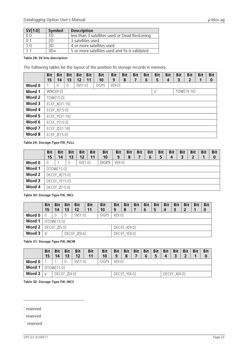
SV[1:0] Symbol Description 0�0� 1D� less�than�3�satellites�used�or�Dead�Reckoning�0�1� 2D� 3�satellites�used�1�0� 3D� 4�or�more�satellites�used�1�1� 3D+� 5�or�more�satellites�used�and�fix�is�validated�
Table 28: SV bits description
The�following�tables�list�the�layout�of�the�position�fix�storage�records�in�memory.�
�Bit 15
Bit 14
Bit 13
Bit 12
Bit 11
Bit 10
Bit 9
Bit 8
Bit 7
Bit 6
Bit 5
Bit 4
Bit 3
Bit 2
Bit 1
Bit 0
Word 0 1� 0� 0� SV[1:0]� DGPS� V[9:0]�
Word 1 WNO[9:0]� x8
� TOW[19:16]�
Word 2 TOW[15:0]�
Word 3 ECEF_X[31:16]�
Word 4 ECEF_X[15:0]�
Word 5 ECEF_Y[31:16]�
Word 6 ECEF_Y[15:0]�
Word 7 ECEF_Z[31:16]�
Word 8 ECEF_Z[15:0]�
Table 29: Storage Type FIX_FULL
�Bit 15
Bit 14
Bit 13
Bit 12
Bit 11
Bit 10
Bit 9
Bit8
Bit 7
Bit 6
Bit 5
Bit 4
Bit 3
Bit 2
Bit 1
Bit 0
Word 0 0� 1� 0� SV[1:0]� DGPS V[9:0]�
Word 1 DTOW[15:0]�
Word 2 DECEF_X[15:0]�
Word 3 DECEF_Y[15:0]�
Word 4 DECEF_Z[15:0]�
Table 30: Storage Type FIX_INCL
�Bit 15
Bit 14
Bit 13
Bit 12
Bit 11
Bit 10
Bit 9
Bit 8
Bit 7
Bit 6
Bit 5
Bit 4
Bit 3
Bit 2
Bit 1
Bit 0
Word 0 0� 0� 0� SV[1:0]� DGPS� V[9:0]�
Word 1 DTOW[15:0]�
Word 2 DECEF_Z[5:0]� DECEF_X[9:0]�
Word 3 X9
� DECEF_Z[9:6]� DECEF_Y[9:0]�
Table 31: Storage Type FIX_INCM
�Bit 15
Bit 14
Bit 13
Bit 12
Bit 11
Bit 10
Bit 9
Bit 8
Bit 7
Bit 6
Bit 5
Bit 4
Bit 3
Bit 2
Bit 1
Bit 0
Word 0 1� 1� 0� SV[1:0]� DGPS� V[9:0]�
Word 1 DTOW[15:0]�
Word 2 x10
� DECEF_Z[4:0]� DECEF_Y[4:0]� DECEF_X[4:0]�
Table 32: Storage Type FIX_INCS
���������������������������������������������������
8
�reserved�
9
�reserved�
10
�reserved�

Datalogging�Option�User’s�Manual� � µ-blox�ag�
GPS.G1-X-00011� � Page�23�
5.5.3 GPIO Storage Records
The�logging�option�has�different�kinds�of�GPIO�storage�records.�The�following�parameters�are�stored:��
Field name Size Description Unit WNO� 10�Bit� Week�Number�(in�GPS�notation)� Week�TOW� 20�Bit� Time�of�Week�(in�GPS�notation)� Seconds�DTOW� 16�Bit� Difference�between�last�and�current�TOW� Seconds�GPIO� 12�Bit� Values�of�the�GPIO�Pins�11�to�0� �
Table 33: GPIO logging parameters
The�following�tables�list�the�layout�of�the�GPIO�storage�recods�in�memory.��
�Bit 15
Bit 14
Bit 13
Bit 12
Bit 11
Bit 10
Bit 9
Bit 8
Bit 7
Bit 6
Bit 5
Bit 4
Bit 3
Bit 2
Bit 1
Bit 0
Word�0� 1� 0� 1� x� GPIO[11:0]�
Word�1� WNO[9:0]� x11
� TOW[19:16]�
Word�2� TOW[15:0]�
Table 34: Storage Type GPIO_FULL
�Bit 15
Bit 14
Bit 13
Bit 12
Bit 11
Bit 10
Bit 9
Bit 8
Bit 7
Bit 6
Bit 5
Bit 4
Bit 3
Bit 2
Bit 1
Bit 0
Word 0 0� 1� 1� X� GPIO[11:0]�
Word 1 DTOW[15:0]�
Table 35: Storage Type GPIO_INC
5.5.4 ESCAPE Type Storage Records
ESCAPE�type�storage�records�are�defined�for�future�use�of�the�logging�firmware.�They�have�a�flexible�format.�Its�size�can�be�determined�by�the�second�byte�(SIZE�field).�
For�example�diagnostics�strings�may�be�written�to�the�flash�memory�as�ESCAPE_TYPE�0x1F�with�a�string�as�the�payload.��
The�following�table�lists�the�layout�of�the�escape�storage�records�in�the�memory.��
�Bit 15
Bit 14
Bit 13
Bit 12
Bit 11
Bit 10
Bit 9
Bit 8
Bit 7
Bit 6
Bit 5
Bit 4
Bit 3
Bit 2
Bit 1
Bit 0
Word 0 0� 0� 1� ESCAPE_TYPE� SIZE�(n�Words)�
Word 1 Payload�
Word .. Payload�
Word .. Payload�
Word n Payload�
Table 36: Storage Type ESCAPE
5.6 Decompressing a downloaded memory block
The�algorithm�decompresses�a�previously�downloaded�memory�block.�
-- Download the data from the GPS receiver flash.
-- Use the logging protocol extension.
-- Get the first storage record into Data.
-- Decompress all storage records while we have Data.
WHILE (Data)
���������������������������������������������������
11
�reserved�

Datalogging�Option�User’s�Manual� � µ-blox�ag�
GPS.G1-X-00011� � Page�24�
-- Now decode the storage record -- Get the Type bits of the storage record.
IF (Type = EMPTY) THEN
-- No data , just skip this word. ELSE IF (Type = FIX_FULL) THEN
-- Save WNO and DTOW fields as the position fix logging time stamp
-- Save the position , speed and the other mode flags ELSE IF ((Type = FIX_INCL) OR (Type = FIX_INCM) OR (Type = FIX_INCS)) THEN
-- Add the DTOW field to the last position fix logging time stamp. -- Add the DECEF to the last position.
-- Save the speed and the other mode flags. ELSE IF (Type = GPIO_FULL) THEN
-- Save WNO and DTOW fields as the GPIO logging time stamp. -- Save the GPIO values. ELSE IF (Type = GPIO_INC) THEN
-- Add the DTOW field to the last GPIO logging time stamp.
-- Save the gpio values. ELSE IF (Type = ESCAPE) THEN
-- Handle the additional ESCAPE type storage records. END IF
-- The size of each storage record can be determined from the type
-- and if it is an escape type from the additional size field.
-- Get the next storage record into Data.
END WHILE

Datalogging�Option�User’s�Manual� � µ-blox�ag�
GPS.G1-X-00011� � Page�25�
6 TRANSFERRING LOGGED DATA USING U-LOGGER.EXE
The�µ-logger�is�a�simple�program�to�demonstrate�and�evaluate�the�logging�capabilities�of�the�µ-blox�GPS�logging�firmware�and�the�protocol�extension.� It�allows�to�configure�the�module�and�to�download�or�erase�the� logged�data.� The� logged� data� may� be� stored� in� various� formats� that� can� be� post� processed� by� using� third� party�programs.��
The�program�runs�on� IBM�compatible�PCs� running�Microsoft�Windows�95/98�or�Microsoft�Windows�NT�4.� It�needs� an� unused� serial� port� where� the� µ-blox� GPS� receiver� is� connected.� The� status� bar� shows� the� actual�connection�and�its�current�status.�It�also�indicates�the�step�and�progress�of�the�current�operation.�The�user�may�abort�any�operation�by�pressing�the�Cancel�button.��
! Note� All� programs� settings� are� stored� in� the� File� u-blox.ini� under� the� section� µ-logger� in� your�windows�directory.�
6.1 Setup the communication
For�changing�settings�and�downloading� logged�data,�a�communication�between�the�GPS�receiver�and�host�PC�with�µ-logger�has�to�be�created.�The�window�‘Connection’�is�used�to�set�up�a�connection.�
�
Figure 5: Setup Communication Window
Figure�5�shows�the�possibilities�of�settings�for�the�serial�interface.�The�communications�port�can�be�selected�from�the�‘Serial�Port’�pulldown�menu.�If�a�port�is�not�in�the�port�list,�another�program�is�still�connected�with�your�GPS.�Close�the�connection�and�then�press�the�‘Refresh�port�list’�button.�The�port�should�now�appear�in�the�port�list.�
The�appropriate�baud�rate�may�be�selected�by�the�‘Baud�rate�[bps]’�pull�down�menu.�The�default�baud�rate�is�19200.�
The� µ-logger� expects� a� response� from� the�GPS� receiver�within� the� timeout� value.� The� default� is� 2000�ms,� it�should�be�suitable�for�most�applications.�
! Note� The�Auto�detect�button�checks�all� serial�ports�and�baud� rates� for�a�connected�GPS.� If� this�does�not�detect� the� GPS,�make� sure� that� it� uses� the� SiRF� binary�mode� protocol� and,� that� the� cables� are� properly�connected.��

Datalogging�Option�User’s�Manual� � µ-blox�ag�
GPS.G1-X-00011� � Page�26�
6.2 Configure the GPS logging parameters
For�an�optimised�storage,�several�different�parameters�may�be�adjusted.�Therefore�the�window�with�the�different�sub�pages�serves�for�this�purpose.�For�additional�information�please�consult�the�“System�Overview”�chapter.�
! Note:�You�must�set�or�get�the�configuration�for�each�sub�tab�separately.��
The� Set configuration� button� stores� the� parameters� selected� in� the� dialog� box� to� the� module.� The� Get configuration�button�reads�out�the�configuration�parameters�from�the�module�and�fills�them�into�the�dialog�box.�
�
6.3 General logging configuration
The�Datalogger�contains�two�main� logging�functionalities:�position�fix�and�GPIO� logging.�The�general� logging�configurations�affects�both�functionalities.�
�
Figure 6: General Logging Configure
The�‘Logging�enabled�checkbox�allows�an�On/Off�switch�of�the�whole�Datalogger.�By�default�the�Datalogger�is�enabled.�
If�the�‘Logging�debug�messages’�flag�is�set,�the�GPS�receiver�transmits�the�logging�debug�messages�within�the�SiRF�binary�Protocols.�That�means:�additional�messages�are�output.�By�default�it�is�disabled.�
If�the�‘Flash�1�PPS�LED�when�logging’�flag�is�set,�the�LED�indicates�a�logging�cycle.�By�default�it�is�disabled�and�the�LED�flashes�at�the�measurement�cycle.�
‘Log�diagnostic�strings’�is�useful�to�store�important�events�like�Reset�into�the�flash.�By�default�it�is�disabled.�
! Note:�If�the�Logging�isn’t�enabled,�the�GPS�receiver�will�not�store�any�records,�regardless�of�other�flags.��
�
6.3.1 Position fix logging configuration
The� ‘Position� fix� logging’� window� contains� the� Position� Fix� Filter� settings.� The� chapter� “Position� Fix� Filter”�explains�this�in�depth.�

Datalogging�Option�User’s�Manual� � µ-blox�ag�
GPS.G1-X-00011� � Page�27�
�
Figure 7: Position Fix Logging Configuration Window
The�‘Position�Fix� logging�enable’�checkbox�allows�an�On/Off�switch�of�the�Position�Fix�Logger.�By�default� it� is�enabled.�
The�Datalogger�allows�different� storage� formats.�The� ‘Store� full� fixes�only’� checkbox�disables� the� incremental�storage� technology.� It� is� not� useful� for� small� storage� resources.� By� default� the� flag� ‘Store� full� fixes� only’� is�disabled.�
If�you�only�want�to�log�the�speed�over�ground�as�velocity�instead�of�the�absolute�speed�of�all�three�dimensions,�the�flag�‘Speed�over�ground’�has�to�be�enabled.�By�default�this�flag�is�disabled.�
The� message� 2� (Navigation� Measurement� Data� Out)� of� the� SiRF� binary� protocol� can� be� suppressed� by� the�checkbox.�By�default�this�message�is�sent.�
If� you� only�want� to� log�when�3D�position� fixes� are� calculated,� the� 4SV� solution� filter� has� to� be� enabled.� By�default�it�is�enabled.�
The�time,�distance�and�speed�filter�values�are�described�in�chapters�“Position�Fix�Filter”�and�“Default�settings�of�the�datalogger”.�
�

Datalogging�Option�User’s�Manual� � µ-blox�ag�
GPS.G1-X-00011� � Page�28�
6.3.2 GPIO logging configuration
GPIO�logging�is�more�difficult�to�configure�since�it�interacts�with�the�hardware�connected�to�the�GPIO�pins.�The�GPS�has�no�knowledge�of�what�components�are�connected,�and�therefore�has�no�way�to�find�out�which�signals�are�driven�by�external�components�and�which�can�be�driven�by�the�GPS�itself.��
! Note:�You�have�to�make�sure�that�the�GPS�module�and�its�surrounding�electronics�don't�drive�signal�lines�at�the�same�time.�Improper�use�can�lead�to�permanent�damage�to�the�system!��
The�GPS�is�configured�by�bit�masks,�which�are�represented�by�the�checkboxes�in�the�dialog�box.��
�
Figure 8: GPIO Logging Configuration Window
Figure�8�shows�the�GPIO�Logging�Configuration�Window.�This�window�contains�general�GPIO�settings�and�GPIO�logging�settings.�
�
The� GPIO� logging� settings� control� the� GPIO� logging.� The� ‘GPIO� logging� enable’� checkbox� allows� an� On/Off�switch�of�the�GPIO�Logger.�By�default�it�is�disabled.�The�‘Store�full�fixes�only’�checkbox�disables�the�incremental�storage� technology.� The� chapters� “GPIO� Filter”� and� “Default� settings� of� the� datalogger”� contain� a� detailed�description�of�these�settings.��
�
The�general�GPIO�settings�allow�the�user�to�adjust�the�pin�function�according�to�the�application�requirements.�

Datalogging�Option�User’s�Manual� � µ-blox�ag�
GPS.G1-X-00011� � Page�29�
Apply
to pin?
Pin is
output?
Output
is high?
set output to
VCC
set output to
Gnd
END
Yes
Yes
Yes
No
No
No
set to outputset to input
�
Figure 9: General GPIO settings
Figure�9�describes�dependencies�on�the�checkboxes�for�configuring�a�GPIO�pin.�This�applies�to�all�12�GPIO�pins.�
�
! Note:��The�checkbox�‘Apply�to�pin’�has�to�be�enabled�for�each�GPIO�in�order�to�the�change�a�pin’s�settings�and�enables�its�pin�logging�capability.�
�

Datalogging�Option�User’s�Manual� � µ-blox�ag�
GPS.G1-X-00011� � Page�30�
6.4 Download or erase the logged data
During� GPS� processing,� data� is� stored� in� the� flash�memory� of� the� GPS�module.� This�Window�allows� you� to�download�or�erase�the�logged�data.�You�can�choose�the�file�formats�in�which�the�data�is�stored�on�your�PC.�
The�data� logger�works�only� if� the� flash�memory�has� free� space.�Thus� it�has� to�be�possible� to�erase� the� flash�memory�on�the�GPS�module.�Erasing�takes�place�after�download�of�logged�data�or�separately.�
�
Figure 10: Download-Erase Data Window
Figure�10�shows�the�download�and�erase�window.�The�following�settings�are�possible:�
�� Selection�of�appropriate�file�format.�Please�note,�that�the�NMEA�formats�contain�only�information�of�the�Position�Fix�storage�records.�
�� Selection�of�path�and�filename,�where�you�want�to�store�the�File.�You�can�press�the�button�next�to�the�edit�box�to�select�the�path�and�filename.�
�� If�you�want�to�automatically�erase�the�logged�data�after�download�tick�the�check�box.�
�� Click�the�Download�button�to�download�and�store�the�data�on�the�disk.�
�� Note:�The�Erase�button�deletes�the�flash�area�reserved�for�data�logging.�
�
The�following�table�describes�the�possible�file�formats�in�which�the�data�can�be�stored�on�you�PC.�

Datalogging�Option�User’s�Manual� � µ-blox�ag�
GPS.G1-X-00011� � Page�31�
Type Description Binary� Compressed�data�as�in�the�flash,�saved�binary,�bigendian�byte�order�NMEA� Decompressed�data,�saved�as�NMEA�GLL,�RMC,�GGA�and�VTG�messages�NMEA�GLL� Decompressed�data,�saved�as�NMEA�GLL�messages�NMEA�RMC� Decompressed�data,�saved�as�NMEA�RMC�messages�NMEA�GGA� Decompressed�data,�saved�as�NMEA�GGA�messages�NMEA�VTG� Decompressed�data,�saved�as�NMEA�VTG�messages�Text� Decompressed�data,�saved�as�ASCII�text,�All�data�Text�FIX� Decompressed�data,�saved�as�tabular�ASCII�text,�Fix�data�only�Text�GPIO� Decompressed�data,�saved�as�tabular�ASCII�text,�GPIO�data�only�
Table 37: Download file formats
�
6.5 Conversion of logged data
The�logged�data�is�transmitted�within�SiRF�binary�message�only.�The�logged�data�is�stored�into�a�file�on�PC�with�the�defined�format.�The�µ-logger�offers�the�possibility�to�convert�binary�download�files�into�all�other�described�download�formats.�
�
Figure 11: Convert Window
This�picture�shows�the�Convert�Window.�The�file�to�be�converted�has�to�be�filled�into�the�field�‘Convert�File’.�The�‘File�Format’�describes�the�format�of�the�resulting�file.�The�field�‘Save�as’�describes�the�destination�file�to�hold�the�converted�data.�
! Note:��This�enables�you�to�convert�the�downloaded�data�of�a�binary�file�into�the�different�formats.�The�Data�Logger�does�not�need�to�be�connected�while�converting.�
�

Datalogging�Option�User’s�Manual� � µ-blox�ag�
GPS.G1-X-00011� � Page�32�
6.6 Fix Logging Performance Example
Assume�that�the�Fix�logging�parameters�are��
T_min = 5[s]
T_max = 3600[s]
D_Delta = 150[m]
�
The�logging�time�depends�on�the�memory�available�for�logging�and�on�how�the�receiver�is�moved.�The�µ-blox�GPS�receivers�have�1`024�kBytes�(8�MBits)�of�flash�memory�of�which�640�kBytes
12
�may�be�used�for�logging.�The�following�equation�calculates�how�long�data�can�be�logged.��
�����������record�storage�per�size
memory�flash�freestorage�between�timetime�logging ��
�
The�worst�case�is�that�we�would�have�to�store�a�logging�record�in�FIX_FULL�format�every�second.�The�logging�time�will�be�around�2�days�(10�hours�if�the�T_min�filter�is�not�active).�
Let's� assume� that�we� are� constantly� traveling�with� 50� km/h� (14�m/s).� The� time� between� storage�will� be� 11�seconds.�Since�we�moved�about�150�meters�the�data� is�most�probably�stored� in�the�FIX_INCM�storage�record�format.�The�calculated�logging�time�is�more�than�8�days.�
6.6.1 Real Example
This�example�shows�a�short�ride�with�a�car.�Table�38�lists�the�configuration�used�in�this�example.�No�differential�GPS�was�connected.��
Parameter Value Flags� 0x01�T_min� 2�[s]�T_max� 3600[s]�D_delta� 50�[m]�
Table 38: Module fix logging configuration
The�following�lines�show�an�extract�of�a�hexadecimal�dump�of�the�file�saved�in�binary�format.��
000001a0: .... 1831 0003 73e3 03fe 1836 0003 7be1
000001b0: 03fc 1835 0003 83df 03ff 1836 0003 87e2
000001c0: 03fc 1833 0003 83e0 03fd 1838 0003 7be2
000001d0: 03fe 182e 0003 7fe4 0001 1828 0003 73e6
000001e0: 03fe 1819 0005 77e4 0003 182c 0004 73dd
000001f0: 03fd 1816 0004 53e1 0000 1824 0006 bc10
00000200: 3c22 1821 0003 b412 3c12 1813 0004 b80e
00000210: 3c17 1816 0006 c00c 3c21 181e 0005 c80c
00000220: 3c1f 1827 0003 c40c 3c1a 1827 0003 b80b
00000230: 3c1d 1824 0003 c00a 3c1d 1818 0004 c40b
00000240: 3c1d ....
�
The�following�lines�show�an�extract�of�the�data�saved�as�a�tabular�text.��
���������������������������������������������������
12
�GPS-PS1E��512�kBytes�(4�MBits)�of�flash�memory�of�which�128�kBytes�are�free.�

Datalogging�Option�User’s�Manual� � µ-blox�ag�
GPS.G1-X-00011� � Page�33�
FIX_Type FIX DGPS WNO TOW DTOW Time Date Decef_X Decef_Y Decef_Z Ecef_X Ecef_Y Ecef_Z Speed Longitude Latitude Altitude
FIX_INCM 3D+ No 999 120495 3 09:28:15 03/01/1999 29 2 28 4278899 643178 4670897 49 8.548354 47.380770 418
FIX_INCM 3D+ No 999 120498 3 09:28:18 03/01/1999 31 4 30 4278868 643174 4670927 54 8.548363 47.381159 419
FIX_INCM 3D+ No 999 120501 3 09:28:21 03/01/1999 33 1 32 4278835 643173 4670959 53 8.548415 47.381571 420
FIX_INCM 3D+ No 999 120504 3 09:28:24 03/01/1999 30 4 33 4278805 643169 4670992 54 8.548421 47.381972 424
FIX_INCM 3D+ No 999 120507 3 09:28:27 03/01/1999 32 3 32 4278773 643166 4671024 51 8.548445 47.382380 426
FIX_INCM 3D+ No 999 120510 3 09:28:30 03/01/1999 30 2 30 4278743 643164 4671054 56 8.548478 47.382761 427
FIX_INCM 3D+ No 999 120513 3 09:28:33 03/01/1999 28 1 31 4278715 643165 4671085 46 8.548546 47.383132 432
FIX_INCM 3D+ No 999 120516 3 09:28:36 03/01/1999 26 2 28 4278689 643163 4671113 40 8.548571 47.383474 435
FIX_INCM 3D+ No 999 120521 5 09:28:41 03/01/1999 28 3 29 4278661 643166 4671142 25 8.548666 47.383831 437
FIX_INCM 3D+ No 999 120525 4 09:28:45 03/01/1999 35 3 28 4278626 643163 4671170 44 8.548695 47.384234 434
FIX_INCM 3D+ No 999 120529 4 09:28:49 03/01/1999 31 0 20 4278595 643163 4671190 22 8.548756 47.384558 428
FIX_INCM 3D+ No 999 120535 6 09:28:55 03/01/1999 16 34 17 4278611 643197 4671173 36 8.549170 47.384317 430
FIX_INCM 3D+ No 999 120538 3 09:28:58 03/01/1999 18 18 19 4278629 643215 4671154 33 8.549370 47.384065 430
FIX_INCM 3D+ No 999 120542 4 09:29:02 03/01/1999 14 23 18 4278643 643238 4671136 19 8.549644 47.383842 428
FIX_INCM 3D+ No 999 120548 6 09:29:08 03/01/1999 12 33 16 4278655 643271 4671120 22 8.550052 47.383633 428
FIX_INCM 3D+ No 999 120553 5 09:29:13 03/01/1999 12 31 14 4278667 643302 4671106 30 8.550435 47.383439 429
FIX_INCM 3D+ No 999 120556 3 09:29:16 03/01/1999 12 26 15 4278679 643328 4671091 39 8.550752 47.383243 428
FIX_INCM 3D+ No 999 120559 3 09:29:19 03/01/1999 11 29 18 4278690 643357 4671073 39 8.551110 47.383033 425
FIX_INCM 3D+ No 999 120562 3 09:29:22 03/01/1999 10 29 16 4278700 643386 4671057 36 8.551470 47.382842 423
FIX_INCM 3D+ No 999 120566 4 09:29:26 03/01/1999 11 29 15 4278711 643415 4671042 24 8.551828 47.382650 422
�
Third�party�software�can�be�used�to�overlay�decoded�logging�data�onto�a�map.�Figure�12�shows�an�example�of�such�overlaying�techniques.�
�
Figure 12: Short ride represented on a map

Datalogging�Option�User’s�Manual� � µ-blox�ag�
GPS.G1-X-00011� � Page�34�
7 RELATED DOCUMENTS
GPS.G1-MS1-00002�� GPS-MS1E�Datasheet�
GPS.G1-PS1-00002�� GPS-PS1E�Datasheet�
GPS.G1-X-00005� GPS-MS1E/GPS-PS1E�Protocol�Specification�
GPS.G1-X-00002�� Update�Manual�
�
All�these�documents�are�available�on�our�homepage�(http://www.u-blox.com).�

Datalogging�Option�User’s�Manual� � µ-blox�ag�
GPS.G1-X-00011� � Page�35�
A GLOSSARY
DGPS� Differential�GPS�FLASH� No�Volatile�Memory�Chip�GPIO� General�Purpose�Input�/�Output�GPS� Global�Positioning�System�NMEA� Special�GPS�Protocol�Format�MID� Message�Identifier�(of�a�Protocol)�PC� Personal�Computer�SV� Space�Vehicle��(Satellite)�TOW� Time�of�Week�(GPS�Time)�UART� Asynchronous�Serial�Interface�
Datalogging�Option�User’s�Manual� � µ-blox�ag�
GPS.G1-X-00011� � Page�36�
B CONTACT
For�further�information�contact:�
�
Technical Support Headquarter �µ-blox�ag��Zürcherstrasse�68�CH-8800�Thalwil,�Switzerland��Phone:� +41-1-722�74�74�FAX:� +41-1-722�74�47��E-mail:� [email protected]�WWW:� http://www.u-blox.com�
µ-blox�ag��Zürcherstrasse�68�CH-8800�Thalwil,�Switzerland��Phone:� +41-1-722�74�44�FAX:� +41-1-722�74�47��E-mail:� [email protected]�WWW:� http://www.u-blox.com�
�
�

Datalogging�Option�User’s�Manual� � µ-blox�ag�
GPS.G1-X-00011� � Page�37�
REVISION HISTORY
�
Revision Index
Date Name Status / Comments
P1� 18.10.00� PE� Initial�Version�
P2� 30.10.00� JR� Release�Candidate�
� 02.11.00� JR,�MA� Public�Release��
� � � �
�
�
All�trademarks�mentioned�in�this�document�are�property�of�their�respective�owners.�
�
Copyright�©�2000,�µ-blox�ag�
�
This�data�sheet�contains�information�on�µ-blox�products�in�the�sampling�and�initial�production�phases�of�development.�The�specifications�inthis�data�sheet�are�subject�to�change�at�µ-BLOX'�discretion.�µ-blox�assumes�no�responsibility�for�any�claims or�damages�arising�out�of�the�use�of� this� document,� or� from� the� use� of� modules� based� on� this� document,� including� but� not� limited� to� claims� or� damages� based� on�infringement�of�patents,�copyrights�or�other�intellectual�property�rights.�µ-blox�makes�no�warranties,�either�expressed�or�implied�with�respect�to�the�information�and�specifications�contained�in�this�document.��Performance�characteristics�listed�in�this�document�are�estimates�only�anddo�not�constitute�a�warranty�or�guarantee�of�product�performance.�