Dataliner User Display Manual - · PDF fileALLEN-BRADLEY User Manual Dataliner Message...
186
ALLEN-BRADLEY User Manual Dataliner Message Display DL20 Series Allen-Bradley
Transcript of Dataliner User Display Manual - · PDF fileALLEN-BRADLEY User Manual Dataliner Message...

ALLEN-BRADLEY
UserManual
DatalinerMessageDisplayDL20 Series
Allen-Bradley
Solid state equipment has operational characteristics differing from those ofelectromechanical equipment. “Safety Guidelines for the Application,Installation and Maintenance of Solid State Controls” (Publication SGI-1.1)describes some important differences between solid state equipment andhard–wired electromechanical devices. Because of this difference, and alsobecause of the wide variety of uses for solid state equipment, all personsresponsible for applying this equipment must satisfy themselves that eachintended application of this equipment is acceptable.
In no event will the Allen-Bradley Company be responsible or liable forindirect or consequential damages resulting from the use or application ofthis equipment.
The examples and diagrams in this manual are included solely for illustrativepurposes. Because of the many variables and requirements associated withany particular installation, the Allen-Bradley Company cannot assumeresponsibility or liability for actual use based on the examples and diagrams.
No patent liability is assumed by Allen-Bradley Company with respect to useof information, circuits, equipment, or software described in this manual.
Reproduction of the contents of this manual, in whole or in part, withoutwritten permission of the Allen-Bradley Company is prohibited.
Throughout this manual we use notes to make you aware of safetyconsiderations.
!ATTENTION: Identifies information about practices orcircumstances that can lead to personal injury or death, propertydamage, or economic loss.
Attentions help you:
• identify a hazard
• avoid the hazard
• recognize the consequences
Important: Identifies information that is especially important for successfulapplication and understanding of the product.
PLC and Dataliner are registered trademarks of Allen-Bradley Company, Inc.
Important User Information

A–BDataliner Message DisplayDL20 Series
Table of Contents
i
Chapter 1Chapter Objectives 1–1. . . . . . . . . . . . . . . . . . . . . . . . . . . . . . . . . . . . . . . Manual Overview 1–1. . . . . . . . . . . . . . . . . . . . . . . . . . . . . . . . . . . . . . . Intended Audience 1–2. . . . . . . . . . . . . . . . . . . . . . . . . . . . . . . . . . . . . . . Conventions Used 1–2. . . . . . . . . . . . . . . . . . . . . . . . . . . . . . . . . . . . . . . Related Publications 1–2. . . . . . . . . . . . . . . . . . . . . . . . . . . . . . . . . . . . .
Chapter 2Chapter Objectives 2–1. . . . . . . . . . . . . . . . . . . . . . . . . . . . . . . . . . . . . . . Overview of DL20 2–1. . . . . . . . . . . . . . . . . . . . . . . . . . . . . . . . . . . . . . .
Message Editing Software 2–2. . . . . . . . . . . . . . . . . . . . . . . . . . . . . . . Optional Offline Programming Software 2–2. . . . . . . . . . . . . . . . . . . Storing Messages 2–2. . . . . . . . . . . . . . . . . . . . . . . . . . . . . . . . . . . . . .
Host and Slave Devices 2–3. . . . . . . . . . . . . . . . . . . . . . . . . . . . . . . . . . . Addressable Master 2–3. . . . . . . . . . . . . . . . . . . . . . . . . . . . . . . . . . . . Slave Mode Master 2–3. . . . . . . . . . . . . . . . . . . . . . . . . . . . . . . . . . . . Programmable Controller Interface 2–3. . . . . . . . . . . . . . . . . . . . . . . . Auxiliary Devices 2–4. . . . . . . . . . . . . . . . . . . . . . . . . . . . . . . . . . . . .
Self Testing and Diagnostics 2–4. . . . . . . . . . . . . . . . . . . . . . . . . . . . . . . Power On Testing 2–4. . . . . . . . . . . . . . . . . . . . . . . . . . . . . . . . . . . . . . Autorun 2–4. . . . . . . . . . . . . . . . . . . . . . . . . . . . . . . . . . . . . . . . . . . . . CPU ACTIVE Light 2–4. . . . . . . . . . . . . . . . . . . . . . . . . . . . . . . . . . .
Message Options 2–5. . . . . . . . . . . . . . . . . . . . . . . . . . . . . . . . . . . . . . . . Communications Options 2–5. . . . . . . . . . . . . . . . . . . . . . . . . . . . . . . . . Accessories 2–6. . . . . . . . . . . . . . . . . . . . . . . . . . . . . . . . . . . . . . . . . . . .
Chapter 3Chapter Objectives 3–1. . . . . . . . . . . . . . . . . . . . . . . . . . . . . . . . . . . . . . . Desktop Hookup 3–1. . . . . . . . . . . . . . . . . . . . . . . . . . . . . . . . . . . . . . . . Initial Startup 3–3. . . . . . . . . . . . . . . . . . . . . . . . . . . . . . . . . . . . . . . . . . . Types of Prompts 3–4. . . . . . . . . . . . . . . . . . . . . . . . . . . . . . . . . . . . . . . .
Yes/No Prompts 3–4. . . . . . . . . . . . . . . . . . . . . . . . . . . . . . . . . . . . . . . Numeric Prompts 3–5. . . . . . . . . . . . . . . . . . . . . . . . . . . . . . . . . . . . . .
Main Menu 3–6. . . . . . . . . . . . . . . . . . . . . . . . . . . . . . . . . . . . . . . . . . . . . Returning to Main Menu 3–6. . . . . . . . . . . . . . . . . . . . . . . . . . . . . . . . . .
Using This Manual
Introduction to the DL20
Getting Started
Dataliner Message DisplayDL20 Series
Table of Contents
ii
Chapter 4Chapter Objectives 4–1. . . . . . . . . . . . . . . . . . . . . . . . . . . . . . . . . . . . . . . Entering the Editor 4–1. . . . . . . . . . . . . . . . . . . . . . . . . . . . . . . . . . . . . . . Specifying Message Attributes 4–3. . . . . . . . . . . . . . . . . . . . . . . . . . . . .
Line Selection 4–3. . . . . . . . . . . . . . . . . . . . . . . . . . . . . . . . . . . . . . . . Line-Scroll Mode 4–4. . . . . . . . . . . . . . . . . . . . . . . . . . . . . . . . . . . . . . Printing Messages 4–4. . . . . . . . . . . . . . . . . . . . . . . . . . . . . . . . . . . . . Slave Messages 4–5. . . . . . . . . . . . . . . . . . . . . . . . . . . . . . . . . . . . . . . Message Wait Time 4–5. . . . . . . . . . . . . . . . . . . . . . . . . . . . . . . . . . . . Auto Clear 4–6. . . . . . . . . . . . . . . . . . . . . . . . . . . . . . . . . . . . . . . . . . . Auto Repeat 4–6. . . . . . . . . . . . . . . . . . . . . . . . . . . . . . . . . . . . . . . . . . Chaining Messages 4–7. . . . . . . . . . . . . . . . . . . . . . . . . . . . . . . . . . . . Flashing Messages 4–9. . . . . . . . . . . . . . . . . . . . . . . . . . . . . . . . . . . . . Relay Operation 4–9. . . . . . . . . . . . . . . . . . . . . . . . . . . . . . . . . . . . . . . Historical Event Recording 4–10. . . . . . . . . . . . . . . . . . . . . . . . . . . . . . Invisible Messages 4–10. . . . . . . . . . . . . . . . . . . . . . . . . . . . . . . . . . . . .
Attribute Defaults 4–10. . . . . . . . . . . . . . . . . . . . . . . . . . . . . . . . . . . . . . . Editing Messages 4–11. . . . . . . . . . . . . . . . . . . . . . . . . . . . . . . . . . . . . . . . Edit Commands 4–11. . . . . . . . . . . . . . . . . . . . . . . . . . . . . . . . . . . . . . . . . Moving the Cursor 4–12. . . . . . . . . . . . . . . . . . . . . . . . . . . . . . . . . . . . . . .
Move Cursor Forward One Space (Ctrl L) 4–12. . . . . . . . . . . . . . . . . . Move Cursor Backward One Space (Ctrl H) 4–12. . . . . . . . . . . . . . . . . Move Cursor Up One Line (Ctrl K) 4–12. . . . . . . . . . . . . . . . . . . . . . . Move Cursor Down One Line (Ctrl J) 4–12. . . . . . . . . . . . . . . . . . . . . .
Deleting a Character (Ctrl D) 4–13. . . . . . . . . . . . . . . . . . . . . . . . . . . . . . Erasing a Message (Ctrl E) 4–13. . . . . . . . . . . . . . . . . . . . . . . . . . . . . . . . Setting New Message Attributes (Ctrl A) 4–14. . . . . . . . . . . . . . . . . . . . . Previewing a Message (Ctrl R) 4–14. . . . . . . . . . . . . . . . . . . . . . . . . . . . . Imbedding Variable Data (Ctrl V) 4–15. . . . . . . . . . . . . . . . . . . . . . . . . . . Imbedding Formatted Variable with Decimal Point (Ctrl X) 4–15. . . . . . Changing Variable Format (Ctrl C) 4–16. . . . . . . . . . . . . . . . . . . . . . . . . . Imbedding Time and Date (Ctrl T) 4–17. . . . . . . . . . . . . . . . . . . . . . . . . . Showing Available Memory (Ctrl F) 4–17. . . . . . . . . . . . . . . . . . . . . . . . . Uppercase Lock-Unlock (Ctrl U) 4–18. . . . . . . . . . . . . . . . . . . . . . . . . . . Show Commands (Ctrl S) 4–18. . . . . . . . . . . . . . . . . . . . . . . . . . . . . . . . . Exiting the Editor (Ctrl Q) 4–19. . . . . . . . . . . . . . . . . . . . . . . . . . . . . . . . . Entering an Example Message 4–19. . . . . . . . . . . . . . . . . . . . . . . . . . . . . Estimating Memory Usage 4–22. . . . . . . . . . . . . . . . . . . . . . . . . . . . . . . .
Creating and EditingMessages

Dataliner Message DisplaysDL20 Series
Table of Contents
iii
Chapter 5Chapter Objectives 5–1. . . . . . . . . . . . . . . . . . . . . . . . . . . . . . . . . . . . . . . Entering the Run Mode 5–1. . . . . . . . . . . . . . . . . . . . . . . . . . . . . . . . . . . Autorun Feature 5–1. . . . . . . . . . . . . . . . . . . . . . . . . . . . . . . . . . . . . . . . . Autorun Message 5–2. . . . . . . . . . . . . . . . . . . . . . . . . . . . . . . . . . . . . . . . Background Message 5–2. . . . . . . . . . . . . . . . . . . . . . . . . . . . . . . . . . . . . Exiting the Run Mode 5–2. . . . . . . . . . . . . . . . . . . . . . . . . . . . . . . . . . . . Triggers and Queues 5–3. . . . . . . . . . . . . . . . . . . . . . . . . . . . . . . . . . . . . Loading and Unloading Queues 5–3. . . . . . . . . . . . . . . . . . . . . . . . . . . .
Loading Data Queue 5–3. . . . . . . . . . . . . . . . . . . . . . . . . . . . . . . . . . . Loading Message Trigger Queue 5–3. . . . . . . . . . . . . . . . . . . . . . . . . . Unloading Queues 5–4. . . . . . . . . . . . . . . . . . . . . . . . . . . . . . . . . . . . .
Queue Capacity 5–4. . . . . . . . . . . . . . . . . . . . . . . . . . . . . . . . . . . . . . . . . Queuing Examples 5–5. . . . . . . . . . . . . . . . . . . . . . . . . . . . . . . . . . . . . . . Transferring Data to be Queued 5–5. . . . . . . . . . . . . . . . . . . . . . . . . . . . Special Messages 5–6. . . . . . . . . . . . . . . . . . . . . . . . . . . . . . . . . . . . . . . .
Special Message #1: Clear Display 5–6. . . . . . . . . . . . . . . . . . . . . . . . Special Message #2: Clear Display and Queues 5–6. . . . . . . . . . . . . . Special Message #3: Reset DL20 5–7. . . . . . . . . . . . . . . . . . . . . . . . . Special Message #4: Test Battery 5–7. . . . . . . . . . . . . . . . . . . . . . . . . Special Message #5: Print HE Stack 5–7. . . . . . . . . . . . . . . . . . . . . . . Special Message #6: Stop Printing HE Stack 5–8. . . . . . . . . . . . . . . . Special Message #7: Clear HE Stack 5–8. . . . . . . . . . . . . . . . . . . . . . . Special Message #8: Resume Run Mode 5–8. . . . . . . . . . . . . . . . . . . . Special Message #9: Clear Queues, Halt Run Mode 5–9. . . . . . . . . . . Special Message #10: Clear Queues 5–9. . . . . . . . . . . . . . . . . . . . . . . Special Message #11: Test Display 5–9. . . . . . . . . . . . . . . . . . . . . . . . Setting Clock Using Special Messages 5–10. . . . . . . . . . . . . . . . . . . . . Special Message #12: Interactive Clock Setting 5–10. . . . . . . . . . . . . . Special Message #13: Set Clock Using Variable Data 5–11. . . . . . . . . Special Message #15: Enable HE Stack 5–12. . . . . . . . . . . . . . . . . . . . Special Message #16: Disable HE Stack 5–12. . . . . . . . . . . . . . . . . . . .
Dynamic Chaining 5–13. . . . . . . . . . . . . . . . . . . . . . . . . . . . . . . . . . . . . . . Dynamic Chaining Example #1 5–14. . . . . . . . . . . . . . . . . . . . . . . . . . . . . Dynamic Chaining Example #2 5–15. . . . . . . . . . . . . . . . . . . . . . . . . . . . . Illegal Message Trigger Indication 5–16. . . . . . . . . . . . . . . . . . . . . . . . . . Variable Stack Empty Indication 5–16. . . . . . . . . . . . . . . . . . . . . . . . . . . . Printer Handshaking 5–16. . . . . . . . . . . . . . . . . . . . . . . . . . . . . . . . . . . . . Historical Event Recording 5–17. . . . . . . . . . . . . . . . . . . . . . . . . . . . . . . .
Run Mode
Dataliner Message DisplayDL20 Series
Table of Contents
iv
Chapter 6Chapter Objectives 6–1. . . . . . . . . . . . . . . . . . . . . . . . . . . . . . . . . . . . . . . Serial Port Connectors 6–1. . . . . . . . . . . . . . . . . . . . . . . . . . . . . . . . . . . . Serial Data Format 6–2. . . . . . . . . . . . . . . . . . . . . . . . . . . . . . . . . . . . . . . Using the Serial Port 6–2. . . . . . . . . . . . . . . . . . . . . . . . . . . . . . . . . . . . .
Selecting Serial Port Parameters 6–2. . . . . . . . . . . . . . . . . . . . . . . . . . Serial Data Format 6–2. . . . . . . . . . . . . . . . . . . . . . . . . . . . . . . . . . . . . Serial Data Example 6–4. . . . . . . . . . . . . . . . . . . . . . . . . . . . . . . . . . .
Addressable Master 6–5. . . . . . . . . . . . . . . . . . . . . . . . . . . . . . . . . . . . . . Slave Mode 6–6. . . . . . . . . . . . . . . . . . . . . . . . . . . . . . . . . . . . . . . . . . . .
Entering Slave Mode 6–6. . . . . . . . . . . . . . . . . . . . . . . . . . . . . . . . . . . Exiting Slave Mode 6–6. . . . . . . . . . . . . . . . . . . . . . . . . . . . . . . . . . . . Slave Mode Protocol 6–6. . . . . . . . . . . . . . . . . . . . . . . . . . . . . . . . . . . Slave Mode Control Codes 6–7. . . . . . . . . . . . . . . . . . . . . . . . . . . . . . Slave Mode Baud Rate 6–7. . . . . . . . . . . . . . . . . . . . . . . . . . . . . . . . . Slave Mode Individual Relay Control 6–7. . . . . . . . . . . . . . . . . . . . . .
Chapter 7Chapter Objectives 7–1. . . . . . . . . . . . . . . . . . . . . . . . . . . . . . . . . . . . . . . Parallel Port Description 7–1. . . . . . . . . . . . . . . . . . . . . . . . . . . . . . . . . . Using the Parallel Port 7–2. . . . . . . . . . . . . . . . . . . . . . . . . . . . . . . . . . . .
Logic Levels 7–2. . . . . . . . . . . . . . . . . . . . . . . . . . . . . . . . . . . . . . . . . Binary vs. BCD 7–3. . . . . . . . . . . . . . . . . . . . . . . . . . . . . . . . . . . . . . . Data Line Values (Binary) 7–4. . . . . . . . . . . . . . . . . . . . . . . . . . . . . . . Data Line Values (BCD) 7–4. . . . . . . . . . . . . . . . . . . . . . . . . . . . . . . . Parallel Port Strobe Lines 7–5. . . . . . . . . . . . . . . . . . . . . . . . . . . . . . . Edge Triggered Strobe 7–7. . . . . . . . . . . . . . . . . . . . . . . . . . . . . . . . . . Unchanged Data Rejection 7–7. . . . . . . . . . . . . . . . . . . . . . . . . . . . . .
Input Converters 7–8. . . . . . . . . . . . . . . . . . . . . . . . . . . . . . . . . . . . . . . . Parallel Port Sampling Methods 7–8. . . . . . . . . . . . . . . . . . . . . . . . . . . . Event Driven Sampling 7–9. . . . . . . . . . . . . . . . . . . . . . . . . . . . . . . . . . . Time Driven Sampling 7–10. . . . . . . . . . . . . . . . . . . . . . . . . . . . . . . . . . . .
Time Driven Sampling Methods 7–10. . . . . . . . . . . . . . . . . . . . . . . . . . AC Sampling 7–10. . . . . . . . . . . . . . . . . . . . . . . . . . . . . . . . . . . . . . . . . DC Sampling 7–11. . . . . . . . . . . . . . . . . . . . . . . . . . . . . . . . . . . . . . . . .
Transferring Variable Data 7–12. . . . . . . . . . . . . . . . . . . . . . . . . . . . . . . . . Example Message Trigger with Variable Data 7–13. . . . . . . . . . . . . . . . . Reducing Host Output Requirements 7–14. . . . . . . . . . . . . . . . . . . . . . . .
The Serial Port
The Parallel Port

Dataliner Message DisplaysDL20 Series
Table of Contents
v
Chapter 8Chapter Objectives 8–1. . . . . . . . . . . . . . . . . . . . . . . . . . . . . . . . . . . . . . . Special Functions Menu 8–2. . . . . . . . . . . . . . . . . . . . . . . . . . . . . . . . . . Print Messages 8–3. . . . . . . . . . . . . . . . . . . . . . . . . . . . . . . . . . . . . . . . . . Tape Operations 8–5. . . . . . . . . . . . . . . . . . . . . . . . . . . . . . . . . . . . . . . . . Using Data Recorders 8–7. . . . . . . . . . . . . . . . . . . . . . . . . . . . . . . . . . . .
Using Allen-Bradley Data Recorders 8–7. . . . . . . . . . . . . . . . . . . . . . Using STR-Link II and III Data Recorders 8–7. . . . . . . . . . . . . . . . . .
EPROM Programming 8–8. . . . . . . . . . . . . . . . . . . . . . . . . . . . . . . . . . . DL20 Operation Using an EPROM 8–8. . . . . . . . . . . . . . . . . . . . . . . .
Real Time Clock Functions 8–9. . . . . . . . . . . . . . . . . . . . . . . . . . . . . . . . Reset Unit Function 8–11. . . . . . . . . . . . . . . . . . . . . . . . . . . . . . . . . . . . . . Setting Up I/O Port Functions 8–12. . . . . . . . . . . . . . . . . . . . . . . . . . . . . .
Setting Serial Port 8–13. . . . . . . . . . . . . . . . . . . . . . . . . . . . . . . . . . . . Setting Parallel Port 8–15. . . . . . . . . . . . . . . . . . . . . . . . . . . . . . . . . . .
Debug Mode 8–18. . . . . . . . . . . . . . . . . . . . . . . . . . . . . . . . . . . . . . . . . . . Clear RAM 8–18. . . . . . . . . . . . . . . . . . . . . . . . . . . . . . . . . . . . . . . . . . . . . Set Up Master 8–19. . . . . . . . . . . . . . . . . . . . . . . . . . . . . . . . . . . . . . . . . .
Selecting an Autorun Message 8–20. . . . . . . . . . . . . . . . . . . . . . . . . . . Selecting a Background Message 8–20. . . . . . . . . . . . . . . . . . . . . . . . . Selecting a Master Address 8–21. . . . . . . . . . . . . . . . . . . . . . . . . . . . . . Enable Dynamic Chaining 8–22. . . . . . . . . . . . . . . . . . . . . . . . . . . . . . . Turn Relay On When Batteries are Low 8–22. . . . . . . . . . . . . . . . . . . . Displaying Prompts on All Slaves 8–23. . . . . . . . . . . . . . . . . . . . . . . . . Flagging Errors 8–23. . . . . . . . . . . . . . . . . . . . . . . . . . . . . . . . . . . . . . .
Chapter 9Chapter Objectives 9–1. . . . . . . . . . . . . . . . . . . . . . . . . . . . . . . . . . . . . . . Installation Dimensions 9–1. . . . . . . . . . . . . . . . . . . . . . . . . . . . . . . . . . . DL20 Installation 9–1. . . . . . . . . . . . . . . . . . . . . . . . . . . . . . . . . . . . . . . .
Mounting Procedure 9–1. . . . . . . . . . . . . . . . . . . . . . . . . . . . . . . . . . . Wiring Procedures 9–2. . . . . . . . . . . . . . . . . . . . . . . . . . . . . . . . . . . . . DL20 Wiring Terminals 9–3. . . . . . . . . . . . . . . . . . . . . . . . . . . . . . . . .
Connecting RS-232 Devices 9–5. . . . . . . . . . . . . . . . . . . . . . . . . . . . . . . Connecting IBM XT or Compatible 9–5. . . . . . . . . . . . . . . . . . . . . . . Connecting IBM AT or Compatible 9–5. . . . . . . . . . . . . . . . . . . . . . . Connecting 1775-GA Peripheral Communications Module 9–6. . . . . Connecting 1771-DB BASIC Module 9–6. . . . . . . . . . . . . . . . . . . . . . Connecting a Data Recorder 9–7. . . . . . . . . . . . . . . . . . . . . . . . . . . . . Connecting a Programming Terminal 9–7. . . . . . . . . . . . . . . . . . . . . .
Connecting RS-422 Devices 9–9. . . . . . . . . . . . . . . . . . . . . . . . . . . . . . . Connecting DL10 Slaves 9–9. . . . . . . . . . . . . . . . . . . . . . . . . . . . . . . . Connecting Addressable DL20 Masters 9–10. . . . . . . . . . . . . . . . . . . . Connecting 1771-DB BASIC Module to a Single DL20 9–11. . . . . . . Connecting 1771-DB BASIC Module to Multiple DL20s 9–11. . . . . .
Replacing Fuses 9–12. . . . . . . . . . . . . . . . . . . . . . . . . . . . . . . . . . . . . . . . .
Special Functions
Installation andMaintenance
Dataliner Message DisplayDL20 Series
Table of Contents
vi
Chapter 10Display 10–1. . . . . . . . . . . . . . . . . . . . . . . . . . . . . . . . . . . . . . . . . . . . . . . . Input Power 10–1. . . . . . . . . . . . . . . . . . . . . . . . . . . . . . . . . . . . . . . . . . . . Parallel Port 10–1. . . . . . . . . . . . . . . . . . . . . . . . . . . . . . . . . . . . . . . . . . . . ETS Input 10–1. . . . . . . . . . . . . . . . . . . . . . . . . . . . . . . . . . . . . . . . . . . . . . Serial Port 10–1. . . . . . . . . . . . . . . . . . . . . . . . . . . . . . . . . . . . . . . . . . . . . Environmental 10–2. . . . . . . . . . . . . . . . . . . . . . . . . . . . . . . . . . . . . . . . . .
Appendix A
Appendix BOverview B–1. . . . . . . . . . . . . . . . . . . . . . . . . . . . . . . . . . . . . . . . . . . . . . 1770-SB Data Recorder Using a Keyboard B–2. . . . . . . . . . . . . . . . . . . . 1770-SB Data Recorder Using an Industrial Terminal B–4. . . . . . . . . . . 1770-SA Data Recorder Using a Keyboard B–6. . . . . . . . . . . . . . . . . . . 1770-SA Data Recorder Using an Industrial Terminal B–8. . . . . . . . . . . EPI STR-LINK Data Recorders B–10. . . . . . . . . . . . . . . . . . . . . . . . . . . .
STR-LINK II Switch Settings B–10. . . . . . . . . . . . . . . . . . . . . . . . . . . . STR-LINK III Switch Settings B–10. . . . . . . . . . . . . . . . . . . . . . . . . . . DL20 Configuration B–11. . . . . . . . . . . . . . . . . . . . . . . . . . . . . . . . . . . . Connecting EPI STR-LINK Recorders B–11. . . . . . . . . . . . . . . . . . . . . Operating Procedures B–11. . . . . . . . . . . . . . . . . . . . . . . . . . . . . . . . . . .
Appendix COverview C–1. . . . . . . . . . . . . . . . . . . . . . . . . . . . . . . . . . . . . . . . . . . . . . File Transfer Programs C–1. . . . . . . . . . . . . . . . . . . . . . . . . . . . . . . . . . . File Conversion C–1. . . . . . . . . . . . . . . . . . . . . . . . . . . . . . . . . . . . . . . . . Inserting the EPROM C–4. . . . . . . . . . . . . . . . . . . . . . . . . . . . . . . . . . . .
Appendix DOverview D–1. . . . . . . . . . . . . . . . . . . . . . . . . . . . . . . . . . . . . . . . . . . . . . Panel Cutout Dimensions D–1. . . . . . . . . . . . . . . . . . . . . . . . . . . . . . . . . Overall Dimensions D–2. . . . . . . . . . . . . . . . . . . . . . . . . . . . . . . . . . . . . . Flush Mount Panel Cutout Dimensions D–4. . . . . . . . . . . . . . . . . . . . . . . Parallel Input Converter Dimensions D–5. . . . . . . . . . . . . . . . . . . . . . . . Enclosure Dimensions D–7. . . . . . . . . . . . . . . . . . . . . . . . . . . . . . . . . . . .
Specifications
ASCII Character Set
Tape Recorder Setup
Creating EPROM Files
Dimensions

Dataliner Message DisplaysDL20 Series
Table of Contents
vii
Appendix EOverview E–1. . . . . . . . . . . . . . . . . . . . . . . . . . . . . . . . . . . . . . . . . . . . . . Setting Baud Rate E–1. . . . . . . . . . . . . . . . . . . . . . . . . . . . . . . . . . . . . . .
Appendix F
One Line Worksheet F–1. . . . . . . . . . . . . . . . . . . . . . . . . . . . . . . . . . . . . Two Line Worksheet F–2. . . . . . . . . . . . . . . . . . . . . . . . . . . . . . . . . . . . . Four Line Worksheet F–3. . . . . . . . . . . . . . . . . . . . . . . . . . . . . . . . . . . . .
Appendix GOverview G–1. . . . . . . . . . . . . . . . . . . . . . . . . . . . . . . . . . . . . . . . . . . . . . PLC-2 Programming Examples G–1. . . . . . . . . . . . . . . . . . . . . . . . . . . . .
Triggering Simple Messages (PLC-2) G–2. . . . . . . . . . . . . . . . . . . . . . Rung Descriptions (Figure G.1) G–3. . . . . . . . . . . . . . . . . . . . . . . . . . Get and Put Instructions (PLC-2) G–3. . . . . . . . . . . . . . . . . . . . . . . . . Triggering Messages with Variable Data (PLC-2) G–4. . . . . . . . . . . . Rung Descriptions (Figure G.2) G–7. . . . . . . . . . . . . . . . . . . . . . . . . .
PLC-5 Programming Examples G–9. . . . . . . . . . . . . . . . . . . . . . . . . . . . . Rung Descriptions (Figure G.3) G–10. . . . . . . . . . . . . . . . . . . . . . . . . . Complete Instruction G–10. . . . . . . . . . . . . . . . . . . . . . . . . . . . . . . . . . . Triggering Messages with Variable Data G–11. . . . . . . . . . . . . . . . . . . . Rung Descriptions (Figure G.4) G–14. . . . . . . . . . . . . . . . . . . . . . . . . .
DL20 Parallel Port Configuration G–15. . . . . . . . . . . . . . . . . . . . . . . . . . . Variable Data Update Times G–16. . . . . . . . . . . . . . . . . . . . . . . . . . . . . . . Parallel Interface Connections G–17. . . . . . . . . . . . . . . . . . . . . . . . . . . . . .
Appendix HDescription H–1. . . . . . . . . . . . . . . . . . . . . . . . . . . . . . . . . . . . . . . . . . . . . PLC Output / DL20 Input Signals H–3. . . . . . . . . . . . . . . . . . . . . . . . . . . Installation H–4. . . . . . . . . . . . . . . . . . . . . . . . . . . . . . . . . . . . . . . . . . . . .
Display Mounted Version (Catalog No. 2706-NG1) H–4. . . . . . . . . . . Panel Mounted Version (Catalog No. 2706-NG2) H–5. . . . . . . . . . . . . Connecting the AC Inputs H–5. . . . . . . . . . . . . . . . . . . . . . . . . . . . . . .
Setting Keyboard Baud Rate
Message DisplayWorksheets
Application Notes
120 VAC ParallelInput Converters

Dataliner Message DisplayDL20 Series
Table of Contents
viii
FiguresMenu Flowchart 3–6. . . . . . . . . . . . . . . . . . . . . . . . . . . . . . . . . . . . . . . . . . . . .
Edit Mode Menu for 2 Line DL20 4–2. . . . . . . . . . . . . . . . . . . . . . . . . . . . .
Serial Port Connectors 6–1. . . . . . . . . . . . . . . . . . . . . . . . . . . . . . . . . . . . . . . .
Parallel Port Connectors 7–1. . . . . . . . . . . . . . . . . . . . . . . . . . . . . . . . . . . . . .
Using Discrete Outputs With the Parallel Port 7–2. . . . . . . . . . . . . . . . . . .
11 Output Configuration 7–14. . . . . . . . . . . . . . . . . . . . . . . . . . . . . . . . . . . . . .
10 Output Configuration 7–14. . . . . . . . . . . . . . . . . . . . . . . . . . . . . . . . . . . . . .
3 Output Configuration 7–16. . . . . . . . . . . . . . . . . . . . . . . . . . . . . . . . . . . . . . .
Special Functions Menu 8–2. . . . . . . . . . . . . . . . . . . . . . . . . . . . . . . . . . . . . .
Print Messages Menu 8–3. . . . . . . . . . . . . . . . . . . . . . . . . . . . . . . . . . . . . . . . .
Tape Operations Menu 8–5. . . . . . . . . . . . . . . . . . . . . . . . . . . . . . . . . . . . . . .
EPROM Operations Menu 8–8. . . . . . . . . . . . . . . . . . . . . . . . . . . . . . . . . . . .
Clock Operations Menu 8–9. . . . . . . . . . . . . . . . . . . . . . . . . . . . . . . . . . . . . .
Reset Operation Menu 8–11. . . . . . . . . . . . . . . . . . . . . . . . . . . . . . . . . . . . . . . .
Set Up I/O Operations Menu 8–12. . . . . . . . . . . . . . . . . . . . . . . . . . . . . . . . . .
Set Up Master Operations Menu 8–19. . . . . . . . . . . . . . . . . . . . . . . . . . . . . . .
DL20 Connection Terminals 9–3. . . . . . . . . . . . . . . . . . . . . . . . . . . . . . . . . .
Connecting IBM XT (25-Pin) or Compatible 9–5. . . . . . . . . . . . . . . . . . . .
Connecting IBM AT (9-Pin) or Compatible 9–5. . . . . . . . . . . . . . . . . . . . .
Connecting Allen-Bradley 1775-GA Module 9–6. . . . . . . . . . . . . . . . . . . .
Connecting Allen-Bradley 1771-DB Module 9–6. . . . . . . . . . . . . . . . . . . .
Connecting Allen-Bradley Industrial or Most Dumb DTE Type Terminals 9–7. . . . . . . . . . . . . . . . . . . . . . . . . . . . . . . . . . . . . . . . . . .
Cable Diagram (Catalog No. 2706-NC1) 9–8. . . . . . . . . . . . . . . . . . . . . . . .
Connecting DEC VT Series Terminals 9–8. . . . . . . . . . . . . . . . . . . . . . . . . .
Connecting DL10 Slaves 9–9. . . . . . . . . . . . . . . . . . . . . . . . . . . . . . . . . . . . .
Connecting Addressable DL20 Masters 9–10. . . . . . . . . . . . . . . . . . . . . . . . .
Connecting a DL20 to Allen-Bradley 1771-DB Basic Module 9–11. . . . .
Connecting DL20s to Allen-Bradley 1771-DB Basic Module 9–11. . . . . .
Data Recorder (Catalog No. 1770-SB) with Keyboard (2706-NK1 or -NK2) B–2. . . . . . . . . . . . . . . . . . . . . . . . . . . . .
Data Recorder (Catalog No. 1770-SB) with Industrial Terminal B–4. . . .
Data Recorder (Catalog No. 1770-SA) with Keyboard (2706-NK1 or -NK2) B–6. . . . . . . . . . . . . . . . . . . . . . . . . . . . .
Data Recorder (Catalog No. 1770-SA) with Industrial Terminal B–8. . . .
EPI STR-LINK Data Recorder B–11. . . . . . . . . . . . . . . . . . . . . . . . . . . . . . . .
Message EPROM Socket C–4. . . . . . . . . . . . . . . . . . . . . . . . . . . . . . . . . . . . .
Panel Cut Out Dimensions D–1. . . . . . . . . . . . . . . . . . . . . . . . . . . . . . . . . . . .
One and Two Line DL20 Dimensions D–2. . . . . . . . . . . . . . . . . . . . . . . . . .
Four Line DL20 Dimensions D–3. . . . . . . . . . . . . . . . . . . . . . . . . . . . . . . . . .
Flush Mount Panel Cut Out Dimensions D–4. . . . . . . . . . . . . . . . . . . . . . . .
Panel Mounted Converter (Catalog No. 2706-NG1) Dimensions D–5. . .
3.14.16.17.17.27.37.47.58.18.28.38.48.58.68.78.89.19.29.39.49.59.6
9.79.89.9
9.109.119.12B.1
B.2B.3
B.4B.5C.1D.1D.2D.3D.4D.5

Dataliner Message DisplaysDL20 Series
Table of Contents
ix
Display Mounted Converter (Catalog No. 2706-NG2) Dimensions D–6.
Enclosure Dimensions D–7. . . . . . . . . . . . . . . . . . . . . . . . . . . . . . . . . . . . . . . .
Triggering Messages Using Individual Inputs (PLC-2) G–2. . . . . . . . . . . .
PLC-2 Ladder Program (Messages with Variable Data) G–6. . . . . . . . . . .
Triggering Messages Using Individual Inputs (PLC-5) G–9. . . . . . . . . . . .
PLC-5 Ladder Program (Messages with Variable Data) G–13. . . . . . . . . . .
Parallel Input Converter to AC Output Module G–18. . . . . . . . . . . . . . . . . .
DL20 to DC Output Module (Catalog No. 1771-OB, -OG) G–19. . . . . . . .
DL20 to High Density DC Output Module (Catalog No. 1771-OBD) G–20Series A and B Parallel Input Converter Block Diagram H–2. . . . . . . . . .
Series C and Later Parallel Input Converter Block Diagram H–2. . . . . . .
D.6D.7G.1G.2G.3G.4G.5G.6G.7H.1H.2

Dataliner Message DisplayDL20 Series
Table of Contents
x
TablesChapter Descriptions 1–1. . . . . . . . . . . . . . . . . . . . . . . . . . . . . . . . . . . . . Related Publications 1–2. . . . . . . . . . . . . . . . . . . . . . . . . . . . . . . . . . . . . Accessories 2–6. . . . . . . . . . . . . . . . . . . . . . . . . . . . . . . . . . . . . . . . . . . . Edit Commands 4–11. . . . . . . . . . . . . . . . . . . . . . . . . . . . . . . . . . . . . . . . . Voltage Levels for Each Logic State 7–3. . . . . . . . . . . . . . . . . . . . . . . . . Binary Data Line Values 7–4. . . . . . . . . . . . . . . . . . . . . . . . . . . . . . . . . . BCD Data Line Values 7–4. . . . . . . . . . . . . . . . . . . . . . . . . . . . . . . . . . . . Strobe Commands 7–5. . . . . . . . . . . . . . . . . . . . . . . . . . . . . . . . . . . . . . . Binary Data Line Values Using HDAT Strobe 7–6. . . . . . . . . . . . . . . . . BCD Data Line Values Using HDAT Strobe 7–6. . . . . . . . . . . . . . . . . . . ETS Voltage and Current Requirements 7–9. . . . . . . . . . . . . . . . . . . . . . Serial Port Defaults 8–14. . . . . . . . . . . . . . . . . . . . . . . . . . . . . . . . . . . . . . Parallel Port Defaults 8–17. . . . . . . . . . . . . . . . . . . . . . . . . . . . . . . . . . . . . Strobe Line Mnemonics 8–18. . . . . . . . . . . . . . . . . . . . . . . . . . . . . . . . . . . Illegal Master Addresses 8–21. . . . . . . . . . . . . . . . . . . . . . . . . . . . . . . . . . PLC-2 Sequencer Outputs G–5. . . . . . . . . . . . . . . . . . . . . . . . . . . . . . . . . PLC-5 Sequencer Outputs G–12. . . . . . . . . . . . . . . . . . . . . . . . . . . . . . . . . MTBM Values H-4. . . . . . . . . . . . . . . . . . . . . . . . . . . . . . . . . . . . . . . . . .
1.A1.B2.A4.A7.A7.B7.C7.D7.E7.F7.G8.A8.B8.C8.DG.AG.BH.A
A–B 1Chapter
1–1
Using this Manual
Read this chapter to familiarize yourself with the rest of the manual. Youwill learn about:
• Contents of this manual
• Intended audience
• Conventions used
• Related publications
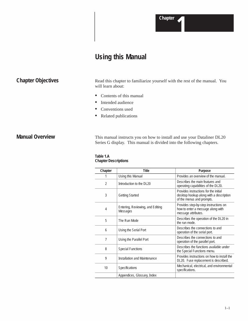
This manual instructs you on how to install and use your Dataliner DL20Series G display. This manual is divided into the following chapters.
Table 1.AChapter Descriptions
Chapter Title Purpose
1 Using this Manual Provides an overview of the manual.
2 Introduction to the DL20 Describes the main features andoperating capabilities of the DL20.
3 Getting StartedProvides instructions for the initialdesktop hookup along with a descriptionof the menus and prompts.
4 Entering, Reviewing, and EditingMessages
Provides step-by-step instructions onhow to enter a message along withmessage attributes.
5 The Run Mode Describes the operation of the DL20 inthe run mode.
6 Using the Serial Port Describes the connections to andoperation of the serial port.
7 Using the Parallel Port Describes the connections to andoperation of the parallel port.
8 Special Functions Describes the functions available underthe Special Functions menu.
9 Installation and Maintenance Provides instructions on how to install theDL20. Fuse replacement is described.
10 Specifications Mechanical, electrical, and environmentalspecifications.
Appendices, Glossary, Index
Chapter Objectives
Manual Overview
Chapter 1Using this Manual
1–2
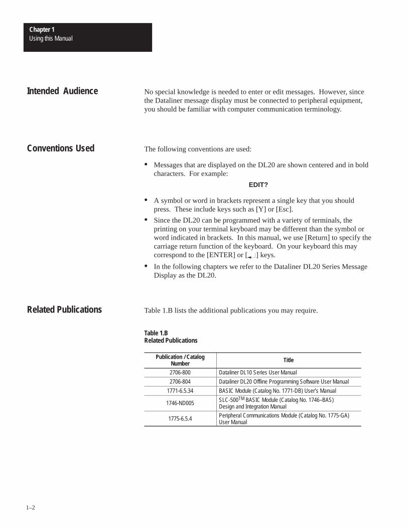
No special knowledge is needed to enter or edit messages. However, sincethe Dataliner message display must be connected to peripheral equipment,you should be familiar with computer communication terminology.
The following conventions are used:
• Messages that are displayed on the DL20 are shown centered and in boldcharacters. For example:
EDIT?
• A symbol or word in brackets represent a single key that you shouldpress. These include keys such as [Y] or [Esc].
• Since the DL20 can be programmed with a variety of terminals, theprinting on your terminal keyboard may be different than the symbol orword indicated in brackets. In this manual, we use [Return] to specify thecarriage return function of the keyboard. On your keyboard this maycorrespond to the [ENTER] or [ ] keys.
• In the following chapters we refer to the Dataliner DL20 Series MessageDisplay as the DL20.
Table 1.B lists the additional publications you may require.
Table 1.BRelated Publications
Publication / CatalogNumber Title
2706-800 Dataliner DL10 Series User Manual
2706-804 Dataliner DL20 Offline Programming Software User Manual
1771-6.5.34 BASIC Module (Catalog No. 1771-DB) User’s Manual
1746-ND005 SLC-500TM BASIC Module (Catalog No. 1746–BAS) Design and Integration Manual
1775-6.5.4 Peripheral Communications Module (Catalog No. 1775-GA)User Manual
Intended Audience
Conventions Used
Related Publications

A–B 2Chapter
2–1
Introduction to the DL20
This chapter describes some of the key features and operating capabilities ofthe DL20. For more detailed information, refer to the section of the manualthat describes the use of the feature or operating capability.
Dataliner DL20 Message Displays can store up to 1022 messages of varyinglengths and are available in three versions:
• 1 line by 20 characters
• 2 lines by 20 characters
• 4 lines by 20 characters
The operation of the 1, 2, and 4 line displays are similar. Exceptions arenoted in this manual.
The 20 character alphanumeric Vacuum Fluorescent Display (VFD) can beread from a distance of:
• 30 feet (9.1 meters) on the 1 line display
• 25 feet (7.6 meters) on the 2 and 4 line displays
The DL20 can display:
• Uppercase and lowercase letters
• Punctuation marks
• Special symbols (see Appendix A)
You program messages using:
• Keyboards (Catalog No. 2706-NK1 or -NK2)
• RS-232 terminal
• Allen-Bradley Industrial Terminals
• DEC VT series terminals
Messages are stored in DL20 memory which is maintained by a lithiumbattery-backed power supply. The lithium battery is part of the internalcircuitry, no additional batteries are required. An EPROM for nonvolatilemessage storage can override the message RAM (on 16K or 8K units).
Chapter Objectives
Overview of DL20

Chapter 2Introduction to the DL20
2–2
Message Editing Software
You configure and enter messages into the DL20 by attaching an optionalkeyboard, RS-232 CRT, or dumb terminal. The DL20 display prompts youwith easy to follow questions and instructions simplifying setup andconfiguration. Using a terminal or printer, you can list operating parameterssuch as baud rate or parity.
A DL20 time and date clock lets you display and/or print the time and datewith a message.
A debug mode verifies the operation of the host controller program. You can also perform self test functions.
Optional Offline Programming Software
DL20 Offline Programming Software (Catalog No. 2706-NP3) for IBM orcompatible computers lets you create, edit, and store messages on a personalcomputer. You can then download messages to the DL20 using acommunications cable.
Storing Messages
You can store DL20 messages on:
• Tape using an Allen-Bradley Data Recorder (Catalog No.1770-SA, -SB)or EPI STR-LINK II, III Data Recorder.
• Disk when using the DL20 Offline Programming Software.
All tape and computer operations (writing, reading, write verify, and readverify) are automatic with easy to follow prompting from the DL20.
Chapter 2Introduction to the DL20
2–3
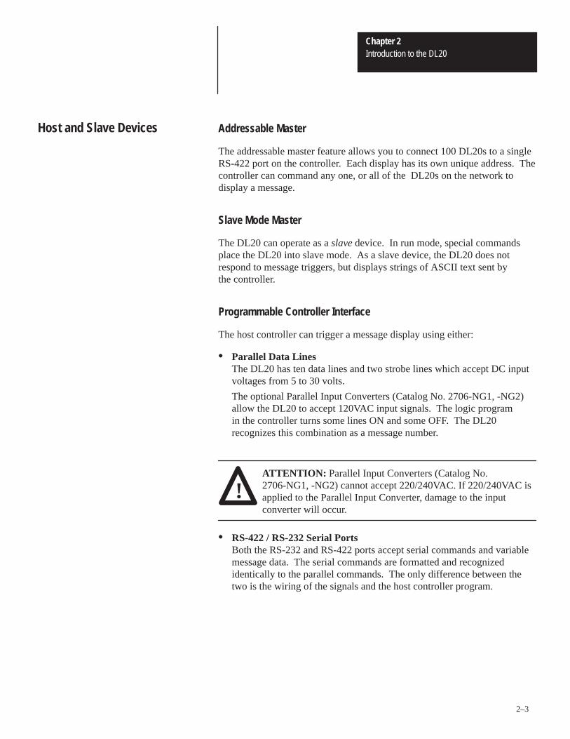
Addressable Master
The addressable master feature allows you to connect 100 DL20s to a singleRS-422 port on the controller. Each display has its own unique address. Thecontroller can command any one, or all of the DL20s on the network todisplay a message.
Slave Mode Master
The DL20 can operate as a slave device. In run mode, special commandsplace the DL20 into slave mode. As a slave device, the DL20 does notrespond to message triggers, but displays strings of ASCII text sent by the controller.
Programmable Controller Interface
The host controller can trigger a message display using either:
• Parallel Data Lines The DL20 has ten data lines and two strobe lines which accept DC inputvoltages from 5 to 30 volts.
The optional Parallel Input Converters (Catalog No. 2706-NG1, -NG2) allow the DL20 to accept 120VAC input signals. The logic program in the controller turns some lines ON and some OFF. The DL20 recognizes this combination as a message number.
!ATTENTION: Parallel Input Converters (Catalog No.2706-NG1, -NG2) cannot accept 220/240VAC. If 220/240VAC isapplied to the Parallel Input Converter, damage to the inputconverter will occur.
• RS-422 / RS-232 Serial PortsBoth the RS-232 and RS-422 ports accept serial commands and variablemessage data. The serial commands are formatted and recognizedidentically to the parallel commands. The only difference between thetwo is the wiring of the signals and the host controller program.
Host and Slave Devices

Chapter 2Introduction to the DL20
2–4
Auxiliary Devices
Messages that display on the DL20 can be sent to a printer with the time and date.
On large machines, or on production lines, you may want to use a remotedisplay. The DL20 can connect to 100 slave DL10 displays (up to 4000feet away). Each DL10 can have a different address. You can define, on amessage-by-message basis, the slave display on which a triggered messageappears. Triggered messages can be sent to individual or all slaves.
Power On Testing
When power is first applied to the DL20, a series of test programs are run.They check the circuitry in the display and the integrity of messages stored inmemory. You can run these test programs from the programming keyboardor a controller program.
Autorun
The autorun feature allows the display to restart in run mode on powerup ifthe display was turned off in run mode. A message displays for threeseconds indicating that the DL20 is entering the autorun mode. An autorunmessage, if present, is the first message displayed.
Note: All diagnostics must pass before the DL20 restarts in run mode. Inaddition, the user memory must not have been lost while the power was off.
CPU ACTIVE Light
The CPU ACTIVE light on the front panel must receive a periodic signalfrom the CPU to illuminate. Its normal appearance ranges from periodicflashing to steady illumination.
Self Testing and Diagnostics

Chapter 2Introduction to the DL20
2–5
Background MessageThe background message is a user-defined message that automaticallydisplays when no other messages are being displayed.
Invisible MessageInvisible messages do not appear on the display when triggered, nor do theyaffect what is on the display. Invisible messages can be sent to slaves,printed, or saved in the Historical Event Stack.
Special MessagesSixteen preprogrammed messages are available to trigger specific functions.They can clear the display, reset the DL20, test batteries, print HistoricalEvent Stack, clear the Historical Event Stack, halt run mode and start runmode. Special messages are optional and can simplify programmingrequirements.
Formatted Variables with Decimal PointYou can imbed a formatted variable with a decimal point in a message.When programming a message variable, you can specify:
• number of spaces the variable will occupy
• where to place the decimal point
• whether leading zeros should appear or be replaced by blanks
Data Trigger ModesSeparate data modes are available for inputting message triggers andvariables through the parallel port. Message triggers can be binary, whilevariable data can be BCD, or vice versa.
Dynamic Message ChainingDynamic chaining allows you to load 20 message triggers into the DL20causing those messages to display over and over again.
Historical Event RecordingHistorical Event Recording allows the DL20 to remember messages thatwere displayed. These messages can then be printed all at once or at a latertime. See Chapters 4 and 5 for details on Historical Event Recording.
Baud Rate
The DL20 supports baud rates of 300, 1200, 9600. On powerup, the DL20displays the baud rate currently in effect.
ParityThe DL20 can transmit data with odd, even or no parity. Data received bythe DL20 is not checked for parity. The parity you select is displayedimmediately after the baud rate on powerup.
Message Options
Communications Options

Chapter 2Introduction to the DL20
2–6
Table 2.A lists the optional accessories.
Table 2.AAccessories
Item Description Catalog No.
DL20 CableConnects Allen-Bradley Industrial Terminals T1 throughT4 or most DTE type dumb terminals.(Male 25 pin D-shell)
2706-NC1
DL20 Cable
Connects Allen-Bradley Terminals 1784-T45, -T47, -T50,-T60, other IBM compatibles or DEC VT52, VT100, orVT101 Terminals. (Female 25-pin D-shell)
Use 25 to 9-Pin AT Adapter with this cable for 1784-T50or -T60 Industrial or IBM AT computers.
2706-NC2
Data RecorderCable Connects EPI STR-LINK II or III Data Recorders to DL20. 2706-NC3
Data RecorderCable
Connects Allen-Bradley 1770-SB or -SA Data Recorders to DL20.
2706-NC4
A-B TerminalCable
Connects A-B Terminals to EPI STR-LINK II or III DataRecorders. Cable is required if an Allen-BradleyIndustrial Terminal and EPI STR-LINK II or III DataRecorder is used. Cable is not needed if programmingkeyboards (Catalog No. 2706-NK1 or -NK2) are used.
2706-NC5
DL20Development
Software
Off-line Programming Software for IBM or compatiblecomputers with 5.25 inch or 3.5 inch disk drive.
2706-NP3
Keyboard Full travel keyboard 2706-NK1
Keyboard Membrane keyboard 2706-NK2
Addressing BarAllows DIP switch selection of an address when multipleDL20s are on an RS-422 network. If Addressing Bar isnot used, address is selected during programming.
2706-NF1
120V ParallelInput Converter
Connects to the DL20 parallel input port and allowsmessages to be triggered using 120 VAC inputs.
Display Mounted ConverterPanel Mounted Converter
2706-NG12706-NG2
Enclosure
NEMA Type 12/13 enclosure with mounting holes andcutout for DL20. Access door has gasket.
One or Two Line DisplaysFour Line Displays
2706-NE12706-NE2
Flush Mounting Kits
Eliminates the standard bezel supplied with the display.
One or Two Line DisplaysFour Line Displays
2706-NJ12706-NJ2
Accessories

A–B 3Chapter
3–1
Getting Started
This chapter describes how to connect and powerup the DL20 for desktopmessage programming.
To set up the DL20 for desktop use, you need:
• Three-prong AC line cord
• Keyboard ( Catalog No. 2706-NK1 or -NK2)The keyboard connects to the DL20 via a cable attached to the keyboard
Cables are available to connect the DL20 with Allen-Bradley IndustrialTerminals T1 through T4, most DTE type dumb terminals, DEC VT52,VT100, VT101 Terminals and IBM compatible computers. See Table 2.A,Accessories.
Connect Power Cord
E. GND
AC PWR
120 VACHOT NEU
26 27 28BLACKWHITE
GREEN
Attach the power cord. One end of the cord has a three-prong plug, the otherend has three colored spade connectors: white, green, and black.
• Connect the black lead to terminal 26, the 120V AC HOT terminal onthe rear of the DL20
• Connect the white lead to terminal 27, the NEU terminal
• Connect the green lead to terminal 28, the E. GND terminal.
!ATTENTION: The ground wire is ESSENTIAL for properoperation. Without this lead, the chassis does not protect the in-ternal circuitry from static electricity or electrical noise; nor willit protect you from shock if there is an electrical short to the case.
Chapter Objectives
Desktop Hookup

Chapter 3Getting Started
3–2
Connect Programmer
To create messages, you need to connect a keyboard or attach aprogramming terminal.
RS422
+
RS 232OUT
RS 232 IN GND
+12VDCOUT
SERIAL COMM PORT
RS422
–
4 5 6 7 8 9
Cable - See Table 2.AKeyboard
Catalog No. 2706-NK1, -NK2
ProgrammingTerminal
Programming TerminalsThe programming cable hooks up similarly. One end of your cable has a Dtype connector which mates to a D connector on your terminal. Connect thisend of the cable to the serial communication port on your computer. On theAllen-Bradley terminals, use the Port B connector.
The other end of your cable has three numbered spade connectors whichattach to the similarly numbered terminals on the back of the DL20.
KeyboardThe telephone type connector on the keyboard cable plugs into the KY BDconnector on the back of the DL20. Only use the KY BD connector withprogramming keyboards (Catalog No. 2706-NK1 or -NK2).
!ATTENTION: Do not connect or disconnect the keyboardswhen power is applied to the DL20. Damage to the DL20 couldresult. Do not connect or disconnect a peripheral device to theserial RS-232/RS-422 ports of the DL20 when the display is inrun mode. Erroneous data could be entered.

Chapter 3Getting Started
3–3
When power is applied, the DL20 automatically enters a self test mode anddisplays the firmware revision number of the DL20 and the number of lines.
TESTING UNIT 3.00 2L
If the BATTERY LOW message is displayed, return the DL20 for batteryreplacement. The battery is not user-serviceable.
BATTERY OK
All display segments light up briefly.
SELF TEST OK
Note: If PRESS 9 @ 9600 BAUD is displayed, press the number [9] and theDL20 will continue normally.
The following message appears after the diagnostic tests have passedshowing the size of the user memory (8K, 16K, or 31K).
RAM SIZE; 31K
The baud rate then appears: 300, 1200, or 9600. The baud rate of theprogramming terminal or keyboard must match this baud rate.
BAUD = XXXX
Appendix E describes how to configure baud rate of the keyboards (CatalogNo. 2706-NK1 or -NK2).
Note: After the baud rate (or other switch selectable setting) is changed onmany programming terminals, you must cycle the power before the changestake effect.
The parity setting (odd, even, or none) of the DL20 appears. Characters arealways sent from the DL20 with the indicated parity. Characters of anyparity are received by the DL20, regardless of the parity setting.
NO PARITY
Initial Startup

Chapter 3Getting Started
3–4
The master address of the DL20 then appears. A 0 indicates that a masteraddress was not selected. Chapter 8 tells how to select a master address.
MASTER ADDRESS: 0
Finally, this prompt appears (unless the DL20 was powered down in therun mode.):
EDIT?
If the DL20 was powered down in the run mode, this prompt appears:
AUTORUN
possibly followed by other messages.
To return to edit mode, press [Esc] on your terminal three times. The EDIT?prompt will appear.
You are now ready to create messages.
When programming the DL20, you are prompted to enter specific types ofinformation. The DL20 uses two types of prompts, Yes/No prompts andnumeric prompts. Each type requires a specific type of response.
Yes/No Prompts
Yes/No prompts require that you type [Y] for Yes or [N] for No. Only theletters Y or N (upper or lowercase) are accepted as responses. An exampleYes/No prompt is:
EDIT?
Press [Return] after typing [Y] or [N] to accept the response. For example:
EDIT? [Y]
Some Yes/No prompts have a default response that displays. For example:
PRINT MSGS? N
To accept the default, just press [Return]. To change the response, enter [Y]and [Return].
Types of Prompts
Chapter 3Getting Started
3–5
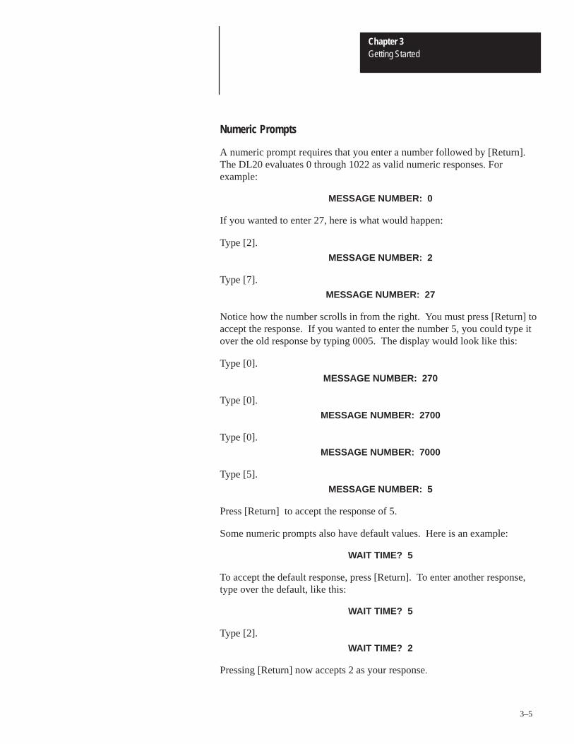
Numeric Prompts
A numeric prompt requires that you enter a number followed by [Return].The DL20 evaluates 0 through 1022 as valid numeric responses. Forexample:
MESSAGE NUMBER: 0
If you wanted to enter 27, here is what would happen:
Type [2].
MESSAGE NUMBER: 2
Type [7].
MESSAGE NUMBER: 27
Notice how the number scrolls in from the right. You must press [Return] toaccept the response. If you wanted to enter the number 5, you could type itover the old response by typing 0005. The display would look like this:
Type [0].
MESSAGE NUMBER: 270
Type [0].
MESSAGE NUMBER: 2700
Type [0].
MESSAGE NUMBER: 7000
Type [5].
MESSAGE NUMBER: 5
Press [Return] to accept the response of 5.
Some numeric prompts also have default values. Here is an example:
WAIT TIME? 5
To accept the default response, press [Return]. To enter another response,type over the default, like this:
WAIT TIME? 5
Type [2].
WAIT TIME? 2
Pressing [Return] now accepts 2 as your response.

Chapter 3Getting Started
3–6
Figure 3.1 shows the main menu flowchart.
Figure 3.1Menu Flowchart
NBack to EDIT? PromptEDIT?
Powerup
RUN? SPECIAL FUNCTIONS?
Back to EDIT? Prompt
Edit Mode Details in Chapter 4
Run Mode Details in Chapter 5
[Esc] [Esc] [Esc]
Special Functions Details in Chapter 8
N N
Y Y Y
Three selections are available from the main menu (edit mode, run mode, andspecial functions). The first entry in the main menu is:
EDIT?
Edit mode lets you enter new messages or modify old ones. Chapter 4 describes edit mode in detail. For now, if you type [N] and[Return] the next main menu prompt appears:
RUN?
Run mode is used most of the time. In run mode, the DL20 acceptscommands and data from the programmable controller or control system.Chapter 5 describes run mode. To exit run mode, press [Esc] three times.Type [N] [Return] to get the next main menu prompt:
SPECIAL FUNCTIONS?
Special functions are support tools for programming. Special functions areaccessed via menu control like all functions in the DL20. Chapter 8describes the special functions.
The various special functions fall into nine categories. Some categories, likedebug mode, simply execute the special function selected. Other categories,like tape operations, have submenus.
Most functions return to the main menu when done. However, you canreturn to the main menu at any time by pressing [Esc] three times. You cando this in any mode without losing message data. You can also abort manyspecial functions, such as print messages or tape operations, by pressing[Esc] three times.
Main Menu
Returning to Main Menu

A–B 4Chapter
4–1
Creating and Editing Messages
This chapter describes how to create, edit, and save messages.
The DL20 can store up to 1022 messages of varying lengths. Each messageconsists of:
• message number (1 - 1022)
• message text
• message attributes (control how message displays)
The process of entering and changing messages in the DL20 is calledmessage editing. You can add or delete characters or words at any point in amessage. If the display is in run mode, you need to press [Esc] three times toexit run mode and display the EDIT? prompt. To enter edit mode, simplypress [Y] [Return] at the EDIT? prompt. See Figure 4.1.
EDIT? Y
You will be prompted for a message number:
MESSAGE NUMBER: 0
Enter the message number you want to edit. Most message numbers between1 and 1022 are valid. Message numbers 255, 256, 511, 512, 767, and 768 areinvalid message numbers.
Note: Messages 1 thru 16 are pre-programmed special messages which youmay want to use. Refer to Chapter 5 for details.
The editor tries to find the selected message. If the message is located, aportion of it is displayed. You can make changes to an existing message atany time. Editing an existing message is described later in this chapter.However, if the message is not located, a new message is created. Beforeyou can enter the message you must specify its attributes.
Many times when entering new messages into the DL20 you may not be surewhich message numbers are used. The default value for the message numberprompt will always be the last message edited. Press [Return] to select thedefault. Typing a [?] now causes the DL20 to search and find the next higherunused message number. Pressing [Return] again selects that messagenumber for editing.
Chapter Objectives
Entering the Editor

Chapter 4Creating and Editing Messages
4–2
Figure 4.1Edit Mode Menu for 2 Line DL20
N
Y or N
FLASH MSG?
Y or N
YNY
Y (N selects Line mode)
Y YY
PRINT MSGS?N Y
ALL LINES?N
LINE 1 ONLY? LINE 2 ONLY? USE LEAST USED?
Y
Y
Y
Y or N
Y or N
Y or N
Flashing cursor appears and new message can be entered
Y
If no messageexists
Shows portion of existingmessage.
To edit or change themessage, use Edit
Commands shown in Table 4.A.
MESSAGE NUMBER:
(Enter Number)
N N
EDIT?
SCROLL?
WAIT TIME?
(Enter Time)
AUTO CLEAR?
OUT TO SLAVE? TO ALL SLAVES?N
SLAVE NUMBER: 0
AUTO REPEAT?N
CHAIN MSG? NO INFINITE CHAINS MESSAGE NUMBER:0
N
TURN RELAY ON?
STACK MSG?
INVISIBLE MSG?
ENTER MSG
Displayed For 3 Seconds
① Note: Line mode prompts are different for 1 and 4 Line DL20s.
①
(Enter Number)
① ① ①

Chapter 4Creating and Editing Messages
4–3
Message attributes are properties that an individual message may have. Youare prompted for each attribute, one at a time. Some attributes are mutuallyexclusive-you can select either one, but not both.
Line Selection
If using a two or four line display, you must first specify the line or lines onwhich the message is to appear. The choices for the two line display are:
ALL LINES?LINE 1 ONLY?LINE 2 ONLY? USE LEAST USED?
On the four line display, you have six choices:
ALL LINES? LINE 1 ONLY?LINE 2 ONLY?LINE 3 ONLY?LINE 4 ONLY?USE LEAST USED?
The prompts for the two line display appear like this:
ALL LINES? N
If you select all lines, the message is displayed automatically as a line modemessage. The first line of the message appears on line 1, the second lineappears on line 2. If the message is longer than two lines, two new lines ofthe message appear on lines 1 and 2 after the wait time has elapsed. Amulti-line message can only be displayed in line mode.
LINE 1 ONLY? N
If you select line 1 only, the message is displayed on line 1 only. The message (if any) on line 2 is left intact.
LINE 2 ONLY? N
If you select line 2 only, the message is displayed on line 2 only. Again, themessage on line 1 is left intact.
USE LEAST USED? N
If you use the least-recently-used line, the message overwrites the oldest lineof information. The other line or lines are left intact.
Specifying Message Attributes
Chapter 4Creating and Editing Messages
4–4
Line-Scroll Mode
If you do not select ALL LINES, but choose to have a message displayed onone line only, you will be asked to select line or scroll mode:
SCROLL? N
At this point, you must decide whether the message is to be a line modemessage or a scroll mode message.
Scroll ModeSelect scroll mode to scroll a message across the display one character at atime. Characters enter from the right of the display and exit on the left. Line ModeLine mode displays messages one line at a time. Messages are broken intolines of 20 characters or less and displayed one line at a time. The lines areautomatically centered in the display. For example, the message “This is aline mode display.” would be displayed like this:
This is a line mode
display.
Remember, messages displayed on all lines of a two or four line display canbe line mode messages only, and you will not be prompted for SCROLL?
Printing Messages
The next attribute prompt allows you to send the message to the printer whenit is triggered:
PRINT MSG? N
If you answer Yes, this message prints every time it is triggered. Anyvariables within the message along with the date and time are also printed.
Specifying Message Attributes

Chapter 4Creating and Editing Messages
4–5
Slave Messages
If you answer No to the print messages prompt, you are asked if you want tosend messages to slave displays when triggered. It is possible to connect oneor more DL10 slave displays to the DL20. Messages displayed on the DL20can be sent to the slaves. In addition, a message can display on a particularslave display. Since there is only one serial port, a message cannot be bothprinted and sent to a slave. The DL20 displays the following prompt only ifyou have selected not to print the message:
OUT TO SLAVE? N
If you answer Yes, the message is routed to slave displays every time it istriggered. The DL20 prompts you with the message:
TO ALL SLAVES? Y
If you answer Yes to this prompt, the message you are editing is displayed onall connected slave devices, regardless of their addresses. You are thenprompted for the next attribute, message wait time. If you answer No to theabove prompt, this prompt appears:
SLAVE NUMBER: 0
Enter a number from 1 through 127. For example, if you enter the number30, all connected slaves that have 30 as their address will display thismessage when triggered. The following slave addresses are reserved andcannot be used: 0, 4, 6, 13, 18, 20, 22, 43, 45, 48-57. Address 127 displaysall messages sent to any slave number. Chapter 9 describes how to connectslave displays.
Message Wait Time
The next message attribute controls how long the message is displayed. Wait time range is 0-31.
WAIT TIME? 5
For a scroll mode message, the wait time is the amount of time that passesbefore the next character is scrolls the display. The units of time are Tenthsof a Second.
For a line mode message, the wait time is the amount of time that passesbefore the next line shows in the display. The units of time are Seconds.

Chapter 4Creating and Editing Messages
4–6
Auto Clear
Auto clear controls whether the display clears after a message displays:
AUTO CLEAR? N
If you answer Yes, the DL20 clears the display after the message has beendisplayed for the specified wait time. If you answer No, the last line or linesof the message are displayed until replaced by another message.
Auto Repeat
Auto repeat allows a message to display repeatedly for an indefinite period oftime.
AUTO REPEAT? N
A message set to AUTO REPEAT continually retriggers itself aftercompleting its display. Auto repeat is inhibited if there are any pendingmessage triggers in the message queue. The queue will be explained later.Auto repeat terminates if another message is triggered. If an auto repeatmessage was called by another message in a message chain, the callingmessage repeats, followed by the auto repeat message.
Note: Do not use auto repeat for messages with variables or in a backgroundmessage.
Specifying Message Attributes

Chapter 4Creating and Editing Messages
4–7
Chaining Messages
The chain attribute allows a series of messages to display by triggering onlyone message. A message which automatically repeats itself cannot bechained to another message. If you answer Yes to auto repeat, the chainmessage prompt will not appear. The chain message prompt looks like this:
CHAIN MSG? N
If you answer Yes, a warning message appears:
NO INFINITE CHAINS
Note: A message should not be chained to itself, or a loop of chainedmessages should not be defined. Message loops such as these are notallowed. They can only be terminated by special messages #2 or #3,described in Chapter 5.
You are then prompted to enter a message number.
MESSAGE NUMBER: 0
Enter a number (1-254), then press [Return]. Now, whenever this message istriggered in the run mode, it is displayed normally. Then the messagechained to this one is displayed, regardless of whether messages are waitingin the message queue. The message queue is described in Chapter 5. Chainsof up to 35 messages can be created. Only message numbers 1 through 254are accepted.

Chapter 4Creating and Editing Messages
4–8
Here are some examples of AUTO REPEAT and CHAIN MSG attributes. Inthese examples, there are six messages:
Message 1: chained to 2
Message 2: chained to 4
Message 3: chained to 4
Message 4: neither chain nor auto repeat selected
Message 5: chained to 6
Message 6: auto repeat
Triggering a message causes it to be displayed. To illustrate the operation ofan auto repeat message, we will trigger message number 6. Message 6 isdisplayed, then redisplayed. Message 6 continues to be redisplayed untilanother message is triggered. If message 5 is triggered, it is displayed,followed by message number 6. Since message number 6 is an auto repeatmessage, message 5, then message 6 repeats until another message istriggered.
Here are some more examples. Triggering message 2 will cause message 2,then message 4 to be displayed. Triggering message 3 will cause message 3,then message 4 to be displayed. Triggering message 1 will cause message 1,then message 2, then message 4 to be displayed. Triggering message 4 onlycauses message 4 to be displayed. Since message 4 is not an auto repeatmessage, none of these triggering sequences is repeated.
Message chains up to 35 messages long can be automatically repeated. Thisfeature can be useful when using the DL20 as an informational display.
Note: Do not use messages with variables when using the chain messagesattribute.
Specifying Message Attributes

Chapter 4Creating and Editing Messages
4–9
Flashing Messages
The next attribute prompt is self explanatory:
FLASH MSG? N
Answering Yes to this prompt causes the message to flash once per secondwhen the message is triggered.
Relay Operation
!ATTENTION: Use relay for annunciator purposes only. Do notuse it for control.
The DL20 has a single-throw, double-pole internal relay. This relay can beenergized by messages. The relay attribute prompt looks like this:
TURN RELAY ON? N
If you answer Yes to this prompt, the relay is energized when the message istriggered, and de-energized when the message has terminated its display.
Important: The relay does not stay energized between message displays;triggering two messages with this attribute selected does not guarantee thatthe relay will remain energized continuously between the two messages.Similarly, an auto repeat message does not guarantee a continuouslyenergized relay.
The relay can also be energized by the battery low detector circuit within theDL20. This option is described in Chapter 8. If the relay is used to flag alow battery, it cannot be controlled by message attributes.

Chapter 4Creating and Editing Messages
4–10
Historical Event Recording
The Historical Event Recording prompt determines whether to place amessage in the Historical Event Recording Stack for later printing.
STACK MSG? N
If you answer Yes, every time the message is triggered, it is displayed andsent to a printer or slave as determined by the other message attributes. It isalso placed in the Historical Event Recording Stack to be printed out later.Any variables or the time and date within the message are also saved. Referto Chapter 5 for more information on the function of Historical EventRecording.
Invisible Messages
Invisible messages do not appear on the display when triggered, nor do theyaffect what is displayed. All other message features remain in effect. Themessage can still be sent to slaves, printed or saved in the Historical EventRecording Stack. To use invisible messages, enter Yes to this prompt:
INVISIBLE MSG?
This feature is useful if you only want a certain message to be displayed on aslave, printed, or put into the Historical Event Recording Stack.
All attributes have default values. The first time you enter a message into anew DL20, or one which has had its memory cleared, the defaults are shown.From then on, the defaults used when entering a new message are those lastselected. This feature allows you to quickly enter a number of messages thathave the same or similar attributes. To accept attributes as default, holddown the [ENTER] key until prompted for the message.
Specifying Message Attributes
Attribute Defaults

Chapter 4Creating and Editing Messages
4–11
After you have specified all the attributes, the DL20 displays:
ENTER MSG
for a few seconds. This alerts you to the fact that you are ready to enter themessage. Enter messages at the cursor position. The cursor initially appearsas a reverse space (all dots lit up). Most edit commands either affect thecharacter at the cursor position (which is called the cursor character), or theymove the cursor to different characters within the message. The cursor isalways at the center of the display. Edit long messages by moving the cursorto see various portions of the message using edit commands.
Table 4.A lists the edit commands.
Table 4.AEdit Commands
FunctionKeys Pressed
(Simultaneously)
Forward One Space Ctrl [L]
Back One Space Ctrl [H]
Up a Line(Move 20 characters to left within message)
Ctrl [K]
Down a Line(Move 20 characters to right within message)
Ctrl [J]
Delete a Character Ctrl [D]
Change or Review Message Attributes Ctrl [A]
Run Message Ctrl [R]
Erase Message Ctrl [E]
Toggle Uppercase Lock Ctrl [U]
Show Free Memory Ctrl [F]
Imbed Non-Decimal Point Variable Ctrl [V]
Imbed Formatted Decimal Point Variable Ctrl [X]
Change Variable Format Ctrl [C]
Imbed Time and Date Ctrl [T]
Show Edit Commands Ctrl [S]
Quit Edit Ctrl [Q]
These commands are described in the following paragraphs. Then we willgo through an example edit session.
To enter an edit command, hold down the control key (CTRL on someterminals), press the letter of the command, then release the control key. Ifyou are using the Allen-Bradley Industrial Terminal, the control key shouldbe pressed and released followed by the letter of the command.
Editing Messages
Edit Commands

Chapter 4Creating and Editing Messages
4–12
Move Cursor Forward One Space (Ctrl L)
Move the cursor forward one character position by typing control L. If thecursor is positioned at the last character in the message, the command isignored. Many terminals, other than the keyboards (Catalog No. 2706-NK1,-NK2), have a key with a forward arrow (→) marked on them. This key maymove the cursor forward (depending upon terminal type).
Move Cursor Backward One Space (Ctrl H)
Move the cursor backward one character position by typing control H.It moves the cursor one space back in the message. If the cursor is already atthe first character in the message, the command is ignored. Many terminalshave a key with a back arrow (←). Others have a key labeled backspace.Still others have both. These keys may move the cursor backward(depending upon terminal type).
Move Cursor Up One Line (Ctrl K)
The up-one-line command (control K) moves an entire display line (20characters) backward in a message. The command is ignored if the cursor isalready at the first line. Most terminals, other than the keyboards (CatalogNo. 2706-NK1, -NK2), have an up arrow key (↑ ) which generates thiscommand. This key may move the cursor up one line (depending uponterminal type).
Move Cursor Down One Line (Ctrl J)
The down-one-line command (control J) moves an entire display line (20characters) forward in a message. The command is ignored if the cursor isalready at the last line. Most terminals, other than the keyboards (CatalogNo. 2706-NK1, -NK2), have a down arrow key (↓ ) which generates thiscommand. This key may move the cursor down one line (depending uponterminal type).
Moving the Cursor

Chapter 4Creating and Editing Messages
4–13
The delete character command (control D) removes the character at thecursor position from the message. The cursor then moves to the nextcharacter. If the character deleted was the last character in the message, thecursor moves to the new last character. You can delete an entire messageusing the delete command. However, the message remains in memory andexists as a message with no characters; a null message.
Use the erase message command (control E) to delete an entire message.Before the message is erased, the following is displayed:
SURE? N
Press [Return] to ignore the command. Editing resumes where you left off.If you answer yes to the prompt, the message is erased from memory, and theeditor is exited. You will see the following prompts:
MSG DELETED
and then:
EDIT?
Deleting a Character (Ctrl D)
Erasing a Message (Ctrl E)

Chapter 4Creating and Editing Messages
4–14
You may need to change the attributes of a message that you are editing. Thenew message attributes command (control A), allows you to change themessage attributes without retyping the message. The command provides aseries of prompts just like you saw when you entered a new message.However, the defaults for the prompts now match the attributes currently ineffect for this message. You will also be given an opportunity to change themessage number. Type [Ctrl] [A]:
MESSAGE NUMBER: 7
The default for the prompt is the current message number. Type the newmessage number over the current number. Since no two messages can havethe same number, you must reassign a unique message number to themessage before pressing [Return]. If no new message number is desired, justpress return without changing the displayed message number. The DL20searches message memory for a message with the same number. If oneexists, you will see this prompt:
MSG EXISTS
followed by:
MESSAGE NUMBER: 7
You must try again. If the message number does not exist, the message underedit will be renumbered. The old message number then becomes free forre-assignment.
At this point, you will now be re-prompted for the message attributes, any ofwhich can be changed.
During editing, messages are displayed 20 characters at a time. As notedpreviously, you can move about the message, examining any part. When thissame message is displayed in Run mode, it is displayed much differently.The message may scroll, it may flash, or it may have variable data in it. Toquickly preview a message, type [Ctrl] [R], and the message is displayed justas it would in the run mode.
An auto repeat message will only run once, and a message with variable datawill have random data displayed. The run time simulation is as real aspossible, attached slaves and printers will work as they should and messagechains will be displayed. After the message has been displayed, the windowwill be restored, with the cursor left where it was originally. When editingyour first message, use control A to try different attributes and then usecontrol R to display the message and see for yourself what the differentattributes do.
Setting New MessageAttributes (Ctrl A)
Previewing a Message (Ctrl R)
Chapter 4Creating and Editing Messages
4–15
Variable data from the programmable controller may be imbedded in amessage. Up to twenty valid variables (total) per message may be displayedor printed this way. To imbed a variable in a particular location, type controlV. The control V will be shown as an up arrow (↑ ). When the message istriggered, the first numerical variable in the data queue replaces the up arrow.Chapter 5 describes this queue, and how to put values in these locations.Variables can be in the range of -32,768 to +32,767.
This feature allows you to control the displayed format of variable datawithin a message.
Variables can be in the range of -32,768 to +32,767. Three format parameters can be varied:
• field width, that is the number of spaces that the variable will take up
• decimal place, where a decimal place should be imbedded
• whether leading spaces in the field should be padded with blanks or zeros
To imbed a formatted variable into a message, use the message editor andtype control X where you wish the formatted variable to appear in themessage. The control X will be shown as a down arrow (↓ ) within themessage. The following prompt is displayed:
FIELD WIDTH: 0
A field width of 1 through 7 is valid.
Note: If a negative number is displayed, the first character of the field is aminus sign. You have no control over where the minus sign is placed in thefield. The amount of space taken by the variable when it is displayed, or onthe printout sheet when it is printed, is always equal to the field width.
Imbedding Variable Data (Ctrl V)
Imbedding Formatted Variable with Decimal Point (Ctrl X)

Chapter 4Creating and Editing Messages
4–16
You are then prompted for the decimal place:
DECIMAL PLACE: 0
The valid settings range from 0 thru 6. If the decimal position is selected tobe zero, no decimal place will be shown in the field. The value entered forthe decimal position is always the location that the decimal place occupies.That is, entering 1 for decimal position places the decimal in the rightmostcharacter position, i. e. the last character of the field. Entering a 2 fordecimal puts it one to the left of the rightmost character. The value enteredfor the decimal position can never exceed the number entered for field width.That is, entering a field width of four means that you can only specify 0 thru4 for a decimal position.
The last prompt appears like this:
PAD WITH 0? N
This controls whether the unused spaces in the field are padded with zeros orspaces. For example, if you have a field width of 4, 0 as your decimal place,and the value being displayed is 2, it can be displayed one of two ways,either as 2 or as 0002.
Use the change variable command (control C) to change the format of aformatted variable. Position the cursor at the variable. A formatted variableis shown as being a down arrow (�), as opposed to a simple variable, whichis shown as an up arrow. When the cursor is positioned for the formattedvariable down arrow, type [Ctrl] [C]. You are again prompted for theformatting parameters. The defaults for these formatting parameters are thecurrent settings.
Note: Do not use the chain message or auto repeat attribute when imbeddingvariables.
Changing Variable Format (Ctrl C)

Chapter 4Creating and Editing Messages
4–17
Imbed the time and date in a message, by typing a [Ctrl] [T] at the location inthe message that you want the time displayed at. The control T is displayedas the character @. When the message is displayed, the time and datereplace the @ character. The time and date string has the following format: HH;MM;SS DDD MMM DT YEAR where:
HH = hour MM = minuteSS = secondDDD = day (MON,TUE, etc.)MMM is the month (JAN, FEB, etc.)DT = dateYEAR
The YEAR string is not displayed, but is printed on the printer if the messageis printed and if the printer has a carriage width of 26 characters or more.
If you want to see how much free memory is left for new messages, oradditions to the message under edit, type [Ctrl] [F]. You will see thisprompt:
FREE MEM = 16042
The example above means there are 16042 bytes left to be filled. Eachmessage reserves 14 bytes of memory, in addition to the memory used for theactual characters of the message. Blank spaces, control T’s (@) and controlV’s (↑ ) use one byte each.
Imbedding Time and Date (Ctrl T)
Showing Available Memory (Ctrl F)

Chapter 4Creating and Editing Messages
4–18
Some people prefer all uppercase type for all messages. Others prefer alluppercase type for just important messages. The optional keyboards(Catalog No. 2706-NK1, -NK2) have a shift-lock key. If you are usinganother type of terminal, type [Ctrl] [U], and this prompt is displayed:
UPCASE ONLY
After three seconds (or press any key) the prompt will go away. The editwindow is restored with the cursor where you left it last. Type any lowercase letter, and note that it is converted into uppercase, then inserted into themessage. Type [Ctrl] [U] again and this prompt is displayed:
LOWCASE OK
Once again, after three seconds the prompt will disappear. The uppercaselock/unlock setting is stored in memory and the setting will remain the same,even between edit sessions or when power is disconnected.
The show command displays a brief description of all the available editcommands. If you happen to forget a control code, type [Ctrl] [S] to list thecommands. Press [Esc] to stop the listing. Pressing any other key allows youto step through the listing more rapidly. After pressing [Esc], editingresumes where you left off.
Upper Case Lock-Unlock(Ctrl U)
Show Commands (Ctrl S)
Chapter 4Creating and Editing Messages
4–19
To exit the edit mode, type [Ctrl] [Q]. The edit session terminates, and themessage is saved. A notice is displayed and the EDIT? prompt reappears.
EDIT DONE
EDIT?
Press [Esc] three times to exit from the editor. The message under edit issaved, but a prompt is not displayed.
Let’s go through an example edit session. This should clarify the operationof the editor. Enter the editor by responding with a Yes to the edit prompt.You will then see the following prompt:
MESSAGE NUMBER: 0(or last edited message number)
Enter a number, for example [1][8] [Return].
Let us assume the message number does not exist. The next prompt,assuming you are using a one line display, is the scroll mode prompt:
SCROLL? N
The default in this case is line mode. Press [Return] to make message 18 aline mode message. The next prompt is the print message prompt:
PRINT MSG? N
The default this time is not to print the message. Just press [Return]. Thenext prompt will appear:
OUT TO SLAVE? N
We do not have slaves connected, so just press [Return].
WAIT TIME: 5
The wait time controls how fast different lines are displayed. This is a linemode message, so the wait time between lines of the message is five seconds.This seems OK, so just press [Return].
AUTO CLEAR? N
Exiting the Editor (Ctrl Q)
Entering anExample Message

Chapter 4Creating and Editing Messages
4–20
We will set this message up so that the display is cleared when the message isfinished. Type [Y].
AUTO CLEAR? Y
Now press [Return].
AUTO REPEAT? N
We do not want the message to continually repeat so just press [Return].
CHAIN MSG? N
We do not want to chain this message, so just press [Return].
FLASH MSG? N
We do not want the message to flash, so just press [Return].
TURN RELAY ON? N
We do not want to energize the relay so just press [Return]
STACK MSG? N
We do not want to stack the message in the Historical Event Stack so press[Return].
INVISIBLE MSG? N
We want this message to actually be displayed, so press [Return]. Thefollowing prompt then appears:
ENTER MSG
--
The last prompt appears for a few seconds indicating that a new message isbeing created, followed by a cursor. The cursor is a blinking solid block; it isshown as an underline in this manual. Enter a sample message.
ALLEN-BRADLEY
Here, the string ALLEN-BRADLEY was typed in. Note that the charactersscrolled off to the left, and the cursor is positioned at the last charactertyped. Type some more:
ALLEN-BRADLEY BULLETIN 2706 MESSAGE DISPLAYS

Chapter 4Creating and Editing Messages
4–21
Try moving the cursor. Forward one space (control L), backward one space(control H), up a line (control K), and down a line (control J). Type a fewbackspace characters (control H) and watch the cursor move back.
ALLEN-BRADLEY BULLETIN 2706 MESSAGE DI SPLAYS
Here we typed backspace six times. Now type up a line (control K).
ALLEN-BRADLEY BULL ETIN 2706 MESSAGE DISPLAYS
Change the words BULLETIN 2706 to DATALINER. First position thecursor to the B in BULLETIN. Type backspace (control H) three times:
ALLEN-BRADLEY B ULLETIN 2706 MESSAGE DISPLAYS
Now type delete (control D).
ALLEN-BRADLEY U LLETIN 2706 MESSAGE DISPLAYS
Notice that the character is eliminated and the remainder of the message tothe right of the cursor scrolls one position to the left. Type delete (control D) 12 more times:
ALLEN-BRADLEY MESSAGE DISPLAYS
Type the word DATALINER.
ALLEN-BRADLEY DATALINER MESSAGE DISPLAYS
Type quit (control Q) to exit the editor.
EDIT DONE
EDIT?
If we wanted to re-edit message 18, you would not have to reanswer theattribute prompts.
EDIT? Y
MESSAGE NUMBER: 18
ALLEN-BRADLEY DATALINER MESSAGE DISPLAYS
The cursor is positioned at the first character of the message. Editing mayproceed as before.

Chapter 4Creating and Editing Messages
4–22
The example below shows how to estimate memory usage. Every messageprogrammed has 14 bytes of overhead. Also, every space, control T, controlV, and control X also use one byte.
Example: DL20 contains 475 messages with an average length of 35characters.
31,000-23,275
7,725
Total Memory AvailableTotal MemoryUnused Memory
(475 x 14) + (475 x 35) = 23,275
Overhead + Message Text= Approximate Total
The Historical Events Stack uses a maximum of 3000 bytes of unusedmemory. If the Historical Event Stack is used in your application, enoughnon-message memory space should be allocated.
Estimating Memory Usage

A–B 5Chapter
5–1
Run Mode
This chapter describes how to trigger and display previously enteredmessages.
To place the DL20 in the run mode, answer Yes to the run mode prompt:
RUN? Y
The DL20 clears the display and enters the run mode.
The DL20 remains in the run mode indefinitely. If power fails, the DL20remembers that it was in the run mode. On powerup, it resumes the runmode, if it passes the powerup self diagnostics.
The messages:
TEMP MASTER ADD: (0)
or
MASTER ADDRESS:
and
AUTORUN
are displayed for three seconds before the DL20 enters the run mode. If anautorun message has been selected, it is now displayed. It takes about twentyseconds to run the powerup self test and during this time prior toAUTORUN, no messages may be triggered.
Chapter Objectives
Entering the Run Mode
Autorun Feature
Chapter 5Run Mode
5–2
A message can be specified as an autorun message. This message istriggered immediately after entering run mode. It is always the first messagein the queue, regardless of the state of the parallel port data lines. Use thisfeature as a method of displaying an initial message upon powerup.
An autorun message is also useful when using the DL20 for demonstrationsor as an information display. Any number of messages may be displayedautomatically on powerup by chaining the autorun message to them. Thesemessages are displayed on powerup, whether the DL20 is hooked up to acontroller or not. Remember, do not make a closed loop of chained messages(i.e., 1 chained to 2 chained to 3 chained to 1). If you want the chain torepeat continuously, make the last message in the chain an auto repeatmessage.
Chapter 8 describes how to set or disable the autorun message.
The background message is displayed when the message stack is empty. Usethe background message to display a fixed message when the DL20 is notshowing anything pertinent to the operation of the application. For example,you can have the DL20 show the time of day when no other messages aredisplayed. Use the Set Up Master special function (Chapter 8), to enter abackground message number.
To exit run mode, you must press [Esc] three times. The DL20 displays thefollowing prompt when the run mode is terminated:
EDIT?
Autorun Message
Background Message
Exiting the Run Mode

Chapter 5Run Mode
5–3
In run mode, the DL20 waits for commands from the host. These commandscan:
• Trigger a message display
• Contain variable display data
To get a better idea of how the DL20 works, you must understand theconcept of a queue. A queue is simply an ordered pile of data. Informationcan be put in or taken out of the queue. Information is always taken out inthe same order that it is put in, (i.e. first-in first-out). There are two queues:
• One queue holds message numbers
• The other queue holds variable data
The DL20 queues up data and message numbers. It empties the messagenumber queue as fast as it can. A message requires a certain amount of timeto display. An entry is pulled from the data queue each time a control V orcontrol X is found in a message. Control V or control X is imbedded in amessage in the edit mode. Control V or control X designates “display datavalue here”. Control V appears as ↑ (up arrow) when editing a message.Control X appears as ↓ (down arrow) when editing a message.
To better understand how the queues operate, refer to this example: Assume message 2, is “Boiler pressure is ↑ PSI, temperature is ↑ degrees”.This message is printed along with actual variable data from the host.
Loading Data Queue
First, you must load up the data queue with the variable data. Since the firstcontrol V (up arrow) is the pressure reading, this is the first data that shouldbe sent followed by the temperature. The data queue will look like this:
First entry: 775Second entry: 451
Loading Message Trigger Queue
Assume that the message queue is empty. To get the message to display, youmust load the message queue with the message number 2. When this is done,the message queue will look like this.
First entry: 2
The message is displayed immediately if there are no messages in the queue,or after any previously-triggered messages have been displayed.
Triggers and Queues
Loading and Unloading Queues

Chapter 5Run Mode
5–4
Unloading Queues
A queued message is displayed immediately if there are no messages in thequeue, or as soon as any previously-queued messages have been completelyexecuted. The message may also be shown on slave displays, or it may belisted on a printer. The message is evaluated up to the first control V.
Boiler pressure is
At this point, the variable queue still looks like this:
First entry: 775Second entry: 451
Now, the first entry is taken from the queue.
Boiler pressure is 775
The queue now looks like this:
First entry: 451
The message is then evaluated at the second variable.
Boiler pressure is 775 PSI, temperature is
Now, the second variable is unqueued, leaving both queues empty, and themessage is displayed.
Boiler pressure is 775 PSI; temperature is 451 degrees.
Both the data queue and the message queue have a capacity of twenty entries.The DL20 will ignore all entries when the queue is full. Because of this, theDL20 is limited to twenty variables embedded within any one storedmessage.
Queue Capacity

Chapter 5Run Mode
5–5
In this example, three messages are triggered in rapid succession. First, themessage 1 is triggered. The message queue looks like this:
First entry: 1
The entry is removed from the queue immediately. Message 1 is displayed.While it is being displayed, a command to trigger message 2 is queued. Themessage queue now looks like this:
First entry: 2
This entry is NOT removed, because message 1 is still being displayed andits wait time has not elapsed. Next, a command to trigger message 3 isreceived. The message queue now looks like this:
First entry: 2Second entry: 3
After a short time, message 1 completes its display period. The DL20,always working to empty the queue, removes the first entry from the queue, atrigger for message 2. The message queue looks like this:
First entry: 3
When message 2 completes its display, the trigger for message 3 is removed.The queue is now empty. The DL20s message 3 then waits indefinitely foranother message.
Display characteristics are determined by the attributes assigned to aparticular message. For example, if zero wait time is assigned to 3 messagestriggered in rapid succession, the first two messages are displayed tooquickly to be read. However, assigning a wait time to a message assures it isdisplayed for the selected period of time. Other messages triggered duringthis time are stacked in the queue.
The DL20 displays messages and data as a result of commands sent to itfrom a host. Commands may be entered in one of two ways:
• Parallel input consisting of twelve inputs (See Chapter 7)
• Serial input using RS-232 or RS-422 port (See Chapter 6)
Important: Both serial and parallel inputs to the display cannot be usedsimultaneously. One or the other must be used.
Queuing Examples
Transferring Data to be Queued

Chapter 5Run Mode
5–6
Message numbers 1-16 are special messages which provide a variety offunctions. Special messages are disabled by entering a regular message intheir place. Once a regular message is created, it must be erased to regain thefunction of the special message.
For example, if a user message is stored as message 3, triggering message 3no longer resets the DL20.
Note: Use Control E to erase a regular message.
Special Message #1: Clear Display
All lines of the DL20 are cleared when special message #1 is triggered. Alllines of any attached DL10 slave displays are also cleared.
Here is an example of using special message #1: fault messages need to bedisplayed and remain displayed until the fault is cleared and someacknowledgement is made by the machine operator. One way to do this is toprogram fault messages as auto repeat messages. When the fault message istriggered, it is displayed continuously. A fault cleared button on the machinetriggers special message #1 which clears the display. The display remainsclear until another message is sent.
Special Message #2: Clear Display and Queues
Special message #2 clears the display along with the message trigger andvariable data queues.
This message is useful when implementing priority messages. For example:you might want to display routine progress prompts and have three or fourmessages waiting to be displayed. Now let’s say a fault happens. The faultmessage is displayed after the other (presumably less urgent) messages aheadof it in the message queue are displayed.
Triggering special message #2 prior to a fault message interrupts whatevermessage is being displayed, cancels the display of any message triggers inthe queue and immediately displays the fault message. This allows the faultmessage to be displayed immediately, no matter what the DL20 was doingpreviously.
Special Messages

Chapter 5Run Mode
5–7
Special Message #3: Reset DL20
Special message #3 has the same effect as cycling power. This is useful ifyou want to run the powerup self test. This is sometimes useful for systemsthat have a system test function. If you send the DL20 special message #3when the test button is pressed, the display will go through its self tests.
Triggering special message #3:
• terminates the display of any message running
• clears message and data queues
• causes the autorun message to be displayed
Special message #3 exactly mimics the conditions that occur when the poweris removed and then restored.
Special Message #4: Test Battery
Special message #4 tests the battery. When special message #4 is triggered,the battery is tested and a message is shown, either BATTERY OK orBATTERY LOW. Although the battery is normally checked on powerup,some applications are running continually. Special message #4 provides away for your programmable controller to periodically test the battery. If therelay flags battery special function is selected, then the relay is energizedeach time special message #4 is triggered and the batteries are low.
Special Message #5: Print HE Stack
Special message #5 prints the contents of the Historical Event (HE) Stack,with the most recently stacked messages printed first. Messages are notremoved from the stack as they are printed. Messages are printed until theentire stack is printed, or until stack printing is halted by triggering specialmessage #6.
While the HE Stack is being printed, any message triggers or variable datathat are received are stored in the queue. If a message trigger is receivedwhile printing the HE Stack, it is displayed when you terminate printing orwhen the entire HE Stack is printed.
Chapter 5Run Mode
5–8
Special Message #6: Stop Printing HE Stack
Special message #6 stops the printing of the Historical Event (HE) Stack.Special message #6 terminates the printout, but whatever message iscurrently being printed prints out in its entirety. Normal message run moderesumes when printing ends.
Printing of the stack with special message #5, stopping printing with message#6 and restarting printing again with special message #5 causes the stack tobe printed out again from the beginning. This allows you to obtain duplicatecopies of the messages in the HE Stack. Printing messages does not removethem from the HE Stack.
Special Message #7: Clear HE Stack
There are only two ways to remove messages from the HE Stack. One is toexit the run mode. The other is to trigger special message #7. Triggeringspecial message #7 immediately causes the contents of the HE Stack to becleared. If messages are being printed from the HE Stack, the DL20 willresume the run mode as soon as printing of the stack is finished, but will notclear the stack.
Special Message #8: Resume Run Mode
Special message #8 enables the DL20 to start unqueuing and displayingmessages from the message trigger queue if special message #9 hadpreviously been triggered. Special messages #8 and #9 are related todynamic chaining. Also use special message #8 to resume the run mode ifspecial message #12 had previously been triggered (interactive clock setting).
Special Messages
Chapter 5Run Mode
5–9
Special Message #9: Clear Queues, Halt Run Mode
Use special message #9 when dynamic chaining has been selected. Specialmessage #9 inhibits the unqueuing and display of incoming message triggers.Message and data queues are also cleared.
Special messages #8 and #9 work together to start and stop message display.Use these messages when dynamic chaining is enabled. The dynamicchaining mode is described in more detail later in this chapter. The waythese messages would be used with dynamic chaining is as follows:
1. Trigger special message #9. This causes the display to stop unqueuingmessages and empties the message and data queues.
2. Send other message triggers (up to 20). They are stored in the queue.
3. Trigger special message #8 to begin unqueing and repetitive display ofthese messages.
4. Messages are displayed continuously, until special message #9 istriggered.
5. Trigger special message #9, you will be able to reload the message queuewith new message triggers.
6. The process can be repeated.
Special Message #10: Clear Queues
Special message #10 clears the queues. This special message works exactlythe same as special message #2, except that the display is not cleared. This isuseful when messages are triggered with variable data.
To trigger a message with variable data, your program must send the variabledata followed by the message number. The way some programs are written,if they are interrupted or switch modes (from run to test, for example) theymay have sent over some variable data but did not trigger the messageassociated with it. If a new message with variable data is triggered,incorrect variable data (intended for the never-triggered message) isdisplayed. To ensure that the variables in the messages are in sync with themessage trigger, you can trigger special message #10, send the variable data,and then trigger the new message. The old message is replaced with the newmessage without the display going blank between messages.
Special Message #11: Test Display
Special message #11 tests the display. All the segments of the display aswell as all the segments of any attached slave displays are illuminated. Thisfeature is useful if your application includes a lamp test button. You canprogram the controller to trigger special message #11 when this button ispressed.

Chapter 5Run Mode
5–10
Setting Clock Using Special Messages
Special messages #12 and #13 allow you to set the clock remotely from theprogrammable controller either:
• Interactively. This is most useful when the programmable controller doesnot know the time, but the operator does.
• With variable data. This is useful when the host controlling the DL20does have the time available.
Special Message 12: Interactive Clock Setting
Special message #12 allows the clock to be set interactively. When specialmessage #12 is triggered, the current clock setting is displayed on line 1 ofthe DL20. After triggering special message #12, trigger messages to set thetime and date.
Message #1 increments the seconds
Message #2 increments the minutes.
Message #4 increments the hour.
Message #16 increments the day (Sunday, Monday, Tuesday).
Message #32 increments the date.
Message #64 causes the month to increment.
Message #128 forces PM mode, if the clock is in 12-hour display mode.When the hour is incremented, the display automatically assumes it isAM. If you need to set a PM time, trigger message #128 to force PMmode after the correct hour is set.
Message #8 resumes run mode, even if a regular message is programmedin as message number 8.
Note: When setting the clock interactively, you cannot change the year orclock display mode (12-or 24-hour display). Setting the clock with specialmessage #13 allows you to change all clock settings.
Special Messages

Chapter 5Run Mode
5–11
Special Message 13: Set Clock Using Variable Data
Hosts that have real time clocks should use special message #13 to set theclock. To set the clock using special message #13, up to eight variables mustbe sent. These eight variables represent (in order) seconds, minutes,12/24-hours mode, hours, day, date, month and year. Table 5.A lists thevariable order and the allowable data ranges:
Table 5.AClock Variable Data
Variable Meaning Range
1 Seconds 0 - 59
2 Minutes 0 - 59
3 Mode 0 = 12 hour1 = 24 hour
4 Hours 1 - 12 (12 hour mode)0 - 23 (24 hour mode)
5 Day 1 - 7
6 Date 1- 31
7 Month 1 - 12
8 Year 0 - 99
To set the clock, send the variables in the correct order and trigger specialmessage #13. The variables are checked for out-of-range and used to set theclock.
An out of range variable leaves the clock unchanged. For example, if thevariable containing the seconds count is set to 80 (80 seconds being aninvalid number of seconds), the old setting is maintained. This allows you toselectively update one or more clock settings.
Note: You can set an illegal number of days for the month. You can neverset over 31 days per month, or that setting is rejected; but you can still set 31days for a short month.

Chapter 5Run Mode
5–12
Special Message #15: Enable HE Stack
Special message #15 enables the Historical Event Recording Stack. Afterspecial message #15 is triggered, messages designated as stackable messagesare stored in the Historical Event Stack as they are triggered.
When the DL20 enters run mode, this is the default condition. It is notnecessary to trigger special message #15 to enable the Historical EventStack. It is usually used to turn on the Historical Event Stack after it hasbeen turned off by special message #16.
Special Message #16: Disable HE Stack
Special message #16 disables the Historical Event Stack. After specialmessage #16 is triggered, messages designated as stackable are not stored asthey are triggered. The Historical Event Stack remains disabled until poweris cycled or until special message #15 is triggered.
Special message #16 is useful when your application has a set-up or testmode and messages are being stored in the Historical Event Stack having todo with production counts. You may not want to stack messages withproduction counts in them while in the set-up mode or when manufacturing afew test parts. To do this, trigger special message #16 when the machine isin the test mode. Now as the operator goes through a few practice sequences,triggering messages such as part dimension xx inches, or batch temperaturewas xx for xx minutes, these messages are not recorded in the HE Stack.When the operator is ready to make an actual production run, he switches themachine over into the production mode. At this time, special message #15 istriggered so messages are stacked again.
Special Messages

Chapter 5Run Mode
5–13
Dynamic chaining allows the DL20 to continuously repeat a sequence ofmessages over and over again. These may be fault or status messages thathave been triggered over a period of time.
Select dynamic chaining using the Set Up Master special function asdescribed in Chapter 8. With dynamic chaining enabled, messages aredisplayed as they are triggered. These messages are displayed continuouslyaccording to the selected attributes (scroll or line mode, wait time, etc.).
The dynamic chaining queue capacity is 20 message triggers. If the queuecapacity is reached, any following message triggers are ignored until thequeue is cleared. Clear the message queue by triggering any of the followingspecial messages described earlier in this chapter:
Special Message #2 - Clears Display and Queues
Special Message #9 - Clears Queues and Halt Run Mode
Special Message #10 - Clears Queues
The order in which message triggers are displayed may not be the same asthe order in which they were actually triggered. However, you can usespecial messages #8 and #9 with dynamic chaining so that messages aredisplayed in the exact same order as triggered. The sequence would be:
1. Trigger special message #9. This causes the display to stop unqueuingmessages and empties the message and data queues.
2. Send other message triggers (up to 20). They are stored in the queue.
3. Trigger special message #8 to begin unqueing and repetitive display ofthese messages.
4. Messages are displayed continuously, until special message #9 istriggered.
5. Trigger special message #9, you will be able to reload the message queuewith new message triggers.
6. The process can be repeated.
Note: Do not use messages with variable data when using dynamicchaining.
Dynamic Chaining
Chapter 5Run Mode
5–14
This example does not use special messages #8 and #9, therefore, messagesmay not be displayed in the exact order in which they are triggered. This isacceptable for most applications, and requires a more simple applicationprogram in the host controller. Dynamic chaining must be enabled.
Event 1: A machine or system fault occurs and message #21 is triggered.
Event 2: Message #21 is displayed immediately, and remains displayed untilanother message is triggered.
Event 3: A second machine or system fault occurs and message #31 istriggered.
Event 4: Message #21 remains displayed for the specified wait time. Thenmessage #31 is displayed for the specified wait time. Then back to message#21. Then back to message #31. This continues until a third message istriggered. Then the display will simply alternate between all three in asimilar fashion. Up to 20 such messages can be triggered.
Event 5: An operator observes the various messages, responds accordingly,and acknowledges the faults using some input to the host controller. Thehost controller then triggers special message #2 to clear the display and thequeue. The DL20 is ready to receive new message triggers.
For some applications, as described above, it is recommended that anacknowledge button be provided to assure that particular messages have beenseen by an operator.
If more than 20 messages must be displayed at the same time, use the PRINTMSG attribute (without dynamic chaining). Otherwise the host controllermust be programmed to handle the extra messages.
Dynamic Chaining Example #1

Chapter 5Run Mode
5–15
This example uses special message #8 and #9. This insures that the firstmessage triggered is the first displayed, and the remaining messages are alsodisplayed in the same order in which they are triggered. The messages arecontinuously repeated in this order. Dynamic chaining mode must beenabled.
Event 1: Under normal conditions (with dynamic chaining enabled) theDL20 could be waiting for any fault or status message trigger.
Event 2: The operator attempts to start the system or machine, but severalfault conditions exist.
Event 3: The host controller sends the respective message triggers to theDL20 as follows:
First special message #9 is triggered.
Then the message triggers that correspond to the faults are sent to the DL20.
Next, special message #8 is sent to the DL20 so that the messages can continuously be repeated.
Event 4: The operator corrects one or more of the fault conditions.
Event 5: If any change in a fault condition occurs, the host controller sendsan updated list of message triggers, as described in event 3.
Event 6: The operator again looks at the list of faults to see what else mustbe done. Event 3 through 6 may be repeated until all faults have beeneliminated.
Event 7: When no more faults exist, the host controller triggers a messagethat says NO FAULTS.
It is good practice to provide operators with a display messages button. Thisenables the operator to refresh the DL20 while assuring the operator thatcommunications are functioning properly.
Dynamic Chaining Example #2

Chapter 5Run Mode
5–16
An error message is displayed when a non-existing message is triggered.This feature is selected by responding with a [Y] to the FLAG ERRORS?prompt in the Set Up Master special function. Then, if an invalid messagetrigger is received, the message
ILLEGAL MSG TRIGGER
is displayed on line one. The message is displayed until a valid messagetrigger is received. If the error reporting is not enabled, invalid messagetriggers are ignored.
It is possible to signal an error when a control V (which tells the DL20 tolook for a new variable in the queues) is found in a message and there is nonew data in the variable queue. This feature is selected by responding tothe menu prompt as described in Chapter 8 (FLAG ERRORS?).
This is done by displaying characters in place of the variable(s):
• If it is a formatted variable, stars are displayed filling the entire field.
• If it is a non-formatted variable, a random number of stars (up to 6) aredisplayed.
If error reporting is not enabled, random numbers appear as the variables, ifnew data is not found in the stack.
Printer handshaking controls the flow of data between a DL20 and a printer.DL20s use the software XON/XOFF protocol so that the DL20 starts andstops sending characters as the printer is able to print them. If the printersends an XOFF, but does not send an XON while a message is beingdisplayed, the message remains on the display until it receives three [Esc]s,an XON character, or special message #2, #3 or #10.
Illegal Message Trigger Indication
Variable Stack Empty Indication
Printer Handshaking

Chapter 5Run Mode
5–17
Historical Event Recording allows you to designate messages as stackablemessages. These messages are triggered, displayed, and stored. Later, all themessages in this stack can be printed on demand. Any variable datacontained within a message, such as time of day, is also stored.
Use Historical Event Recording feature when you want a printed record of allthe error messages or a report generated from your application. Even thoughthe DL20 already supports printing of messages, it requires a printer hookedup permanently because the messages are printed immediately after they aretriggered. With the Historical Event Recording feature, you can connect aprinter, print the contents of the Historical Event Recorder, and disconnectthe printer. An advantage is that a printer is not required for every DL20. Ifyou have more than one DL20, one printer can be shared among them.
Using the Historical Event Recording feature involves three steps.
1. Select messages that you want stacked using the message editor.
2. Messages are triggered in the usual way in the run mode.
3. Print out the contents of the Historical Events Recorder at any time.
The STACK MSG attribute designates the messages that are to be stored inthe Historical Event Recorder. All messages in the DL20 can be designatedas stackable messages. You only want to stack only the most importantmessages, or the alarm messages. See Chapter 4 for setting messageattributes.
The stack is limited to 3K of the DL20’s unused memory. Typing control Fwhile in the message editor displays the amount of available memory. Eachstacked message requires 3 bytes of stack memory; each variable in themessage requires 4 bytes of stack memory; and the time-of-day stringrequires 26 bytes of stack memory. As you can see, a stack with 3,000 bytecapacity can hold quite a few message triggers. This stack is stored inbattery-backed RAM memory and is retained even when the power is off. Itwill not be retained if the run mode is exited. To print the stack messagesuse special message #5.
Special messages #5, #6, #7, #15 and #16 are directly associated withHistorical Event Recording. These special messages were described earlierin this chapter.
Historical Event Recording

A–B 6Chapter
6–1
The Serial Port
This chapter describes the serial port of the DL20. You can use the serialport to send or receive data using RS-232 or RS-422 standards. It describes:
• Serial port connectors
• How to connect devices to the serial port
• Serial port data formats
• Addressable master feature
• Slave displays
Figure 6.1 shows the serial port connectors of the DL20. All serial portconnectors are optically isolated from the main circuitry in the DL20.
Figure 6.1Serial Port Connectors
RS422
+
RS 232OUT
RS 232 IN GND
+12VDCOUT
SERIAL COMM PORT
RS422
-
4 5 6 7 8 9
➀
Terminal Function4, 5 Send or Receive RS-422 Data6 RS-232 Data Output7 RS-232 Data Input8 RS-232 Common9 +12 VDC asserts certain RS-232 Handshake Lines,
on terminals or printers. Do not use as a power source.
➀ Cable shields should terminate at terminal 8 (Common).
See Chapter 9 forwiring connections.
Terminals 4 and 5 send and receive RS-422 data. Terminal 7 is the RS-232 input and terminal 6 is the output. Terminal 8 is RS-232 common; all cable shields are terminated here.Terminal 9 is a +12 VDC output for asserting handshake lines on someprinters or terminals. Do not use this output as a power source. There is aplastic cover over terminal 9 to prevent inadvertent connections.
Chapter Objectives
Serial Port Connectors
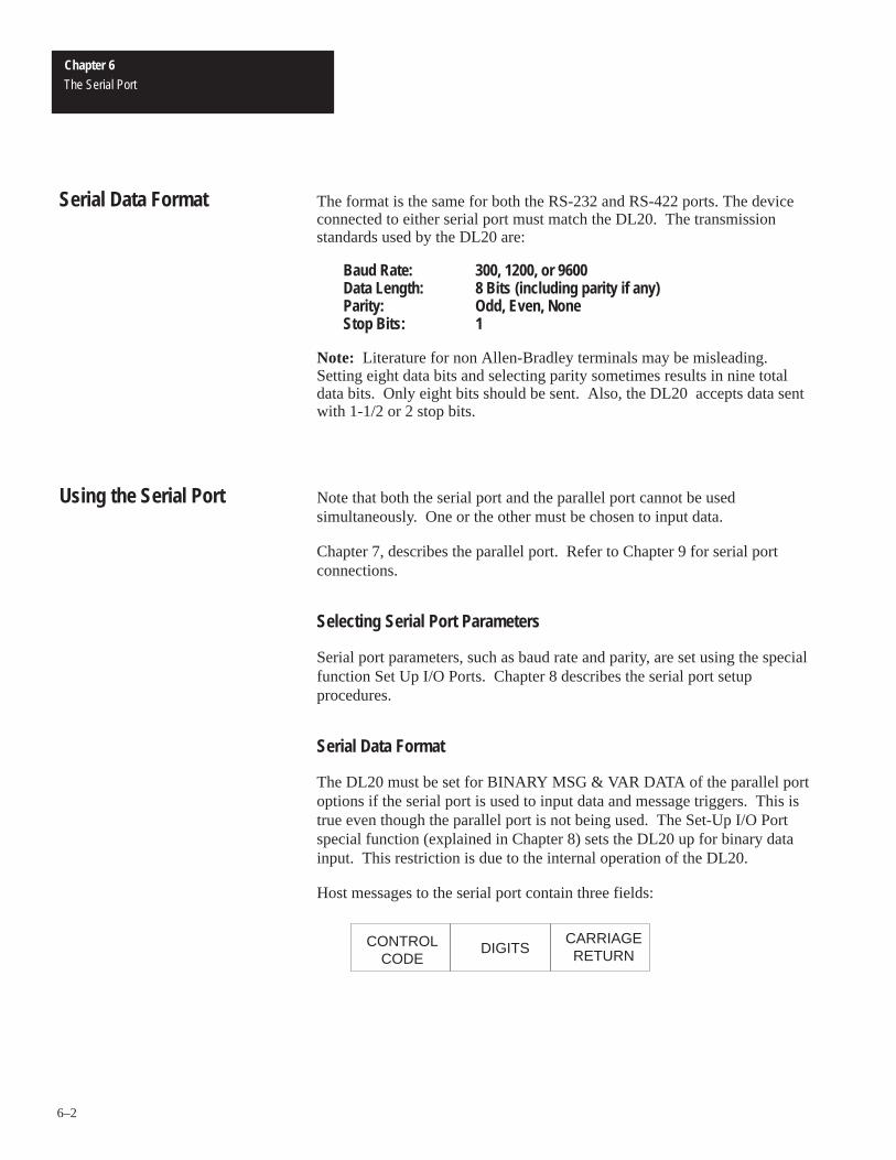
Chapter 6The Serial Port
6–2
The format is the same for both the RS-232 and RS-422 ports. The deviceconnected to either serial port must match the DL20. The transmissionstandards used by the DL20 are:
Baud Rate: 300, 1200, or 9600Data Length: 8 Bits (including parity if any)Parity: Odd, Even, NoneStop Bits: 1
Note: Literature for non Allen-Bradley terminals may be misleading. Setting eight data bits and selecting parity sometimes results in nine totaldata bits. Only eight bits should be sent. Also, the DL20 accepts data sentwith 1-1/2 or 2 stop bits.
Note that both the serial port and the parallel port cannot be usedsimultaneously. One or the other must be chosen to input data.
Chapter 7, describes the parallel port. Refer to Chapter 9 for serial portconnections.
Selecting Serial Port Parameters
Serial port parameters, such as baud rate and parity, are set using the specialfunction Set Up I/O Ports. Chapter 8 describes the serial port setupprocedures.
Serial Data Format
The DL20 must be set for BINARY MSG & VAR DATA of the parallel portoptions if the serial port is used to input data and message triggers. This istrue even though the parallel port is not being used. The Set-Up I/O Portspecial function (explained in Chapter 8) sets the DL20 up for binary datainput. This restriction is due to the internal operation of the DL20.
Host messages to the serial port contain three fields:
DIGITSCARRIAGERETURN
CONTROLCODE
Serial Data Format
Using the Serial Port

Chapter 6The Serial Port
6–3
The control code indicates whether the data is a message number or avariable. The ASCII string represents the message number or variable. Forexample, the number 4,286 would be sent out like this:
ASCII 4 2 8 6
Decimal Equivalent: 52 50 56 54
Hex Equivalent: 34 32 38 36
Octal Equivalent: 64 62 70 66
If the data is a message number, it must contain one or more digits. If itcontains more than four digits, only the last four are accepted. If the numberinput is greater than 1022 (the highest message number) it is ignored. Zero isalso ignored.
If the data is a variable, it also must contain one or more digits. If thenumber contains more than five digits, only the last five sent are accepted. Inaddition, the first character of the field may be a plus or minus sign. Thenumber is assumed to be positive if no sign is sent. The highest numberaccepted is +32,767 and the lowest is -32,768. All other characters in thisfield are ignored, including spaces. For example, these two strings areequivalent:
ASCII - 2 2
Decimal Equivalent: 45 50 50
Hex Equivalent: 2D 32 32
Octal Equivalent: 55 62 62
ASCII (sp) - 2 q 2
Decimal Equivalent: 32 45 50 113 50
Hex Equivalent: 20 2d 32 71 32
Octal Equivalent: 40 55 62 161 62
Important: Sending three consecutive [Esc] characters (decimal 27, hex 1B,octal 33) takes the DL20 out of run mode.
All data entered must be followed by the carriage return character (decimal13, hex D, octal 15). The DL20 queues the data following receipt of thecarriage return.

Chapter 6The Serial Port
6–4
Serial Data Example
Here is an example of a message containing variables, which is triggeredusing the serial link. The example message (number 4) is:
Voltage = ↑ , current = ↑
To trigger this message, the following strings are sent:
ASCII (Ctrl V) 4 1 6 0 [Return]
Decimal Equivalent: 22 52 49 54 48 13
Hex Equivalent: 16 34 31 36 30 0D
Octal Equivalent: 26 64 61 66 60 15
This queues up 4160 as the “voltage” value.
ASCII (Ctrl V) 1 2 0 0 [Return]
Decimal Equivalent: 22 49 50 48 48 13
Hex Equivalent: 16 31 32 30 30 0D
Octal Equivalent: 26 61 62 60 60 15
This queues up 1200 as the “current” value.
ASCII (Ctrl T) 4 [Return]
Decimal Equivalent: 20 52 13
Hex Equivalent: 14 34 0D
Octal Equivalent: 24 64 15
This queues up a trigger for message number 4, which causes this message tobe displayed:
Voltage = 4160, Current = 1200
Note: Don’t forget that the DL20 must be set up for BINARY MSG & VARDATA of the parallel port options for serial port queuing to work. This isselected from the special functions menu.
Using the Serial Port
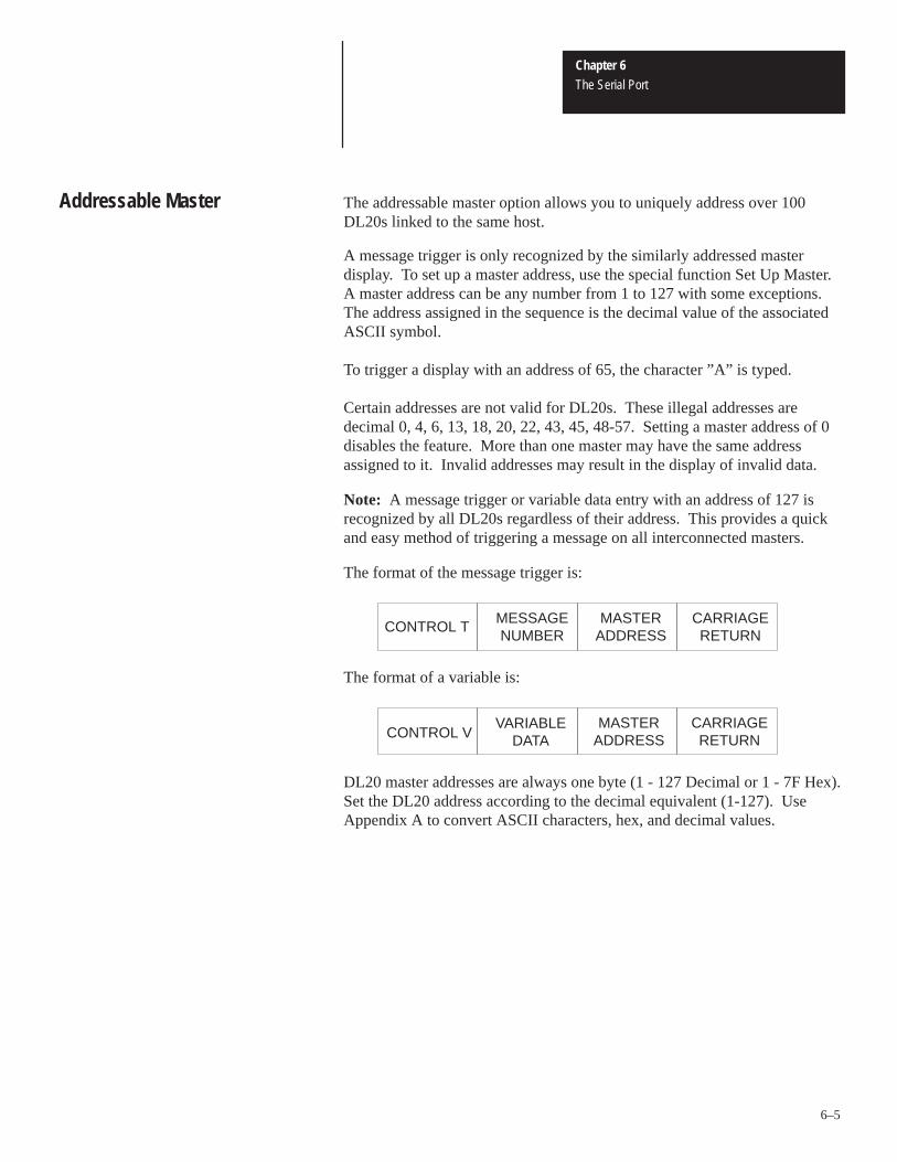
Chapter 6The Serial Port
6–5
The addressable master option allows you to uniquely address over 100DL20s linked to the same host.
A message trigger is only recognized by the similarly addressed masterdisplay. To set up a master address, use the special function Set Up Master.A master address can be any number from 1 to 127 with some exceptions. The address assigned in the sequence is the decimal value of the associatedASCII symbol.
To trigger a display with an address of 65, the character ”A” is typed.
Certain addresses are not valid for DL20s. These illegal addresses aredecimal 0, 4, 6, 13, 18, 20, 22, 43, 45, 48-57. Setting a master address of 0disables the feature. More than one master may have the same addressassigned to it. Invalid addresses may result in the display of invalid data.
Note: A message trigger or variable data entry with an address of 127 isrecognized by all DL20s regardless of their address. This provides a quickand easy method of triggering a message on all interconnected masters.
The format of the message trigger is:
MESSAGENUMBER
MASTERADDRESS
CARRIAGERETURN
CONTROL T
The format of a variable is:
CONTROL VVARIABLE
DATAMASTER
ADDRESSCARRIAGERETURN
DL20 master addresses are always one byte (1 - 127 Decimal or 1 - 7F Hex).Set the DL20 address according to the decimal equivalent (1-127). UseAppendix A to convert ASCII characters, hex, and decimal values.
Addressable Master

Chapter 6The Serial Port
6–6
When DL20s are connected on an RS-422 network, the port must be set as aninput using the Set Up Master special function. Since DL10 slaves areaddressed using the RS-422 port as an output, using DL20s as addressablemasters precludes the use of this port for sending data out to DL10 slaves.
Entering Slave Mode
Enable the slave mode by sending the DL20 the following control sequence,while in the run mode:
[CTRL D] [Address] [Return]
Exiting Slave Mode
While in the slave mode, the DL20 will not respond to message numbertriggers. To exit the slave mode, send the following control sequence:
[CTRL S] [Address] [Return]
Note: If the DL20 is powered down in the slave mode, it will power up inthe normal run mode, not slave mode.
Slave Mode Protocol
Slave mode protocol is as follows.
SLAVEADDRESS
LINENUMBER
CARRIAGERETURN
20 DISPLAYCHARACTERS
1. Send the 20 display characters. Any valid ASCII character, upper orlowercase, can be sent. Previously described control codes do not apply.
2. Send the address. This is a one-byte character, ranging anywhere from 1through 127 decimal (1 through 7F hex). If the address is 65, type thecharacter ”A”.
Note: Restrictions for address byte are the same as described previouslyfor the addressable master feature. Any packet containing the address127 is received by all DL20s, regardless of their address.
3. Send the line number. Valid line numbers are line 1 through line 4. Sendthe decimal equivalent values not the ASCII value:
Line 1 = CTRLALine 2 = CTRLBLine 3 = CTRLCLine 4 = CTRLD
4. Send the carriage return [Return].
Slave Mode Control Codes
There are certain control codes that slave DL20s respond to:
Slave Mode

Chapter 6The Serial Port
6–7
Control F is a flash code. If you want flashing characters, send a control Fwith the 20 character packet. Every character on the specified line will flash.A second control F cancels flash mode.
Control R is the reset command. After receiving a control R within the 20character packet, all the data registers in the DL20 are cleared. For example,if you were to send 10 characters, then a control R, you could then send 20more characters followed by the slave address, followed by the line number,followed by a carriage return. The 20 characters that you sent would bedisplayed on the appropriate DL20. The ten characters sent before thecontrol R would be lost. Control R also resets the flash status to nonflash.
Important: Send a control R to all DL20s when the host controller powersup, because when a serial port powers up it may inadvertently transmiterroneous data.
Slave Mode Baud Rate
The current address and baud rate are displayed on power up. The baud rateof the DL20s must match the baud rate of the host controller. There are threebaud rates: 300, 1200, and 9600 baud. Generally, any of these can be used.However, it is possible that some host devices could be programmed totransmit too many characters too fast at 9600 baud. If you do find a problem,change the rate to 1200 baud, as most users have found that to be anacceptable rate.
Slave Mode Individual Relay Control
Turn off relays in individual slave displays on an RS-422 network by sendingthe command sequence:
[Slave Address] [Line Number] [Return]
Line number 48 (ASCII 0) turns the relay on and line number 49 (ASCII 1)turns the relay off. One possible use for this feature is to signal an incomingmessage by connecting a bell or light to the relay.
!ATTENTION: The relay must only be used for the annunciator,not control functions.
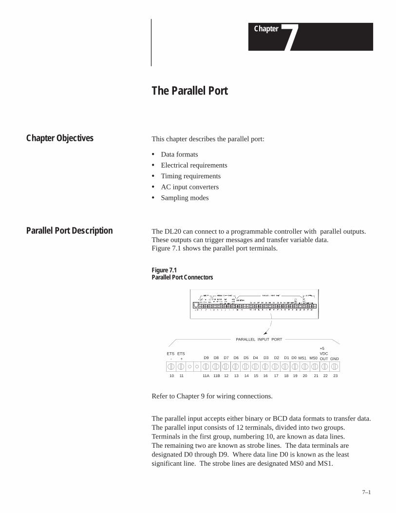
A–B 7Chapter
7–1
The Parallel Port
This chapter describes the parallel port:
• Data formats
• Electrical requirements
• Timing requirements
• AC input converters
• Sampling modes
The DL20 can connect to a programmable controller with parallel outputs.These outputs can trigger messages and transfer variable data. Figure 7.1 shows the parallel port terminals.
Figure 7.1Parallel Port Connectors
ETS -
ETS +
PARALLEL INPUT PORT
MS1 MS0
+5 VDC OUT GND
11A 11B 12 13 14 15 16 17 18 19
D9 D8 D7 D6 D5 D4 D3 D2 D1 D0
10 11 20 21 22 23
Refer to Chapter 9 for wiring connections.
The parallel input accepts either binary or BCD data formats to transfer data.The parallel input consists of 12 terminals, divided into two groups. Terminals in the first group, numbering 10, are known as data lines. The remaining two are known as strobe lines. The data terminals aredesignated D0 through D9. Where data line D0 is known as the leastsignificant line. The strobe lines are designated MS0 and MS1.
Chapter Objectives
Parallel Port Description

Chapter 7The Parallel Port
7–2
Figure 7.2 illustrates a typical example of using discrete I/O outputs with theDL20 parallel port:
Figure 7.2Using Discrete Outputs With the Parallel Port
+
-
D9 D8 D7 D6 D5 D4 D3 D2 D1 D9 MS0 MS1 GND
11A 11B 12 13 14 15 16 17 18 19 21 20 23 TerminalNumber
Terminal BlockDesignation
Power Supply5-30 VDC
(Observe DCPolarity)
PC Outputs (12)
DL20 Parallel Port
Logic Levels
Data line D0 can have a value of either 0 (ground level) or 1 (voltagepresent). The convention of having voltage representing a 1 and groundrepresenting a 0, is known as positive logic. The opposite convention isknown as negative logic. The DL20 can accept either.
Each parallel input understands two voltage levels: On or Off. There is alsoan indeterminate state when the voltage level is between On and Off. Table 7.A shows the voltage levels and their logic values for input terminalsD0-D9 and strobe lines MS0 and MS1.
Using the Parallel Port

Chapter 7The Parallel Port
7–3
Table 7.AVoltage Levels for Each Logic State (Typical Input Resistance = 10K Ohms)
Voltage Range Low True Logic Value High True Logic Value
0-1.5 VDC 1 or ON 0 or OFF
1.5 - 3.5 VDC Indeterminate Indeterminate
3.5 - 30 VDC 0 or OFF 1 or ON
As Table 7.A illustrates, the DL20 can accept high true (higher voltagelevel=1) or low true (lower voltage level=1) logic. Chapter 8 explains howto set parallel port logic levels. Choose whichever logic level best suits yourapplication.
Note: The Allen-Bradley TTL Output Module (1771-OG), DC OutputModule (1771-OB), or AC Output Module (1771-OA) can be used to drivethe parallel port.
Binary vs. BCD
You can use separate data modes for input message triggers and variableswhen using the parallel port. Message triggers can be in binary and variabledata can be in BCD or vice versa. This means you could input variables inBCD format, which may be easier to use, and the message triggers could bein binary, which provides access to the full 1022 message capacity. Selectthe data modes using the special functions menu as described in Chapter 8.
Each numbering system, binary or BCD, has its own merits. Your choicewill often be based on the format used by the host. However, binary valuesprovide certain advantages:
• Range of binary message triggers is from 1 - 1022. Range of BCD message triggers is from 1 - 399.
• Variable range for binary values is -32,768 through 32,767.Variable range for BCD values is 0 through 9,999.
Also, it is not possible to represent negative numbers using BCD format.
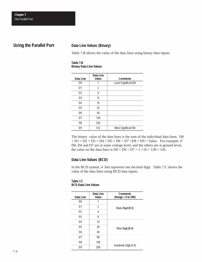
Chapter 7The Parallel Port
7–4
Data Line Values (Binary)
Table 7.B shows the value of the data lines using binary data inputs.
Table 7.BBinary Data Line Values
Data LineData Line
Value CommentsD0 1 Least Significant Bit
D1 2
D2 4
D3 8
D4 16
D5 32
D6 64
D7 128
D8 256
D9 512 Most Significant Bit
The binary value of the data lines is the sum of the individual data lines: D0+ D1 + D2 + D3 + D4 + D5 + D6 + D7 +D8 + D9 = Value. For example: ifD0, D4 and D7 are at some voltage level, and the others are at ground level,the value on the data lines is D0 + D4 + D7 = 1 +16 + 128 = 145.
Data Line Values (BCD)
In the BCD system, 4 bits represent one decimal digit. Table 7.C shows thevalue of the data lines using BCD data inputs.
Table 7.CBCD Data Line Values
Data LineData Line
ValueComments
(Range = 0 to 399)D0 1
D1 2 Ones Digit (0-9)D2 4
Ones Digit (0-9)
D3 8
D4 10
D5 20 Tens Digit (0-9)D6 40
Tens Digit (0-9)
D7 80
D8 100n s igi 3
D9 200Hundreds Digit (0-3)
Using the Parallel Port

Chapter 7The Parallel Port
7–5
Parallel Port Strobe Lines
If the DL20 receives a value like 145, this could mean either a variable 145or a message number 145. The function of the strobe lines (MS0 and MS1)is to tell the DL20 what to do with information on the data lines (D0-D9).
When strobing over a variable, the high order data should be strobed overfirst. The variable will be queued up after the low byte data is strobed in.
Note: If the variable is in the range of 0 - 255 for binary or 0 - 99 for BCD,only the low order data needs to be strobed in. The DL20 will assume thatthe high order data is zero.
MS0 and MS1 qualify and identify the data lines. The process of using theselines to transfer data to the DL20 is known as strobing in data. There arefour possible types of strobes that can occur with these two lines:
Table 7.DStrobe Commands
Strobe LineMS0
Strobe LineMS1 Name Strobe Command
0 0 NULL Ignore Data Lines
1 0 LDAT Data lines are least significantbyte of variable.
0 1 HDAT Data lines are most significantbyte of variable.
1 1 MSGA Data lines are a messagenumber.
NULL or MSGAThe NULL tells the DL20 to ignore the data lines. The fourth strobe,MSGA, tells the DL20 to put the value of the data lines into the messagequeue.
LDATLDAT means the least significant byte of a variable is being strobed in.Variables are usually sixteen bits in size or four BCD digits long. Since thereare only ten (eight used for variable data) wires in the data group, thevariable must be strobed over in two steps. The two values strobed in arethen added together.
HDATHDAT means that the most significant byte is being strobed in. The datalines are interpreted a little differently this time. Table 7.E shows how thedata lines are interpreted using binary values. Table 7.F shows the valueswhen using BCD values.

Chapter 7The Parallel Port
7–6
Table 7.EBinary Data Line Values Using HDAT Strobe
Data Line ValueD0 256
D1 512
D2 1024
D3 2048
D4 4096
D5 8192
D6 16384
D7 Sign Bit: 0 = Positive 1= Negative
D8 D8 and D9 are not used when variable data is strobed in. in s
D9Set both lines to 0.
The value is the sum of D0 through D6: D0 + D1 + D2 + D3 + D4 + D5 +D6 = Value. The seventh wire, D7, is called the sign bit -- numbers can bepositive or negative. The value read during the LDAT strobe is added to thevalue read during the HDAT strobe to obtain the value of the variable from-32,768 to +32,767. Negative numbers are interpreted as two’s complimentvalues by the DL20 and should be transmitted that way. Most programmablecontrollers use two’s compliment values and no conversion is required.
In the BCD numbering system, the data lines are also interpreted differently.When the HDAT portion of the variable is being strobed in, the lines stillrepresent two BCD digits; this time the digits are the hundred and thousandplaces of the desired variable. Table 7.F defines the new digit weights:
Table 7.FBCD Data Line Values Using HDAT Strobe
Data LineData Line
Value CommentD0 100
D1 200 Hundreds Digit (0-9)D2 400
Hundreds Digit (0-9)
D3 800
D4 1000
D5 2000 Thousands Digit (0-9)D6 4000
Thousands Digit (0-9)
D7 8000
D8 D8 and D9 are not used wheni is s in
D9variable data is strobed in. Set both lines to 0.
Using theParallel Port

Chapter 7The Parallel Port
7–7
Edge Triggered Strobe
Note: Refer to event driven sampling in this chapter for a description of howto use the ETS inputs.
The edge triggered strobe (ETS) is typically used with non Allen-Bradleyprogrammable controllers. The DL20 can be set up to either look at the dataand strobe lines periodically (time-driven sampling); or based on a signalpresent on edge triggered strobe (event-driven sampling).
The edge triggered strobe is especially useful with non Allen-Bradleyprogrammable controllers which support word I/O modules. These modulestypically multiplex two or more channels onto one set of data lines. A strobeis brought out for each channel; a channel’s strobe becomes active when datafor that channel is present on the data lines.
Edge triggered strobe does not alter the values present on the data lines, nordoes it affect their interpretation.
Unchanged Data Rejection
When data is read at the parallel port, a copy is saved. If the next reading isthe same, the reading is ignored. This prevents a single message from beingread multiple times.
For example, if the sampling time is 4 and the debounce time is 1, theparallel port is scanned about 100 times per second. If the control systemchanged the data on the parallel port from null to trigger message 12 and heldthe trigger for 100 milliseconds before returning to null, the message wouldbe displayed once, not ten times, even though the parallel port will havebeen sampled ten times.
Chapter 7The Parallel Port
7–8
The parallel input circuit allows inputs to accept DC input voltages from 5 to30V. An input voltage of 120VAC 60Hz is also accepted if a Parallel InputConverter (Catalog No. 2706-NG1 or NG2) is installed.
Almost all programmable controller output modules have some leakagecurrent in the off state. The parallel inputs on the DL20 are designed toignore this output leakage current. The Parallel Input Converter is especiallyinsensitive to the larger levels of leakage current that typically come fromAC output modules.
!ATTENTION: The Parallel Input Converters (Catalog No.2706-NG1 or 2706-NG2) cannot accept 220/240 VAC. If 220/240 VAC is applied, damage to the Parallel InputConverter will occur.
The DL20 can read data on the parallel port two different ways:
• Time-Driven SamplingReads the parallel port periodically.
• Event-Driven SamplingReads the parallel port whenever a transition occurs on the edge triggeredstrobe (ETS) input (terminals 10 and 11). This method is slightly moredifficult to implement with a programmable controller’s discrete I/O thantime-driven sampling, however it may allow slightly faster input.
Choose the method most suitable to your application using the Set Up I/OPorts special function as described in Chapter 8.
Input Converters
Parallel PortSampling Methods

Chapter 7The Parallel Port
7–9
Event driven sampling uses the edge triggered strobe (ETS) input. Terminal10 is the ETS - and Terminal 11 is the ETS+ (1.5-15VDC). The DL20 readsdata on the parallel port on either the rising edge or falling edge (one or theother - not both) as selected in the special functions menu (Set Up I/O Ports).Data must be present on the parallel data port when the edge occurs. Thedata must remain stable for at least 2 milliseconds after the edge occurs. Nomore than 50 edges per second should be triggered on the ETS input. Also,since data is sampled only once with this method, only DC input ispermissible on the parallel input. When using AC modules, we recommendthat data is at the parallel port at least 34 milliseconds before the ETS ischanged.
Note: Strobe line transitions, either from OFF to ON, or from ON to OFF,should occur in less time than the debounce time for DC sampling or in lessthan 1 millisecond for AC sampling.
Important: If AC voltage is used, it could be inadvertently sampled duringthe zero crossover of the AC waveform of the Parallel Input Converter(Catalog No. 2706-NG1, -NG2 Series A or B).
The ETS input (terminal 11) is measured with respect to ETS common(terminal 10). ETS common is isolated. This input presents a DC load of470 ohms and 2 diode drops (0.7 Volts per diode).
Terminal 23 (GND) is a ground reference for the data lines D0 through D9,MS0, MS1, and +5VDC out. If needed, ETS common (terminal 10) can beexternally connected to the ground reference (terminal 23).
Table 7.G shows the voltage and current requirements of the ETS inputs.
Table 7.GETS Voltage and Current Requirements
ETS Input Logic Level ETS Input Current Requirements
Voltage Range Logic Level Voltage Current
0-1.5 VDC 0 or OFF 4.0 5 mA
1.5-4.0 VDC Indeterminate 5.0 7 mA
4.0-15 VDC 1 or ON 12.0 22 mA
15.0 28 mA
Important: A TTL output module cannot be used to trigger the ETS line. It cannot supply sufficient current at 5VDC.
Event Driven Sampling
Chapter 7The Parallel Port
7–10
Because it does not require an additional ETS rising or falling edge to readDL20 data lines, time-driven sampling is the recommended way of looking atDL20 data lines. When time-driven sampling is selected, the DL20 looks atthe data lines periodically. The time interval used by the DL20 is set usingthe special functions menu described in Chapter 8.
Time-Driven Sampling Methods
AC and DC sampling can be used. Both sampling methods reduce falsemessage triggering and invalid data. When DC sampling is selected, you canselect the debounce time (see Chapter 8).
AC sampling is required when using a Parallel Input Converter (Catalog No.2706-NG1, -NG2 Series A or B).
DC sampling is required when using a Parallel Input Converter (Catalog No.2706-NG1, -NG2 Series C or later). These converters convert the AC signalto DC.
AC Sampling
The DL20 uses a special AC sampling method when AC sampling is chosenand the Series A or B Parallel Input Converters are used. See Appendix Hfor more information.
Data Hold TimeFor AC data input to be recognized on the parallel port, it must be presentand unchanging for a minimum of 180ms (Series A and B Parallel InputConverters).
AC Sampling RestrictionsThe frequency of AC is approximately 60 Hz. The voltage must fall withinthe range of 108-132 VRMS. The AC on all inputs must be in phase.
Note: The AC power input used to power the device does not need to be inphase with the AC on the parallel port inputs. A Parallel Input Converter(Catalog No. 2706-NG1, -NG2) is required for AC parallel inputs.
Time Driven Sampling

Chapter 7The Parallel Port
7–11
DC Sampling
The parallel port is always sampled more than once and all readings mustagree. This provides a variable degree of insensitivity to noise on the datalines.
For example, assume you are sending the binary data 010 and change it to100. For a very brief time the data lines may assume the intermediate stateof 000 or 110 before settling at 100, the desired number. If the parallel portwas sampled only once, the erroneous intermediate state could be readinstead of correct data.
DC Sampling DebounceThe debounce process works like this: during each scan, the parallel port isread, and the debounce sampling is started. Every 1/512 second until thedebounce count is satisfied, the parallel port is read again. All readings mustagree, or the data is ignored. For example, if the debounce value is set to 2,the parallel port will be read 3 times (having one initial reading) and the tworeadings must match the initial reading for data to be accepted.
Data Hold TimeFor DC data input to be recognized on the parallel port, it must be presentand unchanging for a minimum of 15 milliseconds when using the defaultscan rate and debounce.
Note: The Parallel Input Converter Series C or later uses a DC samplingmethod. For the data input to be recognized on the parallel port, it must bepresent and unchanging for 100 ms.

Chapter 7The Parallel Port
7–12
Variable data is transferred up to eight bits at a time. The high order data bitsare strobed over, then the low order data bits are strobed over. Only then isthe data queued up. The strobing order is important; high order data bitsmust be strobed in first. The timing of a typical data transfer using binarydata could look like this:
t7 t8t1 t2 t3t0 t6t5t4
D0
D1
D2
D3
D4
D5
D6
D7
D8
D9
MS0
MSI
t4: The data lines can now change to indicate the low order byte.
The DL20 will ignore the data lines because both MS0 and MS1
are OFF. t4 can last for any length of time.
t5: Strobe line MS0 is turned ON.
t6: The data lines are latched in and they are interpreted as low
order data because MS1 is OFF and MS0 is ON. The data read
in is equal to the sum of the values of the bits. We can look at
the table 7.B and see that the value strobed over is 64
+ 16 or 80. The DL20 will now queue up a variable since both
high order data and low order data have now been strobed in.
The value of the variable queued will be 10,752 + 80 or 10, 832.
t7: Strobe line MS0 is turned OFF.
t8: As long as MS0 and MS1 are OFF, the DL20 ignores the data
lines.
t0: The binary code for 10,832 is 0010 1010 0101 0000. During t0
the first eight bits of the data word are set up on the parallel
input lines: D5, D3, and D1 are ON and D7, D6, D4, D2 and D0
are OFF. Since both strobe lines are OFF, the DL20 ignores
the data lines.
t1: Strobe line MS1 is turned ON, strobe line MS0 is left OFF. This
tells the DL20 that we are entering high order data.
t2: The data lines are latched in and they are interpreted as high
order data during the period t2 because MS1 is ON and MS0 is
OFF. The data read in is equal to the sum of the values of the
bits. We can look at the table 7.E and see that the
value strobed over is 8,192 + 2,048 + 512 or 10,752. t2 should
be long enough so data can be sampled by the DL20. As noted
before, this sampling time is user-selected. If edge triggered
sampling is used, the edge should occur during t2.
t3: Strobe line MS1 is turned OFF.
Transferring Variable Data

Chapter 7The Parallel Port
7–13
Message number 12 contains two variables.
PARTS COUNT = ↑ REJECTS = ↑
First, transfer over the parts count, 8 bits at a time. Then transfer over thereject count, 8 bits at a time. Lastly, transfer over the message number,which triggers the message. The timing of the message would look like this:
t10t9t2 t3t1t0 t8t7t6t5t4
D0
D1
D2
D3
D4
D5
D6
D7
D8
D9
MS0
MSI
t0: The high order bits of the first variable are set up on the datalines; they are zero in this case, then MS1 is turned ON.
t1: The DL20 stores a zero, the value on the data lines, as the highorder byte of a variable. Steps t0 and t1 are optional; if loworder data is strobed in without high order data having beenstrobed in, the DL20 will assume that the high order data is zero.
t2: MS1 is turned OFF; then the low order bits of the first variableare set up on the data lines, 100 in this case, then MS0 is turnedON.
t3: The DL20 stores 100, the value on the data lines, as the loworder byte of a variable. Both the high order and low orderportion of a variable have now been read in, so the DL20 queuesthe variable up. In this case, the value 100 is queued up.
t4: First MS0 is turned OFF; then the high order bits of the secondvariable are set up on the data lines, zero in this case; the MS1is turned ON.
t5: The DL20 stores zero, the value on the data lines, as the highorder byte of a variable. Once again, t4 and t5 are optional.
t6: First MS1 is turned off; then the low order bits of the secondvariable are set up on the data lines, 8 in this case; then MS0 isturned on.
t7: The DL20 stores 8, the value on the data lines, as the low orderbyte of a variable. Both the high order and low order portion of avariable have now been read in, so the DL20 queues thevariable up. In this case, the variable 8 is queued up.
t8: First MS0 is turned OFF; then the data lines are set to the value12, which is the message number we wish to trigger; then bothMS0 and MS1 are turned ON.
t9: The value on the data lines, 12, is queued up as a messagetrigger.
t10: MS0 and MS1 are turned OFF. The DL20 ignores the data lines.
Example Message Triggerwith Variable Data

Chapter 7The Parallel Port
7–14
If messages don’t contain variable data, the number of outputs can bereduced. Since no variable data is transferred, both strobe lines are alwayszero, or always one. In addition, some data lines (D0 - D9) could beeliminated depending on the highest message number used. Figure 7.3 illustrates this method.
Figure 7.311 Ouput Configuration
+
-
D9 D8 D6 D5 D4 D3 D2 D1 D0 MS0 MS1 GND
11A 11B 12 13 14 15 16 17 18 19 21 20 23 TerminalNumber
Terminal BlockDesignation
Power Supply5-30 VDC
(Observe DCPolarity)
PC Outputs (11)
D7
You can further reduce the output requirements by tying the strobe lines highas shown in Figure 7.4
Figure 7.410 Output Configuration
Tie TogetherFor HIGH
TRUE LogicOnly
+
-
D9 D8 D7 D6 D5 D4 D3 D2 D1 D0 MS0 MS1 GND
11A 11B 12 13 14 15 16 17 18 19 21 20 23 TerminalNumber
Terminal BlockDesignation
Power Supply5-30 VDC
(Observe DCPolarity)
PC Outputs (10)
Reducing Host Output Requirements

Chapter 7The Parallel Port
7–15
You can tie the strobe lines high because message zero is ignored. Keep alldata lines at zero, until you want to trigger a message. The last message isonly triggered once --no matter how long the data lines stay in their state(DL20 rejects unchanging data). To trigger the same message twice in a row,the message must be triggered, the data lines must return to a zero state, themessage can then be retriggered. The following diagram shows howmessage 7 could be triggered once and message 12 triggered twice using theconnections shown in Figure 7.4.
t3t2t1t0 t9t8t7t6t5t4
D0
D1
D2
D3
D4
D5
D6
D7
D8
D9
MS0
MSI
t6: A zero is presented to the DL20. Twelve cannot be presentedhere, because the DL20 will not queue the same message twicein a row, as long as MS0 and MS1 remains ON. In this example,MS0 and MS1 are always ON.
t7: The data lines change state, from zero to twelve.
t8: The message trigger twelve is queued up.
t9: The last message has been triggered, the data lines may remain in their previous state or they may change back to zero.
t0: The value on the data lines is zero, the DL20 ignores this value because there is no message zero.
t1: The data lines change state, from zero to seven.
t2: The message trigger seven is queued up.
t3: The data lines change state, from seven to twelve.
t4: The message trigger twelve is queued up.
t5: The data lines change state, from twelve to zero.

Chapter 7The Parallel Port
7–16
In these examples where MS0 AND MS1 are not strobed, the data lineschange state quickly, or the DL20 could read erroneous data. The DL20samples the data and strobe lines at the set scan rate. The lines are alwaysresampled at least twice, depending on the debounce time setting, andwhether AC or DC sampling is selected. All readings must agree, or theDL20 will continue to sample them until they do. If the data takes longer tochange than the debounce time, then erroneous data could be entered into theDL20.
Figure 7.5 shows how to reduce output requirements even further. Manyapplications do not require the full 1022 message capability of the DL20. Iffewer messages are required, you need only enough data lines to address allthe messages. The number of messages addressed by n data lines is 2 to thenth power less one. For example, 4 data lines can address 16 - 1, or 15messages. A total of seven messages may be displayed by the exampleshown in Figure 7.5.
Figure 7.53 Output Configuration
Tie TogetherFor HIGH TRUE
Logic Only
Tie TogetherFor LOW TRUE
Logic Only
+
-
D0 D1 D2 D3 D4 D5 D6 D7 D8 D9 MS0 MS1 GND
19 18 17 16 15 14 13 12 11B 11A 21 20 23
Power Supply5-30 VDC
(Observe DCPolarity)
PC Outputs (3)
TerminalNumber
Terminal BlockDesignation
Reducing Host Output Requirements

A–B 8Chapter
8–1
Special Functions
This chapter describes the following special functions:
• Send Messages to Printer
• Load Message to Tape①
• Load Messages from Tape①
• Verify Tape Messages①
• Download Message Data as EPROM File①
• Show Time and Date
• Set Time and Date
• Reset and Self Test
• Set Serial Port①
• Set Parallel Port①
• Debug
• Clear All Messages①
• Set Autorun Message①
• Set Background Message①
• Set Master Address①
• Enable Dynamic Chaining①
• Set Relay for Low Battery Indication①
• View All Edit, Menu, and Special Function Prompts on Slave DL10s①
• Enable Flagging of Triggering Errors①
① Not available if messages are stored in EPROM.
Chapter Objectives

Chapter 8Special Functions
8–2
Figure 8.1 shows the basic menu structure.
Figure 8.1 Special Functions Menu
��� �� ����� ����
�� �� �����
��� ����� ����
���� �����
����� ����� ���
��� �� ��
�� �� �� ������
��� ���
���� ����
�� �� ������
��
�
�
�
�
�
�
�
�
�
��
�
�
�
�
�
�
�
�
�
�&�#(���''���'���#)
��%���%�&�(�$#'���#)
�������#)
�!$� ���#)
������'�('
��&��!�����&�!!�!��$&(���#)
��$*'��(�()'�$�� #%)('
�!��&�������#)
�
�
�+'(�"��%(�$#'���#)
Special Functions Menu
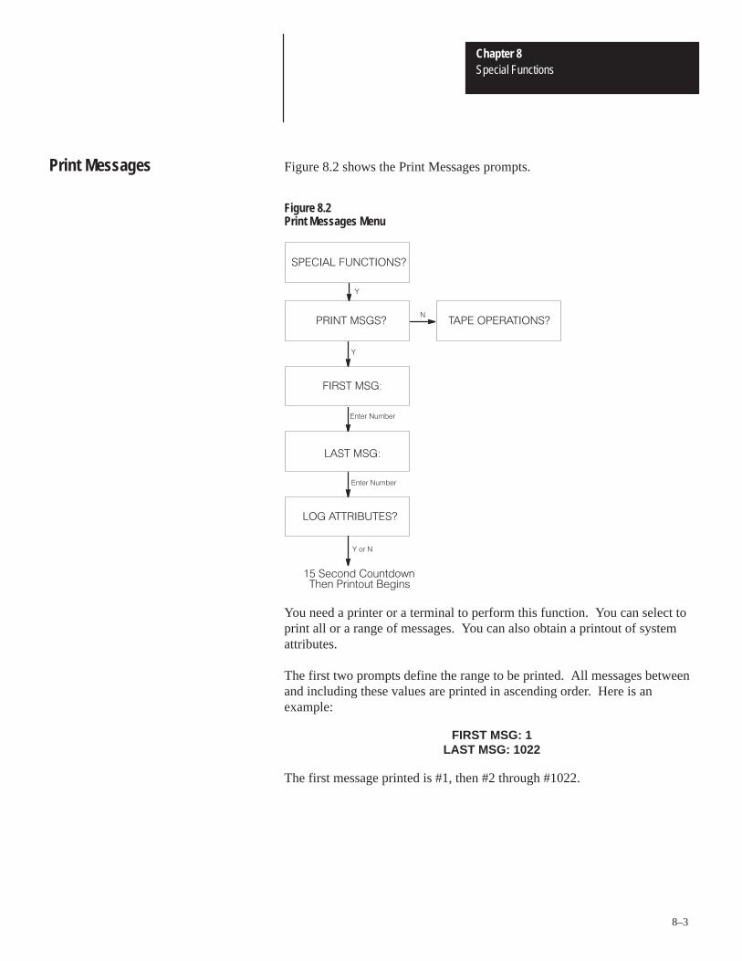
Chapter 8Special Functions
8–3
Figure 8.2 shows the Print Messages prompts.
Figure 8.2Print Messages Menu
����� ���������
����� �����
�
�
�
���� ����
�#�!��$���!
��� ����
�#�!��$���!
�� ����������
�� !��
������ ���� $�#� %�������!��# $#������"
��� ����������
You need a printer or a terminal to perform this function. You can select toprint all or a range of messages. You can also obtain a printout of systemattributes.
The first two prompts define the range to be printed. All messages betweenand including these values are printed in ascending order. Here is anexample:
FIRST MSG: 1LAST MSG: 1022
The first message printed is #1, then #2 through #1022.
Print Messages
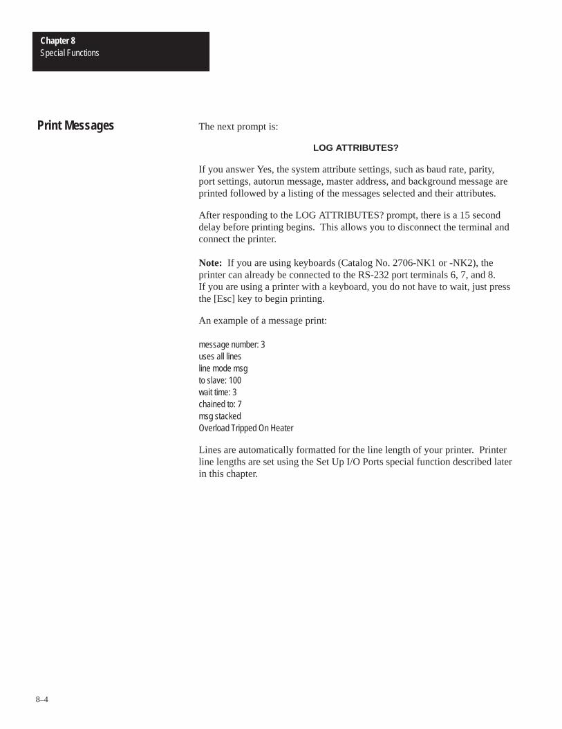
Chapter 8Special Functions
8–4
The next prompt is:
LOG ATTRIBUTES?
If you answer Yes, the system attribute settings, such as baud rate, parity,port settings, autorun message, master address, and background message areprinted followed by a listing of the messages selected and their attributes.
After responding to the LOG ATTRIBUTES? prompt, there is a 15 seconddelay before printing begins. This allows you to disconnect the terminal andconnect the printer.
Note: If you are using keyboards (Catalog No. 2706-NK1 or -NK2), theprinter can already be connected to the RS-232 port terminals 6, 7, and 8.If you are using a printer with a keyboard, you do not have to wait, just pressthe [Esc] key to begin printing.
An example of a message print:
message number: 3uses all linesline mode msgto slave: 100wait time: 3chained to: 7msg stackedOverload Tripped On Heater
Lines are automatically formatted for the line length of your printer. Printerline lengths are set using the Set Up I/O Ports special function described laterin this chapter.
Print Messages

Chapter 8Special Functions
8–5
Figure 8.3 shows the Tape Operations prompts.
Figure 8.3Tape Operations Menu
����� �� ��
���� ���������� ��� ������
�
����� �� �����
��� ���� �����
������ �����
�
��!�� #"���"#!$�#���"
�
��!�� #"���"#!$�#���"
�
��!�� #"���"#!$�#���"
����
������
��� ����%��
�
���� ���� ���
���!��
�
�
����
The tape operations are:
• Write to tape
• Read from tape
• Verify tape
You can perform tape operations using one of the following:
• Allen-Bradley Data Recorder (Catalog No. 1770-SA or -SB)
• EPI STR-LINK II or III
Tape Operations

Chapter 8Special Functions
8–6
Before using the tape special functions, the recorder must be properlyconnected and set up. Refer to Appendix B for instructions.
Note: Make sure that the ECHO ALL TO SLAVE special function is notselected.
The first prompt on the Tape Operations menu is:
ABORT?
Answer Yes to return to EDIT?, otherwise you will see this prompt:
USE 1770-SB?
Answer Yes if you are using an Allen-Bradley Data Recorder or No if youare using a STR-LINK II or III Data Recorder. If you are using anAllen-Bradley Data Recorder, you will see this prompt:
USE 2706 KYBD?
Answer Yes if you are using a keyboard (Catalog No. 2706-NK1, -NK2).When using a 2706 keyboard, you must press the return key to acknowledgethe prompts. If you answer No, the DL20 will assume that you are using aterminal with an RS-232 port and prompt you to disconnect the terminal.
Writing Tapes
When writing a tape, all message data as well as system attributes aretransferred. In addition, special codes for verifying the data are also writtento the tape. The verify operation uses these codes to check the integrity ofthe data.
Reading Tapes
Reading a tape overwrites all messages currently stored in the DL20. Youare prompted twice to make sure that important data is not lost:
SURE? N
and then
POSITIVE? N
If there is not adequate memory available or if the tape is read back with anerror, the following is displayed:
CANNOT READ TAPE
Tape Operations

Chapter 8Special Functions
8–7
Verifying Tapes
Always use the verify after writing a tape or if you question the readability ofa tape. Verify performs a checksum on the tape data and compares thatchecksum with the checksum stored on the tape. If the checksums don’tmatch, the tape fails verification. The data does not have to match the datastored in the DL20. The DL20 displays the results of the operation.
Using Allen-Bradley Data Recorders
Note: See Appendix B for setup and operating instructions.
If you are using an Allen-Bradley Data Recorder (Catalog No. 1770-SA or-SB), you will need a special cable (Catalog No. 2706-NC4). This cable hasa three position toggle switch (Record / Off / Play).
The DL20 prompts you through the tape operation. If you are writing totape, you have 15 seconds to unplug the programming terminal, plug in thedata recorder, press Record on Tape, and place the toggle switch to Record.The display counts down the time.
Using STR-Link II and III Data Recorders
Note: See Appendix B for setup and operating instructions.
After selecting one of the tape operations, you will be prompted:
PRESS REMOTE CONTROLLOAD TAPE - HIT <CR>
Load the tape and press the REMOTE button on the data recorder. Press[Return] and the tape will rewind. After rewinding, the taping begins. TheDL20 displays the status of the tape operation. Press [Esc] to return to themain menu.
Using Data Recorders

Chapter 8Special Functions
8–8
Figure 8.4 shows the Burn EPROM prompts.
Figure 8.4EPROM Operations Menu
�� � � ���������
���� ���
�
�
�
������������� �������
������������� �������
�
��� �� �������
���� � ���������
The DL20 can transfer message data and system attributes to an EPROMfile. The EPROM file can be used to burn an EPROM. When this EPROMis inserted into a DL20, message and system attributes cannot be modified.Use EPROMs as a reliable method of programming multiple DL20s withidentical messages.
Appendix C describes how to transfer the EPROM file. Data is sent as anEPROM file in S record format using the RS-232 port.
Important: EPROMs can only be created from DL20s with 16K memoryprogrammed or less. Make sure the ECHO TO ALL SLAVES specialfunction is not selected when using the EPROM function.
DL20 Operation Using an EPROM
Instructions for installing an EPROM are provided in Chapter 9. After anEPROM is installed in a DL20, it will overwrite the RAM memory. Thereare some restricted modes when using an EPROM:
• DL20s enter run mode on powerup. You cannot enter edit mode.
• The following special functions are not accessible:
Tape Operations
Burn PROM
Clear RAM
Set Up Master
Set Up I/O Ports
Other than these restrictions, the DL20 functions like a DL20 using RAM.
EPROM Programming

Chapter 8Special Functions
8–9
Figure 8.5 shows the Clock Operation prompts.
Figure 8.5Clock Operations Menu
���� �����
��� ����������
�
�
�
�!%*'��"#
�
� �� �����
����� ������
�& ''���'��
��� �������
� �&����%$(!����+����( ������%&���� &��%&#�(��� %)&������%&�������"$)( ���� �%$�
�& ''���'��
�
Use the real time clock to time stamp message logs or to display the currenttime. The Clock Operation special function sets the correct time and date.The time is displayed in the format:
12:33:26 WED FEB 26
Real Time Clock Functions

Chapter 8Special Functions
8–10
For example, to set the clock to 1:34 pm you would answer Yes to the SETCLK? prompt. You are prompted to enter a year.
YR:93
Enter the correct year and press [Return]. You are prompted for a month.
MONTH:2
Enter the correct month and press [Return]. You are prompted for a day ofthe week.
DAY:4
Enter a value 1 through 7 where 1 = Sunday and 7 = Saturday and press[Return]. You are prompted for a format?
24 HOUR FORMAT?
Enter [N] and press [Return] to select 12 hour format. You are prompted foran hour:
HR: 12
Enter [1] [Return] to set the new hour. You will be prompted for AM or PM.
AM? N
Enter [N] and press [Return] to select PM. You are prompted for the minute.
MIN: 59
Enter 34 and press [Return]. You are prompted for the seconds.
SEC: 26
Look at the clock you are using to set the time and enter the current secondsplus an additional 15 seconds. When the time is exactly as set, press[Return]. The DL20 continuously displays the time until you press [Esc].
You can also set the clock using special messages #12 and #13 as describedin Chapter 5.
Important: Once you begin setting the clock, you must finish. Pressing[Esc] does not exit the function.
Real Time Clock Functions
Chapter 8Special Functions
8–11
The Reset Unit special function has the same effect as turning the power offand then back on. After resetting, the DL20 goes through its normalpowerup self test sequence. The reset function provides a convenient methodof making a baud rate change take effect. Figure 8.6 illustrates the resetmenu.
Figure 8.6Reset Operations Menu
� ��� ���������
��� �����
�
�
�
�
�� ��� ��������
�� �� ��� �������
���������
�� ������
Resetting the DL20To reset the DL20, answer Yes to the RESET UNIT? prompt. Press [Return]at the AB TEST MONITOR? prompt to accept the default, No.
Test Monitor FunctionAB Test Monitor provides testing functions when used with specialequipment. A test code (not available to user) is required to enter the mode.If this mode is entered inadvertently, make sure 9600 baud is set and press[9] to exit.
Reset Unit Function

Chapter 8Special Functions
8–12
Figure 8.7 shows the Set Up I/O Ports prompts. Use the Set Up I/O Portsfunction to configure the parallel or serial port.
Figure 8.7Set Up I/O Operations Menu
����� �����
��� �� ��� ������
�
��� ������ �����
�� �� ������
��� �������� ����� �
��� ��� �����
�&)$(��*%#$(�!�$)*(&"
����� ������
�&)$(��*%#$(�!�$)*(&"
���� !�� ��� �"
�&)$(��*%#$(�!�$)*(&"
��� ����� �
�
��� ��� �� �
�'(��
����� ���� �����
�'(��
�����
��� ����� �
�
���� ����� �
�'(��
�� ���� ������
���� ��� �����
���� ��� �����
���� �������
� �����
�'(��
�'(��
�'(��
��� ����� ��� �� �
�
�&)$(��*%#$(�!�$)*(&"
�� ����� ����
�&)$(��*%#$(�!�$)*(&"
�����
��� �� �� �����
���� ����
�&)$(��*%#$(�!�$)*(&"
�'(��
���� ����
Setting Up I/O Port Functions
Chapter 8Special Functions
8–13
Setting Serial Port
After selecting Set Serial Port, you are prompted for the number of nulls.
HOW MANY NULLS: 4
Nulls are do nothing characters sent to the printer or other serial devices aftera carriage return. Slower terminals might require nulls because the carriagetakes some time to return to the first print column. Enter 0 or another valueand press [Return]. You are prompted for the carriage width of your printer.
ENTER LENGTH: 80
Messages are automatically broken into lines that fit the page. You canadjust the carriage width from 20 to 200 characters. Enter a value and press[Return]. You are prompted for the baud rate.
RATE [3, 12, 96]: 3
Enter the baud rate in hundreds and press [Return]. The baud rate changesthe next time power is cycled or the DL20 is reset.
Note: If you change the baud rate, make sure the baud rate of your terminalis changed also.
After entering the baud rate, you are prompted for parity.
SET PARITY? N
The DL20 ignores the parity bit, but is capable of generating it. If youchoose to set parity, you will be prompted for odd or even parity. If neitherodd or even parity is selected, no parity is set. A message displays showingthe parity in effect.
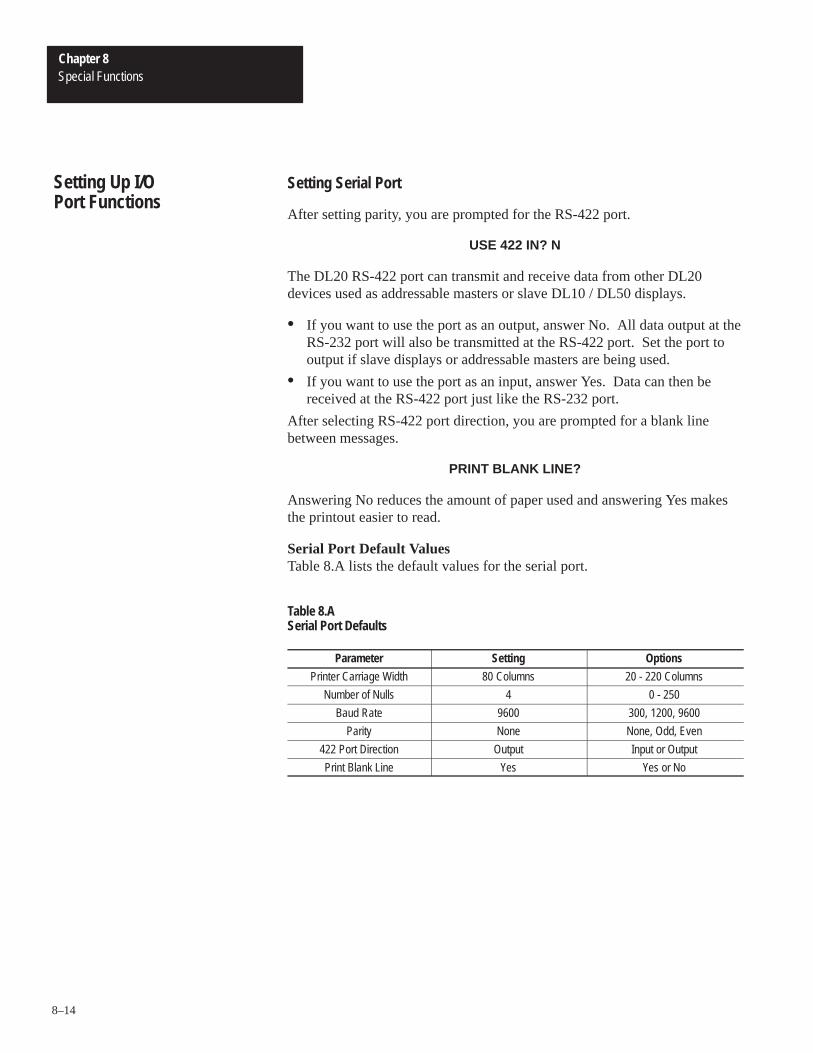
Chapter 8Special Functions
8–14
Setting Serial Port
After setting parity, you are prompted for the RS-422 port.
USE 422 IN? N
The DL20 RS-422 port can transmit and receive data from other DL20devices used as addressable masters or slave DL10 / DL50 displays.
• If you want to use the port as an output, answer No. All data output at theRS-232 port will also be transmitted at the RS-422 port. Set the port tooutput if slave displays or addressable masters are being used.
• If you want to use the port as an input, answer Yes. Data can then bereceived at the RS-422 port just like the RS-232 port.
After selecting RS-422 port direction, you are prompted for a blank linebetween messages.
PRINT BLANK LINE?
Answering No reduces the amount of paper used and answering Yes makesthe printout easier to read.
Serial Port Default ValuesTable 8.A lists the default values for the serial port.
Table 8.ASerial Port Defaults
Parameter Setting Options
Printer Carriage Width 80 Columns 20 - 220 Columns
Number of Nulls 4 0 - 250
Baud Rate 9600 300, 1200, 9600
Parity None None, Odd, Even
422 Port Direction Output Input or Output
Print Blank Line Yes Yes or No
Setting Up I/O Port Functions

Chapter 8Special Functions
8–15
Setting Parallel Port
Data FormatsThe parallel port can be configured to accept either binary or BCD data foreither message triggers or variable data. This allows you to input variables ina BCD format and triggers in a binary format (allows full 1022 messagecapability).
Important: Binary data must be selected if the serial port is being used formessage triggers.
Data SamplingSampling of the data on the parallel port can be either:
• Event driven using an edge triggered strobe (ETS) input
• Time driven using a set sample rate
Logic LevelsThe parallel port can be configured to accept either:
• High true logic where:On state = 1 = voltage across input
• Low true logic where:On state = 0 = no voltage across input
High true logic is the default.
Message PromptsAfter selecting Set Parallel Port, you are prompted for the logic level.
HI TRUE LOGIC? Y
After selecting the logic level, you are prompted for the message data type(binary or BCD).
BINARY MSG DATA? N
You are then prompted for the variable data type (binary or BCD).
BINARY VAR DATA? N
After selecting the data types, you are prompted for the type of data sampling(time or event driven).
TIME SAMPLE? Y
Note: It is recommended that you use time driven sampling unless a nonAllen-Bradley programmable controller with word I/O modules is used.
If you select event driven sampling, you are prompted for the triggertransition (high to low or low to high).
USE HI TO LOW?

Chapter 8Special Functions
8–16
Setting Parallel Port
If you selected time driven sampling, you are prompted for the type of inputsused.
USE NG1/2 SER A,B?
Answer [Y] for AC sampling if you are using:
• A 2706-NG1 or -NG2 Series A or B Parallel Input Converter
Answer [N] for DC sampling if you are using:
• DC inputs
• Catalog No. 2706-NG1 or -NG2 Series C or later Parallel Input Converter
When specifying time driven samples, you must provide a scan rate.
SCAN RATE: 25
The scan rate is the period between samplings in units of 1/512 seconds (1.95ms).
• For DC sampling, the range for the scan rate is 4 to 255 (7.8 ms to 500 ms).
• For AC sampling the range for the scan rate is 28 to 255 (54.6 ms to 500 ms).
The DL20 always samples the data more than once. If all of the samples donot agree, the data is ignored and not scanned again until the next samplingperiod.
If you are using DC inputs or a Parallel Input Converter (Catalog No.2706-NG1, -NG2 Series C or later), you must provide a debounce time:
DEBOUNCE TIME: 2
During the debounce time, data samples are read every 1/512 second (1.95ms). The allowable range is from 1 to 255 (1.95 through 500 ms).Increasing the debounce time provides better noise immunity. Decreasingthe debounce time provides a faster response. The debounce time should be3 less than the scan rate.
Setting Up I/O Port Functions
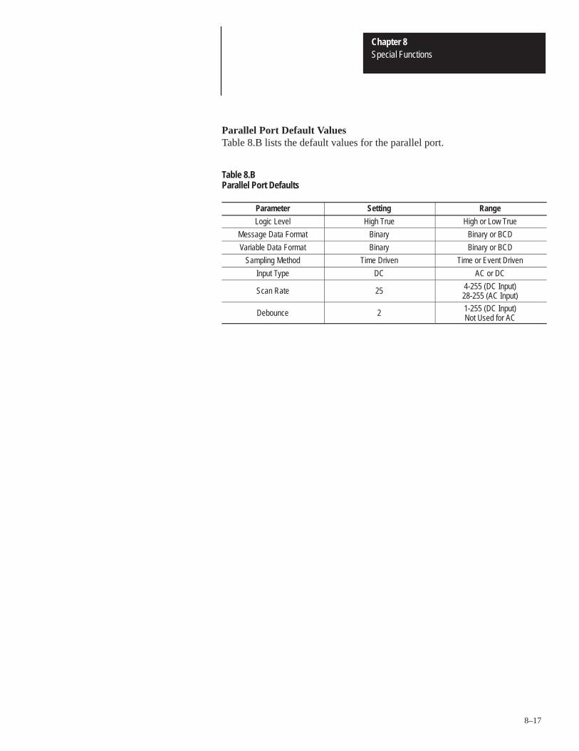
Chapter 8Special Functions
8–17
Parallel Port Default ValuesTable 8.B lists the default values for the parallel port.
Table 8.BParallel Port Defaults
Parameter Setting Range
Logic Level High True High or Low True
Message Data Format Binary Binary or BCD
Variable Data Format Binary Binary or BCD
Sampling Method Time Driven Time or Event Driven
Input Type DC AC or DC
Scan Rate 25 4-255 (DC Input)28-255 (AC Input)
Debounce 2 1-255 (DC Input)Not Used for AC
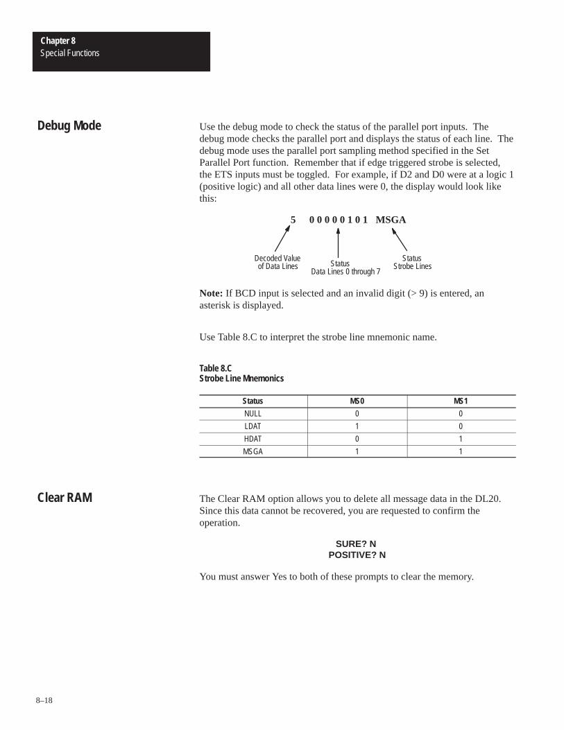
Chapter 8Special Functions
8–18
Use the debug mode to check the status of the parallel port inputs. Thedebug mode checks the parallel port and displays the status of each line. Thedebug mode uses the parallel port sampling method specified in the SetParallel Port function. Remember that if edge triggered strobe is selected,the ETS inputs must be toggled. For example, if D2 and D0 were at a logic 1(positive logic) and all other data lines were 0, the display would look likethis:
5 0 0 0 0 0 1 0 1 MSGA
Decoded Valueof Data Lines
Data Lines 0 through 7
StatusStrobe LinesStatus
Note: If BCD input is selected and an invalid digit (> 9) is entered, anasterisk is displayed.
Use Table 8.C to interpret the strobe line mnemonic name.
Table 8.CStrobe Line Mnemonics
Status MS0 MS1
NULL 0 0
LDAT 1 0
HDAT 0 1
MSGA 1 1
The Clear RAM option allows you to delete all message data in the DL20.Since this data cannot be recovered, you are requested to confirm theoperation.
SURE? N POSITIVE? N
You must answer Yes to both of these prompts to clear the memory.
Debug Mode
Clear RAM
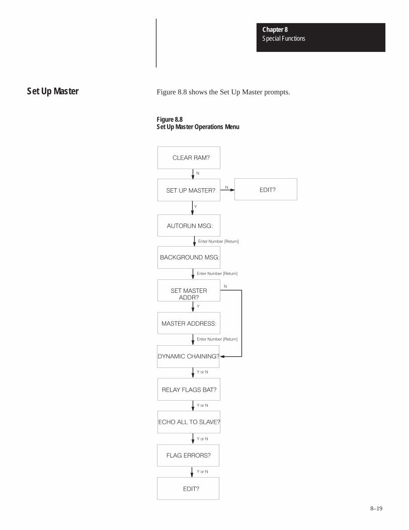
Chapter 8Special Functions
8–19
Figure 8.8 shows the Set Up Master prompts.
Figure 8.8Set Up Master Operations Menu
����� ����
��� �� �������
�
�
������� ���
������
�
��� ��
��!� ��"��� ����!" ��
��� ����� ���
��� �����������
������ ��������
�
��!� ��"��� ����!" ��
��!� ��"��� ����!" ��
������� ��������
����� ��� ����
���� ��� �� ������
�� �������
�����
��� ��
��� ��
��� ��
Set Up Master

Chapter 8Special Functions
8–20
Use the Set Up Master function to:
• Select autorun message
• Select background message
• Set master address
• Enable or disable dynamic chaining
• Set relay to turn on when batteries are low
• Output all prompts and messages to slave displays
• Display error messages
Selecting an Autorun Message
Autorun causes the run mode to be entered on powerup if the DL20 was shutoff in the run mode or if a message EPROM is installed. An autorunmessage can automatically be triggered when the DL20 powers up. Theautorun message is the first message displayed after self tests regardless ofthe message queue or triggers. When setting up the DL20, you will see thisprompt:
AUTORUN MSG: 0
The current autorun message number is displayed. You can enter a validmessage number between 1 and 1022 and press [Return]. Entering 0 disablesthe autorun message.
Note: An autorun message can be chained to other messages. The chain isrepeated if the last message in the chain has auto repeat selected.
Selecting a Background Message
The background message is displayed when the message trigger queue isempty. Background messages can be the time of day or any other message.The prompt for the background message looks like this:
BACKGROUND MSG: 0
The current background message number is displayed. You can enter a validmessage number between 1 and 1022 and press [Return]. Entering 0 disablesthe background message. A background message can be chained to othermessages. The messages automatically repeat until a message is triggered.
Important: The background message or the last message in a backgroundmessage chain SHOULD NOT have auto repeat enabled. Enabling autorepeat could cause improper operation.
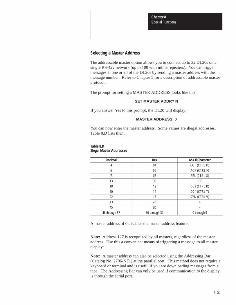
Chapter 8Special Functions
8–21
Selecting a Master Address
The addressable master option allows you to connect up to 32 DL20s on asingle RS-422 network (up to 100 with inline repeaters). You can triggermessages at one or all of the DL20s by sending a master address with themessage number. Refer to Chapter 5 for a description of addressable masterprotocol.
The prompt for setting a MASTER ADDRESS looks like this:
SET MASTER ADDR? N
If you answer Yes to this prompt, the DL20 will display:
MASTER ADDRESS: 0
You can now enter the master address. Some values are illegal addresses,Table 8.D lists them:
Table 8.DIllegal Master Addresses
Decimal Hex ASCII Character
4 04 EOT (CTRL D)
6 06 ACK (CTRL F)
7 07 BEL (CTRL G)
13 0D CR
18 12 DC2 (CTRL R)
20 14 DC4 (CTRL T)
22 16 SYN (CTRL V)
43 2B +
45 2D -
48 through 57 30 through 39 0 through 9
A master address of 0 disables the master address feature.
Note: Address 127 is recognized by all masters, regardless of the masteraddress. Use this a convenient means of triggering a message to all masterdisplays.
Note: A master address can also be selected using the Addressing Bar(Catalog No. 2706-NF1) at the parallel port. This method does not require akeyboard or terminal and is useful if you are downloading messages from atape. The Addressing Bar can only be used if communication to the displayis through the serial port.

Chapter 8Special Functions
8–22
Enable Dynamic Chaining
The prompt for DYNAMIC CHAINING looks like this:
DYNAMIC CHAINING? N
When dynamic chaining is enabled and the DL20 powers up in the run mode,the DL20 can be controlled using special messages #2, #8, and #9. Up to 20messages may be repeatedly displayed. Chapter 5 provides a description ofhow to use dynamic chaining.
Turn Relay On When Batteries are Low
The prompt for setting the relay looks like this:
RELAY FLAGS BAT? N
If you answer Yes to this prompt, the relay will be energized whenever thebatteries are low and one of the following occurs:
• Special message #4 test battery is triggered in the run mode.
• Power is cycled or the DL20 is reset.
• Internal clock time is 1:01:01
Use the relay to control a remote battery low indicator such as a light.
Note: Batteries are not user-serviceable, the DL20 must be returned forservice.

Chapter 8Special Functions
8–23
Displaying Prompts on All Slaves
The prompt for selecting the echo function looks like this:
ECHO ALL TO SLAVE?
Answering Yes to this prompt allows you to view menu edit and specialfunction prompts on all slave DL10 displays.
!ATTENTION: Do not use the ECHO ALL TO SLAVES specialfunction when sending messages to a printer, tape recorder orcomputer.
Flagging Errors
The prompt for flagging errors looks like this:
FLAG ERRORS? N
Answering Yes to this prompt enables the flagging of triggering errors forvariable stack data and invalid message triggers. If you select this featureand the DL20 cannot locate new data for a message containing variable data,asterisks will be displayed in place of the variable. If FLAG ERRORS is notselected, random numbers will appear in place of the variable data.
If FLAG ERRORS is enabled and a non-existing message is triggered, thefollowing error message is displayed:
ILLEGAL MSG TRIGGER
The error message is displayed until a valid message trigger is received.
If FLAG ERRORS is not enabled, all invalid message triggers are ignored.

A–B 9Chapter
9–1
Installation and Maintenance
This chapter describes:
• How to install the DL20
• How to connect external devices
• Replacement fuses
Panel cutout dimensions to install a display are shown in Appendix D.Overall dimensions, optional flush mount dimensions and enclosuredimensions are also shown in Appendix D.
Use these steps to mount a DL20 in a custom panel, enclosure, or optionalBulletin 2706 enclosures (Cat. No. 2706-NE1 and 2706-NE2). Whenproperly installed, the display faceplate provides a NEMA Type 12/13 enclosure.
Mounting Procedure
1. Cut and drill the appropriate mounting holes according to the panel cutoutdimensions found in Appendix D.
!ATTENTION: Displays should not be installed in a panel untilall panel cutouts and holes are completed. Metal filings createdwhen cutting and drilling could enter ventilation holes on thedisplay and cause the display to fail.
Mounting hardware (nuts) behind the panel can be eliminated by drilling andtapping the six mounting holes in the panel. Number 10 mounting screws arerecommended.
2. Insert the display in the panel cutout and tighten the six faceplatemounting screws.
Chapter Objectives
Installation Dimensions
DL20 Installation

Chapter 9Installation and Maintenance
9–2
Wiring Procedures
Refer to Figure 9.1 for wiring terminal descriptions. The proceduresdescribed below and the wiring terminal diagram guides you through thewiring process.
1. Connect an 85-264 VAC, 47-63 Hz input voltage source to terminals 26,27, and 28 of the DL20. The voltage source must have 15 amp (max)short circuit protection.
!ATTENTION: Terminal 28 (E. GND) must be connected to areliable low impedance earth ground to protect the display fromelectrical noise. This ground connection will also protectpersonnel from electrical shock if the electronics short to theDL20 case.
Do not turn on power to the display until all other wiring to the serial orparallel ports is completed.
2. Connect communication lines from the host programmable controller orcomputer as well as peripheral equipment to the serial or parallel ports ofthe DL20. Refer to Figures 9.2 through 9.12.
!ATTENTION: The DL20 has simplex (single direction)communication only. Only use the DL20 for non-critical displayapplications. Simplex communication provides no ACK/NAK(duplex) verification that messages sent by the programmablecontroller or computer have been received and displayed.
The data format for the RS-232 and RS-422 ports is identical. It is veryimportant that the communication parameters of the DL20 and the connecteddevice are the same.
Baud rate: 300, 1200, or 9600Data length: 8 bits (including parity if any)Parity: odd, even, or noneStop bits: 1
Use terminal 9 on the DL20 (+12 VDC OUT) to tie RS-232 handshake lineshigh if necessary. Do not use terminal 9 for any other purpose.

Chapter 9Installation and Maintenance
9–3
DL20 Wiring Terminals
Figure 9.1DL20 Connection Terminals
KY BD 1 2 3 4 5 6 7 8 9 10 11
RS422
-
RS 232OUT
+12VDCOUT
ETS -
ETS +
E.GND
RELAY SERIAL COMM PORT PARALLEL INPUT PORT AC PWR
MS1 MS0
+5 VDC OUT GND
VACHOT NEU
RELAY
KYBD
SERIAL COMM PORT PARALLEL INPUT PORT AC PWR
D9-D0 +5VDC OUTETS
11A 11B 12 13 14 15 16 17 18 19
GNDMS0 MS1
D9 D8 D7 D6 D5 D4 D3 D2 D1 D0N.C. COM N.O.
RS422
+
RS 232 IN GND
RELAY(Terminals 1, 2, and 3). Relay is switched whenever specified messages aredisplayed. It can be used, for example, to sound a horn and alert an operatorto read the display. The relay contacts are rated for 3 Amperes at 250 VACor 30 VDC.
KYBDThis input connector connects optional keyboards (Catalog No. 2706-NK1,-NK2).
Important: Only the 2706 keyboards may be plugged into this port. Allother programming keyboards must be connected to the SERIAL COMMPORT.
SERIAL COMM PORT(Terminals 4 thru 9). The DL20 is capable of two communication protocolson the SERIAL COMM PORT.
• RS-422 interface on terminals 4 and 5 is typically used to send data toremote displays or a printer. These devices may be up to 4,000 feet away.
• RS-232 output (terminal 6) can be connected to a printer. RS-232 input(terminal 7) can be used to program the DL20 or trigger messages. TheGND connection (terminal 8) doubles as an RS-232 common and a shieldground. The +12 VDC (terminal 9) is for tying RS-232 handshake lineshigh. DO NOT USE for any other purpose.
Data recorders, for storing messages on tape, are also connected to theRS-232 port.

Chapter 9Installation and Maintenance
9–4
PARALLEL INPUT PORT(Terminals 10 thru 23). The parallel input port accepts both commands andvariable data. Refer to Chapter 6 for more information.
MS1 MS0(Terminals 20 and 21). These lines indicate whether the data on the inputlines is a message number or variable data.
ETS(Terminals 10 and 11). The DL20 can be interfaced to multiplexed wordoutput modules via this input. When programmed properly, an edge orvoltage transition on this input causes data on the other parallel inputterminals to be read by the DL20. Note: For use with non Allen-Bradley programmable controllers.
D9-D0(Terminals 11A thru 19). Binary or BCD data on these lines is interpretedeither as a message number or as variable data.
+5VDC OUT(Terminal 22). Use to apply an ON voltage to any of the parallel input signalterminals (terminals 11A thru 21). Also use with Parallel Input Converters(Catalog No. 2706-NG1, -NG2).
Important: Do not use for any other purpose.
GND(Terminal 23.) Doubles as both a common reference for terminals 11A thru22 and a shield ground.
AC PWR(Terminal 26 thru 28.) The DL20 requires 85-264 VAC, 47-63 Hz. Theterminal marked E GND (terminal 28) must be connected to a reliable, lowimpedance earth ground.
Note: The DL20 uses low voltage signaling on both the parallel and theserial inputs. Any low voltage signals in a control panel are particularlynoise susceptible. Although the DL20 contains circuitry to filter noise,reasonable precautions are necessary to ensure proper operation of the DL20.The earth ground terminal (28) of the DL20 must be tied to a good earthground. Data input lines should be routed away from high energy wiring,transformers, solenoids or coils, and devices known to generate largeamounts of EMI or RFI. Transient noise suppressors across solenoids, andcoils are often helpful in reducing interference.
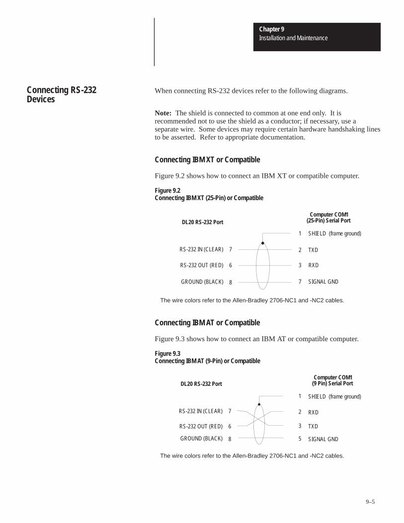
Chapter 9Installation and Maintenance
9–5
When connecting RS-232 devices refer to the following diagrams.
Note: The shield is connected to common at one end only. It isrecommended not to use the shield as a conductor; if necessary, use aseparate wire. Some devices may require certain hardware handshaking linesto be asserted. Refer to appropriate documentation.
Connecting IBM XT or Compatible
Figure 9.2 shows how to connect an IBM XT or compatible computer.
Figure 9.2Connecting IBM XT (25-Pin) or Compatible
DL20 RS-232 Port
SHIELD (frame ground)
TXD
RXD
SIGNAL GND
1
2
3
7
Computer COM1(25-Pin) Serial Port
The wire colors refer to the Allen-Bradley 2706-NC1 and -NC2 cables.
RS-232 IN (CLEAR)
RS-232 OUT (RED)
GROUND (BLACK)
7
6
8
Connecting IBM AT or Compatible
Figure 9.3 shows how to connect an IBM AT or compatible computer.
Figure 9.3Connecting IBM AT (9-Pin) or Compatible
DL20 RS-232 Port
SHIELD (frame ground)
RXD
TXD
SIGNAL GND
RS-232 IN (CLEAR)
RS-232 OUT (RED)
GROUND (BLACK)
1
2
3
5
Computer COM1(9 Pin) Serial Port
The wire colors refer to the Allen-Bradley 2706-NC1 and -NC2 cables.
7
6
8
Connecting RS-232Devices
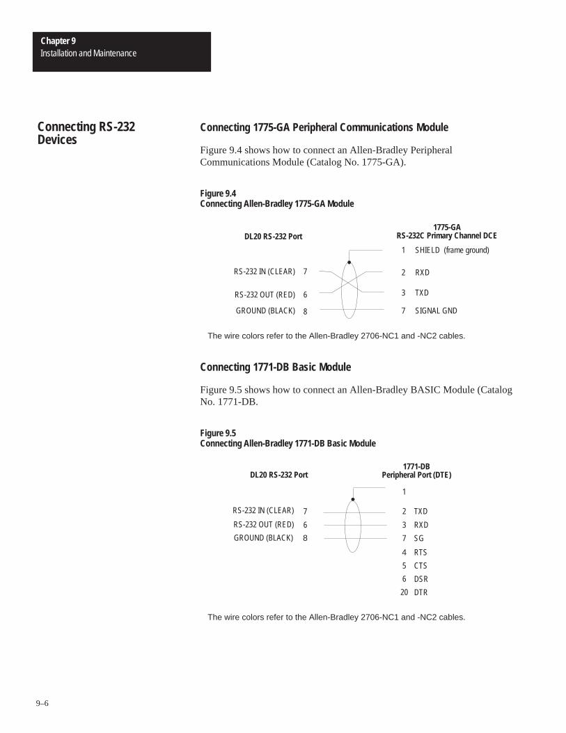
Chapter 9Installation and Maintenance
9–6
Connecting 1775-GA Peripheral Communications Module
Figure 9.4 shows how to connect an Allen-Bradley PeripheralCommunications Module (Catalog No. 1775-GA).
Figure 9.4Connecting Allen-Bradley 1775-GA Module
DL20 RS-232 Port
SHIELD (frame ground)
RXD
TXD
SIGNAL GND
RS-232 IN (CLEAR)
RS-232 OUT (RED)
GROUND (BLACK)
1
2
3
7
1775-GARS-232C Primary Channel DCE
The wire colors refer to the Allen-Bradley 2706-NC1 and -NC2 cables.
7
6
8
Connecting 1771-DB Basic Module
Figure 9.5 shows how to connect an Allen-Bradley BASIC Module (CatalogNo. 1771-DB.
Figure 9.5Connecting Allen-Bradley 1771-DB Basic Module
TXD
RXD
SG
1
2
3
7
1771-DBPeripheral Port (DTE)
The wire colors refer to the Allen-Bradley 2706-NC1 and -NC2 cables.
7
6
8
RTS4
CTS5
DSR6
DTR20
DL20 RS-232 Port
RS-232 IN (CLEAR)
RS-232 OUT (RED)
GROUND (BLACK)
Connecting RS-232Devices
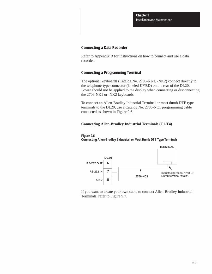
Chapter 9Installation and Maintenance
9–7
Connecting a Data Recorder
Refer to Appendix B for instructions on how to connect and use a datarecorder.
Connecting a Programming Terminal
The optional keyboards (Catalog No. 2706-NK1, -NK2) connect directly tothe telephone-type connector (labeled KYBD) on the rear of the DL20.Power should not be applied to the display when connecting or disconnectingthe 2706-NK1 or -NK2 keyboards.
To connect an Allen-Bradley Industrial Terminal or most dumb DTE typeterminals to the DL20, use a Catalog No. 2706-NC1 programming cableconnected as shown in Figure 9.6.
Connecting Allen-Bradley Industrial Terminals (T1-T4)
Figure 9.6Connecting Allen-Bradley Industrial or Most Dumb DTE Type Terminals
GND
RS-232 IN
RS-232 OUT 6
7
82706-NC1
Industrial terminal “Port B”.Dumb terminal “Main”.
DL20
TERMINAL
If you want to create your own cable to connect Allen-Bradley IndustrialTerminals, refer to Figure 9.7.

Chapter 9Installation and Maintenance
9–8
Figure 9.7Cable Diagram (Catalog No. 2706-NC1)
DL20 Display
SG
RD
TD
DL20 Display to Allen-Bradley Industrial Terminal (T1 thru T4)(Catalog No. 2706-NC1)
2
3
7
1
25
18
RS 232 IN
RS 232 OUT
GND
7
6
8
DEC VT Terminals
To connect a DEC VT Series Terminal to the DL20 use a Catalog No.2706-NC2 programming cable connected as shown in Figure 9.8.
Figure 9.8Connecting DEC VT Series Terminals
GND
RS-232 IN
RS-232 OUT 6
7
8 2706-NC2
”Main”
DEC TERMINAL
DL20
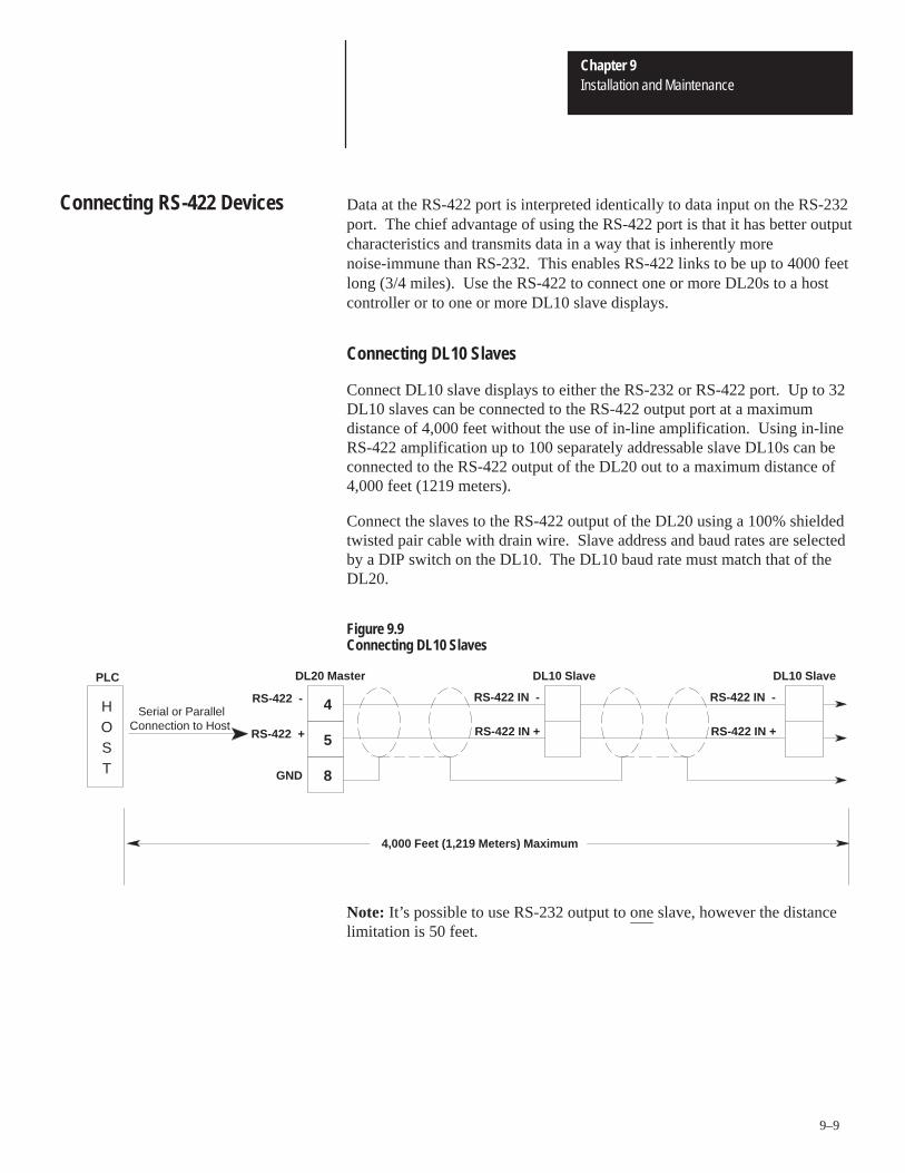
Chapter 9Installation and Maintenance
9–9
Data at the RS-422 port is interpreted identically to data input on the RS-232port. The chief advantage of using the RS-422 port is that it has better outputcharacteristics and transmits data in a way that is inherently morenoise-immune than RS-232. This enables RS-422 links to be up to 4000 feetlong (3/4 miles). Use the RS-422 to connect one or more DL20s to a hostcontroller or to one or more DL10 slave displays.
Connecting DL10 Slaves
Connect DL10 slave displays to either the RS-232 or RS-422 port. Up to 32DL10 slaves can be connected to the RS-422 output port at a maximumdistance of 4,000 feet without the use of in-line amplification. Using in-lineRS-422 amplification up to 100 separately addressable slave DL10s can beconnected to the RS-422 output of the DL20 out to a maximum distance of4,000 feet (1219 meters).
Connect the slaves to the RS-422 output of the DL20 using a 100% shieldedtwisted pair cable with drain wire. Slave address and baud rates are selectedby a DIP switch on the DL10. The DL10 baud rate must match that of theDL20.
Figure 9.9Connecting DL10 Slaves
RS-422 IN +
RS-422 IN -
RS-422 +
RS-422 -
RS-422 IN +
RS-422 IN -HOST
5
4
4,000 Feet (1,219 Meters) Maximum
GND 8
PLC DL20 Master DL10 Slave DL10 Slave
Serial or ParallelConnection to Host
Note: It’s possible to use RS-232 output to one slave, however the distancelimitation is 50 feet.
Connecting RS-422 Devices

Chapter 9Installation and Maintenance
9–10
Connecting Addressable DL20 Masters
Connect up to 32 individually addressable DL20s to an RS-422 port of aPLC or computer. The connection is made using a 100% shielded twistedpair cable with drain wire.
All DL20s must have their RS-422 port set for input, and their baud rates setidentically. Using in-line amplifiers, up to 100 addressable masters can beplaced on one RS-422 network up to 4,000 feet (1219 meters) in length.
Figure 9.10 illustrates how to connect addressable masters.
Figure 9.10Connecting Addressable DL20 Masters
GND
RS-422 IN -
RS-422 IN +RS-422 OUT +
RS-422 OUT - RS-422 IN -
RS-422 IN +
DL20DL20
Host PLC orcomputer serialRS-422 OUT
port.
5
4
5
4
4,000 Feet (1,219 Meters) Maximum

Chapter 9Installation and Maintenance
9–11
Connecting 1771-DB BASIC Module to a Single DL20
Figure 9.11 shows how to connect an Allen-Bradley BASIC Module(Catalog No. 1771-DB) to a single DL20.
Figure 9.11Connecting a DL20 to Allen-Bradley 1771-DB Basic Module
1771-DB RS-422Peripheral Port
GND
RS 422 (-)
RS 422 (+)
Chassis/Shield
RS-422 TXD
RS-422 TXD’
14
25
4
5
4
8
1
6
20
5
DL20 DisplayRS-422 Port
The RS-422 Port of the DL20 Display must be set for”Input” in the ”Set-Up I/O Ports” Menu when connected toa host as shown above.
Note: Other host controllers may usedifferent pin numbers than shown forthe 1771-DB.
Connecting 1771-DB BASIC Module to Multiple DL20s
Figure 9.12 shows how to connect an Allen-Bradley BASIC Module(Catalog No. 1771-DB) to multiple DL20s.
Figure 9.12Connecting DL20s to Allen-Bradley 1771-DB Basic Module
RS 422 (-)
RS 422 (+)
1771-DB RS-422Peripheral Port
Chassis/Shield
RS-422 TXD
RS-422 TXD’
5
6
20
4
25
1
14 5
4 RS 422 (-)
RS 422 (+)5
4
DL20 Display DL20 Display
Note: Other host controllers may usedifferent pin numbers than shown forthe 1771-DB.

Chapter 9Installation and Maintenance
9–12
If it is necessary to replace the internal fuse of the DL20, first remove powerto the display. Remove the fuse. Replacement fuses are listed below:
1.25A, 250 Volt AC, Type MDL1.5A, 250 Volt AC, Type GMC
Replacing Fuses

A–B 10Chapter
10–1
SpecificationsCharacter Height
1 Line Display 0.59 inches (15.1 mm). . . . . . . . . . . . . . . . . . . . . 2 Line Display: 0.44 inches (11.3 mm). . . . . . . . . . . . . . . . . . . . . 4 Line Display 0.49 inches (12.5 mm). . . . . . . . . . . . . . . . . . . . .
Character Set: Uppercase, lowercase, and symbols. . . . . . . . . . . . . .
Characters per Line: 20. . . . . . . . . . . . . . . . . . . . . . . . . . . . . . . . . .
Character Type: Vacuum fluorescent, dot matrix. . . . . . . . . . . . . . . . .
Approximate Viewing Distance1 Line Display: 30 feet (9.1 meters). . . . . . . . . . . . . . . . . . . . . . . 2 Line Display: 25 feet (7.6 meters). . . . . . . . . . . . . . . . . . . . . . . 4 Line Display: 25 feet (7.6 meters). . . . . . . . . . . . . . . . . . . . . . .
Input Power:4 Line Display 85-264 VAC, 45 VA max at 85 VAC. . . . . . . . . . . . 1 & 2 Line Display 85-264 VAC, 30 VA max at 85 VAC. . . . . . . . .
Fuse Type: 1.25A, 250 VAC, Type MDL. . . . . . . . . . . . . . . . . . . . . . . 1.5A, 250 VAC, Type GMC
Typical Input Resistance: 10K�. . . . . . . . . . . . . . . . . . . . . . . . . . . . 2.4 mA/Terminal @ 24VDC
Voltage Range: 5 to 30 VDC. . . . . . . . . . . . . . . . . . . . . . . . . . . . . . . 110/120 VAC using Input Converter
Logic Levels (High True Logic)0 or OFF 0 to 1.5 VDC. . . . . . . . . . . . . . . . . . . . . . . . . . . . . . . . Indeterminate 1.5 to 3.5 VDC. . . . . . . . . . . . . . . . . . . . . . . . . . . . 1 or ON 3.5 to 30 VDC. . . . . . . . . . . . . . . . . . . . . . . . . . . . . . . .
Terminals 10 data input / 2 strobe inputs. . . . . . . . . . . . . . . . . . . . . .
+5 VDC Out 15 mA maximum. . . . . . . . . . . . . . . . . . . . . . . . . . . . .
Logic Levels (Low True Logic)0 or OFF 0 to 1.5 VDC. . . . . . . . . . . . . . . . . . . . . . . . . . . . . . . . Indeterminate 1.5 to 4.0 VDC. . . . . . . . . . . . . . . . . . . . . . . . . . . . 1 or ON 4.0 to 15.0 VDC. . . . . . . . . . . . . . . . . . . . . . . . . . . . . . .
Standards RS-232 / RS-422. . . . . . . . . . . . . . . . . . . . . . . . . . . . . . . Baud Rate 300 / 1200 / 9600. . . . . . . . . . . . . . . . . . . . . . . . . . . . Parity (send only) Odd / Even / None. . . . . . . . . . . . . . . . . . . . . . Data Length 7 data bits (+ parity). . . . . . . . . . . . . . . . . . . . . . . . .
8 data bits (no parity)+12 V Output 3 mA maximum. . . . . . . . . . . . . . . . . . . . . . . . . . .
Display
Input Power
Parallel Port
ETS Input
Serial Port
Chapter 10Specifications
10–2
Operating Temperature: 32 to 140�F (0 to 60�C). . . . . . . . . . . . . . . . Storage Temperature: -40 to 185�F (-40 to 85�C). . . . . . . . . . . . . . . Humidity Rating: 5 to 95% (no condensation). . . . . . . . . . . . . . . . . . . NEMA Rating: UL Listed for Type 12/13 and designed . . . . . . . . . . . .
but not UL Listed for Type 4Shipping Weights
1 Line Display 9.5 pounds (4.32 kg). . . . . . . . . . . . . . . . . . . . . . . 2 Line Display 9.5 pounds (4.32 kg). . . . . . . . . . . . . . . . . . . . . . . 4 Line Display 12 pounds (5.4 kg). . . . . . . . . . . . . . . . . . . . . . . .
Environmental

A–B AAppendix
A–1
ASCII Character Set
\
DEL

A–B BAppendix
B–1
Tape Recorder Setup
This appendix describes how to upload and download messages using a datarecorder in various configurations including:
• Allen-Bradley Data Recorder (Catalog No. 1770-SB) with keyboard (Catalog No. 2706-NK1 or -NK2)
• Allen-Bradley Data Recorder (Catalog No. 1770-SB) with Allen-Bradley Industrial Terminal
• Allen-Bradley Data Recorder (Catalog No. 1770-SA) with keyboard (Catalog No. 2706-NK1 or -NK2)
• Allen-Bradley Data Recorder (Catalog No. 1770-SA) with Allen-Bradley Industrial Terminal
• EPI STR-LINK II or III with a dumb terminal.
Overview

Appendix BTape Recorder Setup
B–2
Refer to Figure B.1 when using a 1770-SB Data Recorder with optionalkeyboard (Catalog No. 2706-NK1 or -NK2).
Figure B.1Data Recorder (Catalog No. 1770-SB) with Keyboard (2706-NK1 or -NK2)
1770-SB RECORDER
DL20 DISPLAY
RS232OUT
6 7 8
RS232IN
GND Cable (Catalog No. 2706-NC4)
1. Connect the 2706-NC4 cable to terminals 6,7 and 8 of the DL20 asshown. DO NOT plug the cable into the 1770-SB at this time. Set toggleswitch on cable connector to the OFF or middle position.
2. Set baud rate of 1770-SB and the DL20 to 1200.
Note: For the new baud rate to be in effect at the DL20, the power must becycled, or the DL20 must be reset. Also, the keyboard baud rate must matchthe DL20 selection. (See DIP switch settings, Appendix E.)
Important: ECHO ALL TO SLAVES under the special functions must beOFF for Tape Operations to work properly.
3. Set Track Select of the 1770-SB to CONT.
4. Select USE AB 1770-SB in the Tape Operations special function.
1770-SB Data RecorderUsing a Keyboard

Appendix BTape Recorder Setup
B–3
5. Select desired function: WRITE TO TAPE, READ FROM TAPE orVERIFY TAPE.
6. Follow the instructions provided by the DL20. The following is anexample of WRITE TO TAPE.
DL20 Prompt Action Required
WRITE TO TAPE? Type [Y] [Return] on the keyboard.
HIT STOP/REWIND Press Stop/Rewind on the data recorder and wait for the tapeto rewind.
PLUG IN 1770-SB Plug the cable (Catalog No. 2706-NC4) into theCONTROLLER EQUIPMENT port on the data recorder.
PRESS RECORD ON TAPE Press Record on Tape button on the data recorder.
PUT TOGGLE ON RECORD Put toggle switch on cable (Catalog No. 2706-NC4) to theREC position.
TIME LEFT: 15(counts down to 1, then additional 10
second delay)
Wait until timer counts down or press [Esc]. An additional 10second pause occurs.
ADDR:(counts up as data is output)
Wait while data is being transferred.
PUT TOGGLE ON OFF Put toggle switch on cable (Catalog No. 2706-NC4) to theOFF (middle) position.
HIT STOP / REWIND Press Stop/Rewind button on the data recorder.
UNPLUG 1770-SB Unplug the cable (2706-NC4) from the data recorder.
VERIFY TAPE? Answer [Y] and follow the prompts, press [N] to return to edit.

Appendix BTape Recorder Setup
B–4
Refer to Figure B.2 when using a 1770-SB Data Recorder with anAllen-Bradley Industrial Terminal or other dumb terminal.
Figure B.2Data Recorder (Catalog No. 1770-SB) with Industrial Terminal
DL20 DISPLAY
1770-SB RECORDER
PORT B
2706-NC4
2706-NC1
ALLEN-BRADLEYINDUSTRIALTERMINAL
1770-T1 THRU T4
RS232OUT
6 7 8RS232IN
GND
!ATTENTION: Do not plug in the data recorder end of the cable(Catalog No. 2706-NC4) until the Industrial Terminal cable isunplugged. If both cables are plugged in at the same time, theDL20 may be damaged.
1. Connect the 2706-NC4 cable to the DL20 as shown. Do not connect theother end of the 2706-NC4 Cable to the 1770-SB until the IndustrialTerminal is disconnected later in this procedure. Damage to the DL20could result. Set toggle switch on cable connector to OFF or middleposition.
2. Using the Industrial Terminal, set baud rate of 1770-SB and the DL20 to1200.
Note: For the new baud rate to take effect for the DL20, the power must becycled, or the DL20 must be reset. Also, the Industrial Terminal baud ratemust match the DL20 selection.
Note: ECHO ALL TO SLAVES under the special functions must be OFFfor Tape Operations to work properly.
3. Set Track Select of the 1770-SB to Track 1 or 2.
4. Using the Industrial Terminal, select USE AB 1770-SB under TapeOperations special function.
1770-SB Data RecorderUsing an Industrial Terminal

Appendix BTape Recorder Setup
B–5
5. Select the desired function: WRITE TO TAPE, READ FROM TAPE orVERIFY TAPE.
6. Follow the instructions given by the DL20. The following is an exampleof WRITE TO TAPE.
DL20 Prompt Action Required
WRITE TO TAPE? Type [Y] [Return] on the terminal.
UNPLUG TERMINAL Unplug the cable (2706-NC1) from the Industrial Terminal.
HIT STOP/REWIND Press Stop/Rewind on the data recorder and wait for the tapeto rewind.
PLUG IN 1770-SB Plug the cable (Catalog No. 2706-NC4) into theCONTROLLER EQUIPMENT port on the data recorder.
PRESS RECORD ON TAPE Press Record on Tape button on the data recorder.
PUT TOGGLE ON RECORD Put toggle switch on cable (Catalog No. 2706-NC4) to theREC position.
TIME LEFT: 15(counts down to 1, then additional 10
second delay)
Wait until timer counts down. An additional 10 second pausewill occurs.
ADDR:(counts up as data is output)
Wait while data is being transferred.
PUT TOGGLE ON OFF Put toggle switch on cable (Catalog No. 2706-NC4) to theOFF (middle) position.
HIT STOP / REWIND Press Stop/Rewind button on the data recorder.
UNPLUG 1770-SB Unplug the cable (2706-NC4) from the data recorder.
PLUG IN TERMINAL Reconnect the cable (Catalog No. 2706-NC1) to the IndustrialTerminal port B.
VERIFY TAPE? Answer [Y] and follow the prompts, press [N] to return to edit.

Appendix BTape Recorder Setup
B–6
Refer to Figure B.3 when using a 1770-SA Data Recorder with optionalkeyboards (Catalog No. 2706-NK1 or -NK2).
Figure B.3Data Recorder (Catalog No. 1770-SA) with Keyboard (2706-NK1 or -NK2)
RS232OUT
6 7 8RS232IN
GND
1770-SA RECORDER
DL20 DISPLAY
2706-NC4
1. Connect the 2706-NC4 cable to terminals 6, 7 and 8 of the DL20 asshown. DO NOT connect to the 1770-SA at this time. Set toggle switchon cable connect to the OFF or middle position.
2. Set baud rate of DL20 to 1200 baud.
Note: In order for the new baud rate to be in effect, the power must becycled at the DL20, or the DL20 must be reset. Also, the keyboard baud ratemust match the DL20 selection. (See DIP switch settings, Appendix E.)
Note: ECHO ALL TO SLAVES under the special functions must be OFFfor Tape Operations to work properly.
3. Using the 2706-NK1 or NK2 Keyboard, select USE A-B 1770-SB fromTape Operations special function.
4. Select desired function: WRITE TO TAPE, READ FROM TAPE orVERIFY TAPE.
5. Follow the instructions provided by the DL20.
1770-SA Data RecorderUsing a Keyboard
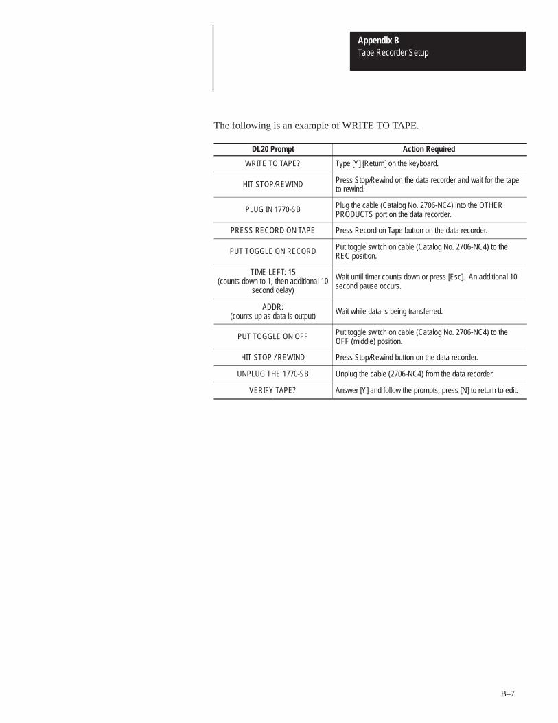
Appendix BTape Recorder Setup
B–7
The following is an example of WRITE TO TAPE.
DL20 Prompt Action Required
WRITE TO TAPE? Type [Y] [Return] on the keyboard.
HIT STOP/REWIND Press Stop/Rewind on the data recorder and wait for the tapeto rewind.
PLUG IN 1770-SB Plug the cable (Catalog No. 2706-NC4) into the OTHERPRODUCTS port on the data recorder.
PRESS RECORD ON TAPE Press Record on Tape button on the data recorder.
PUT TOGGLE ON RECORD Put toggle switch on cable (Catalog No. 2706-NC4) to theREC position.
TIME LEFT: 15(counts down to 1, then additional 10
second delay)
Wait until timer counts down or press [Esc]. An additional 10second pause occurs.
ADDR:(counts up as data is output)
Wait while data is being transferred.
PUT TOGGLE ON OFF Put toggle switch on cable (Catalog No. 2706-NC4) to theOFF (middle) position.
HIT STOP / REWIND Press Stop/Rewind button on the data recorder.
UNPLUG THE 1770-SB Unplug the cable (2706-NC4) from the data recorder.
VERIFY TAPE? Answer [Y] and follow the prompts, press [N] to return to edit.

Appendix BTape Recorder Setup
B–8
Refer to Figure B.4 when using a 1770-SA Data Recorder with anAllen-Bradley Industrial Terminal or other dumb terminal.
Figure B.4Data Recorder (Catalog No. 1770-SA) with Industrial Terminal
RS232OUT
6 7 8RS232IN
GND
DL20 DISPLAY
1770-SA RECORDER
PORT B
2706-NC4
2706-NC1
ALLEN-BRADLEYINDUSTRIALTERMINAL
1770-T1 THRU T4
RS232OUT
6 7 8RS232IN
GND
!ATTENTION: Do not plug in the data recorder end of the cable(Catalog No. 2706-NC4) until the Industrial Terminal Cable isunplugged. If both cables are plugged in at the same time, theDL20 may be damaged.
1. Connect the 2706-NC4 cable to the DL20, as shown. Do not connect theother end of the 2706-NC4 Cable to the 1770-SA until the IndustrialTerminal is disconnected later in this procedure. Damage to the DL20could result. Set toggle switch on cable to the OFF (middle) position.
2. Set baud rate of DL20 to 1200 Baud.
Note: In order for the new baud rate to be in effect, the power must becycled at the DL20, or the DL20 must be reset. Also, the Industrial Terminalbaud rate must match the DL20 selection.
Note: ECHO ALL TO SLAVES under the special functions must be OFFfor Tape Operations to work properly.
3. Using the industrial terminal, select Tape Operations special function.
4. Select USE AB 1770-SB from Tape Operations menu.
5. Select the desired function: WRITE TO TAPE, READ FROM TAPE orVERIFY TAPE.
6. Follow the instructions given by the DL20.
1770-SA Data RecorderUsing an Industrial Terminal

Appendix BTape Recorder Setup
B–9
The following is an example of WRITE TO TAPE.
DL20 Prompt Action Required
WRITE TO TAPE? Type [Y] [Return] on the terminal.
UNPLUG TERMINAL Unplug the cable (2706-NC1) from the Industrial Terminal.
HIT STOP/REWIND Press Stop/Rewind on the data recorder and wait for the tapeto rewind.
PLUG IN 1770-SB Plug the cable (Catalog No. 2706-NC4) into the OTHERPRODUCTS port on the data recorder.
PRESS RECORD ON TAPE Press Record on Tape button on the data recorder.
PUT TOGGLE ON RECORD Put toggle switch on cable (Catalog No. 2706-NC4) to theREC position.
TIME LEFT: 15(counts down to 1, then additional 10
second delay)
Wait until timer counts down. An additional 10 second pauseoccurs.
ADDR:(counts up as data is output)
Wait while data is being transferred.
PUT TOGGLE ON OFF Put toggle switch on cable (Catalog No. 2706-NC4) to theOFF (middle) position.
HIT STOP / REWIND Press Stop/Rewind button on the data recorder.
UNPLUG 1770-SB Unplug the cable (2706-NC4) from the data recorder.
PLUG IN TERMINAL Reconnect the cable (Catalog No. 2706-NC1) to the IndustrialTerminal port B.
VERIFY TAPE? Answer [Y] and follow the prompts, press [N] to return to edit.

Appendix BTape Recorder Setup
B–10
The EPI STR-LINK Recorders can be used as as storage device for DL20messages. There are DIP switches inside the STR-LINK II and III whichconfigure its operation. Refer to the user manual for the data recorder toaccess DIP switches. The DIP switches must be set as follows:
STR-LINK II Switch Settings
I/O Board DIP SwitchSwitch 1 OpenSwitch 2 OpenSwitch 3 OpenSwitch 4 Closed
Tape Interface Board DIP SwitchSwitch 1 OpenSwitch 2 ClosedSwitch 3 OpenSwitch 4 OpenSwitch 5 OpenSwitch 6 ClosedSwitch 7 Closed
The front panel switches must be set as follows:
Baud Rate 1200I/O Select RS-232Stop Bits 1Mode Select Full Duplex
STR-LINK III Switch Settings
10 Position DIP SwitchSwitch 1 LeftSwitch 2 LeftSwitch 3 LeftSwitch 4 RightSwitch 5 LeftSwitch 6 RightSwitch 7 RightSwitch 8 RightSwitch 9 LeftSwitch 10 Right
The front panel switches must be set as follows:
Track Select BothBaud Rate 1200
EPI STR-LINK Data Recorders

Appendix BTape Recorder Setup
B–11
DL20 Configuration
Make sure that the DL20 is set for:
Baud Rate = 1200Parity = None
Connecting EPI STR-LINK Recorders
Figure B.5 illustrates the connections. Connect the STR-LINK Recorder(DATA SET INTERFACE connector) to the DL20 RS-232 port using theTape Loader Cable (Catalog No. 2706-NC3) as shown.
If you are using a keyboard (Catalog No. 2706-NK1 or -NK2), plug thekeyboard into the rear of the DL20. No other connections are required.
If you are using an Allen-Bradley Industrial Terminal (T1 through T4), usecable (Catalog No. 2706-NC5). This cable connects to the DATATERMINAL INTERFACE connector on the data recorder and Port B on theindustrial terminal.
If you are using another type of dumb terminal, you must construct your owncable.
Figure B.5EPI STR-LINK Data Recorder
RS232OUT
6 7 8
RS232IN
GND
EPI STR-LINK RECORDER
DL20 DISPLAY
2706-NC3Tape Loader Cable
MAIN
DUMB TERMINAL
User Supplied Cable
Operating Procedures
The DL20 prompts you through the procedure. If necessary, refer to theprevious Allen-Bradley Data Recorder procedures for examples.

A–B CAppendix
C–1
Creating EPROM Files
This section describes how to transfer an application to a personal computerin an EPROM file format. Refer to Chapter 8, Special Functions, for theBURN PROM menu description.
The BURN PROM function converts the application to a Motorola hex fileformat that can be used to burn an EPROM. The file is transferred to a hostPersonal Computer (PC). Once stored in the PC, the file can be downloadedto an EPROM Programmer.
The file can be transferred to the PC using the WINDOWs programTERMINAL.exe or any other type of serial file transfer program.
Note: This appendix describes how to transfer files using the WINDOWSprogram TERMINAL.exe. If you are using a different type of transferprogram, you may see different prompting.
Refer to the following when transferring an application file to an EPROMprogrammer.
1. Connect a keyboard (Catalog No. 2707-NK1 or -NK2) to the DL20.Make sure that the baud rate of the keyboard and DL20 are the same.
2. Connect your PC to the DL20 RS-232 port as described in Chapter 9.
3. Enter the BURN PROM function of the DL20 as described in Chapter 8. Refer to the following sequence. When HIT CR WHEN READY isdisplayed, proceed to the next step.
���� ���
�
��� �� �������
�
�� �� ���� �����
Overview
File Transfer Programs
File Conversion

Appendix CCreating EPROM FIles
C–2
4. Set your PC to receive the file by running the program TERMINAL.exe.
5. In the TERMINAL Window, select Settings �Text Transfers andenter the following parameters:
Standard Flow Control (Xon/Xoff)No Word Wrap

Appendix CCreating EPROM Files
C–3
6. In the TERMINAL Window, select Settings �Communicationsand enter the following parameters:
Baud Rate, Parity, and Data Bits to match DL20Stop Bit = 1Flow Control = Xon/XoffNo Parity Check and No Carrier Detect SelectedConnector = port connected to DL20
Note: If possible, set the PC communications for COM2, allocating COM1for the mouse.
7. In the TERMINAL Window, select Transfers �Receive Text Fileand enter the file name that will contain the hex file for burning theEPROM, i.e. U EPROM.H.
Note: Don’t exit TERMINAL.exe.
8. At the DL20 keyboard, send the file by pressing [ENTER]. The timerwill start a countdown beginning at 15. At the end of the countdown, thefile is transferred.
9. When the DL20 has finished sending the file, select Stop on the bottombar of the terminal window.
10.The file is now in a Motorola hex format that can be used to program an xx ’128 EPROM.

Appendix CCreating EPROM FIles
C–4
To insert a programmed EPROM into the DL20:
!ATTENTION: Disconnect all power from the DL20 beforeremoving the cover. Failure to do so may result in electricalshock or damage to the DL20.
!ATTENTION: Make sure you are properly grounded to preventdamage from Electrostatic Discharge (ESD). An ESD groundingstrap is recommended. Failure to do so may result in damage tothe DL20 circuit board.
Important: An EPROM can only be programmed and inserted into a DL20display having 16K bytes or less of messages programmed into RAM.
1. Loosen the three cover screws and lift the top cover off the DL20.
2. Insert the EPROM into the socket designated IC18. See Figure C.1. Pin #1 of the EPROM should be in the upper left corner of the socket asyou face the front of the DL20.
Figure C.1Message EPROM Socket
FRONT OF DL20
Display Tube
MESSAGEEPROMSOCKET
IC15
IC16
IC14
IC17 IC18 IC20 IC21
Pin #1
MAIN CIRCUIT BOARD
3. Replace the cover and tighten screws to a torque of 10 inch/lbs.
Inserting the EPROM

A–B DAppendix
D–1
Dimensions
This appendix provides the approximate dimensions for DL20s.
Figure D.1 provides the dimensions for the panel cut out.
Figure D.1Panel Cut Out Dimensions
13.62 (345.9 mm)Cut Out
6.94(176.1mm)
5.30(134.6 mm)
Cut Out
5.68(144.3 mm)
0.25 (6.4 mm)DIA. HOLE (6 PLACES)NOTE: HOLES MAY BE
DRILLED SMALLER ANDTAPPED FOR NO. 10
HARDWARE.
3.88(98.4 mm)
0.13(3.1 mm)
0.19(4.8 mm)
13.87(352.3 mm)
3.50(88.9 mm)
Cut Out
0.25 (6.4 mm)DIA. HOLE (6 PLACES)NOTE: HOLES MAY BEDRILLED SMALLER AND
TAPPED FOR NO. 10HARDWARE.
6.94 (176.1mm)
13.87(352.3 mm)
6.81 (173.0 mm)
0.19(4.8 mm)
Four Line DL20 Display
13.62 (345.9 mm)Cut Out
One and Two Line DL20 Displays
Overview
Panel Cutout Dimensions

Appendix DDimensions
D–2
Figure D.2 provides the overall dimensions of the one and two line DL20.
Figure D.2One and Two Line DL20 Dimensions
6.65(168.9 mm)
DIM. ”A’’SEE
CHART
0.12 TYP.(3.2 mm)
0.72(18.3 mm)13.30
(337.8 mm)
Top View
14.37(365.0 mm)
DIM. ‘‘B’’SEE CHART
4.38(111.2 mm)
Front View
0.125 (3.2 mm) (GASKET THICKNESS)
0.099 (2.5 mm)(PANEL THICKNESS)
Side View
0.62(15.7 mm)
3.13(79.5 mm)
0.62(15.7 mm)
SixMounting
Studs
7.37(187.2 mm)
Display Type Dimension A Dimension B
One Line
Two Line
1.25 inches(31.8 mm)
Dimensions Inches (Millimeters)
1.70 inches(43.2 mm)
10.12 inches(257.2 mm)8.81 inches(223.8 mm)
Overall Dimensions

Appendix DDimensions
D–3
Figure D.3 provides the overall dimensions of the four line DL20.
Figure D.3Four Line DL20 Dimensions
2.94 (74.7 mm)
1.63 (41.4 mm)
6.18(157.0 mm)
14.37 (365.0 mm)
Front View
Side View
0.099 (2.5 mm)(PANEL THICKNESS)
0.125 (3.2 mm)(GASKET THICKNESS)
7.37(187.2 mm) 0.53
(13.5 mm)
5.12(130.0 mm)
13.30(337.8 mm)
6.65(168.9 mm)
Top View
0.72(18.3 mm)
0.12 Typ.(3.0 mm)
SixMounting
Studs
0.53(13.5 mm)
8.83 (224.3 mm)
Dimensions Inches (Millimeters)
0.53(13.5 mm)

Appendix DDimensions
D–4
Figure D.4 provides the dimensions of the optional flush mount displays.
Figure D.4Flush Mount Panel Cut Out Dimensions
0.16
(4.1 mm)
1.80 (45.7 mm)
1.89 (48.0 mm)
Dimensions Inches (Millimeters)
12.42 (315.5 mm)
11.70 (297.2 mm)
2.59(65.8 mm)
8.83 (224.3 mm) Cut Out
2.94 (74.7 mm) Cut Out 3.34(84.8 mm)
12.42 (315.5 mm)
10.12 (257.2 mm) Cut Out
1.62 (41.2 mm) 1.89 (48.0 mm)1.25 (31.8 mm) Cut Out
0.281 DIA. (7.1 mm)
(FOR LED LENS)
0.187 DIA. (4.7 mm) 4 Holes
1.15 (29.2 mm)
1.62(41.2 mm)
1.80 (45.7 mm)
0.10(2.5 mm)
12.42 (315.5 mm)
11.70 (297.2 mm)
8.81 (223.8 mm) Cut Out
1.70 (43.2 mm) Cut Out
One LineFlush MountDisplay
Two LineFlush MountDisplay
Four LineFlush MountDisplay
0.13 (3.3 mm)
0.187 (4.7 mm) DIA.
4 Holes
0.281 DIA. (7.1 mm)
(FOR LED LENS)
0.187 (4.7 mm) DIA.
4 Holes
0.281 DIA. (7.1 mm)
(FOR LED LENS)
11.70 (297.2 mm)
Flush Mount PanelCutout Dimensions

Appendix DDimensions
D–5
Figure D.5 provides the dimensions of the panel mounted Parallel InputConverter. Figure D.6 shows the dimensions of the display mounted ParallelInput Converter.
!ATTENTION: Parallel Input Converters (Catalog No.2706–NG1, –NG2) cannot accept 220/240VAC. If 220/240VACis applied to the Parallel Input Converter, damage to the inputconverter will occur.
Figure D.5Panel Mounted Converter (Catalog No. 2706-NG2) Dimensions
0.75(19.1)
2.38(60.5)
FrontSide
7.88(200.2) 6.76
(171.5)
7.44(189.0) 1.25
(31.8)
3.56(90.4)
Parallel Input ConverterDimensions

Appendix DDimensions
D–6
Figure D.6Display Mounted Converter (Catalog No. 2706-NG1) Dimensions
6.76(171.5)
7.88(200.2)
Side
DL20
1.25(31.8)
3.56(90.4)
2.43(61.7)
1.37(34.0)
0.46(11.7)

Appendix DDimensions
D–7
Figure D.7 provides the dimensions of the optional enclosure.
Figure D.7Enclosure Dimensions
13.87 (352.3)
2706–NE1 3.87(98.3)
3.44(87.4)
6.31(160.3)
5.96(151.4)
A B C D
5.68(144.3)
5.25(133.4)
8.11(206)
7.77(197.4)
2706–NE2
D
8.20 (208.3)
C
0.50 (12.7 mm)
BCut Out
1.43(36.3)
15.88 (403.4)
1.29 (32.8)
D
1.05(26.7)
A
1.29(32.8)
13.61 (345.7)Cut Out
16.19 (411.2)
6–.25Dia. Holes
(6.4)
Dimensions Inches (Millimeters)
C
Front View
Right Side View
EnclosureDimensions
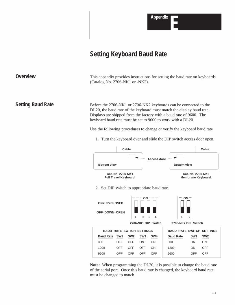
A–B EAppendix
E–1
Setting Keyboard Baud Rate
This appendix provides instructions for setting the baud rate on keyboards(Catalog No. 2706-NK1 or -NK2).
Before the 2706-NK1 or 2706-NK2 keyboards can be connected to theDL20, the baud rate of the keyboard must match the display baud rate.Displays are shipped from the factory with a baud rate of 9600. Thekeyboard baud rate must be set to 9600 to work with a DL20.
Use the following procedures to change or verify the keyboard baud rate
1. Turn the keyboard over and slide the DIP switch access door open.
Access door
CableCable
Bottom viewBottom view
Cat. No. 2706-NK1Full Travel Keyboard.
Cat. No. 2706-NK2Membrane Keyboard.
2. Set DIP switch to appropriate baud rate.
ON
2 3 41
ON=UP=CLOSED
OFF=DOWN=OPEN
BAUD RATE SWITCH SETTINGS
Baud Rate SW1 SW2 SW3 SW4
300 OFF OFF ON ON
1200 OFF OFF OFF ON
9600 OFF OFF OFF OFF
BAUD RATE SWITCH SETTINGS
Baud Rate SW1 SW2
300 ON ON
1200 ON OFF
9600 OFF OFF
ON
21
2706-NK1 DIP Switch 2706-NK2 DIP Switch
Note: When programming the DL20, it is possible to change the baud rateof the serial port. Once this baud rate is changed, the keyboard baud ratemust be changed to match.
Overview
Setting Baud Rate
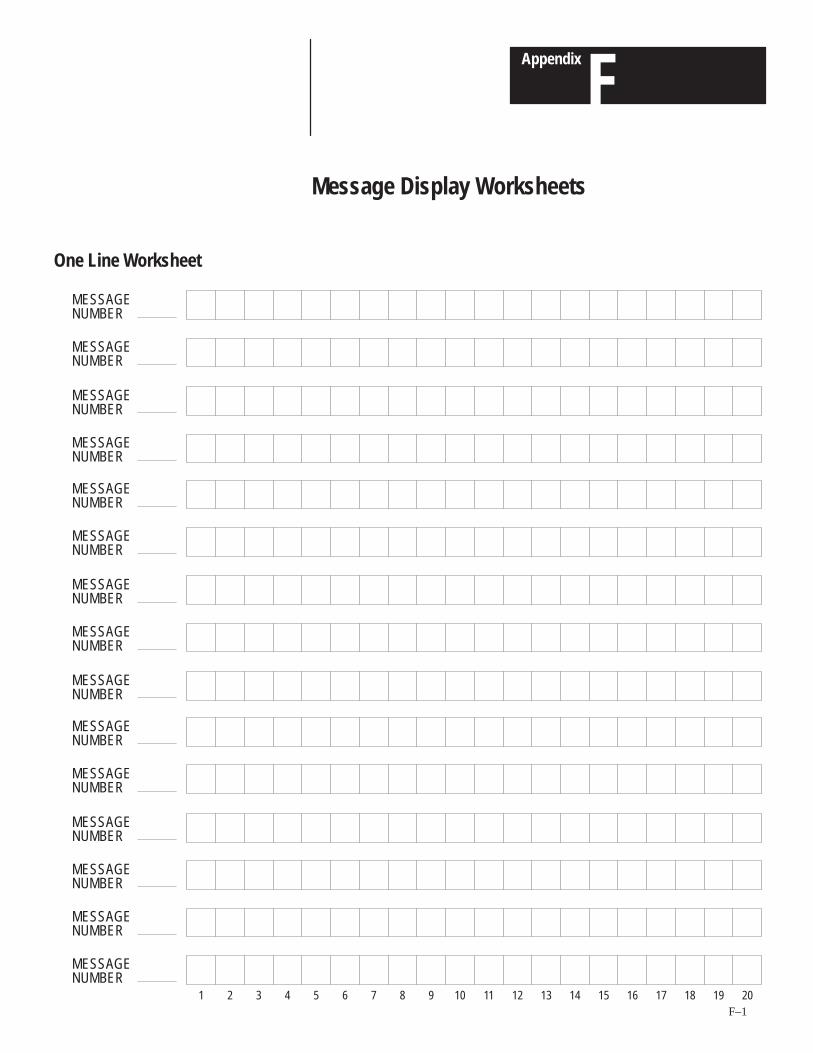
A–B FAppendix
F–1
Message Display Worksheets
MESSAGENUMBER
MESSAGENUMBER
MESSAGENUMBER
MESSAGENUMBER
MESSAGENUMBER
MESSAGENUMBER
MESSAGENUMBER
MESSAGENUMBER
MESSAGENUMBER
MESSAGENUMBER
MESSAGENUMBER
MESSAGENUMBER
MESSAGENUMBER
MESSAGENUMBER
MESSAGENUMBER
1 2 3 4 5 6 7 8 9 10 11 12 13 14 15 16 17 18 19 20
One Line Worksheet

Appendix FMessage Display Worksheets
F–2
MESSAGENUMBER
MESSAGENUMBER
MESSAGENUMBER
MESSAGENUMBER
MESSAGENUMBER
MESSAGENUMBER
MESSAGENUMBER
MESSAGENUMBER
MESSAGENUMBER
MESSAGENUMBER
MESSAGENUMBER
1 2 3 4 5 6 7 8 9 10 11 12 13 14 15 16 17 18 19 20
Two Line Worksheet
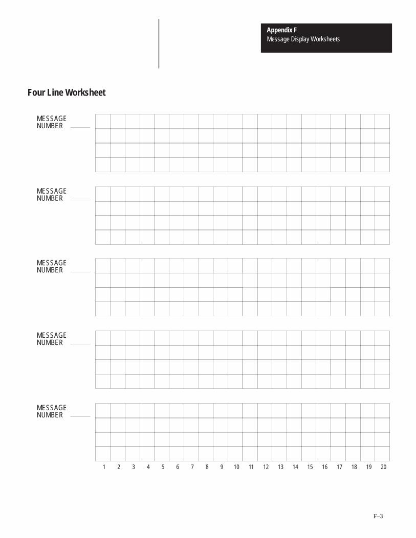
Appendix FMessage Display Worksheets
F–3
MESSAGENUMBER
MESSAGENUMBER
MESSAGENUMBER
MESSAGENUMBER
MESSAGENUMBER
1 2 3 4 5 6 7 8 9 10 11 12 13 14 15 16 17 18 19 20
Four Line Worksheet

A–B GAppendix
G–1
Application Notes
This appendix provides examples of interfacing a DL20 with PLC-2 andPLC-5 Programmable Controllers through the DL20 parallel port.Programming examples and connection diagrams show how to transfermessage triggers and variable data from 1771 I/O modules to the DL20parallel port.
The examples and diagrams used in this appendix are included solely forillustrative purposes.
!ATTENTION: The DL20 has single direction communicationand should be used only for non-critical display applications. Single direction communication does not provide verification thatmessages from the programmable controller have been receivedand displayed by the DL20.
The PLC-2 processor configuration for both examples is listed below. Thisconfiguration may vary for different applications.
1. A 1770-T3 Industrial Terminal is used.
2. The “SEARCH 50” command configures the data table for 1 data tableblock and 2 I/O racks. The Mini PLC-2/15 or Mini PLC-2/05 processorsautomatically default to the 2 I/O rack configuration.
3. The output modules (2) are in Rack 1, module group 0 (word address010).
4. The DL20 configuration is defined separately for each program example.
• high true logic
• BCD messages / variable data
• time driven
• DC inputs
• scan = 4, debounce = 1
Overview
PLC-2 Programming Examples

Appendix GApplication Notes
G–2
Triggering Simple Messages (PLC-2)
Figure G.1 illustrates how individual inputs can trigger correspondingmessages.
Figure G.1Triggering Messages Using Individual Inputs (PLC-2)
00
112
010
001
PUT
001
057
G Rung 1
060
020
G010
001
PUT Rung 2
01
112 061
021
G010
001
PUT Rung 3
02
112 062
022
G010
001
PUT Rung 4
If two or more inputs are true at the same time, the rung closest to the end ofthe ladder diagram has priority and only this message is triggered during theprogram scan.
When no inputs are true, the display clears since the 1st rung shown alwaystriggers special message #1 if none of the rungs after it are true. Specialmessage #1 clears the display. If your application requires that the lastmessage displayed remains displayed indefinitely, do not program the firstrung in this example. The DL20 Auto Clear message feature must bedisabled for this type of operation.
In this example, one rung is required for each unique message triggered.
The DL20 examines 10 bits (D0-D9) on the parallel port when a messagenumber is strobed in. If binary is selected, a range of message numbersfrom 1 to 1022 is allowed. If BCD is selected, a range of message numbersfrom 1 to 399 is allowed.
PLC-2 Programming Examples
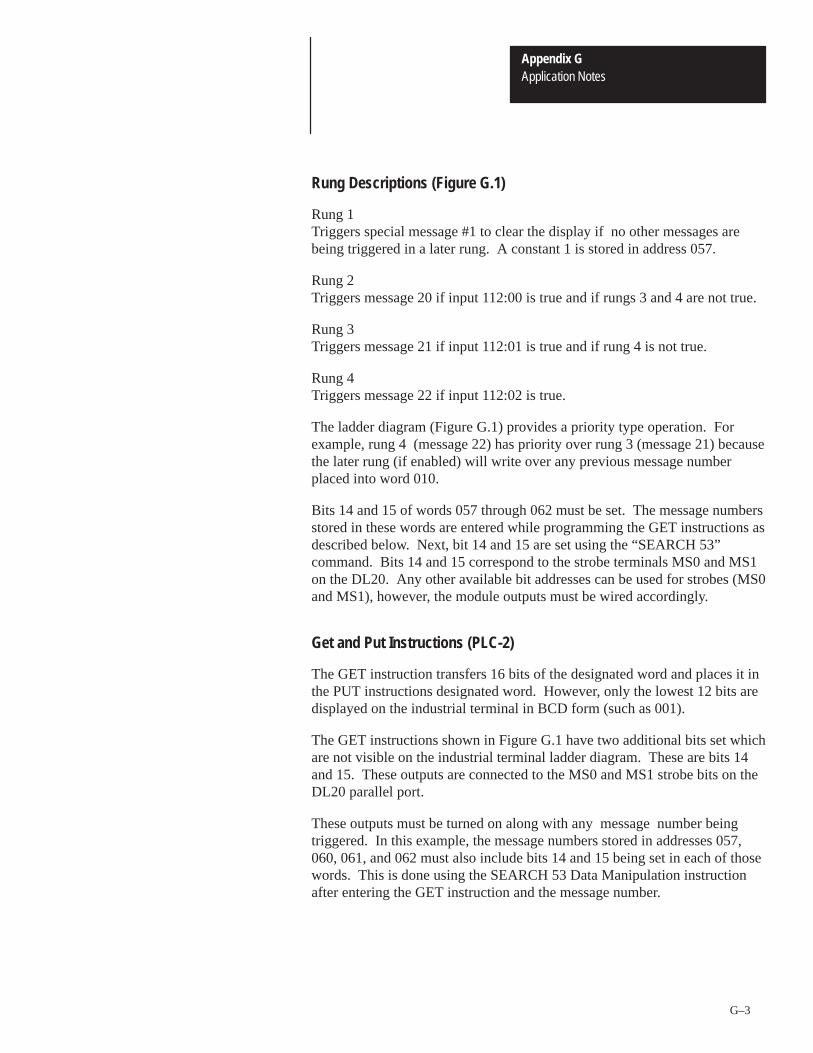
Appendix GApplication Notes
G–3
Rung Descriptions (Figure G.1)
Rung 1 Triggers special message #1 to clear the display if no other messages arebeing triggered in a later rung. A constant 1 is stored in address 057.
Rung 2 Triggers message 20 if input 112:00 is true and if rungs 3 and 4 are not true.
Rung 3 Triggers message 21 if input 112:01 is true and if rung 4 is not true.
Rung 4 Triggers message 22 if input 112:02 is true.
The ladder diagram (Figure G.1) provides a priority type operation. Forexample, rung 4 (message 22) has priority over rung 3 (message 21) becausethe later rung (if enabled) will write over any previous message numberplaced into word 010.
Bits 14 and 15 of words 057 through 062 must be set. The message numbersstored in these words are entered while programming the GET instructions asdescribed below. Next, bit 14 and 15 are set using the “SEARCH 53”command. Bits 14 and 15 correspond to the strobe terminals MS0 and MS1on the DL20. Any other available bit addresses can be used for strobes (MS0and MS1), however, the module outputs must be wired accordingly.
Get and Put Instructions (PLC-2)
The GET instruction transfers 16 bits of the designated word and places it inthe PUT instructions designated word. However, only the lowest 12 bits aredisplayed on the industrial terminal in BCD form (such as 001).
The GET instructions shown in Figure G.1 have two additional bits set whichare not visible on the industrial terminal ladder diagram. These are bits 14and 15. These outputs are connected to the MS0 and MS1 strobe bits on theDL20 parallel port.
These outputs must be turned on along with any message number beingtriggered. In this example, the message numbers stored in addresses 057,060, 061, and 062 must also include bits 14 and 15 being set in each of thosewords. This is done using the SEARCH 53 Data Manipulation instructionafter entering the GET instruction and the message number.
Appendix GApplication Notes
G–4
Triggering Messages with Variable Data (PLC-2)
This example illustrates how a message with a variable data value from aPLC-2 Programmable Controller can be displayed on a DL20.
There are 10 data lines (D0-D9) and 2 strobe lines (MS0 and MS1) on theDL20. If both MS0 and MS1 are high, it indicates to the DL20 that the valuepresent on the data lines D0-D9 is a message number to be triggered. At thispoint all 10 data lines (D0-D9) are examined. If binary message data isselected in the DL20 menu, the range is 1 to 1022. If BCD message data isselected, the range is 1 to 399.
The DL20 displays variable data from the programmable controller within arange of 0 to ±32, 767 binary or 0 to 9999 BCD. Because these are 16 bitdata values and the DL20 has only 10 data lines, each variable must bestrobed into the DL20 in two parts, 8 bits at a time. First the high byte isstrobed in. This is indicated by setting the strobe bit MS0 low and MS1high. Next the low byte (least significant data) is strobed in to the DL20.This is indicated by setting the strobe bit MS0 high and MS1 low.
When a message is created on the DL20 a variable data symbol ↑ or ↓ can beplaced anywhere, and up to twenty times, within a message by pressing the[Ctrl] key and [V] or [X] at the same time. For most keyboards (2706keyboards) the [Ctrl] key and [V ]or [X] must be pressed simultaneously.For the 1770-T3 Industrial Terminal, they must be pressed sequentially.Control V is for non-decimal point variables and control X is for decimalpoint variables and/or fixed format variables. The programmable controllermust sequentially strobe the variables into the DL20 data queue in the sameorder that the variables are to appear in the message. After the variables arequeued, then the message number is triggered.
The following program example uses a sequencer output instruction from thePLC-2 to strobe the information into the DL20 parallel port.
PLC-2 Programming Examples

Appendix GApplication Notes
G–5
Table G.APLC-2 Sequencer Outputs
PC Word Step BCDFormat
Binary Format Comments
037 1 3010 0011000000010000Special Message 10 (Clear
Queues)
040 2 0000 0000000000000000 Null Step
041 3 2012 0010000000010010Hi Data
(1st Variable)
042 4 0000 0000000000000000 Null Step
043 5 1034 0001000000110100Low Data
(1st Variable)
044 6 0000 0000000000000000 Null Step
045 7 3020 0011000000100000 Message Member
046 8 0000 0000000000000000 Null Step
The steps of a sequencer instruction can be viewed on the 1770-T3 IndustrialTerminal by moving the cursor to the sequencer instruction and pressing<Display> 1 for BCD display format or <Display> 0 for binary displayformat.
The NULL STEPS shown in the above sequence are added to satisfy timingrequirements of the DL20.
In the following program example, steps 1 through 8 shown above representword 037-046 (octal) as defined in the sequencer instruction.
The resulting message would be displayed:
TIMER 032 = 1234
The variable 1234 shown on the above display and in the example steps is forillustration purposes only. Actually, the free running timer 032 in the rungexamples to follow range from 0 to 999.

Appendix GApplication Notes
G–6
Figure G.2 shows the example ladder program for transferring variable datawith a PLC-2.
Figure G.2PLC-2 Ladder Program (Messages with Variable Data)
030
17EN Rung 1
031
.01PR 002AC 000
TON Rung 214
111
15
031
030
15DN
SEQUENCER OUTPUTCOUNTER ADDR: 030CURRENT STEP: 008SEQ LENGTH: 008WORDS PER STEP: 1FILE: 037-046MASK: 035-035OUTPUT WORDS1: 010 2:3: 4:
15
031
15
030
15
032 032
.01PR 999AC 000
TON Rung 3
012
030G
002
034= ZCL
00
032
00
043
01
032
01
043
02
032
02
043
03
032
03
043
04
032
04
043
05
032
05
043
Rung 4
Rung 5
Rung 6
Rung 7
Rung 8
Rung 9
Rung 10
PLC-2 Programming Examples

Appendix GApplication Notes
G–7
Figure G.2PLC-2 Ladder Program (Messages with Variable Data) Continued
ZCL
06
032
06
043Rung 11
07
032
07
043Rung 12
10
032
00
041Rung 13
11
032
01
041Rung 14
12
032
02
041Rung 15
13
032
03
041Rung 16
Rung 17
Rung Descriptions (Figure G.2)
Rung 1Each time TON 031 is done, the sequencer instruction outputs the next step.These steps were described previously. The sequencer done bit is set whenthe sequencer reaches its last step.
SEQ LENGTH: Number of steps (8 for this example).
WORDS PER STEP: 1 (for this example).
FILE: Address range of steps (037-046 for this example).
MASK: Select any available address and set all bits equal to 1 (035 forthis example).
OUTPUT WORD: I/O address at which the output modules for the DL20are located (010 for this example).
Appendix GApplication Notes
G–8
Rung 2This is the rung that actually triggers the message. Setting input address111:14 momentarily will initiate one complete sequence, displaying themessage with variable data. If the application requires the variables to becontinuously updated on the display, then, address 111:14 should be sethigh continuously for that period of time.
Timer 031 determines the time between step changes. This time shouldnot be set lower than 70 milliseconds per step for AC output moduleapplications using a Parallel Input Converter (2706-NG1, -NG2, Series A or B).
For DC output module applications the minimum timer value (031) is 20milliseconds (002 in the example). The DL20 scan time should be nearthe minimum value 4 and likewise the debounce time should be set nearits minimum, 1.
Rung 3A free-running timer is used to create the data value being displayed.
Rung 4 This rung and rung 17 assure that both the high byte and low byte dataportion of the variable are both moved to the appropriate word in thesequencer file at the same time. Otherwise, the timer value could changebetween the time that the high byte and low byte are strobed to the DL20.
The GET instruction (address 030) is the same address used for thesequencer instruction and contains the current “step number”. The equalinstruction (address 034) could have been any available address and muststore a constant (2 in this case), so that rungs 5-16 will only be scannedand updated once per sequencer cycle. Any step can be selected,however, step 2 is the last step prior to the variable data being sent to theDL20.
Rungs 5-12Transfer the low byte data from timer 032 accumulative value to theappropriate sequencer step (word 043).
Rungs 13-16 Transfer the high byte data from timer 032 accumulative value to theappropriate sequencer step (word 041).
Rung 17Marks the end of the zone to be controlled according to rung 4.
PLC-2 Programming Examples
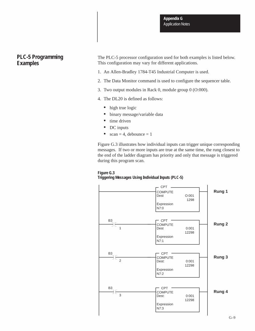
Appendix GApplication Notes
G–9
The PLC-5 processor configuration used for both examples is listed below.This configuration may vary for different applications.
1. An Allen-Bradley 1784-T45 Industrial Computer is used.
2. The Data Monitor command is used to configure the sequencer table.
3. Two output modules in Rack 0, module group 0 (O:000).
4. The DL20 is defined as follows:
• high true logic
• binary message/variable data
• time driven
• DC inputs
• scan = 4, debounce = 1
Figure G.3 illustrates how individual inputs can trigger unique correspondingmessages. If two or more inputs are true at the same time, the rung closest tothe end of the ladder diagram has priority and only that message is triggeredduring this program scan.
Figure G.3Triggering Messages Using Individual Inputs (PLC-5)
CPT
CPT
CPT
COMPUTEDest: 0:001
12298ExpressionN7:2
COMPUTEDest 0:001
12298ExpressionN7:1
COMPUTEDest O:001
1298ExpressionN7:0
Rung 1
Rung 2
Rung 3
Rung 4CPT
COMPUTEDest: 0:001
12298ExpressionN7:3
B3
1
B3
2
3
B3
PLC-5 ProgrammingExamples

Appendix GApplication Notes
G–10
When no inputs are true, the display clears since the 1st rung shown alwaystriggers special message #1. If your application requires that the lastmessage remains displayed indefinitely, do not program the first rung. The DL20 Auto Clear message feature must be disabled for this type ofoperation.
In this example, one rung is required for each unique message to betriggered.
The DL20 examines 10 bits (D0-D9) on the parallel port when a messagenumber is strobed in. If binary message data is selected, a range of uniquemessage numbers from 1 to 1022 is allowed. If BCD message data isselected, a range of unique message numbers from 1 to 399 is allowed.
Rung Descriptions (Figure G.3)
Rung 1 Triggers special message number 1 to clear the display if no othermessages are being triggered in a later rung. A constant 1 is stored inaddress N7:0.
Rung 2 Triggers message number 20 if input B3:1 is true and if rungs 3 and 4 arenot true.
Rung 3Triggers message number 21 if input B3:2 is true and if rung 4 is not true.
Rung 4 Triggers message number 22 if input B3:3 is true.
This example provides a priority type of operation. For example, rung 4(message 22) has priority over rung 3 (message 21) because the later rung (iftrue) will write over any previous message number put into output word0:000.
Compute Instruction
The CPT instruction will get all 16 bits of the designation source word andmove it into the designated destination word. This instruction may also besubstituted with a MOV (move) or MVM (move with mask) instruction.
PLC-5 ProgrammingExamples
Appendix GApplication Notes
G–11
Triggering Messages with Variable Data
This program example illustrates how a message with a variable data valuefrom a PLC-5 Programmable Controller can be displayed on a DL20.
There are 10 data lines (D0-D9) and 2 strobe lines MS0 and MS1 on theDL20. If both MS0 and MS1 are high, it indicates to the DL20 that the valuepresent on the data lines D0-D9 is a message number to be triggered. At thispoint, all 10 data lines (D0-D9) are examined. If binary message data isselected, then the range is 1 to 1022. If BCD message data is selected, thenthe range is 1 to 399.
The DL20 displays variable data from the programmable controller within arange of 0 to ±32, 767 binary or 0 to 9999 BCD. Because these are 16 bitdata values and the DL20 has only 10 data lines, each variable must bestrobed into the DL20 in two parts, 8 bits at a time. First the high byte isstrobed in. This is indicated by setting the strobe bit MS0 low and MS1high. Next the low byte (least significant data) is strobed in to the DL20.This is indicated by setting the strobe bit MS0 high and MS1 low.
When a message is created on the DL20 a variable data symbol ↑ or ↓ can beplaced anywhere and up to twenty times within a message by pressing the[Ctrl] key and [V] or [X] at the same time. For most keyboards (2706keyboards) the [Ctrl] key and [V] or [X] must be pressed simultaneously.For the 1770-T3 Industrial Terminal, they must be pressed sequentially.Control V is for non-decimal point variables and control X is for decimalpoint variables and or fixed format variables. The programmable controllermust sequentially strobe the variables into the DL20 data queue in the sameorder that the variables appear in the message. After the variables arequeued, the message number is triggered.
The following program example uses a sequencer output instruction from thePLC-5 to strobe the information into the DL20 parallel port.
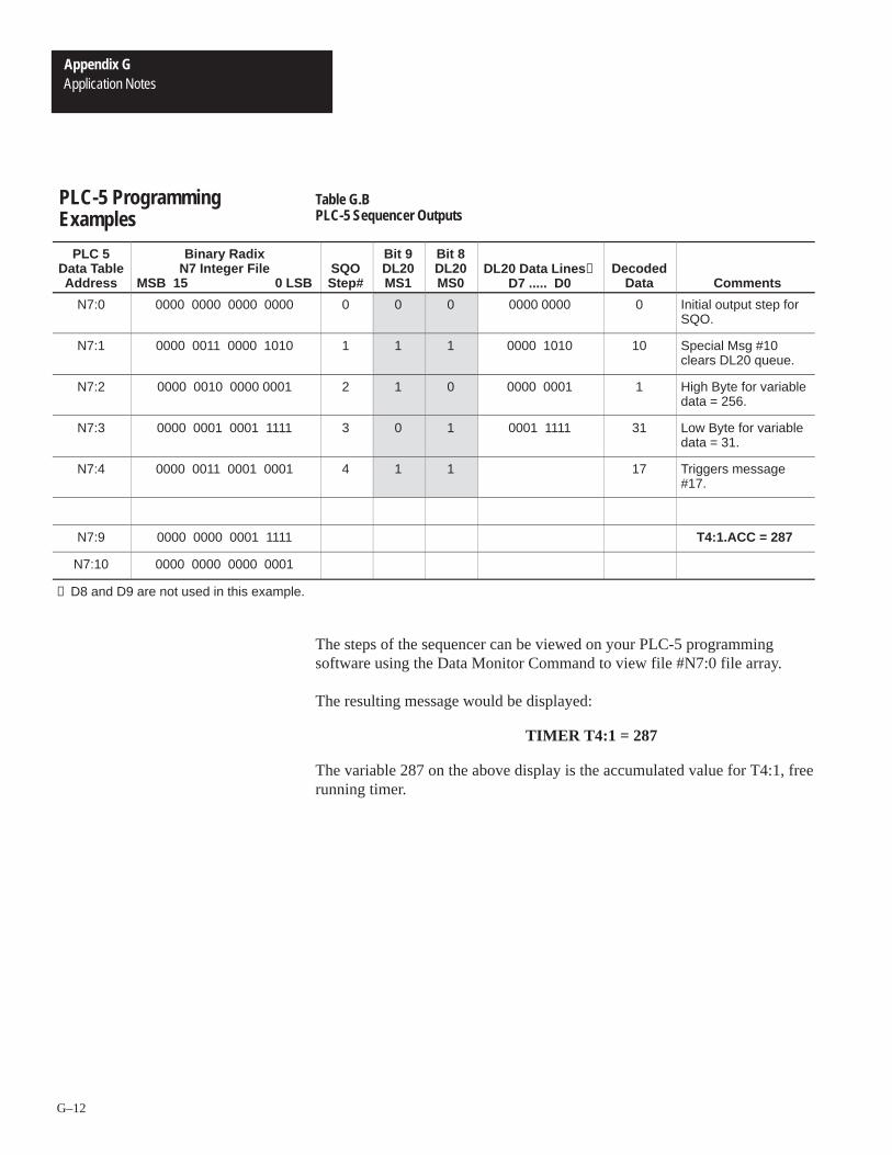
Appendix GApplication Notes
G–12
Table G.BPLC-5 Sequencer Outputs
PLC 5Data TableAddress
Binary RadixN7 Integer File
MSB 15 0 LSBSQOStep#
Bit 9DL20MS1
Bit 8DL20MS0
DL20 Data Lines ①D7 ..... D0
DecodedData Comments
N7:0 0000 0000 0000 0000 0 0 0 0000 0000 0 Initial output step forSQO.
N7:1 0000 0011 0000 1010 1 1 1 0000 1010 10 Special Msg #10clears DL20 queue.
N7:2 0000 0010 0000 0001 2 1 0 0000 0001 1 High Byte for variabledata = 256.
N7:3 0000 0001 0001 1111 3 0 1 0001 1111 31 Low Byte for variabledata = 31.
N7:4 0000 0011 0001 0001 4 1 1 17 Triggers message#17.
N7:9 0000 0000 0001 1111 T4:1.ACC = 287
N7:10 0000 0000 0000 0001
① D8 and D9 are not used in this example.
The steps of the sequencer can be viewed on your PLC-5 programmingsoftware using the Data Monitor Command to view file #N7:0 file array.
The resulting message would be displayed:
TIMER T4:1 = 287
The variable 287 on the above display is the accumulated value for T4:1, freerunning timer.
PLC-5 ProgrammingExamples

Appendix GApplication Notes
G–13
Figure G.4PLC-5 Ladder Program (Messages with Variable Data)
BTD
TONTIMER ON DELAYTimer T4:1Time Base 1.0Preset 1250Accum 287
TON
SQO
DN
T4:0
DN
T4:0
DN
T4:1
SEQUENCER OUTPUTFile #N7:0Mask 03FFDest O:002Control R6:0Length 4Position 0
(EN)
(DN)
TIMER ON DELAYTimer T4:0Time Base 0.01Preset 3Accum 1
(EN)
(DN)
(EN)
(DN)
(END OF FILE)
MVMMASKED MOVESource T4:1.ACC
287Mask 00FF
Dest N7:931
Rung 2:0
Rung 2:1
Rung 2:2
Rung 2:3
BIT FIELD DISTRIBSource T4:1.ACC
287Source bit 8Dest N7:10
1Dest bit 0Length 8
Rung 2:4
MVMMASKED MOVESource N7:10
1Mask 00FF
Dest N7:2513
Rung 2:5
MVMMASKED MOVESource N7:9
31Mask 00FF
Dest N7:3287
Rung 2:6

Appendix GApplication Notes
G–14
Rung Descriptions (Figure G.4)
Rung 2:0Each time input T4:0/dn is true, the sequencer output instruction outputsthe next step. The sequencer done bit is set when the sequencer reachesrung 2:4. The sequencer then resets itself and begins again.
Rung 2:1Timer T4:0 is a free running timer which drives the SQO. A preset valueof 3 provides a pulse every 30 msec.
Rung 2:2Timer T4:1 is a free running timer which generates the variable data forthe DL20.
Rung 2:3Masks off the low byte data from T4:1.ACC and moves it to lower byte ofN7:9. The low byte data is now in a format that can be output to theDL20 data lines (D0 through D7).
Rung 2:4Transfers or distributes the high byte of T4:1.ACC to the lower byte ofN7:10. The high byte data is now in a format that can be output to theDL20 data lines (D0 through D7).
Rung 2:5Takes the high byte data at N7:10 and moves it to N7:2 for use with theSQO. The upper byte of N7:2 is preloaded with the correct bit pattern tocontrol the strobe lines using the Data Monitor. This has the effect of alogic OR for the changing high byte variable data and the constant strobebit settings.
Rung 2:6Takes the low byte data at N7:9 and moves it to N7:3 for use with theSQO. The upper byte of N7:3 is preloaded with the correct bit pattern tocontrol the strobe lines using the Data Monitor. This has the effect of alogic OR for the changing low byte variable data and the constant strobebit settings.
PLC-5 ProgrammingExamples

Appendix GApplication Notes
G–15
The following parameters are configured within the SET PARALLEL PORTmenu of the DL20.
HI TRUE LOGIC? (Y for PLC-2/PLC-5 example)
Selecting Y (yes) means that the DL20 is expecting the parallel inputs to behigh (ON) when a logic 1 is represented.
Selecting N (no) means that the DL20 is expecting the parallel inputs to below (OFF) when a logic 1 is represented.
BINARY MSG DATA? (N for PLC-2 example) (Y for PLC-5 example)
Selecting Y (yes) means that the DL20 will expect message triggers in abinary format. (Binary format works well with the PLC-5)
Selecting N (no) means that the DL20 will expect message triggers in a BCDformat. (BCD format works well with the PLC-2)
BINARY VAR DATA? (N for PLC-2 example). (Y for PLC-5 example)
Selecting Y (yes) means that the DL20 will expect variable data to bestrobed in a binary format.
Selecting N (no) means that the DL20 will expect variable data to be strobedin a BCD format.
TIME SAMPLE? (Y for PLC-2 / PLC-5 example)
Selecting Y (yes) means that all parallel port data will be sampledautomatically at a rate determined by the SCAN TIME. If DC parallel portoperation was selected the user is also prompted for DEBOUNCE TIME.
Selecting N (no) means that the user wishes to use the edge triggered strobe(ETS) input to strobe all data into the parallel port. The user is thenrestricted to a DC voltage interface and must select “high to low” or “low tohigh” edge sensing for the ETS input. The ETS lines of the DL20 areprovided for use with other manufacturers programmable controllers havingoutput modules with strobe lines.
USE NG 1/2 SER A,B? (N for PLC-2 / PLC-5 example)
Selecting Y (yes) means that a Parallel Input Converter (Catalog No.2706-NG1, -NG2 Series A or B) is being used. TIME DRIVEN must havebeen selected previously.
Selecting No (no) means that a DC parallel interface or Parallel InputConverter (Catalog No. 2706-NG1, -NG2 Series C or later) is being used.
DL20 Parallel PortConfiguration
Appendix GApplication Notes
G–16
SCAN RATE: (4 for PLC-2/PLC-5 example)
If TIME DRIVEN mode was selected previously, then the value enteredrepresents the period between samplings of the parallel port. The valueentered is in units of 1.95 milliseconds.
Example: 28 = 28 x 1.95 = 54.6 milliseconds between samplings.
Important: You must be sure that data (each step) is present on the parallelport for at least the scan rate.
If a Parallel Input Converter (Catalog No. 2706-NG1 or -NG2 Series A or Bis used, the SCAN RATE range is 28 - 255 (54.6 - 500 ms). If not, the rangeis 4 - 255 (7.8 ms - 500 ms).
DEBOUNCE TIME: (1 for PLC-2/PLC-5 example)Not applicable for applications using Parallel Input Converters (Catalog No.2706-NG1, -NG2 Series A or B).
The debounce time is in units of 1.95 milliseconds. The range is 1 - 255.Debounce time determines how many samples are evaluated during thesampling period as determined by the scan rate selected. For example, if adebounce time of 5 is selected, then 5 samples are taken 1.95 millisecondsapart. All of these samples must match for the data to be read by the DL20.The debounce time should be at least 3 less than the scan rate.
For AC parallel interface applications using Parallel Input Converters(Catalog No. 2706-NG1, -NG2 Series A or B), data should be present (eachstep of sequencer) at the parallel port for at least 180 milliseconds.
For DC parallel interface applications, data should be present (each step ofsequencer) for at least 20 milliseconds. These are the minimum allowedvalues for the sequencer step timer (031 in the PLC -2 example or T4:1 in thePLC-5 example).
To determine update time, multiply the time interval between sequencer stepsby the number of sequencer steps. In the PLC-2 variable data example, timer031 in rung 2 determines the time interval between steps. For a setting ofPR010 (100 milliseconds), the update time for the variable data in thisexample of 8 steps, will be 800 milliseconds (100 ms x 8).
DL20 Parallel PortConfiguration
Variable DataUpdate Times

Appendix GApplication Notes
G–17
The following connections are applicable to the program examples shownpreviously.
The standard voltage levels required for the DL20 parallel port are 5 to 30VDC. When using DC Output Modules, an external power supply of theappropriate voltage level and current capacity is required.
AC Output Modules can be used, however, these applications require one ofthe Parallel Input Converters as described below. The need for an externalDC power supply is eliminated.
2706-NG1 - Display Mounted 120VAC Parallel Input Converter.
2706-NG2 - Panel Mounted 120VAC Parallel Input Converter.
Figure G.5 shows connections between a parallel Input Converter and ACOutput Module (Catalog No. 1771-OA).
Figure G.6 shows connections between a DL20 and DC Output Modules(Catalog No. 1771-OB or -OG)
Figure G.7 shows connections between a DL20 and High Density OutputModule (Catalog No. 1771-OBD).
Parallel Interface Connections

Appendix GApplication Notes
G–18
Figure G.5Parallel input Converter to AC Output Module
00-07 10-17
A
0
1
2
3
4
5
6
7
8
A
0
1
2
3
4
5
6
7
8
120VAC AC NEUHOT PWR
1771-OA AC Output Modules (120 VAC)
Parallel InputConverter Terminals
D9 D8 D7 D6 D5 D4 D3 D2 D1 MS1 MS0AC
COMDO

Appendix GApplication Notes
G–19
Figure G.6DL20 to DC Output Module (Catalog No. 1771-OB, -OG)
00-07 10-17
A
0
1
2
3
4
5
6
7
8
A
0
1
2
3
4
5
6
7
8
+ 12-24 VDC (OB) -or
+ 5 VDC (OG) -DL20 Terminals
1771-OB DC Output Modules (12-24 VDC)or
1771-OG DC Output Modules (5VDC)
D9 D8 D7 D6 D5 D4 D3 D2 D1 MS1MS0 GNDDO
Set both internal switches in the OG module ON forhigh true logic.
+5VDCOUT
Important Note: The 1771-OG TTL output modules 5VDC signals aremore noise susceptible than 12-24 DC signals. In applications where noisemay be a problem, it is strongly recommended that a 1771-OB DC outputmodule be used.
!ATTENTION: Do not connect to terminal 22 (+5 VDC OUT).Applying any voltage to this terminal will damage the DL20.
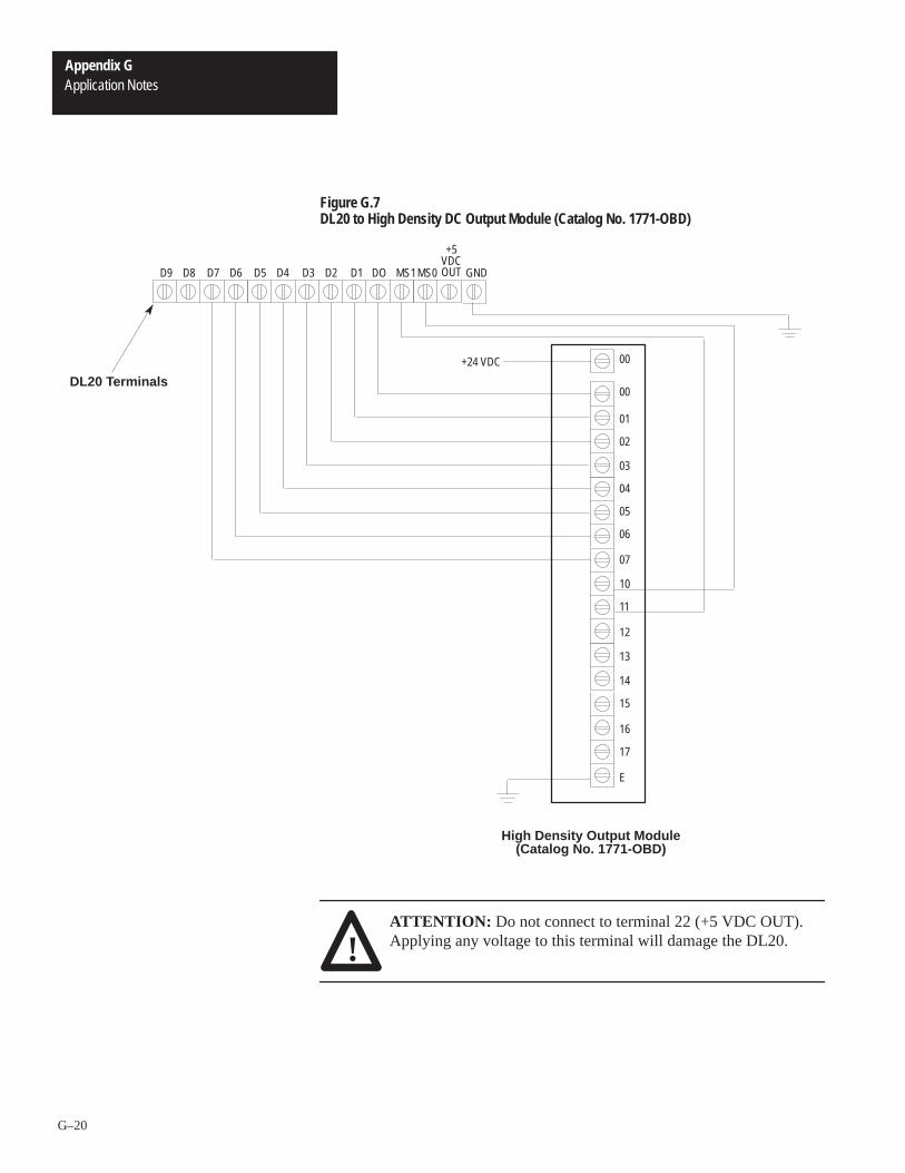
Appendix GApplication Notes
G–20
Figure G.7DL20 to High Density DC Output Module (Catalog No. 1771-OBD)
DL20 Terminals
D9 D8 D7 D6 D5 D4 D3 D2 D1 MS1MS0 GNDDO
00
01
02
03
04
05
06
07
10
11
12
13
14
15
16
17
E
High Density Output Module(Catalog No. 1771-OBD)
+5VDCOUT
00+24 VDC
!ATTENTION: Do not connect to terminal 22 (+5 VDC OUT).Applying any voltage to this terminal will damage the DL20.

A–B HAppendix
H–1
120 VAC Parallel Input Converters
The 110/120V AC Parallel Input Converters connect to the parallel port of aDL20 one, two, or four line display. Input converters allow AC connectionsto the DL20 parallel port which normally accepts DC voltages from 5–30volts. The Parallel Input Converter converts the AC signal to either pulsatingor constant 5V DC depending upon which series converter you use:
• Series A and B Parallel Input Converters accept 120V AC �10%, 60 Hzinput signals and convert them to a pulsating 5V DC input signal to theDL20 parallel port.
• Series C and later Parallel Input Converters accept the same AC inputsignals, but convert them to a constant 5V DC input. An external powersupply is not needed when the Parallel Input Converter is installed.
Appendix D shows the converter dimensions.
Description

Appendix HParallel Input Converters
H–2
Figures H.1 and H.2 provide block diagrams of the converter circuits.
Figure H.1Series A and B Parallel Input Converter Block Diagram
Common
D0
D0
Common
120 VAC
Converter Circuit Input to DL20
VDC
0
5
Time
AC Input On AC Input Off
Figure H.2Series C and Later Parallel Input Converter Block Diagram
Common
D0
D0
Common
120 VAC
Converter Circuit Input to DL20
VDC
0
5
Time
AC Input On AC Input Off+
The Parallel Input Converter is available in two different mounting styles:
• Catalog Number 2706–NG1 is a display mounted input converter whichmounts directly to the parallel port terminals 11A through 22. No wiringbetween the display and the converter is necessary. With the 2706–NG1installed, the overall depth of the display is increased by 0.46 inches.
• Catalog Number 2706–NG2 is panel mounted and wired to terminals 11Athrough 22 of the DL20 parallel port.
Note: A Parallel Input Converter does not fit inside the 2706–NE1 or2706–NE2 enclosure. If a parallel input converter is used with a display inone of these enclosures, use a panel–mounted input converter (CatalogNumber 2706–NG2) in a separate enclosure.
Terminals on both input converters are marked identically to the terminals onthe back of the DL20.
Description

Appendix HParallel Input Converter
H–3
You will need to configure the parallel port to communicate with the inputconverter and determine the timing for data transfers between the DL20 andthe converter.
Use the instructions below to set up the DL20 parallel port for operation withSeries A, B, C or later Parallel Input Converters.
1. Select the AC input mode of the parallel port when programming theDL20. You can do this by accessing the special function Set Up I/O Portsand answering appropriately to the prompt USE NG 1/2 SER A,B?Answering Yes to this prompt selects an AC sampling method.Answering No selects a DC sampling method.
2. Select a scan rate of 28 (default) for AC sampling with Parallel InputConverters (Catalog No. 2706-NG1, -NG2 Series A, B, C or later). Thescan rate is used to determine the minimum amount of time that stabledata must be present on the input terminals of the AC converter to allowfor two samples of the parallel port.
3. If the Parallel Input Converter (Catalog No. 2706-NG1, -NG2 Series C orlater) is used, the debounce value must also be specified. Use the value of25 ms for the debounce.
Minimum Data Hold Times (MDHT) values listed below are based on a scanrate of 28.
Series A or B Converter MDHT = 180 msSeries C and Later Converter MDHT = 100 ms
The following diagram shows the relationship between Minimum Data HoldTimes (MDHT) and Minimum Time Between Messages (MTBM).
Timing Diagram
5 - 30VDC
0VDC
Start of Message 1 Start of Message 2
MDHT
MTBM
PLC Output /DL20 Input Signals

Appendix HParallel Input Converters
H–4
4. To insure that the DL20 message or variable queue does not overflowresulting in lost messages/variables, determine the minimum timebetween message (MTBM) triggers (see Table H.A). The MTBM iscritical for applications where variables are being updated fast. MinimumTime Between Messages (MTBM) values listed below are based on ascan rate of 28.
Table H.AMTBM Values (Scan Rate = 28)
Parallel Input Converter Dataliner MTBM
Series A, B, & C One / Two Line MTBM = MDHT
Series A & B Four Line 360 ms
Series C & Later Four Line 310 ms
Use the following instructions to mount and connect the Parallel InputConverter to the DL20. Instructions are provided for both the displaymounted and the panel mounted versions. The approximate mountingdimensions are shown in Appendix D.
!ATTENTION: Before installing the parallel input converter,disconnect all power from the DL20.
Display Mounted Version (Catalog No. 2706–NG1)
1. Mount the converter to the back of the DL20 by positioning it directlyunder parallel port terminals 11A through 22 (D9–D0, MS1, MS0, and+5V DC out).
2. Fasten the converter to the display using the two captive #6–32 screws(supplied). Tighten the two #6 screws to 10 in.–lbs.
3. Tighten terminal screws 11A through 22 on the DL20 for electricalcontinuity.
Installation

Appendix HParallel Input Converter
H–5
Panel Mounted Version (Catalog No. 2706–NG2)
1. Secure the converter to the panel.
2. Connect the input converter to the DL20 by wiring terminals 11A through22 of the 2706–NG2 to the identically numbered terminals on the DL20.
Connecting the AC Inputs
1. Connect up to twelve 120V AC �10%, 60 Hz inputs to the 120V ACsource inputs (D9 through D0, MS1 and MS0) on the parallel inputconverter.
2. Connect the AC common to the terminal marked AC COM on theconverter.
Important: The AC voltage on all inputs to the Parallel Input Convertermust be in phase i.e., they must all come from the same power source.
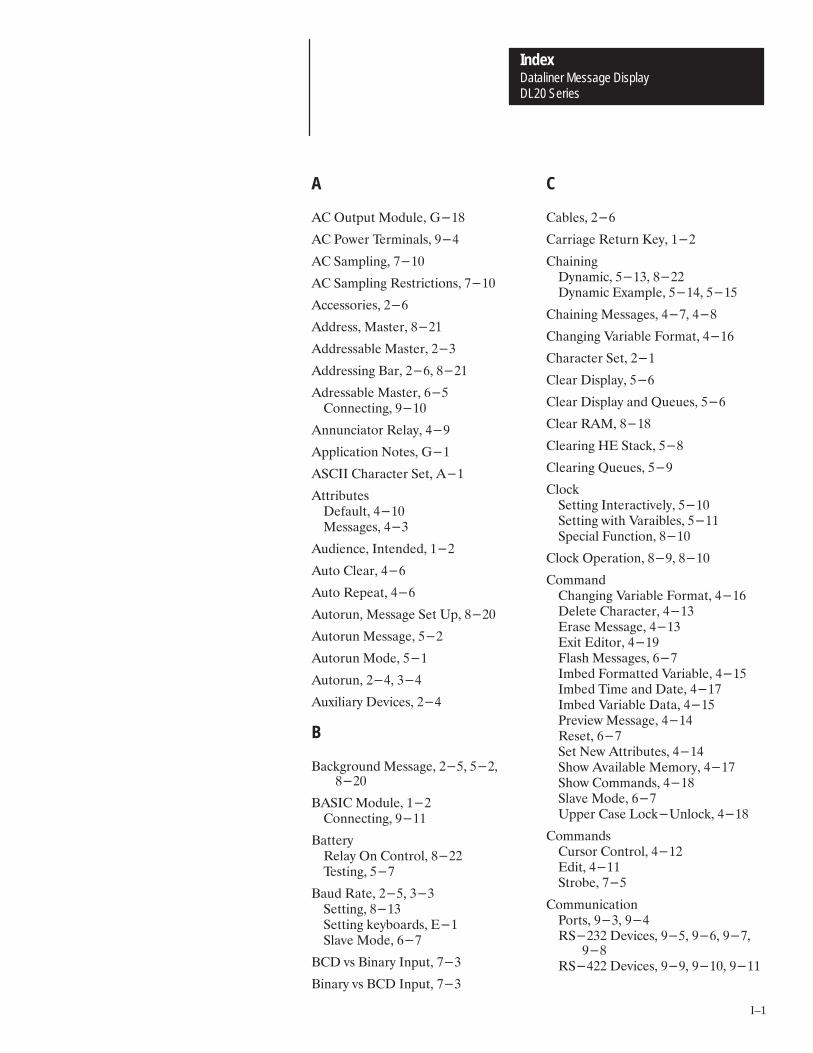
A–BDataliner Message DisplayIndex
DL20 Series
I–1
A
�� �54154 �0&5-'� ����
�� �07'2 '2.+/#-3� ��
�� �#.1-+/)� ����
�� �#.1-+/) �'342+%4+0/3� ����
�%%'3302+'3� ��
�&&2'33� �#34'2� ����
�&&2'33#$-' �#34'2� ���
�&&2'33+/) �#2� ��� ����
�&2'33#$-' �#34'2� ��0//'%4+/)� ���
�//5/%+#402 �'-#9� ��
�11-+%#4+0/ �04'3� ���
����� �*#2#%4'2 �'4� ���
�442+$54'3�'(#5-4� �����'33#)'3� ���
�5&+'/%'� �/4'/&'&� ���
�540 �-'#2� ��
�540 �'1'#4� ��
�54025/� �'33#)' �'4 !1� ����
�54025/ �'33#)'� ��
�54025/ �0&'� ��
�54025/� ���� ���
�58+-+#29 �'6+%'3� ���
B
�#%,)205/& �'33#)'� ��� �������
����� �0&5-'� ����0//'%4+/)� ���
�#44'29�'-#9 �/ �0/420-� ���� '34+/)� ��
�#5& �#4'� ��� ����'44+/)� �����'44+/) ,'9$0#2&3� ����-#6' �0&'� ��
��� 63 �+/#29 �/154� ���
�+/#29 63 ��� �/154� ���
C
�#$-'3� ��
�#22+#)' �'452/ �'9� ���
�*#+/+/)�9/#.+%� ���� �����9/#.+% �8#.1-'� ���� ��
�*#+/+/) �'33#)'3� ���� ���
�*#/)+/) "#2+#$-' �02.#4� ���
�*#2#%4'2 �'4� ���
�-'#2 �+31-#9� �
�-'#2 �+31-#9 #/& �5'5'3� �
�-'#2 ���� ����
�-'#2+/) �� �4#%,� ��
�-'#2+/) �5'5'3� �
�-0%,�'44+/) �/4'2#%4+6'-9� ����'44+/) 7+4* "#2#+$-'3� ����1'%+#- �5/%4+0/� ����
�-0%, �1'2#4+0/� �� � ����
�0..#/&�*#/)+/) "#2+#$-' �02.#4� ����'-'4' �*#2#%4'2� �����2#3' �'33#)'� �����8+4 �&+402� ��� �-#3* �'33#)'3� ���.$'& �02.#44'& "#2+#$-'� ����.$'& +.' #/& �#4'� �����.$'& "#2+#$-' �#4#� ����2'6+'7 �'33#)'� �����'3'4� ���'4 �'7 �442+$54'3� �����*07 �6#+-#$-' �'.029� �����*07 �0..#/&3� �����-#6' �0&'� ��!11'2 �#3' �0%,�!/-0%,� ����
�0..#/&3�52302 �0/420-� �����&+4� �����420$'� ��
�0..5/+%#4+0/�0243� ��� �������� �'6+%'3� �� �� ���
�������� �'6+%'3� � � ���� ���
DL20 SeriesDataliner Message DisplayIndex
I–2
�20071,&$6,215� (66,1* �2465� ����
�20071,&$6,215 �36,215� ���
�211(&624� �(;%2$4'� ��
�211(&6245� (4,$/ �246� ���
�21642/ �2'(5� /$8( �2'(� ��
�218(16,215� ���
�218(45,21 !$%/(� � ���� ���
�218(46(4� �$4$//(/ �1376� ��� ���
�74524� �21642/� ���
D
�� � �� !(40,1$/5� ��
�$6$ �240$6� (4,$/ �246� ����$4$//(/ �246� ����
�$6$ �2/' !,0(� ���� ���
�$6$ �,1(!(40,1$/5� ��#$/7(5 ���� �#$/7(5 �,1$4;� �
�$6$ �,1(5� �$4$//(/� ��
�$6$ �(&24'(4� ���
�$6$ �(&24'(4 �$%/(5� ���
�$6$ �(&24'(45� �� � ���� ������� ���� ���
��� !������� ����
�$6$ �(-(&6,21� �
�$6$ $03/,1*�8(16 �4,8(1� ��� ��!,0( �4,8(1� ��� ���
�$6$ !4$15)(4� ���
�$6$ !4,**(4 �2'(5� ���
�� �76376 �2'7/(� ����� ����
�� $03/,1*� ���
�(%271&(� ���� ����
�(%7* �2'(� ���� ����
��� !(40,1$/5� ���
�(&,0$/ �2,16� ���
�()$7/65� �664,%76(5� ���
�(/(6,1* �+$4$&6(45� ��
�(5.623 "5(� ��
�,0(15,215� ����1&/2574(� �� �/75+ �$1(/ �2716� ���8(4$//� ����$1(/ �76276� ����$4$//(/ �1376 �218(46(4� ���
�,5$%/( �� 6$&.� ����
�,53/$;�/($4,1*� ��� 3(&,),&$6,215� ����#$&770 �/724(5&(16� ���
����� �5 /$8(� ���
���� �$17$/� ���
���� �$17$/� ���
���� �8(48,(9� ���
�;1$0,& �+$,1,1*� ���� ����1$%/(� �����:$03/(� ���� ����
E
�&+2 62 /$8(5� ���
�'*( !4,**(4(' 642%(� � !(40,1$/5� ��#2/6$*( $1' �744(16� ��
�'*( !4,**(4(' 642%( ��! �� 3(&,),&$6,215� ����
�',6�+$1*,1* #$4,$%/( �240$6� ����200$1'5� ����74524 �21642/� ����(/(6( �+$4$&6(4� ���4$5,1* �(55$*(5� ���:,6,1* �',624� ����0%(' !,0( $1' �$6(� �� �0%('',1* �$6$� ����(55$*(5� ����4(8,(9 �(55$*(� �� (6 �(9 �664,%76(5� �� +29 �8$,/$%/( �(024;� �� +29 �200$1'5� ���"33(4 �$5( �2&.�"1/2&.� ���
�',6 �200$1'5� ���
�',6 �2'(� ��
�',6,1* �(55$*(5� ���
�1$%/( �� 6$&.� ����

Dataliner Message DisplayIndex
DL20 Series
I–3
�0&.1463(� ���,/(04,104� ���
�05(3 �(:� ���
�05(3,0* �60 �1'(� ��
�07,310/(05� �2(&,),&$5,104� ����
��� � ������� ����
��������� �2(3$5,10� ����04(35,0*� ����31*3$//,0*� ��� 3$04)(33,0* �,.(4� ���
����� �31*3$//,0*� ���
�3$4,0* �(44$*(4� ����
�33134� �.$**,0*� ����
�45,/$5,0* �(/13: !4$*(� ����
� �� ���
� � (3/,0$.4� ��
�7(05 �3,7(0 �$/2.,0*� ���� ��
�9$/2.( �(44$*(� ���
�9,5,0* �',513� ���
F
�.$**,0* �33134� ����
�.$4+,0* �(44$*(4� �� � ��
�64(� �(2.$&(/(054� ���� ����
G
�(55,0* �5$35('� ���
��� (3/,0$.� ��
�3160',0*� ���
H
�$.5 �60 �1'(� �
�$0'4+$-,0*� �3,05(3� ��
��� � ��� ��
�,4513,&$. �7(05 �(&13',0*� �������� ���
�,4513,&$. �7(05 �5$&-�.($3,0*� ���,4$%.,0*� ����0$%.,0*� ���
�3,05,0*� ���512 �3,05,0*� ��
�1.' ,/(� �$5$� ����� ����
I
�..(*$. �(44$*( 3,**(3� ��� ����
�/%('',0* ,/( $0' �$5(� ����
�/%('',0* "$3,$%.(4� ���
�0'6453,$. (3/,0$.4� ���#,5+ �$5$ �(&13'(34� ���� ���
�0),0,5( �+$,04� ���
�0,5,$. �5$3562� ���
�0265 �107(35(34� ���
�0265 �18(3� �2(&,),&$5,104� ����
�045$..$5,10� ��
�05(0'(' �6',(0&(� ���
�05(3$&5,7( �.1&- �(55,0*� ���
�07,4,%.( �(44$*(� ��� ����
K
�(:%1$3'� �100(&513� ��
�(:%1$3'4� ���� ���100(&5,0*� ���� ����(55,0* �$6' �$5(� ���8,5+ �$5$ �(&13'(34� ���� ��
L
��� � ��
�,0( �1'(� ���
�,0( �(.(&5,10� ���
�1$',0* $0' !0.1$',0* �6(6(4� ��
�1*,& �(7(.4� ���
M
�$,0 �(06� ���(5630,0* 51� ��
�$,05(0$0&(� ��
�$06$. �7(37,(8� ���
�$45(3�''3(44$%.(� �

DL20 SeriesDataliner Message DisplayIndex
I–4
)6 "3 �)17� ��� )673� ���
�%56)4 �((4)55� ���//)+%/ �(4)55)5� ��� )66-1+� ���
�)024;�%'.73� ����56-0%6-1+ "5%+)� ��� -<)� ���� ���
�)17�/2'.� ���(-6 �2()� �������� � �%-1� ����4-16 �)55%+)5� ���)5)6� ��� )6 "3 �%56)4� ��� )6 "3 �%4%//)/ �246� ��� )6 "3 )4-%/ �246� ��� 3)'-%/ �71'6-215� ��!%3) �3)4%6-215� �
�)55%+)�664-&76)5� ���762 �71� ��� ����%'.+4271(� ��� ��� ����,%-1-1+� ��� � �;1%0-' �,%-1-1+� ���(-6-1+� ��� ����:%03/)� ����/%5,-1+� ���//)+%/ !4-++)4� ���� ����18-5-&/)� ��� ����70&)4� ���4-16-1+� �� ��� � /%8)� � 3)'-%/� ��� �� 3)'-%/� �/)%4 �-53/%;� �� 3)'-%/� �/)%4 �-53/%; %1( �7)7)5�
�� 3)'-%/� �/)%4 �� 6%'.� � 3)'-%/� �/)%4 �7)7)5� �� 3)'-%/� �/)%4 �7)7)5� �%/6 �71
�2()� �� 3)'-%/� �-5%&/) �� 6%'.� ��� 3)'-%/� �1%&/) �� 6%'.� ��� 3)'-%/� �4-16 �� 6%'.� �� 3)'-%/� �)5)6 ����� �� 3)'-%/� �)570) �71 �2()� �
3)'-%/� )6 �/2'. �16)4%'6-8)/;����
3)'-%/� )6 �/2'. 9-6, #%4-%&/)5����
3)'-%/� 623 �4-16-1+ �� 6%'.��
3)'-%/� !)56 �%66)4;� �� 624-1+� ��!%3-1+� �� ��!4-++)4 �:%03/)� ����!4-++)4 �7)7)� ��$%-6 !-0)� �$24.5,))65� ���
�)55%+) �(-6-1+ 2*69%4)� ���
�)55%+)5�/%5,-1+� ��� 624-1+� ���
�2()�762471� ���%6% !4-++)4� ���)&7+� �� �(-6� ���-1)� ��71� �� '42//� � /%8)� ���
�2(7/)�� �76376� ��� �� �76376� ����� ����
�2716-1+ �-65� ���
�28-1+ �74524� ���
� � � � � !)40-1%/5� ��
N
�"��� ��
�"�� � ���
O
�**/-1) �42+4%00-1+ 2*69%4)� �������
�8)48-)9����� ����%17%/� ���

Dataliner Message DisplayIndex
DL20 Series
I–5
P
�$4$..(. �$6$ �,0(5� ���
�$4$..(. �0276 �108(46(4� ���� ����.1&- �,$*4$/� ����100(&6,0* �� �02765� ���100(&6,105� �����,/(05,105� ���056$..$6,10� ��
�$4$..(. �146� ���� ���� �76276 �10),*74$6,10� ����� �76276 �10),*74$6,10� ���� �76276 �10),*74$6,10� ������� �$6$ �,0( "$.7(5� ���,0$4; �$6$ �,0( "$.7(5� ���,0$4; 85 ��� �0276� ����$6$ �14/$65� ���$6$ �$/2.,0*� ���()$7.6 "$.7(5� ����(5&4,26,10� ����:$/2.(� �����0276 �108(46(45� �� �1*,& �(8(.5� ���� ���('7&,0* �76276 �(37,4(/(065�
���� �����$/2.,0* �(6+1'5� �� �(6 !2 �(07� ����(66,0*� ��� ����2(&,),&$6,105� �����641%( �,0(5� ��!5,0*� ���
�$4$..(. �146 (4/,0$.5� ��
�$4,6;� ��� ���� ���
����� �:$/2.(� ���� ��� ������� ���� ��
���� �:$/2.(� ���� ����� �������� ����
�146�$4$..(.� ���� ���(4,$.� ���� ���
�19(4 �14'� �100(&6,0*� ���
�19(4 �0 (56,0*� ��
�4(8,(9,0* �(55$*(5� ��
�4,06(4� �$0'5+$-,0*� ���
�4,06,0*� �(55$*(5� �
�4,06,0* �,5614,&$. �8(06 �6$&-� ��
�4,06,0* �(55$*(5� ��� �
�41*4$//$%.( �10641..(4�:$/2.(5� ����06(4)$&(� ����76276 �,*0$.5� ���
�41*4$//(4� �100(&6,0*� ���
�41*4$//,0* �(8,&(5� ���
�41*4$//,0* (4/,0$.� ����100(&6,0*� ���
�41/265�(5&4,26,10� ���7/(4,&� ��#(5��1� ��
�4161&1.� �.$8( �1'(� ���
�7%.,&$6,105� �(.$6('� ���
Q
�7(7(�$2$&,6;� ��$6$� ���:$/2.(5� ��1$',0* $0' !0.1$',0*� ���(55$*( 4,**(4� ��
�7(7(5� �.($4,0*� ��� ��
�7(7(5 $0' 4,**(45� ��
R
���� �.($4,0*� ��
�($',0* $2(5� ��
�(&14'(45� �$6$� ��
�(&14',0*� �,5614,&$. �8(06� ������
�(.$6(' �7%.,&$6,105� ���
�(.$;� ���10641.� ���
�(.$; �10641.� ���
�(2.$&(/(06 �75(5� ����
�(5(6 ����� ��� ���
�(5(6 �70&6,10� ���
�(57/( �70 �1'(� �
������ (4/,0$.� ���

DL20 SeriesDataliner Message DisplayIndex
I–6
������ �024� �����0//'%4+/) �&&2'33#$-' �#34'23�
����0//'%4+/) ����� �0&5-'� ����0//'%4+/) ���� �-#6'3� �
�5/ �0&'� ���/4'2+/)� ���8+4+/)� ���#-4+/)� � �'35.+/)� ��
S
�%#/ �#4'� ���
�%20-- �0&'� ���
�'-( �'34� ���
�'2+#- �024� ��� ���0//'%4+/) ��� �/&5342+#-
�'2.+/#-3� ���0//'%4+/) ����� �0&5-'� ��0//'%4+/) �#4# �'%02&'23� ���0//'%4+/) ��� �'2.+/#-3� ���0//'%4+/) ���0&5-'� ��0//'%4+/) ��� �� 02 �0.1#4+$-'�
��0//'%4+/) ��� "� 02 �0.1#4+$-'�
��0//'%4+/) �20)2#..+/) �'2.+/#-3�
���0//'%4023� ���#4# �8#.1-'� ���#4# �02.#4� ���'(#5-43� �����#2#.'4'23� ���'4 �1 �'/5� �����'44+/)� ����� �����1'%+(+%#4+0/3� �����'2.+/#-3� ���3+/)� ��
�'2+#- �0243� �'3%2+14+0/� ���
�'4 �1 �#34'2 �5/%4+0/� ���
�'4 �1 �#2#--'- �024 �5/%4+0/� ����
�'4 �1 �'2+#- �024 �5/%4+0/� ����
�'44+/) �-0%,�/4'2#%4+6'-9� ���!+4* #2+#$-'3� ���
�'44+/) �'7 �442+$54'3� ����
�*07 �0..#/&3� ����
�*07+/) �6#+-#$-' �'.029� ����
�-#6' �'33#)'3� ��
�-#6' �0&'� ��#5& �#4'� ���0/420- �0&'3� ���/4'2+/)� ��8+4+/)� ��2040%0-� ��'-#9 �0/420-� ��
�-#6' �0&' �#34'2� ���
�-#6'3� �+31-#9+/) �20.143� ����
�0(47#2'� �'33#)' �&+4+/)� ���
�1'%+#- �5/%4+0/� �'4 �1 �'2+#- �024�����
�1'%+#- �5/%4+0/3� ����-0%,� �� �-0%, �1'2#4+0/� �� � ��������� �20)2#..+/)� ����2+/4 �'33#)'3� ���� ����'3'4� �����'4 �1 �#34'2� ��� �'4 �1 �#2#--'- �024� �����'4 �1 �'2+#- �024� �����#1' �1'2#4+0/3� ��� ��
�1'%+#- �5/%4+0/3 �'/5� ���
�1'%+#- �'33#)'�5.$'2 �� ��5.$'2 ��� � �5.$'2 ��� ����5.$'2 ��� ����5.$'2 �� ����5.$'2 �� ����5.$'2 �� ��5.$'2 �� ���5.$'2 �� ���5.$'2 � ���5.$'2 � ���5.$'2 �� ���5.$'2 �� ���5.$'2 � �
�1'%+#- �'33#)'3� ��� �
�1'%+(+%#4+0/3�+31-#9� �����&)' �2+))'2'& �420$'� �����/6+20/.'/4#-� �����/154 �07'2� �����#2#--'- �024� ����

Dataliner Message DisplayIndex
DL20 Series
I–7
!*6.&1 �468� ����
!84'* �422&3)7���"� ������"� ����#��� ���
!8455.3, �� �6.38498� ���
!846.3, �*77&,*7� �
!864'*�),* "6.,,*6*)� ����3*243.(7� ����
!864'* �.3*7� ���
T
"&5* *(46)*6� !*8 #5� ���� ������� �� � ���
"&5*7 *&).3,� �� $*6.+=.3,� ���%6.8.3,� ��
"&5.3, �*77&,*7� ���� ��
"*62.3&1� �64,6&22.3,� �
"*62.3&1�*<*� ���
"*62.3&17� �$�� �#"� ����� �4;*6� ����� 8-649,- ��� ����"!� ������� ����!� � �!�� ����&6&11*1 �468� ���!*6.&1 �468� ��
"*78 �43.846� ����
"*78.3, �&88*6=� ���
".2* �6.:*3 !&251.3,� ���� ������ !&251.3,� ������ !&251.3,� ����
�*8-4)7� ����
"6&37+*66.3, �&8&� ���
"6&37+*66.3, $&6.&'1* �&8&� ���
"6.,,*67 &3) �9*9*7� ��
U
#3(-&3,*) �&8& */*(8.43� ���
#314&).3, &3) �4&).3, �9*9*7� ��
#55*6 �&7* �4(0�#314(0� ����
V
$&(992 �1946*7(*38 �.751&=� ��
$&6.&'1* �14(0 !*88.3,� ����
$&6.&'1* �&8&�-&3,.3, �462&8� ��� �<&251*� ����2'*)).3,� ����"6&37+*66.3,� ���;.8- �*(.2&1 �4.38� ����
$&6.&'1* �&8& #5)&8* ".2*7� ���
$&6.&'1* !8&(0 �258= �3).(&8.43����
$&6.&'1*7� ;.8- �*(.2&1 �4.38� ��
$*6.+=.3, "&5*7� ���
$��� ��
W
%&.8 ".2*� ���
%.6.3,�64(*)96*7� ��"*62.3&17� ��
%4607-**87� ���
%6.8.3, "&5*7� ��

DL20 EDIT COMMANDS
FunctionKeys Pressed
(Simultaneously)
Forward One Space Ctrl [L]
Back One Space Ctrl [H]
Up a Line(Move 20 characters to left within message)
Ctrl [K]
Down a Line(Move 20 characters to right within message)
Ctrl [J]
Delete a Character Ctrl [D]
Change or Review Message Attributes Ctrl [A]
Run Message Ctrl [R]
Erase Message Ctrl [E]
Toggle Uppercase Lock Ctrl [U]
Show Free Memory Ctrl [F]
Imbed Non-Decimal Point Variable Ctrl [V]
Imbed Formatted Decimal Point Variable Ctrl [X]
Change Variable Format Ctrl [C]
Imbed time and Date Ctrl [T]
Show Edit Commands Ctrl [S]
Quit Edit Ctrl [Q]

2
Rockwell Automation helps its customers receive a superior return on their investment by bringingtogether leading brands in industrial automation, creating a broad spectrum of easy-to-integrateproducts. These are supported by local technical resources available worldwide, a global networkof system solutions providers, and the advanced technology resources of Rockwell.
Worldwide representation.
Argentina • Australia • Austria • Bahrain • Belgium • Bolivia • Brazil • Bulgaria • Canada • Chile • China, People’s Republic of • Colombia • Costa Rica • Croatia • CyprusCzech Republic • Denmark • Dominican Republic • Ecuador • Egypt • El Salvador • Finland • France • Germany • Ghana • Greece • Guatemala • Honduras • Hong KongHungary • Iceland • India • Indonesia • Iran • Ireland • Israel • Italy • Jamaica • Japan • Jordan • Korea • Kuwait • Lebanon • Macau • Malaysia • Malta • Mexico • MoroccoThe Netherlands • New Zealand • Nigeria • Norway • Oman • Pakistan • Panama • Peru • Philippines • Poland • Portugal • Puerto Rico • Qatar • Romania • Russia • SaudiArabia • Singapore • Slovakia • Slovenia • South Africa, Republic of • Spain • Sweden • Switzerland • Taiwan • Thailand • Trinidad • Tunisia • Turkey • United Arab EmiratesUnited Kingdom • United States • Uruguay • Venezuela
Rockwell Automation Headquarters, 1201 South Second Street, Milwaukee, WI 53204-2496 USA, Tel: (1) 414 382-2000 Fax: (1) 414 382-4444Rockwell Automation European Headquarters, Avenue Hermann Debroux, 46, 1160 Brussels, Belgium, Tel: (32) 2 663 06 00, Fax: (32) 2 663 06 40Rockwell Automation Asia Pacific Headquarters, 27/F Citicorp Centre, 18 Whitfield Road, Causeway Bay, Hong Kong, Tel: (852) 2887 4788, Fax: (852) 2508 1846World Wide Web: http://www.ab.com
Publication 2706-814 – April 1993 40061-197-01(A)Copyright 1993 Allen-Bradley Company, Inc. Printed in USA