1 SAR Link Tele – alarma? Tele – vigilancia? Tele – control?
Upload
grantlercCategory
view
808download
1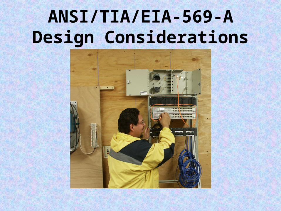
ANSI/TIA/EIA-569-ADesign Considerations
Purpose of the ANSI/TIA/EIA-569-A Standard
As the complexity of voice and data telecomm-unications has increased, standards have been established to ensure the operability, flexibility, manageability and longevity of these critical commercial support systems. Telecommunications now encompasses voice, data and video transmission of business information, fire/security, audio, environmental and other intelligent building controls over media that includes fiber optics, specialized copper data cabling, microwave and radiowave. This booklet concisely describes the architectural design elements of cabling pathways and dedicated rooms for telecommunications equipment.

Purpose of the ANSI/TIA/EIA-569-A Standard cont.
A multi-tenant commercial building has a life expectancy of at least 50 years. Software, hardware and communications gear have far shorter lifespans of one to five years. Moreover, in a multi-tenant environment, continuous moves, adds and changes are inevitable. It is the purpose of standards to guide design and ease future changes-by planning for the future now. These standards are intended to provide for a generic structured cabling plant, capable of running any voice or data application foreseeable in the next 10 to 15 years.

1. Electric Entrance 2. Telco Entrance 3. Telecom Equip. Rm 4. Data 5. Voice 6. Telecom Closet 7. Grounding & Bonding 8.
Underfloor System

Service Entrance Pathways For underground facilities, use a minimum 4-inch conduit or duct
constructed of PVC type B, C or D; multiple plastic duct; galvanized steel; fiber glass; with appropriate encasement. No more than two 90° manufactured bends are allowed (10 times the diameter). Drain slope should not be less than 12 inches per 100 feet. Recommended conduit fill varies but should not exceed 40 percent for more than two cables. Maintenance holes (typically 3,500 lb./sq. in., concrete) must be equipped with sump, corrosion-protected pulling iron, cable racks, grounded ladder, and only such power/light conductors as required for telecommunications support per NEC requirements.

Entrance Facilities Entrance facilities include the pathways for outside
carrier services, interbuilding backbone, alternate entrance and antennae entrance pathways. The entrance facilities consist of a termination field interfacing any outside cabling to the intrabuilding backbone cabling. The local telephone carrier is typically required to terminate cabling within 50 feet of building penetration, and to provide primary voltage protection. In buildings larger than 20,000 usable square feet, a locked, dedicated, enclosed room is recommended. Beyond 70,000-square feet, a locked, dedicated room is required, with a plywood termination field provided on two walls.
Entrance Facilities cont.• In buildings up to 100,000 usable square
footage, a wall-mounted termination field may serve as the entrance facility, using 3/4-inch plywood, 8-feet high. Beyond 100,000-square feet, rack-mounted and free-standing frames may also be required. Minimum space requirements are given as follows:
• Rule of Thumb: Allow one square foot of plywood wall mount for each 200 square-foot area of floor space.

Equipment Room
An equipment room is essentially a large telecommunications closet that may house the main distribution frame, PBXs, secondary voltage protection, etc. The equipment room is often appended to the entrance facilities or a computer room to allow shared air conditioning, security, fire control, lighting and limited access.
• Rule of Thumb: Provide 0.75 square feet of equipment room floor space for every 100 square feet of user workstation area.

Equipment Room cont.Location
Typically, rooms should be located away from sources of electromagnetic interference (transformers, motors, x-ray, induction heaters, arc welders, radio, radar) until interference is less than 3 V/m across the frequency spectrum. Avoid sources of flooding.
PerimetersTypically, no false ceiling; all surfaces treated to reduce dust; walls and ceiling painted white or pastel to improve visibility.

Equipment Room cont.
Limited AccessTypically, single or double 36” x 80" lockable doors. Other Typically, no piping, ductwork, mechanical equipment or power cabling should be allowed to pass through the equipment room. No unrelated storage.
HVAC24 hours/day, 365 days/year, 64°-75°F, 30%-55% humidity, positive pressure.

Equipment Room cont.Lighting
Typically, 8.5 feet high, providing 50-foot candles @ 3 feet above floor. Electrical Typically, a minimum of two dedicated 15A, 110VAC duplex outlets on separate circuits is required. Convenience duplex outlets shall be placed at 6-foot intervals around the perimeter. Emergency power should be considered and supplied, if available.
DustLess than 100 micrograms/cubic meter/24-hour period
Note: The term "typically" is applied here to indicate, where applicable, that these requirements also apply to other elements of the cabling system spaces. Lighting requirements, for instance, are largely identical for entrance facilities, equipment rooms and telecommunications closets.

Intrabuilding Backbone Pathways
Within a building, the intrabuilding backbone pathways extend between the entrance facilities, equipment room and telecommunications closets. Telecom closets should be stacked vertically above each other on each floor, and provided with a minimum of three 4-inch sleeves (a stub of conduit through the floor) for less than 50,000 square feet served. An equivalent 4" x 12" slot may be used in lieu of three sleeves. Firestopping is required. If closets are not vertically aligned, then 4-inch horizontal conduit runs are required. Include no more than two 90° bends between pull points. Pulling iron or eyes embedded in the concrete for cable pulling is recommended. Fill should not exceed 40 percent for any run greater than two cables.
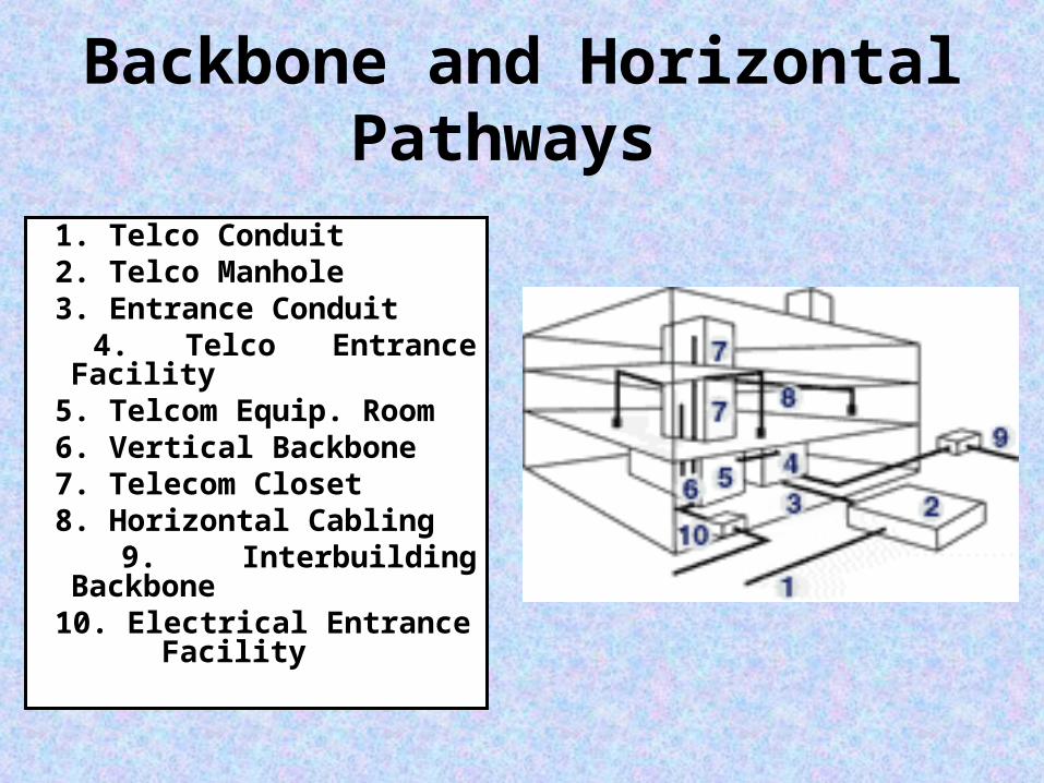
Backbone and Horizontal Pathways
1. Telco Conduit 2. Telco Manhole 3. Entrance Conduit 4. Telco Entrance Facility 5. Telcom Equip. Room 6. Vertical Backbone 7. Telecom Closet 8. Horizontal Cabling 9. Interbuilding Backbone 10. Electrical Entrance
Facility
Telecommunications Closet The telecommunications closet on each floor is the junction between backbone and horizontal pathways. It contains active voice and data telecommunications equipment, termination fields and cross-connect wiring.
More than one telecom closet per floor is required if distance to a work area exceeds 300 feet, or if floor area served exceeds 10,000 square feet. Recommended closet sizing is 10' x 11' for each 10,000 square-foot area served.
Power, lighting, air conditioning and limited access are typical. See requirements for Equipment Room. There are a minimum of three 4-inch firestopped backbone sleeves in the floor at the left side of a plywood termination field, which are ideally located near the door. A fire extinguisher is recommended.
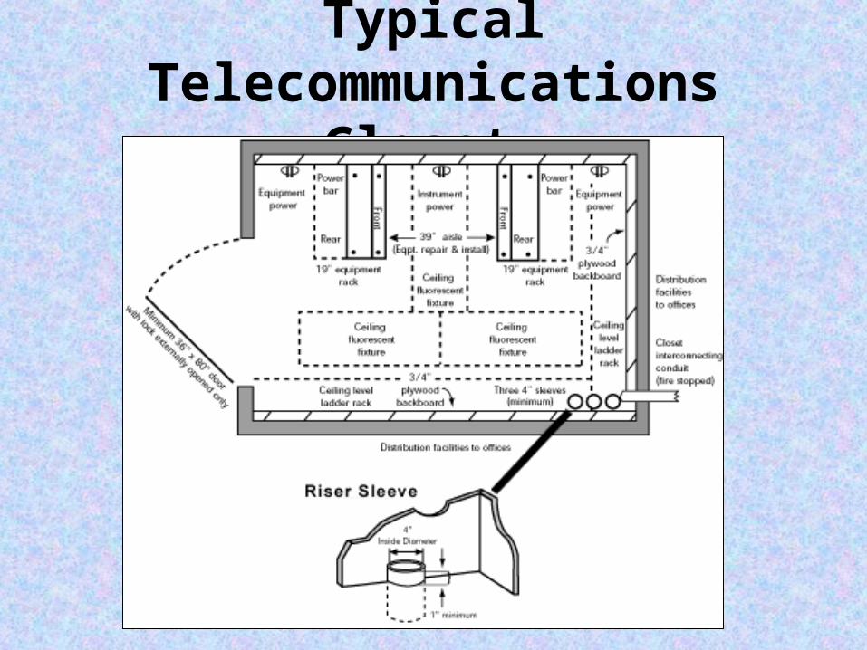
Typical Telecommunications Closet
Horizontal Pathways
Horizontal pathways extend between the telecommunications closet and the work area. A variety of generic pathway options are described. Choice of pathway(s) is left to the discretion of the designer. The most commonly employed pathway consists of cable bundles run from the telecom closet along J-hooks suspended above a plenum ceiling, fanning out once a work zone is reached, dropping through interior walls or support columns or raceways, and terminating at an information outlet (I/O). Other options are:

Horizontal Pathways cont.
• Underfloor DuctSingle- or dual-level rectangular ducts imbedded in greater than 2.5-inch concrete flooring.
• FlushductSingle-level rectangular duct imbedded flush in greater than 1-inch concrete flooring.
• Multichannel RacewayCellular raceway ducts capable of routing telecom and power cabling separately in greater than 3-inch reinforced concrete.

Horizontal Pathways cont.• Cellular Floor
Pre-formed hollows, or steel-lined cells, are provided in concrete, with header ducts from the telecom closet arranged at right angles to the cells.
• TrenchductA wide, solid tray, sometimes containing compartments, and fitted with a flat top(with gaskets) along its entire length. It is embedded flush with the concrete finish.
• Access FloorModular floor panels supported by pedestals, used in computer rooms and equipment rooms.

Horizontal Pathways cont.• Plenum/Ceiling
Bundled cables, suspended above a false ceiling, fan out to drop through walls or along support columns to baseboard level.
• ConduitTo be considered only when outlet locations are permanent, device density low and flexibility (future changes) not required.
• Cable Trays Options include channel tray, ladder tray, solid
bottom, ventilated and wireway.

Horizontal Pathways cont.
• Perimeter PathwaysOptions include surface raceway, recessed, molding and multichannel (to carry separate power and lighting circuits).
• Rule of Thumb: Typically, size horizontal pathways by providing 1
square inch of cross-section area for every 100 square feet of workspace area being served.
Note: Typically, a pull box, splice box or pulling point is required for any constrained pathway where there are more than two 90° bends, a 180° reverse bend or length more than 100 feet.


Variety of Horizontal Pathways

Consolidation Points and MUTOs• Consolidation Points provide limited area connection access.
Typically a permanent flush wall, ceiling or support column-mounted panel serves modular furniture work areas. The panels must be unobstructed and fully accessible without moving fixtures, equipment or heavy furniture.
A Multi-User Telecommunication Outlet (MUTO) is another methodology to reduce cabling moves, adds and changes in modular furniture settings. The user cord is directly connected to the MUTO. A MUTO location must be accessible and permanent, and may not be mounted in ceiling spaces or under access flooring. Similarly, it cannot be mounted in furniture unless that furniture is permanently secured to the building structure.
For more descriptive information on distance limitations and purposes of Consolidation Points and MUTOs, see ANSI/TIA/EIA TSB-75.
Electromagnetic Interference
• Voice and data telecommunications cabling should not be run adjacent and parallel to power cabling-even along short distances-unless one or both cable types are shielded and grounded. For low-voltage communication cables, a minimum 5-inch distance is required from any fluorescent lighting fixture or power line over 2 kVA and up to 24 inches from any power line over 5 kVA*. In general, telecommunications cabling is routed separately, or several feet away from power cabling. Similarly, telecommunications cabling is routed away from large motors, generators, induction heaters, arc welders, x-ray equipment, and radio frequency, microwave or radar sources.
*Note: Distance recommendations from (1990) TIA/EIA-569 are reproduced here by popular request. For current recommendations, refer to NEC/NFPA 70, Article 800-52.

Firestops Annex A of the standard discusses various types of packing used to re-
establish the integrity of fire-rated structures when these barriers have been penetrated by cable. The section that briefly discusses passive mechanical systems and non-mechanical systems such as putty, caulk, cements, intumescent sheets and strips, silicone foams and pre-manufactured pillows. The most common method is stuffing the aperture with ceramic/mineral wool and caulking both sides with fire-resistant putty. The information refers the designer to check manufacturer specifications and UL ratings against NFPA, ASTM and NEC codes.

ANSI/TIA/EIA-606Administration Standard for
the Telecommunications Infrastructure of Commercial
Buildings

Administrative ConceptsThe typical administration system includes records,
reports, drawings and work orders. • Identifiers
Each space, pathway, cable termination point and ground is assigned a unique identifier-a number that can be simply encoded to provide supplemental information.
• Telecommunication RecordsMinimum required records for each cable, space, pathway, ground, termination hardware and position are maintained. These records are required to be linked (cross-referenced) to all related records.

Administrative Concepts cont.
• Optional linkages Optional linkages may be made to other records. Such records might include blueprints, PBX records, equipment inventories (phones, PCs, software, LAN, furniture) and user codes (extension, account billing number, passwords).
• It is desirable that reports can be generated from one or more sets of interlinked records in a variety of formats.
Administrative Concepts
• DrawingsDrawings, both conceptual and as-built, include floor plans, cable schematics and rack layouts.
• Work ordersWork orders may involve spaces, pathways, cables, splices, terminations or grounding, individually or in combination. The work order should list those responsible for physical changes, as well as those updating the documentation to ensure future accuracy.

Administrative Concepts cont.The actual format is not mandated by the standard.
However, the chosen format must be consistent and provide a unique identifier number for each system element. This method lends itself to organization and updating of multiple records by the use of powerful relational databases (three-dimensional spreadsheet) programs.
Examples like those above (taken from the TIA/EIA 606 text and Administrative Labeling Map) indicate the flexibility of conventions that can be established for purposes of naming. Logical naming conventions can also convey considerable additional information about other linkages.

Administrative Labeling Map
Here is a combination schematic/elevation view of a structured telecommunications cabling system, detailing a TIA/EIA-606-compliant labeling scheme. The example records in this booklet follow the labeling shown below.
Grounding and Bonding Administration
Telecommunications systems require a reliable electrical ground reference potential, provided by a dedicated grounding/bonding conductor network. Bonding conductor cabling shall be colored green or labeled appropriately with an alphanumeric identifier and warning label.
WARNINGIF THIS CLAMP OR CABLE
IS LOOSE OR MUST BE REMOVED,PLEASE CALL THE BUILDING
TELECOMMUNICATIONS MANAGER
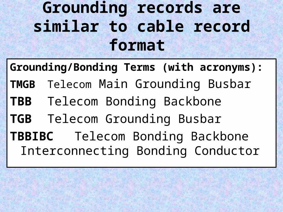
Grounding records are similar to cable record format
Grounding/Bonding Terms (with acronyms): TMGB Telecom Main Grounding Busbar TBB Telecom Bonding BackboneTGB Telecom Grounding BusbarTBBIBC Telecom Bonding Backbone
Interconnecting Bonding Conductor

Label Color Coding Termination Type Color CommentsDemarcation Point Orange CO terminations
Network Connections Green also aux. circuit terms.Common Equipment Purple PBX, Host, LANs, MuxFirst-level Backbone White MC-IC terminations
Second-level Backbone Gray IC-TC terminationsStation Blue Horizontal cable terms.
Interbuilding Backbone Brown Campus cable terms.Miscellaneous Yellow Aux., maint., security
Key Telephone Systems Red

Other Considerations include:
Summary of Records Elements Pathway & Space Administration
Wiring System Administration Grounding and Bonding Administration
Label Color Coding
ANSI/TIA/EIA-607
Commercial Building Grounding and Bonding Requirements for
Telecommunications
The Purpose of ANSI/TIA/EIA-607
This standard specifies a uniform telecommunications grounding and bonding infrastructure that shall be followed within commercial buildings.
Following the AT&T divestiture of 1984, the end-user became
responsible for all premises cabling for voice and data. Advancements in voice and data communications and the convergence of voice and data communications led to increasingly complex interactive systems owned and maintained by the end-user. These systems require a reliable electrical ground-reference potential. Grounding by attachment to the nearest piece of iron pipe is no longer satisfactory to provide ground-reference for sophisticated active electronics systems.

Design Considerations
Solid copper grounding busbars are installed with insulated standoffs in entrance facilities(1/4” thick X 4” high X variable length) and the equipment room, as well as each telecom closet (2” high is sufficient here). Each busbar is drilled with rows of holes according to NEMA standards, for attachment of bolted compression fittings.

Telecommunications equipment, frames, cabinets and voltage protectors are typically grounded to these busbars. Busbars are connected by a backbone of insulated, solid copper cable between all closets and rooms (minimum 6 AWG, 3/0 AWG recommended). This backbone is connected to a main grounding busbar in the telecommunications entrance facility, to an earth ground in the electrical entrance facility, and to structural steel on each floor. Bonding conductor cabling shall be colored green or labeled appropriately.

Terms
Telecommunications Main Grounding Busbar (TMGB) Telecom Bonding Backbone (TBB) Telecom Grounding Busbar (TGB) Telecom Bonding Backbone Interconnecting
Bonding Conductor (TBBIBC)

Schematic of Grounding/Bonding Network