DATA SHEETDATA SHEET -...
20
DATA SHEET DATA SHEET DATA SHEET DATA SHEET LCD LCD LCD LCD CONTROLLER CONTROLLER CONTROLLER CONTROLLER VIDEO VIDEO VIDEO VIDEO WALL WALL WALL WALL BOARD BOARD BOARD BOARD Preliminary Specification Model Name: MULTIVISION Note: Specification is subject to change without notice. Consequently it is better to contact to our company before proceeding with the design of your product incorporating this board. Prepared Checked Approved YH HAN
Transcript of DATA SHEETDATA SHEET -...

DATA SHEETDATA SHEETDATA SHEETDATA SHEET
LCDLCDLCDLCD CONTROLLERCONTROLLERCONTROLLERCONTROLLER VIDEOVIDEOVIDEOVIDEO WALLWALLWALLWALL BOARDBOARDBOARDBOARD
Preliminary Specification
Model Name: MULTIVISION
Note: Specification is subject to change without notice. Consequently it is better to contact to our company before proceeding with the design of your
product incorporating this board.
Prepared Checked Approved
YH HAN

MAR 25, 2010 2 HIHIHIHI----DISPLAYDISPLAYDISPLAYDISPLAY Co,. LtdCo,. LtdCo,. LtdCo,. Ltd
Datasheet
Revision History
No. Rev. Date Description of Revision.
1 V0 MAR 25, 2012 Preliminary Release

MAR 25, 2010 3 HIHIHIHI----DISPLAYDISPLAYDISPLAYDISPLAY Co,. LtdCo,. LtdCo,. LtdCo,. Ltd
Datasheet
Table of Contents
1. GENERAL DESCRIPTION ................................................................................................................................................ 4 2. INTRODUCTION ................................................................................................................................................................ 5 3. GENERAL SPECIFICATION ............................................................................................................................................ 6 4. ELECTRICAL SPECIFICATION ..................................................................................................................................... 7 4.1. INPUT CHARACTERISTIC ..................................................................................................................................................... 7 4.2. OUTPUT CHARACTERISTIC .................................................................................................................................................. 7
5. FUNCTIONAL BLOCK DIAGRAM ................................................................................................................................. 8 6. OSD CONTROL BOARD ................................................................................................................................................... 9 7. OSD FUNCTION ............................................................................................................................................................... 10 8. CONNECTOR, PINOUT & JUMPERS........................................................................................................................... 11 9. CONTROLLER DIMENSIONS ....................................................................................................................................... 15 10. APPLICATION NOTES ................................................................................................................................................ 16 11. TROUBLESHOOTING ................................................................................................................................................. 17 12. APPLICABLE GRAPHIC MODE ............................................................................................................................... 18 13. ACCESSORY ................................................................................................................................................................. 19 14. APPENDIX ..................................................................................................................................................................... 20

MAR 25, 2010 4 HIHIHIHI----DISPLAYDISPLAYDISPLAYDISPLAY Co,. LtdCo,. LtdCo,. LtdCo,. Ltd
Datasheet
1. GENERAL DESCRIPTION This controller board is designed for a LCD monitor and other flat panel display application. This controller board provides an auto-input synchronization and easy to sue interface controller for:
� TFT (active matrix) LCD panels of 800x480, 1024x768, 1024x768, 1280x768, 1366x768, 1280x1024 1440x900 and 1600x1200, 1680x1050, 1920x1080 resolutions.
� Computer video signals of VGA, SVGA, XGA, SXGA and WUXGA standard Input Signal Support � All VESA standard
[[[[MULTIVISIONMULTIVISIONMULTIVISIONMULTIVISION]]]]

MAR 25, 2010 5 HIHIHIHI----DISPLAYDISPLAYDISPLAYDISPLAY Co,. LtdCo,. LtdCo,. LtdCo,. Ltd
Datasheet
2. INTRODUCTION HOW TO PROCEED
� Ensure that you have all parts & they are correct, refer to: � Connection diagram
� Check controller switch & jumper settings (errors may damage the panel) � Prepare the PC � Connect the parts � Understand the operation & functions
* Since LSI is used in this controller board, take care of static electricity and insure human earth when handling.
IMPORTANT USAGE NOTE This equipment is for use by developers and integrators. The manufacturer accepts no liability for damage or injury caused by the use of this product. It is the responsibility of the developer, integrators or other users of this product to:
� Ensure that all necessary and appropriate safety measures are taken. � Obtain suitable regulatory approvals as may be required. � Check power settings to all component parts before connection.
DISCLAIMER There is no implied or expressed warranty regarding this material.

MAR 25, 2010 6 HIHIHIHI----DISPLAYDISPLAYDISPLAYDISPLAY Co,. LtdCo,. LtdCo,. LtdCo,. Ltd
Datasheet
3. GENERAL SPECIFICATION
No. Item Description
1 Model name MULTIVISION
2 LCD Module LVDS MIN – 800X600 ~ MAX - 1920X1080
3 Input Analog RGB I/O, DVI-D(TMDS) I/O, HDMI(TMDS) I/O
CVBS I/O, COMPONENTI/O, RS232 I/O, AUDIO
4 Resolution
Support
H: 31 ∼ 80kHz
V: 55 ∼ 76Hz
5 OSD Control Input, Menu, Left, Right, Down, Up, Power 7 keys
Plug & Play VESA DDC 2B Ver1.3
6 Power Consumption Supply Voltage 12Vdc
Max Power TBD
7 Signal Connector
Analog DSUB 15P(R, G, B Separate H, V Sync)
Digital DVI-D (TMDS)
Digital HDMI 1.3ª (TMDS)
Video MINIDIN-4P(RCA-CVBS,COMPONENT)
Audio 5W * 5W
8 Board Size W x H x D(mm) 295 x 150 x 35

MAR 25, 2010 7 HIHIHIHI----DISPLAYDISPLAYDISPLAYDISPLAY Co,. LtdCo,. LtdCo,. LtdCo,. Ltd
Datasheet
4. ELECTRICAL SPECIFICATION 4.1. Input characteristic
Description Signal Unit Min Typical Max Remarks
Power In (12Vdc)
Input 12VDC 11.4 12 12.6
Consumption Watt TBD
RGB Input
Analog RGB VPP 0 0.7 -
Sync VDC 0 5 5.5
H Frequency KHz 31 80 Depends on Mode
V Frequency Hz 55 75 77 Depends on Mode
DVI Input
TMDS mVp-p 450 500 900
NTSC/PAL
Y/CVBS Vp-p 0.7 1.0 1.4
C Vp-p 0.6 0.8 1.0
COMPONENT
Y Vp-p 1.0
PB/PR Vp-p 0.7
INPUT FORMAT 480 i 1080p
4.2. Output characteristic
Description Signal Unit Min Typical Max Remarks
Panel Power
LCD Power (12V)
VDC 11.4 12 12.6 Jumper option
LCD Power (5V)
VDC 4.5 5 5.5 Jumper option
LCD Power (3.3V)
VDC 3.16 3.3 3.5 Jumper option
LVDS Interface
Differential output
Vp-p (mV) 250 350 450 Differential +/-
AUDIO Interface
Output Watt 5 6
Frequence Hz 700Hz 20KHz
THD 5% MAX AT 1500Hz 1.0W
Inverter Interface
Power V 11.4 12 12.6 Depends on Power
On/Off control V 0 3.3 L=off, H=on
Brightness control
V 3.3 0 Option
0 4.0 Option

MAR 25, 2010 8 HIHIHIHI----DISPLAYDISPLAYDISPLAYDISPLAY Co,. LtdCo,. LtdCo,. LtdCo,. Ltd
Datasheet
5. FUNCTIONAL BLOCK DIAGRAM
SCALERSCALERSCALERSCALER
LLLLVVVVDDDDS S S S OOOOUUUUTTTTPPPPUUUU
DC to DC to DC to DC to DCDCDCDC ConvConvConvConvertererterertererter
EEPEEPEEPEEPROROROROMMMM
AUDIOAUDIOAUDIOAUDIO ICICICIC
OOOOSSSSD D D D I/I/I/I/FFFF
3.3V3.3V3.3V3.3V
2.5V2.5V2.5V2.5V 1.2V1.2V1.2V1.2V
FlashFlashFlashFlash
MEMORYMEMORYMEMORYMEMORY
HHHHDDDDMMMMIIII HHHHDDDDMMMMIIII
RS232RS232RS232RS232
DC to DC to DC to DC to DCDCDCDC ConvConvConvConvertererterertererter
DC to DC to DC to DC to DCDCDCDC ConvConvConvConvertererterertererter
DC to DC to DC to DC to DCDCDCDC ConvConvConvConvertererterertererter
TMDSTMDSTMDSTMDS 341341341341
TMDSTMDSTMDSTMDS 341341341341
DVI 1DVI 1DVI 1DVI 1ch INPUTch INPUTch INPUTch INPUT (OPTION)(OPTION)(OPTION)(OPTION)
DVIDVIDVIDVI IN/OUTIN/OUTIN/OUTIN/OUT
HDMIHDMIHDMIHDMI IN/OUTIN/OUTIN/OUTIN/OUT
RGBRGBRGBRGB IN/OUTIN/OUTIN/OUTIN/OUT
YPBPRYPBPRYPBPRYPBPR IN/OUTIN/OUTIN/OUTIN/OUT
AVAVAVAV IN/OUTIN/OUTIN/OUTIN/OUT

MAR 25, 2010 9 HIHIHIHI----DISPLAYDISPLAYDISPLAYDISPLAY Co,. LtdCo,. LtdCo,. LtdCo,. Ltd
Datasheet
6. OSD Control Board The OSD (On Screen Display) provides certain functions to have clear image and others. This board supports 5 buttons OSD operation as a standard. The control functions defined on OSD operation are as below. (Unit: mm) Appearance INPUT INPUT INPUT INPUT MENU MENU MENU MENU LEFT RIGHTLEFT RIGHTLEFT RIGHTLEFT RIGHT DOWN DOWN DOWN DOWN UP LED UP LED UP LED UP LED POWERPOWERPOWERPOWER
Board Size (W x H x D) : 11Board Size (W x H x D) : 11Board Size (W x H x D) : 11Board Size (W x H x D) : 110 x 150 x 150 x 150 x 15x 10mmx 10mmx 10mmx 10mm
Button Function Status HOT Key
LED Indicates operation status Green/ Red/ Amber On: Green Off: Red
No Signal: Amber
POWER Power on/off On/Off
MENU Activate menu / Exit Menu
INPUT Input Select / Source
LEFT Cursor control Left
RIGHT Cursor control Right
DOWN Cursor control Down
UP Cursor control Up / Auto Adjust
5.0
1.6 3

MAR 25, 2010 10 HIHIHIHI----DISPLAYDISPLAYDISPLAYDISPLAY Co,. LtdCo,. LtdCo,. LtdCo,. Ltd
Datasheet
7. OSD FUNCTION
A.A.A.A. Main MenuMain MenuMain MenuMain Menu
� Picture(VGA) : Brightness/Contrast/Color Mode
Scale/Auto - Brightness: Brightness level Control - Contrast : Contrast level Control - Color Mode - Scale - Auto -
� Picture(Video) : Contrast/Brightness/ Hue/Saturation/Sharpness/ Scale/Color System
- Contrast: Contrast level Control - Brightness: Brightness level Control - Hue: Hue level Control - Saturation : Saturation level Control - Sharpness: Sharpness level Control - Scale : Display Ratio Select - Color System
� Geometry H,V. Position / Clock Phase
- H/V position: Image H, V position Control - Clock: Fine tune the number of sampled
data - Phase: Fine tune the position of sampled
data
� System : Sleep, Language, OSD H/V, OSD Timer, Sleep, OSD Blending, Information, Recall
- Language - OSD Timer - Sleep - OSD Blending - Set ID - H Count - V Count - H Position - V Position - Recall
� MultiMultiMultiMulti VisionVisionVisionVision MenuMenuMenuMenu

MAR 25, 2010 11 HIHIHIHI----DISPLAYDISPLAYDISPLAYDISPLAY Co,. LtdCo,. LtdCo,. LtdCo,. Ltd
Datasheet
8. CONNECTOR, PINOUT & JUMPERS The various connectors
Summary:
Item Description Type Manufacture
Connector Audio Connector CKX3-3.5-11 -
Connector Audio Output Connector SMW200-04P-2.0mm YEONHO
Connector LVDS Dual Interface Connector 12507WR-30P YEONHO
Connector OSD Connector 12505WR-12P YEONHO
Connector Inverter Connector SMW200-08P-2.0mm YEONHO
Connector 12V Dc power Input SMW200-04P-2.0mm YEONHO
Jack Dc power Jack 2.5ø DC Jack -
Jack Panel Power H-3x2-6p
CN14: Audio Output Connector
Pin No. Symbol Description
1 L AUDIO L
2 GND Ground
3 GND Ground
4 R AUDIO R
HDHDHDHDMIMIMIMI L-I, R-O
JJJJ20202020 SMPS
OSD KEY INVERTER AUDIO OUTPUT
RS232RS232RS232RS232 U-O, D-I
DVIDVIDVIDVI U-D, D-I
RGBRGBRGBRGB U-O D-I
AUDIO INTPUT
LVDS CN
VIDEOVIDEOVIDEOVIDEO L-I , R-O
YPBPRYPBPRYPBPRYPBPR U-O, D-I

MAR 25, 2010 12 HIHIHIHI----DISPLAYDISPLAYDISPLAYDISPLAY Co,. LtdCo,. LtdCo,. LtdCo,. Ltd
Datasheet
J3: LVDS Dual Interface Connector
Pin No. Symbol Description
1 MOD_PWR Panel Power (12V/18V, 5V or 3.3V)
2 MOD_PWR Panel Power (12V/18V, 5V or 3.3V)
3 MOD_PWR Panel Power (12V/18V, 5V or 3.3V)
4 N.C No Connection
5 N.C No Connection
6 N.C No Connection
7 GND Ground
8 Y3P-EVEN Positive(+) LVDS differential first 3 data(B port)
9 Y3M-EVEN Negative(-) LVDS differential first 3 data(B port)
10 YCP-EVEN Positive(+) LVDS differential first Clock(B port)
11 YCM-EVEN Negative(-) LVDS differential first Clock(B port)
12 Y2P-EVEN Positive(+) LVDS differential first 2 data(B port)
13 Y2M-EVEN Negative(-) LVDS differential first 2 data(B port)
14 GND Ground
15 Y1P-EVEN Positive(+) LVDS differential first 1 data(B port)
16 Y1M-EVEN Negative(-) LVDS differential first 1 data(B port)
17 GND Ground
18 YOP-EVEN Positive(+) LVDS differential first 0 data(B port)
19 Y0M-EVEN Negative(-) LVDS differential first 0 data(B port)
20 Y3P-ODD Positive(+) LVDS differential second 3 data(A port)
21 Y3M-ODD Negative(-) LVDS differential second 3 data(A port)
22 YCP-ODD Positive(+) LVDS differential second Clock(A port)
23 YCM-ODD Negative(-) LVDS differential second Clock(A port)
24 GND Ground
25 Y2P-ODD Positive(+) LVDS differential second 2 data(A port)
26 Y2M-ODD Negative(-) LVDS differential second 2 data(A port)
27 Y1P-ODD Positive(+) LVDS differential second 1 data(A port)
28 Y1M-ODD Negative(-) LVDS differential second 1 data(A port)
29 YOP-ODD Positive(+) LVDS differential second 0 data(A port)
30 Y0M-ODD Negative(-) LVDS differential second 0 data(A port)
* You can use an even port for 1Ch LVDS CN11: OSD Connector
Pin No. Symbol Description
1 LED-Green GREEN Color
2 LED-Red RED Color
3 GND Ground
4 AUTO For Auto Switch
5 MENU For Menu Switch
6 SEL For Select Switch
7 DOWN For Down Switch
8 UP For Up Switch
9 POWER For Power Switch
10 CDS For Auto Brightness (Option)
11 IRD IR DATA
12 5V IR POWER 5V

MAR 25, 2010 13 HIHIHIHI----DISPLAYDISPLAYDISPLAYDISPLAY Co,. LtdCo,. LtdCo,. LtdCo,. Ltd
Datasheet
CN5: Backlight Inverter connector
Pin No. Symbol Description
1, 2 VCC 12V
3.4 GND Ground
5 ON/OFF Inverter digital ON(3.3V)/OFF(0V) signal
6 ADJ(PWM) DIM-adjustment analog dimming control signal * make sure inverter specification
J28: SMPS Power input connector
Pin No. Symbol Description
1,2 VCC 12V
3,4 GND Ground
CN1: ANALOG RGB INPUT (D-Sub 15P)
Pin No. Symbol Description
1 Red1 Red analog input
2 Green1 Green analog input
3 Blue1 Blue analog input
4 GND Ground
5 GND Ground
6 GND Ground
7 GND Ground
8 GND Ground
9 NC Not connected
10 GND Ground
11 GND Ground
12 DSDA DDC-SDA
13 HSYNC Horizontal Sync
14 VSYNC Vertical Sync
15 DSCL Serial Clock Input
J25: DC power Input Jack(12V)
Pin No. Symbol Description Pin No. Symbol Description
Center Vcc 12V Shell GND Ground

MAR 25, 2010 14 HIHIHIHI----DISPLAYDISPLAYDISPLAYDISPLAY Co,. LtdCo,. LtdCo,. LtdCo,. Ltd
Datasheet
Summary: Panel Power setting
Reference Description Connector Type
RP1 3.3V panel power CAUTION: Incorrect setting can
damage panel
5.0V panel power CAUTION: Incorrect setting can
damage panel
12V/18V panel power CAUTION: Incorrect setting can
damage panel
CAUTION: Incorrect setting can damage panel
3.3V 12V 5V
3.3V 12V 5V
3.3V 12V 5V

MAR 25, 2010 15 HIHIHIHI----DISPLAYDISPLAYDISPLAYDISPLAY Co,. LtdCo,. LtdCo,. LtdCo,. Ltd
Datasheet
9. CONTROLLER DIMENSIONS

MAR 25, 2010 16 HIHIHIHI----DISPLAYDISPLAYDISPLAYDISPLAY Co,. LtdCo,. LtdCo,. LtdCo,. Ltd
Datasheet
10. APPLICATION NOTES A. A. A. A. USING THE CONTROLLER WITHOUT BOTTONS ATTACHEDUSING THE CONTROLLER WITHOUT BOTTONS ATTACHEDUSING THE CONTROLLER WITHOUT BOTTONS ATTACHEDUSING THE CONTROLLER WITHOUT BOTTONS ATTACHED:::: This is very straightforward:
� Firstly setup the controller/display system with the buttons. With the attached controllers and display system active make any settings for color, contrast and image position as required then switch everything off.
� Remove the control switches, the 7-way cable. � Refer to inverter specifications for details as to fixing brightness to a desired level, this may require a
resistor, an open circuit or closed circuit depending on inverter B. B. B. B. INVERTER CONNECTIONINVERTER CONNECTIONINVERTER CONNECTIONINVERTER CONNECTION:::: There are 3 potential issues to consider with inverter connection:
� Power � ON/OFF � Brightness (DIM-ADJ)
Inverter power: This should be matched with the inverter specification. Inverter ON/OFF: This is a pin provided on some inverter for ON/OFF function and is used by this panel controller for VESA DPMS compliance. If the inverter does not have on/off pin or the on/off pin is not used DPMS will not operate.Pin5 should be matched to the inverter specification for the ON/OFF pin. Brightness Dimming control: This controller boards are analog dimming control method. And it is important to consider the specifications for the inverter to be used.

MAR 25, 2010 17 HIHIHIHI----DISPLAYDISPLAYDISPLAYDISPLAY Co,. LtdCo,. LtdCo,. LtdCo,. Ltd
Datasheet
11. TROUBLESHOOTING A. A. A. A. GeneralGeneralGeneralGeneral:::: A general guide to troubleshooting of a flat panel display system it worth considering the system as separate elements, such as:
� Controller (jumpers, PC settings) � Panel (controller, cabling, connection, panel, PC settings) � Backlight (inverter, cabling, connection, panel, Pc settings) � Cabling � Computer system (display settings, operating system)
Through checking the system step by step cross with instruction manuals and a process of elimination to isolate the problem it is usually possible to clearly identify the problem area. B. B. B. B. No image:No image:No image:No image:
� If the panel backlight is not working it may still be possible to see just some image. � A lack of image is most likely to be caused by incorrect connection, lack of power, failure to provide a
signal or incorrect graphic card settings. C. C. C. C. Image position:Image position:Image position:Image position: If it is impossible to position the image correctly, the image adjustment controls will not move the image far enough, then test using another graphics card. This situation can occur when a graphic card is not close to standard timing or when something is in the graphics line that may affect the signal such as a signal splitter (please note that normally a signal splitter will not have any adverse effect). D. D. D. D. Image appearance:Image appearance:Image appearance:Image appearance:
� A faulty panel can have blank lines, failed sections, flickering or flashing display. � Incorrect graphic card refresh rate, resolution or interlaced mode will probably cause the image to be the
wrong size, to scroll to, flicker badly or possibly even no image. � Incorrect jumper settings on the controller may cause everything from incorrect image viewing to total
failure. CAUTION: Do not set the panel power input incorrectly.
� Sparkling on the display: faulty panel signal cable.
E. E. E. E. Backlight:Backlight:Backlight:Backlight::::: Items to check include: Power input, controls, inverter and Tubes generally in this order. If half the screen is dimmer than the other half:
� Check cabling for the inverter. � Also: If system does not power down when there is a loss of signal.

MAR 25, 2010 18 HIHIHIHI----DISPLAYDISPLAYDISPLAYDISPLAY Co,. LtdCo,. LtdCo,. LtdCo,. Ltd
Datasheet
12. APPLICABLE GRAPHIC MODE The microprocessor measures the, H – sync V – sync and polarity for RGB Inputs, and uses this timing information to control all of the display operation to get the proper image on a screen. This board can detect all VESA standard Graphic modes shown on the table below and Provide mare clear and stable image on a screen
RGB input format
Spec
Mode
Pixel Freq.
Horizontal Timing Vertical Timing Sync Polar
Freq. Active Sync Polar
Freq. Active
MHz KHz Pixel Hz Lind
640*350@70Hz 25.144 P 31.430 640 N 70.000 350
640*400@70Hz 28.287 N 31.430 640 P 70.000 400
720*400@ 70Hz 28.287 N 31.430 720 P 70.000 400
640*480@60Hz 28.175 N 31.469 640 N 59.940 480
640*480@72Hz 31.500 N 37.861 640 N 72.809 480
640*480@75Hz 31.500 N 37.500 640 N 75.000 480
800*600@56 Hz 36.000 P 35.156 800 P 56.250 600
800*600@60Hz 40.000 P 37.879 800 P 60.317 600
800*600@72Hz 50.000 P 48.077 800 P 72.188 600
800*600@75Hz 49.500 P 46.875 800 P 75.000 600
1024*768@60Hz 65.000 N 48.363 1024 N 60.005 768
1024*768@ 70Hz 75.000 N 56.476 1024 P 70.070 768
1024*768@75Hz 78.750 P 60.023 1024 P 75.030 768
1280*720@60Hz 74.500 P 44.772 1280 P 59.855 720
1366*768@60Hz 84.75 P 47.72 1366 P 59.799 768
1440*900@60Hz 106.500 N 55.935 1440 P 59.887 900
1280*1024@60Hz 108.000 P 63.981 1280 P 60.020 1024
1280*1024@75Hz 135.000 P 79.976 1280 P 75.035 1024
1600*1200@60Hz 162.000 P 75.000 1600 p 60.000 1200
1680*1050@60Hz 119.000 P 64.674 1680 N 59.883 1050
1920*1080@60Hz 138.500 P 66.587 1920 N 59.934 1080

MAR 25, 2010 19 HIHIHIHI----DISPLAYDISPLAYDISPLAYDISPLAY Co,. LtdCo,. LtdCo,. LtdCo,. Ltd
Datasheet
13. ACCESSORY This controller board requires several accessories to build a complete display unit. We can provide standard accessory for this board as below.
No. Items Part No. Ex) LG. Philips LP121S1
1 LCD I/F cable
2 Inverter
3 Inverter Cable
4 OSD Board
5 OSD Cable
MAR 25, 2010 20 HIHIHIHI----DISPLAYDISPLAYDISPLAYDISPLAY Co,. LtdCo,. LtdCo,. LtdCo,. Ltd
Datasheet
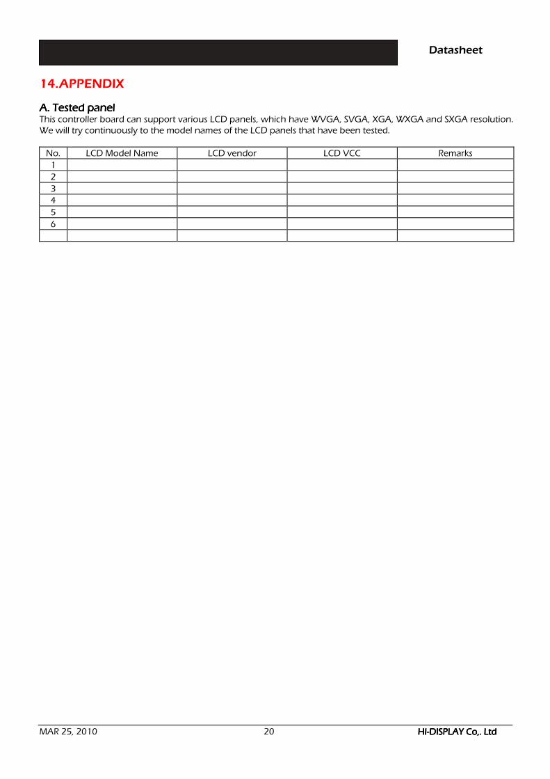
14. APPENDIX A. Tested panelA. Tested panelA. Tested panelA. Tested panel This controller board can support various LCD panels, which have WVGA, SVGA, XGA, WXGA and SXGA resolution. We will try continuously to the model names of the LCD panels that have been tested.
No. LCD Model Name LCD vendor LCD VCC Remarks
1
2
3
4
5
6