DATA SHEET - sdme.customer.ipower.besdme.customer.ipower.be/images/upload/File/Datasheet...
30
DEIF A/S · Frisenborgvej 33 · DK-7800 Skive Tel.: +45 9614 9614 · Fax: +45 9614 9615 [email protected] · www.deif.com DATA SHEET Automatic Genset Controller, AGC-4 ● Single or synchronising gensets ● Power plant control ● Fast synchronising ● Control and protection ● Customised logic and control ● SW emulation of application Document no.: 4921240400J SW version: 4.3x.x or later
Transcript of DATA SHEET - sdme.customer.ipower.besdme.customer.ipower.be/images/upload/File/Datasheet...

DEIF A/S · Frisenborgvej 33 · DK-7800 Skive · Tel.: +45 9614 9614 · Fax: +45 9614 9615 · [email protected] · www.deif.com
DEIF A/S · Frisenborgvej 33 · DK-7800 Skive · Tel.: +45 9614 9614 · Fax: +45 9614 9615 · [email protected] · www.deif.com
DEIF A/S · Frisenborgvej 33 · DK-7800 Skive · Tel.: +45 9614 9614 · Fax: +45 9614 9615 · [email protected] · www.deif.com
DATA SHEET
Automatic Genset Controller, AGC-4● Single or synchronising gensets● Power plant control● Fast synchronising● Control and protection● Customised logic and control● SW emulation of application
Document no.: 4921240400JSW version: 4.3x.x or later

1. Application information1.1. General information................................................................................................................................3
1.1.1. Application.....................................................................................................................................31.1.2. Application emulation.....................................................................................................................31.1.3. Inputs and outputs.........................................................................................................................41.1.4. Included functions..........................................................................................................................51.1.5. Protections.....................................................................................................................................71.1.6. Single line application diagrams....................................................................................................81.1.7. Terminal overview .......................................................................................................................10
1.2. Power management applications.........................................................................................................111.2.1. Application...................................................................................................................................111.2.2. Description...................................................................................................................................111.2.3. Power management functions.....................................................................................................121.2.4. Easy configuration of single line diagrams..................................................................................131.2.5. Safe power management system................................................................................................131.2.6. Optional power management applications ..................................................................................14
2. Optional functionality2.1. Display layouts.....................................................................................................................................16
2.1.1. Option Y1 ....................................................................................................................................162.1.2. Option Y3 ....................................................................................................................................162.1.3. Option Y4.....................................................................................................................................162.1.4. Option Y5.....................................................................................................................................172.1.5. Option X3 ....................................................................................................................................172.1.6. Option X4 ....................................................................................................................................17
2.2. Available options..................................................................................................................................182.2.1. Available variants ........................................................................................................................182.2.2. Available software options...........................................................................................................192.2.3. Available accessories..................................................................................................................212.2.4. Hardware options and slot number location................................................................................22
3. Technical information3.1. Specifications and dimensions.............................................................................................................25
3.1.1. Technical specifications ..............................................................................................................253.1.2. Unit dimensions in mm (inches)...................................................................................................29
4. Ordering information4.1. Order specifications and disclaimer.....................................................................................................30
4.1.1. Order specifications.....................................................................................................................304.1.2. Disclaimer....................................................................................................................................30
AGC-4 data sheet 4921240400 UK
DEIF A/S Page 2 of 30
1. Application information1.1 General information
1.1.1 ApplicationThe Automatic Genset Controller, AGC, is a control unit containing all necessary functions for protection andcontrol of a genset. It can be used as a single unit for one genset, or a number of AGCs can be connected ina complete power management system for synchronising projects, islanded or paralleled to the mains. TheAGC contains all necessary 3-phase measuring circuits, and all values and alarms are presented on the sun-shine proof LCD display.
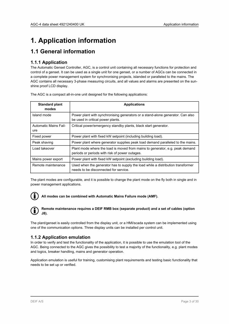
The AGC is a compact all-in-one unit designed for the following applications:
Standard plantmodes
Applications
Island mode Power plant with synchronising generators or a stand-alone generator. Can alsobe used in critical power plants.
Automatic Mains Fail-ure
Critical power/emergency standby plants, black start generator.
Fixed power Power plant with fixed kW setpoint (including building load).
Peak shaving Power plant where generator supplies peak load demand paralleled to the mains.
Load takeover Plant mode where the load is moved from mains to generator, e.g. peak demandperiods or periods with risk of power outages.
Mains power export Power plant with fixed kW setpoint (excluding building load).
Remote maintenance Used when the generator has to supply the load while a distribution transformerneeds to be disconnected for service.
The plant modes are configurable, and it is possible to change the plant mode on the fly both in single and inpower management applications.
All modes can be combined with Automatic Mains Failure mode (AMF).
Remote maintenance requires a DEIF RMB box (separate product) and a set of cables (optionJ8).
The plant/genset is easily controlled from the display unit, or a HMI/scada system can be implemented usingone of the communication options. Three display units can be installed per control unit.
1.1.2 Application emulationIn order to verify and test the functionality of the application, it is possible to use the emulation tool of theAGC. Being connected to the AGC gives the possibility to test a majority of the functionality, e.g. plant modesand logics, breaker handling, mains and generator operation.
Application emulation is useful for training, customising plant requirements and testing basic functionality thatneeds to be set up or verified.
AGC-4 data sheet 4921240400 UK Application information
DEIF A/S Page 3 of 30
In a power management system it is possible to control the entire plant, being connected only to one of theconnected AGC controllers.
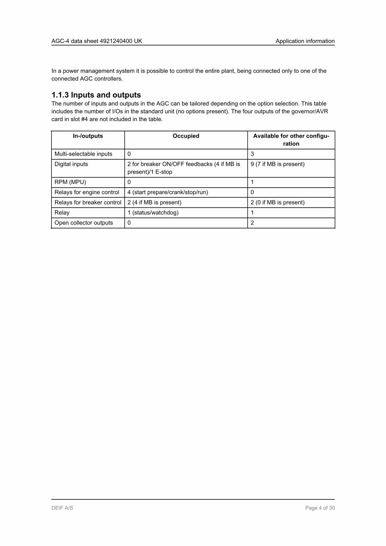
1.1.3 Inputs and outputsThe number of inputs and outputs in the AGC can be tailored depending on the option selection. This tableincludes the number of I/Os in the standard unit (no options present). The four outputs of the governor/AVRcard in slot #4 are not included in the table.
In-/outputs Occupied Available for other configu-ration
Multi-selectable inputs 0 3
Digital inputs 2 for breaker ON/OFF feedbacks (4 if MB ispresent)/1 E-stop
9 (7 if MB is present)
RPM (MPU) 0 1
Relays for engine control 4 (start prepare/crank/stop/run) 0
Relays for breaker control 2 (4 if MB is present) 2 (0 if MB is present)
Relay 1 (status/watchdog) 1
Open collector outputs 0 2
AGC-4 data sheet 4921240400 UK Application information
DEIF A/S Page 4 of 30
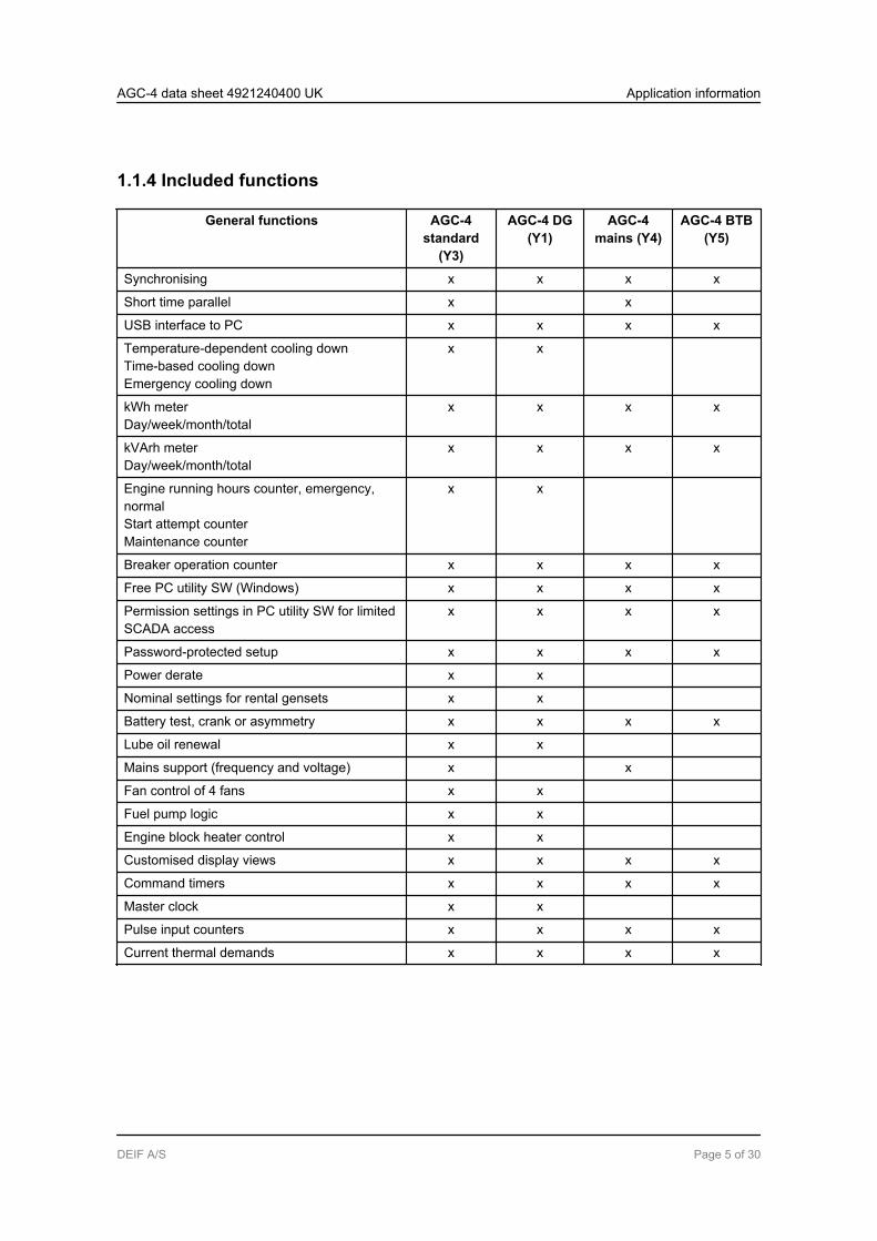
1.1.4 Included functions
General functions AGC-4standard
(Y3)
AGC-4 DG(Y1)
AGC-4mains (Y4)
AGC-4 BTB(Y5)
Synchronising x x x x
Short time parallel x x
USB interface to PC x x x x
Temperature-dependent cooling downTime-based cooling downEmergency cooling down
x x
kWh meterDay/week/month/total
x x x x
kVArh meterDay/week/month/total
x x x x
Engine running hours counter, emergency,normalStart attempt counterMaintenance counter
x x
Breaker operation counter x x x x
Free PC utility SW (Windows) x x x x
Permission settings in PC utility SW for limitedSCADA access
x x x x
Password-protected setup x x x x
Power derate x x
Nominal settings for rental gensets x x
Battery test, crank or asymmetry x x x x
Lube oil renewal x x
Mains support (frequency and voltage) x x
Fan control of 4 fans x x
Fuel pump logic x x
Engine block heater control x x
Customised display views x x x x
Command timers x x x x
Master clock x x
Pulse input counters x x x x
Current thermal demands x x x x
AGC-4 data sheet 4921240400 UK Application information
DEIF A/S Page 5 of 30

Control functions AGC-4standard
(Y3)
AGC-4 DG(Y1)
AGC-4mains (Y4)
AGC-4 BTB(Y5)
Start/stop sequences x x
Synchronising x x x x
Close before excitation (fast synchro.) x x
Nos. of breakers/contactors to be controlled 2 1 2/1 1
Run coil x x
Stop coil with wire break x x
Relay outputs for speed control x x
Event log with real-time clockAlarm log with real-time clockBattery crank test log with real-time clock
x x x x
M-Logic AGC-4standard
(Y3)
AGC-4 DG(Y1)
AGC-4mains (Y4)
AGC-4 BTB(Y5)
Logic configuration tool for plant customis-ing
x x x x
Selectable input events, e.g. plant status x x x x
Selectable output events, e.g. plant com-mands
x x x x
AGC-4 data sheet 4921240400 UK Application information
DEIF A/S Page 6 of 30

1.1.5 Protections
Protections No. of ANSI AGC-4standard
(Y3)
AGC-4 DG(Y1)
AGC-4mains (Y4)
AGC-4BTB (Y5)
Reverse power x2 32R x x x
Short circuit x2 50P x x x
Overcurrent x4 51 x x x x
Voltage-dependent overcurrent x1 51V x x x x
Overvoltage x2 59P x x x
Undervoltage x3 27P x x x
Overfrequency x3 81O x x x
Underfrequency x3 81U x x x
Unbalanced voltage x1 47 x x x x
Unbalanced current x1 46 x x x x
Underexcitation or VAr import x1 32RV x x x x
Overexcitation or VAr import x1 32FV x x x x
Overload x5 32F x x x x
Busbar/mains overvoltage x3 59P x x x x
Busbar/mains undervoltage x4 27P x x x x
Load shed, three levelsvia currentvia busbar frequencyvia overloadvia fast overload
x3x3x3x3
51813232
xxxx
xxxx
xxxx
Busbar/mains overfrequency x3 81O x x x x
Multi-config. inputs with wirebreak alarms, three inputs
x2 NA x x x x
Emergency stop x1 1 x x
Overspeed x2 12 x x
Low auxiliary supply x1 27DC x x x x
High auxiliary supply x1 59DC x x x x
Generator breaker external trip x1 5 x x
Tie/mains breaker external trip x1 5 x x x
Synchronisation failure alarms 25 x x x x
Breaker open failure 52BF x x x x
Breaker close failure 52BF x x x x
Breaker position failure 52BF x x x x
Close before excitation failure x1 48 x x
AGC-4 data sheet 4921240400 UK Application information
DEIF A/S Page 7 of 30

Protections No. of ANSI AGC-4standard
(Y3)
AGC-4 DG(Y1)
AGC-4mains (Y4)
AGC-4BTB (Y5)
Phase sequence error x1 47 x x x x
Deload error x1 34 x x
Crank failure x1 48 x x
Running feedback error x1 34 x x
MPU wire break x1 NA x x
Start failure x1 48 x x
Hz/V failure x1 53 x x
Stop failure x1 48 x x
Stop coil, wire break alarm x1 5 x x
Engine heater x1 26 x x
Battery test alarm x1 NA x x
Max. ventilation/radiator fan x2 NA x x x x
Not in Auto x1 34 x x x x
Fuel fill check x1 NA x x
1.1.6 Single line application diagrams
Standard, 1 controller
1. Automatic mains failure andfixed power/base load
2. Island 3. Peak shaving, load takeoverand mains power export
G
Generator
breaker
(GB)
Mains
breaker
(MB)
Mains
Diesel generator set
Consumers
Controller
Display
G
Generator
breaker
(GB)
Diesel generator set
Busbar
Controller
Display
G
Generator
breaker
(GB)
Mains
breaker
(MB)
Mains
Diesel generator set
Consumers
Transducer(TAS-331DG)
Controller
Display
AGC-4 data sheet 4921240400 UK Application information
DEIF A/S Page 8 of 30

Optional
4. Multiple gensets, load sharing (1 controller per genset) 5.-9. Power managment
G
Generator
breaker
(GB 1)
Diesel generator set 1
Busbar
G
Generator
breaker
(GB 2)
Diesel generator set 2
Analogue
loadsharing
Controller
Display 1
Controller
Display 2 See separate page in this datasheet
AGC-4 data sheet 4921240400 UK Application information
DEIF A/S Page 9 of 30

1.1.7 Terminal overviewThis terminal strip overview shows the terminals of an AGC with commonly used HW options. The diagrammight not reflect your actual unit due to different option configuration.
34
56
7
STATUS
HORN
28
73
74
75
76
77
78
79
80
81
82
83
84
85
86
87
88
89
G
L1
L2
L3
NM
UL
TI IN
PU
TS
1021
02
10
31
04
105
10
51
06
10
7
108
10
81
09
11
01
19
12
01
21
12
21
23
12
4
PREPARE
RUN
CRANK
STOP
COIL
11
11
12
11
31
14
11
51
16
11
71
18
E-STOP
12
61
27
12
81
29
13
01
31
13
21
33
OP
TIO
N M
13
.8O
PT
ION
H2
/H3/H
8.2
35
36
29
31
33
30
32
34
A1
A3
B2
A2
B1
B3
CA
N A
CA
N B
MP
U
10
01
01
98
99
+-
COMMON FOR
E-STOP
12
PO
WE
R+
-
TR
AN
SIS
TO
R
OU
TP
UT
S
(MA
X 1
0 m
A)
OP
TIO
N M
12
90
92
94
96
91
93
95
97
89
10
MB OFF
23
25
27
24
26
MB OFF
MB ON
GB ON
GB OFF
43
45
47
44
46
48
50
52
49
51
53
55
54
56
11
12
13
MB ON
14
15
16
GB OFF
65
66
67
68
69
70
71
72
mA
OU
Tm
A O
UT
+ -
+ -
PID
PIDOP
TIO
N E
1
OP
TIO
N M
14
.6
CA
Nb
us
Mo
db
us
Pro
fib
us
17
18
19
GB ON
20
21
22
57
59
61
63
58
60
62
64
37
39
41
38
40
42
LO
AD
SH
AR
ING
±1
0 V
DCU/kvar
COM
COM
kW SHARE
kvar SHARE
Hz/kW
OP
TIO
N M
12/G
3
OP
TIO
N M
12
EX
T S
ET
AGC-4 data sheet 4921240400 UK Application information
DEIF A/S Page 10 of 30

1.2 Power management applicationsThe purpose of the power management system is to implement one control system that controls all breakersand all gensets. This can for instance be for fuel optimised purposes, for easy implementation of plant logic orfor safety reasons.
1.2.1 ApplicationThe plant modes supported by the power management options are:
Standard plantmodes
Applications
Island mode Power plant with synchronising generators or a stand-alone generator. Can alsobe used in critical power plants with a start signal from an external (ATS) control-ler
Automatic Mains Fail-ure
Critical power/emergency standby plants, black start generator
Fixed power Power plant with fixed kW setpoint (including building load)
Peak shaving Power plant where generator supplies peak demand
Load takeover Plant mode where the load is moved from mains to generator, e.g. peak demandperiods or periods with risk of power outages
Mains power export Power plant with fixed kW setpoint (excluding building load)
The plant modes are configurable, and it is possible to change the plant mode on the fly both in single and inpower management applications.
The plant can be divided by one to eight bus tie breakers making it possible to run the plant with differentplant modes, e.g. for test purposes or when splitting up the load in primary and secondary loads.
1.2.2 DescriptionThe AGC can be equipped with a power management option (G4, G5, G7 or G8). Using this possibility, theAGC will be able to handle simple or advanced applications for a great number of power plant projects withinsynchronising gensets, critical power/emergency standby applications or power producing applications.
The following number of units can be controlled:
● 16 mains feeders with mains and tie breaker● 8 bus tie breakers on the generator bus or load bus● 16 generators (256 in plant management applications) with generator breakers
The complete power management system can easily be monitored from the PC utility SW through a graphicalsupervision page. Running status, hours in operation, breaker status, condition of mains and busbars and fuelconsumption are just some of the values that are presented.
AGC-4 data sheet 4921240400 UK Application information
DEIF A/S Page 11 of 30

1.2.3 Power management functions
PM functions AGC-4 DG AGC-4 mains AGC-4 BTB
Multi-master system x x x
Redundant CANbus x x x
Short-time parallel (in same controller (MB/TB)) x
Load-dependent start/stop x
Priority selection, manual and automaticRunning hoursLoad profileManualFuel optimised
x
Ground relay x
ATS control x
Safety stop of DG x
Load management x x x
Secured mode (start one extra generator) x
Quick setup for rental groups x x
Heavy consumer control/generator request x
Asymmetric LS for optimal generator load level x
Plant PF control x
Mains feeder control, feeders paralleled x
Mains feeder control, main-tie-main for critical power x
Base load running for maintenance (island plants) x
Analogue load sharing for back-up with option G3 x
Section power control x
AGC-4 data sheet 4921240400 UK Application information
DEIF A/S Page 12 of 30

1.2.4 Easy configuration of single line diagramsThe setup of the application is easily configured using a PC and the DEIF PC utility software.
Your PC tool visualises it - the AGC-4 realises it.
The basic plant control is set up by a few basic plant conditions including mains feeder handling and opera-tion of the generators
1.2.5 Safe power management system
Multi-master system The AGC power management system is designed as a multi-master system forincreased reliability. In a multi-master system all vital data is transmitted betweenthe AGCs, giving all units knowledge of the present power management status(calculations and position) in the application. This philosophy makes the applica-tion immune to failing master controllers and makes the AGC suitable for alltypes of applications, i.e. emergency standby/critical power applications.
Redundant CANbus In critical power/emergency standby applications requiring extra operation relia-bility, redundant CANbus communication lines can be used to ensure reliableCANbus communication for power management if one of the CAN lines are dam-aged.
Redundant controller With the Critical Power option (T1) it is possible to have redundant controllers inthe application. The redundant controller is connected on the CAN line as a hotstandby unit and is therefore always updated with the system status and ready tobecome the primary controller.
AGC-4 data sheet 4921240400 UK Application information
DEIF A/S Page 13 of 30

1.2.6 Optional power management applications
5. Island operation. 6. Parallel with mains.The tie breaker is selectable depending on appli-cational needs.
G
Generator
breaker
(GB 1)
Diesel generator set 1
Busbar
G
Generator
breaker
(GB 2)
Diesel generator set 2
CANbus
Controller
Display 1
Controller
Display 2
G
Generator
breaker
(GB 1)
Diesel generator set 1
Busbar
G
Generator
breaker
(GB 2)
Diesel generator set 2
CANbus
Tie
breaker
(TB)
Mains
breaker
(MB)
Mains
Consumers
Controller
Display 1
Controller
Display 2
Controller
Display mains
7. Main - tie - main application.Ring bus may be used depending on applicational needs.
G
Diesel generator set 1
CANbus
Controller
Display DG 1
Controller
Display BTB
CANbus
Mains
breaker 1
Mains 1
Controller
Display mains 1
Mains
breaker 2
Mains 2
Controller
Display mains 2
Mains
breaker 3
Mains 3
Controller
Display mains 3
Controller
Display BTB
Controller
Display BTB
Controller
Display BTB
ConsumersConsumers Consumers
Mains
breaker 4
Mains 4
Controller
Display mains 4
Consumers
Bus tie
breaker 1
Bus tie
breaker 2
Bus tie
breaker 3
Bus tie
breaker 4
Tie
breaker 4Tie
breaker 3
AGC-4 data sheet 4921240400 UK Application information
DEIF A/S Page 14 of 30

8. H-coupling.The tie breaker controlled by the AGC mains is selectable depending on applicational needs.The bus tie breaker can be present without an AGC controller (open/closed feedbacks are needed).
G
Generator
breaker
(GB 1)
Diesel generator set 1
Busbar
G
Generator
breaker
(GB 2)
Diesel generator set 2
CANbus
Tie
breaker
(TB 17)
Mains
breaker
(MB 17)
Mains 17
Consumers
BTB 33
G
Generator
breaker
(GB 3)
Diesel generator set 3
BUSBAR
G
Generator
breaker
(GB 4)
Diesel generator set 4
CANBUS
Tie
breaker
TB 18)
Mains
breaker
(MB 18)
Mains 18
Consumers
Controller
Display 1
Controller
Display 2
Controller
Display 3
Controller
Display BTB 33
Controller
Display 4
Controller
Display mains 17
Controller
Display mains 18
9. X mains and 1 DG.The tie breaker controlled by the AGC mains is selectable depending on applicational needs.
G
Diesel generator set 1
Busbar
CANbus
Tie
breaker
(TB 19)
Mains
breaker
(MB 19)
Mains 19
Consumers
Tie
breaker
(TB 20)
Mains
breaker
(MB 20)
Mains 20
Consumers
Tie
breaker
(TB 21)
Mains
breaker
(MB 21)
Mains 21
Consumers
Tie
breaker
(TB 17)
Mains
breaker
(MB 17)
Mains 17
Consumers
Tie
breaker
(TB 18)
Mains
breaker
(MB 18)
Mains 18
Consumers
Generator
breaker
(GB 1)
Tie
breaker
(TB 18)
Mains
breaker
(MB 18)
Mains 18
Consumers
Controller
Display 1
Controller
Display mains 17
Controller
Display mains 18
Controller
Display mains 19
Controller
Display mains 20
Controller
Display mains 21
AGC-4 data sheet 4921240400 UK Application information
DEIF A/S Page 15 of 30
2. Optional functionality2.1 Display layouts
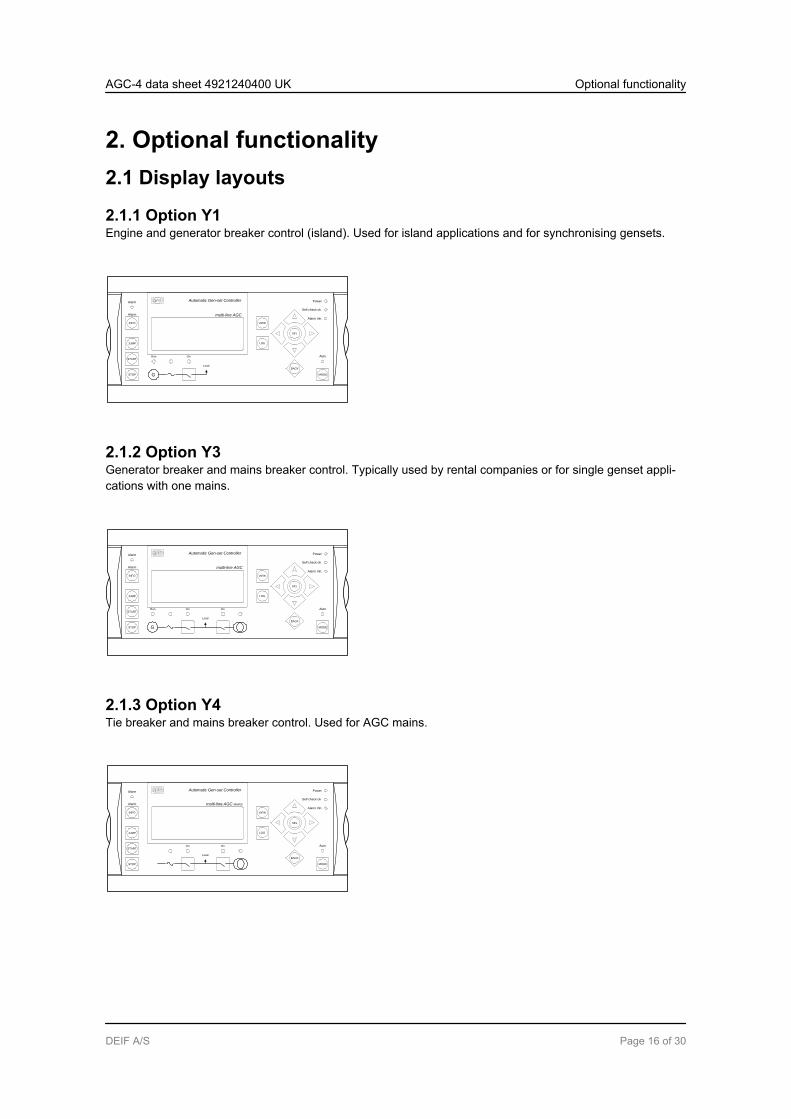
2.1.1 Option Y1Engine and generator breaker control (island). Used for island applications and for synchronising gensets.
Automatic Gen-set Controller
multi-line AGC
VIEW
LOG
Auto
Alarm Inh.
Self check ok
Power
SEL
BACK
MODE
JUMP
START
INFO
STOP
Alarm
Alarm
OnRun
G
Load
2.1.2 Option Y3Generator breaker and mains breaker control. Typically used by rental companies or for single genset appli-cations with one mains.
Automatic Gen-set Controller
VIEW
LOG
Auto
Alarm Inh.
Self check ok
Power
SEL
BACK
MODE
JUMP
START
INFO
STOP
Alarm
Alarm
multi-line AGC
On On
Load
Run
G
2.1.3 Option Y4Tie breaker and mains breaker control. Used for AGC mains.
Automatic Gen-set Controller
VIEW
LOG
Auto
Alarm Inh.
Self check ok
Power
SEL
BACK
MODE
JUMP
START
INFO
STOP
Alarm
Alarm
multi-line AGC MAINS
On On
Load
AGC-4 data sheet 4921240400 UK Optional functionality
DEIF A/S Page 16 of 30

2.1.4 Option Y5Bus tie breaker control. Used for AGC BTBs.
Automatic Gen-set Controller
multi-line AGC BUS TIE
VIEW
LOG
Auto
Alarm Inh.
Self check ok
Power
SEL
BACK
On
INFO
JUMP
Alarm
Alarm
MODE
2.1.5 Option X3Additional operator's panel - AOP-1. Used for plant and/or genset control and status/alarm indication.
AOP-1
2.1.6 Option X4Additional operator's panel - AOP-2. Used for plant and/or genset control and status/alarm indication (maxi-mum 5 per AGC).
AOP-2
AGC-4 data sheet 4921240400 UK Optional functionality
DEIF A/S Page 17 of 30
2.2 Available options
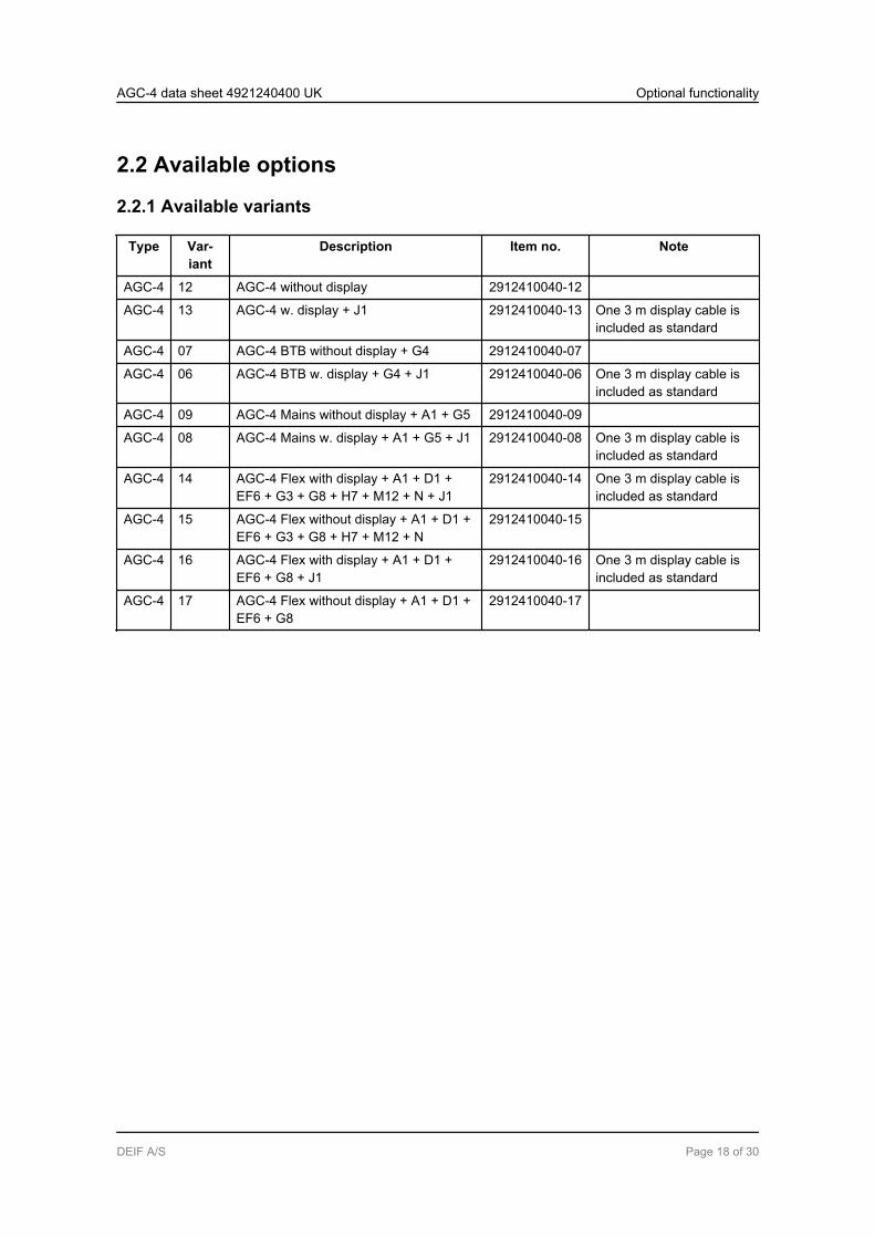
2.2.1 Available variants
Type Var-iant
Description Item no. Note
AGC-4 12 AGC-4 without display 2912410040-12
AGC-4 13 AGC-4 w. display + J1 2912410040-13 One 3 m display cable isincluded as standard
AGC-4 07 AGC-4 BTB without display + G4 2912410040-07
AGC-4 06 AGC-4 BTB w. display + G4 + J1 2912410040-06 One 3 m display cable isincluded as standard
AGC-4 09 AGC-4 Mains without display + A1 + G5 2912410040-09
AGC-4 08 AGC-4 Mains w. display + A1 + G5 + J1 2912410040-08 One 3 m display cable isincluded as standard
AGC-4 14 AGC-4 Flex with display + A1 + D1 +EF6 + G3 + G8 + H7 + M12 + N + J1
2912410040-14 One 3 m display cable isincluded as standard
AGC-4 15 AGC-4 Flex without display + A1 + D1 +EF6 + G3 + G8 + H7 + M12 + N
2912410040-15
AGC-4 16 AGC-4 Flex with display + A1 + D1 +EF6 + G8 + J1
2912410040-16 One 3 m display cable isincluded as standard
AGC-4 17 AGC-4 Flex without display + A1 + D1 +EF6 + G8
2912410040-17
AGC-4 data sheet 4921240400 UK Optional functionality
DEIF A/S Page 18 of 30

2.2.2 Available software options
Op-tion
Description Slotno.
Op-tiontype
Note
A Loss of mains protection package
A1 Time-dependent undervoltage (27t)Undervoltage and reactive power low (27Q)Vector jump (78)df/dt (ROCOF) (81)
SW
A4 Positive sequence (mains voltage low) (27) SW
A5 Directional overcurrent (67) SW
C2 Negative sequence voltage high (47)Negative sequence current high (46)Zero sequence voltage high (59)Zero sequence current high (50)Power-dependent reactive power (40)Inverse time overcurrent (51) (according to IEC 60255-151)
SW
D Voltage/VAr/cos phi control Not available forAGC mains andAGC bus tie
D1 Constant voltage control (stand-alone)Constant reactive power control (parallel with mains)Constant power factor control (parallel with mains)Reactive load sharing (island paralleling with other generators)
SW
G Load sharing/power management/plant management
G3 Load sharing with analogue lines 3 HW/SW
If M12 is present,G3 is a softwareoption
G4 Power management, 16 gensets, 8 bus tie breakers 7 SW Not with G5 orG8
G5 Power management, 16 gensets, 8 bus tie breakers, 16 mains 7 SW Not with G4 orG8
G8 Power management, 16 gensets (island mode) 7 SW Not with G4 orG5
H Serial communication
H7 CANbus (J1939): 7 SW Not with H5, H13or H6
AGC-4 data sheet 4921240400 UK Optional functionality
DEIF A/S Page 19 of 30
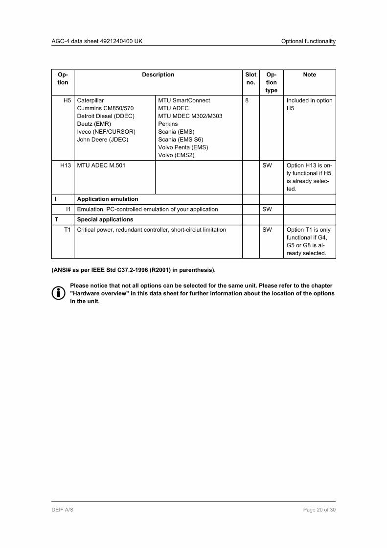
Op-tion
Description Slotno.
Op-tiontype
Note
H5 CaterpillarCummins CM850/570Detroit Diesel (DDEC)Deutz (EMR)Iveco (NEF/CURSOR)John Deere (JDEC)
MTU SmartConnectMTU ADECMTU MDEC M302/M303PerkinsScania (EMS)Scania (EMS S6)Volvo Penta (EMS)Volvo (EMS2)
8 Included in optionH5
H13 MTU ADEC M.501 SW Option H13 is on-ly functional if H5is already selec-ted.
I Application emulation
I1 Emulation, PC-controlled emulation of your application SW
T Special applications
T1 Critical power, redundant controller, short-circiut limitation SW Option T1 is onlyfunctional if G4,G5 or G8 is al-ready selected.
(ANSI# as per IEEE Std C37.2-1996 (R2001) in parenthesis).
Please notice that not all options can be selected for the same unit. Please refer to the chapter"Hardware overview" in this data sheet for further information about the location of the optionsin the unit.
AGC-4 data sheet 4921240400 UK Optional functionality
DEIF A/S Page 20 of 30

2.2.3 Available accessories
Acces-sory
Description Optiontype
Note
J Cables
J1 Display cable with plugs, 3 m. UL94 (V1) approved Other
J2 Display cable with plugs, 6 m. UL94 (V1) approved Other
J4 PC cable for option N-programming (Ethernet cable crossed), 3 m.UL94 (V1) approved
Other
J6 Display cable with plugs, 1 m. UL94 (V1) approved Other
J7 PC cable for utility software (USB), 3 m. UL94 (V1) approved Other
J8 Display CAN cable for DU-2 connection and 2 x plugs for cablesfor the Remote Maintenance Box
Other RMB connectorkit
K Documentation
K1 Designer's Reference Handbook (hard copy) Other
K2 CD-ROM with complete documentation Other
L Display gasket for IP54 Other Standard isIP52
Q Measurement accuracy Hardware
Q1 Verified class 0.5 Other
X Additional displays
X2 Additional standard display (DU-2). CANbus comm. Other Two options X2can be orderedfor each AGCunit
X3 Additional operator's panel (AOP-1): 16 configurable LEDs and 8configurable push-buttons
Other
X4 Additional operator's panel (AOP-2): 16 configurable LEDs, 8 con-figurable buttons and 1 status relay. CANbus comm.
Other Five options X4can be orderedfor each AGCunit
Y Display layout Hardware
Y1 Engine and generator breaker control (island) Other Available forAGC gensetcontroller
Y3 Generator breaker and mains breaker control Other Available forAGC gensetcontroller
Y4 Tie breaker and mains breaker control Other Available forAGC mainscontroller
AGC-4 data sheet 4921240400 UK Optional functionality
DEIF A/S Page 21 of 30

Acces-sory
Description Optiontype
Note
Y5 Bus tie breaker control Other Available forAGC BTB con-troller
2.2.4 Hardware options and slot number location
Ethernet
787776757473 96 979594929190 9389888785 8683 8482818079
727169 70686765 6662 6359 60 615856 575553 54 645251504947464443 45 4841403837 39 42
Service port Display
Ethernet
CAN BCAN A
Power
Self check okAlarm inhibit
1
4
9
5 6
3
7 8
2
1 : The numbers in the drawing above refer to the slot numbers indicated in the table below.
AGC-4 data sheet 4921240400 UK Optional functionality
DEIF A/S Page 22 of 30
Slot # Option/stand-ard
Description
1 Terminal 1-28, power supply
Standard 8-36V DC supply, 11 W; 1 x status output relay; 5 x relay outputs; 2 x pulse out-puts (kWh, kVArh or configurable open collector outputs); 5 x digital inputs
2 Terminal 29-36, communication
H2 Modbus RTU (RS485)
H3 Profibus DP
H9 Modbus RS232 for modem
H8.2 External I/O modules
M13.2 7 x binary inputs
M14.2 4 x relay outputs
3 Terminal 37-64, in-/outputs/load sharing
M12 13 x digital inputs; 4 x relay outputs (SW option if G3 is present)
G3 Active power load sharing; reactive power load sharing (requires D1) (SW op-tion if M12 is present)
4 Terminal 65-72, governor, AVR, in-/outputs
Standard 4 x relay
E1 2 x +/-25 mA out
E2 2 x 0(4)...20 mA out
EF2 1 x +/-25 mA out; 1 x 0(4)...20 mA out
EF4 1 x +/-25 mA out; 2 x relay
EF5 1 x +/-25 mA out; 1 x PWM out; 2 x relay
EF6 2 x +/-25 mA out; 1 x PWM out
5 Terminal 73-89, AC measuring
Standard 3 x generator voltage; 3 x generator current; 3 x busbar/mains voltage
6 Terminal 90-97, in-/outputs
F1 2 x 0(4)...20 mA out, transducer
M13.6 7 x digital inputs
M14.6 4 x relay outputs
M15.6 4 x 4...20 mA inputs
7 Terminal 98-125, engine I/F
AGC-4 data sheet 4921240400 UK Optional functionality
DEIF A/S Page 23 of 30

Slot # Option/stand-ard
Description
Standard 8-36V DC supply, 5 W; 1 x magnetic pick-up (MPU); 3 x multi-inputs; 7 x digitalinputs; 4 x relay outputs
H7 J1939 engine comm. and MTU ADEC
8 Terminal 126-133, engine communication, in-/outputs
H5/H13 MTU (ADEC/MDEC) + J1939 (engine brands available in option H7)
H6 Cummins GCS
H8.8 External I/O modules
M13.8 7 x digital inputs
M14.8 4 x relay outputs
M15.8 4 x 4...20 mA inputs
9 LED I/F
N - Modbus TCP/IP- EtherNet/IP- SMS/e-mail alarms
There can only be one hardware option in each slot. It is e.g. not possible to select option H2and option H3 at the same time, because both options require a PCB in slot #2.
Besides the hardware options shown on this page, it is possible to select the software optionsmentioned in the chapter "Available options".
It is possible to have option H7 and option G5 at the same time, but as soon as an engine pro-tocol has been selected in menu 7561, the CAN-A output will be locked for engine communica-tion.
If option H7 is selected, it is not possible to have options H5, H13 and H6 even though slot #8 isfree.
It is only possible to select one of the options H8.2 and H8.8.
AGC-4 data sheet 4921240400 UK Optional functionality
DEIF A/S Page 24 of 30

3. Technical information3.1 Specifications and dimensions
3.1.1 Technical specifications
Accuracy Class 1.0-25...15...30...70°CTemperature coefficient: +/-0.2% of full scale per 10°CClass 0.5 with option Q1
Positive, negative and zero sequence alarms: class 1 within 5% voltage unbalanceClass 1.0 for negative sequence currentFast overcurrent: 3% of 350%*InAnalogue outputs: class 1.0 according to total rangeOption EF4/EF5: class 4.0 according to total rangeTo IEC/EN60688
Operatingtemperature
-25…70°C (-13...158°F)-25...60°C (-13...140°F) if Modbus TCP/IP (option N) is available in the controller.(UL/cUL Listed: max. surrounding air temperature: 55°C/131°F)
Storage tem-perature
-40…70°C (-40...158°F)
Climate 97% RH to IEC 60068-2-30
Operating al-titude
0-4000 m above sea levelDerating 2001-4000 m above sea level:Max. 480V AC phase-phase 3W4 measuring voltageMax. 690V AC phase-phase 3W3 measuring voltage
Measuringvoltage
100-690V AC +/-20%(UL/cUL Listed: 600V AC phase-phase)Consumption: max. 0.25 VA/phase
Measuringcurrent
-/1 or -/5 A AC(UL/cUL Listed: from CTs 1-5 A)Consumption: max. 0.3 VA/phase
Current over-load
4 x In continuously20 x In, 10 sec. (max. 75 A)80 x In, 1 sec. (max. 300 A)
Measuringfrequency
30...70 Hz
Aux. supply Terminals 1 and 2: 12/24V DC (8...36 V continuously, 6 V 1 sec.). Max. 11 W consump-tionTerminals 98 and 99: 12/24V DC (8...36 V continuously, 6 V 1 sec.). Max. 5 W consump-tionThe aux. supply inputs are to be protected by a 2 A slow blow fuse. (UL/cUL Listed: AWG24)
AGC-4 data sheet 4921240400 UK Technical information
DEIF A/S Page 25 of 30

Binary inputs Optocoupler, bi-directionalON: 8...36V DCImpedance: 4.7 kΩOFF: <2V DC
Analogue in-puts
-10...+10V DC: not galvanically separated. Impedance: 100 kΩ0(4)...20 mA: impedance 50 Ω. Not galvanically separatedRPM (MPU): 2...70V AC, 10...10000 Hz, max. 50 kΩ
Multi-inputs 0(4)...20 mA: 0-20 mA, +/-1%. Not galvanically separatedBinary: max. resistance for ON detection: 100 Ω. Not galvanically separatedPt100/1000: -40...250°C, +/-1%. Not galvanically separated. To IEC/EN60751VDO: 0-1700 Ω, +/-2%. Not galvanically separatedV DC: 0...40V DC, +/-1%. Not galvanically separated
Relay outputs Electrical rating: 250V AC/30V DC, 5 A. (UL/cUL Listed: 250V AC/24V DC, 2 A resistiveload)Thermal rating @ 50°C: 2 A: continuously. 4 A: ton= 5 sec., toff = 15 sec.(Unit status output: 1 A)
Open collec-tor outputs
Supply: 8...36V DC, max. 10 mA (terminal 20, 21, 22 (com))
Analogue out-puts
0(4)...20 mA and +/-25 mA. Galvanically separated. Active output (internal supply). Loadmax. 500 Ω. (UL/cUL Listed: max. 20 mA output)Update rate: transducer output: 250 ms. Regulator output: 100 ms
Load sharinglines
-5...0...+5V DC. Impedance: 23.5 kΩ
Galvanic sep-aration
Between AC voltage and other I/Os: 3250 V, 50 Hz, 1 min.Between AC current and other I/Os: 2200 V, 50 Hz, 1 min.Between analogue outputs and other I/Os: 550 V, 50 Hz, 1 min.Between binary input groups and other I/Os: 550 V, 50 Hz, 1 min.
AGC-4 data sheet 4921240400 UK Technical information
DEIF A/S Page 26 of 30
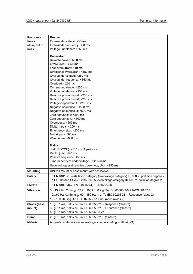
Responsetimes(delay set tomin.)
Busbar:Over-/undervoltage: <50 msOver-/underfrequency: <50 msVoltage unbalance: <250 ms
Generator:Reverse power: <250 msOvercurrent: <250 msFast overcurrent: <40 msDirectional overcurrent: <150 msOver-/undervoltage: <250 msOver-/underfrequency: <350 msOverload: <250 msCurrent unbalance: <250 msVoltage unbalance: <250 msReactive power import: <250 msReactive power export: <250 msVoltage-dependent I>: <250 msNegative sequence I: <500 msNegative sequence U: <500 msZero sequence I: <500 msZero sequence U: <500 msOverspeed: <500 msDigital inputs: <250 msEmergency stop: <200 msMulti-inputs: 800 msWire failure: <600 ms
Mains:df/dt (ROCOF): <130 ms (4 periods)Vector jump: <40 msPositive sequence: <60 msTime-dependent undervoltage, Ut<: <50 msUndervoltage and reactive power low, UQ<: <250 ms
Mounting DIN-rail mount or base mount with six screws
Safety To EN 61010-1, installation category (overvoltage category) III, 600 V, pollution degree 2To UL 508 and CSA 22.2 no. 14-05, overvoltage category III, 600 V, pollution degree 2
EMC/CE To EN 61000-6-2, EN 61000-6-4, IEC 60255-26.
Vibration 3…13.2 Hz: 2 mmpp. 13.2…100 Hz: 0.7 g. To IEC 60068-2-6 & IACS UR E1010…60 Hz: 0.15mmpp. 60…150 Hz: 1 g. To IEC 60255-21-1 Response (class 2)10…150 Hz: 2 g. To IEC 60255-21-1 Endurance (class 2)
Shock (basemount)
10 g, 11 ms, half sine. To IEC 60255-21-2 Response (class 2)30 g, 11 ms, half sine. To IEC 60255-21-2 Endurance (class 2)50 g, 11 ms, half sine. To IEC 60068-2-27
Bump 20 g, 16 ms, half sine. To IEC 60255-21-2 (class 2)
Material All plastic materials are self-extinguishing according to UL94 (V1)
AGC-4 data sheet 4921240400 UK Technical information
DEIF A/S Page 27 of 30

Plug connec-tions
AC current: 0.2-4.0 mm2 stranded wire. (UL/cUL Listed: AWG 18)AC voltage: 0.2-2.5 mm2 stranded wire. (UL/cUL Listed: AWG 20)Relays: (UL/cUL Listed: AWG 22)Terminals 98-116: 0.2-1.5 mm2 stranded wire. (UL/cUL Listed: AWG 24)Other: 0.2-2.5mm2 stranded wire. (UL/cUL Listed: AWG 24)Display: 9-pole Sub-D femaleService port: USB A-B
Protection Unit: IP20. Display: IP52 (IP54 with gasket: option L). (UL/cUL Listed: Type Complete De-vice, Open Type). To IEC/EN 60529
Governorsand AVRs
Multi-line 2 interfaces to all governors and AVRs using analogue, relay control or CAN-based J1939 communicationSee interfacing guide at www.deif.com
Approvals UL/cUL Listed to UL508Applies to VDE-AR-N 4105
UL markings Wiring: use 60/75°C copper conductors onlyMounting: for use on a flat surface of type 1 enclosureInstallation: to be installed in accordance with the NEC (US) or the CEC (Canada)
AOP-2:Maximum ambient temperature: 60°CWiring: use 60/75°C copper conductors onlyMounting: for use on a flat surface of type 3 (IP54) enclosure. Main disconnect must beprovided by installerInstallation: to be installed in accordance with the NEC (US) or the CEC (Canada)
DC/DC converter for AOP-2:Tightening torque: 0.5 Nm (4.4 lb-in)Wire size: AWG 22-14
Weight Base unit: 1.6 kg (3.5 lbs.)Option J1/J4/J6/J7: 0.2 kg (0.4 lbs.)Option J2: 0.4 kg (0.9 lbs.)Option J8: 0.3 kg (0.58 lbs.)Display: 0.4 kg (0.9 lbs.)
AGC-4 data sheet 4921240400 UK Technical information
DEIF A/S Page 28 of 30

3.1.2 Unit dimensions in mm (inches)
Display or AOP
20.0 (0.787)
230 (9.055)
215(8.465)
115 (4.528)
15 (0.59)
16
5 (
6.4
86
)
115 (4.528)
14
4 (
5.6
69
)
220 (8.661)
11
5 (
4.5
28)
AGC-4 data sheet 4921240400 UK Technical information
DEIF A/S Page 29 of 30
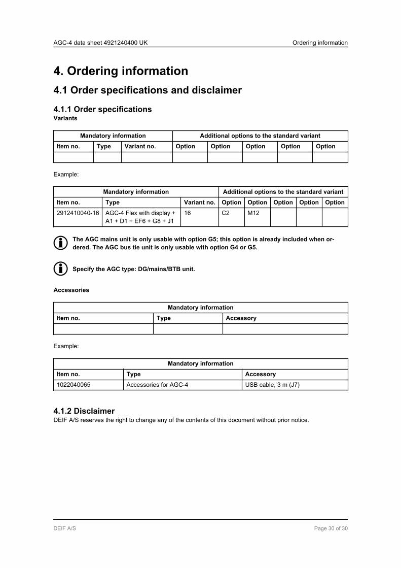
4. Ordering information4.1 Order specifications and disclaimer
4.1.1 Order specificationsVariants
Mandatory information Additional options to the standard variant
Item no. Type Variant no. Option Option Option Option Option
Example:
Mandatory information Additional options to the standard variant
Item no. Type Variant no. Option Option Option Option Option
2912410040-16 AGC-4 Flex with display +A1 + D1 + EF6 + G8 + J1
16 C2 M12
The AGC mains unit is only usable with option G5; this option is already included when or-dered. The AGC bus tie unit is only usable with option G4 or G5.
Specify the AGC type: DG/mains/BTB unit.
Accessories
Mandatory information
Item no. Type Accessory
Example:
Mandatory information
Item no. Type Accessory
1022040065 Accessories for AGC-4 USB cable, 3 m (J7)
4.1.2 DisclaimerDEIF A/S reserves the right to change any of the contents of this document without prior notice.
AGC-4 data sheet 4921240400 UK Ordering information
DEIF A/S Page 30 of 30