DATA SHEET AAT3685: Li-Ion/Polymer Battery Charger · AAT3685: Li-Ion/Polymer Battery Charger...
21
Skyworks Solutions, Inc. • Phone [781] 376-3000 • Fax [781] 376-3100 • [email protected] • www.skyworksinc.com 201888C • Skyworks Proprietary and Confidential Information • Products and Product Information are Subject to Change Without Notice • September 23, 2014 1 DATA SHEET AAT3685: Li-Ion/Polymer Battery Charger Applications Cellular telephones Digital still cameras Hand-held PCs MP3 players Personal Data Assistants (PDAs) Other lithium-ion/polymer battery-powered devices Features Adapter or USB charger Programmable up to 1 A max. 4.0 V to 5.5 V input voltage range High level of integration with internal: Charging device Reverse blocking diode Current sensing Automatic recharge sequencing Charge reduction loop Battery temperature monitoring Full battery charge auto turn-off Over-voltage protection Emergency thermal protection Power on reset and soft start Serial interface status reporting Pb-free, thermally-enhance TDFN (12-pin, 3 mm 3 mm) package (MSL1, 260 ºC per JEDEC J-STD-020) Description The AAT3685 BatteryManager™ is a highly integrated single cell lithium-ion/polymer battery charger IC designed to operate with USB port or line adapter inputs. It requires the minimum number of external components. The AAT3685 precisely regulates battery charge voltage and current for 4.2 V lithium-ion/polymer battery cells. Regardless of the type of input power source (USB or adapter), the AAT3685 can be programmed for two separate constant current charge levels up to 1 A. An optional Charge Reduction Loop is built in to allow users to charge the battery with available current from the charge supply, while keeping the port voltage regulated. Battery temperature and charge state are fully monitored for fault conditions. In the event of an over-voltage or over-temperature failure, the device will automatically shut down, thus protecting the charging device, control system, and the battery under charge. Status monitor output pins are provided to indicate the battery charge status by directly driving two external LEDs. A serial interface output is available to report any one of 14 various status states to a microcontroller. The AAT3685 is available in a Pb-free, thermally-enhanced, space-saving 12-pin 3 × 3mm TDFN package and is rated over the −40 °C to +85 °C temperature range. A typical application circuit is shown in Figure 1. The pin configurations are shown in Figure 2. Signal pin assignments and functional pin descriptions are provided in Table 1. Skyworks Green™ products are compliant with all applicable legislation and are halogen-free. For additional information, refer to Skyworks Definition of Green™, document number SQ04-0074.
Transcript of DATA SHEET AAT3685: Li-Ion/Polymer Battery Charger · AAT3685: Li-Ion/Polymer Battery Charger...
Skyworks Solutions, Inc. • Phone [781] 376-3000 • Fax [781] 376-3100 • [email protected] • www.skyworksinc.com 201888C • Skyworks Proprietary and Confidential Information • Products and Product Information are Subject to Change Without Notice • September 23, 2014 1
DATA SHEET
AAT3685: Li-Ion/Polymer Battery Charger Applications Cellular telephones
Digital still cameras
Hand-held PCs
MP3 players
Personal Data Assistants (PDAs)
Other lithium-ion/polymer battery-powered devices
Features Adapter or USB charger
Programmable up to 1 A max.
4.0 V to 5.5 V input voltage range
High level of integration with internal:
Charging device Reverse blocking diode Current sensing
Automatic recharge sequencing
Charge reduction loop
Battery temperature monitoring
Full battery charge auto turn-off
Over-voltage protection
Emergency thermal protection
Power on reset and soft start
Serial interface status reporting
Pb-free, thermally-enhance TDFN (12-pin, 3 mm 3 mm) package (MSL1, 260 ºC per JEDEC J-STD-020)
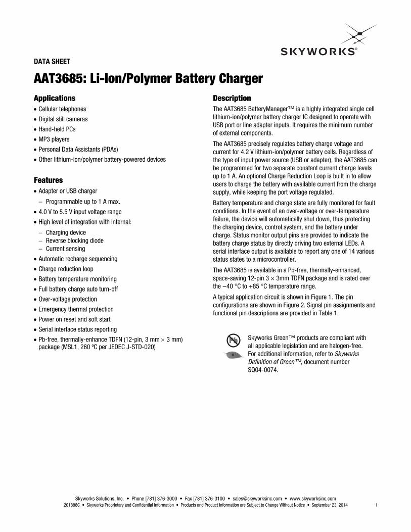
Description The AAT3685 BatteryManager™ is a highly integrated single cell lithium-ion/polymer battery charger IC designed to operate with USB port or line adapter inputs. It requires the minimum number of external components.
The AAT3685 precisely regulates battery charge voltage and current for 4.2 V lithium-ion/polymer battery cells. Regardless of the type of input power source (USB or adapter), the AAT3685 can be programmed for two separate constant current charge levels up to 1 A. An optional Charge Reduction Loop is built in to allow users to charge the battery with available current from the charge supply, while keeping the port voltage regulated.
Battery temperature and charge state are fully monitored for fault conditions. In the event of an over-voltage or over-temperature failure, the device will automatically shut down, thus protecting the charging device, control system, and the battery under charge. Status monitor output pins are provided to indicate the battery charge status by directly driving two external LEDs. A serial interface output is available to report any one of 14 various status states to a microcontroller.
The AAT3685 is available in a Pb-free, thermally-enhanced, space-saving 12-pin 3 × 3mm TDFN package and is rated over the −40 °C to +85 °C temperature range.
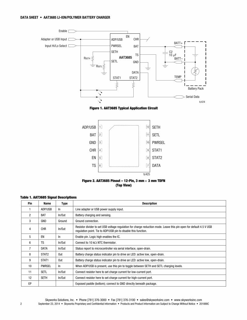
A typical application circuit is shown in Figure 1. The pin configurations are shown in Figure 2. Signal pin assignments and functional pin descriptions are provided in Table 1.
Skyworks Green™ products are compliant with all applicable legislation and are halogen-free.For additional information, refer to Skyworks Definition of Green™, document number SQ04-0074.
DATA SHEET • AAT3685 LI-ION/POLYMER BATTERY CHARGER
Skyworks Solutions, Inc. • Phone [781] 376-3000 • Fax [781] 376-3100 • [email protected] • www.skyworksinc.com 2 September 23, 2014 • Skyworks Proprietary and Confidential Information • Products and Product Information are Subject to Change Without Notice • 201888C
AAT3685
C210 μF
BATT−
TEMP
Adapter or USB Input
Battery Pack
Serial Data
ADP/USB
PWRSEL
GND
TS
BATBATT+
Input Hi/Lo Select
STAT1
RSETH
RSETL
SETH
SETL
CHREN
STAT2
DATA
Enable
tc424
Figure 1. AAT3685 Typical Application Circuit
ADP/USB
BAT
GND
1
CHR
EN
TS
SETH
SETL
PWRSEL
STAT1
STAT2
DATA
2
3
4
5
6
12
11
10
9
8
7
tc425
Figure 2. AAT3685 Pinout – 12-Pin, 3 mm 3 mm TDFN (Top View)
Table 1. AAT3685 Signal Descriptions
Pin Name Type Description
1 ADP/USB In Line adapter or USB power supply input.
2 BAT In/Out Battery charging and sensing.
3 GND Ground Ground connection.
4 CHR In/Out Resistor divider to set USB voltage regulation for charge reduction mode. Leave this pin open for default 4.5 V USB regulation point. Tie to ADP/USB pin to disable this function.
5 EN In Enable pin. Logic high enables the IC.
6 TS In/Out Connect to 10 k NTC thermistor.
7 DATA In/Out Status report to microcontroller via serial interface, open-drain.
8 STAT2 Out Battery charge status indicator pin to drive an LED: active low, open-drain.
9 STAT1 Out Battery charge status indicator pin to drive an LED: active low, open-drain.
10 PWRSEL In When ADP/USB is present, use this pin to toggle between SETH and SETL charging levels.
11 SETL In/Out Connect resistor here to set charge current for low-current port.
12 SETH In/Out Connect resistor here to set charge current for high-current port.
EP Exposed paddle (bottom); connect to GND directly beneath package.

DATA SHEET • AAT3685 LI-ION/POLYMER BATTERY CHARGER
Skyworks Solutions, Inc. • Phone [781] 376-3000 • Fax [781] 376-3100 • [email protected] • www.skyworksinc.com 201888C • Skyworks Proprietary and Confidential Information • Products and Product Information are Subject to Change Without Notice • September 23, 2014 3
Electrical and Mechanical Specifications Table 2 shows the AAT3685 feature options. The absolute maximum ratings of the AAT3685 are provided in Table 3, the thermal information is listed in Table 4, and electrical specifications are provided in Table 5.
Typical performance characteristics of the AAT3685 are illustrated in Figures 3 through 21.
Table 2. AAT3685 Feature Options
Part Number Internal Pull-up Resistor on EN Pin Can Leave TS Pin Open
AAT3685 No No
AAT3685-1 Yes Yes
Table 3. AAT3685 Absolute Maximum Ratings (Note 1)
Parameter Symbol Minimum Typical Maximum Units
ADP/USB input voltage, <30 ms, duty cycle <10% VADP 0.3 7.0 V
ADP/USB input voltage, continuous VADP 0.3 6.0 V
BAT, PWRSEL, SETH, SETL, STAT1, STAT2, DATA, TS, CHR, EN VN 0.3 6.0 V
Operating junction temperature range TJ 40 +85 ºC
Maximum soldering temperature (at leads) TLEAD 300 ºC
Note 1: Exposure to maximum rating conditions for extended periods may reduce device reliability. There is no damage to device with only one parameter set at the limit and all other parameters set at or below their nominal value. Exceeding any of the limits listed may result in permanent damage to the device.
Table 4. AAT3685 Thermal Information
Parameter Symbol Value Units
Maximum thermal resistance (Note 1) JA 50 ºC/W
Maximum power dissipation PD 2 W
Note 1: Mounted on an FR4 board.
CAUTION: Although this device is designed to be as robust as possible, electrostatic discharge (ESD) can damage this device. This device must be protected at all times from ESD. Static charges may easily produce potentials of several kilovolts on the human body or equipment, which can discharge without detection. Industry-standard ESD precautions should be used at all times.

DATA SHEET • AAT3685 LI-ION/POLYMER BATTERY CHARGER
Skyworks Solutions, Inc. • Phone [781] 376-3000 • Fax [781] 376-3100 • [email protected] • www.skyworksinc.com 4 September 23, 2014 • Skyworks Proprietary and Confidential Information • Products and Product Information are Subject to Change Without Notice • 201888C
Table 5. AAT3685 Electrical Specifications (1 of 2) (Note 1) (VADP = 5 V, TA = –40 C to +85 C. Unless Otherwise Noted, Typical Values are TA = 25 C)
Parameter Symbol Test Condition Min Typical Max Units
Operation
Input voltage range ADP/USB 4.0 5.5 V
Under-voltage lockout VUVLO
Rising edge 3.0 V
Under-voltage lockout hysteresis 150 mV
Operating current IOP CC charge current = 500 mA 0.75 1.5 mA
Sleep mode current ISLEEP VBAT = 4.25 V 0.3 1.0 A
Reverse leakage current from BAT pin ILEAKAGE VBAT = 4 V, ADP/USB pin open 1.0 A
End of charge voltage accuracy (Note 2) VBAT_EOC 4.158 4.2 4.242 V
EOC voltage tolerance VBAT/VBAT 0.5 %
Preconditioning voltage threshold VMIN 2.8 3.0 3.15 V
Battery recharge voltage threshold VRCH VBAT_EOC − 0.1 V
Charge reduction regulation VADP/USB_CHR No connection on CHR pin 4.3 4.5 4.64 V
CHR pin voltage accuracy VCHR 1.9 2.0 2.1 V
Current Regulation
Charge current ICH 50 1000 mA
Charge current regulation tolerance ICH/ICH 10 %
SETH pin voltage VSETH CC Mode 2.0 V
SETL pin voltage VSETL CC Mode 2.0 V
Current set factor: ICHARGE/ISETH KIUH 2000
Current set factor: ICHARGE/ISETL KIUL 2000
Charging Devices
Charge MOSFET transistor on resistance RDS(ON)U VIN = 5.5 V 0.4 0.5 0.65

DATA SHEET • AAT3685 LI-ION/POLYMER BATTERY CHARGER
Skyworks Solutions, Inc. • Phone [781] 376-3000 • Fax [781] 376-3100 • [email protected] • www.skyworksinc.com 201888C • Skyworks Proprietary and Confidential Information • Products and Product Information are Subject to Change Without Notice • September 23, 2014 5
Table 5. AAT3685 Electrical Specifications (2 of 2) (Note 1) (VADP = 5 V, TA = –40 C to +85C. Unless Otherwise Noted, Typical Values are TA = 25 C)
Logic Control/Protection
Input high threshold VPWRSEL(H) 1.6 V
Input low threshold VPWRSEL(L) 0.4 V
Input high threshold VEN(H) 1.6 V
Input low threshold VEN(L) 0.4 V
Output low voltage VSTAT STAT pin sinks 4 mA 0.4 V
STAT pin current sink capability ISTAT 8.0 mA
Over-voltage protection threshold VOVP 4.4 V
Pre-charge current ITK/ICHG For SETH Mode 10 %
For SETL Mode 50 %
Charge termination threshold current ITERM/ICHG For SETH Mode 7.5 %
Charge termination threshold current ITERM/ICHG For SETL Mode 35 %
Current source from TS pin ITS 70 80 90 A
TS hot temperature fault TS1 Threshold 310 330 350 mV
Hysteresis 15 mV
TS cold temperature fault TS2 Threshold 2.2 2.3 2.4 V
Hysteresis 10 mV
DATA pin sink current IDATA DATA pin is active low state 3.0 mA
Input high threshold VDATA(H) 1.6 V
Input low threshold VDATA(L) 0.4 V
Status request pulse width SQPULSE Status request 200 ns
System clock period tPERIOD 50 s
Data output frequency fDATA 20 kHz
Over-temperature shutdown threshold TOVSD 145 °C
Note 1: Performance is guaranteed only under the conditions listed in this table.
Note 2: The AAT3685 output charge voltage is specified over the 0 to 70 °C ambient temperature range; operation over the −40 °C to +85 °C temperature range is guaranteed by design.

DATA SHEET • AAT3685 LI-ION/POLYMER BATTERY CHARGER
Skyworks Solutions, Inc. • Phone [781] 376-3000 • Fax [781] 376-3100 • [email protected] • www.skyworksinc.com 6 September 23, 2014 • Skyworks Proprietary and Confidential Information • Products and Product Information are Subject to Change Without Notice • 201888C
Typical Performance Characteristics (VADP = 5 V, TA = –40 C to +85C. Unless Otherwise Noted, Typical Values are TA = 25 C)
RSET (kΩΩ)
IFAST
CHAR
GE (m
A)
10
100
1000
10000
1 10 100 1000
SETL
SETH
tc43
6
Figure 3. IFASTCHARGE vs RSET
Temperature (°°C)
4.040
4.050
4.060
4.070
4.080
4.090
4.100
4.110
4.120
4.130
4.140
-50 -25 0 25 50 75 100
VRCH
(V)
tc43
8
Figure 5. Recharge Voltage vs Temperature
Temperature (°°C)
VMIN
(V)
2.95
2.96
2.97
2.98
2.99
3.00
3.01
3.02
3.03
3.04
3.05
-50 -25 0 25 50 75 100
tc44
0
Figure 7. Preconditioning Threshold Voltage vs Temperature
Supply Voltage (V)
VBAT
(V)
4.158
4.179
4.200
4.221
4.242
4.5 4.75 5 5.25 5.5
tc43
7
Figure 4. Battery Voltage vs Supply Voltage
Temperature (°°C)
4.158
4.179
4.200
4.221
4.242
-50 -25 0 25 50 75 100
VEOC
(V)
tc43
9
Figure 6. End of Charge Voltage vs Temperature
Temperature (ºC)
ICH (m
A)
80
90
100
110
120
-50 -25 0 25 50 75 100
tc44
1
Figure 8. Preconditioning Charge Current vs Temperature (SETH; RSETH = 3.83 k)
DATA SHEET • AAT3685 LI-ION/POLYMER BATTERY CHARGER
Skyworks Solutions, Inc. • Phone [781] 376-3000 • Fax [781] 376-3100 • [email protected] • www.skyworksinc.com 201888C • Skyworks Proprietary and Confidential Information • Products and Product Information are Subject to Change Without Notice • September 23, 2014 7
Temperature (ºC)
900
920
940
960
980
1000
1020
1040
1060
1080
1100
-50 -25 0 25 50 75 100
ICH (m
A)
tc44
2
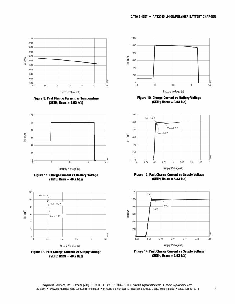
Figure 9. Fast Charge Current vs Temperature (SETH; RSETH = 3.83 k)
Battery Voltage (V)
0
20
40
60
80
100
120
2.5 3 3.5 4 4.5
ICH (m
A)
tc44
4
Figure 11. Charge Current vs Battery Voltage (SETL; RSETL = 40.2 k)
0
20
40
60
80
100
120
4 4.5 5.5 6.55 6
VBAT = 3.3 V
VBAT = 3.5 V
VBAT = 3.9 V
Supply Voltage (V)
ICH (m
A)
tc44
6
Figure 13. Fast Charge Current vs Supply Voltage (SETL; RSETL = 40.2 k)
Battery Voltage (V)
0
200
400
600
800
1000
1200
2.5 3 3.5 4 4.5
ICH (m
A)
tc44
3
Figure 10. Charge Current vs Battery Voltage (SETH; RSETH = 3.83 k)
Supply Voltage (V)
0
200
400
600
800
1000
1200
4 4.25 4.5 4.75 5 5.25 5.5 5.75 6
VBAT = 3.3 V
VBAT = 3.9 V
VBAT = 3.5 V
ICH (m
A)
tc44
5
Figure 12. Fast Charge Current vs Supply Voltage (SETH; RSETH = 3.83 k)
0
200
400
600
800
1000
1200
4.40 4.50 4.60 4.70 4.80 4.90 5.00
25 ºC
70 ºC
0 ºC
Supply Voltage (V)
ICH (m
A)
tc44
7
Figure 14. Fast Charge Current vs Supply Voltage (SETH; RSETH = 3.83 k)
DATA SHEET • AAT3685 LI-ION/POLYMER BATTERY CHARGER
Skyworks Solutions, Inc. • Phone [781] 376-3000 • Fax [781] 376-3100 • [email protected] • www.skyworksinc.com 8 September 23, 2014 • Skyworks Proprietary and Confidential Information • Products and Product Information are Subject to Change Without Notice • 201888C
Supply Voltage (V)
VIH
(V)
0.4
0.5
0.6
0.7
0.8
0.9
1.0
1.1
1.2
1.3
1.4
4.2 4.4 4.6 4.8 5 5.2 5.4 5.6 5.8 6
–40 ºC +25 ºC
+85 ºC
tc44
8
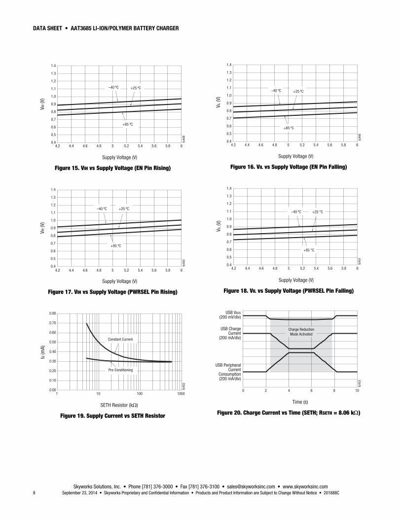
Figure 15. VIH vs Supply Voltage (EN Pin Rising)
0.4
0.5
0.6
0.7
0.8
0.9
1.0
1.1
1.2
1.3
1.4
4.2 4.4 4.6 4.8 5 5.2 5.4 5.6 5.8 6
Supply Voltage (V)
VIH
(V)
–40 ºC +25 ºC
+85 ºC
tc45
0
Figure 17. VIH vs Supply Voltage (PWRSEL Pin Rising)
SETH Resistor (kΩΩ)
IQ (m
A)
0.00
0.10
0.20
0.30
0.40
0.50
0.60
0.70
0.80
1 10 100 1000
Constant Current
Pre-Conditioning
tc45
2
Figure 19. Supply Current vs SETH Resistor
0.4
0.5
0.6
0.7
0.8
0.9
1.0
1.1
1.2
1.3
1.4
4.2 4.4 4.6 4.8 5 5.2 5.4 5.6 5.8 6
VIL (
V)
–40 ºC +25 ºC
+85 ºC
tc44
9
Supply Voltage (V)
Figure 16. VIL vs Supply Voltage (EN Pin Falling)
0.4
0.5
0.6
0.7
0.8
0.9
1.0
1.1
1.2
1.3
1.4
4.2 4.4 4.6 4.8 5 5.2 5.4 5.6 5.8 6
+25 °C
+85 °C
VIL (
V)–40 ºC
tc45
1
Supply Voltage (V)
Figure 18. VIL vs Supply Voltage (PWRSEL Pin Falling)
Time (s)
USB VBUS(200 mV/div)
USB ChargeCurrent
(200 mA/div)
USB PeripheralCurrent
Consumption(200 mA/div)
0 2 4 6 8 10
Charge ReductionMode Activated
tc45
3
Figure 20. Charge Current vs Time (SETH; RSETH = 8.06 k)

DATA SHEET • AAT3685 LI-ION/POLYMER BATTERY CHARGER
Skyworks Solutions, Inc. • Phone [781] 376-3000 • Fax [781] 376-3100 • [email protected] • www.skyworksinc.com 201888C • Skyworks Proprietary and Confidential Information • Products and Product Information are Subject to Change Without Notice • September 23, 2014 9
Temperature (ºC)
TS P
in C
Urre
nt (mm
A)
72
74
76
78
80
82
84
86
88
-50 -25 0 25 50 75 100
tc45
4
Figure 21. Temperature Sense Output Current vs Temperature

DATA SHEET • AAT3685 LI-ION/POLYMER BATTERY CHARGER
Skyworks Solutions, Inc. • Phone [781] 376-3000 • Fax [781] 376-3100 • [email protected] • www.skyworksinc.com 10 September 23, 2014 • Skyworks Proprietary and Confidential Information • Products and Product Information are Subject to Change Without Notice • 201888C
ChargeControl
CurrentCompare
Reverse Blocking
CV/Precharge
ADP/USBPWRSEL
ConstantCurrent
BAT
UVLO
Over-Temperature
Protect
ChargeStatusSTAT2
STAT1
TS
WindowComparator
80 A
SETHSETL
SerialDataDATA
GND
ChargeReduction
LoopCHR
EN
IC enable
tc425
Figure 22. AAT3685 Functional Block Diagram
Functional Description A functional block diagram is shown in Figure 22.
The AAT3685 is a highly integrated single cell li-ion/polymer battery charger IC designed to operate from adapter or USB port VBUS supplies, while requiring a minimum number of external components. The device precisely regulates battery charge voltage and current for 4.2 V li-ion/polymer battery cells.
The AAT3685 is specifically designed for being powered from a USB port VBUS supply, but it can also be powered from any input voltage source capable supplying 4.5 V to 5.5 V for loads up to 1 A. The AAT3685 constant charge current can be externally programmed for two levels, SETH and SETL, for maximum constant current charge levels up to 1 A. The SETH/L mode has an automatic Charge Reduction Loop control to allow users to charge the battery with limited available current from a port while maintaining the regulated port voltage. This system assures the battery charge function will not overload the port while charging if other system demands also share power with the respective port supply.
Status monitor output pins are provided to indicate the battery charge status by directly driving two external LEDs. A serial
interface output is available to report 14 various charge states to a system microcontroller.
Battery temperature and charge state are fully monitored for fault conditions. In the event of an over-voltage or over-temperature failure, the device will automatically shut down, thus protecting the charging device, control system, and the battery under charge. In addition to internal charge controller thermal protection, the AAT3685 also provides a temperature sense feedback function (TS pin) from the battery to shut down the device in the event the battery exceeds its own thermal limit during charging. All fault events are reported to the user either by the simple status LEDs or via the DATA pin function.
Charging Operation
The AAT3685 has four basic modes for the battery charge cycle and is powered from the input: pre-conditioning/trickle charge; constant current/fast charge; constant voltage; and end of charge. For reference, Figure 23 shows the current versus voltage profile during charging phases.

DATA SHEET • AAT3685 LI-ION/POLYMER BATTERY CHARGER
Skyworks Solutions, Inc. • Phone [781] 376-3000 • Fax [781] 376-3100 • [email protected] • www.skyworksinc.com 201888C • Skyworks Proprietary and Confidential Information • Products and Product Information are Subject to Change Without Notice • September 23, 2014 11
Battery Preconditioning
Before the start of charging, the AAT3685 checks several conditions in order to assure a safe charging environment. The input supply must be above the minimum operating voltage, or under-voltage lockout threshold (VUVLO), for the charging sequence to begin. In addition, the cell temperature, as reported by a thermistor connected to the TS pin from the battery, must be within the proper window for safe charging. When these conditions have been met and a battery is connected to the BAT pin, the AAT3685 checks the state of the battery. If the cell voltage is below the Preconditioning Voltage Threshold (VMIN), the AAT3685 begins preconditioning the cell.
The battery preconditioning trickle charge current is equal to the fast charge constant current divided by 10. For example, if the programmed fast charge current is 500 mA, then the preconditioning mode (trickle charge) current will be 50 mA. Cell preconditioning is a safety precaution for a deeply discharged battery and also aids in limiting power dissipation in the pass transistor when the voltage across the device is at the greatest potential.
Fast Charge/Constant Current Charging
Battery cell preconditioning continues until the voltage on the BAT pin exceeds the Preconditioning Voltage Threshold (VMIN). At this point, the AAT3685 begins the constant current fast charging phase. The fast charge constant current (ICC) amplitude is determined by the selected charge mode SETH or SETL and is programmed by the user via the RSETH and RSETL resistors. The AAT3685 remains in constant current charge mode until the battery reaches the voltage regulation point, VBAT.
Constant Voltage Charging
The system transitions to a constant voltage charging mode when the battery voltage reaches output charge regulation threshold (VBAT) during the constant current, fast charge phase. The regulation voltage level is factory programmed to 4.2 V (1%). The charge current in the constant voltage mode drops as the battery cell under charge reaches its maximum capacity.
End of Charge Cycle Termination and Recharge Sequence
When the charge current drops to 7.5% of the programmed fast charge current level in the constant voltage mode, the device terminates charging and goes into a sleep state. The charger will remain in a sleep state until the battery voltage decreases to a level below the battery recharge voltage threshold (VRCH).
When the input supply is disconnected, the charger will also automatically enter power-saving sleep mode. Only consuming an ultra-low 0.3 A in sleep mode, the AAT3685 minimizes battery drain when it is not charging. This feature is particularly useful in applications where the input supply level may fall below the battery charge or under-voltage lockout level. In such cases where the AAT3685 input voltage drops, the device will enter the sleep mode and automatically resume charging once the input supply has recovered from its fault condition.
System Operation Flow Chart
Figure 24 illustrates the system operation flow chart for the battery charger.
Constant CurrentCharge Phase
Constant VoltageCharge Phase
PreconditioningTrickle Charge
PhaseCharge Complete Voltage
Constant Current ModeVoltage Threshold
Regulated Current
Trickle Charge andTermination Threshold
I = CC/10
I = Max CC
tc427
Figure 23 . Current vs Voltage Profile during Charging Phases

DATA SHEET • AAT3685 LI-ION/POLYMER BATTERY CHARGER
Skyworks Solutions, Inc. • Phone [781] 376-3000 • Fax [781] 376-3100 • [email protected] • www.skyworksinc.com 12 September 23, 2014 • Skyworks Proprietary and Confidential Information • Products and Product Information are Subject to Change Without Notice • 201888C
No
No
No
No
No
Yes Yes
Yes
Yes
Yes
0
1
No
Yes
No
Yes
No
SwitchOn
UVLOVADP > VUVLO
Input PowerYes
Input DetectPWRSEL= ?
SETLCurrent Loop
SETHCurrent Loop
Power OnReset
SleepMode
FaultConditions Monitor
OV, OT
BatteryTemperature Monitor
VTS1 < VTS < VTS2
Shut DownMode
BatteryTemp. Fault Input Voltage
RegulationEnable
Recharge TestVRCH > VBAT
Preconditioning TestVMIN > VBAT
Low CurrentConditioning
Charge
CurrentCharging
Mode
ChargeCurrent
Reduction
Port Voltage TestVADP/USB < VADP/USB_CHR
VoltageCharging
ModeVoltage Phase Test
ChargeCompleted
IBAT > ITERM
tc428
Current Phase TestVEOC > VBAT
Figure 24. System Operation Flowchart for the Battery Charger
DATA SHEET • AAT3685 LI-ION/POLYMER BATTERY CHARGER
Skyworks Solutions, Inc. • Phone [781] 376-3000 • Fax [781] 376-3100 • [email protected] • www.skyworksinc.com 201888C • Skyworks Proprietary and Confidential Information • Products and Product Information are Subject to Change Without Notice • September 23, 2014 13
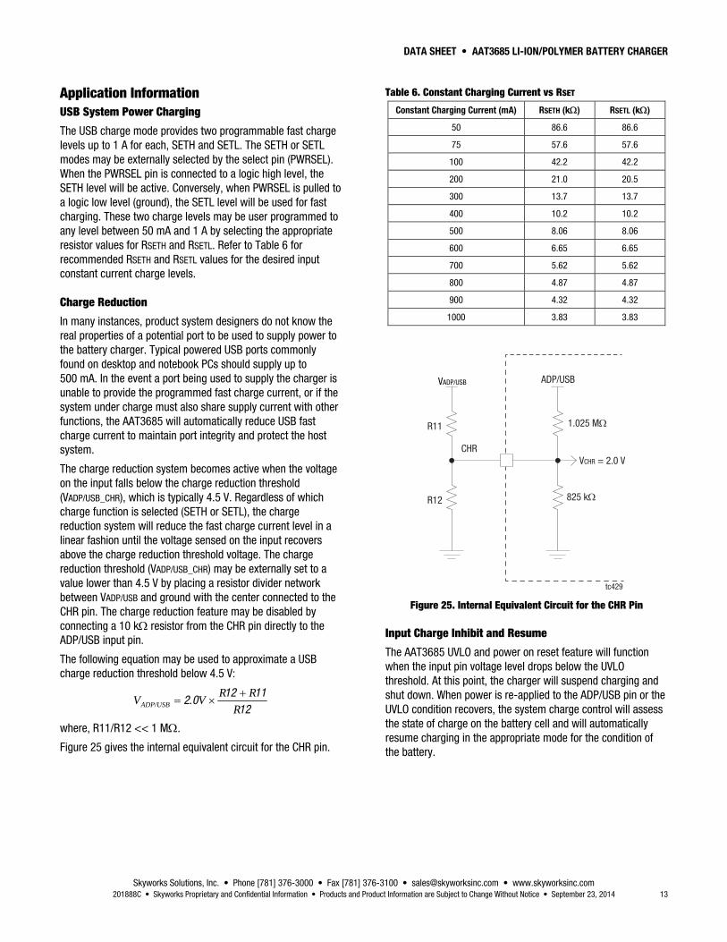
Application Information USB System Power Charging
The USB charge mode provides two programmable fast charge levels up to 1 A for each, SETH and SETL. The SETH or SETL modes may be externally selected by the select pin (PWRSEL). When the PWRSEL pin is connected to a logic high level, the SETH level will be active. Conversely, when PWRSEL is pulled to a logic low level (ground), the SETL level will be used for fast charging. These two charge levels may be user programmed to any level between 50 mA and 1 A by selecting the appropriate resistor values for RSETH and RSETL. Refer to Table 6 for recommended RSETH and RSETL values for the desired input constant current charge levels.
Charge Reduction
In many instances, product system designers do not know the real properties of a potential port to be used to supply power to the battery charger. Typical powered USB ports commonly found on desktop and notebook PCs should supply up to 500 mA. In the event a port being used to supply the charger is unable to provide the programmed fast charge current, or if the system under charge must also share supply current with other functions, the AAT3685 will automatically reduce USB fast charge current to maintain port integrity and protect the host system.
The charge reduction system becomes active when the voltage on the input falls below the charge reduction threshold (VADP/USB_CHR), which is typically 4.5 V. Regardless of which charge function is selected (SETH or SETL), the charge reduction system will reduce the fast charge current level in a linear fashion until the voltage sensed on the input recovers above the charge reduction threshold voltage. The charge reduction threshold (VADP/USB_CHR) may be externally set to a value lower than 4.5 V by placing a resistor divider network between VADP/USB and ground with the center connected to the CHR pin. The charge reduction feature may be disabled by connecting a 10 k resistor from the CHR pin directly to the ADP/USB input pin.
The following equation may be used to approximate a USB charge reduction threshold below 4.5 V:
121112
02R
RRV.VADP/USB
where, R11/R12 << 1 M.
Figure 25 gives the internal equivalent circuit for the CHR pin.
Table 6. Constant Charging Current vs RSET
Constant Charging Current (mA) RSETH (k) RSETL (k)
50 86.6 86.6
75 57.6 57.6
100 42.2 42.2
200 21.0 20.5
300 13.7 13.7
400 10.2 10.2
500 8.06 8.06
600 6.65 6.65
700 5.62 5.62
800 4.87 4.87
900 4.32 4.32
1000 3.83 3.83
1.025 M
825 k
R11
R12
VCHR = 2.0 V
ADP/USB
CHR
tc429
VADP/USB
Figure 25. Internal Equivalent Circuit for the CHR Pin
Input Charge Inhibit and Resume
The AAT3685 UVLO and power on reset feature will function when the input pin voltage level drops below the UVLO threshold. At this point, the charger will suspend charging and shut down. When power is re-applied to the ADP/USB pin or the UVLO condition recovers, the system charge control will assess the state of charge on the battery cell and will automatically resume charging in the appropriate mode for the condition of the battery.

DATA SHEET • AAT3685 LI-ION/POLYMER BATTERY CHARGER
Skyworks Solutions, Inc. • Phone [781] 376-3000 • Fax [781] 376-3100 • [email protected] • www.skyworksinc.com 14 September 23, 2014 • Skyworks Proprietary and Confidential Information • Products and Product Information are Subject to Change Without Notice • 201888C
Single Path Charging from a Line Adapter or USB Source
Most USB charging applications limit charging current to 500 mA due to the limitations of a USB port as a power source. The AAT3685 is capable of, and may be programmed for, constant current charge levels up to 1 A. Thus, charging operation is not just restricted to use with USB port supplies. Any power source may be used within the operating voltage limits as specified in the Electrical Characteristics section of this datasheet. This makes the AAT3685 perfect for applications that only have one input path, but may access either a line adapter source or a USB port supply.
In order to fully utilize the power capacity from a line adapter or USB port supply, program the SETH charge rate according to the highest charging current capacity of the two possible sources, providing that neither supply exceeds 1 A. A lower charge level may be set with the SETL charge rate and selection of the higher or lower charge rate is controlled via the PWRSEL function. If the programmed charge rate is greater than the current source capacity, there is little danger of system failure because the AAT3685 charge reduction loop will activate to automatically reduce the charging current and maintain a supply voltage set by the CHR threshold. If the input supply is incapable of maintaining an input voltage greater than the under-voltage lockout level of the AAT3685, the charge control will suspend charging until the source supply is capable of supplying the minimum input current to charge. At this point, the AAT3685 will automatically resume charging in the appropriate mode based on the battery cell voltage. In case of an over-temperature condition with a high charge current and large input-to-battery voltage difference, the device will cycle from charging to thermal shutdown and re-charge after temperature drops sufficiently, until the battery is charged to 4.2 V.
Enable/Disable
The AAT3685 provides an enable function to control the charger IC on and off. The enable (EN) pin is an active high. When pulled to a logic low level, the AAT3685 will be shut down and forced into the sleep state. Charging will be halted regardless of the battery voltage or charging state. When the device is re-enabled, the charge control circuit will automatically reset and resume charging functions with the appropriate charging mode based on the battery charge state and measured cell voltage.
Programming Charge Current
The fast charge constant current charge level for the ADP/USB input is programmed with set resistors placed between the SETH and SETL pins and ground. The accuracy of the fast charge, as well as the preconditioning trickle charge current, is dominated by the tolerance of the set resistors used. For this reason, 1% tolerance metal film resistors are recommended for programming the desired constant current level.
The fast charge constant current charge control provides for two current set levels, SETH and SETL. The PWRSEL pin is used to select the high or low charge current levels. When the PWRSEL pin is pulled to a voltage level above the VPWRSEL(H) threshold, the SETH current level will be selected. Conversely, this pin should be pulled below the VPWRSEL(L) to enable the SETL charge level. These two charge levels may be set to any level between 50 mA and 1 A, depending upon the system design requirements for a given charge application. Refer to Table 6 and Figure 26 for recommended RSETH and RSETL values.
RSET (kΩΩ)
IFAST
CHAR
GE (m
A)
10
100
1000
10000
1 10 100 1000
SETH
SETL
tc43
0
Figure 26. IFASTCHARGE vs RSET
Protection Circuitry
Over-Voltage Protection
An over-voltage event is defined as a condition where the voltage on the BAT pin exceeds the maximum battery charge voltage and is set by the over-voltage protection threshold (VOVP). If an over-voltage condition occurs, the AAT3685 charge control will shut down the device until voltage on the BAT pin drops below the over-voltage protection threshold (VOVP). The AAT3685 will resume normal charging operation after the over-voltage condition is removed. During an over-voltage event, the STAT LEDs will report a system fault; the actual fault condition may also be read via the DATA pin signal.
Over-Temperature Shutdown
The AAT3685 has a thermal protection control circuit which will shut down charging functions should the internal die temperature exceed the preset thermal limit threshold.
Battery Temperature Fault Monitoring
As shown in Figure 27, in the event of a battery over-temperature condition, the charge control will turn off the internal pass device and report a battery temperature fault on the DATA pin function. The STAT LEDs will also display a

DATA SHEET • AAT3685 LI-ION/POLYMER BATTERY CHARGER
Skyworks Solutions, Inc. • Phone [781] 376-3000 • Fax [781] 376-3100 • [email protected] • www.skyworksinc.com 201888C • Skyworks Proprietary and Confidential Information • Products and Product Information are Subject to Change Without Notice • September 23, 2014 15
system fault. After the system recovers from a temperature fault, the device will resume charging operation.
The AAT3685 checks battery temperature before starting the charge cycle, as well as during all stages of charging. This is accomplished by monitoring the voltage at the TS pin. This system is intended for use negative temperature coefficient (NTC) thermistors which are typically integrated into the battery package. Most commonly used NTC thermistors used in battery packs are approximately 10 k at room temperature (25 °C). The TS pin has been specifically designed to source 80 A of current to the thermistor. The voltage on the TS pin that results from the resistive load should stay within a window from 335 mV to 2.32 V. If the battery becomes too hot during charging due to an internal fault, the thermistor will heat up and reduce in value, thus pulling the TS pin voltage lower than the TS1 threshold, and the AAT3685 will halt charging and signal the fault condition. If the use of the TS pin function is not required by the system, it should be terminated to ground using a 10 k resistor. Alternatively, on the AAT3685-1, the TS pin may be left open.
TS–+
–
+
VREF2: 2.3 V
VREF1: 0.33 V
Battery Cold Fault
Battery Hot Fault
TS COLD (TS2)
TS HOT (TS1) RLO
RHI
VS
T
Battery Pack
AAT3685
tc455
Figure 27. Battery Temperature Sensing Operation
11
11
COLD
INCOLD
HOT
SHOT
HOTCOLDHOTCOLDS
LO
V
VR
V
VR
VVRRV
R
COLDLO
COLD
S
HI
RR
V
V
R11
1
Where,
VHOT = 0.33 V VCOLD= 2.3 V VS = supply voltage RHOT = NTC resistance at high temperature RCOLD = NTC resistance at low temperature
Battery Charge Status Indication
The AAT3685 indicates the status of the battery under charge with two different systems. First, the device has two status LED driver outputs. These two LEDs can indicate simple functions such as no battery charge activity, battery charging, charge complete, and charge fault. The AAT3685 also provides a bi-directional data reporting function so that a system microcontroller may interrogate the DATA pin and read any one of 14 system states.
Status Indicator Display
Simple system charging status may be displayed using one or two LEDs in conjunction with the STAT1 and STAT2 pins on the AAT3685. These two pins are simple switches to connect the display LED cathodes to ground. It is not necessary to use both display LEDs if a user simply wants to have a single lamp to show “charging” or “not charging.”
This can be accomplished by just using the STAT1 pin and a single LED. Using two LEDs and both STAT pins simply gives the user more information for charging states. Refer to Table 7 for LED display definitions.
Table 7. LED Display Status Conditions
Event Description STAT1 STAT2
Charge disabled or low supply Off Off
Charge enabled without battery Flash 1 Flash 1
Battery charging On Off
Charge completed Off On
Fault On On
The LED anodes should be connected to VADP/USB. The LEDs should be biased with as little current as necessary to create reasonable illumination; therefore, a ballast resistor should be placed between each of the LED cathodes and the STAT1/2 pins. LED current consumption will add to the over-thermal power budget for the device package, hence it is recommended to keep the LED drive current to a minimum. 2mA should be sufficient to drive most low-cost green, red, or multi-color LEDs. It is not recommended to exceed 8 mA for driving an individual status LED.
The required ballast resistor value can be estimated using the following formulas:
)/STAT(LED
)LED(FUSB/ADPB(STAT1/2) I
VVR
21
Example:
k.mA
V.V.RB(STAT1) 51
20205
Note: Red LED forward voltage (VF) is typically 2.0 V @ 2 mA.
Table 7 shows the status LED display conditions.

DATA SHEET • AAT3685 LI-ION/POLYMER BATTERY CHARGER
Skyworks Solutions, Inc. • Phone [781] 376-3000 • Fax [781] 376-3100 • [email protected] • www.skyworksinc.com 16 September 23, 2014 • Skyworks Proprietary and Confidential Information • Products and Product Information are Subject to Change Without Notice • 201888C
Digital Charge Status Reporting
The AAT3685 has a comprehensive digital data reporting system by use of the DATA pin feature. This function can provide detailed information regarding the state of the charging system. The DATA pin is a bi-directional port which will read back a series of data pulses when the system microcontroller asserts a request pulse. This single strobe request protocol will invoke one of 14 possible return pulse counts in which the microcontroller can look up based on the serial report shown in Table 8.
The DATA pin function is active low and should normally be pulled high to VADP/USB. This data line may also be pulled high to the same level as the high state for the logic I/O port on the system microcontroller. In order for the DATA pin control circuit to generate clean sharp edges for the data output and to maintain the integrity of the data timing for the system, the pull-up resistor on the data line should be low enough in value so that the DATA signal returns to the high state without delay. If the value of the pull-up resistor used is too high, the strobe pulse from the system microcontroller may exceed the maximum pulse time and the DATA output control could issue false status reports. A 1.5 k resistor is recommended when pulling the DATA pin high to 5.0 V at the VUSB input. If the data line is pulled high to a voltage level less than 5.0 V, the pull-up resistor may be calculated based on a recommended minimum pull-up current of 3 mA. Use the following formula:
mA
VR UP-PULL
UP-PULL 3
Data Timing
The system microcontroller should assert an active low data request pulse for minimum duration of 200ns; this is specified by tLO(DATA). Upon sensing the rising edge of the end of the data request pulse, the AAT3685 status data control will reply the data word back to the system microcontroller after a delay specified by the data report time specification tDATA(RPT). The period of the following group of data pulses will be specified by the tDATA specification.
Figures 28 and 29 depict the data pin application circuit and the timing diagram.
Table 8. Serial Data Report Table
N DATA Report Status
1 Chip over-temperature shutdown
2 Battery temperature fault
3 Over-voltage turn off
4 Not used
5 Not used
6 Not used
7 Not used
8 Not used
9 Not used
10 Not used
11 Not used
12 Not used
13 SETH battery condition mode
14 SETH charge reduction in constant current mode
15 SETH constant current mode
16 SETH constant voltage mode
17 SETH end of charging
18 SETL battery condition mode
19 SETL charge end of charging reduction in constant current mode
20 SETL constant current mode
21 SETL constant voltage mode
22 SETL end of charging
23 Data report error
AAT3685StatusControl
1.8 V to 5.0 V
DATA PinRPULL-UP
P GPIOPort
GPIO
IN
IN
OUT
OUT
tc431
Figure 28. Data Pin Application Circuit

DATA SHEET • AAT3685 LI-ION/POLYMER BATTERY CHARGER
Skyworks Solutions, Inc. • Phone [781] 376-3000 • Fax [781] 376-3100 • [email protected] • www.skyworksinc.com 201888C • Skyworks Proprietary and Confidential Information • Products and Product Information are Subject to Change Without Notice • September 23, 2014 17
SQ SQPULSE
Data
CK tSYNC
tDATA(RPT) = tSYNC + tLAT < 2.5PDATA
tOFF > 2PDATA
tLAT tOFF
N = 1 N = 2 N = 3
PDATA
System ResetSystem Start
tc432
Figure 29. Timing Diagram
Thermal Considerations
The AAT3685 is packaged in a Pb-free, 3 3 mm TDFN package which can provide up to 2.0 W of power dissipation when it is properly bonded to a printed circuit board and has a maximum thermal resistance of 50 °C/W. Many considerations should be taken into account when designing the printed circuit board layout, as well as the placement of the charger IC package in proximity to other heat generating devices in a given application design. The ambient temperature around the charger IC will also have an effect on the thermal limits of a battery charging application. The maximum limits that can be expected for a given ambient condition can be estimated by the following discussion.
First, the maximum power dissipation for a given situation should be calculated:
OPINCCBATIND IVIVVP (1)
Where:
PD = total power dissipation by the device VIN = input voltage level, VADP/USB VBAT = battery voltage as seen at the bat pin ICC = maximum constant fast charge current programmed for the application IOP = quiescent current consumed by the charger IC for normal operation.
Next, the maximum operating ambient temperature for a given application can be estimated based on the thermal resistance of the 3 3 mm TDFN package when sufficiently mounted to a PCB layout and the internal thermal loop temperature threshold.
DJAJA PTT (2)
Where:
TA = ambient temperature (°C) TJ = maximum device junction temperature protected by the thermal limit control (°C) PD = total power dissipation by the device (W) JA = package thermal resistance (°C/W)
Example: For an application where the fast charge current is set to 500 mA, VUSB = 5.0 V and the worst case battery voltage at 3.0 V, what is the maximum ambient temperature at which the thermal limiting will become active?
Given:
VUSB = 5.0 V VBAT = 3.0 V ICC = 500 mA IOP = 0.75 mA TJ = 140 °C JA = 50 °C/W
Using Equation 1, calculate the device power dissipation for the stated condition:
W.mA.V.mAV.V.PD 003751750055000305
The maximum ambient temperature before the AAT3685 thermal limit protection will shut down charging can now be calculated using Equation 2:
C.W.W/CCTA 918900375150140
Therefore, under the stated conditions for this worst case power dissipation example, the AAT3685 will suspend charging operations when the ambient operating temperature rises above 89.81 °C.
Capacitor Selection
Input Capacitor
In general, it is good design practice to place a decoupling capacitor between the ADP/USB pin and ground. An input capacitor in the range of 1 F to 22 F is recommended. If the source supply is unregulated, it may be necessary to increase the capacitance to keep the input voltage above the under-voltage lockout threshold during device enable and when battery charging is initiated.
If the AAT3685 input is to be used in a system with an external power supply source rather than a USB port VBUS, such as a

DATA SHEET • AAT3685 LI-ION/POLYMER BATTERY CHARGER
Skyworks Solutions, Inc. • Phone [781] 376-3000 • Fax [781] 376-3100 • [email protected] • www.skyworksinc.com 18 September 23, 2014 • Skyworks Proprietary and Confidential Information • Products and Product Information are Subject to Change Without Notice • 201888C
typical AC-to-DC wall adapter, then a CIN capacitor in the range of 10 F should be used. A larger input capacitor in this application will minimize switching or power bounce effects when the power supply is “hot plugged” in. Likewise, a 10 F or greater input capacitor is recommended for the USB input to help buffer the effects of USB source power switching noise and input cable impedance.
Output Capacitor
The AAT3685 only requires a 1 F ceramic capacitor on the BAT pin to maintain circuit stability. This value should be increased to 10 F or more if the battery connection is made any distance from the charger output. If the AAT3685 is to be used in applications where the battery can be removed from the charger, such as in the case of desktop charging cradles, an output capacitor greater than 10 F may be required to prevent the device from cycling on and off when no battery is present.
Printed Circuit Board Layout Considerations
For the best results, it is recommended to physically place the battery pack as close as possible to the AAT3685 BAT pin. To minimize voltage drops on the PCB, keep the high current carrying traces adequately wide. For maximum power
dissipation of the AAT3685 3 3 mm TDFN package, the metal substrate should be solder bonded to the board. It is also recommended to maximize the substrate contact to the PCB ground plane layer to further increase local heat dissipation. Refer to the AAT3685 evaluation board information for a good layout example.
Evaluation Board Description The AAT3685 Evaluation Board is used to test the performance of the AAT3685. An Evaluation Board schematic diagram is provided in Figure 30. Layer details for the Evaluation Board are shown in Figure 31. The Evaluation Board has additional components for easy evaluation; the actual bill of materials required for the system is shown in Table 9.
Package Information Package dimensions for the 10-pin TDFN package are shown in Figure 32. Tape & reel dimensions are shown in Figure 33.
GRNLED D2
REDLED D1
R8
1.5 kR5 R6
R9OpenR3
R4
R7
1 2 3
PWRSEL
J2
SW1
LOHI
DATA
1 2 3
ON/OFF
J1
ADP/USB1
BAT2
GND3
CHR4
EN5
TS6
DATA7
STAT28
STAT19
PWRSEL 10
SETL11
SETH12
AAT3685U1
12
TB1
BAT
GNDTS
ADP/USB
ADP/USB
GND
TDFN33-12
12345
Mini-B
10 FC2
10 FC1
GNDID
D+D-
123
TB2
OpenR2
OpenR1
1.5 k
10 k
8.06 k 40.2 k
1.5 k
tc433
Figure 30. AAT3685 Evaluation Board Schematic
DATA SHEET • AAT3685 LI-ION/POLYMER BATTERY CHARGER
Skyworks Solutions, Inc. • Phone [781] 376-3000 • Fax [781] 376-3100 • [email protected] • www.skyworksinc.com 201888C • Skyworks Proprietary and Confidential Information • Products and Product Information are Subject to Change Without Notice • September 23, 2014 19
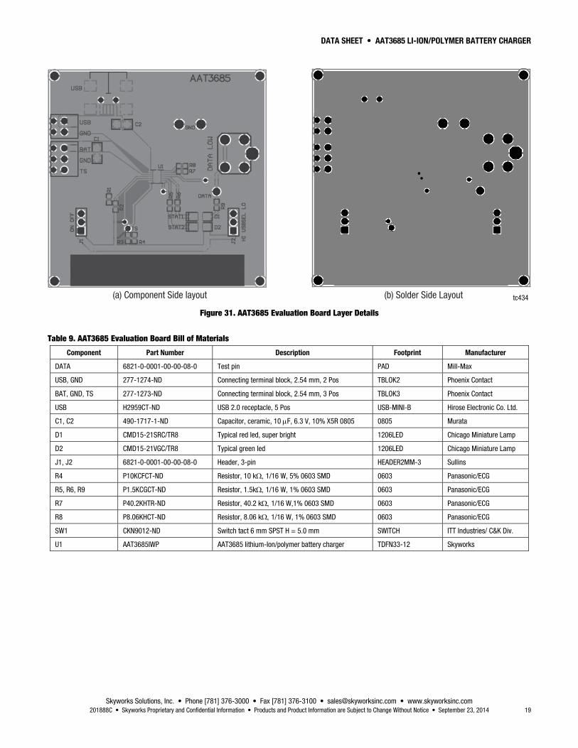
(a) Component Side layout (b) Solder Side Layout tc434
Figure 31. AAT3685 Evaluation Board Layer Details
Table 9. AAT3685 Evaluation Board Bill of Materials
Component Part Number Description Footprint Manufacturer
DATA 6821-0-0001-00-00-08-0 Test pin PAD Mill-Max
USB, GND 277-1274-ND Connecting terminal block, 2.54 mm, 2 Pos TBLOK2 Phoenix Contact
BAT, GND, TS 277-1273-ND Connecting terminal block, 2.54 mm, 3 Pos TBLOK3 Phoenix Contact
USB H2959CT-ND USB 2.0 receptacle, 5 Pos USB-MINI-B Hirose Electronic Co. Ltd.
C1, C2 490-1717-1-ND Capacitor, ceramic, 10 F, 6.3 V, 10% X5R 0805 0805 Murata
D1 CMD15-21SRC/TR8 Typical red led, super bright 1206LED Chicago Miniature Lamp
D2 CMD15-21VGC/TR8 Typical green led 1206LED Chicago Miniature Lamp
J1, J2 6821-0-0001-00-00-08-0 Header, 3-pin HEADER2MM-3 Sullins
R4 P10KCFCT-ND Resistor, 10 k 1/16 W, 5% 0603 SMD 0603 Panasonic/ECG
R5, R6, R9 P1.5KCGCT-ND Resistor, 1.5k 1/16 W, 1% 0603 SMD 0603 Panasonic/ECG
R7 P40.2KHTR-ND Resistor, 40.2 k 1/16 W,1% 0603 SMD 0603 Panasonic/ECG
R8 P8.06KHCT-ND Resistor, 8.06 k 1/16 W, 1% 0603 SMD 0603 Panasonic/ECG
SW1 CKN9012-ND Switch tact 6 mm SPST H = 5.0 mm SWITCH ITT Industries/ C&K Div.
U1 AAT3685IWP AAT3685 lithium-Ion/polymer battery charger TDFN33-12 Skyworks

DATA SHEET • AAT3685 LI-ION/POLYMER BATTERY CHARGER
Skyworks Solutions, Inc. • Phone [781] 376-3000 • Fax [781] 376-3100 • [email protected] • www.skyworksinc.com 20 September 23, 2014 • Skyworks Proprietary and Confidential Information • Products and Product Information are Subject to Change Without Notice • 201888C
Top View Bottom View
Detail "A"
Side View
Index Area Detail "A"
1.70 ± ± 0.05
0.05 ±± 0.05 0.23
±± 0
.05
0.75
± ± 0
.05
2.40
±± 0
.05
0.43 ±± 0.05
0.45
0.0
50.
23 ±±
0.0
5
0.1 REF
Pin 1 Indicator(optional)
C0.3
3.00
±± 0
.05
3.00 ±± 0.05
tc435
Figure 32. AAT3685 12-pin TDFN Package Dimensions
1.75 ± 0.10
2.40 ± 0.05
2.40 ± 0.05
1.50 ± 0.101.00 ± 0.05
0.254 ± 0.020
3.50
± 0
.05
2.00 ± 0.05
8.10
± 0
.20
4.00 ± 0.10
4.00 ± 0.10Pin 1 Location
tc422All dimensions are in millimeters.
Figure 33. AAT3685 Tape and Reel Dimensions

DATA SHEET • AAT3685 LI-ION/POLYMER BATTERY CHARGER
Skyworks Solutions, Inc. • Phone [781] 376-3000 • Fax [781] 376-3100 • [email protected] • www.skyworksinc.com 201888C • Skyworks Proprietary and Confidential Information • Products and Product Information are Subject to Change Without Notice • September 23, 2014 21
Ordering Information Model Name Part Marking (Note 1) Manufacturing Part Number (Note 2) Evaluation Board Part Number
AAT3685: li-ion/polymer battery charger RNXYY AAT3685IWP-4.2-T1 AAT3685IWP-4.2-EVB
Note 1: XYY = assembly and date code.
Note 2: Sample stock is generally held on part numbers listed in BOLD.
Copyright © 2012, 2014 Skyworks Solutions, Inc. All Rights Reserved.
Information in this document is provided in connection with Skyworks Solutions, Inc. (“Skyworks”) products or services. These materials, including the information contained herein, are provided by Skyworks as a service to its customers and may be used for informational purposes only by the customer. Skyworks assumes no responsibility for errors or omissions in these materials or the information contained herein. Skyworks may change its documentation, products, services, specifications or product descriptions at any time, without notice. Skyworks makes no commitment to update the materials or information and shall have no responsibility whatsoever for conflicts, incompatibilities, or other difficulties arising from any future changes.
No license, whether express, implied, by estoppel or otherwise, is granted to any intellectual property rights by this document. Skyworks assumes no liability for any materials, products or information provided hereunder, including the sale, distribution, reproduction or use of Skyworks products, information or materials, except as may be provided in Skyworks Terms and Conditions of Sale.
THE MATERIALS, PRODUCTS AND INFORMATION ARE PROVIDED “AS IS” WITHOUT WARRANTY OF ANY KIND, WHETHER EXPRESS, IMPLIED, STATUTORY, OR OTHERWISE, INCLUDING FITNESS FOR A PARTICULAR PURPOSE OR USE, MERCHANTABILITY, PERFORMANCE, QUALITY OR NON-INFRINGEMENT OF ANY INTELLECTUAL PROPERTY RIGHT; ALL SUCH WARRANTIES ARE HEREBY EXPRESSLY DISCLAIMED. SKYWORKS DOES NOT WARRANT THE ACCURACY OR COMPLETENESS OF THE INFORMATION, TEXT, GRAPHICS OR OTHER ITEMS CONTAINED WITHIN THESE MATERIALS. SKYWORKS SHALL NOT BE LIABLE FOR ANY DAMAGES, INCLUDING BUT NOT LIMITED TO ANY SPECIAL, INDIRECT, INCIDENTAL, STATUTORY, OR CONSEQUENTIAL DAMAGES, INCLUDING WITHOUT LIMITATION, LOST REVENUES OR LOST PROFITS THAT MAY RESULT FROM THE USE OF THE MATERIALS OR INFORMATION, WHETHER OR NOT THE RECIPIENT OF MATERIALS HAS BEEN ADVISED OF THE POSSIBILITY OF SUCH DAMAGE.
Skyworks products are not intended for use in medical, lifesaving or life-sustaining applications, or other equipment in which the failure of the Skyworks products could lead to personal injury, death, physical or environmental damage. Skyworks customers using or selling Skyworks products for use in such applications do so at their own risk and agree to fully indemnify Skyworks for any damages resulting from such improper use or sale.
Customers are responsible for their products and applications using Skyworks products, which may deviate from published specifications as a result of design defects, errors, or operation of products outside of published parameters or design specifications. Customers should include design and operating safeguards to minimize these and other risks. Skyworks assumes no liability for applications assistance, customer product design, or damage to any equipment resulting from the use of Skyworks products outside of stated published specifications or parameters.
Skyworks and the Skyworks symbol are trademarks or registered trademarks of Skyworks Solutions, Inc., in the United States and other countries. Third-party brands and names are for identification purposes only, and are the property of their respective owners. Additional information, including relevant terms and conditions, posted at www.skyworksinc.com, are incorporated by reference.