Data Seet 3.01 FM Issue C - Rapidrop Seet 3.01 Issue C Rapidrop Flexible Sprinkler Connection SPB...
5
Rapidrop Global Ltd T: +44 (0) 1733 847 510 F: +44 (0) 1733 553 958 e: [email protected] w: www.rapidrop.com Page 1 of 5 Rapidrop Global Ltd reserves the right to change the design, materials and specifications without notice to continue product development Data Sheet 3.01 Issue C Rapidrop Flexible Sprinkler Connection SPB, SPNB, SPWB DS: 3.01 Issue C 13/07/2017 © 2017 Rapidrop FM VdS G4050055 CNBOP CERTIFICATE 2912/2014 Material Specification Description Material Flexible Hose AISI 304 Braiding AISI 304 Nut SS400 Zinc plated Isolation ring Nylon 66 Seal NBR Outlet Reducer Carbon Steel Zinc Plated Inlet Nipple Carbon Steel Zinc Plated Centre Bracket A Mild Steel Zinc Plated Side Bracket B Mild Steel Zinc Plated Square Bar Mild Steel Zinc Plated Technical Details Max. Working Pressure 12 bar / 175 PSI (FM) 16 bar / 232 PSI (Vds) Max. Ambient Temperature 107°C / 225°F Min. Bend Radius of Flexible Hose 152mm / 6” (FM) 75mm/3” (Vds,CNBOP) Connection to Branch Line (Inlet) 1” NPT/ 1” BSPT Connection to the Sprinkler (Outlet) ½” NPT / ½” BSPT or ¾” NPT / ¾” BSPT Description Rapidrop Flexible Sprinkler Hose connects the sprinkler to the branch pipe. The flexible stainless steel hose and fittings are particularly suited for use in suspended ceiling applications. The Rapidrop assembly comes with a stainless steel flexible hose, a branch line connection inlet nipple, a sprinkler reducer and a set of fixing brackets. Flexible stainless steel hoses are available in lengths 0.780 - 2.5m (31” – 100”) with either ½” or ¾” NPT / BSPT threaded outlets. Pressure Loss Data Model Nominal Hose Assembly length Rated Working Pres- sure bar PSI Equivalent Length Number of Bends (FM) FM VdS 1” Schedule 40 Pipe DN 20 (26.9x2.0mm) DN 25 (33.7x2.6mm) 1/2” outlet K5.6 (K80) 3/4” outlet K8.0 (K115) in./m FM VdS m / ft. m / ft. m m RD-SPB-01 0.78 / 31 12 175 16 232 12.4 /40.9 9.4 / 31.0 6.24 10.14 1 RD-SPB-02 1.2 / 48 22.4 / 73.6 20.4 / 67.0 9.76 15.86 3 RD-SPB-03 1.5 / 60 26.8 / 87.9 25.7 / 84.4 12.32 20.02 4 RD-SPB-04 1.8 / 72 31.2 / 102.4 31.1 / 102.1 14.64 23.79 4 RD-SPB-05* 2.5 / 100 - - - 20 32.5 4 *Only VdS approved Model SPB Model SPNB Model SPWB Rapidrop flexible hose is available in 3 configurations: SPB, SPNB, SPWB, with inlets and outlets separate or preassembled with the hose, depending on customer requirements.
Transcript of Data Seet 3.01 FM Issue C - Rapidrop Seet 3.01 Issue C Rapidrop Flexible Sprinkler Connection SPB...

Rapidrop Global LtdT: +44 (0) 1733 847 510 F: +44 (0) 1733 553 958
e: [email protected] w: www.rapidrop.com Page 1 of 5
Rapidrop Global Ltd reserves the right to change the design, materials and specifications without notice to continue product development
Data Sheet 3.01Issue CRapidrop Flexible Sprinkler ConnectionSPB, SPNB, SPWB
DS: 3.01
Issue C
13/07/2017
© 2017 Rapidrop
FMVdSG4050055CNBOP
CERTIFICATE 2912/2014
Material SpecificationDescription Material
Flexible Hose AISI 304
Braiding AISI 304
Nut SS400 Zinc plated
Isolation ring Nylon 66
Seal NBR
Outlet Reducer Carbon Steel Zinc Plated
Inlet Nipple Carbon Steel Zinc Plated
Centre Bracket A Mild Steel Zinc Plated
Side Bracket B Mild Steel Zinc Plated
Square Bar Mild Steel Zinc Plated
Technical Details
Max. Working Pressure 12 bar / 175 PSI (FM) 16 bar / 232 PSI (Vds)
Max. Ambient Temperature 107°C / 225°F
Min. Bend Radius of Flexible Hose
152mm / 6” (FM) 75mm/3” (Vds,CNBOP)
Connection to Branch Line (Inlet) 1” NPT/ 1” BSPT
Connection to the Sprinkler (Outlet)
½” NPT / ½” BSPT or ¾” NPT / ¾” BSPT
DescriptionRapidrop Flexible Sprinkler Hose connects the sprinkler to the branch pipe. The flexible stainless steel hose and fittings are particularly suited for use in suspended ceiling applications. The Rapidrop assembly comes with a stainless steel flexible hose, a branch line connection inlet nipple, a sprinkler reducer and a set of fixing brackets. Flexible stainless steel hoses are available in lengths 0.780 - 2.5m (31” – 100”) with either ½” or ¾” NPT / BSPT threaded outlets.
Pressure Loss Data
Model
Nominal Hose Assembly length
Rated Working Pres-surebar PSI
Equivalent Length
Number of Bends(FM)
FM VdS
1” Schedule 40 PipeDN 20
(26.9x2.0mm)DN 25
(33.7x2.6mm)1/2” outletK5.6 (K80)
3/4” outletK8.0 (K115)
in./m FM VdS m / ft. m / ft. m m
RD-SPB-01 0.78 / 31
12175 16
232
12.4 /40.9 9.4 / 31.0 6.24 10.14 1
RD-SPB-02 1.2 / 48 22.4 / 73.6 20.4 / 67.0 9.76 15.86 3
RD-SPB-03 1.5 / 60 26.8 / 87.9 25.7 / 84.4 12.32 20.02 4
RD-SPB-04 1.8 / 72 31.2 / 102.4 31.1 / 102.1 14.64 23.79 4
RD-SPB-05* 2.5 / 100 - - - 20 32.5 4
*Only VdS approved
Model SPB
Model SPNB
Model SPWB
Rapidrop flexible hose is available in 3 configurations: SPB, SPNB, SPWB, with inlets and outlets separate or preassembled with the hose, depending on customer requirements.

Rapidrop Global LtdT: +44 (0) 1733 847 510 F: +44 (0) 1733 553 958
e: [email protected] w: www.rapidrop.com Page 2 of 5
Rapidrop Global Ltd reserves the right to change the design, materials and specifications without notice to continue product development
Data Sheet 3.01Issue CRapidrop Flexible Sprinkler ConnectionSPB, SPNB, SPWB
DS: 3.01
Issue C
13/07/2017
© 2017 Rapidrop
FMVdSG4050055CNBOP
CERTIFICATE 2912/2014
Important Installation Information• Rapidrop Flexible Sprinkler Hose must only be installed by an
appropriately qualified person (e.g. LPS 1048 or equivalent) in accordance with requirements of the local authority having jurisdiction. Deviations from these standards will void any warranty.
• Alterations to Rapidrop products will void any warranty.
• Rapidrop Flexible Sprinkler Hose, brackets and fittings must not be intermixed with other manufacturer’s products.
• The flexible stainless steel hose should NOT be installed through heating ducts and fire compartments, therefore not to be used with penetration seals, fire stopping cavity barriers, and anything further indicated by approval bodies and sprinkler rules.
• Rapidrop Flexible Sprinkler Hose is designed for use only in wet sprinkler systems, it should not be installed in dry, alternate or deluge systems.
• The flexible stainless steel hose should only be installed inside buildings and protected from freezing temperatures.
• Flexible stainless steel hose and fittings have limited flexibility and are intended only to be installed with bends at their respective minimum bend radii.
• It responsibility of the system designer to verify suitability for use of chemical exposure, water additives, temperature, UV exposure. If in doubt contact the manufacturer.
• System designer or responsible person should check with the Rapidrop sales representative that the flexible hose meets the local water regulations.
• The flexible hose should not be bent or manipulated when pressurized.
• Hose connections should not be tightened or adjusted when system is pressurised.
• Hose connections should not be tightened by rotating the nipple or reducer as it may result in damage to the seal.
• Where required by the Authority Having Jurisdiction a Rapidrop Minimum Radius Indicator must be fitted to each and all bends which exceed 45 degrees. If the bend exceeds 90 degrees two Minimum Radius Indicators are to be used adjacent.
• It is the responsibility of the installing contractor to include a copy of this document in the sprinkler system installation, operating and maintenance manual.
• The flexible stainless steel hose should not be bent within 65 mm (2 1/2 inches) of its connection nuts.
• The owner is responsible for maintaining the fire protection system in proper operating condition.
• Flexible hose to be inspected and maintained during routine sprinkler system inspections by a qualified inspection service in accordance with national codes/requirements.
• For further details and technical support please contact your Rapidrop sales representative.
• To avoid damaging the seal flexible hose shouldn’t be left hanging without support once mounted to the main pipe.
• Failure to follow these instructions could cause improper sprinkler operation, resulting in serious personal injury and/or property damage.
Rapidrop Global LtdT: +44 (0) 1733 847 510 F: +44 (0) 1733 553 958
e: [email protected] w: www.rapidrop.com Page 3 of 5
Rapidrop Global Ltd reserves the right to change the design, materials and specifications without notice to continue product development
Data Sheet 3.01Issue CRapidrop Flexible Sprinkler ConnectionSPB, SPNB, SPWB
DS: 3.01
Issue C
13/07/2017
© 2017 Rapidrop
FMVdSG4050055CNBOP
CERTIFICATE 2912/2014
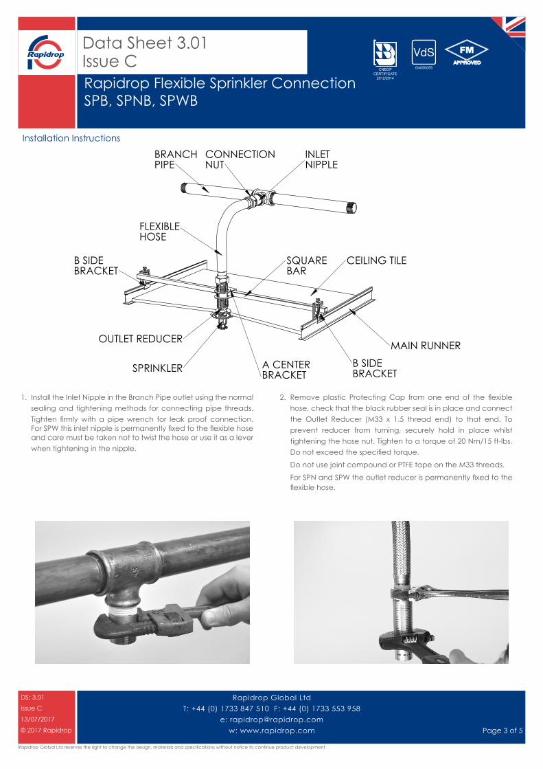
MAIN RUNNER
CEILING TILE
B SIDEBRACKET
B SIDEBRACKET
SPRINKLER
OUTLET REDUCER
A CENTERBRACKET
SQUAREBAR
CONNECTIONNUT
BRANCHPIPE
INLETNIPPLE
FLEXIBLEHOSE
1. Install the Inlet Nipple in the Branch Pipe outlet using the normal sealing and tightening methods for connecting pipe threads. Tighten firmly with a pipe wrench for leak proof connection. For SPW this inlet nipple is permanently fixed to the flexible hose and care must be taken not to twist the hose or use it as a lever when tightening in the nipple.
2. Remove plastic Protecting Cap from one end of the flexible hose, check that the black rubber seal is in place and connect the Outlet Reducer (M33 x 1.5 thread end) to that end. To prevent reducer from turning, securely hold in place whilst tightening the hose nut. Tighten to a torque of 20 Nm/15 ft-lbs. Do not exceed the specified torque.
Do not use joint compound or PTFE tape on the M33 threads.
For SPN and SPW the outlet reducer is permanently fixed to the flexible hose.
Installation Instructions
Rapidrop Global LtdT: +44 (0) 1733 847 510 F: +44 (0) 1733 553 958
e: [email protected] w: www.rapidrop.com Page 4 of 5
Rapidrop Global Ltd reserves the right to change the design, materials and specifications without notice to continue product development
Data Sheet 3.01Issue CRapidrop Flexible Sprinkler ConnectionSPB, SPNB, SPWB
DS: 3.01
Issue C
13/07/2017
© 2017 Rapidrop
FMVdSG4050055CNBOP
CERTIFICATE 2912/2014
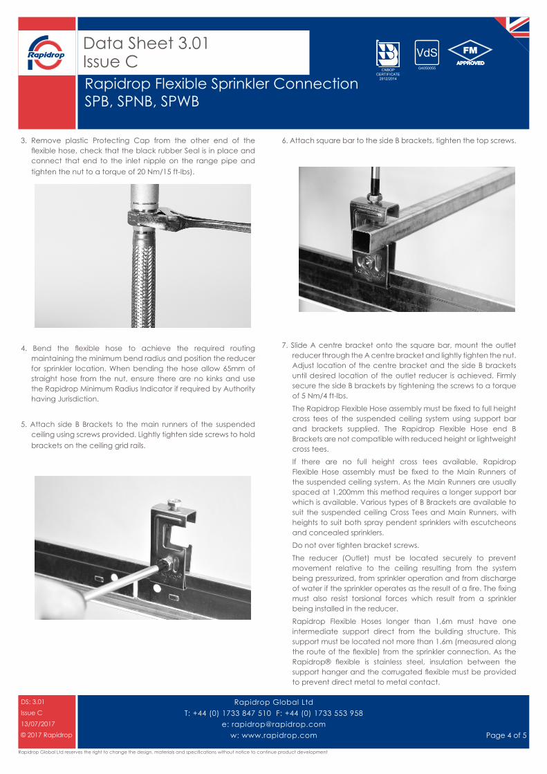
3. Remove plastic Protecting Cap from the other end of the flexible hose, check that the black rubber Seal is in place and connect that end to the inlet nipple on the range pipe and tighten the nut to a torque of 20 Nm/15 ft-lbs).
4. Bend the flexible hose to achieve the required routing maintaining the minimum bend radius and position the reducer for sprinkler location. When bending the hose allow 65mm of straight hose from the nut, ensure there are no kinks and use the Rapidrop Minimum Radius Indicator if required by Authority having Jurisdiction.
5. Attach side B Brackets to the main runners of the suspended ceiling using screws provided. Lightly tighten side screws to hold brackets on the ceiling grid rails.
6. Attach square bar to the side B brackets, tighten the top screws.
7. Slide A centre bracket onto the square bar, mount the outlet reducer through the A centre bracket and lightly tighten the nut. Adjust location of the centre bracket and the side B brackets until desired location of the outlet reducer is achieved. Firmly secure the side B brackets by tightening the screws to a torque of 5 Nm/4 ft-lbs.
The Rapidrop Flexible Hose assembly must be fixed to full height cross tees of the suspended ceiling system using support bar and brackets supplied. The Rapidrop Flexible Hose end B Brackets are not compatible with reduced height or lightweight cross tees.
If there are no full height cross tees available, Rapidrop Flexible Hose assembly must be fixed to the Main Runners of the suspended ceiling system. As the Main Runners are usually spaced at 1,200mm this method requires a longer support bar which is available. Various types of B Brackets are available to suit the suspended ceiling Cross Tees and Main Runners, with heights to suit both spray pendent sprinklers with escutcheons and concealed sprinklers.
Do not over tighten bracket screws.
The reducer (Outlet) must be located securely to prevent movement relative to the ceiling resulting from the system being pressurized, from sprinkler operation and from discharge of water if the sprinkler operates as the result of a fire. The fixing must also resist torsional forces which result from a sprinkler being installed in the reducer.
Rapidrop Flexible Hoses longer than 1,6m must have one intermediate support direct from the building structure. This support must be located not more than 1.6m (measured along the route of the flexible) from the sprinkler connection. As the Rapidrop® flexible is stainless steel, insulation between the support hanger and the corrugated flexible must be provided to prevent direct metal to metal contact.

Rapidrop Global LtdT: +44 (0) 1733 847 510 F: +44 (0) 1733 553 958
e: [email protected] w: www.rapidrop.com Page 5 of 5
Rapidrop Global Ltd reserves the right to change the design, materials and specifications without notice to continue product development
Data Sheet 3.01Issue CRapidrop Flexible Sprinkler ConnectionSPB, SPNB, SPWB
DS: 3.01
Issue C
13/07/2017
© 2017 Rapidrop
FMVdSG4050055CNBOP
CERTIFICATE 2912/2014
8. Apply a non-hardening pipe joint compound or PTFE tape to the male thread of the sprinkler head and install in the Outlet Reducer according to the sprinkler head manufacturer’s instructions, using the wrench supplied by the manufacturer.
When installing the sprinkler head with a two piece escutcheon, the inner piece should be mounted on the thread of the sprinkler head before attaching to the reducer.
9. Adjust height of the Outlet Reducer until desired location of the sprinkler is achieved. Firmly secure the A Centre Bracket by tightening the screws to a torque of 5 Nm/4 ft-lbs).
10. After installation is complete, test the sprinkler system for leaks in accordance with Authority Having Jurisdiction. It is advised to not leave the sprinkler system drained for long periods.