Data Report Project Shoal Area Churchill County, … REPORT PROJECT SHOAL AREA CHURCHILL COUNTY,...
180
DOE/NV--505 UCC-700 DATA REPORT PROJECT SHOAL AREA CHURCHILL COUNTY, NEVADA DOE Nevada Operations Office Las Vegas, Nevada July 1998
Transcript of Data Report Project Shoal Area Churchill County, … REPORT PROJECT SHOAL AREA CHURCHILL COUNTY,...
DOE/NV--505UCC-700
DATA REPORTPROJECT SHOAL AREA
CHURCHILL COUNTY, NEVADA
DOE Nevada Operations OfficeLas Vegas, Nevada
July 1998

DATA REPORTPROJECT SHOAL AREA
CHURCHILL COUNTY, NEVADA
Approved by: Date: Monica Sanchez, Project ManagerOff-Sites Subproject
Approved by: Date: Runore C. Wycoff, Project ManagerNevada Environmental Restoration Project

i
Table of Contents
List of Figures . . . . . . . . . . . . . . . . . . . . . . . . . . . . . . . . . . . . . . . . . . . . . . . . . . . . . . . . . . . . . iii
List of Tables . . . . . . . . . . . . . . . . . . . . . . . . . . . . . . . . . . . . . . . . . . . . . . . . . . . . . . . . . . . . . . ix
List of Acronyms and Abbreviations . . . . . . . . . . . . . . . . . . . . . . . . . . . . . . . . . . . . . . . . . . . . xi
1.0 Introduction . . . . . . . . . . . . . . . . . . . . . . . . . . . . . . . . . . . . . . . . . . . . . . . . . . . . . . . . . . 1-1
1.1 Purpose . . . . . . . . . . . . . . . . . . . . . . . . . . . . . . . . . . . . . . . . . . . . . . . . . . . . . . . . . . 1-1
1.2 Scope of Work . . . . . . . . . . . . . . . . . . . . . . . . . . . . . . . . . . . . . . . . . . . . . . . . . . . . 1-2
2.0 Surface Investigation CAU No. 416 . . . . . . . . . . . . . . . . . . . . . . . . . . . . . . . . . . . . . . . . 2-1
2.1 Purpose . . . . . . . . . . . . . . . . . . . . . . . . . . . . . . . . . . . . . . . . . . . . . . . . . . . . . . . . . . 2-1
2.2 Scope of Work . . . . . . . . . . . . . . . . . . . . . . . . . . . . . . . . . . . . . . . . . . . . . . . . . . . . 2-1
2.3 Summary of Results . . . . . . . . . . . . . . . . . . . . . . . . . . . . . . . . . . . . . . . . . . . . . . . . 2-3
2.4 Estimated Volume of Pit Material . . . . . . . . . . . . . . . . . . . . . . . . . . . . . . . . . . . . . . 2-4
3.0 Subsurface Investigations CAU No. 447 . . . . . . . . . . . . . . . . . . . . . . . . . . . . . . . . . . . . . 3-1
3.1 Scope of Work . . . . . . . . . . . . . . . . . . . . . . . . . . . . . . . . . . . . . . . . . . . . . . . . . . . . 3-1
3.2 Drill Site and Sump Construction . . . . . . . . . . . . . . . . . . . . . . . . . . . . . . . . . . . . . . 3-1
3.3 Summary of Monitoring Well Drilling and Completion Operations . . . . . . . . . . . . . 3-2
4.0 Well HC-1 Summary of Operations . . . . . . . . . . . . . . . . . . . . . . . . . . . . . . . . . . . . . . . . 4-1
4.1 Well HC-1 Geology . . . . . . . . . . . . . . . . . . . . . . . . . . . . . . . . . . . . . . . . . . . . . . . . 4-2
4.2 Well HC-1 Hydrology . . . . . . . . . . . . . . . . . . . . . . . . . . . . . . . . . . . . . . . . . . . . . . 4-2
4.3 Well HC-1 Geophysical Surveys . . . . . . . . . . . . . . . . . . . . . . . . . . . . . . . . . . . . . . . 4-3
4.4 Well HC-1 Radiologic Monitoring . . . . . . . . . . . . . . . . . . . . . . . . . . . . . . . . . . . . . . 4-4
4.5 Well HC-1 Well Construction . . . . . . . . . . . . . . . . . . . . . . . . . . . . . . . . . . . . . . . . . 4-4
4.6 Well HC-1 Sampling . . . . . . . . . . . . . . . . . . . . . . . . . . . . . . . . . . . . . . . . . . . . . . . . 4-4
5.0 Well HC-2 Summary of Operations . . . . . . . . . . . . . . . . . . . . . . . . . . . . . . . . . . . . . . . . 5-1
5.1 Well HC-2 Geology . . . . . . . . . . . . . . . . . . . . . . . . . . . . . . . . . . . . . . . . . . . . . . . . 5-2
5.2 Well HC-2 Hydrology . . . . . . . . . . . . . . . . . . . . . . . . . . . . . . . . . . . . . . . . . . . . . . 5-3
5.3 Well HC-2 Geophysical Surveys . . . . . . . . . . . . . . . . . . . . . . . . . . . . . . . . . . . . . . . 5-3
5.4 Well HC-2 Radiologic Monitoring . . . . . . . . . . . . . . . . . . . . . . . . . . . . . . . . . . . . . . 5-4

Table of Contents (Continued)
ii
5.5 Well HC-2 Well Construction . . . . . . . . . . . . . . . . . . . . . . . . . . . . . . . . . . . . . . . . . 5-4
5.6 Well HC-2 Sampling . . . . . . . . . . . . . . . . . . . . . . . . . . . . . . . . . . . . . . . . . . . . . . . . 5-5
6.0 Well HC-3 Summary of Operations . . . . . . . . . . . . . . . . . . . . . . . . . . . . . . . . . . . . . . . . 6-1
6.1 Well HC-3 Geology . . . . . . . . . . . . . . . . . . . . . . . . . . . . . . . . . . . . . . . . . . . . . . . . 6-3
6.2 Well HC-3 Hydrology . . . . . . . . . . . . . . . . . . . . . . . . . . . . . . . . . . . . . . . . . . . . . . 6-3
6.3 Well HC-3 Geophysical Surveys . . . . . . . . . . . . . . . . . . . . . . . . . . . . . . . . . . . . . . . 6-4
6.4 Well HC-3 Radiologic Monitoring . . . . . . . . . . . . . . . . . . . . . . . . . . . . . . . . . . . . . . 6-5
6.5 Well HC-3 Well Construction . . . . . . . . . . . . . . . . . . . . . . . . . . . . . . . . . . . . . . . . . 6-5
6.6 Well HC-3 Sampling . . . . . . . . . . . . . . . . . . . . . . . . . . . . . . . . . . . . . . . . . . . . . . . . 6-6
7.0 Well HC-4 Summary of Operations . . . . . . . . . . . . . . . . . . . . . . . . . . . . . . . . . . . . . . . . 7-1
7.1 Well HC-4 Geology . . . . . . . . . . . . . . . . . . . . . . . . . . . . . . . . . . . . . . . . . . . . . . . . 7-2
7.2 Well HC-4 Hydrology . . . . . . . . . . . . . . . . . . . . . . . . . . . . . . . . . . . . . . . . . . . . . . . 7-2
7.3 Well HC-4 Geophysical Surveys . . . . . . . . . . . . . . . . . . . . . . . . . . . . . . . . . . . . . . . 7-3
7.4 Well HC-4 Radiologic Monitoring . . . . . . . . . . . . . . . . . . . . . . . . . . . . . . . . . . . . . . 7-3
7.5 Well HC-4 Construction . . . . . . . . . . . . . . . . . . . . . . . . . . . . . . . . . . . . . . . . . . . . . 7-4
7.6 Well HC-4 Sampling . . . . . . . . . . . . . . . . . . . . . . . . . . . . . . . . . . . . . . . . . . . . . . . . 7-4
8.0 Fluid Management . . . . . . . . . . . . . . . . . . . . . . . . . . . . . . . . . . . . . . . . . . . . . . . . . . . . . 8-1
8.1 Summary of Fluid Management . . . . . . . . . . . . . . . . . . . . . . . . . . . . . . . . . . . . . . . . 8-1
8.2 Source Water for Drilling . . . . . . . . . . . . . . . . . . . . . . . . . . . . . . . . . . . . . . . . . . . . 8-1
8.3 Sump Construction . . . . . . . . . . . . . . . . . . . . . . . . . . . . . . . . . . . . . . . . . . . . . . . . . 8-1
8.4 Disposition of Fluids and Current Status of Sumps . . . . . . . . . . . . . . . . . . . . . . . . . 8-2
9.0 Waste Management . . . . . . . . . . . . . . . . . . . . . . . . . . . . . . . . . . . . . . . . . . . . . . . . . . . . 9-1
9.1 NVO-325 Protocols . . . . . . . . . . . . . . . . . . . . . . . . . . . . . . . . . . . . . . . . . . . . . . . . 9-1
9.2 Results of Waste Management Audit . . . . . . . . . . . . . . . . . . . . . . . . . . . . . . . . . . . . 9-1
9.3 Disposition of Waste . . . . . . . . . . . . . . . . . . . . . . . . . . . . . . . . . . . . . . . . . . . . . . . . 9-1
10.0 References . . . . . . . . . . . . . . . . . . . . . . . . . . . . . . . . . . . . . . . . . . . . . . . . . . . . . . . . . 10-1

iii
List of Figures
Number Title Page
1-1 Project Shoal Area Location Map . . . . . . . . . . . . . . . . . . . . . . . . . . . . . . . . . . . . . 1-3
2-1 Shoal Mud Pit Location Map . . . . . . . . . . . . . . . . . . . . . . . . . . . . . . . . . . . . . . . . 2-5
2-2 Shoal Mud Pit Sample Location Map with Upgradient Locations . . . . . . . . . . . . . 2-6
2-3 Shoal Mud Pit Sample Location Map . . . . . . . . . . . . . . . . . . . . . . . . . . . . . . . . . . 2-7
2-4 Cross Section Mud 1 - Borings DP-6, DP-5, DP-4 . . . . . . . . . . . . . . . . . . . . . . . . 2-8
2-5 Cross Section Mud 3 - Borings DP-18, DP-6, DP-3 . . . . . . . . . . . . . . . . . . . . . . . 2-9
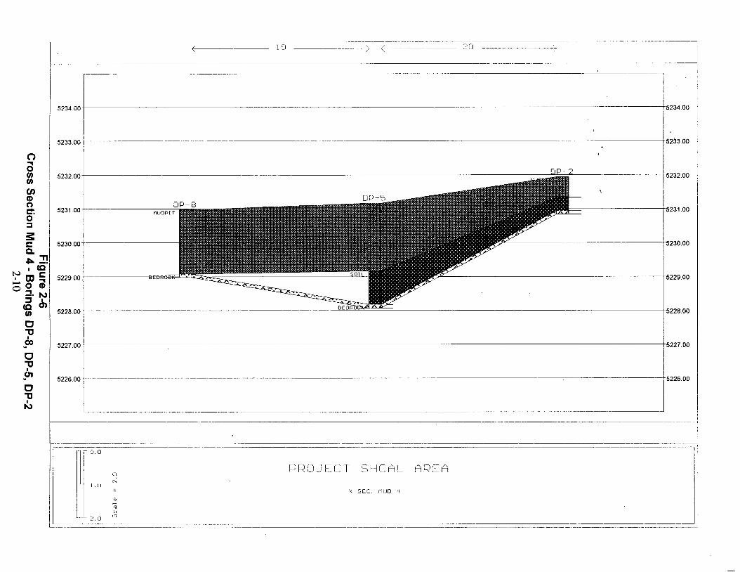
2-6 Cross Section Mud 4 - Borings DP-8, DP-5, DP-2 . . . . . . . . . . . . . . . . . . . . . . . 2-10
2-7 Cross Section Mud 2 - Borings DP-10, DP-9, DP-7, DP-4, DP-1, DP-11 . . . . . . 2-11
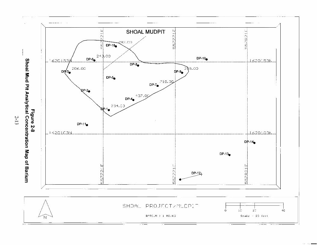
2-8 Shoal Mud Pit Analytical Concentration Map of Barium . . . . . . . . . . . . . . . . . . . 2-13
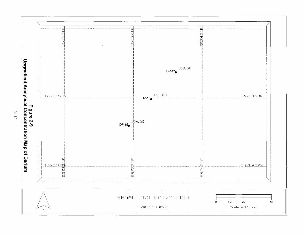
2-9 Upgradient Analytical Concentration Map of Barium . . . . . . . . . . . . . . . . . . . . . 2-14
2-10 Shoal Mud Pit Analytical Concentration Map of Chromium . . . . . . . . . . . . . . . . 2-15
2-11 Upgradient Analytical Concentration Map of Chromium . . . . . . . . . . . . . . . . . . . 2-16
2-12 Shoal Mud Pit Analytical Concentration Map of Gross Alpha . . . . . . . . . . . . . . . 2-17
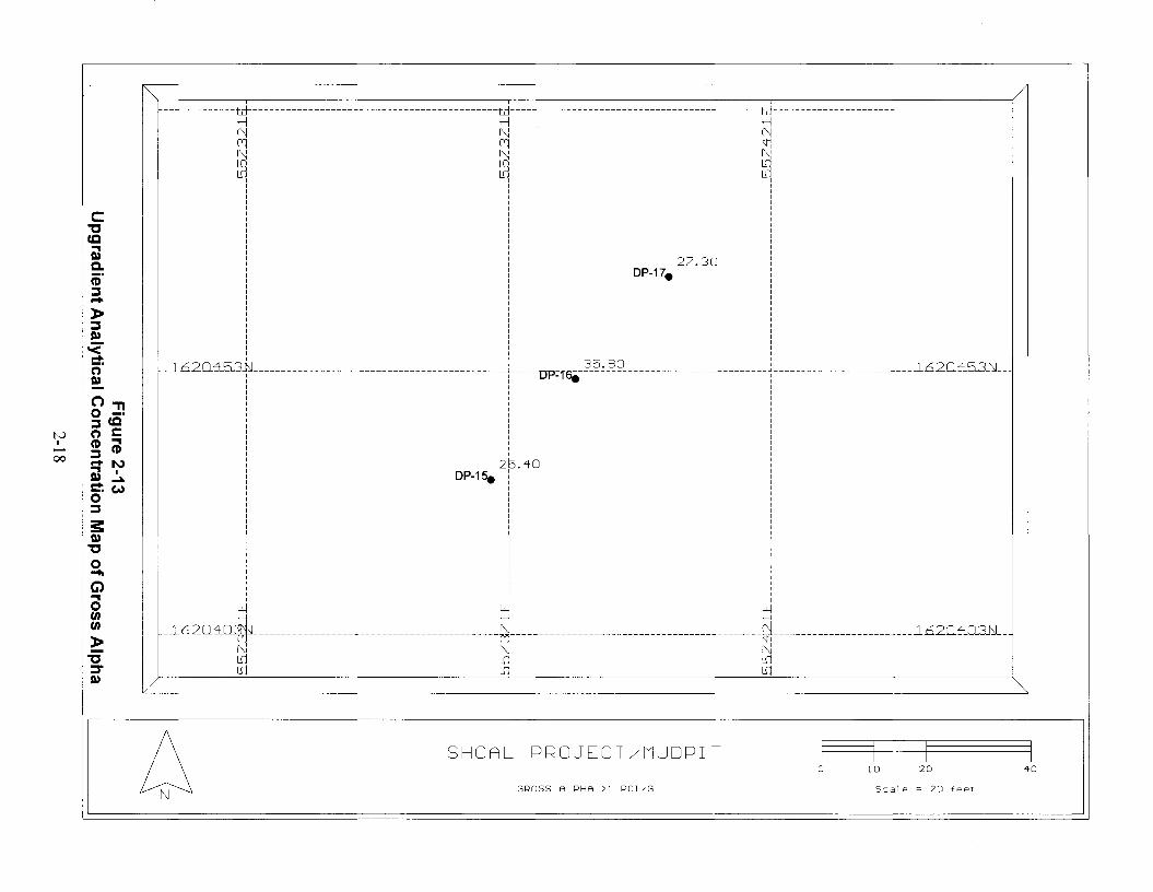
2-13 Upgradient Analytical Concentration Map of Gross Alpha . . . . . . . . . . . . . . . . . 2-18
2-14 Shoal Mud Pit Analytical Concentration Map of Gross Beta . . . . . . . . . . . . . . . . 2-19
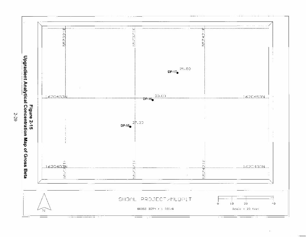
2-15 Upgradient Analytical Concentration Map of Gross Beta . . . . . . . . . . . . . . . . . . 2-20

List of Figures (Continued)
Number Title Page
iv
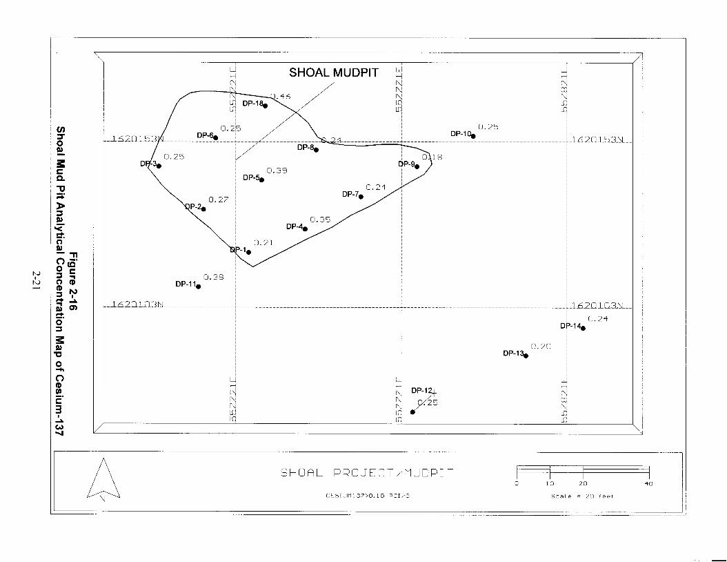
2-16 Shoal Mud Pit Analytical Concentration Map of Cesium-137 . . . . . . . . . . . . . . . 2-21
2-17 Upgradient Analytical Concentration Map of Cesium-137 . . . . . . . . . . . . . . . . . 2-22
2-18 Shoal Mud Pit Analytical Concentration Map of TPH Diesel . . . . . . . . . . . . . . . 2-23
2-19 Shoal Mud Pit Analytical Concentration Map of Waste Oil . . . . . . . . . . . . . . . . . 2-24
2-20 Soil Boring Log for DP-1 . . . . . . . . . . . . . . . . . . . . . . . . . . . . . . . . . . . . . . . . . . 2-25
2-21 Soil Boring Log for DP-2 . . . . . . . . . . . . . . . . . . . . . . . . . . . . . . . . . . . . . . . . . . 2-26
2-22 Soil Boring Log for DP-3 . . . . . . . . . . . . . . . . . . . . . . . . . . . . . . . . . . . . . . . . . . 2-27
2-23 Soil Boring Log for DP-4 . . . . . . . . . . . . . . . . . . . . . . . . . . . . . . . . . . . . . . . . . . 2-28
2-24 Soil Boring Log for DP-5 . . . . . . . . . . . . . . . . . . . . . . . . . . . . . . . . . . . . . . . . . . 2-29
2-25 Soil Boring Log for DP-6 . . . . . . . . . . . . . . . . . . . . . . . . . . . . . . . . . . . . . . . . . . 2-30
2-26 Soil Boring Log for DP-7 . . . . . . . . . . . . . . . . . . . . . . . . . . . . . . . . . . . . . . . . . . 2-31
2-27 Soil Boring Log for DP-8 . . . . . . . . . . . . . . . . . . . . . . . . . . . . . . . . . . . . . . . . . . 2-32
2-28 Soil Boring Log for DP-9 . . . . . . . . . . . . . . . . . . . . . . . . . . . . . . . . . . . . . . . . . . 2-33
2-29 Soil Boring Log for DP-10 . . . . . . . . . . . . . . . . . . . . . . . . . . . . . . . . . . . . . . . . . 2-34
2-30 Soil Boring Log for DP-11 . . . . . . . . . . . . . . . . . . . . . . . . . . . . . . . . . . . . . . . . . 2-35
2-31 Soil Boring Log for DP-12 . . . . . . . . . . . . . . . . . . . . . . . . . . . . . . . . . . . . . . . . . 2-36
List of Figures (Continued)
Number Title Page
v
2-32 Soil Boring Log for DP-13 . . . . . . . . . . . . . . . . . . . . . . . . . . . . . . . . . . . . . . . . . 2-37
2-33 Soil Boring Log for DP-14 . . . . . . . . . . . . . . . . . . . . . . . . . . . . . . . . . . . . . . . . . 2-38
2-34 Soil Boring Log for DP-15 . . . . . . . . . . . . . . . . . . . . . . . . . . . . . . . . . . . . . . . . . 2-39
2-35 Soil Boring Log for DP-16 . . . . . . . . . . . . . . . . . . . . . . . . . . . . . . . . . . . . . . . . . 2-40
2-36 Soil Boring Log for DP-17 . . . . . . . . . . . . . . . . . . . . . . . . . . . . . . . . . . . . . . . . . 2-41
2-37 Soil Boring Log for DP-18 . . . . . . . . . . . . . . . . . . . . . . . . . . . . . . . . . . . . . . . . . 2-42
3-1 Shoal Well Location Map . . . . . . . . . . . . . . . . . . . . . . . . . . . . . . . . . . . . . . . . . . . 3-4
3-2 Shoal Project Well Cross Section Location . . . . . . . . . . . . . . . . . . . . . . . . . . . . . . 3-5
3-3 Shoal Flow Gradient Cross Section . . . . . . . . . . . . . . . . . . . . . . . . . . . . . . . . . . . 3-6
4-1 Summary of Well HC-1 Drilling Parameters . . . . . . . . . . . . . . . . . . . . . . . . . . . . . 4-5
4-2 Well HC-1 Lithologic Descriptions . . . . . . . . . . . . . . . . . . . . . . . . . . . . . . . . . . . . 4-6
4-3 HC-1 Fluid Injection versus Production Diagram . . . . . . . . . . . . . . . . . . . . . . . . . 4-8
4-4 HC-1 Geophysical Log Traces of Spectra Gamma Ray . . . . . . . . . . . . . . . . . . . . . 4-9
4-5 HC-1 Geophysical Log Traces of Caliper, Resistivity, Neutron . . . . . . . . . . . . . . 4-10
4-6 HC-1 Geophysical Log Traces of Caliper, Gamma Ray, Density . . . . . . . . . . . . . 4-11
4-7 HC-1 Geophysical Log Traces of Chemtool . . . . . . . . . . . . . . . . . . . . . . . . . . . . 4-12

List of Figures (Continued)
Number Title Page
vi
4-8 HC-1 Tritium Concentrations During Drilling . . . . . . . . . . . . . . . . . . . . . . . . . . . 4-13
4-9 HC-1 Subsurface Well Completion Diagram . . . . . . . . . . . . . . . . . . . . . . . . . . . . 4-14
4-10 HC-1 Well Head Completion Diagram . . . . . . . . . . . . . . . . . . . . . . . . . . . . . . . . 4-15
5-1 Summary of Well HC-2 Drilling Parameters . . . . . . . . . . . . . . . . . . . . . . . . . . . . . 5-6
5-2 Well HC-2 Lithologic Descriptions . . . . . . . . . . . . . . . . . . . . . . . . . . . . . . . . . . . . 5-7
5-3 HC-2 Fluid Injection versus Production Diagram . . . . . . . . . . . . . . . . . . . . . . . . . 5-9
5-4 HC-2 Geophysical Log Traces of Spectra Gamma Ray . . . . . . . . . . . . . . . . . . . . 5-10
5-5 HC-2 Geophysical Log Traces of Caliper, Resistivity, Neutron . . . . . . . . . . . . . . 5-11
5-6 HC-2 Geophysical Log Traces of Caliper, Gamma Ray, Density . . . . . . . . . . . . . 5-12
5-7 HC-2 Geophysical Log Traces of Chemtool . . . . . . . . . . . . . . . . . . . . . . . . . . . . 5-13
5-8 HC-2 Tritium Concentrations During Drilling . . . . . . . . . . . . . . . . . . . . . . . . . . . 5-14
5-9 HC-2 Subsurface Well Completion Diagram . . . . . . . . . . . . . . . . . . . . . . . . . . . . 5-15
5-10 HC-2 Well Head Completion Diagram . . . . . . . . . . . . . . . . . . . . . . . . . . . . . . . . 5-16
6-1 Summary of Well HC-3 Drilling Parameters . . . . . . . . . . . . . . . . . . . . . . . . . . . . . 6-7
6-2 Well HC-3 Lithologic Descriptions . . . . . . . . . . . . . . . . . . . . . . . . . . . . . . . . . . . . 6-8
6-3 HC-3 Fluid Injection versus Production Diagram . . . . . . . . . . . . . . . . . . . . . . . . 6-10

List of Figures (Continued)
Number Title Page
vii
6-4 HC-3 Geophysical Log Traces of Spectra Gamma Ray . . . . . . . . . . . . . . . . . . . . 6-11
6-5 HC-3 Geophysical Log Traces of Caliper, Resistivity, Neutron . . . . . . . . . . . . . . 6-12
6-6 HC-3 Geophysical Log Traces of Caliper, Gamma Ray, Density . . . . . . . . . . . . . 6-13
6-7 HC-3 Tritium Concentrations During Drilling . . . . . . . . . . . . . . . . . . . . . . . . . . . 6-14
6-8 HC-3 Subsurface Well Completion Diagram . . . . . . . . . . . . . . . . . . . . . . . . . . . . 6-15
6-9 HC-3 Well Head Completion Diagram . . . . . . . . . . . . . . . . . . . . . . . . . . . . . . . . 6-16
7-1 Summary of Well HC-4 Drilling Parameters . . . . . . . . . . . . . . . . . . . . . . . . . . . . . 7-5
7-2 Well HC-4 Lithologic Descriptions . . . . . . . . . . . . . . . . . . . . . . . . . . . . . . . . . . . . 7-6
7-3 HC-4 Fluid Injection versus Production Diagram . . . . . . . . . . . . . . . . . . . . . . . . . 7-8
7-4 HC-4 Geophysical Log Traces of Spectra Gamma Ray . . . . . . . . . . . . . . . . . . . . . 7-9
7-5 HC-4 Geophysical Log Traces of Caliper, Resistivity, Neutron . . . . . . . . . . . . . . 7-10
7-6 HC-4 Geophysical Log Traces of Caliper, Gamma Ray, Density . . . . . . . . . . . . . 7-11
7-7 HC-4 Geophysical Log Traces of Chemtool . . . . . . . . . . . . . . . . . . . . . . . . . . . . 7-12
7-8 HC-4 Tritium Concentrations During Drilling . . . . . . . . . . . . . . . . . . . . . . . . . . . 7-13
7-9 HC-4 Subsurface Well Completion Diagram . . . . . . . . . . . . . . . . . . . . . . . . . . . . 7-14
7-10 HC-4 Well Head Completion Diagram . . . . . . . . . . . . . . . . . . . . . . . . . . . . . . . . 7-15

List of Figures (Continued)
Number Title Page
viii
8-1 Diagram of Single-Lined Sump Construction . . . . . . . . . . . . . . . . . . . . . . . . . . . . 8-3
8-2 Diagram of Double-Lined Sump Construction . . . . . . . . . . . . . . . . . . . . . . . . . . . 8-4

ix
List of Tables
Number Title Page
2-1 Summary of Shoal Direct Push Samples . . . . . . . . . . . . . . . . . . . . . . . . . . . . . . . 2-43
2-2 Shoal Mud Pit Analytical Data . . . . . . . . . . . . . . . . . . . . . . . . . . . . . . . . . . . . . . 2-44
2-3a and 2-3b Shoal Mud Pit Quality Control Sample Data . . . . . . . . . . . . . . . . . . . . . . . . . . . . 2-47
4-1 Well HC-1 Lithium Bromide Concentrations . . . . . . . . . . . . . . . . . . . . . . . . . . . 4-16
4-2 Well HC-1 Water Level Measurements . . . . . . . . . . . . . . . . . . . . . . . . . . . . . . . . 4-19
4-3 Well HC-1 List of Geophysical Logs . . . . . . . . . . . . . . . . . . . . . . . . . . . . . . . . . 4-20
4-4 HC-1 Summary of Subsurface Investigation Samples . . . . . . . . . . . . . . . . . . . . . 4-21
4-5a to 4-5e HC-1 Sample Results . . . . . . . . . . . . . . . . . . . . . . . . . . . . . . . . . . . . . . . . . . . . . 4-22
5-1 HC-2 Lithium Bromide Concentrations . . . . . . . . . . . . . . . . . . . . . . . . . . . . . . . 5-17
5-2 HC-2 Water Level Measurements . . . . . . . . . . . . . . . . . . . . . . . . . . . . . . . . . . . . 5-18
5-3 HC-2 List of Geophysical Logs . . . . . . . . . . . . . . . . . . . . . . . . . . . . . . . . . . . . . 5-19
5-4 HC-2 Summary of Subsurface Investigation Samples . . . . . . . . . . . . . . . . . . . . . 5-20
5-5a to 5-5f HC-2 Sample Results . . . . . . . . . . . . . . . . . . . . . . . . . . . . . . . . . . . . . . . . . . . . . 5-21
6-1 HC-3 Lithium Bromide Concentrations . . . . . . . . . . . . . . . . . . . . . . . . . . . . . . . 6-17
6-2 Well HC-3 Water Level Measurements . . . . . . . . . . . . . . . . . . . . . . . . . . . . . . . . 6-18
6-3 Well HC-3 List of Geophysical Logs . . . . . . . . . . . . . . . . . . . . . . . . . . . . . . . . . 6-19

List of Tables (Continued)
Number Title Page
x
6-4 HC-3 Summary of Subsurface Investigation Samples . . . . . . . . . . . . . . . . . . . . . 6-20
6-5a to 6-5e HC-3 Sample Results . . . . . . . . . . . . . . . . . . . . . . . . . . . . . . . . . . . . . . . . . . . . . 6-21
7-1 HC-4 Lithium Bromide Concentrations . . . . . . . . . . . . . . . . . . . . . . . . . . . . . . . 7-16
7-2 HC-4 Water Level Measurements . . . . . . . . . . . . . . . . . . . . . . . . . . . . . . . . . . . . 7-17
7-3 HC-4 List of Geophysical Logs . . . . . . . . . . . . . . . . . . . . . . . . . . . . . . . . . . . . . 7-18
7-4 HC-4 Summary of Subsurface Investigation Samples . . . . . . . . . . . . . . . . . . . . . 7-19
7-5a to 7-5f HC-4 Sample Results . . . . . . . . . . . . . . . . . . . . . . . . . . . . . . . . . . . . . . . . . . . . . 7-20
8-1 Well HC-1 ER Fluid Disposition Status Reporting Form . . . . . . . . . . . . . . . . . . . 8-5
8-2 Well HC-2 ER Fluid Disposition Status Reporting Form . . . . . . . . . . . . . . . . . . . 8-6
8-3 Well HC-3 ER Fluid Disposition Status Reporting Form . . . . . . . . . . . . . . . . . . . 8-7
8-4 Well HC-4 ER Fluid Disposition Status Reporting Form . . . . . . . . . . . . . . . . . . . 8-8

xi
List of Acronyms and Abbreviations
AIP Analysis in process
bgs Below ground surface
CAIP Corrective Action Investigation Plan(s)
CAS Corrective Action Site(s)
CAU Corrective Action Unit(s)
CFR Code of Federal Regulations
cm Centimeter(s)
COC Chain of Custody
DOE U.S. Department of Energy
DOE/NV U.S. Department of Energy, Nevada Operations Office
DRI Desert Research Institute
FFACO Federal Facility Agreement And Consent Order
FMP Fluid Management Plan
ft Foot (feet)
ft Cubic foot (feet)3
gpm Gallon(s) per minute
id Inside diameter
in. Inch(es)
IT IT Corporation
L/min Liter(s) per minute
LiBr Lithium Bromide
m Meter(s)
m Cubic meter(s)3
MCL Maximum Contaminate Level(s)
min/ft Minutes per foot (feet)
mg/kg Milligram(s) per kilogram
mg/L Milligram(s) per liter
MSDS Material Safety Data Sheet(s)
NA Not Analyzed
ND Not detected
NDEP Nevada Division of Environmental Protection
NDWS Nevada Drinking Water Standards
NTS Nevada Test Site
od Outside diameter

List of Acronyms and Abbreviations (Continued)
xii
pCi/L PicoCurie(s) per Liter
PS Post Shot
PSA Project Shoal Area
psi Pound(s) per square inch
QC Quality control
SGZ Surface Ground Zero
SSHASP Site-Specific Health and Safety Plan
SVOC Semivolatile organic compound(s)
TCLP Toxicity Characteristic Leaching Procedure
TD Total depth
TPH Total Petroleum Hydrocarbon(s)
VOC Volatile organic compound(s)
Xe Xenon
EC Degree(s) Celsius

1-1
1.0 Introduction
This preliminary data report presents the field data collected by IT Corporation (IT) between
September 4 and November 14, 1996, as part of the implementation of the Corrective Action
Investigation Plan (CAIP) for the Project Shoal Area, CAU No. 416 (PSA) (DOE/NV, 1996a).
The CAIP is part of an ongoing U.S. Department of Energy (DOE)-funded project for the
investigation of Corrective Action Units (CAU) No. 416 surface and No. 447 subsurface, PSA.
All work conducted on this project was conducted in accordance with the Federal Facility
Agreement and Consent Order (FFACO) of 1996, the Resource Conservation and Recovery Act
Industrial Sites Quality Assurance Plan (DOE, 1994) and all applicable Nevada Division of
Environmental Protection (NDEP) policies and regulations (NDEP, 1992).
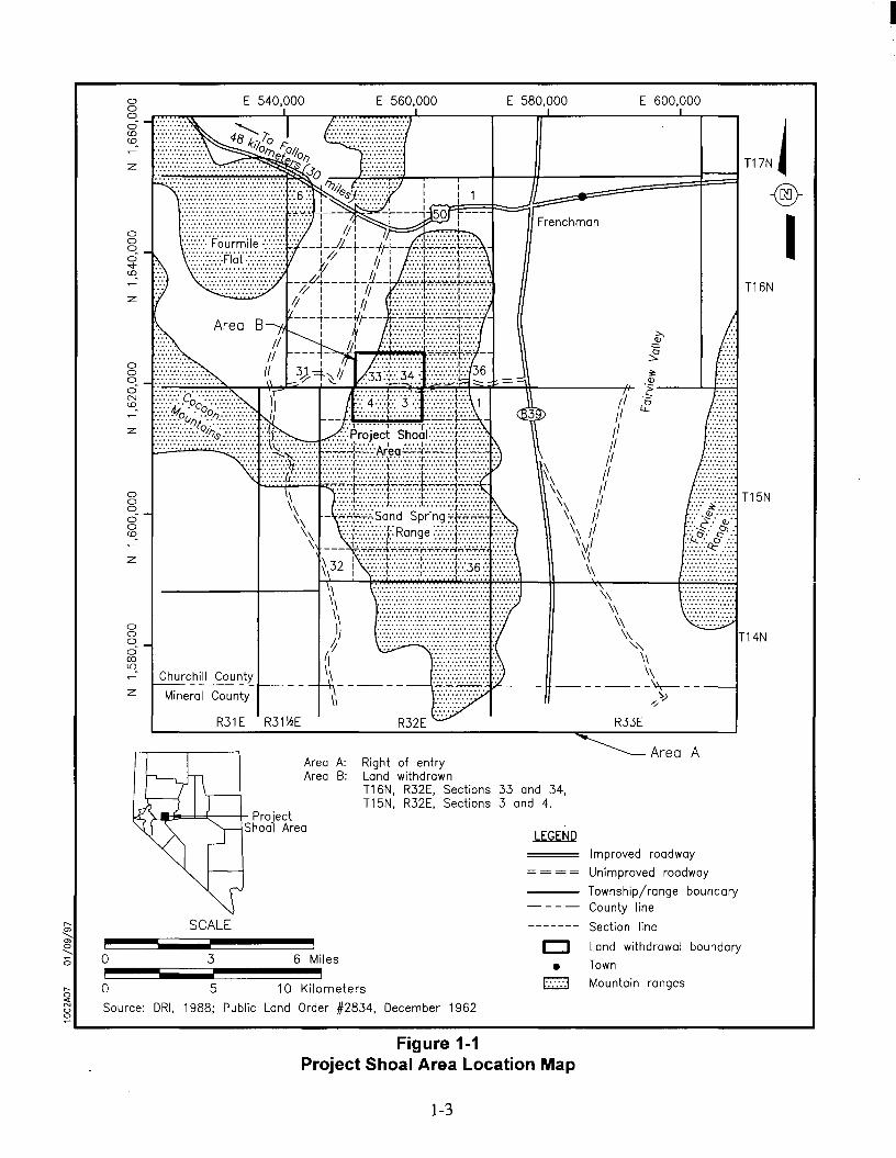
The PSA covers 10.36 square kilometers (4.0 square miles) and is located in northwestern
Nevada approximately 48.28 kilometers (30.0 miles) southeast of the town of Fallon, in the
northern portion of the Sand Springs Range in Churchill County, Nevada (Figure 1-1). The PSA
was active during the early to mid-1960s as the site of a single underground nuclear test,
Project Shoal. The test was conducted to determine whether seismic waves produced from an
underground nuclear test could be differentiated from those resulting from earthquakes.
1.1 PurposeThe purpose of this field investigation was to investigate surface and subsurface areas possibly
contaminated by the Project Shoal Nuclear Test and associated activities. The purpose of the
surface investigation was to determine if drilling materials contained within the PSA mud pit were
contaminated and, if so, to determine the nature and extent of contamination. The results of this
surface investigation would be used to develop an appropriate corrective action for CAU
No. 416.
The purpose of the subsurface investigation was to collect aquifer and groundwater data to aid in
the modeling of groundwater flow and contaminant transport. The resulting model will be used to
establish the boundary for CAU No. 447.

1-2
1.2 Scope of WorkThe scope of the surface investigation included soil sampling from the mud pit and surrounding
area. Twelve soil borings were advanced within the mud pit; three soil borings were advanced
upgradient; and three were advanced downgradient of the mud pit. Discrete soil samples were
obtained from individual borings to characterize mud pit material, natural soils, and bedrock
below and proximal to the mud pit.
The scope of the subsurface investigation included constructing drill pads and lined fluid storage
sumps for drilling, drilling four groundwater monitoring wells to depths in excess of
396.24 meters (m) (1,300 feet [ft]) below ground surface (bgs), collecting hydrologic data during
drilling, regularly monitoring discharged drilling effluent for radionuculides, conducting downhole
geophysical logging of the open boreholes, casing the boreholes above the potentiometric surface,
developing the wells, and collecting groundwater samples from the developed wells. Upon
completing drilling and casing operations, water levels were monitored to determine recovery
rates and the static water level of each well.
I
T16N
T14N
::::::::::. T15N
\~~~......................................................................................
Area A
E 600,000
R33E
Frenchman
o Land withdrawal boundary
• Town
('::::.1 Mountain ranges
Improved roadway
Unimproved roadway
--- Township/range boundaryCounty line
Section line
E 580,000E 560,000
Area A: Right of entryArea B: Land withdrawn
T16N, R32E, Sections 33 and 34,T15N, R32E, Sections 3 and 4.
E 540,000
R31E R31~E
Churc_h~1 Cou'2.t~
Mineral County
)...JI~='=:l:;:--t- ProjectShoal Area
z
z
z
z
ooc:ooCD
z
oooc5'¢CD
ooo. -.r~~r------;r--....,.~~.............rrr'----""--"""TT".L..-_------""""....---,°CDCD
oooc5NCD
ooo.ocoLO.
r-- SCALE'"<,
'"0<,0 3 6 Miles0
i ir-, 0 5 10 Kilometers0-c
Land Order #2834,N Source: DRI, 1988; Public December 19620
~
Figure 1-1Project Shoal Area Location Map
1-3

This page intentionally left blank

2-1
2.0 Surface Investigation CAU No. 416
The Shoal Mud Pit, Corrective Action Site (CAS) Number 57-09-01, is located due east of
surface ground zero in a shallow canyon with an earthen dam at the southern end (Figure 2-1).
The Shoal Mud Pit was constructed to hold fluids and cuttings from the Post Shot (PS)-1 vertical
borehole that was drilled into the Shoal test cavity in October 1963. Since PS-1 was drilled using
bentonite drilling mud, air, and air-mist, the primary constituents of concern in the mud pit are
possible radiological contaminants from the Shoal test cavity. Some details of the Shoal test are
still classified; however, the known nonclassified radiological contaminants of concern are tritium,
strontium , and cesium . Short-lived gaseous radioisotopes of iodine , xenon (Xe ), and90 137 131 133m 133m
Xe , encountered during the drilling of the post shot, have decayed to below detection limits. 133
These radioisotopes were not detected in the samples colleted during the September 1996
sampling event.
Please note that Figures 2-1 to 2-37 and Tables 2-1 to 2-3, cited in the following text, are located
at the end of this section.
2.1 PurposeThe purpose of sampling the Project Shoal Area mud pit was to evaluate potential contamination
and to determine the vertical and horizontal extent of the mud pit. Eighteen locations were
sampled in and around the mud pit by the direct-push method (Figure 2-2).
2.2 Scope of WorkThe mud pit characterization activity was conducted from September 5 through 8, 1996, and
September 15 and 16, 1996. Gregg Drilling Company of Signal Hill, California, was
subcontracted to do the direct-push borings, under the direction of IT.
Before sampling the mud pit, a control point was established at the approximate middle of the
earthen dam, and sample locations were measured out in a 6.10-m (20.0-ft) grid pattern within the
mud pit. A total of ten soil borings (DP-1 to DP-9, and DP-18) were taken to characterize the
mud pit. Three soil borings (DP-12, DP-13, and DP-14) were taken downgradient on the south
side of the earthen dam; three (DP-15, DP-16, and DP-17) were taken from approximately
152.40-m (500.0-ft) upgradient in the canyon; and one boring each was taken from outside the
east (DP-10) and west (DP-11) edges of the mud pit (Figure 2-2).

2-2
Soil borings were completed using direct-push techniques. This method incorporates a hydraulic
percussion hammer which drives a 0.61-m (2.0-ft) long sampling rod to the required depth. The
rod is hollow with four 15.24-centimeter (cm) (6.0-inch [in.]) long, 2.54-cm (1.0-in.) diameter,
stainless steel sampling sleeves. The soil is forced into the sleeves as the hammer drives the
sampler into the ground. When the sampling sleeves were removed from the drive rod, the ends
of each 15.24-cm (6.0-in.) long sleeve were inspected and logged by the IT site geologist. A cap
was placed on each end of the sampling sleeve until the boring was completed and the soil in the
sleeves could be composited for sampling. After the soil was composited, it was placed in the
sample jars, labeled, and placed on ice. Samples were handled according to ITLV Standard
Quality Practices (IT, 1996).
A composite sample was collected from all material recovered from each direct-push sampling
location. In order to obtain adequate sample volume, it was necessary to advance more than one
boring at a location; the additional borings were done within a 30.5-cm (1.0-ft) radius of the initial
boring. The sample sleeves were only 2.54 cm (1.0 in.) in diameter, and the maximum push depth
was less than 1.22 m (4.0-ft).
The soil borings revealed that the mud pit has a maximum thickness of 0.61 m (2.0 ft) in the
center and thins towards the edges. The direct-push sampling rod was usually refused when the
granite bedrock was encountered at a depth of generally less than 1.22-m (4.0-ft) below the mud
pit’s surface. There was no obvious contact between the mud pit floor and the native soil. Mud
pit material was distinguished from the background soil based on a change in grain size and
material color. Where samples were required to analyze the soil below the mud pit, a composite
sample was collected from the deepest sample sleeves that contained only native soil and no mud
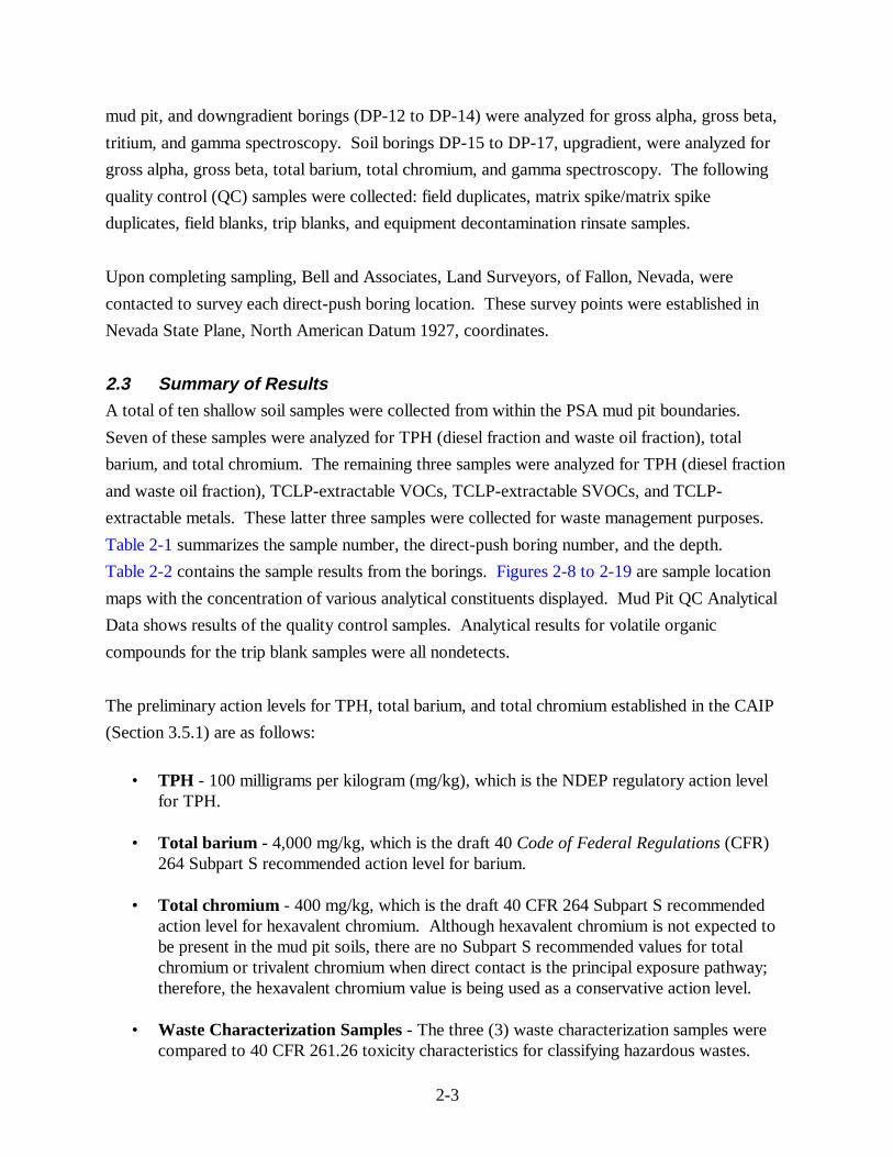
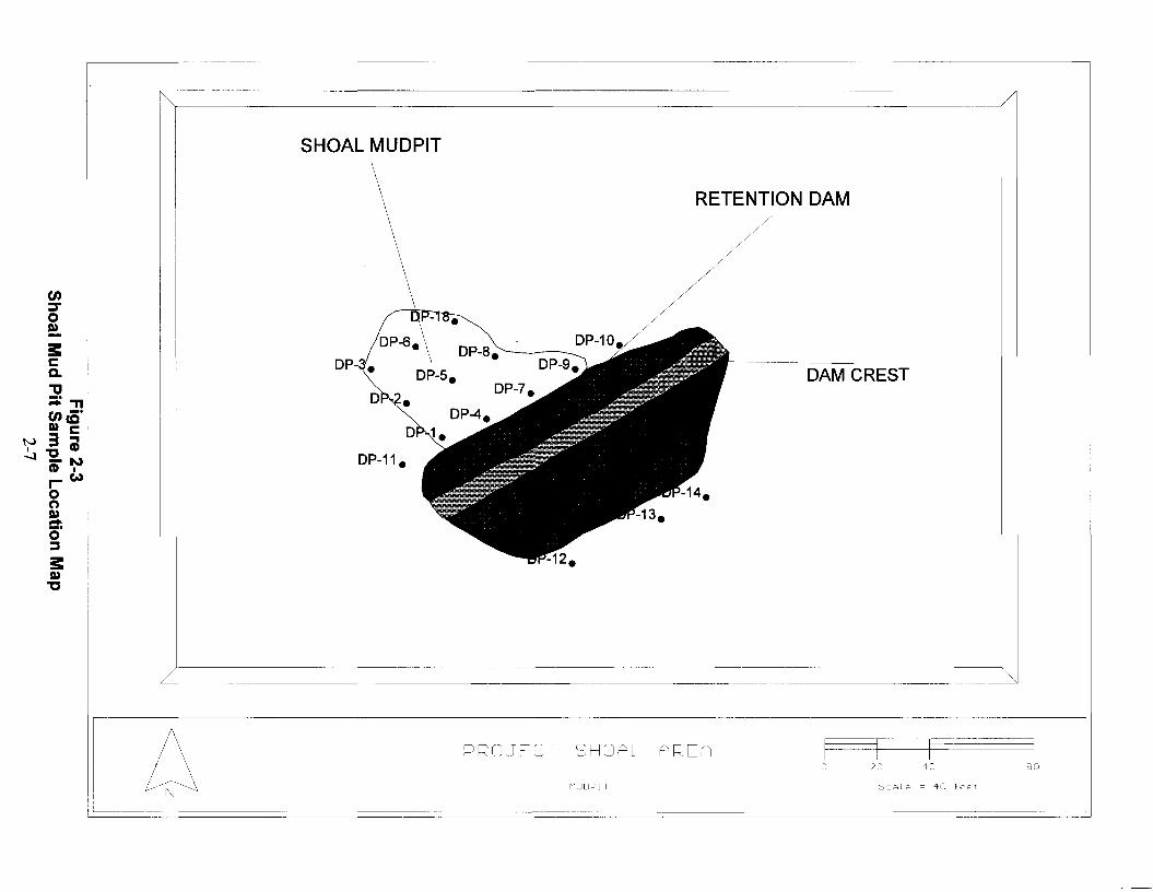
pit material. Soil boring logs for direct-push borings DP-1 through DP-18 are illustrated in
Figures 2-20 through 2-37. Figure 2-3 is a plan view of the mud pit showing sampling locations,
and Figures 2-4 through 2-7 are cross sections of the mud pit.
Shallow mud pit samples DP-1, DP-3, DP-4, DP-6, DP-7, DP-9, and DP-18 were analyzed for
gross alpha, gross beta, total barium, total chromium, tritium, gamma spectroscopy, and Total
Petroleum Hydrocarbon (TPH) diesel. Deep mud pit samples (DP-1, DP-5, DP-7, DP-9, and
DP-18) were analyzed for gross alpha, gross beta, tritium, and gamma spectroscopy. Soil boring
locations DP-2, DP-5, and DP-8 were waste management samples and were analyzed for gross
alpha, gross beta, Toxicity Characteristic Leaching Procedure (TCLP) metals, tritium, gamma
spectroscopy, TPH diesel, TCLP semivolatile organic compounds (SVOCs), and TCLP volatile
organic compounds (VOCs). Direct-push borings (DP-10 and DP-11), which are adjacent to the
2-3
mud pit, and downgradient borings (DP-12 to DP-14) were analyzed for gross alpha, gross beta,
tritium, and gamma spectroscopy. Soil borings DP-15 to DP-17, upgradient, were analyzed for
gross alpha, gross beta, total barium, total chromium, and gamma spectroscopy. The following
quality control (QC) samples were collected: field duplicates, matrix spike/matrix spike
duplicates, field blanks, trip blanks, and equipment decontamination rinsate samples.
Upon completing sampling, Bell and Associates, Land Surveyors, of Fallon, Nevada, were
contacted to survey each direct-push boring location. These survey points were established in
Nevada State Plane, North American Datum 1927, coordinates.
2.3 Summary of ResultsA total of ten shallow soil samples were collected from within the PSA mud pit boundaries.
Seven of these samples were analyzed for TPH (diesel fraction and waste oil fraction), total
barium, and total chromium. The remaining three samples were analyzed for TPH (diesel fraction
and waste oil fraction), TCLP-extractable VOCs, TCLP-extractable SVOCs, and TCLP-
extractable metals. These latter three samples were collected for waste management purposes.
Table 2-1 summarizes the sample number, the direct-push boring number, and the depth.
Table 2-2 contains the sample results from the borings. Figures 2-8 to 2-19 are sample location
maps with the concentration of various analytical constituents displayed. Mud Pit QC Analytical
Data shows results of the quality control samples. Analytical results for volatile organic
compounds for the trip blank samples were all nondetects.
The preliminary action levels for TPH, total barium, and total chromium established in the CAIP
(Section 3.5.1) are as follows:
• TPH - 100 milligrams per kilogram (mg/kg), which is the NDEP regulatory action levelfor TPH.
• Total barium - 4,000 mg/kg, which is the draft 40 Code of Federal Regulations (CFR)264 Subpart S recommended action level for barium.
• Total chromium - 400 mg/kg, which is the draft 40 CFR 264 Subpart S recommendedaction level for hexavalent chromium. Although hexavalent chromium is not expected tobe present in the mud pit soils, there are no Subpart S recommended values for totalchromium or trivalent chromium when direct contact is the principal exposure pathway;therefore, the hexavalent chromium value is being used as a conservative action level.
• Waste Characterization Samples - The three (3) waste characterization samples werecompared to 40 CFR 261.26 toxicity characteristics for classifying hazardous wastes.
2-4
The analysis for TPH found waste oil in several samples above the State regulatory limit of
100 mg/kg, while TPH diesel was found above this limit in only two samples (see Table 2-2).
However, the total barium and total chromium levels are well below the proposed Subpart S
action levels. None of the analyses for the radiological parameters showed levels above expected
background. In addition, the waste characterization sample analyses show that the material is not
a hazardous waste.
2.4 Estimated Volume of Pit MaterialThe estimated volume of material in the mud pit is approximately 116.21 cubic meters
(4,104 cubic feet). The volume was estimated by averaging the depth of the mud pit, 1.52 ft
(as encountered in the borings), and multiplying by 2,700 square feet, the estimated surface area
of the mud pit. Refer to Figures 2-3 to 2-7 as they illustrate the approximate subsurface extent of
the impoundment and the irregular basal contour.

kE;GEND
I
Source: DOE, 1996
o
o
SCALE
0.6 1.2 Kilometers
i0.25 0.5 Miles
@ Abandoned well or boring
• Proposed well (approximate location)
* Shoal Mud Pit (approximate location)
- Withdrawn area boundary
--- Topographic contour (Interval =200 feet)
x5365 Point elevation
• - - Unpaved road
xSGZ Surface ground zero
- - - Approximate location of groundwater divide
Figure 2-1Shoal Mud Pit Location Map
2-5

....... L62040lSN
DAM CREST----------+--
.................................. r 16201.0,6N..
........................... ...L62020.6N.....
, ,, ,, ,, ,, ,, ,, ,, ,, ,
SHOAL MUDPIT
LJ LJ~ ~C1 DP-17. MM ~N DP-lIL NlSi .... lSilSi DP-15. lSi
----------------------------_.._-_._-------
RETENTION DAM....1.6.2.02Q.6.N " " _ .
16201.66N ....................1 .._ _................... , .
162.0.1lJl6N " .
Wrl
...1.6.2.0.aq.6.N -.-- 0'1 '"1 .(YJ '"1M ~ lSi ~ NN N N N NlSi lSi lSi lSi lSilSi lSi lSi lSi lSi
en::r0II)
3:cQ.
"'tI;:;:enII)
3"CCD..0oII) "T1- _.-'CCo C
N ~ ...I 3: CD0'1
II) N"C I
N:e;:;:::rC
"CccAlQ.C;'~-..0(')II)-c)"~(fJ
._.._.__._- ._========-Sc e Le = 100
I /\ PROJECT SHOAL AREA
L!='N=\=================.===S=AM=P=LE 1_ OeATI ON MAP
o 50 100
feet
200
SHOAL MUDPIT
DAM CREST
RETENTION DAM
.__._----------------------------"
•
D
•D
DP-11.
)--------------------------------------------------\
._----_._----------------
===============~---
Scale = 40 feet
804020o
MUDPI T
PROJECT SHOAL AREA

)__-,.c~.-=-------'---
............._~-------._~--~~~~~-~~~=---~~~~ -~~~~-~~~~._.-~~~---r~~-,
19 --===~)_~~-----=:......::2-,=O,---=-======z ~~~--,
5235.00·f-~~~~~~~~~~~~--~~~~~~~~~~~~--~~~~~~~~~~~~~~~~~~~~~~----- 5235.00
5234.00+-~~~~~~~~~~~~~~~~~~~~~~_·~~~~~~~--~~-~~~~~~~~~~~~~~~~-j·5234.00
5227.00+-~~~~~~~~~~~~~~~~~~~~~~~~~~~~~~~~~~~~~~~~---'2.<.J.l~,;,,;J:":"':'.b=~~~~~~-t5227.00
5233.00+--~~~~~~~~~~~~~~~~~~~~~~~~~~~~~~~~~~~~~~~~~~~~~~~~~~~~--t5233.00
=-~~~~~~~~~~~~~~~~-~~~~~~~~~~~~~~~~~~~~~~-1·5232.00
5226.00
~~~~~~~--t5230.00
~~~~~~~-+5229.00
~~~~~~~-+5228.00
------~- 5231.00
OP-6
5230.00+-~~~~~.<="-
5231.00+-~~~~~~-
5228.00+--~~~~~~~~~~~~~~~~~~~~~~...m;:.QB!~~~;;::'1
5226.00 --~~-~~~~--~~~_.~~~~~~~~~._-~--~---
5229.00+--~~~~~~~~~~~~~--==s:...:::;
5232. 00 1-~~~---.JL.L\.IJ.!.tll.·
o.,0VIVIen(I)(")~0:::s:s:c:Q.
-!!I CC
tvm~I
00 0 (I)
:::::!. I'.)
~~VI
C"'0I
0')
C"'0I(II
C"'0I
~
522500 ~~~--_._-~- '5225.00
===========-=======--=--=---=-==--=-====================:::::::::::;-1r·-------~------~
I 0.0
PROJECT SHOAL AREAor,
I.D
olJ
ruu
2.D,n

========....-'7-------.-.-_._._----_._------_.__._----------- ---_._._--_._======
_... -_.-_._----------~=.======
5236.00 -·-·------------"+5236.00
523500_________________________________________________~r_--.-------------.+5235.00
522900+---------------------------------------------------------------+5229.00
5228.00+---------------------------------------------------------------+5228.00
523400+----------------------------------------------------------------+5234.00
--------+5233.00
OP-3
------·-------t5227.00
::.=--------------+5232.00
-L---------------------+5231.00
""----------------------------+5230.00
5233.00+---------------------------------------------::
523200 ----------::-::c--:-=----------=
5230.00+-------=:;-;-
5227.00
5231.00+---------
o"'IoUIUIenCDo~o~
s::s:::Q.W"T1'CC
NttJs:::lOa10"'1_. N~ ICCcnUI
C"tJI~
(1)
C"tJIenC"tJI
W
._--------------
pr~OJE[T ~;HOAL
X·-S[c. ,IUD 3
2.0
'"'"II
U)
----~1 9 ;, ~------.----- ::'0-----=- ---------------~ -------------- --------------
523400 5234.00
5233.00 5233.00
o.,0til 5232.00 5232.00tilen(I)(')
5231.00I:!: 5231.00 MUDPIT0::::3
s::c: 5230.00 5230.00Q.~!!I ce
NaJ c: 5229.00 5229.00I .,,...0 (I)0:::!·N::::3 IceO)
5228.00 5228.00til
C-cI
CO 5227.00 5227.00
C-cIc.n
5226.00
__~52"OOC-cI
N
0.0
0
C<I . (I
'"';ijU
2.0 cO
PROJECT SHOAL AREA
>:--5EC. nun 4
---------_.-----------

------------------------------------------------------- --------------------,
5243_00
5242.00
5241 _00
5240_00
523900
5238.00
5237_00
5236.00
5235.00
5234.00
5233.00
5232.00
5231.00
5230.00
5229.00
5228.00
5227.00
--- 5226.00
5225.00
5224.00
-------+5223.00
---------------------
----------------------+5222.00
I:::JRC)j[[l
5241.00t---------------------------------------------------------------+
5234.00+--------
5238.00
5239.00 ---------------------------------------------------------------t
5240_00+---------------------------------------------------------------+
5233.00+--------
5232.00+--------
5228.00+-----------------'<"
5230.00+-------------=
5224.00+----------------------·---------------------------------
523500+---------'"'",..,-,.-,.,.----------------------------------------c
5236_00+-----------------------------------------------------
5237_00+--------------------------------------------------------LLt:::::'~-'--------_+
5229.00+--------------'
522500+--------------------------------
5223-00-1-----,------------------
5222.00
5226_00 ---------------------------------------------------------.
o..0tiltilenCD(")ct.0~
s:C0-N
OJ0::::!.~
COtil !!CCO
N "t'JCI ~Cil--!=,N
I
C ...."t'JI
U)
C"t'JI....C"t'JJ~
c"t'JI~
C"t'JI~
~
X--SEe., IIUD 2
-l • CJ
0;
I1JtJ
UJ
-----------------
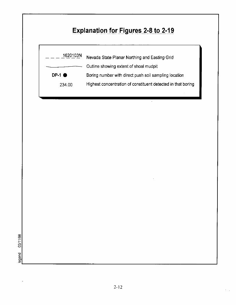
Explanation for Figures 2-8 to 2-19----------- . --- -_.._-------- _ ..._--_.._.... -- --- -------_ .. _-_.._-------------------------------- --------
- - - J620..!93N Nevada State Planar Northing and Easting Grid
Outline showing extent of shoal mudpit
DP-1.
234.00
Boring number with direct push soil sampling location
Highest concentration of constituent detected in that boring
"'CCQ)Cl~
L...- ---J
2-12
5.00
w w~ ~N ~N ~~ N~ ~
I II II I
i D~1~ i____________________1 ~_1J5~[}l_:i~__
SHOAL MUDPIT
DP-S.
P-2e
N~,
II
24Q.00DP-6e :
--------------------1------ ----------[ip:s;-I
D
IIIIIIIIIIIIIIIIII
D~1~ iII
I I
_JL~~[ll_CL3jJ l----------------------------------------------1------------------------------- ~-1J5~[}l-[l~--I I II I II I II I /-,
: : Dr-14eI I II I II I II I II I I
! ! DP-1Je!I I II I II I II I II I I
~ ~ ~
~ ~ ~~i ~1~P-1 mN N ~m m mm m m
en':j'
0S»
3:cQ.
"tJ;:::;:»~S»
-<c:t.(")S» !!-CQ
N (")CI 0 .,......
CD\.;.l ~o NCD I
~ 00-.,S»c:t.0~
3:S»
"00....ttlS»::::!.C3
SHOAL PROJECT/MUOPIT
BARIUM> 1 MG/KG
o 10 20
Scale = 20 feet
40
103.00DP-17.
C"C(Q...D)c.(I):::::I-»:::::ID)
-<::::t(')D)
"T1o cQ'
tv o l:I :::::I ..........
+:0- o (I)(I) N:::::I I_CD...D)::::t0:::::I
s:D)"C0~
OJD)
:::!.l:3
~ /-------------td---------------------------------------------td---------------------------------------------td------------------------------------------
~ ~ ~~ N ~~ ~ ~N ~ ~
~ ~ ~I I
IIIIIIIIIIIIIIIIIIIIIIIIIIIIIII
_JLf2~[l1_5~~ : ----~:f~-}-~-~~9-Q------------------------~----------- JLf2~[l~:i3lJ__I II II II IIIIIIIIII
1 b-r. 00DP-15e
~ ~ ~rl rl rl
_JLf2~[l1_0~--------------------------------------------~ ~-------- JLf2~[l~Cl3lJ__N N N~ ~ ~~ ~ ~
v
SHOAL PROJECT/MUDPIT
BARIUM > 1 MG/KG
o 10 20
Scale = 20 feet
40
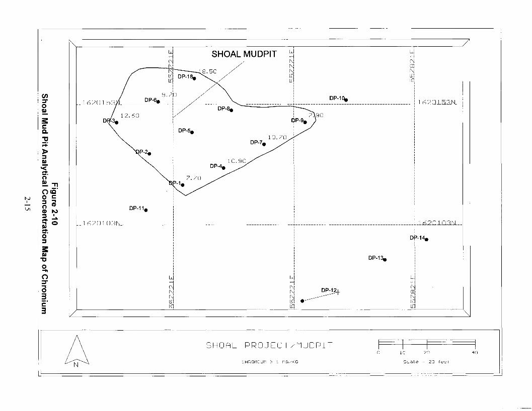
I
i 7.90~P-9.
II
10.70DP-7.
w w~ ~N ~N ~~ ~
~ ~I II II II I
i D~1~ i____________________1 l_lJ5~[lJL:i~__DP-8e
SHOAL MUDPIT
P-2e
DP-11.
f"i~
III
9.7bDP-6. :
--------------------~------IIII
D IIII
i DP-S.IIIIIIIIIIIIII
i 7.70P-1.IIIIIIIIIII II I II I I
_-ltS~[l1_0~~ 1----------------------------------------------1------------------------------ l_lJ5~[lJL[l~__I I II I II I II I b: : Dr -14eI I II I II I II I II I I
i i DP-13e iI I II I II I II I I
~ ~ ~
~ ~ ~~i ~1~P-1 mN N Nm m mm m m
s::r:::::Q.
1J;::+»::JA)
-e!:!:oA) "(')cC'o r:::::::J .,o (I)(I) I\)
;a~
SiJ 0!:!:o::J
s::A)
"o....o::J'"
a3e3
NIVI
SHOAL PROJECT/MUDPIT
CHROMIUM > 1 MG/KG
o 10 20
Scale = 20 feet
40

~ ~ ~M M M
~-ltS~[l~~O~~~~~~~ ~ ~ ~ ~-----~-- -ltS~(l~CL3jj__
N N Nm m mm m m
'~ /~~~~~~~~~~~~~td~~~~~~~~~~~~~~~~~~~~~~~~~~~~~~~~~~~~~~~~~~~~~td~~~~~~~~~~~~~~~~~~~~~~~~~~~~~~~~~~~~~~~~~~~~~td~~~~~~~~~~~~~~~~~~~~~~~~~~~~~~~~~~~~~~~~~~
~ ~ ~~ N ~~ ~ ~N N N~ ~ ~
I II II II II II II II II II II II II II I
: 10.20:i DP-17. iI II II II II II II II II II II II II I
~-ltS~[l~~5~~~~~~~~~~~~~~~~~~~~~~~~~~~~~~~~~~~~~~~~~~~~~~~~~~~~~t]p:f~~!~Q~~~9~~~~~~~~~~~~~~~~~~~~~~~~~~j~~~~~~~~~~~~~~~~~~~~~~~~~-ltS~[l~~3jj~~I II II II II II II II II II I
II
7[40DP-15e
C"CccD1CoCD"::s-»::sD)
-<-n"D)-o:!!occ
N ::s eI
~ CiJ-01 ::s N-I.., ..a.D) ..a.d:0::s3:D)
"C0....0::r..,03c:
1/3
SHOAL PROJECT/MUDPIT
CHROMIUM > 1 MG/KG
o 10 20
Scale = 20 feet
40

.10II
: 2OP-9.
l..cj
~ ~P-1~ .60lfJlf1
SHOAL MUDPIT
46.40DP-5.
2l.P-2e
37.70DP-11.
f\j
~III
17.boDP-6. :
--------------------1------ ----------[ip:a;-I
o
w w~ ~N ~N ~~ ~
~ ~I II II I
: 66.00 :: DP-1Oe :
r7Jd---------------l-------------~-------------- l_lJ5~[lJL:i~__IIIIIIIIIIIIIIIIIIIIIIIIIIIIIIIIIIIIIIIIIIII
_-Lt2~Cll_0~~ 1----------------------- + l_lJ5~[lJLCl~__IL 53.90
D,-14eIII
40.60 :DP-13e i
IIII
uJ
~NlfJlfJ
en::r0I»
:s::£:c."'0;:::;»;:,I»~~(')I»
-"(") _.oc.c
tv ;:, £:I (') .,- ~ ~
-....I ;:, Nr+ I., ...ll.
I» N~0;:,
:s::I»
"C0-G).,0<n<n»"C::rI»
SHOAL PROJECT/MUDPIT
GROSS ALPHA >1 PCI/G
o 10 20
Scale = 20 feet
40
27.30DP-17.
IIIIIIIIIIIIIIIIIIIII
~ ~ ~rl rl rl
_-ltS~[l1_0~--------------------------------------------~ ~-------- -ltS~[l~Cl3lJ__N N N~ ~ ~~ ~ ~
"")----------,--------------,-----------~---------------{/-------------td---------------------------------------------td---------------------------------------------td------------------------------------------
~ ~ ~~ N ~~ ~ ~N ~ ~
~ ~ ~I I II I II I II I II I II I II I II I II I II I II I II I II II II II II II II II II II II II II II II II II II II II I I
I I 35 90 I_-ltS~[l1_5~JU -1-----~:fse----~-----------------------------j-------- -ltS~[l~~lJ__
IIIIIIIIIIIII
2b.40DP-15e
c"rQ~Sl)
c.(I):::::I-»:::::ISl)
-<c:!:oSl)
("')."o _.:::::IrQ
N n r::I (I) ~.....
:::::I(I)
00 -I\,)~ ISl) ....a.c:!:w0:::::I
3:Sl)
"0....G)~
0enen»":::rSl) /
SHOAL PROJECT/MUDPIT
GROSS ALPHA >1 PC1/G
o 10 20
Scale = 20 feet
40

.10II
: 2OP-9.
w w~ ~N ~N ~N ~
~ ~I II II I
: 24~60 :: DP-1Oe :
_7~---------------1---------------------------------- l_lJ5~[)l_~~__
SHOAL MUDPIT
1"'1~
IIII
21.PODP-6e :
--------------------~------ -----------------
i DP-8eI
D II
: 40.10: DP-5.II
22.30:P-2e :
IIIIIII
: 23.20P-1.IIIII
27.40 :DP-11. i
III I
_-L~~[l1_0~~ ~----------------------- ~------------------------------ ~-lJ5~[)l-[l~--I I II I I: : b 37.70: : Dr-14eI I II I II I I
: i 57.90 i
: : DP-1Je:I I II I II I II I II I I
~ ~ ~
~ 8 ~P-1 ~N N .20 Nm m mm m m
en::T0A)
3i:cQ.
"'tJ;::;:»;jA)
-<!:!:(")A)
."Oee'
N o CI ;j ""'I- (") CD
\D CD N;j Ir+ ~""'I ~A)!:!:0;j
3i:A)
't'0-G)""'I0tiltil
OJCDlit
SHOAL PROJECT/MUDPIT
GROSS BETA> 1 PCI/G
o 10 20
Scale = 20 feet
40
C'Cec..,S»C.(6'::::sr+
»::::sS»
-<C';(")S»
0'"o -,::::sec
N (") ~I
N CD CD0 ::::s N
r+,.., -a.
~c.n0::::s
s::S»'C0....Q..,0tiltil
OJCDliT
~ /-------------td---------------------------------------------td---------------------------------------------td------------------------------------------
~ ~ ~~ N ~~ ~ ~~ N N~ ~ ~
I II II II II II II II II II II II II II I
: 25.80:i DP-17. iI II II II II II II II II II II II II I
_~~~[l~_5~~---------------------------------------------~-----~:f6i-?-g~-~9--------------------------~-------- ~~~[l~~3~__I I II I II I II I II I II I II I II I II I II I II I II I I
i 2~.30i DP-15eIIIIIIIIIIIIIIIIIIIII
~ ~ ~M M M
_~~~[l~_O~--------------------------------------------~ ~-------- -l~~[l~Cl3~__
N N Nm m mm m m/
SHOAL PROJECT/MUOPIT
GROSS BETA> 1 PCI/G
o 10 20
Scale = 20 feet
40
II
: 0.18OP-9.
w w~ ~~ ~~ ~~ ~
~ ~I II I
: 0.25 :: D~1~ :
~ l l_lJ5~[l~:i~__
SHOAL MUDPIT
0.39DP-S.
~
~II
0.2bDP-6e :
-------- 4 _
DP-8e
0.27P-2e
IIIII
0.38 :DP-11. i
II II I
_JLf2~CL1_0~jJ l----------------------- - - - - - - - - - - - - - - - - - - - - - - - l - - - - - - - - - - - - - - - - - - - - - - - - - - - - - - +_lJ5~[l~CL~__I II I
: ;., 0.24: Dr-14eI II II I
: 0.20 :i D~1~!I II II II I
~ ~ ~...--j ...--j ?P-1 ...--jN ~ ~N N .25 N~ ~ ~m m m
en~
0A)
3:c::C.
""C;::;»:;,A)
-<ct.(")A)
"T1n _.OCC
N :;, ~IN (") C'D...... C'D N:;, I.... ...a.
DJ enct.0:;,
3:A)
"'C0....oC'Denc3I
...a.to)......
SHOAL PROJECT/MUDPIT
CESIUMI37>0.10 PCI/G
o 10 20
Scale = 20 feet
40

"")--~~~-,----~-~-~--~-------,-~-------~------,-----~-~-------(/
0.39DP-17.
C"Ccc.,D)c.CD
,::::l-»::::lD)
-<!:!'.(')D)
0"Tlo _.::::lcc
N (') c::I CD .,
N ::::l CDN _I\)., ID) ...a.ct. .....0::::l
s::D)"C0-0CDenc::3I
...a.W.....
1/
-------------td---------------------------------------------td---------------------------------------------td------------------------------------------~ ~ ~~ N ~~ ~ ~N N N~ ~ ~
I I II I II I I
I II II II II II II II II I
IIIIIIIIIIIIIIIIIII
: 0 23 :_-Lt2~[l1_5~~---------------------------------------------: ----rnP:f6i---~------------------------------i----------- -Lt2~[l~~3lJ__
I I II I II I II I II I II I II I II I II I II I II I ,I I II , I
: Ol24 :D~1~ ]
IIII
I
~ ~ ~rl rl rl
_-Lt2~[l1_0~--------------------------------------------~ ~-------- -Lt2~[l~CL3lJ__~ ~ ~~ ~ ~~ ~ ~
SHOAL PROJECT/MUDPIT
CESIUM137>O.10 PCI/G
o 10 20
Scale = 20 feet
40

.00
w w~ ~N ~N ~~ N~ ~
I II II I
1 D~1~ 1~~ l l_lJ5~[lJL:i~__
IIIIIIIIIIIIIIIIIIIIIIIIII
DP-8e
SHOAL MUDPIT
------------------~.::...::._---~-
DP-11.
~
~IIII
40.pODP-6e :
---~----------------~------IIII
D II
: 180.001 DP-5.II
25.001P-2e 1
IIIIIII
: 25.00P-1.IIIIIIIIIIIII
_JLtS~Cll_0~jJ l----------------------- + l_lJ5~[lJLCl~__I I II I II I II I /-,
: : D,-14eI I II I II I II I II I I
i i DP-1Je iI I II I II I II I II I I
W W W
~ N7P-1 ~
~ ~ N~ ~ ~~ ~ ~
en:::ro~
NI
NW
SHOAL PROJECT/MUDPIT
TPH DIESEL> 5 MG/KG
o 10 20
Scale = 20 feet
40

.00II
: 2OP-9.
w w~ ~N ~N ~~ N~ ~
I II II II I
i D~1~ i~~ l l_lJ5~[lJL:i~__
IIIIIIIIII
SHOAL MUDPIT
900.00DP-5.
180.00-1.
DP-11.
1"'1~
III
sa.coDP-6e :
--------------------1------ ----------D-p~a;
I
IIIIIIIIIIIII
I I II I I
_JL£2~[l1_0~jj ~----------------------- ~------------------------------ l_lJ5~[lJL[l~__I I II I II I II I b: : Dr -14eI I II I II I II I II I I
i i DP-13e !I I II I II I II I I
~ ~ ~;J ~ 7P-1 ~~ ~ ~N N Nm m mm ~ ~
en::r0D)
3:I:C."tI;::;:»;jD)
-<!:!':(')D) "T1- _.n CC
tv o I:I
;j atv.,J:;. (')
NCD I;j ...a.C:tOD)!:!':0;j
3:D)'t'0-:ED)0-CD
0
SHOAL PROJECT/MUDPIT
WASTE OIL> 1 MG/kG
o 10 20
Scale = 20 feet
40

Hole NO.:DP-1
Surface Elevation:5231.52Depth Depth Strata Rock/Soil Lith(feet) meters Unit
Eastin :557724 90Description
2
0.5
3
1.0
4
ORILLINGMATERIALS
SOILDECOM/GRANITE
Drilling materials. Very light gray, powdery, dusty, very fine grained, dry, unconsolidated, becoming coarser
after 1.0 ft depth.
Weathered granite. Between 2 and 3 ft, getting a small amount of a black, smeary substance on the outside of
the push rods. No reading on the PID, substance not seen in the soil.
Pushed once from 0 to 4 ft. and twice from 0 to 3.5 ft. before refusal. Depth to granite is between 3.5 and 4.0 ft.
Logged.By: IT Corp.lAM Welcher
Drilling Co.: Gregg Drilling Co.
Drillin Method: Direct Push
Figure 2-20Soil Boring Log for DP-1
2-25
IT CORPORATIONProject Shoal
Proiect No. 764044.03.08.00.00

Hole NO.:DP-2
Surface Elevation:5231.94Depth Depth Strata Rock/Soil Lith(feet) meters Unit
Eastin :557711.20
Description
0.5
0.2
1.0
DRILLINGMATERIALS
"soiL'SILTY-SANDY
Drilling materials. Very light gray, powdery, dry, unconsolidated, becoming light gray to light brownish gray, silty
at 0.5 ft.
Light gray to light brownish gray, silty soil, with granite gravel at 1 ft. Could not push deeper than 1 ft Required
14 pushes to a depth of 1 ft to collect adequate sample volume.
Direct Push boring had refusal at 1.0 ft, could not push into granite.
Logged By: IT Corp.lAM Welcher
Drilling 'ce. Gregg Drilling Co.
Drillin Method: Direct Push
Figure 2-21Soil Boring Log for DP-2
2-26
Project ShoalProiect No. 764044.03.08.00.00
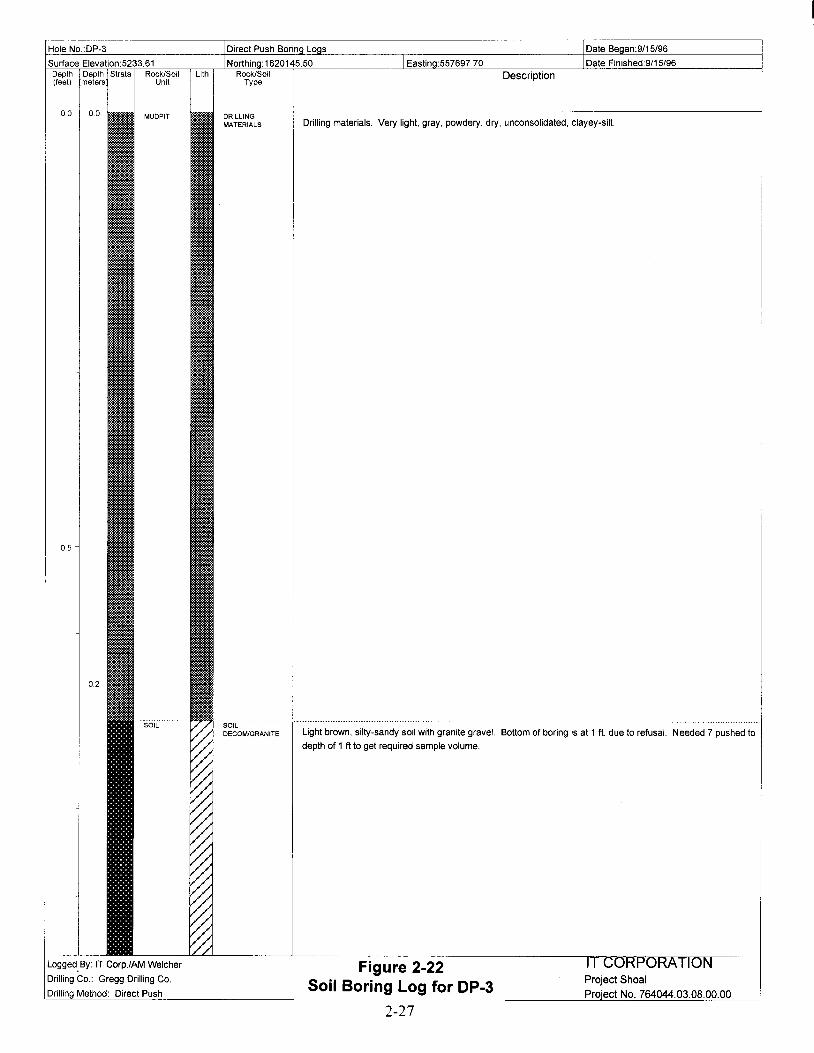
Hole No.:DP-3
Surface Elevation:5233.61Depth Depth Strata Rock/Soil Lith(feet) meters Unit
Eastin :557697.70
Description
-----""----"---'-----------'-_._----------------
Drilling materials. Very light, gray, powdery, dry, unconsolidated, clayey-silt
Project Shoal
Proiect No. 764044.03.08.00.00
Figure 2-22Soil Boring Log for DP-3
2-27
Light brown, silty-sandy soil with granite gravel. Bottom of boring is at 1 ft. due to refusal. Needed 7 pushed to
depth of 1 ft to get required sample volume.
DRILLINGMATERIALS
soilDECOM/GRANITE
0.2
0.5
Logged. By: IT Corp.lAM Welcher
Drilling Co.: Gregg Drilling Co.
Drillin Method: Direct Push

Hole No.:DP-4
Surface Elevation:5231.16Depth Depth Strata Rock/Soil Lith(feet) meters Unit
Eastin :557741.90Description
0.5
0.2
1.0
0.4
1.5
0.62.0
2.5
0.8
3.0
1.0
3.5
1.2
DRILliNGMATERIALS
·-sOiL.·SILTV-SANDY
SOILOECOM/GRANITE
Drilling materials. Very light gray, powdery, dusty, very fine grained, dry, unconsolidated.
From 1.5 to 2: Silty light gray to light brown, dry soil, with some roots. After 2 ft becoming a grayish-brown, and
coarser soil.
Weathered granite with a light brown soil matrix. Bottom of boring at 4.0 ft. due to refusal.
Logged.By: IT Corp.lAM Welcher
Drilling Co.: Gregg Drilling Co.
Drillin Method: Direct Push
Figure 2-23Soil Boring log for DP-4
2-28
IT CORPORATIONProject ShoalProiect No. 764044.03.08.00.00

Hole No.:DP-5
Surface Elevation:5231.17Depth Depth Strata Rock/Soil Lith(feet) meters Unit
Eastin :557728.80Description
0.5
0.2
1.0
04
1.5
0.62.0
2.5
0.8
Loggeq By: IT Corp.lAM Welcher
Drilling Co.: Gregg Drilling Co.
Drillin Method: Direct Push
DRILLINGMATERIALS
soilSILTY·SANDY
·soiC·DECOM/GRANITE
Drilling materials. Light-gray, fine grained, powdery, very dry, unconsolidated. At 0.5 ft, drilling materials
starting to become moist, are darker gray, coarser, and more consolidated.
Between the depths of 1.5 to 2.0 ft, there is a color change between borings in the 2x2 ft area. From moderate
gray, fine grained, moist, with some hornbiende, to orangeish-brown, fine grained, consolidated, to
purplish-reddish brown, platey. Also found an angular gravel sized piece of rhyolite in this interval.
Moderate brown, silty soil.
Weathered granite with a reddish-brown soil matrix. Penetrated to 3 ft before refusal.
Project Shoal
ProiectNo. 764044.03.08.00.00
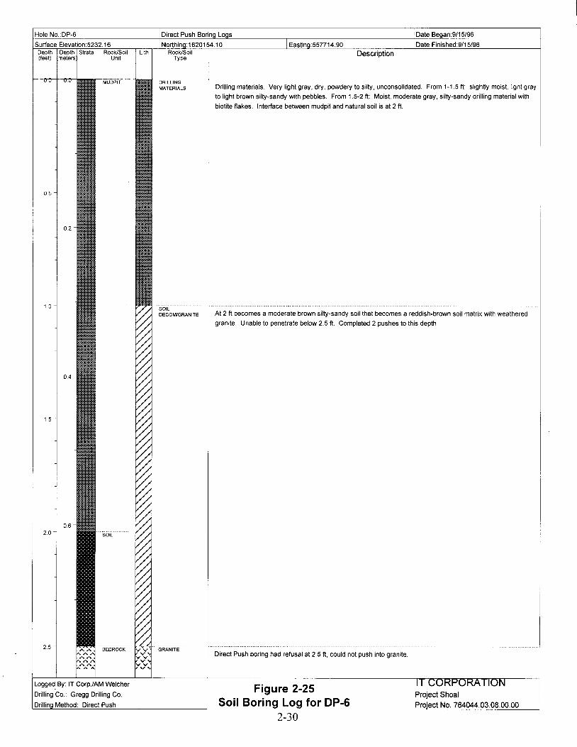
Hole NO.:DP-6
Surface Elevation:5232.16Depth Depth Strata Rock/Soil Lith(feet) meters Unit
Eastin :557714.90
Description
0.5
0.2
1.0
0.4
1.5
0.62.0
2.5
DRILLINGMATERIALS
'soilDECOM/GRANITE
Drilling materials. Very light gray, dry, powdery to silty, unconsolidated. From 1-1.5 ft: slightly moist, light gray
to light brown silty-sandy with pebbles. From 1.5-2 ft: Moist, moderate gray, silty-sandy drilling material with
biotite flakes. Interface between mudpit and natural soil is at 2 ft.
At 2 ft becomes a moderate brown silty-sandy soil that becomes a reddish-brown soil matrix with weathered
granite. Unable to penetrate below 2.5 ft. Completed 2 pushes to this depth.
Direct Push boring had refusal at2.5 ft, could not push into granite.
Project ShoalProiectNo. 764044.03.08.00.00
Figure 2-25Soil Boring Log for DP-6
2-30
Logged,By: IT Corp.lAM Welcher
Drilling Co.: Gregg Drilling Co.
Drillin Method: Direct Push
r---~--'----L------'---~'-------L----- ·-----------------TT~~::IT"i7"'\l:YK_rr7"\li;_r_--__l
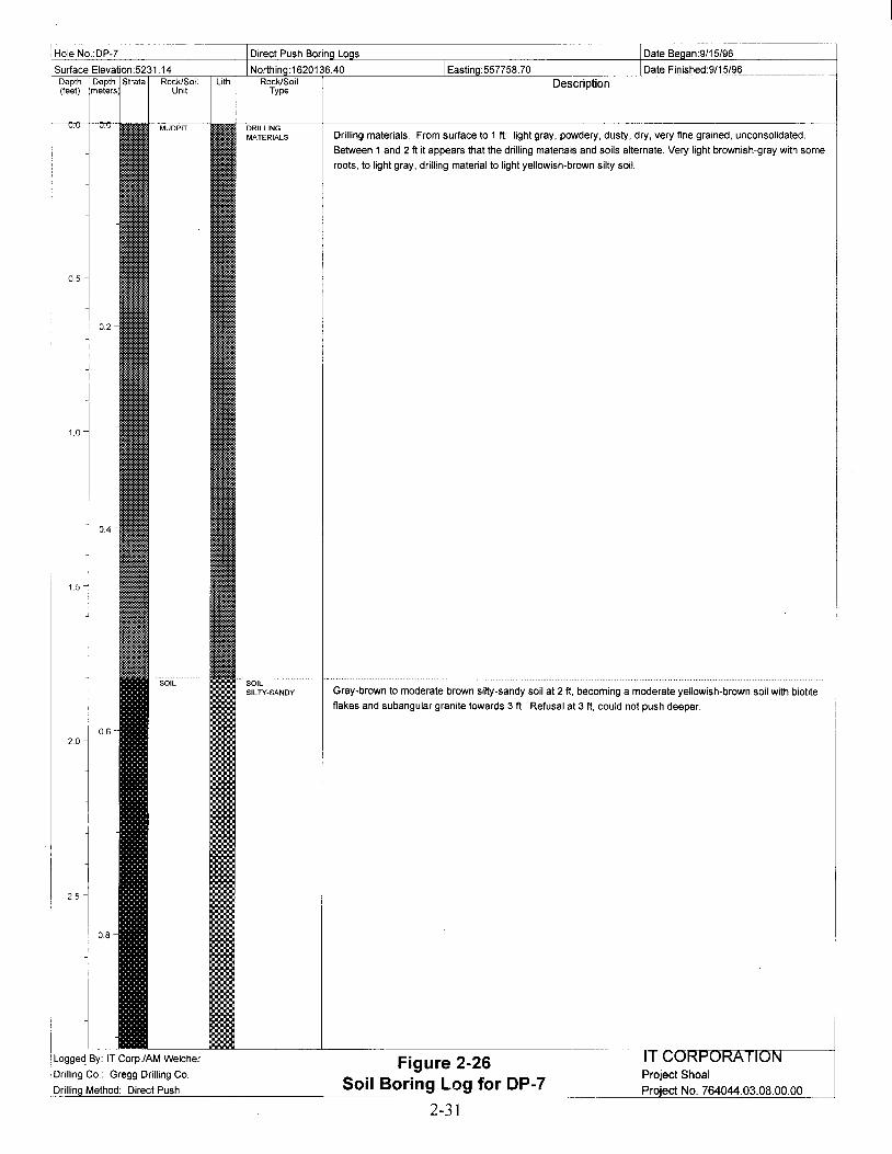
Hole NO.:DP-7
Surface Elevation:5231.14Depth Depth Strata Rock/Soil Lith(feet) meters Unit
Eastin :557758.70
Description
0.5
0.2
1.0
0.4
1.5
0.62.0
2.5
0.8
Loggeq By: IT Corp.lAM Welcher
Drilling Co.: Gregg Drilling Co.
Drillin Method: Direct Push
DRILLINGMATERIALS
SOILSILTY-SANDY
Drilling materials. From surface to 1 ft: light gray, powdery, dusty, dry, very fine grained, unconsolidated.
Between 1 and 2 ft it appears that the drilling materials and soils alternate. Very light brownish-gray with some
roots, to light gray, drilling material to light yellowish-brown silty soil.
Gray-brown to moderate brown silty-sandy soil at 2 ft, becoming a moderate yellowish-brown soil with biotite
flakes and subangular granite towards 3 ft. Refusal at 3 ft, could not push deeper.
Project ShoalProiect No. 764044.03.08.00.00

Hole NO.:DP-8
Surface Elevation:5230.98Depth Depth Strata Rock/Soil Lith(feet) meters Unit
Eastin :557745.20
Description
0.5
0.2
1.0
0.4
1.5
0.6
ORILLINGMATERIALS Drilling materials. Light gray to white, powdery, dusty, very dry, some biotite flakes at 1 ft. Below 1 ft becoming
more consolidated, and darker gray in sample sleeve.
Very thin layer of the very fine grained, light brown soil. Can not push any further than 2 ft. The mud pit is
essentially sitting on the granitic bedrock at this location. Direct Push boring had refusal at 2.0 ft, could not push
i ni
Logged. By: IT Corp.lAM Welcher
Drilling Co.: Gregg Drilling Co.
Drillin Method: Direct Push
Figure 2-27Soil Boring Log for DP-8
2-32
IT CORPORATIONProject Shoal
ProiectNo. 764044.03.08.00.00

Hole NO.:DP-9
Surface Elevation:5231.80Depth Depth Strata Rock/Soil(feet) meters Unit
LithEastin :557775.70
Description
0.5
0.4
0.2
Drilling mud layer I
light-brownish gray with some organics, to light yellowish-brown to moderate yellowish-brown, silty soil, dry,
becoming coarser and darker with depth.
Surface at DP-9 is the light gray drilling material. light gray, fine grained, powdery, very dry.
is very thin here.
The bottom of the boring is at 4 ft. as this was a shallow sample and there was no refusal. The interface
between the decomposing granite and the granite is unknown and the interface is interpreted.
!
light brown, silty sand with angular granitic pebbles and weathered granite. Bottom of boring was at 4 ft, as this Iwas a shallow sample. Depth to interface of decomposing granite and granite is unknown, and the interface is !
The bottom of the boring is at 4 ft. as this was a shallow sample and there was no refusal. The interface
between the decomposing granite and the granite is unknown and the interface is interpreted.
SOILSILTV·SANDY
DRILLINGMATERIALS
SOIl.DECOM/GRANITE
0.8
0.6
1.0
1.2
1.5
2.5
2.0
3.5
4.0
4.5
1.0
3.0
1.4
Logged By: IT Corp.lAM welcher
Drilling Co.: Gregg Drilling Co.
Drillin Method: Direct Push
IT CORPORATIONProject ShoalProject No. 764044.03.08.00.00
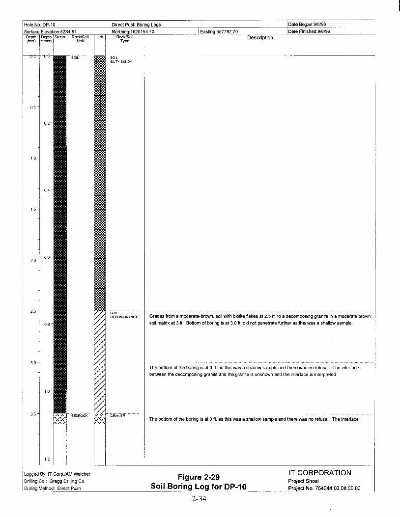
Hole NO.:DP-10
Surface Elevation:5234.51Depth Depth Strata Rock/Soil Lith(feet) meters Unit
Eastin :557792.70Description
0.5
0.2
1.0
0.4
1.5
0.62.0
2.5
0.8
3.0
1.0
3.5
1.2
Logge~ By: IT Corp./AM Welcher
Drilling Co.: Gregg Drilling Co.
Drillin Method: Direct Push
SOILSILTY-SANOY
sole"DECOM/GRANITE Grades from a moderate-brown, soil with biotite flakes at 2.5 ft. to a decomposing granite in a moderate brown
soil matrix at 3 ft. Bottom of boring is at 3.0 ft, did not penetrate further as this was a shallow sample.
The bottom of the boring is at 3 ft. as this was a shallow sample and there was no refusal. The interface
between the decomposing granite and the granite is unknown and the interface is interpreted.
The bottom of the boring is at 3 ft. as this was a shallow sample and there was no refusal. The interface
IT CORPORATIONProject Shoal
Prolect No. 764044.03.08.00.00

Hole No.:DP-11
Surface Elevation:5236.85Depth Depth Strata Rock/Soil Lith(feet) meters Unit
Eastin :55770970
Description
0.5
0.2
10
0.4
1.5
0.62.0
2.5
0.8
3.0
1.0
3.5
1.2
SOILSILTY-SANOY
·-soiC··DECOM/GRANITE
DP-11 was taken from outside the mudpit on an embankment in the surface soil. Grading from very fine
grained, light-brown to medium brown soil.
At 2 ft there is weathered granite in a medium, reddish-brown soil matrix. Bottom of boring is at 3.0, since this
was a shallow sample.
The bottom of the boring is at 3 ft. as this was a shallow sample and there was no refusal. The interface
between the decomposing granite and the granite is unknown and the interface is interpreted.
The bottom of the boring is at 3 ft. as this was a shallow sample and there was no refusal. The interface
between the decomposing granite and the granite is unknown and the interface is interpreted.
Logged. By: IT Corp.lAM Welcher
Drilling Co.: Gregg Drilling Co.
Drillin Method: Direct Push
Figure 2-30Soil Boring Log for DP-11
2-35
IT CORPORATIONProject Shoal
Proiect No. 764044.03.08.00.00
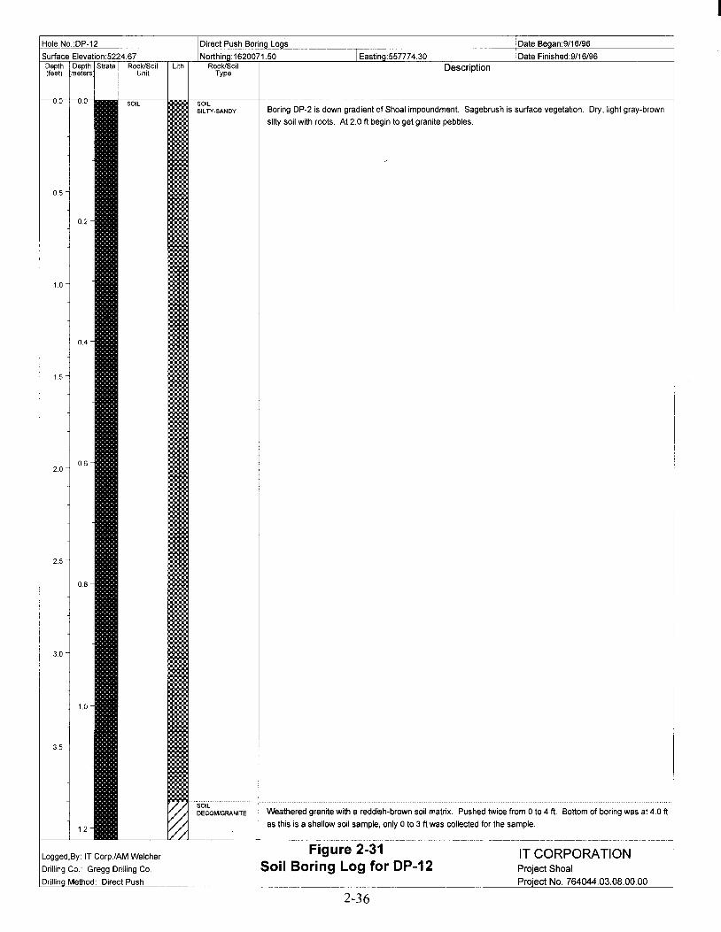
Hole NO.:DP-12
Surface Elevation:5224.67Depth Depth Strata Rock/Soil Lith(feet) meters Unit
Eastin :557774.30Description
I
05
0.2
1.0
0.4
1.5
0.62.0
2.5
0.8
3.0
1.0
3.5
1.2
SOILSILTY-SANDY
SOILDECOM/GRANITE
Boring DP-2 is down gradient of Shoal impoundment. Sagebrush is surface vegetation. Dry, light gray-brown
silty soil with roots. At 2.0 ft begin to get granite pebbles.
Weathered granite with a reddish-brown soil matrix. Pushed twice from 0 to 4 ft. Bottom of boring was at 4.0 ft
as this is a shallow soil sample, only 0 to 3 ft was collected for the sample.
--~----------_._-------- ------- -----------------1
Logged.By: IT Corp.lAM Welcher
Drilling Co. Gregg Drilling Co.
Drillin Method: Direct Push
Figure 2-31Soil Boring Log for DP-12
2-36
IT CORPORATIONProject ShoalProiect No. 764044.03.08.00.00

Hole NO.:DP-13
Surface Elevation:5224.16Depth Depth Strata Rock/Soil Lith(feet) meters Unit
Eastin :557808.60
Description
0.5
0.2
1.0
0.4
1.5
0.62.0
2.5
0.8
SOILSILTY-SANDY
soilDECOM/GRANITE
DP-13 is down gradient from the Shoallmpoundmenl. Light yellowish-brown, silty to sandy soil, dry, becoming
more coarse and gravelly towards 2.7 ft.
Weathered granite with a light brown soil matrix. Gregg drilling pushed twice from 0 to 3 ft, could not push
deeper than 3 ft due to refusal.
Loggeq By: IT Corp.lAM Welcher
Drilling Co.. Gregg Drilling Co.
Drillin Method: Direct Push
Figure 2-32Soil Boring Log for DP-13
2-37
IT CORPORATIONProject ShoalProiect No. 764044.03.08.00.00
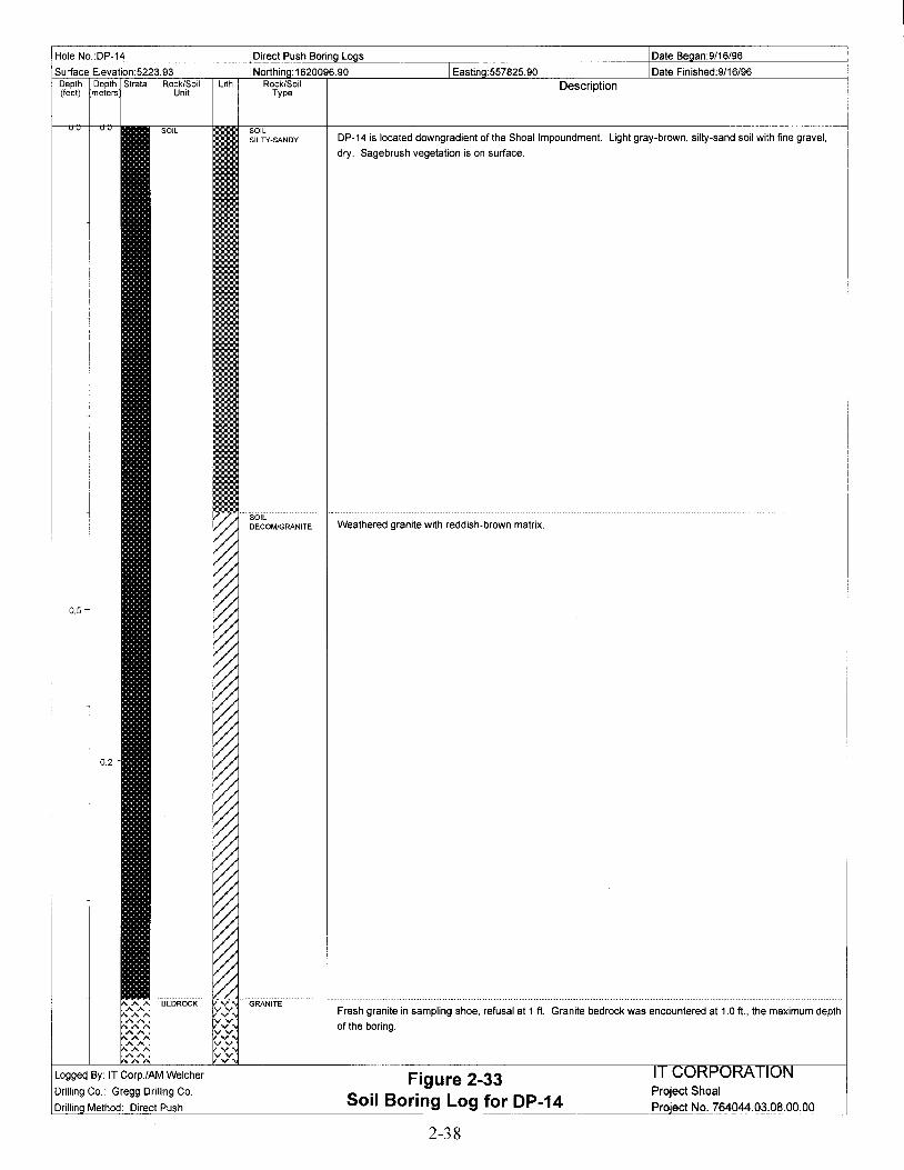
Hole NO.:DP-14
Surface Elevation:5223.93Depth Depth Strata Rock/Soil Lith(feet) meters Unit
Eastin :557825.90
Description
0.5
0.2
Loggeq By: IT Corp.lAM Welcher
Drilling Co.: Gregg Drilling Co.
Drillin Method: Direct Push
SOILSILTY-SANOY
·sOiL.···DECOM/GRANITE
DP-14 is located downgradient of the Shoallmpoundmenl. Light gray-brown, silty-sand soil with fine gravel,
dry. Sagebrush vegetation is on surface.
Weathered granite with reddish-brown matrix.
Fresh granite in sampling shoe, refusal at 1 ft. Granite bedrock was encountered at 1.0 ft., the maximum depth
of the boring.
Project Shoal
Proiect No. 764044.03.08.00.00
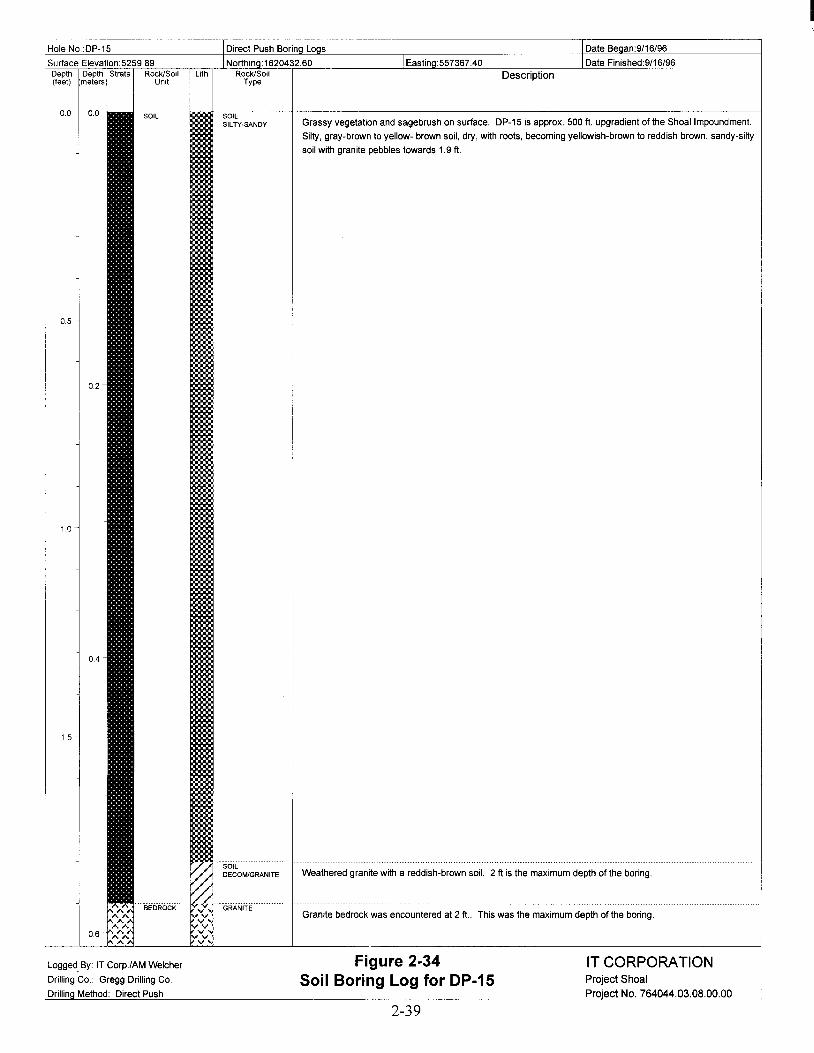
IHole NO.:DP-15
Surface Elevalion:5259.89Depth Depth Strata Rock/Soil Lith(feet) meters Unit
Eastin :557367.40
Description
Granite bedrock was encountered at 2 ft.. This was the maximum depth of the boring.
Weathered granite with a reddish-brown soil. 2 ft is the maximum depth of the boring.
Grassy vegetation and sagebrush on surface. DP-15 is approx. 500 ft. upgradient of the Shoal Impoundment.
Silty, gray-brown to yellow- brown soil, dry, with roots, becoming yellowish-brown to reddish brown, sandy-silty
soil with granite pebbles towards 1.9 ft.
IT CORPORATIONProject Shoal
Proiect No. 764044.03.08.00.00
Figure 2-34Soil Boring Log for DP-15
SOILSILTV·SANDY
. soil.DECOM/GRANITE
1.5
0.2
0.5
0.6
0.4
1.0
Logged. By: IT Corp.lAM Welcher
Drilling Co.: Gregg Drilling Co.
Drillin Method: Direct Push
2-39

Hole No.:DP-16
Surface Elevation:5258.87Depth Depth Strata Rock/Soil Lith(feet) meters Unit
Eastin :557383.50
Description
0.5
0.4
Project ShoalProiect No. 764044.03.08.00.00
Grassy vegetation and sagebrush on surface. DP-16 is approx. 500 ft. upgradientofthe Shoallmpoundmenl.
Silty, gray-brown to yellow- brown soil, dry, with roots, becoming yellowish-brown sandy-silty soil with granite
pebbles towards 3.8 ft.
The interface between the decomposing granite and the granite is unknown and the interface is interpreted.
The boring only penetrated to a depth of 4.0 ft. The interface between the decomposing granite and the granite
is unknown and the interface is interpreted.
Weathered granite with a yellow-brown matrix. Stopped pushing at4 ft. as this was a shallow sample, no
refusal. Gregg Drilling pushed twice from 0 to 4 feet to obtain adequate sample volume.
SOILSILTY-SANDY
"-soilDECOM/GRANITE
0.8
0.6
1.0
1.2
0.2
2.5
2.0
4.0
3.5
1.5
3.0
1.0
Logged, By: IT Corp.lAM Welcher
Drilling co.: Gregg Drilling Co.
Drillin Method: Direct Push

HoleNO.:DP-17
SurfaceElevation:525807Depth Depth Strata Rock/Soil Lith(feet) meters Unit
Eastin :557401.30Description
0.5
1.0
0.2
Grassy vegetation and sagebrushon surface. DP-17 is approx. 500 ft. upgradientof the Shoallmpoundmenl.
Silty,gray-brownto yellow- brownsoil, dry, with roots, becoming yellowish-brown sandy-siltysoil with granite
pebblestowards 3.0 ft.
Weathered granitewith yellow-brownsandy-siltysoil matrix.
The boringwas a shallowsoil sampleand only penetrated to a depth of 4.0 ft. The interfacebetweenthe
decomposing graniteand the granite is unknownand the interfaceis interpreted.
The boringwas a shallow soil sampleand only penetrated to a depthof 4.0 ft. The interfacebetween the
decomposing graniteand the granite is unknown and the interfaceis interpreted.
SOILSILTY·SANDY
'soiL."DECOM/GRANITE
1.0
0.8
0.6
1.2
04
2.5
3.0
3.5
4.0
2.0
4.5
1.5
14
Loggecj By: IT Corp.lAMWelcher
Drilling Co.: Gregg DrillingCo.
Drillin Method: Direct Push
IT CORPORATIONProject ShoalProiect No. 764044.03.08.00.00

Hole NO.:DP-18
Surface Elevation:5231.70Depth Depth Strata Rock/Soil Lith(feet) meters Unit
Eastin :557729.90
Description
--------'""'"'''''--------l........---~--~~~~----------------------_____1
as
0.2
1.0
0.4
1.5
0.6
DRILLINGMATERIALS
'soiL"GILTY-SANDY
DP-18 is in Shoallmpoundmenl. Drilling material. Very light gray to medium gray, powdery, dry,
unconsolidated becoming slightly more consolidated at 1.5 ft.
Moderate brown sandy-silt, with subangular granite pebbles.
Logge~ By: IT Corp.lAM Welcher
Drilling Co.: Gregg Drilling Co.
Drillin Method: Direct Push
Figure 2-37Soil Boring Log for DP-18
2-42
IT CORPORATIONProject ShoalProiectNo. 764044.03.08.00.00

- ------
Table 2-1Summary of Shoal Direct Push Samples
Sample Date Location', Shallow/Deep '! Depth Depth COCa ,CommentsNumber Collected Sample; (meters) • (feet) Number,
__.__.._~_"'~.. . _~____ _ L ... ,---...----...-------L---_- ~ .. I .. ._,_._ ....__.__________________ _ ..__.. _
~§§gQ2g~1 9/15/96, D~_-1~_1__ Sh~lIow '0 - g.6!_ '_~~~~~809 iShallow ~()~posite Sample inside_MU~ Pit _~S00002 9/15/96 --r- __~__1_~ ___l---[)t3.~-- iO.6~~ __--.!..22T 2 - 4 5~~809 I Dee£~()m"posite Sample inside MU9 Pit ~__PSS00003 9/11/96 DP-1! Quality Control (QC)' N/Ab N/A 485538 iField Blank- , ·4-------- , '---~----,. -:~ ------------PSS00004 9/11/96 DP-1 t- QC I N/A ; N/A 485538! EqUipmentRinsatePSS00005 9/15/96-, DP-2 --.~ Shallow-~ i 0-0.31 t~6---1-,-----s:fgeo9 ,Waste Manage~ment Composite -- ~-PSS00006 9/15/96 i DP-2--- Shallow i 0- 0.31! 0-1 • 519809 15Uprrcafe-ofSample PSS00005 u_ --------~--
PSS00007 9/15/96 +__DP-3 _--+-__ Yhallow ~-~~J-519809~ow Compos~te Sample ~n~~deMu~--- _PSS00008 9/15/96 t"- DP-4 +-__~Shallow ' 0 - 0.61; a----~1- 519809, Shallow Composite Sample inside Mud Plt _PSS00009 ----'-- 9/15/96 __ DP-4 '___ _ Deep Q.61 -1.2212 -4 i 519809 ,Deep Composite Sample inside Mud Pit _PSS00010 9/15/96 t~ DP-5 t Shallow 0-0.61 ; 0 __2 i 519809 _Waste Management Composite...LaboratorygC _PSS00011 9/15/96 I __~ DP-5_~ Deep___ 0.61 - .0911..?~ ! ~1980~ __ Deep Composite_Sample inside Mud Pit -c--::--c----:--=-=------
PSS00012 N/A DP-5 N/A i N/A i N/A! N/A Not Collected...Unique number not needed for Lab QCPSS000131- 9/15/96 ~-6_ -- Shallow=-_~~ 0- 0.76TI- 2.51 5~~~09_Shaliow~()rTlPosite Sample insideMllci"pit----- ._.~PSS00014 I 9/15/96 DP-7 ShalloV>'_~ ~ 0.6~_~~Q - 2 i 5~_9809 ,Shallow C~r:!1posite Sample inside_Mud Pit_ ___PSS00015 -r 9/6/96 DP-8 Shallo~_ i 0-0.61__ 0-2 , 4Q4697 !Waste_fIt1~_~agement Composi~~ -j
PSS00016 ! 9/15/96 DP-9 Shallow! 0-0.91 0-3 i 519809 I Shallow Composite Sample inside Mud Pit~ Pssooo:r:7 --! 9/6/96 I DP-10 Shallow --------,~1--O-=-3-'--404697- ShaTIOwComposite Sample adjacent to Mud--PiT~-----
w PSS00018! 9/6/96 I DP-1f---- Shallow 0-0.91--'-0=-3----404697 Shallow Composite SarTlple--acJ}acenttOMUd-Pit-----
PSS0001~~----t- 9/16/96 DP__~=:- ~hallow 0-0.91 1- a-~~_ 519801__§Eallow CompositEl_Sample Downgra~i_e.~~_-froin MUd_~iC=-PSS00020 ' 9/16/96 i DP-13 +- Shallow 0-0.91 0-3, 519801 Shallow Composite Sample Downgradient from Mud PitPSS00021 9/16/96 DP-14 -~ Shallow J 0-0.31 0-5 i 519801- .Shallow Composite Sample Downgradient from MU~PiCPSS00022 9/16/96 DP-15 __ !__ Shallow __' 0-0.61 0:~19801 IShaliow Composite Upgradientfrom Mud PiLLab QC__PSS00023 9/16/96' DP-15 1- Shallow 0-0.61 _O~! 519801 iDuplicat~ofSamplePSSOg022 _~ _PSS00024 . 9/15/96 DP-7 I Deep 0.61 - 0.91! 2=--31519809 Deep Composite Sample inside Mud PitPSS00025 ---'~-- N/A - DP-8 _~__===-_N/A__~-==_+ N/A ~ N7A1--':"~~epcomposite Sample not collected duetoretUSal n _=PSS00026 __ -t·! 9/16/96 _ DP-16__ Shallow I a-0.91_,_Q~J 5198Q.!_u~allow Composite Sample upgradient from Mud P~t _PSS00027 9/16/96 DP-17 -r-. _ Shallow i a-0.91~ ~~_§'!~~Q'1.._~Shaliow Composite Sample upgr~.9ie~!.frol1"J..~_~d Pit _
:~~~~~~~ :;~;: I g::~:=-r-- S~~~W==..O~1- ~:;t~ ;23~-~~ I.::~':~~~()to~op:~~=i~a:~T!I~~~u~~:E=====-· ..•=PSS00030 9/16/96 -L DP-~~_+ QC ~__ ,N/A _ N/A_ i 519805~ld Blan~ ..m~ ••.• _
PSS00031 9/16/96 DP-1;"' __ t_ m QC .! N/A li!~_~a07 ,EquiPrTlE:l!1t Rinsate .. .____ __ ___~Q001 __~{11/96 _ DP-1 .. __ QC 'i. _!'l!..~_f\J~_485538 Trip Bla~~ Quanterra La_b,S!-..l-ou~__ .PST00002 9/6/96 i DP-8-- QC -, N/A N/A I 404697 Trip Blank, Quanterra Lab, St Louis ..--- - ----PST00003 . 9/15/96 t- ~ DP-5 -~-------ac- --, .--~~ N/A -1 519809'Tnp-Blank~QuanterraLab:- StLCllJis--- - - -- -----
I-=--=c=-::-c:-::-:c-----t -------t- ---~----~---------- -- ------ -1- ~ -----------
PST00004 ! 9/16/96 i DP-15 i QC N/A N/A 519807 jTrip Blank, Quanterra Lab, si Louis
'Chain of Custody
"Not Analyzed
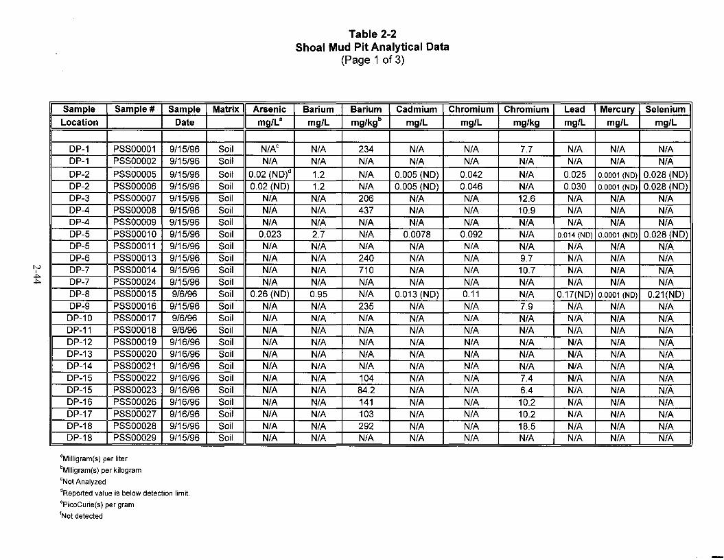
Table 2-2Shoal Mud Pit Analytical Data
(Page 1 of 3)
Sample Sample # Sample Matrix Arsenic Barium Barium Cadmium Chromium Chromium Lead Mercury SeleniumLocation Date mg/La mg/L mg/kgb mg/L mg/L mg/kg mg/L mg/L mg/L
DP-1 PSSOOO01 9/15/96 Soil N/Ac N/A 234 N/A N/A 7.7 N/A N/A N/ADP-1 PSSOOO02 9/15/96 Soil N/A N/A N/A N/A N/A N/A N/A N/A N/A
DP-2 PSSOOO05 9/15/96 Soil 0.02 (ND)d 1.2 N/A 0.005 (ND) 0.042 N/A 0.025 0.0001 (NO) 0.028 (ND)DP-2 PSSOOO06 9/15/96 Soil 0.02 (ND) 1.2 N/A 0.005 (ND) 0.046 N/A 0.030 0.0001 (NO) 0.028 (ND)DP-3 PSSOOO07 9/15/96 Soil N/A N/A 206 N/A N/A 12.6 N/A N/A N/ADP-4 PSSOOO08 9/15/96 Soil N/A N/A 437 N/A N/A 10.9 N/A N/A N/ADP-4 PSSOOO09 9/15/96 Soil N/A N/A N/A N/A N/A N/A N/A N/A N/ADP-5 PSSOO010 9/15/96 Soil 0.023 2.7 N/A 0.0078 0.092 N/A 0.014 (NO) 0.0001 (NO) 0.028 (ND)DP-5 PSSOO011 9/15/96 Soil N/A N/A N/A N/A N/A N/A N/A N/A N/ADP-6 PSSOO013 9/15/96 Soil N/A N/A 240 N/A N/A 9.7 N/A N/A N/ADP-7 PSSOO014 9/15/96 Soil N/A N/A 710 N/A N/A 10.7 N/A N/A N/ADP-7 PSSOO024 9/15/96 Soil N/A N/A N/A N/A N/A N/A N/A N/A N/ADP-8 PSSOO015 9/6/96 Soil 0.26 (ND) 0.95 N/A 0.013 (ND) 0.11 N/A 0.17(ND) 0.0001 (NO) 0.21(ND)DP-9 PSSOO016 9/15/96 Soil N/A N/A 235 N/A N/A 7.9 N/A N/A N/A
DP-10 PSSOO017 9/6/96 Soil N/A N/A N/A N/A N/A N/A N/A N/A N/ADP-11 PSSOO018 9/6/96 Soil N/A N/A N/A N/A N/A N/A N/A N/A N/ADP-12 PSSOO019 9/16/96 Soil N/A N/A N/A N/A N/A N/A N/A N/A N/ADP-13 PSSOO020 9/16/96 Soil N/A N/A N/A N/A N/A N/A N/A N/A N/ADP-14 PSSOO021 9/16/96 Soil N/A N/A N/A N/A N/A N/A N/A N/A N/ADP-15 PSSOO022 9/16/96 Soil N/A N/A 104 N/A N/A 7.4 N/A N/A N/ADP-15 PSSOO023 9/16/96 Soil N/A N/A 84.2 N/A N/A 6.4 N/A N/A N/ADP-16 PSSOO026 9/16/96 Soil N/A N/A 141 N/A N/A 10.2 N/A N/A N/ADP-17 PSSOO027 9/16/96 Soil N/A N/A 103 N/A N/A 10.2 N/A N/A N/ADP-18 PSSOO028 9/15/96 Soil N/A N/A 292 N/A N/A 18.5 N/A N/A N/ADP-18 PSSOO029 9/15/96 Soil N/A N/A N/A N/A N/A N/A N/A N/A N/A
aMilligram(s) per liter
bMlligram(s) per kilogram
eNot Analyzed
dReported value is below detection limit.
·PicoCurie(s) per gram
fNot detected

Table 2-2Shoal Mud Pit Analytical Data
(Page 2 of 3)
Sample Sample # Sample Matrix Silver Gross Alpha Gross Beta Bismuth-214 Cesium-137 Lead-212 Lead-214 Potassium-40
Location Date mg/L pCi/ge pCi/g pCi/g pCi/g pCi/g pCi/g pCi/g
OP-1 PSSOOO01 9/15/96 Soil N/A 20.1 18.9 NOt 0.21 (NO) 0.88 1 25.3OP-1 PSSOOO02 9/15/96 Soil N/A 32.3 23.2 NO 0.19 (NO) 1.2 0.68 24.5
OP-2 PSSOOO05 9/15/96 Soil 0.01 (NO) 10.6 22.3 NO 0.27 (NO) 0.96 1.22 18.5OP-2 PSSOOO06 9/15/96 Soil 0.01 (NO) 21.0 20.8 NO 0.23 (NO) 0.78 0.92 23.2OP-3 PSSOOO07 9/15/96 Soil N/A 10.2 20.5 NO 0.25 (NO) 1.23 0.8 26.8OP-4 PSSOOO08 9/15/96 Soil N/A 23.8 20.7 NO 0.35 (NO) 1.23 0.99 16.4OP-4 PSSOOO09 9/15/96 Soil N/A 27.4 27.3 NO 0.22 (NO) 1.48 1.21 25.1OP-5 PSSOO010 9/15/96 Soil 0.01 (NO) 27.7 18.5 NO 0.22 (NO) 1.01 1.31 15.5OP-5 PSSOO011 9/15/96 Soil N/A 46.4 40.1 1.14 0.39 (NO) 1.86 1.06 16.9OP-6 PSSOO013 9/15/96 Soil N/A 17.0 21.0 NO 0.25 (NO) 1.11 0.83 23.8OP-7 PSSOO014 9/15/96 Soil N/A 30.7 24.0 0.67 0.24 (NO) 0.94 0.85 24.7OP-7 PSSOO024 9/15/96 Soil N/A 35.0 25.3 0.99 0.21 (NO) 1.43 0.99 23.7OP-8 PSSOO015 9/6/96 Soil 0.016 (NO) 33.7 20.7 NO 0.24 (NO) 0.98 NO 21.8OP-9 PSSOO016 9/15/96 Soil N/A 28.1 25.1 NO 0.18 (NO) 1.41 1.09 24.8
OP-10 PSSOO017 9/6/96 Soil N/A 66.0 24.6 0.68 0.25 (NO) 0.5 0.87 27.2OP-11 PSSOO018 9/6/96 Soil N/A 37.7 27.4 NO 0.38 (NO) 2.2 NO 22.1OP-12 PSSOO019 9/16/96 Soil N/A 19.6 24.2 NO 0.25 (NO) 1.12 1.03 24.8OP-13 PSSOO020 9/16/96 Soil N/A 40.6 57.9 1.26 0.20 (NO) 1.34 1.12 27.7OP-14 PSSOO021 9/16/96 Soil N/A 53.9 37.7 1.33 0.24 (NO) 2.04 1.11 20.7OP-15 PSSOO022 9/16/96 Soil N/A 23.9 27.1 1.03 0.24 (NO) 1.01 0.95 23.2OP-15 PSSOO023 9/16/96 Soil N/A 25.4 27.3 1.36 0.23 (NO) 0.85 0.93 25.4OP-16 PSSOO026 9/16/96 Soil N/A 35.9 30.0 0.82 0.23 (NO) 1.04 0.83 21.2OP-17 PSSOO027 9/16/96 Soil N/A 27.3 25.8 NO 0.39 (NO) NO NO 17OP-18 PSSOO028 9/15/96 Soil N/A 15.3 18.5 NO 0.46 (NO) NO 1.75 17.1OP-18 PSSOO029 9/15/96 Soil N/A 56.9 47.1 NO 0.24 (NO) 1.17 0.91 18.7
aMilligram(s) per liter
bMlligram(s) per kilogram
eNot Analyzed
"Reported value is below detection limit.
ePicoCurie(s) per gram
'Not detected

Table 2-2Shoal Mud Pit Analytical Data
(Page 3 of 3)
Sample Sample # Sample Matrix Radium-226 Radium-228 Thallium-208 Thorium-234 Tritium Diesel Waste Oil
Location Date pCi/g pCi/g pCi/g pCi/g pCi/g mg/kg mg/kg
OP-1 PSSOOO01 9/15/96 Soil NO NO NO NO 0.005 25 (NO) 180OP-1 PSSOOO02 9/15/96 Soil 3.11 NO 0.48 NO 0.0008 N/A N/A
OP-2 PSSOOO05 9/15/96 Soil NO NO 0.31 NO 0.006 25 (NO) 130OP-2 PSSOOO06 9/15/96 Soil NO 1.03 0.3 NO 0.005 25 (NO) 140OP-3 PSSOOO07 9/15/96 Soil NO NO 0.72 NO -0.006 25 (NO) 50OP-4 PSSOOO08 9/15/96 Soil NO NO 0.34 NO -0.002 25 (NO) 300OP-4 PSSOOO09 9/15/96 Soil NO NO 0.48 NO 0.005 N/A N/AOP-5 PSSOO010 9/15/96 Soil 5.23 1.41 0.35 NO 0.076 180 900OP-5 PSSOO011 9/15/96 Soil NO NO NO NO 0.01 N/A N/AOP-6 PSSOO013 9/15/96 Soil 3.75 1.53 0.44 NO 0.003 40 93OP-7 PSSOO014 9/15/96 Soil NO NO 0.32 1.94 0.003 25 (NO) 190OP-7 PSSOO024 9/15/96 Soil NO NO 0.48 NO 0.002 N/A N/AOP-8 PSSOO015 9/6/96 Soil NO NO 0.37 NO 0.011 300 (NO) 300 (NO)OP-9 PSSOO016 9/15/96 Soil NO 1.59 0.72 NO -0.002 25 (NO) 25 (NO)
OP-10 PSSOO017 9/6/96 Soil NO NO 0.34 NO -0.004 N/A N/AOP-11 PSSOO018 9/6/96 Soil NO NO NO NO 0.013 N/A N/AOP-12 PSSOO019 9/16/96 Soil 5.78 NO 0.36 NO -0.003 N/A N/AOP-13 PSSOO020 9/16/96 Soil NO 1.76 0.57 NO -0.009 N/A N/AOP-14 PSSOO021 9/16/96 Soil NO NO 0.39 NO -0.005 N/A N/AOP-15 PSSOO022 9/16/96 Soil 2.84 1.23 0.36 NO NO N/A N/AOP-15 PSSOO023 9/16/96 Soil NO NO 0.42 NO NO N/A N/AOP-16 PSSOO026 9/16/96 Soil 3.43 NO 0.31 1.87 NO N/A N/AOP-17 PSSOO027 9/16/96 Soil NO NO 0.74 NO NO N/A N/AOP-18 PSSOO028 9/15/96 Soil NO NO 1.06 NO -0.003 110 890OP-18 PSSOO029 9/15/96 Soil NO NO 0.37 NO 0.005 N/A N/A
aMilligram(s) per liter
bMlligram(s) per kilogram
eNot Analyzed
"Reported value is below detection limit.
ePicoCurie(s) per gram
'Not detected

Table 2-3a and 2-3bShoal Mud Pit Quality Control Sample Data
Table 2-3a
ISample# ISample Date I Matrix IArsenic Barium Cadmium Chromium Lead Mercury Selenium Silver
ug/La ug/L ug/L ug/L ug/L mg/Ld ug/L ug/L
PSSOOO03 9/11/96 Water N/Ab 1.8 N/A 2.3 (NO) N/A N/A N/A N/APSSOOO04 9/11/96 Water 0.002 (NO)c 0.083 0.0005 (NO) 0.0023 (NO) 0.0014 (NO) 0.0001 (NO) 0.0028 (NO) 0.001 (NO)PSSOO030 9/16/96 Water N/A 0.9 N/A 4.4 (NO) N/A N/A N/A N/APSSOO031 9/16/96 Water 20 (NO) 420 5 (NO) 23 (NO) 16 0.0001 (NO) 28 (NO) 10 (NO)
Table 2-3b
I Sample# ISample Date I Matrix IDiesel Waste Oil Tritium Gross Alpha Gross Beta Cesium-137 Potassium-40mg/L mg/L pCi/Le pCi/L pCi/L pCi/L pCi/L
PSSOOO03 9/11/96 Water 0.5 (NO) 0.5 (NO) -3.3 0.15 0.28 2.46 (NO) NOt
PSSOOO04 9/11/96 Water 0.5 (NO) 0.5 (NO) 64.4 0.15 0.16 0.32 (NO) NOPSSOO030 9/16/96 Water 0.5 (NO) 0.5 (NO) -50 0.63 -0.43 7.71 (NO) NOPSSOO031 9/16/96 Water 0.5 (NO) 0.5 (NO) -112 1.81 -0.43 8.05 (NO) NO
Note: Analytical results for volatile organic compounds for trip blank samples PST00001, PST00002, PST00003, and PST00004 were at nondetectable levels.Analytical results for volatile organic compounds and semi-volatile organic compounds for rinsate blanks PSS00004 and PSS00031were at nondetectable levels.
aMicrogram(s) per liter
"Not Analyzed
cReported value is below detection limit
dMilligram(s) per liter
·PicoCuries per liter
fNot detected

This page intentionally left blank
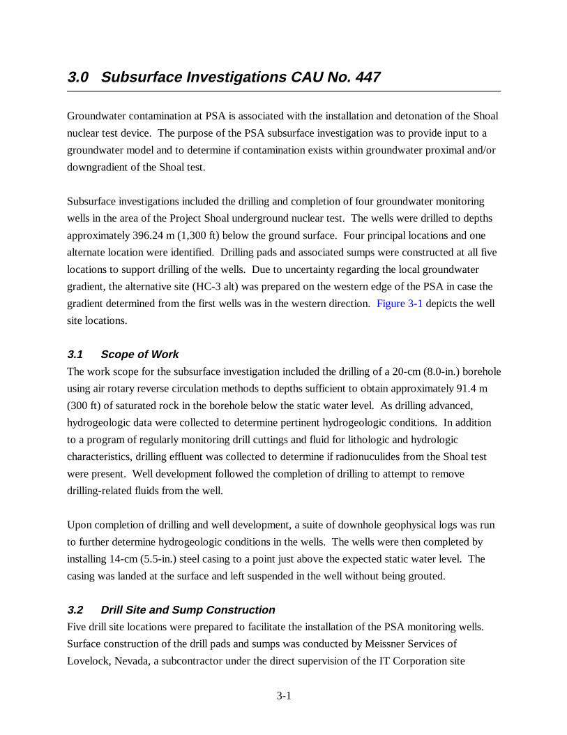
3-1
3.0 Subsurface Investigations CAU No. 447
Groundwater contamination at PSA is associated with the installation and detonation of the Shoal
nuclear test device. The purpose of the PSA subsurface investigation was to provide input to a
groundwater model and to determine if contamination exists within groundwater proximal and/or
downgradient of the Shoal test.
Subsurface investigations included the drilling and completion of four groundwater monitoring
wells in the area of the Project Shoal underground nuclear test. The wells were drilled to depths
approximately 396.24 m (1,300 ft) below the ground surface. Four principal locations and one
alternate location were identified. Drilling pads and associated sumps were constructed at all five
locations to support drilling of the wells. Due to uncertainty regarding the local groundwater
gradient, the alternative site (HC-3 alt) was prepared on the western edge of the PSA in case the
gradient determined from the first wells was in the western direction. Figure 3-1 depicts the well
site locations.
3.1 Scope of WorkThe work scope for the subsurface investigation included the drilling of a 20-cm (8.0-in.) borehole
using air rotary reverse circulation methods to depths sufficient to obtain approximately 91.4 m
(300 ft) of saturated rock in the borehole below the static water level. As drilling advanced,
hydrogeologic data were collected to determine pertinent hydrogeologic conditions. In addition
to a program of regularly monitoring drill cuttings and fluid for lithologic and hydrologic
characteristics, drilling effluent was collected to determine if radionuculides from the Shoal test
were present. Well development followed the completion of drilling to attempt to remove
drilling-related fluids from the well.
Upon completion of drilling and well development, a suite of downhole geophysical logs was run
to further determine hydrogeologic conditions in the wells. The wells were then completed by
installing 14-cm (5.5-in.) steel casing to a point just above the expected static water level. The
casing was landed at the surface and left suspended in the well without being grouted.
3.2 Drill Site and Sump ConstructionFive drill site locations were prepared to facilitate the installation of the PSA monitoring wells.
Surface construction of the drill pads and sumps was conducted by Meissner Services of
Lovelock, Nevada, a subcontractor under the direct supervision of the IT Corporation site

3-2
manager. Installation of liner materials in the excavated storage sumps was completed by
IT Corporation personnel.
The drilling locations consisted of level earthen pads of cut and fill construction, measuring
45.7 m (150 ft) in length and 45.7 m (150 ft) in width. Two sumps were excavated within the pad
area as specified in the Fluid Management Plan (FMP) for the Project Shoal Area Offsites
Subproject (DOE/NV, 1996c). Sump No. 1 was constructed with a surface dimension of
approximately 50 ft x 50 ft and 2:1 sloping walls to a depth of 6.0 ft. Sump No. 2 was
constructed with a surface dimension of 40 ft x 40 ft and 2:1 sloping walls to a depth of 6 ft.
As specified in the FMP (DOE/NV, 1996c), sump liners were installed in each of the excavated
sumps. The sumps were constructed and lined in two configurations. A single 36-mil (.036-in.)
Hypalon liner was installed in one of the sumps to provide for storage of uncontaminated fluids
and cuttings, and two 36-mil (.036-in.) liners separated by 200-mil (.200-in.) geonet were
installed with a leak detection system in the second sump. Liners were all installed on
0.34 kilogram (12-ounce) Geotextile material to prevent puncture from earthen materials within
the excavated sump.
3.3 Summary of Monitoring Well Drilling and Completion OperationsDrilling of monitoring wells at the PSA commenced on September 9, 1996, and was completed on
November 13, 1996. Forty-one days were spent drilling and completing the wells. Operations
were conducted 7 days per week, 24 hours per day for the term of the project. Several short
breaks (2 to 3 days) were taken due to unplanned equipment breakdowns and to give the staff a
break.
The four monitoring wells were drilled in the following order: HC-1, HC-2, HC-4, and HC-3. All
wells were drilled to approximately 396.2 m (1,300 ft) bgs. The total drilled footage for the
project was 1,600.8 m (5,252 ft). Well Site HC-3 was used instead of Alternative 3 because the
results obtained from the installation of Wells HC-1, HC-2, and HC-4 indicated that the
potentiometric surface dipped to the east. All drilling was conducted using air rotary reverse
circulation methods. Wells were completed by installing threaded and coupled 14-cm (5.5-in.)
carbon steel casing to a point just above the static water table. The casing was not cemented in
place to facilitate later removal or repositioning based on modification of scientific objectives or
changes in static water levels within the wells. Well HC-1 was originally drilled and completed to
a depth of 323.1 m (1,060 ft); however, it was later reentered, drilled, and completed to a depth
of 409.35 m (1,343 ft) because of falling water levels within the well.

3-3
The groundwater flow gradient was interpreted based on water levels obtained from the four
wells installed in the subsurface investigation. The flow gradient is apparently in an east-
southeast direction as depicted in Figures 3-2 and 3-3.
Regular monitoring of drilling effluent for tritium and other radionuculides was conducted on all
of the wells during drilling and development. No indications of radiation above background levels
were noted.
Drilling and well completions were conducted by Beylik Drilling of North Highlands, California.
Borehole geophysical logging was conducted by Century Geophysical Corporation of Tulsa,
Oklahoma, and borehole video logs and additional geophysical logging were conducted by the
Desert Research Institute (DRI). Beylik Drilling and Century Geophysical Corporation were both
direct subcontractors to IT. Well drilling, construction, and geophysical logging operations were
directly supervised by IT.

eHC3-Alt= = = = = = -=-.--=-)
"4532
L.EGEND
@ Abandoned well or boring
• Proposed well (approximate location)
- Withdrawn area boundary
--- Topographic contour (Interval =200 feet)
"5365 Point elevation
• - - Unpaved road
SGZ Surface ground zero
- - - Approximate location of groundwater divide
0,6 1,2 Kilometers
SCALE
0.25 0.5 Miles
Source: DOE, 1996
o
ocoCJ)
(0
~o
LOottl
Noo~ L..- .~.__,_ •• .•• _,_~.__~. . ---.,..---....1
Figure 3-1Shoal Well Location Map
3-4
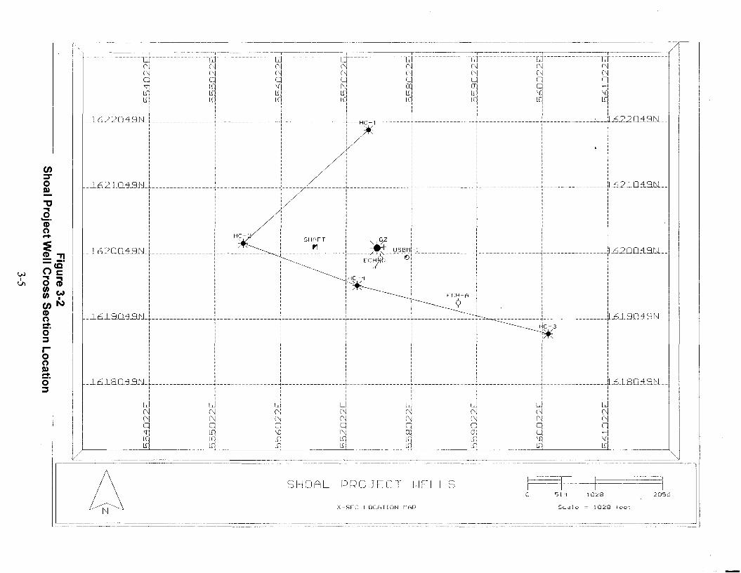
W1VI
en::roI»
""C.,.2.
CD(")-s~"T1neg'., .,o CDtn Wtn I
en NCD(")C':o;j
Io(")I»C':o;j
..=-:-=~~li m - m m--_--l=]~--=------------=----=[J-==-=-=--=--=--==-==iJ----------------l~f ----------------l~F=-=-=-=---: -==--=--== ---d----------------iJ---==--------------N N N N N N N NN N N N N N N Nq q q q q q q q~ ~ ~ ~ ~ ~ q ~
~ ~ ~ ~ ~ ~ ~ ~I I t I I I I II I I I I I I tI I I I I I I I__1622Q1.9N_L 1 -L -L__ -HE-t- L -1- J- .; [ .6220 ± 9.N.--: I : : -, / :::1 I I I I II I I I I It I I I I II I I I t I1 1 I I I II I I I II 1 1 I !1 I IttI 1 I I !J t I I I1 I I I I1 I I t I1 I I I IJ I J I I 1
_JL!S21.Q1.9N_} , J ----/'-----------~-----------------, -----------------t-----------------~------ ~.62-LO:l9.N.--I I I I I I IItt I I I I
I tIl I I II I t r I I II I I I I I II I I I t I II I I I I I II I j I I 1 II I I I I I II I I t I J IJ I I I I I II I H~- 1 tit I
! !, SHAFT!" ¥ t ! 1 [
-JL!S 2QQ1.9N_}--- - - - - -- -- -- - - - -i------~-~----- -T - - - - - - - _'3_ ------+----~~fc"--~-S-~f.1- -----------. ---i-----------------+-----------------r .620O±9.1:.1._I I -c, I I I I I
I '~ I I I II I I t I I II I I I I I t
: : tHC~4 : : : 1I I ,-......;,~ I I I I
: : :~: : : :: : : 'ECH-A l : :I I 1 I A 1 I II I I J 'r': I II I 1 I I I I
_JL6JL9._Cl1.9N_T ~-----------------~------ ~-----------------~-----------------~-- ~------------------~.6-L~O±9.N.--: 1 : 1 : f~C-3 :1 I I I I I'.. / II I I t I II I I I I 1/ -, 1t I I I I I jJ I I r I I 1I I I I I 1 1I I I I I I 1I I I I I I 1I I I I I I It I I I I I II I I I I I II I I I I I II I I J I I I
_JL!S JL8.Q1.3N_L -J J. -L > --1 J. ~ .6.LBO± 9.N.--I J I I I 1 I II I I I tIl II I I I I 1 I II I I lIt I I
~ ~ ~ ~ ~ ~ ~ ~N N N N N N N NN N N N N N N Nq q q q q q q q~ ~ ~ ~ ~ ~ q ~
~ ~ ~ ~ ~ ~ ~ ~, I , I ! ! , ,
Scale = 1028 feet
20561028511oPROJ[CT
X-SEC LOCATION MAP
SHOAL
------ ------------------------l.::---== ~ ~__

5400.00
5350.00
5300.00
5250.00
5200.00
5150.00
5100.00
5050.00
5000.00
4950.00
4900.00
4850.00
4800.00
4750.00
4700.00
4650.00
4600.00
4550.00
4500.00
4450.00
4400.00
4350.00
4300.00
4250.00
4200.00
415000
4100.00
4050.00
4000.00
3950.00- 3900.00
3850.00
-- -3800.00
3750.00-
._-----
_. ------
3018
-----=================
-----._~--_._._-----
SHOAL PROJECT WELLS
2571
11>
rou
.. 305.0 en
~- ) ( ~, --- .;......-....:-_--- ~---~--7
--- -------- --~--
1------ HC-2 --------_.HC-l KG v~
v1---. v "-
.w v~" v HC 4v v~v v r----v "vv v
v v vv v .r.v vv v v
v~v vv V
Ir "V VV V V
~v'<-v v KGv v
v~v v vv v .r:v v
v v v:v>v'<- ~vv v
v
v~ ~vv v vv ,Xvv v
vKGA
~v
1">v";vv
v~v v
KG v10tvv v
v v v r.-v vv~ ~vv
vv r.-v
v~ ~vvvv r.-v vv v
v v v1-'>v:'; ~vv
v
v~ ~vv ~~IS v vVvv vv v
v~,:v~ ~Vv KG vv v v
v v v VVvv v vv v v v
V~ ~Vvv vv v
v v vv v v
,,::':Vv v vv v v
~vVv v
KG v v vv v v v
v v vv>v v v
v v vv'\ \l~Vv
v v\l "
v IvVvv v v~
v - -- --- - - - '" --------- -------------------~v
I-'~':t'( - ---~VV v
v'\ I.-Vv <X - vv -- Iv'":~v v v --v v v - - f.:"Vv~.
v'<- ~VV v ---v -- f.:"Vvf---V~ "VV v
~-
v -- '{".Vv v --v v -- '{".Vv'\v --v --- "
vv'\
vv ---:t. ~VVv
,,:VV
- __r.-VV -_._-----ivVv
--!"> -
'-r~ __._---- --
L. --
]
- 0.0 0
If;oC1
1~?::S
5400.00
535000
530000
525000
520000
5150.00
510000
5050.00
5000.00
4950.00
490000
485000
en 4800.00::::r 4750000D) 4700.00
" 4650.00
0" 460000
:IE 4550.00
G'>" 4500.00., _.D)ce 445000
We:s: 4400.00
I CD ~0\ ::;, 4350.00-W0 I 4300.00W.,
4250.000til 4200.00tilen 4150.00
CD 4100.00(')
4050.00!:!':0 400000::;,
3950.00
3900.00
3850.00
3800.00
3750.00

4-1
4.0 Well HC-1 Summary of Operations
Well HC-1 was initially drilled to a depth of 323.09 m (1,060.0 feet) between
September 26, 1996, and October 2, 1996, and then reentered on October 25, 1996, and
advanced to a depth of 409.35 m (1,343.0 ft). The final completion of the well occurred on
October 28, 1996. A total of 13 days, including both phases, was spent drilling and completing
this well. Figure 4-1 is a summary of the drilling parameters for the well. Note that Figures 4-1
through 4-10 and Tables 4-1 through 4-5, cited in the following text, are located at the end of this
section.
Prior to mobilization, all drilling equipment was decontaminated at the on-site decontamination
pad using a combination of steam cleaning and high pressure washing. Decontaminated
equipment was subjected to a final radiologic screening prior to movement to the drill site.
Initial drilling of Well HC-1 commenced on September 26, 1996. A 30.48-cm (12.0-in.) hole was
drilled to a depth of 31.00 m (101.7 ft). A 21.90-cm (8.625-in.) conductor casing was installed in
the borehole and cemented in place. The main hole of the well was advanced using an 20.3-cm
(8.0-in.) downhole percussion hammer and air rotary reverse circulation drilling techniques to an
initial total depth (TD) of 323.09 m (1,060.0 ft).
The initial depth of Well HC-1 was determined from where water was first encountered during
drilling and then compared to historic water levels from nearby wells. Given this information, it
was decided the well would provide adequate open borehole below the estimated water level for
later scientific investigations to be conducted by DRI.
Due to unstable, sloughing borehole conditions, the well could not be developed/cleaned using
reverse circulation drilling techniques. The drilling configuration was then changed to
conventional direct circulation, and the well was developed. Foam drilling additives were used
initially to establish circulation. The well was then completed by installing 13.97-cm (5.5-in.)
carbon steel casing to a depth of 291.51 m (956.4 ft) and landing the casing in suspension from a
landing plate mounted on the surface casing.

4-2
Water-level monitoring, conducted by DRI and IT after completion of the well, indicated that
water levels within the well were consistently falling with time. These water levels indicated that
the well was not drilled to a depth suitable for scientific study of the saturated portions of the
well.
After approval by the DOE, the 13.97-cm (5.5-in.) intermediate casing was pulled from HC-1,
and the well was reentered with a 20.00-cm (7.875-in.) percussion hammer. The bottom of the
hole was drilled using air rotary reverse circulation drilling techniques and advanced to a depth of
409.35 m (1,343.0 ft). The hole began to slough in at this point, and additional time was spent
working to extract the drill pipe from the hole. After pulling the 20.00-cm (7.875-in.) drilling
assembly from the hole, a depth check was made to determine the TD of the well. It was
determined that the well had sloughed in to a depth of 406.91 m (1,335.0 ft).
Intermediate casing (13.97 cm [5.5 in.]) was then re-installed in the well to 333.70 m (1,094.8 ft)
bgs. After landing the casing, the hole was reentered with a 11.75-cm (4.625-in.) tricone button
bit, again using reverse circulation in an effort to clean the hole out to the total drilled depth of the
well (409.35 m [1,343.0 ft]). The well was circulated and cleaned to the bottom, and the final
depth of the well was 403.80 m (1,324.8 ft). The drilling assembly was then pulled from the
borehole, and the drilling equipment was rigged down for decontamination and mobilization to
HC-2.
4.1 Well HC-1 GeologyWell HC-1 encountered a fractured, coarse-grained biotite granite throughout the drilled interval.
Several, thin, 3- to 6-m (10- to 20-ft) intrusive dikes of Tertiary-aged andesite were noted
between 274.93 and 281.33 m (902.0 and 923.0 ft). The andesite dikes were localized along
steep fault and fracture zones within the granite. These andesite filled fracture/fault zones were
primarily responsible for borehole sloughing and unstable drilling conditions. Descriptions of the
lithologies that were encountered are provided as Figure 4-2.
4.2 Well HC-1 Hydrology Several elements of hydrologic importance were monitored during and after completion of the
well. During drilling, two parameters were consistently compared: the volume of drilling fluid
(water) injected to facilitate drilling and the volume of fluid produced as discharge to the surface.
Figure 4-3 illustrates the relationship between injected drilling fluids and drilling fluid produced at
the surface.

4-3
In addition to volumetric measurements, all drilling fluids injected into the borehole were tagged
with a tracer solution of Lithium Bromide (LiBr). The concentration of LiBr in solution was
monitored on a regular basis to estimate groundwater production within the borehole. Table 4-1
illustrates LiBr concentrations noted in produced fluids.
Water production from the well was minimal; monitoring data and water level recovery data
suggests the well was capable of producing approximately 2.8 to 3.8 liters per minute (L/min)
(0.75 to 1.0 gallons per minute [gpm]). During several instances, the well was capable of
intermittent production on the order of 11.4-18.9 L/min (3.0 to 5.0 gpm). These readings suggest
production from perched water zones along fault or fracture zones. These zones were of limited
impact as their storage capacity was exhausted, and in turn, their contribution to the well
decreased.
Water-level monitoring was conducted during the construction of the well and continued after
completion using transducers set by DRI. Table 4-2 provides water levels obtained for the term
of IT involvement in PSA field work.
4.3 Well HC-1 Geophysical SurveysUpon completion of drilling to the initial TD of 323.09 m (1,060.0 ft) and after well development,
a suite of downhole geophysical surveys was run within the borehole. Upon reentering the well
and deepening the borehole, a second phase of geophysical logging occurred to capture
geophysical data from the deepened interval 323.09 to 409.35 m (1,060.0 to 1,343.0 ft). Due to
the instability of the borehole, it was necessary to install casing across an interval not logged in
the first logging session; in turn, certain intervals of the borehole were not available for logging.
Deviation surveys were also conducted within the borehole and indicated the borehole was
deviated 14.2 degrees from vertical in a west-southwest direction. The deviation of the hole
placed the bottom of the hole 79.68 m (261.4 ft) west-southwest of the collar and resulted in a
true vertical depth of 394.68 m (1,294.87 ft) bgs.
Table 4-3 provides a summary of the geophysical logs run for the well. Figures 4-4 to 4-7
provide a condensed illustration of log traces for HC-1.

4-4
4.4 Well HC-1 Radiologic MonitoringMonitoring of discharge effluent from drilling was conducted as specified in the Project Shoal
Site-Specific Health and Safety Plan (SSHASP) (DOE/NV, 1996b) and the FMP for the Project
Shoal Area Offsite Subproject (DOE/NV, 1996c). Regular radiological monitoring of discharged
drilling effluents, including both fluids and solids, was conducted by Bechtel Nevada radiation control
technicians.
Samples were screened using hand-held instruments at the time of collection. Effluents were further
analyzed for tritium and other radionuculides using on-site laboratory monitoring equipment. Tritium
activities from fluid and swiped samples were recorded using a Packard Liquid Scintillation
instrument. Other radionuculides were analyzed using Canberra gamma spectroscopy instrumentation.
Based on field monitoring, Well HC-1 effluents were found to contain natural background levels of
tritium and all other radionuculides. Figure 4-8 provides a profile of tritium encountered in the well.
4.5 Well HC-1 Well ConstructionWell HC-1 drilling operations commenced on September 26, 1996. A 30.48-cm (12.0-in.) surface
hole was drilled to a depth of 31.00 m (101.7 ft) bgs using a downhole percussion hammer and air
rotary reverse circulation drilling techniques. The 21.91-cm (8.625-in.) surface conductor casing was
then set and cemented in place using Type II neat cement with an additive of 2 percent calcium
chloride. An 20.32-cm (8.0-in.) hole was advanced below the surface conductor casing using
20.32 cm (8.0-in.) downhole percussion hammer and reverse circulation to a final depth of 409.34 m
(1,343.0 ft) bgs. Intermediate casing consisting of 13.97-cm (5.5-in.) carbon steel was installed in the
well upon completion of main hole drilling. Casing was set to a depth of 333.45 m (1,094.0 ft) and
suspended at that point from a landing clamp secured to the surface conductor casing. No centralizers
or cementing baskets were placed on the 13.97-cm (5.5-in.) casing string due to unstable borehole
conditions. Figure 4-9 illustrates the final subsurface well completion, and the surface completion of
HC-1 is presented on Figure 4-10.
4.6 Well HC-1 SamplingSamples for analytical analysis were collected from fluids and cuttings as specified in the Field
Instructions for Project Shoal Area Surface and Subsurface Investigation, Churchill County, Nevada
(IT, 1996) and the FMP for the Project Shoal Area Offsites Subproject (DOE/NV, 1996c). The
sample type and analytical results from these samples are shown in Tables 4-4 and 4-5.
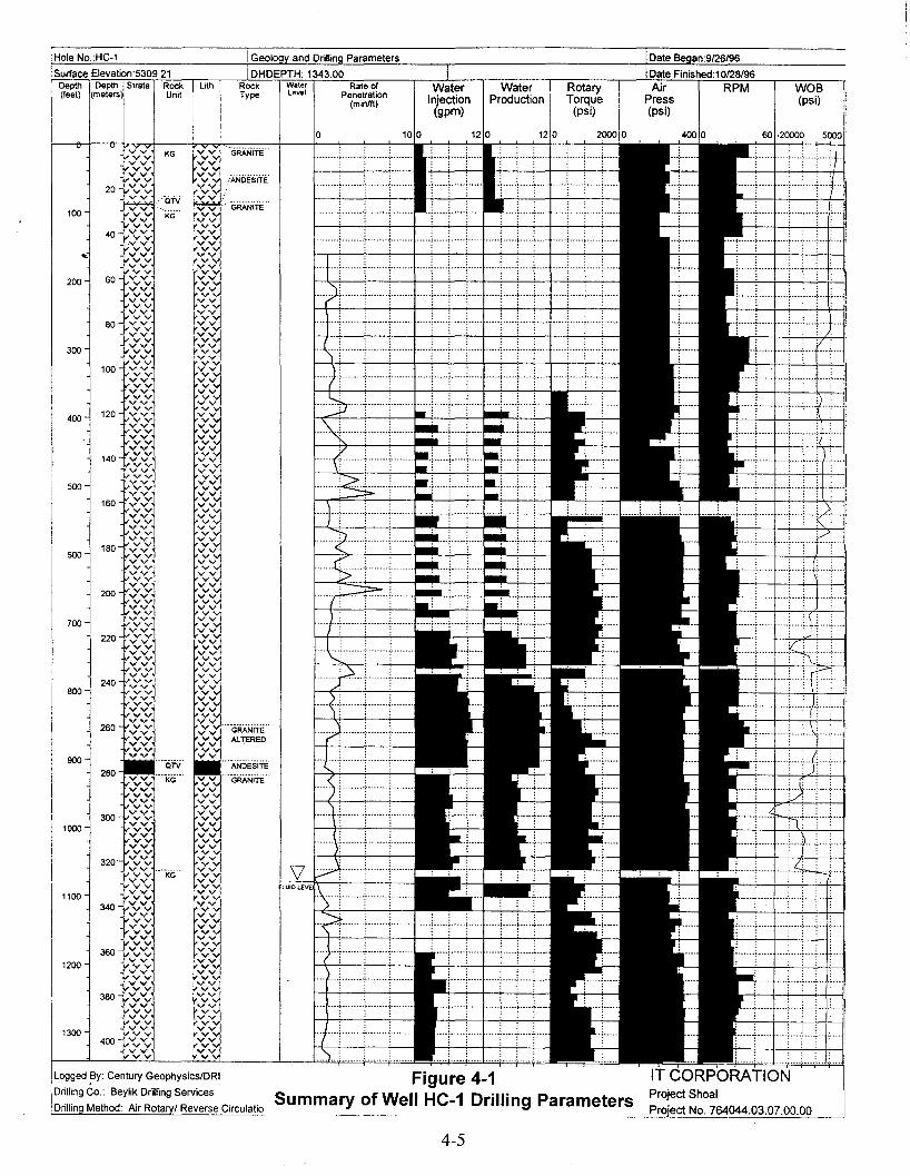
WOB(psi)
Date Finished:1 0128/96
Date an:9/26/96
Air RPMPress(psi)
RotaryTorque
(psi)
WaterProduction
WaterInjection
(gpm)
Rate ofPenetration
(minlft)
Waterlevel
Depth Depth Strata Rock Lith(feet) (meters Unit
Surface Elevation:5309.21
IHole NO.:HC-1
o 100 120 120 2000 0 400 0 60 ·20000 5000
Logged By: Century GeophysicslDRI
Drilling Co.: Beylik Drilling Services
;Drilling Method: Air Rotaryl Reverse Circulatio
IT CORPORATIONProject ShoalProject No. 764044.03.07.00.00
.....: 1"" ~ : + ···+····~····T····: :. .
-_·_···~·······1········ ·····t·····t·····~····· ·····r·····r--··t····
.: :.. ::,·······r·······1········ ·····[·····1·····1·--·· ·····f·····r····-r····
_·······~·······t-······1········
.. , ~ !.. .L. ;-- ~ ;--.+ t ..
........~ _._.~ _..~ .
········~·······_~··_·_··r·······
.......; -+-- + -I-]..·-j--··· (.+ ~ .
: :. ::: :::
········~·······t·······1·············~·····i·····~···_- ·····r·····r·····~··_·
Figure 4-1Summary of Well HC-1 Drilling Parameters
OTV
vvvv
··'KG'··vvvvvvvvvvvvvvvvvvvvvvvvvvvvvv ..-----..vv KGvvvvvvvvvvvvvvvvvvvvvvvvvvvvvvvvvvvvvvvvvvvvvvvvvvvvvvvvvvvvvvvv
600
500
200
800
400
700
900
300
100
260
3001000
320'
1100340
3601200
380
1300400
4-5
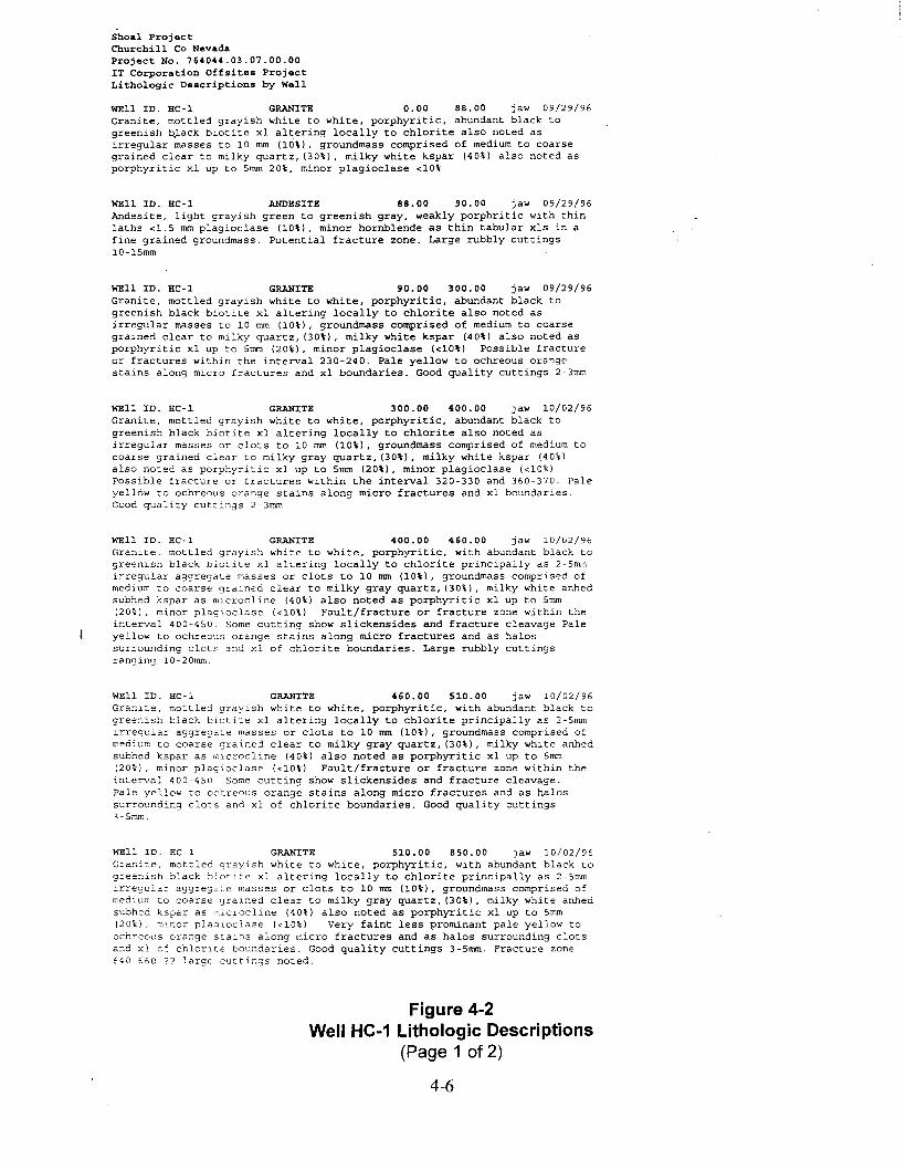
Shoal ProjectChurchill Co NevadaProject No. 764044.03.07.00.00IT Corporation Offsites ProjectLithologic Descriptions by Well
WEll ID. HC-l GRANITE 0.00 88.00 jaw 09/29/96Granite, mottled grayish white to white, porphyritic, abundant black togreenish b)ack biotite xl altering locally to chlorite also noted asirregular masses to 10 mm (10\), groundmass comprised of medium to coarsegrained clear to milky quartz, (30\), milky white kspar (40\) also noted asporphyritic xl up to 5mm 20\, minor plagioclase <10\
WEll ID. HC-l ANDESITE 88.00 90.00 jaw 09/29/96Andesite, light grayish green to greenish gray, weakly porphritic with thinlaths <1.5 mm plagioclase (10\), minor hornblende as thin tabular xIs in afine grained groundmass. Potential fracture zone. Large rubbly cuttings10-15mm
WEll ID. HC-l GRANITE 90.00 300.00 jaw 09/29/96Granite, mottled grayish white to white, porphyritic, abundant black togreenish black biotite xl altering locally to chlorite also noted asirregular masses to 10 mm (10\), groundmass comprised of medium to coarsegrained clear to milky quartz, (30\), milky white kspar (40\) also noted asporphyritic xl up to 5mm (20\), minor plagioclase «10\) Possible fractureor fractures within the interval 230-240. Pale yellow to ochreous orangestains along micro fractures and xl boundaries. Good quality cuttings 2-3mm
WEll ID. HC-l GRANITE 300.00 400.00 jaw 10/02/96Granite, mottled grayish white to white, porphyritic, abundant black togreenish black biotite xl altering locally to chlorite also noted asirregular masses or clots to 10 mm (10\), groundmass comprised of medium tocoarse grained clear to milky gray quartz, (30\), milky white kspar (40%)also noted as porphyritic xl up to 5mm (20\), minor plagioclase «10%)Possible fracture or fractures within the interval 320-330 and 360-370. Paleyellow to ochreous orange stains along micro fractures and xl boundaries.Good quality cuttings 2-3mm
WEll ID. HC-l GRANITE 400.00 460.00 jaw 10/02/96Granite, mottled grayish white to white, porphyritic, with abundant black togreenish black biotite xl altering locally to chlorite principally as 2-5mmi"regular aggregate masses or clots to 10 mm (10\), groundmass comprised ofmedium to coarse grained clear to milky gray quartz, (30\), milky white anhedsubhed kspar as microcline (40\) also noted as porphyritic xl up to 5mm(20%), minor plagioclase «10%) Fault/fracture or fracture zone within theinterval 400-450. Some cutting show slickensides and fracture cleavage Paleyellow to ochreous orange stains along micro fractures and as halossu"rounding clots and xl of chlorite boundaries. Large rubbly cuttingsranging lO-20mm.
WEll ID. HC-l GRANITE 460.00 510.00 jaw 10/02/96Granite, mottled grayish white to white, porphyritic, with abundant black togreenish black biotite xl altering locally to chlorite principally as 2-5mmirregular aggregate masses or clots to 10 mm (10%), groundmass comprised ofmedium to coarse grained clear to milky gray quartz, (30\), milky white anhedsubhed kspar as mlcrocline (40\) also noted as porphyritic xl up to 5mm(20%), minor plagioclase «10%) Fault/fracture or fracture zone within theintecval 400-450 Some cutting show slickensides and fracture cleavage.Pale yellow to ochreous orange stains along micro fractures and as halossurrounding clots and xl of chlorite boundaries. Good quality cuttings3-5mm.
WEll 1D. HC-l GRANITE 510.00 850.00 jaw 10/02/96Granite, mottled grayish white to white, porphyritic, with abundant black tog"ee~ish black biotite xl altering locally to chlorite principally as 2-5mmir"egula" aggregste masses or clots to 10 mm (10\), groundmass comprised ofmedium to coarse grained clear to milky gray quartz, (30\), milky white anhedsubhed kspar as microcline (40\) also noted as porphyritic xl up to 5mm(20%), minor plagioclase «10%) Very faint less prominant pale yellow toochreous orange stains along micro fractures and as halos surrounding clotsand xl of chlorite boundaries. Good quality cuttings 3-5mm. Fracture zone640-560 ?? large cuttings noted.
Figure 4-2Well HC-1 Lithologic Descriptions
(Page 1 of 2)
4-6

WEll ID. HC-l GRANITE 850.00 902.00 jaw 10/02/96Granite, mottled grayish white to white to light blue gray, interval isbleached and strongly choritized, some local silicification, porphyriticwith abundant chlorite after biotite, pervasive bluish green stained quartzand microcline. Fracture and micro fractures coated with stains and thincoatings of limoni~e. Rock is similar in composition to granite above yetaltered.
WEll ID. HC-l ANDESITE 902.00 923.00 jaw 10/02/96Andesite, dark grayish blue to dark gray, very fine grain to aphanitic, someunidentified dark phenocrysts « 1\) apparent. Cuttings (S-lSmm) aregenerally platey and have weak fracture/flow cleavage. Some strongly alteredgranitic cuttings 10-20 mm with strong hematite/limonite staining.Fault/fracture zone filled by an andesite dike.
WEll ID, HC-l GRANITE 923.00 1063.00 jaw 10/02/96Granite, mottled grayish white to white, porphyritic, with abundant black togreenish black biotite xl altering locally to chlorite principally as 2-Smmirregular aggregate masses or clots to 10 mm (10\), groundmass comprised ofmedium to coarse grained clear to milky gray quartz, (30\), milky white anhedsubhed kspar as microcline (40\) also noted as porphyritic xl up to Smm(20\), minor plagioclase «10\) Very faint less prominant pale yellow toochreous orange stains along micro fractures and as halos surrounding clotsand xl of chlorite boundaries. Poor quality cuttings 3-Smm with much crosscontaination with cuttings of uphole lithologies most predominated byandesite.
WEll ID. HC-l GRANITE 1063.00 1343.00 jaw 10/27/96Mixed lithologies of granite and andesite as described above. much crosscontamination from sloughing zones encountered above.
Figure 4-2Well HC-1 Lithologic Descriptions
(Page 2 of 2)
4-7
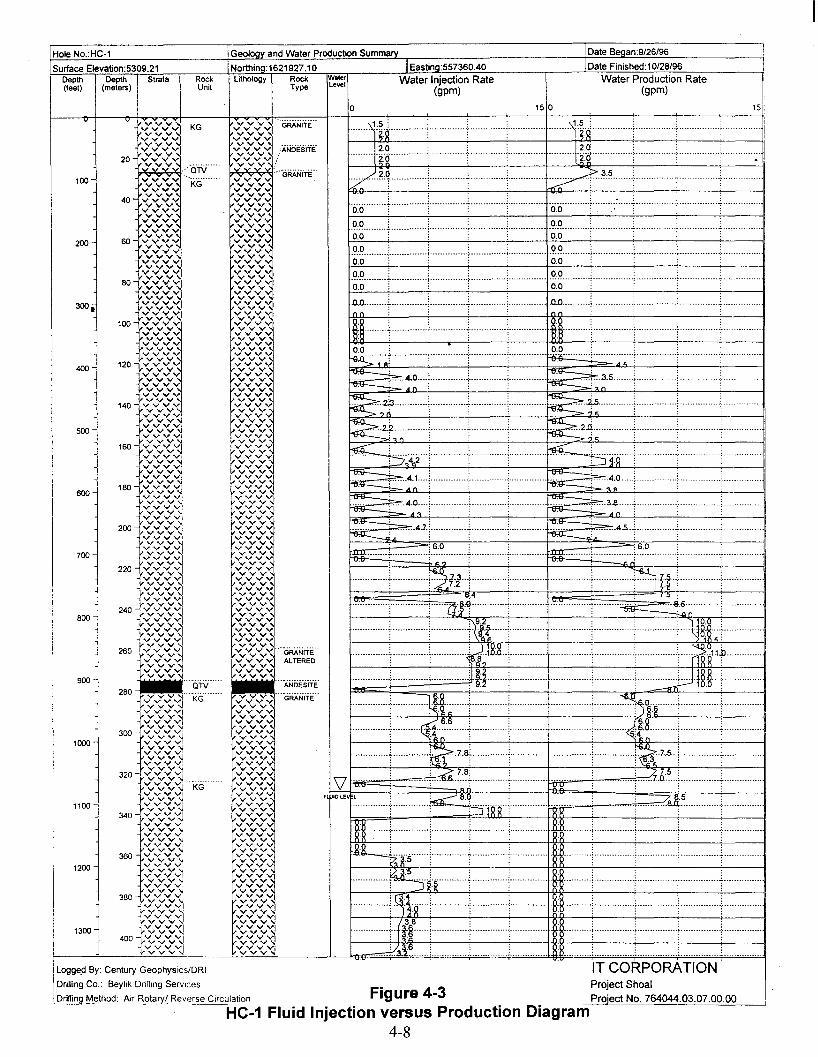
·00···h····t··············~···········-··7············ ..:-..- ·00···········;·············---'- --.-.- ; .
--·······Jl---·-·-···i---············:·········----;·-----··-··-··----·H:§---·---------·-,·······-,----······
15
::
: 7., !I.5-; 8.0---. - .
:
:
Water Production Rate(gpm)
IT CORPORATIONProject ShoalProiect No. 764044.03.07.00.00
;
;
IDate Finished: 10/28/96
1Date Beoan:9/26/96
150
Figure 4-3
~·8.q- •• -.- •••••••••:•• --- •••••••• t : :-=:JiRR ..~--
--·-··-·--····1··(~~f·-·-:·--·---·-----··i············ .. ;--------.- 1J -.---f-..- -..-f-- -············~·····-·-···--··T·-·······-····-·-._...!.3~~. _.._. __..__ _ .1 RR _._ .._ .._ _. _..__ __ ~__ ._._ _
----0-_
··············~·~r····-·--·t···-·-·······+·········-·--. ~8··········+··---·-········:··-·---·---··+········--·---i-" - --........-.- i..4:~:g + -..--+ j ._.._.. _1 ~~ +-.- ..- +.---- -.- -.-. -_ -
rH--·····+········---·+············+······--··-········...... l··-······,··-···-··-······f···-·········-·i- - -..:-.-- - -kU- : :·R. . ·'7.:·~·5·······~······-·- " -_.- -.- -........... ii""" ..L _._._l._. __ +.. _._ _+ ------
.~~ : - -+- - -+ L. ·~:·6···········f···-····-··· --~ ..--.-. - ~ ------ -.
.'?:!? .;. .j ) _ ; '?:!? .._ _-_.;_ ; ; _--.- -- _-_. __ .- .0.0: : : : 0.0; : :
~ ~- j.~~~~ t ----.-+-.··_········~·········~·· __ ···_········f·6:~ __ ._ --.l_.. l _ .
··········-···i···············t)n··i··------···-··i···· ·-----·-·--·-··+···············NH··f········-·-· --- - .··:··-·········i··········-···-i-----11:gr-········--··;---.--.-._----..~ _.~._._._-_..~.~........ -_ _.
············+···-········-j--·····-······ftit-···-:······· --.- ..-.. -[ ---..-- - ~ ..-1JM-~':"-"-'-' -.- ..
•••••••• I •••.•••••••,......... ffiI88r••••••••••••••••••·••·••• r••••••••••••••,••••••••• UUI••·•••.•••••••..............1..-..-.-.--..-\q.~ : _ __ ------ ..i ~h- ~ : _ _..
············+·:···_····~·!··~······t-···-··-··----(-············1····-- ·--·-···:···········--~t~···········[·····--· -"-'- i__+ _~_7.~ ~ _ ; _.._ ~.7.S._:_. __ .._ ..+ _.. __.__ .:..2 7.8;: : .-4 7.5 :.-----..: c.6-:.~.,t -····-·~-- --- rq:g.... . "[- --7..0.- , .
··-····\jt~········-·····:··············~········· ········ltd·······-····
;
:
~t~-·-·--··-L---.------.-:.-.-.-.- ··~1-~··-··-····-·········-
~~~-···--······+----···-·---t-·-··---·····-i.-···-·····..-.~t; --.
~.- L---.---.----L.. .. -. -- ~ -. ----. __. -- ._.~- ..- --L..-. ------ -.-- _.......... -.- --.--
~.~.~ ....•.... _ ~ _.. •__ .. __ __ .__.~.~5 ~_:_ .. _.. , _.._,.. _.. _ _ : .
~ ::?::.~~ L. +_._ --.__ '_ ~ ~_~4:0... -._.._., .. __ ....•.... _.. _ .
~.A.~~_ .. : .. __ . ._•. _._ ;_. ----.----C-iC.. ~.3~;--.--; ---,---- --.--.- .. . . . ,
~ 4.7.:_._ _..+ _._._ __~ 4.5._[- l. __ _.l _
: :::0.0. . . . _.. _._ '?!? _._.._: - -. _. : : _.. _. __·O.O········T"············~··············:···········-·-, 0.0 -, -..- , .
li~---.---·-t----.-.--··--+--·-·-··-··..+·-·-····· :._ .. ._.._..\I-E~f;;B~ --.;.-.---..-.-.-.:- ,.-.--.-- c.. -.. ~
. , .. ..a.o l.. _..L._ l. i. .a.o __ ~ l. _. _~ .. _..l_ __Inn: : : ; n n: • . ;
I/··~~T·-···-·hhh+h h·t·····--·-h-h.-.. -.- -.h····f~--3:~ .. -- -[.- .
F IDLE l
Lithology Rock Water Water Injection RateType Level (gpm)
ovvvvvvvvvvvvvvvvv
vV'vvvvvvvvvvvv
Northino:1621927.10 IEastina:557360.40
Geology and Water Production Surnrnarv
"'ANDEsiTEyv..."v""""",, "'-GRANITE-vvvvvvvvvv
vvvV'vvvvvvvvvvvvvvvvv
vvvV'vvv
vvvV'vvvvvvvvvvvvvvvvvvvvvvvvvvvvvvvvvvvvvv
vvvV'vvv
vvvV'vvvvvvvvvv
Vy""y""...",:::vvvvvvv""""vyvv""vvvvvvvvvvvvvvvvvvvvvvvvvvvvvvvvvvvvvvvvvvvvvvvvv
/ANDE'siiE
~c;>;c;>;~:., -GRANiTE'-vvvvvvvvvvvvvvvvvvvvvvvvvvvvvvvvvvvvvvvvvvvvvvvvvvvvvvvvvvvvvvvvvvvvvvvvvvvvvyvvvvvvvvvvvvvvvvvvvvvvvvvvvvvvvvvvvvvvvvvvvvvvvvvvvvvvvvvvvvvvvvvvvvvvvvvvvvvvvvvvvvvvvvvv
vvvV'vvvvvvvvvvvvvvvvvvvvvvvvvvvvvvvvvvvvvvvvvvvvvvvvvvvvvvvvvvvvvvvvvvvvvvvvvvvvvvvvvvvvvvvvvvvvvv
vvvV'vvvvvvvvvvvvvvvvvvvvvvvvvvvvvvvvvvvvvvvvvvvvvvvvvv:v:v:':: ··'GRANiTE··"'""v...""",,,\, ALTEREDvvvvvvv
RockUnit
KG
-Ciw'"-- .KG
-Ciw'..........
KG
20
280
100
40
200 60
80
300.
100
400 120
140
500
160
180600
200
700
220
240800
260
1000
1200
1100 l
Surface Elevation:5309.21
Hole NO.:HC-1
Logge.d By: Century GeophysicslDRI
Drilling Co.: Beylik Drilling Services
IDrilling Method: Air Rotary/ Reverse Circulation
I
Depth Depth Strata(feet) (meters)
HC-1 Fluid Injection versus Production Diagram4-8

Spectra Gamma RayThorium
(cps)
Date B an:9/26/96
Date Finished:10/28/96
2500
·····~·····;·····:·····(..·t····t·····;······,·····;······,·····;······,·····;······,······,·····1
····;·····'····-1-···
Spectra Gamma RayUranium
(cps)
: : : :
.....~.....,.....: . .. ,.....!.....:.....!.. ...L...
....:....
-..~ .....:...-
.. <•...• ;•••••; •••••; •••.
··-:····j····~·····;···-·~-·-·r····
···t--_·+····~·····~·· __ ·t-·_·+·
·~················; ..·t··..;·····1
"-ANDEsiTE'vv
:::V:::VJ\vv:vv :vvvvvv
"'vv", GRANiTE"vvvvvvvvvvvvvvvvvvvvvvvvvvvvvvvvvvvvvvvvvvvvvvvvvvvvvvvvvvvvvvvvvvvvvvvvvvvvvvvv
vvvvvvvvvvvvvvvvvvvvvvvvvvvvvvvvvvvvvvvv
vvvvvvvvvvvvvvvvvvvv
vvvvvvvvvvvvvvvvvvvvvvvvvvvvvvvvvvvvvvvvvvvvvvvv
vvvvvvvvvvvvvvvvvvvvvvvvvvvvvvvvvvvv
Vy "'y "1vv~vvvv~vVJ:v:vJVVvV~Jvvvvvv
"'",v", ,:GRANITE":::v:::v ,/ALTEREDvv'vvvvvvvvvvvv
vvvvvvvvvv
40 vvvvvvvvvvvvvvvvvvv
60 vvvvvvvvvvvvvvvvvvvv
80 vvvvvvvvvvvvvvvvvvvv
100 vv vvvvvvvvvvvvvvvvvv
120 v vvvvvvvvvvvvvvvvvvv
140 v v vvvvvvvvvvvvvvvvvv
160 v v vvvvvvvvvvvvvvvvvv
180 v v v
::::~vv~
200 :v:v~~vvvvv
~:::::::vv
220 vvv
J:::::vvvvvvv
240 vvvvv
ivv ",,,,,,,
vvvvvvvv'vv
260 vvvvvvvvvvvvvvv
20
40
60
80
100
120
140
160
180
200
220
240
260
280
300
320
340
360
380
400
420
440
460
480
500
520
540
560
580
600
620
640
660
680700
720
740
760
780
800
820
840
860
880
900
920940
960
980
1000
1020
10401060
1080
1100
1120
1140
1160
1180
1200
12201240
1260
1280
1300
1320
Depth Depth I Strata Rock ithol(feet) meters) Umt
I
Hole No.:HC-1
Surface Elevation:5309.21
IT CORPORATIONProject Shoal
Figure 4-4 Pro'ect No. 764044.03.07.00.00
HC-1 Geophysical Log Traces of Spectra Gamma Ray4-9
Logged By: Century Geophysics/DRI
Drilling Co.: Beylik Drilling Services
Drillin Method: Air Rota / Reverse Circulation

:/I
I~/
~
Neutron(cps)
Date Finished: 10/28/96
Date Beaan:9/26/96
500 0
/
!·z:·:: . : :~ ~ ~~::: :~
Resistivity(ohmlm)
1/7
·····;·····t····~·····T·····f·····:·····i··
200
IEasting:557360.40
Caliper(inches)
-
o
IVU10LEVl
Rock WaterType level
INorthina:1621927.10
IGeoloov and Geoohvsical Log Summary
itholog
Hole NO.:HC-1
Surface Elevalion:5309.21Depth Depth I Strata Rock(feet) metersj Unit
II
'vvu vvvvvvvvvvvvvvvvvvvv
1020 vvvvvvvvvvvvvvvvvvvvvv
1040vvvvvvvvvvvvv
320vvvvvvvvvvvv
1060 vvvvvvvv "'-KG"vvvvvvvvvvvvvvv
tV V
1080 vvvvvvvvvv~vvvvv
fVVvvvvv
1100 vvvvvvvvvv
JVVvvvvvvvv
340 rv vv v1120 vv
vvvvvvvv
1~:~11140vvvvvvvvvvvvv
"'VV~vv vtvVvvvvv
1160 vvvvv
-!.vvv
fVVvvvvvvvvvv
1180vv
360 vvvv"""vvvvvvvvvv
1200 t:t::l~vvvvvvvvvv~vvv
t vY .....-"""......
IV""".....-"""......1220 f::lvv
vvvvvvvvvv
1240 vvvvvvvv
380 vVvVlvvvvv
vVvVlvv1260
fV:V:
VVIvvvvvvvvvv~vvv
1280_VVIV"""Vrvvvvvvv
vvvv1vvvvvvvv
1300 vv"""v""".....v1vv~
tv v1320
vvvvvvvvvvvvvvvvvvvvvvvvvvvvvv
Figure 4-5
IT CORPORATIONProject Shoal
Project No. 764044.03.07.00.00
HC-1 Geophysical Log Traces of Caliper, Resistivity, Neutron4-10
Loggeq By: Century GeophysicslDRI
Drilling Co.: Beylik Drilling Services
Drillina Method: Air Rotarv/ Reverse Circulation
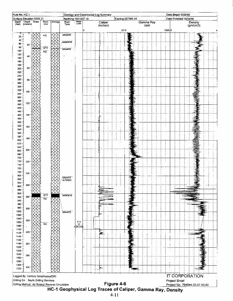
Hole No.:HC-1 iGeoloov and GeoonvsicatLog Summary Date Began:9/26/96
INorthing:1621927.10 IEastina:557360.40Surface Elevation:5309.21Depth I Depth Strata Rock(feel) lmetersl. Unit
II
!
itholog Rock WaterType level
o
Caliper(inches)
200
Gamma Ray(api)
Date Finished:10/28/96
Density(gmlcm3)
1000 0
,-- ...._~_ ..._~._-_.: .....:..... ~_....~-_ ...+....
. .; ~.~ -+ "-
·····•·..·····....·..··..······3;:;·····;······:·····;·..··1
..... i ......;..... ;...... :.... ~ ..-:oll>.i-: t.
j :i-. . . . -i:~:=:,... ,......;.....;....1•••••<••••••, ••••-<-....., ..•••~ "
;..:..... ;......; .....;......; .....-'-"'.;'-'=.. ;zo..... ,...····:·....;..·..1
:J:: ~ ~
..·..·..·....······..········:·I···~·:
, : ~-'-.....:--1
:""............ ',-,:
:~
IT CORPORATIONProject Shoal
Proiect No. 764044.03.07.00.00
··~·····-:·····:·····t··_··-..- _._--
: : :
Tt!'i L-
:
:...., ; , , '1" , ; .
=·..:· .. ··~·····,·····:· .. ·· ..;·····,······,····t·····;··· ; ; .
:
t- ..··,·· , -t- ,·.. •..·,······,······,····t·········· .
: :
:-..... ,......,......,..... ,..... ,..... ,......:..... i Li,~:;..~·· ..,.. ····;· ..·..:.... ·,~
: , :
:,
:--...
~~
.--0- ~
~
~
Figure 4-6
~; ,~: ;
·t-····f···· -r ····1--- .-~ ..--:
~ ~
····_················t·..·.,····,·····,··..·,· ...., ....t
······················r-···~····;·····:·· ..·:·....: ....t
f··..·,....;....-i.. ···;f···~····;·····;·····;·· ..~····t··1
f·····,····:······;····-l ..··~ ..··;·....;·....;·..·~····t····..
0=;;;;;;. :
t....·,..··,..···,···+····,····,,·····,..···,·....,····t ..··
f·····, ....·;·· ..·:····~ ..··~····;·····;·····;···~· ..t·····
f·····' ..··<.. · .. , .. ··~·· .. ·,···· ..:·····, .. ···,·····,····t·· ...
f·····'.. ·+.. ·..,· ..~· ..;..···; ..···,····:·····:···j·····!
v • v v v.vv 'GRANiTE"20 -vvV' KG yVV!'vV' VV40
:vvv yVV- v v vv ..............
1""v,," "vV v ./ANDESITE60 vv20 l-"vvv~ "vV v
80~
/aN ~ >GRANiiii"..........100 -vv KG vvvvv120 "iVYV "vvvrvv vv4O-fvvv yVV140 !"'vV' vv
-lVVV' yVV160 rvv vv
""1 V V V yVV180
II"VV vv"V'vv yVVrvv vv
200 6°1"v",," vvvvv
220...vvv "vvv"vV' vv'"":vvv vvvvv240 rvv....~vvvvv ':I": v260 vv
8°1vvvvv 'y":vvv280 -lV'V""
~": v"",""v..., vv300 ~vvrvv vv
).V v v ~vv320 vv vv1°01"vvv~ ~vv
340 vvl,.vvv ~vv
360vv vv-,vvv ~vvrvv vv
380 1-vv v ~": v120 -iv",,"..., vv
400 vVvlvv,,"..., vv
vVv420 ~vv vv
l,.vvv vVv440 ~vvvvv vv
rvv vVvvv460 1401.v v v vVv
lVV"""" vv480 vVvvv vv500 r",,",,"" vVvvvlV'v" vVv520 160 ",,,",,V,, vv
~vv540 tv""",, vv
~~vvv560 -IvY...,."...,
~~vvv-vv
""1i-vv v lY~vVvvv
180l,.V,,",," f,..-vv600 vv-!vvv f,..-vv620 rvv vv
""ivvv "vV v~vvvvv vv
640 "vV v"vV' vv660 200 -'~vvVV'v "vV vvv{vvv "vV v680 vv vvvvv vVv700 ~vvvvv vv
"vV v720
-vv vv220~vvvvv vVvvv
740 '""1vvv vVvrvv vv760 "'''VV'
C"~v~~~rvv"'iVVV
780- v v ~ ~vv240....jv v v v v'
800 rvv
~~l/~~1VVVrvv
820 "1vvv.. vv~
840 ·4vvv vV' :rvv vv·860 2601.",,'(.." vv
vv~vvv vv
880 _vv vv-4vvv vv900 r v v vv
"'-aN .._-.-------....280
ANDESITE920 r v v vvKG940 t V V V vvvv VV
-4VVV VV960 Ivvvvv vv
980 ~vv -..: r"300fVVVV vv
vv1000 vvv vv GRANiTE"vv vv1020 ",,"v\ vv
vv1040
vvv vv320.1vvvvv
r~1060 tV:V:V"'-KG" vv IV1080 vv{"vV' vv F UtDLEVI. vv
~~~I1100 vvv
1120 34Oiv:~v.Jvvv
1140 lV'''",''..."1160 1
rvv-lVYV
• v v ~1180~ 360-jvvv
t V V1200 vvv
ivvvvv
m"~-t.vvvvv
r~j1240 380 i.v~v~v1260 vv-1vvv vv
Ivvvvv vv1280 vvvv vv1300 vvv vvvv vv
400 vvv vv1320 vv vvvvv ivv vvv vv
Logged.By: Century Geophysics/DRI
Drilling Co.: Beylik Drilling Services
Drillino Method: Air Rotarv/ Reverse Circulation
HC-1 Geophysical Log Traces of Caliper, Gamma Ray, Density4-11
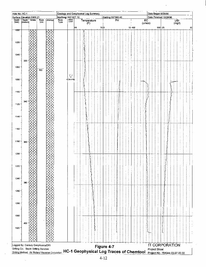
INorthing:1621927.10 IEaslino:557360.40Rock Waler Temperature PHType Level (F)
Date Began:9/26/96,'Hole NO.:HC-1
Surface Elevalion:5309.21Depth Depth! Strata Rock(feet) meters1 Unrt
Lrtl"1Olog
IGeoloav and Geoohvsical Loa Summary
65 706 10450
Date Finished: 10/28/96
EC(urnos)
550 -25
LiBr(mg/l)
50
:
.....(;...;....;...<.....;....+....;....;:t--;....;....c... ;.... ;.... ;.....;... j
: :: t-r-: :
: ::
: R:
: ::
jI
IVVV
1020
1040
1060
1080
1100
1120
1140
1160
1180
1200
1220
1240
1260
1280
1300
1320
,VUID W;; l
: :
... ~ ···l···t···l····r···~····~···r···l···
:
: ::
:
:
:
"'T"';-"T"';"'T ...."..···,····.:.···.:.···.:.···,·····,· ..·,····'..··1
IT CORPORATIONProject ShoalProiect No. 764044.03.07.00.00
Figure 4-7HC-1 Geophysical Log Traces of Chemtool
-------~-------~----.._~ ----_ .._-----_. ~---'-'-==-=-:..:...:=.:...::..:..::.:....:.:..::.::.=.:..:.::.::.:.=_-
ILogged By: Century GeophysicslDRI
IDrilling Co.: Beylik Drilling Services
IDrilling Method: Air Rotaryl Reverse Circulation
4-12

Geoloav and Tritium in Fluids.Hole No.:HC-1
:Surface Elevation:5309.21Depth Depth I Strata(feel) (meters) i
I
RockUnrt
Northina:1621927.10Lithology Rock
TypeW.terlevel
IEastina:557360.40
o
IDate Beaan:9/26/96
IDate Finished:10/28/96
Tritium in Fluids(pCill)
BOO
....+ _----- ; ---- .
-. .. .--- ----- + ~ _._ -.- .
•
•-----_.
..................... ~;; , ..~~.. :.
~ ; i .
···T-·····························-t·········· __ ·__ ··· +._._ ~ .
.. ·· · ~ ..·..t ··· ·..· ·· · · " ..
•
.....~.
..... :·······························t······ , .
..............................._ .
.........~ .
................................: _-_. _.--..--.-.----. _.._. -: _ '" ----" -- - "';" -- ~ .
/' ;
~ t" .
..............................._ :.~
·······························t················~····· + .
......................................................
······························~·············~t········ .
..............................~ ~ , .
~ : ! ; ..
~ ;
l/ _ .
UIOLEII1 L ~~.:.~.._~=:: , : ; ..
400
300
200
100
Loggeq By: Century Geophysics/DRI
Drilling Co.: Beylik Drilling Services
I Drilling Method: Air Rotary/ Reverse Circulation
IT CORPORATIONFigure 4-8 Project Shoal
HC-1 Tritium Concentrations During Drilling Proiect No. 764044.03.07.00.00
4-13

Hole NO.:HC-1 IGeology and Well Construction Summary
Surface Elevation:5309.21 INorthina:1621927.10 IEastinc557360.40
IDate Began:9/26/96
IDate Finished:1 0/28/96Depth Depth IStrata Rock I Lith Rock Waler Caliper(feet) (meters) II Unit I Type Level (inches)
o 20
Well Construction
u
20
40
60
80
100
120
140
160
1BO
200
220
240
260
2BO
30D
320
340
360
3BO
400
420
440
460
4BO
SOD
S20
540
560
SBO
600
620
640
660
6BO
700
720
740
760
7BO
BOOB20
B40
B60
BBO
90D
920
940
960
9BO
1000
1020
1D40
1060
1DBO
1100
1120
1140
1160
1180
1200
1220
1240
1260
1280
1300
1320
Logged By: Century GeophysicslDRI
Drilling Co.: Beylik Drilling Services
Drillina Method: Air Rotaryl Reverse Circulation
UIDlE
····:···T···~····: ···j····f··+·+··+····~::5..... " ~
::•••:•••',:[::••••L,~...............;.... ...~.... .;. .... ~.... ~ ····f···
..... ----..-.-.'p_._. -... ~-·-·t-... ~.... ~ ....~...: ::: :
····1····;-···_;···· --··i-···t····t·_--·-_··_~····
... "j'" -~- ---r'" ...·i·.. ··~-... ~....;....~....
••••••••• -- •• -P •••••••• ~•••• -=- ....: .... ~- .. -7 •• -
·········_········~····;:···~····:····:····~····I
--·-1····~···_~···
····j·····:-····r···· ····r-···:-_·· .-.- ----T---
:-----'-;!
:-.•"-'
f···+····.·····,····i--·,·····:·····;·····, ... :...
4-14
BOREHOLE 12" 0-101.7
CEMENT
CASING 8.625" 0 -101.7
CENTRALIZER 95.0 - 97.0
~ CASING 5.50" 0-1094.00-
r---- BOREHOLE 8.0" 101.7-1343.0
V FILL 1324.8-1343.0
++++++++++ . ++.+-::::..++++ + :~~~~+:::
IT CORPORATION

Well Coordinates(State Planar NAD 27)N: 1621981.797E: 557638.410
Clamp/ Landing Plate
Well Pad
1.22 m x 1.22 m x 0.15 m(48 in x 48 in x 6 in)Reinforced with a 152-cm x 15.2-cm(6 in x 6 in) wire mat
1.22 m
(48 in)
Protective Casing
3238-cm (12 3/4 in) od0.32-cm (.125 in) wall
Surface Casing
21.91-cm (8 5/8 in) od0.48-cm (.188 in) wall
Intermediate Casing
13.97-cm (5 1/2 in) od12.70-cm (5.0 in) id
Data Logger Access Tube
3.81-cm (1 1/2 in) conduit
Shelter for Data Logger
60.96-cm (24 in) diameter pad
Plan View
Lockable Lid
Concrete Pad
Data Logger Access Tube
(5 1/2 in) od Threaded Coupling
Intermediate Casing with 13.97-cm
32.38-cm (12 3/4 in)od Protective Casing
Cap 13.97-cm (5 1/2 in) od Threaded
/?S\ ~E .soL{) L{)C") Nu:i
E .sor- 0
N ui~
Eo £;"': L{)
r-r--: u:i~
0 •E .~ :.o;; L{)
r-
'" ui0 •
." 1/\ 1}..\7\1'f'\l
Clamp/Landing Plate
Ground SurfaceElevation1618.25 m(5309.21 tt)
Figure 4-10HC-1 Well Head Completion Diagram
4-15
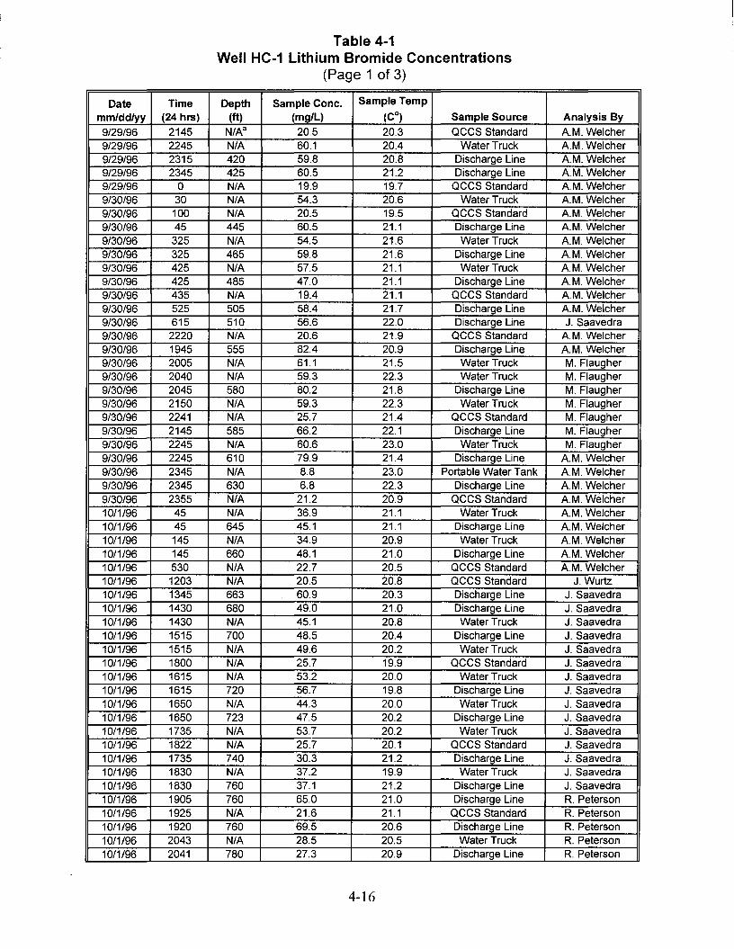
Table 4-1Well HC-1 Lithium Bromide Concentrations
(Page 1 of 3)
Date Time Depth Sample Conc. Sample Temp
mm/dd/yy (24 hrs) (ft) (mg/L) (Co) Sample Source Analysis By
9/29/96 2145 N/As 20.5 20.3 accs Standard A.M. Welcher9/29/96 2245 N/A 60.1 20.4 Water Truck A.M. Welcher9/29/96 2315 420 59.8 20.8 Discharge Line AM. Welcher9/29/96 2345 425 60.5 21.2 Discharge Line AM. Welcher9/29/96 0 N/A 19.9 19.7 accs Standard AM. Welcher9/30/96 30 N/A 54.3 20.6 Water Truck AM. Welcher9/30/96 100 N/A 20.5 19.5 accs Standard AM. Welcher9/30/96 45 445 60.5 21.1 Discharge Line AM. Welcher9/30/96 325 N/A 54.5 21.6 Water Truck AM. Welcher9/30/96 325 465 59.8 21.6 Discharge Line AM. Welcher9/30/96 425 N/A 57.5 21.1 Water Truck AM. Welcher9/30/96 425 485 47.0 21.1 Discharge Line AM. Welcher9/30/96 435 N/A 19.4 21.1 accs Standard AM. Welcher9/30/96 525 505 58.4 21.7 Discharge Line AM. Welcher9/30/96 615 510 56.6 22.0 Discharge Line J. Saavedra9/30/96 2220 N/A 20.6 21.9 accs Standard AM. Welcher9/30/96 1945 555 82.4 20.9 Discharge Line AM. Welcher9/30/96 2005 N/A 61.1 21.5 Water Truck M. Flaugher9/30/96 2040 N/A 59.3 22.3 Water Truck M. Flaugher9/30/96 2045 580 80.2 21.8 Discharge Line M. Flaugher9/30/96 2150 N/A 59.3 22.3 Water Truck M. Flaugher9/30/96 2241 N/A 25.7 21.4 accs Standard M. Flaugher9/30/96 2145 585 66.2 22.1 Discharge Line M. Flaugher9/30/96 2245 N/A 60.6 23.0 Water Truck M. Flaugher9/30/96 2245 610 79.9 21.4 Discharge Line AM. Welcher9/30/96 2345 N/A 8.8 23.0 Portable Water Tank AM. Welcher9/30796 2345 630 6.8 22.3 Discharge Line AM. Welcher9/30/96 2355 N/A 21.2 20.9 occs Standard AM. Welcher10/1/96 45 N/A 36.9 21.1 Water Truck AM. Welcher10/1/96 45 645 45.1 21.1 Discharge Line AM. Welcher10/1/96 145 N/A 34.9 20.9 Water Truck AM. Welcher10/1/96 145 660 48.1 21.0 Discharge Line AM. Welcher10/1/96 530 N/A 22.7 20.5 occs Standard AM. Welcher10/1/96 1203 N/A 20.5 20.8 accs Standard J.Wurtz10/1/96 1345 663 60.9 20.3 Discharge Line J. Saavedra10/1/96 1430 680 49.0 21.0 Discharge Line J. Saavedra10/1/96 1430 N/A 45.1 20.8 Water Truck J. Saavedra10/1/96 1515 700 48.5 20.4 Discharge Line J. Saavedra10/1/96 1515 N/A 49.6 20.2 Water Truck J. Saavedra10/1/96 1800 N/A 25.7 19.9 accs Standard J. Saavedra10/1/96 1615 N/A 53.2 20.0 Water Truck J. Saavedra10/1/96 1615 720 56.7 19.8 Discharge Line J. Saavedra10/1/96 1650 N/A 44.3 20.0 Water Truck J. Saavedra10/1/96 1650 723 47.5 20.2 Discharge Line J. Saavedra10/1/96 1735 N/A 53.7 20.2 Water Truck J. Saavedra10/1/96 1822 N/A 25.7 20.1 accs Standard J. Saavedra10/1/96 1735 740 30.3 21.2 Discharge Line J. Saavedra10/1/96 1830 N/A 37.2 19.9 Water Truck J. Saavedra10/1/96 1830 760 37.1 21.2 Discharge Line J. Saavedra10/1/96 1905 760 65.0 21.0 Discharge Line R. Peterson10/1/96 1925 N/A 21.6 21.1 accs Standard R. Peterson10/1/96 1920 760 69.5 20.6 Discharge Line R. Peterson10/1/96 2043 N/A 28.5 20.5 Water Truck R. Peterson10/1/96 2041 780 27.3 20.9 Discharge Line R. Peterson
4-16

Table 4-1Well HC-1 Lithium Bromide Concentrations
(Page 2 of 3)
Date Time Depth Sample Cone. Sample Temp
mm/dd/yy (24 hrs) (tt) (mg/L) (Co) Sample Source Analysis By10/1/96 2049 780 28.7 20.7 Discharge Line R. Peterson10/1/96 2130 780 31.3 21.2 Discharge Line R. Peterson10/1/96 2145 N/A 20.9 20.0 accs Standard R. Peterson10/1/96 2150 780 33.2 20.4 Discharge Line AM. Welcher10/1/96 2345 N/A 19.3 20.4 accs Standard AM. Welcher10/2/96 105 790 34.1 21.2 Discharge Line R. Peterson10/2/96 150 803 31.9 20.1 Water Truck R. Peterson10/2/96 135 800 37.0 21.4 Discharge Line R. Peterson10/2/96 245 N/A 23.3 20.6 accs Standard R. Peterson10/2/96 220 820 36.0 21.7 Discharge Line R. Peterson10/2/96 320 830 37.3 21.5 Discharge Line AM. Welcher10/2/96 420 845 32.6 21.2 Discharge Line AM. Welcher10/2/96 455 N/A 41.5 20.1 Water Truck AM. Welcher10/2/96 510 N/A 24.0 20.3 accs Standard AM. Welcher10/2/96 530 N/A 23.7 20.4 accs Standard A.M. Welcher10/2/96 520 N/A 38.2 20.6 Water Truck AM. Welcher10/2/96 520 865 32.6 22.1 Discharge Line AM. Welcher10/2/96 544 880 43.3 19.6 Water Truck R. Peterson10/2/96 610 895 36.9 21.2 Discharge Line R. Peterson10/2/96 610 N/A 34.9 21.3 Water Truck R. Peterson10/2/96 640 920 30.9 22.5 Discharge Line R. Peterson10/2/96 735 N/A 25.4 20.9 accs Standard R. Peterson10/2/96 800 940 40.4 19.2 Discharge Line J Saavedra10/2/96 800 N/A 40.2 19.1 Water Truck J Saavedra10/2/96 910 N/A 8.4 18.9 PT J Saavedra10/2/96 910 960 44.5 18.9 Discharge Line J Saavedra10/2/96 1025 N/A 22.7 19.0 accs Standard J Saavedra10/2/96 940 N/A 38.1 20.7 Water Truck J Saavedra10/2/96 1045 N/A 38.8 20.6 Water Truck J Saavedra10/2/96 1045 980 46.8 20.5 Discharge Line J Saavedra10/2/96 1356 N/A 20.0 21.4 accs Standard J Saavedra10/2/96 1150 N/A 26.3 22.2 Water Truck J Saavedra10/2/96 1150 1000 38.4 21.2 Discharge Line J Saavedra10/2/96 1245 N/A 31.7 22.0 Water Truck J Saavedra10/2/96 1245 1015 35.6 21.0 Discharge Line J Saavedra10/2/96 1345 N/A 43.8 21.8 Water Truck J Saavedra10/2/96 1422 N/A 26.3 21.2 accs Standard J Saavedra10/2/96 1345 1030 31.1 21.3 Discharge Line J Saavedra10/2/96 1445 N/A 26.7 21.8 Water Truck J Saavedra10/2/96 1445 1045 32.9 20.5 Discharge Line J Saavedra10/2/96 1615 N/A 27.4 21.6 PT J Saavedra10/2/96 1615 1050 31.9 20.4 Discharge Line J Saavedra10/2/96 1759 N/A 29.4 19.9 accs Standard J Saavedra10/2/96 1635 N/A 27.8 20.9 PT J Saavedra10/2/96 1635 1060 32.6 20.4 Discharge Line J Saavedra10/2/96 1800 1063 30.1 21.5 Discharge Line J Saavedra10/2/96 2245 N/A 20.5 20.6 accs Standard R. Peterson10/2/96 1950 Purge at 106 31.7 19.8 Discharge Line R. Peterson10/2/96 2035 Purge at 106 30.1 20.7 Discharge Line R. Peterson
10/2/96 2130 Purge at 106 NDb Lead N/A Discharge Line R. Peterson10/2/96 2145 Purge at 106 ND Lead N/A Discharge Line R. Peterson10/2/96 2125 N/A 20.0 21.9 Water Truck R. Peterson10/2/96 2135 N/A 18.2 20.9 accs Standard R. Peterson10/2/96 2215 Purge at 106 24.1 22.6 Discharge Line R. Peterson
4-17
I
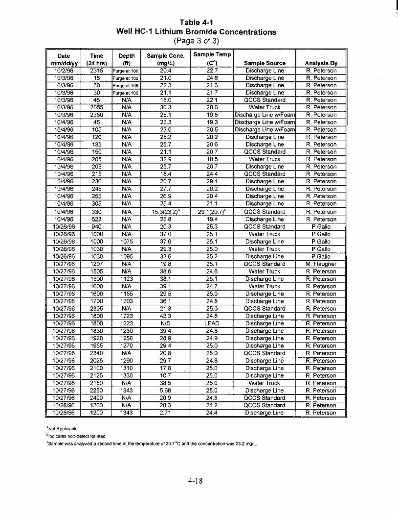
Table 4-1Well HC-1 lithium Bromide Concentrations
(Page 3 of 3)
Date Time Depth Sample Conc. Sample Temp
mm/dd/yy (24 hrs) (ft) (mg/L) (Co) Sample Source Analysis By1012/96 2315 Purge at 106 20.4 22.7 Discharge Line R. Peterson10/3/96 15 Purge at 106 21.0 24.6 Discharge Line R. Peterson10/3/96 30 Purge at 106 22.3 21.3 Discharge Line R. Peterson10/3/96 30 Purge at 106 21.1 21.7 Discharge Line R. Peterson10/3/96 45 N/A 18.0 22.1 accs Standard R. Peterson10/3/96 2055 N/A 30.3 20.0 Water Truck R. Peterson10/3/96 2350 N/A 25.1 19.5 Discharge Line w/Foam R. Peterson10/4/96 45 N/A 23.3 19.3 Discharge Line w/Foam R. Peterson10/4/96 105 N/A 23.0 20.5 Discharge Line w/Foam R. Peterson10/4/96 120 N/A 25.2 20.2 Discharge Line R. Peterson10/4/96 135 N/A 25.7 20.6 Discharge Line R. Peterson10/4/96 150 N/A 21.1 20.7 accs Standard R. Peterson10/4/96 205 N/A 32.9 18.5 Water Truck R. Peterson10/4/96 205 N/A 25.7 20.7 Discharge Line R. Peterson10/4/96 215 N/A 18.4 24.4 accs Standard R. Peterson10/4/96 230 N/A 20.7 29.1 Discharge Line R. Peterson10/4/96 245 N/A 27.7 20.2 Discharge Line R. Peterson10/4/96 255 N/A 26.9 20.4 Discharge Line R. Peterson10/4/96 305 N/A 25.4 21.1 Discharge Line R. Peterson
10/4/96 330 N/A 15.3(23.2)c 29.1(20.7)c accs Standard R. Peterson10/4/96 523 N/A 25.8 19.4 Discharge Line R. Peterson
10/26/96 940 N/A 20.3 25.3 accs Standard P.Galio10/26/96 1000 N/A 37.0 25.1 Water Truck P.Galio10/26/96 1000 1075 37.6 25.1 Discharge Line P.Galio10/26/96 1030 N/A 29.3 25.0 Water Truck P.Galio10/26/96 1030 1095 32.6 25.2 Discharge Line P.Galio10/27/96 1207 N/A 19.8 25.1 accs Standard M. Flaugher10/27/96 1505 N/A 38.6 24.6 Water Truck R. Peterson10/27/96 1500 1123 38.1 25.1 Discharge Line R. Peterson10/27/96 1600 N/A 39.1 24.7 Water Truck R. Peterson10/27/96 1600 1155 29.5 25.0 Discharge Line R. Peterson10/27/96 1700 1203 36.1 24.8 Discharge Line R. Peterson10/27/96 2305 N/A 21.3 25.0 accs Standard R. Peterson10/27/96 1800 1223 43.3 24.8 Discharge Line R. Peterson10/27/96 1800 1223 N/D LEAD Discharge Line R. Peterson10/27/96 1830 1230 39.4 24.8 Discharge Line R. Peterson10/27/96 1920 1250 28.9 24.9 Discharge Line R. Peterson10/27/96 1955 1270 29.4 25.0 Discharge Line R. Peterson10/27/96 2340 N/A 20.8 25.0 accs Standard R. Peterson10/27/96 2025 1290 29.7 24.8 Discharge Line R. Peterson10/27/96 2100 1310 17.8 25.0 Discharge Line R. Peterson10/27/96 2125 1330 10.7 25.0 Discharge Line R. Peterson10/27/96 2150 N/A 38.5 25.0 Water Truck R. Peterson10/27/96 2250 1343 5.68 25.0 Discharge Line R. Peterson10/27/96 2400 N/A 20.9 24.5 accs Standard R. Peterson10/28/96 1200 N/A 20.3 24.2 accs Standard R. Peterson10/28/96 1200 1343 2.71 24.4 Discharge Line R. Peterson
'Not Applicable
"lndtcates non-detect for lead.
"samoie was analyzed a second time at the temperature of 20.7 "C and the concentration was 23.2 mg/L.
4-18
I

Table 4-2Well HC-1 Water Level Measurements
Well Name Date Depth to Elevation NotesFluid (ft) (ft)
HC-1 01-0ct-96 717.14 4592.07 Water level from depth to water check with drill pipe. Depth of well at this point is 783.0 ft.
HC-1 05-0ct-96 942 4367.21 Fluid level obtained from Century geophysics neutron log.
HC-1 08-0ct-96 920 4389.21 Fluid level DRI with tape. Accuracy not considered good.
HC-1 09-0ct-96 956 4353.21 Water level determined to top of casinq usinq DRI down hole video camera.
HC-1 14-0ct-96 959.1 4350.11 Fluid level determined from DRI transducer installed well.
HC-1 15-0ct-96 962 4347.21 Fluid level determined via DRI transducer in well. Measured to qround level (GL).
HC-1 16-0ct-96 964.72 4344.49 Depth to water obtained from DRI tranducer set in well. Measured to GL.
HC-1 21-0ct-96 975.99 4333.22 DRI transducer readlnq to top of conductor caslnq, approx. 1 ft above GL. Value adjusted to GL.
HC-1 22-0ct-96 977.11 4332.1 DRI transducer readinq adiusted for qround level.
HC-1 23-0ct-96 978.91 4330.3 DRI transducer readinq. Measured to top of conductor caslnq, at 1 ft above GL.
HC-1 29-0ct-96 1081.71 4227.5 Water level obtained bv IT Corp. usinq solinist tape.
HC-1 01-Nov-96 1079 4230.21 DRI water level obtained from top of surface casino, stick-up aoorox, 1 ft. Value adlusted to GL.HC-1 13-Nov-96 1078 4231.21 Water level approx. obtained from the DRI down hole video camera measured to GL.

~I
No
Table 4·3Well HC-1 List of Geophysical Logs
Well Name Geophysical Date Log Top Log Bottom Logging
Log Logged (tt) (tt) Company
HC-1 3-Arm Caliper 10/5/96 0.00 902.70 Century Geophysical
HC-1 3-Arm Caliper 11/6/96 1014.10 1323.80 Century Geophysical
HC-1 3-Arm Caliper 9/9/96 915.00 1028.00 DRI
HC-1 Density/Resistivity/Neutron/Neutron Porosity 10/5/96 0.00 1030.90 Century Geophysical
HC-1 Density/Resistivity/Neutron/Neutron Porosity 11/6/96 1003.10 1324.90 Century Geophysical
HC-1 Deviation - magnetic 10/6/96 0.10 1028.70 Century Geophysical
HC-1 Deviation - gyroscopic 11/7/96 0.60 1326.00 Century Geophysical
HC-1 Spectra Gamma Ray (K, U, Th) 10/5/96 1.90 1028.50 Century Geophysical
HC-1 Spectra Gamma Ray (K, U, Th) 11/6/96 1015.90 1324.00 Century Geophysical
HC-1 Temperature 10/5/96 625.50 1029.30 Century Geophysical
HC-1 Temperature 11/6/96 915.90 1324.60 Century GeophysicalHC-1 Acoustic Borehole Televiewer 11/6/96 1099.24 1324.25 Century GeophysicalHC-1 Chemtool 11/14/96 1082.00 1327.00 DRIHC-1 Downhole Video Camera 10/4/96 0.00 889.00 DRI
Note: Calibrations and repeat sections were performed per contract specifications.
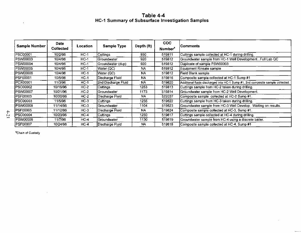
~I
tv......
Table 4-4HC-1 Summary of Subsurface Investigation Samples
Date COCSample Number
CollectedLocation Sample Type Depth (ft)
Numbera Comments
PSCOOO01 10/2/96 HC-1 Cuttings 930 519811 Cuttings sample collected at HC-1 during drilling.
PSWOOO03 10/4/96 HC-1 Groundwater 920 519812 Groundwater sample from HC-1 Well Development...Full Lab QC
PSWOOO04 10/4/96 HC-1 Groundwater (dup) 920 519812 Duplicate of sample PSWOOO03PSWOOO05 10/4/96 HC-1 Water (QC) NA 519812 Equipment Rinsate samplePSWOOO06 10/4/96 HC-1 Water (QC) NA 519812 Field Blank samplePSFOOO01 10/5/96 HC-1 Discharge Fluid NA 519816 Composite sample collected at HC-1 Sump #1PCXOOO01 11/3/96 HC-1 2nd Discharge Fluid NA 519820 Additional fluids discharged into HC-1 Sump#1, 2ndcomposite samplecollected.PSCOOO02 10/16/96 HC-2 Cuttings 1253 519813 Cuttings sample from HC-2 taken during drilling.PSWOOO07 10/21/96 HC-2 Groundwater 1173 519814 Groundwater sample from HC-2 Well Development.PSFOOO03 10/20/96 HC-2 Discharge Fluid NA 522037 Composite sample collected at HC-2 Sump #1.PSCOOO03 11/5/96 HC-3 Cuttings 1255 519822 Cuttings sample from HC-3 taken during drilling.PSWOOO08 11/14/96 HC-3 Groundwater 1104 519823 Groundwater sample from HC-3 Well Develop. Waiting on results.PSFOOO05 11/12/96 HC-3 Discharge Fluid NA 519824 Composite sample collected at HC-3, Sump #1.PSCOOO04 10/23/96 HC-4 Cuttings 1250 519817 Cuttings sample collected at HC-4 during drilling.PSWOOO09 11/7/96 HC-4 Groundwater 1130 519819 Groundwater sample from HC-4 using a discrete bailer.
PSFOOO07 10/24/96 HC-4 Discharge Fluid NA 519818 Composite sample collected at HC-4, Sump #1
·Chain of Custody
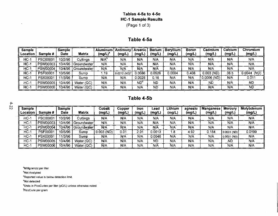
~I
NN
Tables 4-5a to 4-5eHC-1 Sample Results
(Page 1 of 3)
Table 4-5a
Sample Sample Aluminum Antimony Arsenic Barium Beryllium Boron Cadmium Calcium ChromiumLocation Sample # Date Matrix (mg/L)a (mg/L) (mg/L) (mg/L) (mg/L) (mg/L) (mg/L) (mg/L) (mg/L)
HC-1 PSCOOO01 10/2/96 Cuttings N/Ab N/A N/A N/A N/A N/A N/A N/A N/AHC-1 PSWOOO03 10/4/96 Groundwater N/A N/A N/A N/A N/A N/A N/A N/A N/AHC-1 PSWOOO04 10/4/96 Groundwater N/A N/A N/A N/A N/A N/A N/A N/A N/AHC-1 PSFOOO01 10/5/96 Sump 1.19 0.0272 (NO)c 0.0086 0.0526 0.0004 0.408 0.003 (NO) 38.5 0.0044 (NO)HC-1 PSXOOO01 11/3/96 Sump N/A N/A 0.0026 0.16 N/A N/A 0.0006 (NO) N/A 0.011
HC-1 PSWOOO05 10/4/96 Water (QC) N/A N/A NOd NO N/A N/A ND N/A NOHC-1 PSWOOO06 10/4/96 Water (QC) N/A N/A N/A NO N/A N/A N/A N/A NO
Table 4-5b
Sample Sample Cobalt Copper Iron Lead Lithium agnesiu Manganese Mercury MolybdenumLocation Sample # Date Matrix (mg/L) (mg/L) (mg/L) (mg/L) (mg/L) (mg/L) (mg/L) (mg/L) (mg/L)
HC-1 PSCOOO01 10/2/96 Cuttings N/A N/A N/A N/A N/A N/A N/A N/A N/AHC-1 PSWOOO03 10/4/96 Groundwater N/A N/A N/A N/A N/A N/A N/A N/A N/AHC-1 PSWOOO04 10/4/96 Groundwater N/A N/A N/A N/A N/A N/A N/A N/A N/AHC-1 PSFOOO01 10/5/96 Sump 0.003 (NO) 0.01 2.01 0.0013 1.8 4.92 0.154 0.0001 (NO) 0.0199HC-1 PSXOOO01 11/3/96 Sump N/A N/A N/A 0.0046 N/A N/A N/A 0.0001 (NO) N/AHC-1 PSWOOO05 10/4/96 Water (QC) N/A N/A N/A NO N/A N/A N/A NO N/AHC-1 PSWOOO06 10/4/96 Water (QC) N/A N/A N/A N/A N/A N/A N/A N/A N/A
aMilligram(s) per liter
bNot Analyzed
cReported value is below detection limit.
dNot detected
"Unjts in PicoCuries per liter (pCi/L) unless otherwise noted
fPicoCurie per gram

~Itvw
Tables 4-5a to 4-5eHC-1 Sample Results
(Page 2 of 3)
Table 4-5c
Sample Sample Nickel Potassium Selenium Silicon Silver Sodium Strontium ThalliumLocation Sample # Date Matrix (mg/L) (mg/L) (mg/L) (mg/L) (mg/L) (mg/L) (mg/L) (mg/L)
HC-1 PSCOOO01 10/2/96 Cuttings N/A N/A N/A N/A N/A N/A N/A N/AHC-1 PSWOOO03 10/4/96 Groundwater N/A N/A N/A N/A N/A N/A N/A N/AHC-1 PSWOOO04 10/4/96 Groundwater N/A N/A N/A N/A N/A N/A N/A N/AHC-1 PSFOOO01 10/5/96 Sump 0.0134 (NO) 8.23 0.004 17.9 0.0066 (NO) 56.2 0.466 0.0035 (NO)HC-1 PSXOOO01 11/3/96 Sump N/A N/A 0.0043 N/A 0.0015 (NO) N/A N/A N/AHC-1 PSWOOO05 10/4/96 Water (QC) N/A N/A NO N/A NO N/A N/A N/AHC-1 PSWOOO06 10/4/96 Water (QC) N/A N/A N/A N/A N/A N/A N/A N/A
Table 4-5d
Sample Sample Uranium Vanadium Zinc Tritium Gross Alpha Gross Beta Bismuth-214 Cesium-137Location Sample # Date Matrix (mg/L) (mg/L) (mg/L) (pCi/L)e (pCi/L) (pC ilL) (pCi/L) (pC ilL)
HC-1 PSCOOO01 10/2/96 Cuttings N/A N/A N/A N/A N/A N/A NO pCi/gf0.14 pCi/g (NO)
HC-1 PSWOOO03 10/4/96 Groundwater N/A N/A N/A -3 43.9 24.6 NO 3.89 (NO)HC-1 PSWOOO04 10/4/96 Groundwater N/A N/A N/A 8 36.4 18.3 NO 7.58 (NO)HC-1 PSFOOO01 10/5/96 Sump 0.127 (NO) 0.0031 (ND) 0.033 22 4.5 9.64 NO NOHC-1 PSXOOO01 11/3/96 Sump N/A N/A N/A -2 14.2 8.11 NO NOHC-1 PSWOOO05 10/4/96 Water (QC) N/A N/A N/A 21 1.62 0.91 NO 5.15 (NO)HC-1 PSWOOO06 10/4/96 Water (QC) N/A N/A N/A 27 0.43 0.06 NO 4.35 (NO)
"Milligram(s) per liter
bNot Analyzed
CReported value is below detection limit.
dNot detected
·Units in PicoCuries per liter (pCilL) unless otherwise noted
fPicoCurie per gram
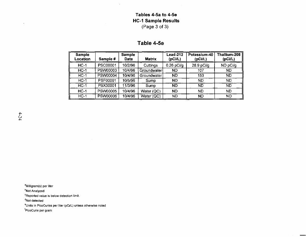
Tables 4-5a to 4-5eHC-1 Sample Results
(Page 3 of 3)
Table 4-5e
Sample Sample Lead-212 Potassium-40 Thallium-208Location Sample # Date Matrix (pCi/L) (pCi/L) (pCi/L)
HC-1 PSCOOO01 10/2/96 Cuttings 0.26 pCi/g 28.9 pCi/g NO pCi/gHC-1 PSWOOO03 10/4/96 Groundwater NO 107 NOHC-1 PSWOOO04 10/4/96 Groundwater NO 153 NOHC-1 PSFOOO01 10/5/96 Sump NO NO NOHC-1 PSXOOO01 11/3/96 Sump NO NO NOHC-1 PSWOOO05 10/4/96 Water (QC) NO NO NOHC-1 PSWOOO06 10/4/96 Water (QC) NO NO NO
aMilligram(s) per liter
bNot Analyzed
'Reported value is below detection limit.
dNot detected
'Uruts in PicoCuries per liter (pCi/L) unless otherwise noted
fPicoCurie per gram

5-1
5.0 Well HC-2 Summary of Operations
Well HC-2 was drilled to a depth of 397.15 m (1,303.0 ft) between October 5, 1996, and
October 15, 1996. A total of eight days was spent drilling and completing installation of this well.
Note that Figures 5-1 through 5-10 and Tables 5-1 through 5-5, cited in the following text, are
located at the end of this section.
Prior to mobilization, all drilling equipment was decontaminated at the on-site decontamination
pad using a combination of steam cleaning and high pressure washing. Decontaminated
equipment was subjected to a radiological screening prior to movement to the drill site.
A 30.48-cm (12.0-in.) surface conductor casing hole was drilled using air rotary reverse
circulation and a downhole percussion hammer to a depth of approximately 13.72 m (45.0 ft).
Due to its deviated condition, this hole was abandoned and cemented to the surface. A second
30.48-cm (12.0-in.) conductor hole was drilled approximately 3.05 m (10.0 ft) east of the first
location and successfully completed to a depth of 31.0 m (101.7 ft) bgs. A 21.91-cm (8.625-in.)
conductor casing was installed within the hole and cemented with Type II cement with 2 percent
calcium chloride additive from the TD of the hole to the ground surface.
The main hole was drilled to a depth of approximately 76.20 m (250.0 ft) bgs using a 20.32-cm
(8.0-in.) downhole percussion hammer assembly and air rotary reverse circulation drilling
techniques. Upon initial drilling of the main hole, the drilling subcontractor, Belik Drilling,
developed problems with the rig-mounted air compressor. Operations were suspended for
approximately one day to repair the air compressor. Repairs to the primary rig compressor could
not be completed, and a portable compressor was delivered to the site to supply air for drilling.
This compressor developed a severe oil leak after several hours of operation, and site operations
were again suspended for a period of five days between October 9, 1996, and October 14, 1996,
to allow for repair of the air compressors and other malfunctioning equipment associated with the
drilling.
On October 14, 1996, drilling operations resumed on the HC-2 drill site. Drilling proceeded at a
steady rate to a TD of 397.15 m (1,303.0 ft) bgs. Figure 5-1 provides a summary of drilling
parameters for the well. All figures and tables cited in the text are located at the end of this
section.

5-2
Well development using reverse circulation techniques was conducted on October 16, 1996,
following the drilling of the well. Upon completion of well development, drill pipe was pulled
from the well to allow for geophysical logging operations. The geophysical logging
subcontractor, Century Geophysical, was unable to reach the TD of the well due to an obstruction
in the borehole at a depth of 267.61 m (878.0 ft) bgs. The 20.32-cm (8.0-in.) drilling assembly
with a tricone button bit was tripped back in the hole to clear the obstruction and to clean the hole
to the TD of the well. Unstable, sloughing borehole conditions resulted in obstructions occurring
at depths of 231.65, 319.43, and 347.47 m (760.0, 1,048.0, and 1,140.0 ft) bgs. Two separate
attempts were required to clear and clean the borehole in preparation for geophysical logging.
Prior to logging, a sinker bar was run into the hole to establish whether any blockages had
developed. The sinker bar was unable to pass below a depth of 268.22 m (880.0 ft) bgs. It was
determined that geophysical logging of the available open borehole should be conducted. Century
Geophysical and DRI completed the logging of the well to the obstructed depth of 268.22 m
(880.0 ft) on October 18, 1996.
Intermediate (13.97-cm [5.5-in.]) casing was installed in the well to a depth of 291.69 m (957 ft)
bgs upon completion of geophysical logging operations. The intermediate casing needed to be
drilled down through obstructed portions of the borehole at approximately 268.22 m (880.0 ft).
The hole was then reentered using reverse circulation drilling techniques and an 11.75-cm
(4.625-in.) tricone bit to clean out the obstructed borehole below the final casing point. The hole
was cleaned and conditioned to a depth of 396.24 m (1,300.0 ft), at which point the drill pipe was
pulled from the hole in preparation for geophysical logging operations.
Geophysical logging was then conducted to a depth of 373.08 m (1,224.0 ft) bgs, at which point
the borehole was once again obstructed. The water level in the well at this time was noted at
343.77 m (1,127.85 ft) bgs. It was then determined by DRI that the well provided an interval of
36.57 m (120 ft) between 336.16 to 372.77 m (1,102.9 to 1,223.0 ft) of open borehole within the
saturated zone, which was determined to be sufficient to facilitate the planned scientific studies.
5.1 Well HC-2 GeologyWell HC-2 encountered principally a fractured, coarse-grained, biotite granite of Cretaceous age
throughout the drilled interval. An intrusive aplite dike was noted in the interval between 137.16
and 152.40 m (450 and 500 ft). Significant fault/fracture zones were apparent in the approximate
intervals between 134.11 to 152.40 m (440.0 to 500.0 ft), 176.78 to 192.02 m (580.0 to 630.0 ft),
252.98 to 257.56 m (830.0 to 845.0 ft), and 335.28 to 341.38 m (1,100.0 to 1,120.0 ft). A
detailed description of the lithologies encountered in the well is provided in Figure 5-2.

5-3
5.2 Well HC-2 Hydrology Several elements of hydrologic importance were monitored during and after the completion of the
well. During drilling operations, two monitoring parameters were consistently compared:
the volume of drilling fluids (water) injected to facilitate drilling and the recorded volumes of fluid
produced as discharge to the surface during the same time. Figure 5-3 illustrates the relationships
between injected drilling fluids and drilling fluid produced at the surface. In addition to these
volumetric measurements, all drilling fluids injected into the borehole were tagged with a tracer
solution of Lithium Bromide (LiBr). The concentration of this solution was monitored on a
regular basis to estimate groundwater production within the borehole. Table 5-1 illustrates LiBr
concentrations noted in produced fluids.
Water production from the well was minimal; monitoring data and water level recovery data
suggests the well was capable of producing approximately 0.75 to 1.0 gpm (2.8 to 3.8 L/min).
During several instances, the well was capable of intermittent production on the order of 3.0 to
5.0 gpm (11.4 to 18.9 L/min). These readings suggest production from perched water zones
along fault or fracture zones. These zones were of limited impact as their storage capacity was
exhausted, and their contribution to the well decreased.
Water-level monitoring was conducted during the construction of the well and continued after
completion using transducers set by DRI. Table 5-2 provides water levels obtained for the term
of IT involvement in PSA field work.
5.3 Well HC-2 Geophysical SurveysA suite of downhole geophysical surveys was run within the borehole upon completion of drilling
to the TD of 397.15 m (1,303.0 ft) after a phase of well development. Due to unstable borehole
conditions, geophysical logging was conducted in two separate phases. The first phase consisted
of logging by both Century and DRI to a depth of approximately 259.08 m (850.0 ft) bgs. Upon
completion of these logging runs, intermediate casing was installed in the well to a depth of
291.69 m (957.0 ft) bgs. After casing installation, the well was logged from a point below the
casing to the well’s accessible total depth of 373.08 m (1,224.0 ft) bgs. The portion of the
borehole from 259.08 to 291.69 m (850.0 to 957.0 ft) was not logged due to obstruction of the
borehole at 259.08 m (850.0 ft) and to the installation of intermediate casing to a depth of
291.69 m (850.0 ft) bgs.
Deviation surveys conducted within the casing and borehole indicate the borehole is deviated
2.7 degrees from vertical in a north-northeast direction. The deviation of the hole placed the

5-4
bottom of the hole 4.88 m (16.0 ft) north-northeast of the collar and resulted in a true vertical
depth of 369.97 m (1,213.81 ft) bgs.
Table 5-3 provides a summary of the geophysical logs run for the well. Additional specialized
logging was performed by DRI as part of their scientific work scope. Figures 5-4 to 5-7 provide
condensed illustrations of log traces for well HC-2.
5.4 Well HC-2 Radiologic MonitoringMonitoring of discharge effluent from drilling was conducted as specified in the Project Shoal
SSHASP (DOE/NV, 1996b) and the FMP for the Project Shoal Area Offsite Subproject
(DOE/NV, 1996c). Regular radiological monitoring of discharged drilling effluents, including
both fluids and solids, was conducted by Bechtel Nevada radiation control technicians. Samples
for further analysis were screened using handheld instruments at the time of collection. Effluents
were then further analyzed for tritium and other radionuculides using on-site laboratory
monitoring equipment. Tritium activities from fluid and swiped samples were recorded using a
Packard Liquid Scintillation instrument. Other radionuculides were analyzed using Canberra
gamma spectroscopy instrumentation.
Well HC-2 effluents were found to contain only natural background levels of tritium and other
radionuculides based on results of field monitoring. Figure 5-8 is a profile of tritium encountered
in fluids produced from the well.
5.5 Well HC-2 Well ConstructionFinal construction of Well HC-2 included the drilling of a 30.48-cm (12.0-in.) surface borehole to
a depth of 31.39 m (103 ft). Conductor casing comprised of 21.91-cm (8.625-in.) carbon steel
was installed in the 30.48-cm (12.0-in.) hole. Bow type centralizers were placed approximately
1.52 m (5.0 ft) from the bottom of the casing. Conductor casing was cemented to the surface
using Type II cement with 2 percent calcium chloride as an additive. An 30.32-cm (8.0-in.)
borehole was drilled to a TD of 397.15 m (1,303.0 ft) bgs beneath the conductor casing.
Intermediate, 13.97-cm (5.50-in.) carbon steel casing was installed in the completed borehole and
set at a depth of 291.08 m (955.0 ft) bgs. Intermediate casing was installed without centralizers
or cement baskets due to adverse borehole conditions; casing was then suspended on landing
straps secured to the surface conductor casing. Figure 5-9 provides a schematic view of the final
completion. The surface completion for the well head is illustrated in Figure 5-10.

5-5
5.6 Well HC-2 SamplingSamples for analytical analysis were collected from fluids and cuttings as specified in the
Field Instructions for Project Shoal Area Surface and Subsurface Investigation, Churchill
County, Nevada (IT, 1996) and the FMP for the Project Shoal Area Offsites Subproject
(DOE/NV, 1996c). The sample type and analytical results of these samples are shown in
Tables 5-4 and 5-5.

I!Logged By: Century Geophysics/DRI
:Drilling Co.: Beylik Drilling Services
~Drilling Method: Air Rotary/ Reverse Circulation
WOB(psi)
60 -20000 5000
IT CORPORATIONProject ShoalProject No. 764044.03.07.00.00
4000
Date Finished: 10/20/96
!Date Began:10/6/96
Air RPMPress(psi)
RotaryTorque
(psi)
20000
Water WaterInjection Production
(gpm) 12 0 1210100
Rate ofPenetration
(mlnlft)
o
Figure 5-1Summary of Well HC-2 Drilling Parameters
5-6 --'--'-.=:.=.=-:..:..::..:....:...::....:.=...:...::.:..::..::-='-.:..::.::.:.=..::.._-
GRANITE
lithDepth ! Depth ! Strata Rock(feet) I(meters!! Unit
I i
I
iHole No.:HC-2
ISurface Elevation:5347.12
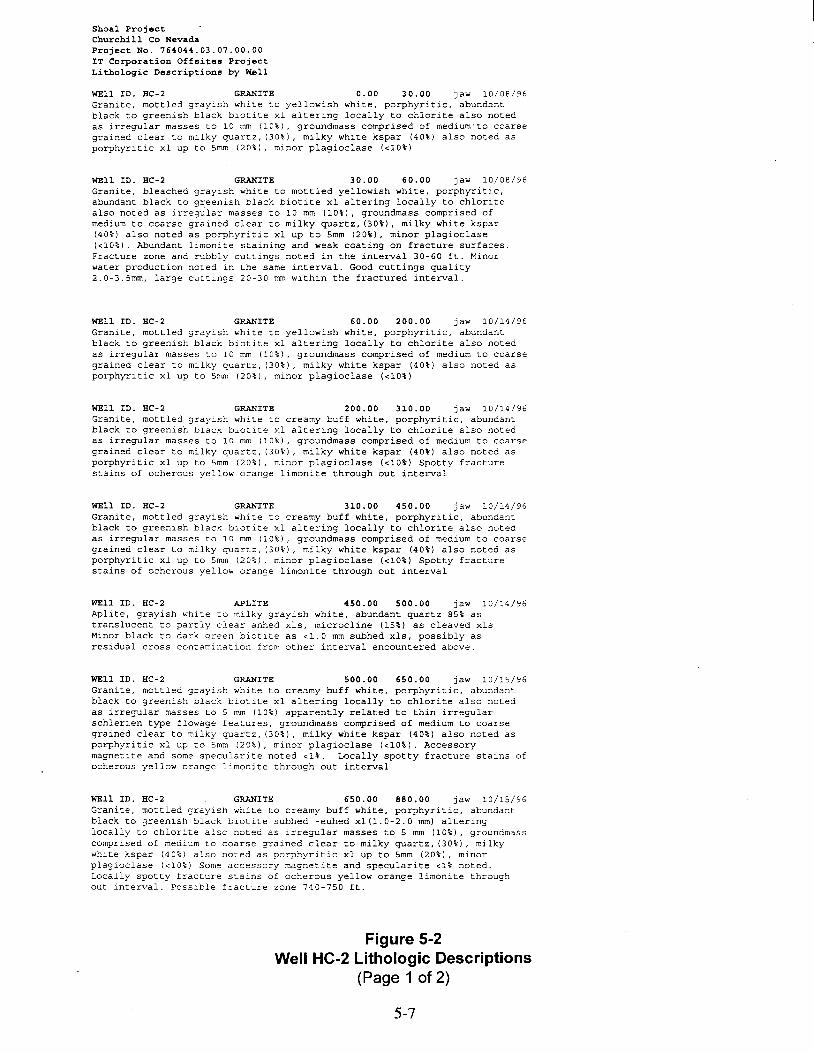
Shoal ProjectChurchill Co NevadaProject No. 764044.03.07.00.00IT Corporation Offsites ProjectLithologic Descriptions by Well
WEll ID. HC-2 GRANITE 0.00 30.00 jaw 10/08/96Granite. mottled grayish white to yellowish white, porphyritic, abundantblack to greenish black biotite xl altering locally to chlorite also notedas irregular masses to 10 mm (10%), groundmass comprised of medium·to coarsegrained clear to milky quartz, (30%), milky white kspar (40%) also noted asporphyritic xl up to 5mm (20%), minor plagioclase «10%)
WEll ID. HC-2 GRANITE 30.00 60.00 jaw 10/08/96Granite, bleached grayish white to mottled yellowish white, porphyritic,abundant black to greenish black biotite xl altering locally to chloritealso noted as irregular masses to 10 mm (10%), groundmass comprised ofmedium to coarse grained clear to milky quartz, (30%), milky white kspar(40%) also noted as porphyritic xl up to 5mm (20%), minor plagioclase«10%). Abundant limonite staining and weak coating on fracture surfaces.Fracture zone and rubbly cuttings noted in the interval 30-60 ft. Minorwater production noted in the same interval. Good cuttings quality2.0-3.5mm, large cuttings 20-30 mm within the fractured interval.
WEll ID. HC-2 GRANITE 60.00 200.00 jaw 10/14/96Granite, mottled grayish white to yellowish white, porphyritic, abundantblack to greenish black biotite xl altering locally to chlorite also notedas irregular masses to 10 mm (10%), groundmass comprised of medium to coarsegrained clear to milky quartz, (30%), milky white kspar (40%) also noted asporphyritic xl up to 5mm (20%), minor plagioclase «10%)
WEll ID. HC-2 GRANITE 200.00 310.00 jaw 10/14/96Granite, mottled grayish white to creamy buff white, porphyritic, abundantblack to greenish black biotite xl altering locally to chlorite also notedas irregular masses to 10 mm (10%), groundmass comprised of medium to coarsegrained clear to milky quartz, (30%), milky white kspar (40%) also noted asporphyritic xl up to 5mm (20%), minor plagioclase «10%) Spotty fracturestains of ocherous yellow orange limonite through out interval
WEll ID. HC-2 GRANITE 310.00 450.00 jaw 10/14/96Granite, mottled grayish white to creamy buff white, porphyritic, abundantblack to greenish black biotite xl altering locally to chlorite also notedas irregular masses to 10 mm (10%), groundmass comprised of medium to coarsegrained clear to milky quartz, (30%), milky white kspar (40%) also noted asporphyritic xl up to 5mm (20%), minor plagioclase «10%) Spotty fracturestains of ocherous yellow orange limonite through out interval
WEll ID. HC-2 APLITE 450.00 500.00 jaw 10/14/96Aplite, grayish white to milky grayish white, abundant quartz 85% astranslucent to partly clear anhed xls, microcline (15%) as cleaved xlsMinor black to dark green biotite as <1.0 mm subhed xls, possibly asresidual cross contamination from other interval encountered above.
WEll ID. HC-2 GRANITE 500.00 650.00 jaw 10/15/96Granite, mottled grayish white to creamy buff white, porphyritic, abundantblack to greenish black biotite xl altering locally to chlorite also notedas irregular masses to 5 mm (10%) apparently related to thin irregularschlerien type flowage features, groundmass comprised of medium to coarsegrained clear to milky quartz, (30%), milky white kspar (40%) also noted asporphyritic xl up to 5mm (20%), minor plagioclase «10%). Accessorymagnetite and some specularite noted <1%. Locally spotty fracture stains ofocherous yellow orange limonite through out interval
WEll ID. HC-2 GRANITE 650.00 880.00 jaw 10/15/96Granite, mottled grayish white to creamy buff white, porphyritic, abundantblack to greenish black biotite subhed -euhed xl(1.0-2.0 mm) alteringlocally to chlorite also noted as irregular masses to 5 mm (10%), groundmasscomprised of medium to coarse grained clear to milky quartz, (30%) I milkywhite kspar (40%) also noted as porphyritic xl up to 5mm (20%), minorplagioclase «10%) Some accessory magnetite and specularite <1% noted.Locally spotty fracture stains of ocherous yellow orange limonite throughout interval. Possible fracture zone 740-750 ft.
Figure 5-2Well HC-2 Lithologic Descriptions
(Page 1 of 2)
5-7
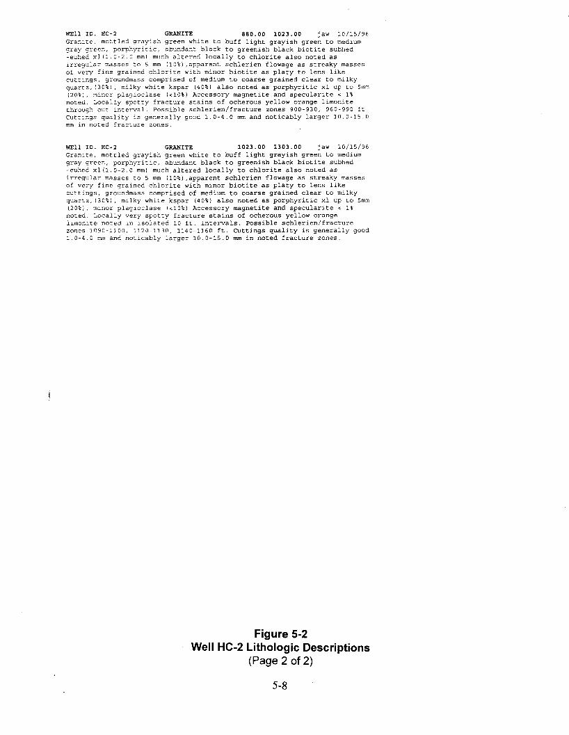
WEll ID. HC-2 GRANITE 880.00 1023.00 jaw 10/15/96Granite. mottled grayish green white to buff light grayish green to mediumgray green, porphyritic, abundant black to greenish black biotite subhed-euhed xlI1.0-2.0 mm) much a Lt e r-e d locally to chlorite also noted aslrregular masses to 5 mm 110%) ,apparent schlerien flowage as streaky massesof very fine grained chlo:,-ite with mino:,- biotite as platy to lens likecuttings, groundmass comprised of medium to coarse grained clear to milkyquartz, 130%), milky white kspar (40%) also noted as porphyritic xl up to 5mm(20%), minor plagioclase «10%) Accessory magnetite and specularite < 1%noted. Locally spotty fracture stains of ocherous yellow orange limonitethrough out interval. Possible schlerien/fracture zones 900-930, 960-990 ft.Cuttings quality is generally good 1.0-4.0 mm and noticably larger 10.0-15.0mm in noted fracture zones.
WEll ID. HC-2 GRANITE 1023.00 1303.00 jaw 10/15/96Granlte, mottled grayish green white to buff light grayish green to mediumgray green, porphyritic, abundant black to greenish black biotite subhed-euhed xl(1.0-2.0 mm) much altered locally to chlorite also noted asirregular masses to 5 mm (10%) ,apparent schlerien flowage as streaky massesof very fine grained chlorite with minor biotite as platy to lens likecuttings, groundmass comprised of medium to coarse grained clear to milkyquartz, (30%), milky white kspar (40%) also noted as porphyritic xl up to 5mm(20%), minor plagioclase 1<10%) Accessory magnetite and specularite < 1%noted. Locally very spotty fracture stains of ocherous yellow orangelimonite noted in isolated 10 ft. intervals. Possible schlerien/fracturezones 1090-1100, 1120-1130, 1140-1160 ft. Cuttings quality is generally good1.0-4.0 mm and noticably larger 10.0-15.0 mm in noted fracture zones.
Figure 5-2Well HC-2 Lithologic Descriptions
(Page 2 of 2)
5-8

IGeology and Water ProductionSummaryIHoleNo ·HC·2
'Surface Elevation:5347.12
!Depth
IDepth i Strata
IRock
(feet) (meters)I
Unit
I
, III I
Northing:162020B.30I lithology , RockI I Type
I
WaterLevel
o
IEasting:555447.BOWater Injection Rate
(gpm)
IDate Finished: 10/20/96Water Production Rate
(gpm)
15
:=--10.0
11S···········
'B.e',~B.O
:~
~o ."S.G"'·" ....
•
.......f2l~.':G.O~~:......;.., .... ,......... il
-M..... .rt8 , .
0.0
f················,··············l..+~:g: 6.0
I~of···············-+·········I~.....
····l······
u.u
0.0
0.0
"I'~~'
w..............!r--e,7&-~'='_"_=~;; ~ ,....... 11
··············f················,················,····[
00..............0.0 .
RR
··············f················;··········=-!-
·······f·········,·········p·~a .
·····-r···,·····Ju···,···
············r·
----------.-- --.. ···--1 ~.~
__8H --4.:,~g _ - .
0.0
0.0-00nn
~o '.•
~F~=:::::f1:'1.-:0-sSt ,........ .6:0
~60 • ~ .f················.·····I'!:·=.o--'·q,S············t f················:···········rg:?-.o&0 _ -
'4A. I~~ : , f , 2,,§,,2~•.6..··~··.5'·· ·······:·················:················~I
··············_·····~t·······:········~·····
...••.~•••..•: f...••......• ····,······~·········+11····
f·············,···············tn....6.0
f············;···············ln.6.0
./.50'f···············:········<..,~ir__·········:······
/. 05 5
0.0.0.0 _ .RR0.0.0.0.RR
f···············.··········,.2:'6;rlB ~6.0 •
gg
'Y-.. (9.0f···············:··············-"~.=-<··8cl}· .,.. , , -5,Qc:.:··············,···············:··············~1wt::?:7.0
6:0f··············;··········~·:z-::.ci-6·G-
~5:0, ; ~«u..:--- .
f.......•.•.... 7 r4~f:.6..... ~lO L ..~:~n -="'-:<'7.0 •
f ; ~.•......""l=·6.0... {.fQ..B..O, _..1.6.5 1 7.0 :
f··············;·····<..;.?"'-i·5:/·0.....~t8...........
f···············:·······~~·5.5,S .... ·····c···~ ~.
"6...0f···················A···~?'.o-6·G. . ,..
v ~ ~~1-------'---+ ; ~7'!.-6.G- ~=~=::==;_<>.![:~O·ly ~ ·~··········jl
......,~tR - f , '$"':[G.:~B..O: .
GRANITE
.- APL.iii····-
v v v v "'GRANiTE-vvvvvvvvvvvvvvvvv
~:v:v:v:vvvvvvvvvv
~v v v vvvvvvvv
:::::::1vvvvvvvvvvvvvvvvvvvvvvvvvvvvvvvvvvvvvvvvvvvvvvvvvvvvvvvvvvvvvvvvvvvvvvvvvvvvvvvvvvvvvvvvvvvvvv
vv"'vV",VIvvvvvvvvvvvvvvvvvvvvvvvvvvvv
r~v:v:v:vvvvvvvvvvvvvvvvvvvvvvvvvvvvvvvvvvvvvvvvvvvvvvvvvvvvvvvvvvv
f~~~~~~~,vVvvvvv~vvvvvvvvvv
~:~:~:]vvv~
:v:v:vv~vvvvvvvvvv
400
BOO
700
500
900
600
300
200
100
1000
1100
1200
Figure 5-3
Loggeq By: CenturyGeophysics/DRI IT CORPORATION
IDrilling Co.: BeylikDrilling Services Project Shoal
Drilling Method: Air Rotaryl Reverse Circulation _P'-'-'r0:Lj·4e::cct=.:..:.N.;.;o:..:....:7...:64'---'-=-044...:....:.;.c.::0c.::3.:..;.O:..:7..:..0::c0:..:.-=-OO-=---_.....J
HC-2 Fluid Injection versus Production Diagram5-9

Hole NO.:HC-2
Surface Elevalion:5347.12Depth I Depth : Strata Rock(feel) tmelers) Unit
I :, I
-;20 140 -i60 -j80.J
100 ~120 1140 1160 j180 -i200 1
220 ~240 .:
260 -j280 ~300 --:
320 ~340-j360 1380 -i400 j420 ~
440"';
460 jJ480 -I
l500 -j
520 -i540~560 j
580.J
600 -j620 1640 -]
660--1
680 -i700 ~
720~740 j760 -i
-;
780 -j
800 ~.,820 1840 1860 --;
880 -.:J-;900 1920 1940-1
960 -j980 "j
1000 --11020 -j1040-]
1060--1
1080 j1100 -i1120 -j1140 --11160 -j1180 -i1200 ~1220 11240 11260 -11280 -j
F UID lE L
Spectra Gamma RayUranium
(cps)1~
iLogge\! By: Century Geophysics/DRI IT CORPORATIONII Drilling Co.: Beylik Drilling Services • Project Shoal
.Drilling Method: Air Rotary/ Reverse Circulation Figure 5-4 Project No. 764044.03.07.00.00
HC-2 Geophysical Log Traces of Spectra Gamma Ray5-10

I
(
5=s- J) ..
)
iGeoloov and Geoohvsicat Log Summary i
2000~
.
<
Date Finished: 10/20/96
Date BeQan:10/6/96
I Neutron: (cps)
50010
v
Resistivity(ohmlm)
200
IEastino:555447.80
-:-
Caliper(inches)
o
Rock ! Water IType ' Level
I Northing: 1620208.30
! Hole NO.:HC-2
iSurface Elevation:5347.12i Depth i Depth : Strata I Rock lithology
(feet) Kmetersl Unit I I
I I I I I
iII
~I
t~~jI r v v
I I .VvV<1 ~vvvvvi j,"'",V",V "'","'vII 1020l ~vvvvv "'","'vII IVYV
VV ~
I l ~~~~~~~vvvv
~VVVV'i
I l.v v v tyvvyv...
i roaol r::::1","vvl
~~~~~~I rVvVvVV"'V
V iI 320 -Y"'",v",v
tvvvVJ~vvvvl VVIVY"" rvv
tv vr
v v1060 vvvi vv
vV'l! ~vv-tv v VI vv
VVI rvvvvvv~vvvv
tv» tyvyVyvvvvv r"'yVyIVYV vv
1080 rvvvvv. .....vv~vv.vv~ v v~Iv,,",," VV• vv
'~~jtv vvvvvvvvv ~vvj.v v vvv ~vvvv
1100 l IVYV vvr",vyvV
vvr v v
rtv v v vv~
1 vv VVjvvv vvI vv vv
340.JrVyVyv vv,! vvv ::::j1120 l rvv
~v v vvv vv~rVV v t:""Vv "'",vv
" v,,"vi
~~<v~I -Yvv,\\
i ~VvVvl ..... vvvvv r v v1140 l ~ v v ~
k~~~~IvvlI
J~~ij IV v VI
f"'V ~~~~~j1160 ~
vvvvvvv ~vVvV~vvvvv
v~v~~VVVI
(vvv ~vv.I vvtv~~~~ vvv
I vVvv
1I r v v JI vv
~vv v ~VVVVJ1180 I vv ~vv360-1vvv vV'i
~v>~~~vv
I VVjvvi
LY","'",vl vv "'"VV
rzoo>
~vvvvv toY","'vl
TVVl ~~~~~jC
VVVvvvvvv ~vvvvv rVv"'vvv
I ,VYV VVyvvvv ~vvI vv
!vv
~VVVVV! vv1220 -I
1~~~vvvv
I ~vv
I t:-""'vv",-1
VvVvl r~v~vJI
vvvvvvvv
t~~~~j1240l JVVVVvvvvv~
~vv
sec l~~1vv
~v~v~
,zeo j ~vvv
{VVVVV t~~~~,vv VV 'vvv
~~~:128J
t~::lvvvvv
fvvvvvvv
I v>~i 'O-O-j"00'
~vv~vv v vvvv vvrV V IfVvvv:v:~ vv
vvIVV~ vv.fVV VVI
Figure 5-5
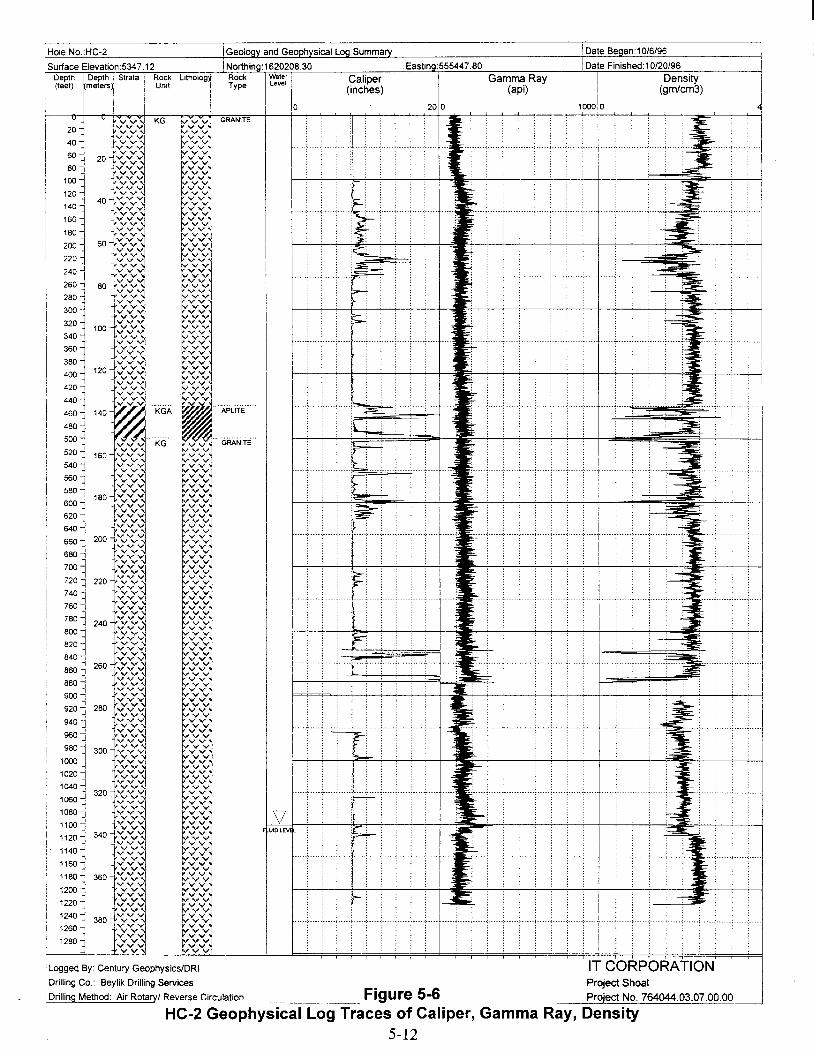
IGeology and Geophysical Log SummaryIiHole NO.:HC-2
!Surface Elevation:5347.12i Depth I Depth , Strata I Rock
i (feel) rmete~i I Unit
itholog"
II
INorthing:162020830Rock IWale, ,Type Level 10
Caliper(inches)
IEastlno:555447.80
200
Gamma Ray(api)
iDate Began' 10/6/96
Date Finished: 10/20/96
I DensityI (gmlcm3)
10000
i
~
-.
~:": ; : ; I
.4
~ : ; : .. , : ;.. ., ..+ .. ; ""=.;~=;.
1- .,:
b--.-
.,....
.-.~s::~
I
I·····:·····,······;····-!-····:·····;·····;·····,·····:·····f·····,·
1·····'····;·····;····+····;····;·····,·····;····-;····f·····
f··:····,·,·····I!·····, .. , ··f·····;·, ...! ....
f·····;·····:·····:·····;-..;~=,·····:·····;···!·····
br····'····,·····;·····I'·····,···,·····;····;···.,····! ,,;,: ; -; : :: : , : -f..·;······;·····,······;·····::0..····;······:·····,···1
~
F UID LEVEL
GRANITE
"'APLiTE'"
1260 -11280 1
iLogged By: Century Geophysics/DRI
,Drilling Co.: Beylik Drilling Services
,Drilling Method: Air Rotary/ Reverse Circulation ..__ Figure 5-6
IT CORPORATIONProject ShoalProject No. 764044.03.07.00.00
HC-2 Geophysical Log Traces of Caliper, Gamma Ray, Density5-12

I Hole No.:HC-2
I Surface ElevatJon:5347.12i Depth IDepth .. Strata Rock! (feel) Imelers~ UnJI
I I
t'thO"
I !I
iGeoloav and Geoohvsical Loa Summarv IDate Began:10/6/96 I
I Northina:1620208.30 Eastina:555447.80 IDate Finished: 10/20/96Rock Water Temperature PH I EC LiBrType Level
(F) (umos) (mgtl) I
101600
II
65 706 700 0 50i
1020
1040
1060
1080
1100
1120
1140
1160
1180
1200
1220
1240
1260
1280
1300
F UIDLEVl L
LoggeJ;l By: Century Geophysics/DRI
IDrilling Co.. Beyllk Drilling Services
Drilling Method: Air Rotary/ Reverse Circulation
5-13

IDate Finished: 10/20/96
Tritium in Fluids(pCilL)
Date Beaan: 10/6/96
-=
;
iEasting:555447.BO
"""' ; ; .:. ,....................... ··1<.
.......~".. ; ; .:. , j
~......;.7
r
....~
o
r-,..",."', : , : , .
~....
WaterLevel
GRANITE
Northina:16202DB.30·1 Lithology Rock
Type
v v v v ··-GRANITE'·vvvvvvvvvvvvvvvvvvvvv
r:::::::vvvvvvvvvvvvvvvvvvvvvvvvvvvvvvvvvvvvvvvvvvvvvvvvvvvvvvvvvvvvvvvvvvvvvvvvvvvvvvvvvvvvvvv
:«<1vvvvvvvvvvvvvvvvvvvvvvvvvvvvvvvvvvvvvvvvvv~vvvvvvvvvvvvvvvvvvvvvvv~vvvvvvv
....,vvvvv\vvvvvvv
vvvvvv\vvvvvvvvvvvvvvvvvvvvvvvvvvvvvvvvvvvvvvvvvvvvvvvvvvvvvvvv
:<V:<Ivvvvvvvvvvvvvvvvvvvvvvvvvvvvvvvvvv~vvvvvvvvvvvvvvvvv
vvv~vvvvvvvvvvvvvvvvvvvvvvvvvvvvvvvvvvvvvvvvvvvvvvvvvvvvvvvvvvvvvvvvvvvvvvvvvvvvvvvvvvvvvvvvvvvvvvvvvvvvvvvvvvvvvvvvvvvvvvvvvvvvvvvvvvvvvvvvvvvvvvvvvvvvvvvvvvvvvvvvvvvvvrv v vvvvvvvv
'vvvvvvvvvvvvvvv
iGeology and Tritium in Fluids
RockUnit
v
800
700
900
500
300
400
200
600
100
1000
1100
1200
Surface Elevation:5347.12Depth I Depth 1 Strata i(feet) I (meters) I I
Hole No.:HC-2
Logged By: Century GeophysicslDRI
Drilling Co.: Beylik Drilling Services
Drilling Method: Air Rotary/ Reverse Circulation HC-2 TritiumFigure 5-8 IT CORPORATION
C t t" 0" 0 "II" Project Shoaloncen ra Ions urmg n mg Project No. 764044.03.07.00.00
5-14
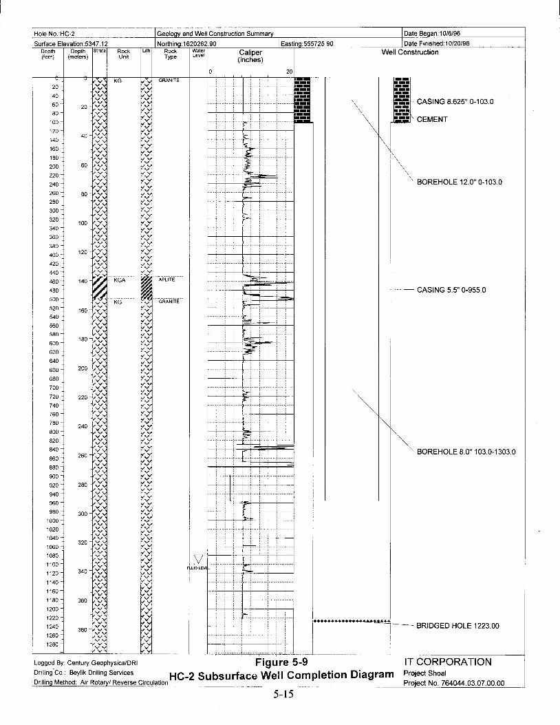
Hole NO.:HC-2 IGeology and Well Construction Summary IDate Began:10/6/96
Surface Elevation:5347.12 INorthina:1620262.90 IEastina:555725.90 IDate Finished:10/20/96Depth Depth Strata Rock Lith Rock Water Caliper Well Construction(feet) (meters) Unit Type Level
(inches)
0 20u u
vv... KG ....:;.. GRANITE ,- ~_-:--20 ,- ~_-:vv-, ....:.-;- --40 / ... ,,:.-;- ,-I60 20 vv... ~:.-;-
\~. CASING 8.625" 0-103.0
80 vv-, ,...:.-;- Ii:"'_vv... ,,:.-;- - =\ CEMENT100 vv-, v:'-;-
120 vv-, v:'-;-40 \--
140 -r. v:'-;- \160 vv, V../180 -r. V../
1'\ BOREHOLE 12.0"0-103.0
.r. V../200 60 .r. V../220 .r. v;'v240 .r. v;'v ,,;;;;
260 .r. v;'v ri-80 .r. v;'v --280 .r. v;'v
300 -r. v;'v.r: V;.V r-
320100 .r: V;.V
340 .r: ;.V360 .r: .·v380 .r, V:':V
400 120 .r, V:':V.r. vS
420 .r. v:':v440
~.Vv
'"'-~460 140 KGA . APLiTE'"
480 CASING 5.5" 0-955.0500 ~. KG '''GRAN!i'E''v:':v :>i---'520 160 <~ v:':v540 v':~ v:':v :~.r:560 »: v:':v ~580 vv~ .....v
~F-.180 V'v600 v.....~v.....~ V'v :'::;~
620 .....v ,.=0:v.....v640 .r: V'v660 200 .r, v:':v680 -r. v:':v700 c: v:':v
.r. v:':v :~
~720 220 .r. v:':v740
v:'v:':v
760 v:':vv v:':v780 .r: -,
240 »: v:':v800 -r: .....v .~
I~ BOREHOLE 8.0" 103.0-1303.0
820 .r: .....v840 /v ~
260 .r: ~ r860 Vy.r:880 .r; Vy900 .r. Vy920 280 vv, V~
940 .r, VV'v-r. VV'v
960 .r, VV'v980 300 .r. VV'v
1000 .r. v:':vv>
V:':V1020 Vy1040
v Vyv320 v
~1060 »:1080 .r: ....~
V-r; ....~1100 ....~vv... UID LEV l
"--~1120 340 vv... .........v1140 vv... .....v1160 .r: .....v
/v.,...:':V
1180 360 -r: ,...y1200 v':,,: ....:':v....y .;---1220 .r: ,...y ,++++++•••• +++1240 .r: - BRIDGED HOLE 1223.00
380 .r: ....y1260 vVv. ....y1280 v> ....y
vv
Logged By: Century Geophysics/DRI Figure 5-9 IT CORPORATIONDrilling'co. Beylik Drilling Services HC-2 Subsurface Well Completion Diagram Project Shoal
IDrillingMethod: Air Rotaryl Reverse Circulation .. ~----_..__._-- '.',. ------- Project No. 764044.03.07.00.00
5-15

Well Coordinates(State Planar NAD 27)N: 1620262.922E: 555725.939
Clamp/ Landing Plate
Well Pad
1.22 m x 1.22 m x 0.15 m(48 in x 48 in x 6 in)Reinforced with a 15.2-cm x 15.2-cm(6 in x 6 in) wire mat
I•1.22m
(48 in)
PlanView
•IProtective Casing
32.38-cm (12 3/4 in) od0.32-cm (.125 in) wall
Surface Casing
2191-cm (85/8 in) odOA8-cm (.188 in) wall
Intermediate Casing
13.97-cm (5 1/2 in) od12.70-cm (5.0 in) id
Data Logger Access Tube
3.81-cm (1 1/2 in) conduit
Shelter for Data Logger
60.96-cm (24 in) diameter pad
Icr\ ~ Lockable LidE .soco 0 32.38-cm (12 3/4 in)od Protective Casing0 NIri
Cap 13.97-cm (5 1/2 in) od ThreadedE .~UI"- 0
N Iri~
Intermediate Casing with 13.97-cm
E (5 1/2 in) od Threaded Couplingo .~
L() L()
,...: l"-to
Data Logger Access Tube0 •E .~ ·u
C") L()
Concrete PadC") N
M Iri0 •~ • ./f--
.::.... . ':.'.Ground Surface E ':':U I I ...... : ..... : ...Elevation o
.~ .', .:... ', .:.. ',0 I I
1629.81 m N 0 ..... :.......:«t.:: : ..... : ..... : ...Iri to I I ....:......:.....
(5347.12 ft).= ..... :..........
I :...... .... :.: ..........:......: ....: II)..\\Y IA\" , I A ," '"7" , , 1/\\\y {I\\
~~I~d
Surface Casing
Clamp/Landing Platef'r_ofile View
Figure 5-10HC-2 Well Head Completion Diagram
5-16

Table 5-1HC-2 Lithium Bromide Concentrations
Date Time Depth Sample Conc. Sample Temp
mm/dd/yy (24 hrs) (ft) (mg/L) (Co) Sample Source Analysis By10/15/96 1530 NA 25.3 20.3 accs (20 mg/L) J. Saavedra10/15/96 1530 NA 28.1 20.7 Water Truck (WT) J. Saavedra10/15/96 1545 1023 0.9 22.4 Discharge Line (DL) J. Saavedra10/15/96 1615 NA 33.5 21.9 WT J. Saavedra10/15/96 1615 1043 26.9 22.3 DL J. Saavedra10/15/96 1645 NA 30.9 23.7 WT J. Saavedra10/15/96 1745 NA 18.7 24.4 accs (20 mg/L) J. Saavedra10/15/96 1745 1063 23.3 23.9 DL J. Saavedra10/15/96 1800 NA 32.8 22.4 WT J. Saavedra10/15/96 1800 1083 20.6 22.4 DL J. Saavedra10/15/96 1900 NA 25.8 23.3 WT M. Flaugher10/15/96 1900 1095 26.3 23.5 DL M. Flaugher10/15/96 1935 NA 20.9 24.5 accs (20 mg/L) M. Flaugher10/15/96 2000 NA 26.3 22.7 WT M. Flaugher10/15/96 2000 1125 26.0 23.5 DL M. Flaugher10/15/96 2100 1150 24.4 24.3 DL R. Peterson10/15/96 2100 NA 27.6 21.2 WT R. Peterson10/15/96 2100 1150 NA NA DL R. Peterson10/15/96 2220 NA 20.7 24.6 accs (20 mg/L) R. Peterson10/15/96 2200 1180 23.8 25.7 WT R. Peterson10/15/96 2200 1180 25.2 25.5 DL R. Peterson10/15/96 2300 NA 28.6 22.8 WT R. Peterson10/15/96 2300 1190 29.1 23.5 DL R. Peterson10/15/96 2010 NA 20.9 24.7 occs (20 mg/L) R. Peterson10/15/96 2330 NA 32.9 24.5 WT M. Flaugher10/16/96 0000 NA 25.7 24.7 WT M. Flaugher10/16/96 0100 1235 21.2 25.1 DL M. Flaugher10/16/96 0155 1240 26.1 22.7 DL M. Flaugher10/16/96 0200 NA 21.7 24.2 WT M. Flaugher10/16/96 0230 NA 19.6 25.6 accs (20 mg/L) M. Flaugher10/16/96 0206 NA 24.5 24.4 WT M. Flaugher10/16/96 0205 1245 25.2 24.5 DL M. Flaugher10/16/96 0300 NA 27.3 21.3 WT M. Flaugher10/16/96 0305 1260 25.0 24.1 DL M. Flaugher10/16/96 0405 NA 22.6 25.3 WT M. Flaugher10/16/96 0405 NA 19.3 25.9 occs (20 mg/L) M. Flaugher10/16/96 0405 1270 22.2 25.3 DL M. Flaugher10/16/96 0505 NA 23.2 25.3 WT M. Flaugher10/16/96 0505 1290 24.0 24.9 DL M. Flaugher10/16/96 0610 NA 23.9 24.6 WT M. Flaugher10/16/96 0610 1300 27.5 24.5 DL M. Flaugher10/16/96 0615 NA 22.8 25.2 accs (20 mg/L) M. Flaugher10/16/96 0622 NA 29.3 23.6 WT M. Flaugher10/16/96 0622 1300 28.5 23.9 DL M. Flaugher10/16/96 0637 NA 27.6 24.5 WT J. Saavedra10/16/96 0637 1300 28.5 24.7 DL J. Saavedra10/16/96 0652 NA 30.5 23.1 WT J. Saavedra10/16/96 0744 NA 22.4 24.2 accs (20 mg/L) J. Saavedra10/16/96 0652 1300 28.9 25.0 DL J. Saavedra10/16/96 0800 NA 27.9 25.6 WT J. Saavedra10/16/96 0800 1300 25.2 25.5 DL J. Saavedra10/16/96 0945 NA 29.8 23.4 WT J. Saavedra10/16/96 1105 1300 34.6 23.8 DL J. Saavedra
5-17
I
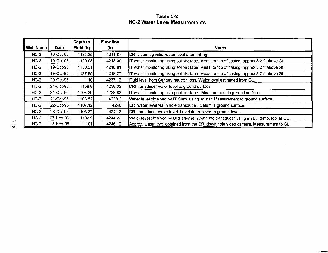
VlI......
00
Table 5-2HC-2 Water Level Measurements
Depth to Elevation
Well Name Date Fluid (ft) (ft) Notes
HC-2 19-0ct-96 1135.25 4211.87 DRI video log initial water level after drilling.
HC-2 19-0ct-96 1129.03 4218.09 IT water monitoring using solinist tape. Meas. to top of casing, approx 3.2 ft above GL
HC-2 19-0ct-96 1130.31 4216.81 IT water monitoring using solinist tape. Meas. to top of casing, approx 3.2 ft above GL
HC-2 19-0ct-96 1127.85 4219.27 IT water monitoring using solinist tape. Meas. to top of casing, approx 3.2 ft above GL
HC-2 20-0ct-96 1110 4237.12 Fluid level from Century neutron logs. Water level estimated from GL.
HC-2 21-0ct-96 1108.8 4238.32 DRI transducer water level to ground surface.
HC-2 21-0ct-96 1108.29 4238.83 IT water monitoring using solinist tape. Measurement to ground surface.
HC-2 21-0ct-96 1108.52 4238.6 Water level obtained by IT Corp. using solinst. Measurement to ground surface.
HC-2 22-0ct-96 1107.12 4240 DRI water level via in hole transducer. Datum is ground surface.
HC-2 23-0ct-96 1105.82 4241.3 DRI transducer water level. Level determined to ground level.
HC-2 07-Nov-96 1102.9 4244.22 Water level obtained by DRI after removing the transducer using an EC temp. tool at GL.
HC-2 13-Nov-96 1101 4246.12 Approx. water level obtained from the DRI down hole video camera. Measurement to GL.

Table 5-3HC-2 List of Geophysical Logs
Geophysical Date Log Top Log Bottom Logging
Well Name Log Logged (ft) (ft) Company
HC-2 3-Arm Caliper 10/18/96 0.00 878.60 Century Geophysical
HC-2 3-Arm Caliper 10/19/96 897.70 1223.00 Century Geophysical
HC-2 Density/Resistivity/Neutron/Neutron Porosity 10/18/96 0.00 880.50 Century Geophysical
HC-2 Density/Resistivity/Neutron/Neutron Porosity 10/19/96 881.80 1224.00 Century Geophysical
HC-2 Deviation - magnetic 10/16/96 0.00 876.00 Century Geophysical
HC-2 Deviation - gyroscopic 10/19/96 0.00 1214.30 Century Geophysical
HC-2 Spectra Gamma Ray (K, U, Th) 10/18/96 0.00 879.50 Century Geophysical
HC-2 Spectra Gamma Ray (K, U, Th) 10/19/96 901.50 1223.30 Century Geophysical
HC-2 Temperature 10/19/96 892.10 1225.80 Century Geophysical
HC-2 Acoustic Borehole Televiewer 10/20/96 1110.86 1222.82 Century GeophysicalHC-2 Acoustic Borehole Televiewer 10/20/96 1110.64 1222.58 Century GeophysicalHC-2 Chemtool 9/21/96 1110.00 1224.00 DRIHC-2 Chemtool 11/14/96 1106.00 1225.00 DRIHC-2 Downhole Video Camera 10/18/96 882.00 0.00 DRI
Note: Calibrations and repeat sections were performed per contract specifications.
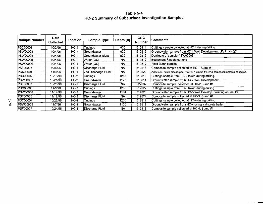
VIINo
Table 5-4HC-2 Summary of Subsurface Investigation Samples
.
Sample NumberDate
Location Sample Type Depth (ft)cac
CommentsCollected Number
PSCOOO01 10/2/96 HC-1 Cuttings 930 519811 Cuttings sample collected at HC-1 during drilling.
PSWOOO03 10/4/96 HC-1 Groundwater 920 519812 Groundwater sample from HC-1 Well Development...Full Lab QC
PSWOOO04 10/4/96 HC-1 Groundwater (dup) 920 519812 Duplicate of sample PSWOOO03
PSWOOO05 10/4/96 HC-1 Water (QC) NA 519812 Equipment Rinsate sample
PSWOOO06 10/4/96 HC-1 Water (QC) NA 519812 Field Blank sample
PSFOOO01 10/5/96 HC-1 Discharge Fluid NA 519816 Composite sample collected at HC-1 Sump #1
PCXOOO01 11/3/96 HC-1 2nd Discharge Fluid NA 519820 Additional fluidsdischarged into HC-1 Sump#1, 2nd composite sample collected.
PSCOOO02 10116/96 HC-2 Cuttings 1253 519813 Cuttings sample from HC-2 taken during drilling.
PSWOOO07 10/21/96 HC-2 Groundwater 1173 519814 Groundwater sample from HC-2 Well Development.
PSFOOO03 10/20/96 HC-2 Discharge Fluid NA 522037 Composite sample collected at HC-2 Sump #1.
PSCOOO03 11/5/96 HC-3 Cuttings 1255 519822 Cuttings sample from HC-3 taken during drilling.
PSWOOO08 11/14/96 HC-3 Groundwater 1104 519823 Groundwater sample from HC-3 Well Develop. Waiting on results.
PSFOOO05 11/12/96 HC-3 Discharge Fluid NA 519824 Composite sample collected at HC-3, Sump #1.
PSCOOO04 10/23/96 HC-4 Cuttings 1250 519817 Cuttings sample collected at HC-4 during drilling.
PSWOOO09 11/7/96 HC-4 Groundwater 1130 519819 Groundwater sample from HC-4 using a discrete bailer.
PSFOOO07 10/24/96 HC-4 Discharge Fluid NA 519818 Composite sample collected at HC-4, Sump #1

VlItv.......
Table 5-5a to 5-5fHC-2 Sample Results
(Page 1 of 3)
Table 5-5a
I Sample Sample Aluminum Antimony Arsenic Barium Beryllium Boron Cadmium Calcium Chromium
I Location Sample # Date Matrix (mg/L)8 (mg/L) (mg/L) (mg/L) (mg/L) (mg/L) (mg/L) (mg/L) (mg/L)
HC-2 PSCOOO02 10/16/96 Cuttings N/Ab N/A N/A N/A N/A N/A N/A N/A N/AHC-2 PSWOOO07 10/21/96 Groundwater N/A N/A N/A N/A N/A N/A N/A N/A N/AHC-2 PSFOOO03 10/20/96 Sump N/A N/A 0.0621 0.0556 N/A N/A 0.003 (NDt N/A 0.0044 (ND)
Table 5-5b
Sample Sample Cobalt Copper Iron Lead Lithium Magnesium Manganese Mercury MolybdenumLocation Sample # Date Matrix (mg/L) (mg/L) (mg/L) (mg/L) (mg/L) (mg/L) (mg/L) (mg/L) (mg/L)
HC-2 PSCOOO02 10/16/96 Cuttings N/A N/A N/A N/A N/A N/A N/A N/A N/AHC-2 PSWOOO07 10/21/96 Groundwater N/A N/A N/A N/A N/A N/A N/A N/A N/AHC-2 PSFOOO03 10/20/96 Sump N/A N/A N/A 0.0074 N/A N/A N/A 0.00025 N/A
aMilligram(s) per liter
bNot analyzed
CReportedvalue is below detection limit
dUnits in picoCuries per liter (pCi/L) unless otherwise noted.
·PicoCuries per gram
fNot detected
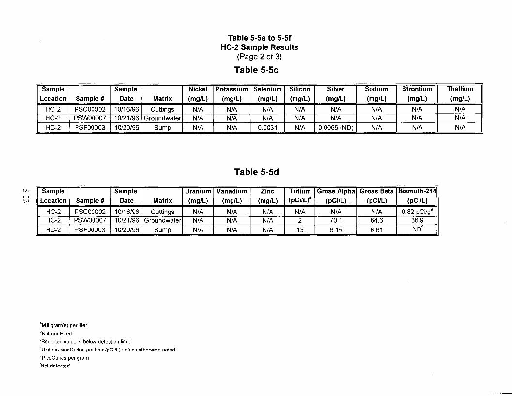
VIItvtv
Table 5-5a to 5-5fHC-2 Sample Results
(Page 2 of 3)
Table 5-5c
Sample Sample Nickel Potassium Selenium Silicon Silver Sodium Strontium Thallium
Location Sample # Date Matrix (mg/L) (mg/L) (mg/L) (mg/L) (mg/L) (mg/L) (mg/L) (mg/L)
HC-2 PSCOOO02 10/16/96 Cuttings N/A N/A N/A N/A N/A N/A N/A N/AHC-2 PSWOOO07 10/21/96 Groundwater N/A N/A N/A N/A N/A N/A N/A N/A
HC-2 PSFOOO03 10/20/96 Sump N/A N/A 0.0031 N/A 0.0066 (ND) N/A N/A N/A
Table 5-5d
Sample Sample Uranium Vanadium Zinc Tritium Gross Alpha Gross Beta Bismuth-214
Location Sample # Date Matrix (mg/L) (mg/L) (mg/L) (pCi/L)d (pCi/L) (pCi/L) (pCi/L)
HC-2 PSCOOO02 10/16/96 Cuttings N/A N/A N/A N/A N/A N/A 0.82 pCi/ge
HC-2 PSWOOO07 10/21/96 Groundwater N/A N/A N/A 2 70.1 64.6 36.9
HC-2 PSFOOO03 10/20/96 Sump N/A N/A N/A 13 6.15 6.61 NDT
aMilligram(s) per liter
bNot analyzed
'Reported value is below detection limit
dUnits in picoCuries per liter (pCi/L) unless otherwise noted.
ePicoCuries per gram
'Not detected
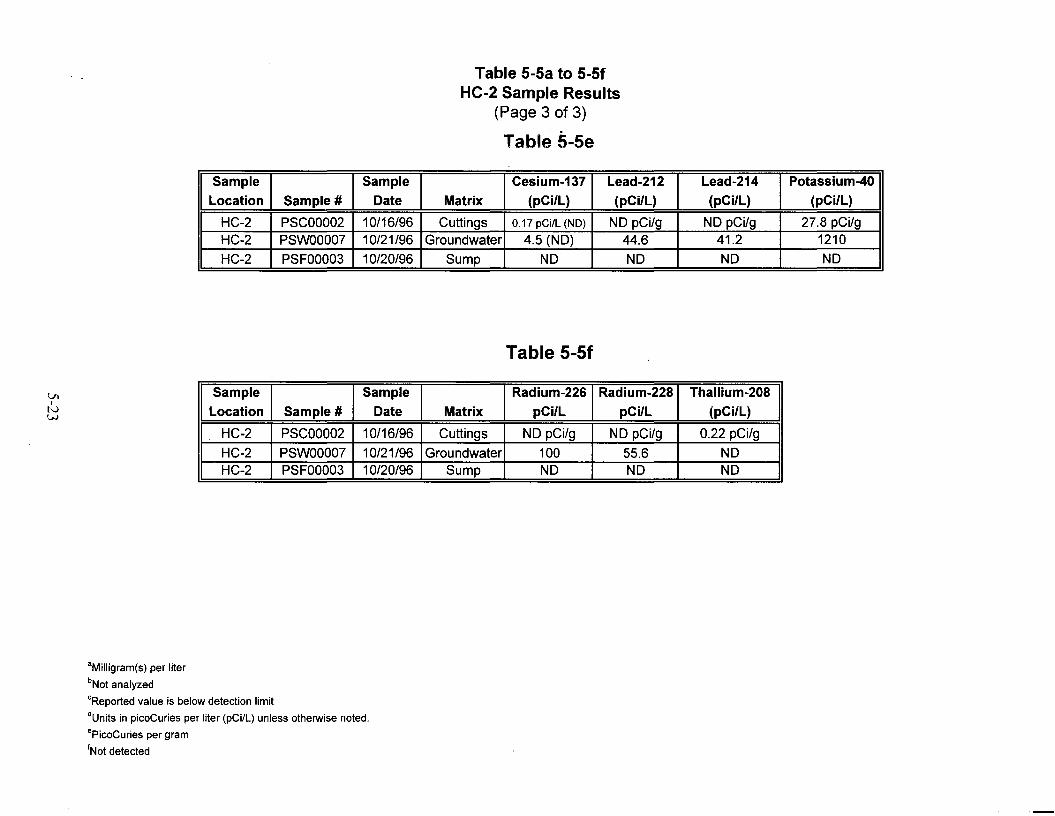
Table 5-5a to 5-5fHC-2 Sample Results
(Page 3 of 3)
Table 5-5e
Sample Sample Cesium-137 Lead-212 Lead-214 Potassium-40
Location Sample # Date Matrix (pCi/L) (pCi/L) (pCi/L) (pCi/L)
HC-2 PSCOOO02 10/16/96 Cuttings 0.17 pCilL (NO) NO pCi/g NO pCi/g 27.8 pCi/gHC-2 PSWOOO07 10/21/96 Groundwater 4.5 (NO) 44.6 41.2 1210
HC-2 PSFOOO03 10/20/96 Sump NO NO NO NO
Table 5-5f
Sample Sample Radium-226 Radium-22S Thallium-20S
Location Sample # Date Matrix pCi/L pCilL (pCi/L)
HC-2 PSCOOO02 10/16/96 Cuttings NO pCi/g NO pCi/g 0.22 pCi/g
HC-2 PSWOOO07 10/21/96 Groundwater 100 55.6 NOHC-2 PSFOOO03 10/20/96 Sump NO NO NO
'Milligram(s) per liter
bNot analyzed
'Reported value is below detection limit
dUnits in picoCuries per liter (pCilL) unless otherwise noted.
·PicoCuries per gram
INot detected

This page intentionally left blank

6-1
6.0 Well HC-3 Summary of Operations
Well HC-3 was drilled to a depth of 397.15 m (1,303.0 ft), between November 3, 1996, and
November 10, 1996. Eight days were spent drilling and completing the installation of this well.
Note that the Figures 6-1 through 6-9 and Tables 6-1 through 6-5, cited in the following text, are
located at the end of this section.
Prior to mobilization, all drilling equipment was decontaminated at the on-site decontamination
pad using a combination of steam cleaning and high pressure washing. Decontaminated
equipment was subjected to radiologic screening prior to mobilization to the drill site.
A 30.48-cm (12.0-in.) hole for the surface conductor was drilled using reverse air rotary reverse
circulation techniques and a downhole percussion hammer to a depth of 31.39 m (103.0 ft) bgs. A
21.91-cm (8.625-in.) carbon steel casing was installed in this hole and cemented to the surface
using Type II cement with 2 percent calcium chloride additive.
The main hole was drilled from below the casing point to a TD of 397.15 m (1,303.0 ft) bgs using
a 20.32-cm (8.0-in.) downhole percussion hammer and air rotary reverse circulation techniques.
Drilling progressed smoothly during the advance of the main hole. Some short delays resulted
from leaks/washouts of the discharge hose and cyclone; repairs were made quickly; and drilling
resumed. Drilling parameters for the well are provided in Figure 6-1. All figures and tables cited
in the text are located at the end of this section.
Upon completion of drilling operations, the well was circulated and developed for a period of
several hours. No fill was noted after completion of these operations, and the drill pipe was
tripped out of the hole on November 11, 1996, in anticipation of geophysical logging.
Geophysical logging commenced early on November 11, 1996. The first log run by DRI
encountered a bridge/obstruction at a depth at 165.81 m (544.0 ft) bgs. DRI removed the
wireline from the hole, and the bridge was removed with a sinker bar. DRI reentered the borehole
and resumed logging. A second borehole obstruction was encountered at a depth of 362.71 m
(1,190.0 ft) bgs. Several unsuccessful attempts were made to remove the obstruction using a
sinker bar. Beylik tripped back into the hole with a 20.0-cm (7.875-in.) percussion hammer bit to
clear the obstruction. Circulation was established at 304.8 m (1,000 ft) bgs. Severe sloughing of
the borehole was experienced in the interval between 329.18 and 335.28 m (1,080.0 and

6-2
1,100.0 ft) bgs, resulting in poor circulation and plugging of the drill bit. The drilling assembly
was tripped from the hole on November 11, 1996, and converted to conventional/direct
circulation. In order to facilitate conventional circulation, a second air compressor was placed on
site. Initial, direct circulation was established at a depth of 1,080 ft (329.81 m) using a mixture of
fresh water and foam. The well was then circulated and cleaned to TD of 397.15 m (1,303.0 ft)
bgs. Upon cleaning/circulating the borehole for a short period, the drill pipe was pulled back to a
depth of 365.75 m (1,200.0 ft) bgs to check for sloughing in the well.
The drilling assembly was lowered into the well to the TD of 397.15 m (1,303 ft) bgs, and
attempts to regain circulation were made without success. The drilling assembly was then tripped
out to a depth of 377.95 m (1,240.0 ft) bgs to make additional attempts to regain circulation.
After several attempts using foam and fresh water met with limited success, the drilling
subcontractor ran out of foam additive for the drilling fluids. Continued efforts to circulate using
only fresh water proved unsuccessful. Sloughing hole conditions resulted in the additional loss of
hole to a depth of 370.33 m (1,215 ft) bgs. It was determined that the drilling assembly be pulled
from the hole and intermediate casing be set to isolate sloughing portions of the hole.
On November 8, 1996, prior to setting intermediate casing, Century Geophysical completed a
suite of geophysical logs within the unsaturated portions of the borehole to a depth of 311.81 m
(1,023.0 ft) where a bridge prevented further logging.
Intermediate 13.97-cm (5.5-in.) carbon steel casing was set to a depth of 333.57 m (1,094.4 ft)
bgs after completing the unsaturated logging suite. Water level at the time the casing was set was
recorded at a depth of 330.10 m (1,083.0 ft). Upon setting of intermediate casing, a sinker bar
was run on the sand line to determine the TD of the well. The resulting measurement indicated
the well was bridged at a depth of 338.33 m (1,110.0 ft) bgs.
The hole was reentered on November 8, 1996, with a 11.75-cm (4.625-in.) tricone button bit
using a reverse circulation drilling assembly to attempt to clean out the well to TD. Several
attempts to clean and circulate to depths below the casing resulted in further sloughing of the
borehole and several plugged drill strings and bits. Clean out operations were conducted to a
depth of 384.05 m (1,260.0 ft) bgs, at which time it was determined to accept the depth of the
well as the TD. The drill pipe was pulled from the well, and Century Geophysical attempted to
log to the TD of the well when they encountered a bridge at a depth of 347.78 m (1,141.0 ft) bgs.
This depth was considered too shallow to allow access to saturated portions of the borehole.
Several attempts were made to clear the bridge using a sinker bar on a sand line with no
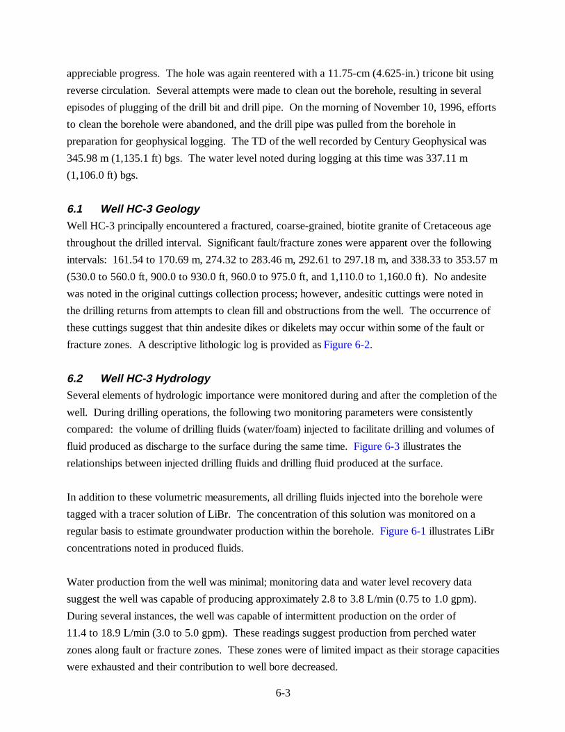
6-3
appreciable progress. The hole was again reentered with a 11.75-cm (4.625-in.) tricone bit using
reverse circulation. Several attempts were made to clean out the borehole, resulting in several
episodes of plugging of the drill bit and drill pipe. On the morning of November 10, 1996, efforts
to clean the borehole were abandoned, and the drill pipe was pulled from the borehole in
preparation for geophysical logging. The TD of the well recorded by Century Geophysical was
345.98 m (1,135.1 ft) bgs. The water level noted during logging at this time was 337.11 m
(1,106.0 ft) bgs.
6.1 Well HC-3 GeologyWell HC-3 principally encountered a fractured, coarse-grained, biotite granite of Cretaceous age
throughout the drilled interval. Significant fault/fracture zones were apparent over the following
intervals: 161.54 to 170.69 m, 274.32 to 283.46 m, 292.61 to 297.18 m, and 338.33 to 353.57 m
(530.0 to 560.0 ft, 900.0 to 930.0 ft, 960.0 to 975.0 ft, and 1,110.0 to 1,160.0 ft). No andesite
was noted in the original cuttings collection process; however, andesitic cuttings were noted in
the drilling returns from attempts to clean fill and obstructions from the well. The occurrence of
these cuttings suggest that thin andesite dikes or dikelets may occur within some of the fault or
fracture zones. A descriptive lithologic log is provided as Figure 6-2.
6.2 Well HC-3 Hydrology Several elements of hydrologic importance were monitored during and after the completion of the
well. During drilling operations, the following two monitoring parameters were consistently
compared: the volume of drilling fluids (water/foam) injected to facilitate drilling and volumes of
fluid produced as discharge to the surface during the same time. Figure 6-3 illustrates the
relationships between injected drilling fluids and drilling fluid produced at the surface.
In addition to these volumetric measurements, all drilling fluids injected into the borehole were
tagged with a tracer solution of LiBr. The concentration of this solution was monitored on a
regular basis to estimate groundwater production within the borehole. Figure 6-1 illustrates LiBr
concentrations noted in produced fluids.
Water production from the well was minimal; monitoring data and water level recovery data
suggest the well was capable of producing approximately 2.8 to 3.8 L/min (0.75 to 1.0 gpm).
During several instances, the well was capable of intermittent production on the order of
11.4 to 18.9 L/min (3.0 to 5.0 gpm). These readings suggest production from perched water
zones along fault or fracture zones. These zones were of limited impact as their storage capacities
were exhausted and their contribution to well bore decreased.

6-4
Water-level monitoring was conducted during the construction of the well and continued after
completion using transducers set by DRI. Table 6-2 provides water levels obtained for the term
of IT involvement in PSA field work.
6.3 Well HC-3 Geophysical SurveysUpon completion of drilling to the TD of 397.15 m (1,303.0 ft) and after a session of well
development, a suite of downhole geophysical surveys was run within the borehole. Due to
unstable borehole conditions geophysical logging was conducted in two phases. The first phase
consisted of logging by Century Geophysical and DRI to a depth of approximately 311.81 m
(1,023.0 ft) bgs. Upon completion of these logging runs, intermediate casing was installed in the
well to a depth of 333.57 m (1,094.40 ft) bgs. After casing installation, the well was logged from
below the casing point to the accessible TD of the well of 345.98 m (1,135.1 ft) bgs. That
portion of the borehole from 311.81 to 333.57 m (1,023.0 to 1,094.4 ft) bgs was not available for
geophysical logging due to unstable borehole conditions and the resulting installation of
intermediate casing.
Geophysical logs specified for the saturated portion of the borehole were not conducted due to
the slow recovery of water levels in the well and the short interval of open borehole below the
casing point.
Deviation surveys conducted within the casing and borehole indicate the borehole was deviated
18.1 degrees from vertical in a west-southwest direction. The deviation of the hole placed the
bottom of the hole 40.08 m (131.5 ft) west-southwest of the collar and resulted in a true vertical
depth of 304.89 m (1,000.30 ft) bgs.
Table 6-3 provides a summary of the geophysical logs run for the well and the corresponding
logged intervals. Additional specialized logging was performed by DRI as part of their scientific
work scope. Figures 6-4 to 6-6 provide condensed illustrations of log traces for Well HC-3.
6.4 Well HC-3 Radiologic MonitoringMonitoring of discharge effluent from drilling was conducted as specified in the Project Shoal
SSHASP (DOE/NV, 1996b) and the FMP for the Project Shoal Area Offsite Subproject
(DOE/NV, 1996c). Regular radiological monitoring of discharged drilling effluents, including
both fluids and solids, was conducted by Bechtel Nevada radiation control technicians.

6-5
Samples for further on-site lab analysis were screened using handheld instruments at the time of
sample collection. Effluents were then analyzed for tritium and other radionuclides using on-site
laboratory monitoring equipment. Tritium activities from fluid and swiped samples were recorded
using a Packard Liquid Scintillation instrument. Other radionuculides were analyzed using
Canberra gamma spectroscopy instrumentation.
Well HC-3 drilling effluents were found to contain only natural background levels of tritium and
other radionuculides based on results of field monitoring. Figure 6-7 provides a profile of tritium
encountered from fluids generated during drilling.
6.5 Well HC-3 Well ConstructionConstruction of Well HC-3 included the drilling of a 30.48-cm (12.0-in.) surface borehole to a
depth of 31.39 m (103.0 ft). Conductor casing comprised of 21.91-cm (8.625-in.) carbon steel
was installed in the 30.48-cm (12-in.) hole. Bow-type centralizers were placed approximately
1.52 m (5.0 ft) from the bottom of the casing and then centered at the surface. Conductor casing
was cemented to the surface using Type II neat cement with 2 percent calcium chloride as an
additive to aid curing time. A 20.32-cm (8.0-in.) borehole was drilled to a TD of 397.15 m
(1,303.0 ft) bgs from beneath the conductor casing.
Intermediate 13.97-cm (5.50-in.) carbon steel casing was installed in the completed borehole and
set at a depth of 333.57 m (1,094.4 ft) bgs. Intermediate casing was installed without specified
centralizers or cement baskets due to adverse borehole conditions. Intermediate casing was
suspended on landing straps secured to the surface conductor casing. Figure 6-8 provides a
schematic view of the final completion, and the surface completion for the well head is illustrated
in Figure 6-9.

6-6
6.6 Well HC-3 SamplingSamples for analytical analysis were collected from fluids and cuttings as specified in the Field
Instructions for Project Shoal Area Surface and Subsurface Investigation, Churchill County,
Nevada (IT, 1996) and the FMP for the Project Shoal Area Offsites Subproject
(DOE/NV, 1996c). The sample type and analytical results of these samples are shown in
Tables 6-4 and 6-5.

IDHDEPTH: 1303.00
I! Geology and Drilling Parameters
5000
WOS(psi)
RotaryTorque
(psi)
Water Water
'"I~r ,fod"diOORate of
Penetration(minlft)
o
,.\ , ; ; .
Rock WaterType Level
I Lith
Hole NO.:HC-3
Surface Elevation:5081.52Depth I Depth ! Strata Rock(feet) (meters) Unit
i I
I
iII . v v--: KGI., Yvvvv~I Yvvll {..Vv"'v1
j • v v ~20"" v v'VV'
I -IV" V V·vv
100! Yvvyv.,
l -v v ~1rvv~ <01'¥""JJ,
-v v v'vv
-VVVtvvvvv
200J ~ v v60-vVV
W¥lrvv
] -y v v-t.-v",v",iVY
i 80-YVVtvv
1 -Yvv
300 --1,;",vyvvJ
1 +:"':VI100 -" v V
1I tvvl -j"vv
~vv
lvv
J...vvvv l1
120+:V:V1400 -1 Jo/ V v
l rvvYVV
~ -r:v:v1I
~140 -+'VVVV~
t v vvvyvv
500J ~vvvv1
160tVvVvjj ,:v:v~j -Y v v'I vv 1vVV
"'VV'
600 J 180...Yvvvv,VVVjI ~vv
~ vvvi "lV'Vvvv
~iVV"
200-VvVv~i~vv
1 1 v v ~vvv-v v700 --1 .... vvv¥¥¥:I 2204 VV
yvvyVVvv~vvvv
";VV"l.V V v~
800 ~240~""VvVVj
JVVvVVJ J V V
I ?o"vvl
I -'vv 1vvv
l zso1:7:7:900~
","vV'~vv
yvvvvvvv
l 280 i-vvvv}vv
j vv}vvvv
I "vvJ vvv
1000 ~300i,..v",v.....
JVVvvv'vv1.-vv
j Jvvvvv
I 320 -{.VvVvJ-t JVV
J vvvJV'V
! tv:",:1100 II 340+
vvvv
.~ "r:""-:v.... vv
t:v:v
~
360 -YVVV~l1200 j tv"'","'..-yvv
i tvvvvIVV
I 380-VVVi -J...vvvvJ tvv
~vvI ~ v vJ -vvv
IT CORPORATIONProject ShoalProiect No. 764044.03.07.00.00
Figure 6-1Summary of Well HC-3 Drilling Parameters__. ~ . . ._~~~~===~=_-l
Logged By: Century GeophysicslDRI
Drilling Co.: Beylik DrillingServices
Drilling Method: Air Rotaryl Reverse Circulation
6-7
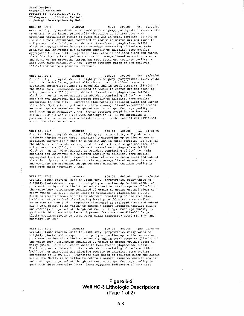
Shoal ProjectChurchill Co NevadaProject No. 764044.03.07.00.00IT Corporation Offsites ProjectLithologic Descriptions by Well
WEll ID. HC-3 GRANITE 0.00 200.00 jaw 11/04/96Granite, light grayish white to light pinkish gray, porphyritic, milky whiteto pinkish white kspar, principally microcline up to 15mm occura asprominant porphyritic subhed to euhed xls and in total comprise (35-40%) ofthe whole rock. Groundmass comprised of medium to coarse grained clear tomilky quartz xls (30%), minor white to translucent plagioclase «lO%).Black to greenish black biotite is abundant consisting of isolated thinbooklets and individual xls altering locally to chlorite, some smalleraggregates to 3 mm (10%), Magnetite also noted as isolated blebs and subhedxIs < 2mm. Spotty faint yellow to ocherous orange limonite/hematite stainsand coatings are prevelent throgh out most cuttings. CUttings quality isgood with chips nominally 2-4mm, larger cuttings noted in the interval110-120 indicating a possible fracture.
WEll ID. HC-3 GRANITE 200.00 300.00 jaw 11/04/96Granite, light grayish white to light pinkish gray, porphyritic, milky whiteto pinkish white kspar, principally microcline up to lSmm occura asprominant porphyritic subhed to euhed xls and in total comprise (35-40%) ofthe whole rock. Groundmass comprised of medium to coarse grained clear tomilky quartz xls (30%), minor white to translucent plagioclase «10%).Black to greenish black biotite is abundant consisting of isolated thinbooklets and individual xls altering locally to chlorite, some smalleraggregates to 3 mm (10%), Magnetite also noted as isolated blebs and subhedxls < 2mm. Spotty faint yellow to ocherous orange limonite/hematite stainsand coatings are prevelent throgh out most cuttings. CUttings quality isgood with chips nominally 2-4mm, larger cuttings noted in the interval210-220, 230-240 and 280-290 with cuttings to 10 -15 mm indicating apossible fractures. Schlerien foliation noted in the inteval 200-210'alongwith chloritization of rock.
WEll ID. HC-3 GRANITE 300.00 400.00 jaw 11/04/96Granite, light grayish white to light gray, porphyritic, milky white toslightly pinkish white kspar, principally microcline up to lSmm occura asprominant porphyritic subhed to euhed xls and in total comprise (35-40%) ofthe whole rock. Groundmass comprised of medium to coarse grained clear tomilky quartz xls (30%), minor white to translucent plagioclase «10%).Black to greenish black biotite is abundant consisting of isolated thinbooklets and individual xls altering locally to chlorite, some smalleraggregates to 3 mm (10%), Magnetite also noted as isolated blebs and subhedxls < 2mm. Spotty faint yellow to ocherous orange limonite/hematite stainsand coatings are prevelent throgh out most cuttings. CUttings quality isgood with chips nominally 2-4mm.
WEll ID. HC-3 GRANITE 400.00 600.00 jaw 11/04/96Granite, light grayish white to light gray, porphyritic, milky white toslightly pinkish white kspar, principally microcline up to 15mm occura asprominant porphyritic subhed to euhed xls and in total comprise (35-40%) ofthe whole rock. Groundmass comprised of medium to coarse grained clear tomilky quartz xls (30%), minor white to translucent plagioclase «10%).Black to greenish black biotite is abundant consisting of isolated thinbooklets and individual.xls altering locally to chlorite, some smalleraggregates to 3 mm (10%), Magnetite also noted as isolated blebs and subhedxls < 2mm. Spotty faint yellow to ocherous orange limonite/hematite stainsand coatings are prevelent throgh out most cuttings. CUttings quality isgood with chips nominally 2-4mm. Apparent fracture zone 410-450' largeblocky cuttings/rubble to 20mm. Other minor fractures? noted 530-540' andpossibly 590-600'.
WEll ID. HC-3 GRANITE 600.00 800.00 jaw 11/05/96Granite, light grayish white to light gray, porphyritic, milky white toslightly pinkish white kspar, principally microcline up to 15mm occura asprominant porphyritic subhed to euhed xls and in total comprise (35-40%) ofthe whole rock. Groundmass comprised of medium to coarse grained clear tomilky quartz xls (30%), minor white to translucent plagioclase «10%).Black to greenish black biotite is abundant consisting of isolated thinbooklets and individual xls altering locally to chlorite, some smalleraggregates to 10 mm (10%), Magnetite also noted as isolated blebs and subhedxls < 2mm. Spotty faint yellow to ocherous orange limonite/hematite stainsand coatings are prevelent throgh out most cuttings. CUttings quality isgood with chips nominally 2-4mm. Large cuttings indicative of potential
Figure 6-2Well HC-3 Lithologic Descriptions
(Page 1 of 2)
6-8

fractures or zones of fractures noted in the interval 630-640', 690-700'and720-7S0' cuttings i~ these intervals range from 10 -1S~~.
WEll ID. HC-3 GRANITE 800.00 880.00 jaw 11/0S/96Granite, light grayish white to light gray, porphyritic, milky white toslightly pinkish white kspar, principally microcline up to 1Smm occura asprominant porphyritic subhed to euhed xIs a~d in total comprise (3S-40%) ofthe whole rock. Groundmass comprised of medium to coarse grained clear tomilky quartz xIs (30%), minor white to translucent plagioclase «10%).Black to greenish black biotite is abundant consisting of isolated thinbooklets and individual xIs altering locally to chlorite, some smalleraggregates to 10 mm (10%), Magnetite also noted as isolated blebs and subhedxIs < 2mm. Spotty faint yellow to ocherous orange limonite/hematite stainsand coatings mostly on quartz xIs are prevelent throgh out most cuttings.Interval is mostly fractured with large (10-20mm) rubbly cuttings notedthroughout the interval.
WEll ID. HC-3 GRANITE 880.00 1060.00 jaw 11/0S/96Granite, light grayish white to light gray, porphyritic, milky white toslightly pinkish white kspar, principally microcline up to lSmm occura asprominant porphyritic subhed to euhed xIs and in total comprise (3S-40%) ofthe whole rock. Groundmass comprised of medium to coarse grained clear tomilky quartz xIs (30%), minor white to translucent plagioclase «10%).Black to greenish black biotite is abundant consisting of isolated thinbooklets and individual xIs altering locally to chlorite, some smalleraggregates to 10 mm (10%), Magnetite also noted as isolated blebs and subhedxIs < 2mm. Spotty faint yellow to ocherous orange limonite/hematite stainsand coatings mostly on quartz xIs are prevelent throgh out most cuttings.CUttings quality is generally good with cuttings ranging from 1-3mm.Interval 920-930'and 970-980'contain larger cuttings S-12mm suggestingpossible fracture zone.
WEll ID. HC-3 GRANITE 1060.00 1150.00 jaw 11/0S/96Granite, light grayish white to pinkish light gray, porphyritic, milky whiteto slightly pinkish white kspar, principally microcline up to lSmm occur asprominant porphyrltic subhed to euhed xIs and in total comprise (3S-40%) ofthe whole rock. Groundmass comprised of medium to coarse grained clear tomilky quartz xIs (30%), minor white to translucent plagioclase «10%).Black to greenish black biotite is abundant consisting of isolated thinbooklets and individual xIs altering locally to chlorite, some smalleraggregates to 10 mm (10%), Magnetite also noted as isolated blebs and subhedxIs < 2mm. Spotty faint yellow to ocherous orange limonite/hematite stainsand coatings mostly on quartz xIs are prevelent throgh out most cuttings.CUttings quality is generally good much of the interval is comprised oflarge rubbly cuttings (S-20mm) likely resulting from a fracture zone.
WEll ID. HC-3 GRANITE 1150.00 1303.00 jaw 11/06/96Granite, light grayish white to pinkish light gray, porphyritic, milky whiteto slightly pinkish white kspar, principally microcline up to 1Smm occur asprominant porphyritic subhed to euhed xIs and in total comprise (3S-40%) ofthe whole rock. Groundmass comprised of medium to coarse grained clear tomilky quartz xIs (30%), minor white to translucent plagioclase «10%)Black to greenish black biotite is abundant consisting of isolated thinbooklets and individual xIs altering locally to chlorite, some smalleraggregates to 10 mm (10%), Magnetite also noted as isolated blebs and subhedxIs < 2mm. Spotty faint yellow to ocherous orange limonite/hematite stainsand coatings mostly on quartz xIs are prevelent throgh out most cuttings.CUttings quality is generally good with a nominal size of 2.0-3.0mm.Possible fracture zone exists in the interval 1230 - 1240 as cuttings are8-12 mm.
Figure 6-2Well HC-3 Lithologic Descriptions
(Page 2 of 2)
6-9

15
14
.
rrQ:o100
"'1 10.0
.::0": 9.0 •
"l:5... 10 .j3. .....10.0
-'9.0
0';IB:o
')10.0
..r:tL..
~'29.0
I~·Q
<l15 ·9;0 .
l.~g ..0
B:O. ~cr
Water Production Rate(gpm)
.Date B""an:11/3/96
i Date Finished:11/10/96
0:0
f ·..I , ({~.O: .I BO
+· , ·· ..:·C=i.o=~-=LsA:.:·'~ ,O.O- ..
110:0i •,::,Ji:j8l
150
.....riijLX'X
•
•
·
·
......................f : : I~% ..180 ..
,10,0 ..........10.0
-/..6:0
f-&.Gr]d.. f · -r- ; .. •· .. ,!U· .. ··
............; f j'61,O 8:06.0
:~10.0:
~6.5
iEastina:560114.70Water Injection Rate
(gpm)
/4.4
o
l6.B
(48';:2:5.. ···· .. ·· ........;·
f , ;.!.U..6.4
~ .&4 ·B:O.. · ; ..
6:0f : ~I.U ·····..····· ..
f , :. ,,,6:2.-4: 6.0
6:0' :f · · ·; ·· ·I-6.j3.· , , + , ; ·J..M~ ·:··: , · ·jl6.0
10:0,· · ·• · ; ·..• ·f·10,O· ;..
10.0 •
; (.".,.5'1:.8 i L .
)~:5 •f .; II~%'· ..·..f .
/. 55f ~f.~.Q..
6:41..·.... ·.... ""··........ ·· .... :·1-6.-4
6.4
f ;)\t~ : j .<6.0
; ; ;/I.t~ .6.1,1
1cU5 •; · ·· ·.. ··· ·; ..· -: -] 18'Qo..i........... ·1 · ··: ···: ·...... .!:-~~"=i-'=:..:.:.. :.J
6.41..·.... ·.. ·..··,...... ·.... ·..·;·1-6.-4--
6.4
64. - . - ... ..
..;.-----8.0 ....,~o;........·....··,·........·<i{""':'!!~6· ...."t " ..·00-..···
f , , , ..-/ 10:0 ~20(91°,0 f.. · · ,............. ,· · ···,· '~.~ri2ii·
10:0;........ ·...... ,·........ ·.... ·:.. ·....·.. ·.. ··, ..<l·/9~00 l-f)13 0
·
I •
; , :/:ao:5.8
..-.--:.6.0
£'58f ......··...."..... ·....·,~o· ..........6.0
•
I
, , : (i8.~... ···l · : : : ;·~oo. ..
6.0_.... . -.- ···fjt'.eG---'
; , \;U ·
,....·......·.. ,· ..·......(;u· ....·.. ··
I
V ).60f...-."-1 ,· .. ·..-«:.. ~.0-'·5.,:5 .
F 10 LE'1'L -:-_--'t,..+i·~---_c_---~---+---__;_----;-::-=-:::::=;:;"'-£Kl----'------il\4:5 :
f ; ·j..).j:'47 :.
Northing:1618822.90
Geoloav and Water Production Summarv
ILithology I Rock [water
Type Ilevel
I Iv v vIGRANITEvVVV'vvv
vvvV'vvv
vvvV'vvv
vvvV'vvvvvvV'vvvvvvV'vvv~vvvV'vvv
vvvV'vvv
vvvV'vvv
vvvV'vvvvvvvV'vvvvvvvvvv
vvvV'vvv
vvvV'vvv
vvvV'vvv
vvvV'vvv
vvvV'vvv
vvvV'vvvvvvV'vvvvvvv
~t:::::::lvvvvvvV'vvv
vvvV'vvv
vvvV'
tVVVv vv ....,.vvv
vvvV'vvv
vvvV'
~::~::::vvv
vvvV'
~:::::::vvvvvvV'vvv
r:~:~:~:l~vvvvvvV'vvv
vvvV'vvvvvvV'vvv
vvvV'vvv
vvvV'vvvvvvvvvv
vvv'(JvvV' ~l
~~:~:~:~IvvvvvvV'vvvvvvv
:::::::~vvv
rVyVVVyV
~~v~«1r,VVV
f:::::::jvvvvvvvvvvv
rv v v
vvvV'vvv
vvvV'rvv"vvv....,.
~vVvVvVvvvvvvvV'vvv
~vvvvvvv
~vvvv
I:::::::vvvvvvV'vvv
vvvV'vvvvvvvvvvvvvv~vvvvvvV'vvvvvvV'vvv
vvvV'vvv
vvvV'vvvvvvvvvv
vvvV'vvv
vvvV'vvv
RockUnit
KGI
500
900
700
400
800
600
300
100
200
1100
1000
1200
Depth I Depth Strata(feet) ,(meters)
i
:Surface Elevation:5081.52
:Hole NO.:HC-3
ILogged By: Century GeophysicslDRI
II Drilling Co.: Beylik Drilling Services He-3 FluidDrillina Method: Air Rotarv/ Reverse Circulation
Figure 6-3Injection versus Production Diagram
IT CORPORATIONProject ShoalProject No. 764044.03.07.00.00
6-10

IDate Began·1113/96Geology and Geophysical Log SummaryHole No ·HC 3-Surface Elevalion:5081.52 Northing:1618822.90 iEasting:560114.70 Date Finished:11/10/96
Depth , Depth ~ Strata Rock PthOlog~ Rock 1 Water Spectra Gamma Ray Spectra Gamma Ray
I
Spectra Gamma Ray I
(feet) (meters) Unit
I I
Type level !I Potassium Uranium Thorium
II I (cps) (cps) (cps)
1~i ! 0 1000 0 2500v ,
U r v v, KG~:vv
GRANITE"20 -1 ~vvvvl
vvvv
40 ~lvVV ~vvvv.Jvvvvv
rr v v vv60 I
20}VvVv?l vv80..:1
vv
{~V~Vlvv
100 ~vvvv
vv vvI
120 ~.Jvvv vv"
40 1.....: .....: ..... vvlvvvv~
140 -1 sr«: v v ~
160 -j , vv~vv~tv""""
vv~180 ]
;vvv
~~~'-"vv200 60 -tv....."",....."", vvl
iVV~ vv,220 I
-"vv vvvvjIvvl
240 ~ Tv""'.....""'..... vVvvJ, "'vv
r~~l260 j 80 --\,vvvv'(J ;i-
280 ~-tvvvvvi
~vv~
f v vv1
vv >--vv300_vvvvl rv
320 Ivy v vv :t1°Oivvvv ..... vvl
340~ vVJ-"vv vv
360 J j.v...............'<J :""':""'1380 j j.v.....v.....'<J vv
:vv'(J vv i.~120iv:V:V1
vv400 -j rv
IVV~ vv ..-420 "j
l v:V::1
vv~vv
440 ~vv
lv V v
~~~:io'vv
460 140 "1vvvvvl480 -i l,vvvv1500 -j "'"1 v v v
... vv""!~
-
~q1-vvvv~ vv,vv,
160}VvVv1 vvvv~ ;L '-,vvvv1vv
-'l.o",.....vv"'" ~~j "-560.J ~vv
580...1Jvv v
~vvvv"'vv-..:
600 ~ 180---l~VvVv~ VVVV
~ ";io'vvv.....'<j vvrvvv
620 -i -t.vvvv~ I" vvvvJ640 ~ j V
vVv 1
~~:~~;i;-
660 j 200 "VvVvl i- =-ivv .....680 lvv ,-700 ~
""vvvv'<J p"vv ~iVvvvvl vv
720 j p"vv
I220 .v v -.?i vv
IvvvV1 c-: v vvv
740 ~~V~~!
rvvvrv760 vvIV""'''''' ::::j780 J ->-vv
IVY v~
800 .~240 "" v vvvv
-vv:vv v'
~~~j820 "J -rvvvv~
:q i vv ",""'.)
2601v:V::1VVj
880 r v v vv
VVI tv::
v::J9OO-i
vvvvv
920 j ~vv v~::v::vJ280-rvv .....v .....
-ivv ....."",.....
EV V
""1vv
~V::V::1vv
960vvvv
VVV.....'<J vv980 vv
300 "1,vvVyYI VV ,~1000 ., vv
iYY~ vv e--1020 ~
.vv t v v-!VV1
~~~1_VV
1040~tVvVv
!320-irvvvvv1OS01 -.YVV
_v vv Vj1080 J ..,vvv vv
SL.v v vv
1100 ~"V v VI
VVVVj1120 340-tv:V::1
~:::::F UID lEVI L
JVYV1140 • vv
1 {VVVy~
~vv~1160~ -{.vyVyVI vv
360 -{.Vvyy~vv
1180 vvtyvv
1200 ]-l.vvyv~ tvYVVy~ ,1VV1 ~vv
1220 -rv.....-r: i/' VVvv~
1240i"Vy '"vvIVYV v:vvyYJoj 38°1vvvvv
1260 l "vv ~-Yvv vv
tY V V vv
•
1280 3 vv<-vv~~vvv
."vv ,,·vv
Loggeq By: Century Geophysics/DRI IT CORPORATION IDrillin .: B lik ri in Ig Co ey D II 9 Services • Project Shoal
IDrillingMethod: Air Rotary/ Reverse Circulation Figure 6-4 Project No. 764044.03.07.00.00
HC-3 Geophysical Log Traces of Spectra Gamma Ray6-11

IGeology and Geophysical Log Summary
Date Finished:11/10/96
Date Began:11/3/96Hole NO.:HC-3
Surface Elevation:5081.52Depth Depth Strata Rock(feet) meters Unit
ithologINorthing: 1618877.60
Rock WaterType Level
o
Caliper(inches)
IEasting:560392.60
200
Resistivity(ohmlm)
(log not run)5000
Neutron(cps)
(log not run)2000C
1020
1040
1060
1080
1100
1120
1140
1160
1180
1200
1220
1240
1260
1280
1300
320
340
360
380
vvvvvvvvvvvvvvvvvvvvvvvvvvvvvvvvvvvvvvvvvvvvvvvvvvvvvvvvvvvvvvvvvvvvvvvvvvvvvvvvvvvvvvvvvvvvvvvvvvvvvvvvvvvvvvvvvvvvvvvvvvvvvvvvvvvvvvvvvvvvvvvvvvvvvvvvvvvvvvvvvvvvvvvvvvvvvvvvvvvvvvvvvvvvvvvvvvvvvvvvvvvvvvvvvvvvvvvvvvvvvvvvvvvvvvvvvvvvvvvvvvvvvvvvvvvvvvvvvvvvvvvvvvvvvvvvvvvvvvvvvvvvvvvvvvvvvvvvvvvvvvvvvvvvvvvvvvvvvvvvvvvvvvvvvvvvvvvvvvvvvvvvvvvvvvvvvvvvvvvvvvvvvvvvvvvvvvvvvvvvvvvvvvvvvvvvvvvvvvvvvvvvvvv
IVF UID LEV l
I
Logged By: Century GeophysicslDRI
Drilling Co.: Beylik Drilling Services
IDrilling Method: Air Rotaryl Reve£se Circulation Figure 6-5
IT CORPORATIONProject ShoalProject No. 764044.03.07.00.00
HC-3 Geophysical Log Traces of Caliper, Resistivity, Neutron6-12

Hole NO.:HC-3 Geology and Geophysical Log Summary i Date Beoan:11/3/96
ISurface Elevation:5081.52Deplh rDepth !.. Strala! Rock(feel) meters) I Unit
,! I I
~lthOlog~
I I
I
INorthino161882290Rock IWater IType Level 10
Caliper(inches)
IEasting:560114.70
200
Gamma Ray(api)
!Date Finished:11/1 0/96
.[' Density(gmlcm3)
10000
I
IJ,
.~.
~~
.~.
-~
~- -- ------,----, -i-----i------!-----f-----i.- i· .i.-.-::;::::-+:-'~ .;.-----,----+--
" fr:-~1'!
.....
-r-;
~
-----
~~
~
~
~
'f~
Ir';-...:
F-~~!
1:
:r'po
.5Lr-----:-7-C---7-_;_--'--'----'--7-+-~__7__;_---;-----__;__-:.-'_____',______;__+______;_______;______+_+__+_----'-----'------'--'-----1F UIDlEII! L
f-!------!---,-----;+-- -< --, .., ...., t-·-
GRANITE
20
40
60
80
100
120
140 -j160 l180 l
~~~ j.J
240
260 j280
300
320
340 1360 -i
380 j:~~ 3440 ~
:~jl500
520
540 J560 ~580
1600
620
640 l660 1680 -j700.J
720 ~740 -I760 ..J
780 ~800 l820 ~840 -l660~880 ~900 1920 -j940 l960 1980 -j
1000 ~1020 ~1040 11060 11080 l
~~~~ ~1140 -j1160 11180l
1200 l1220 .~
1240 -:11260 !
iLogged.By: Century Geophysics/DRI IT CORPORATION.Drilling Co.: Beylik Drilling Services • Project ShoaliDriliing Method: Air Rotaryl Reverse Circulation Figure 6-6 Project No. 764044.03.07.00.00
HC-3 Geophysical Log Traces of Caliper, Gamma Ray, Density6-13
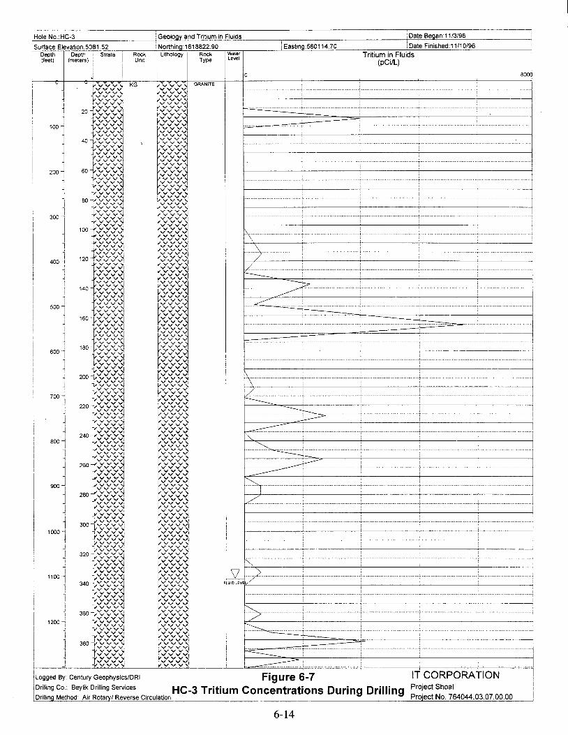
IT CORPORATIONProject Shoal
Project No. 764044.03.07.00.00
:Date Began 11/3/96iGeology and Tritium in Fluids
ILogges By: Century Geophysics/DRI Figure 6-7Drilling Co.: Beylik Drilling Services HC-3 Tritium Concentrations During DrillingDrillin Method: Air Rota I Reverse Circulatior, _-,--,==c.:..:.=':""=====':"::==__..J
'Hole NO.:HC-3
Surface Elevation:5081.52 iNorthina:1618822.90 j Eastina:560114.70 ,Date Finished:11/10/96Depth Depth , Strata
IRock I Lithology Rock i Water Tritium in Fluids 1
(feet) (meters) ! Unit Type ! Level(pCilL) ii
II I
J I 0 800q
vvvv-.J KG ~......vvvvvvGRANITE
~ ~VvVvVvVII rvv1--VvVvVv~ vvvv
l vvv
'00I 1VVV1 vvvvII"'VVV vvv
20--: v v v VI VVVV
"vvv~
VV"''''l...J.vvvv!lVYV vvv
i--v v v v vvvvvvv~ VVVV
i--VVVVI ~vvvv
vvv~ vvv40 -;,..vy"""y"""y""" iV V v ......
t-vv"""v"""v"(J
r~~~l.JvvvlIv"'",""","'...... vvvvvvv
-r v v v vvv
200l 60 vvvvvv~ vvvvvvv
:VVVVI vvvv
~l'vvv~ vvv-j.,v v v v VVVVlvvv.±VvVvVv'(J vvvv
vvvvvvv yVVVV
~80 vvv~ vvv
IVV,,"VI vvvv-yvvV'oj yo ...... v ......
I -l..-vy"""y"""v'<.l ~vvvvvvv
300I iVVVVI ~v V v VI+vvv~ v~v:v:~]vvvv
100 ,vvvvvv~:
V V V 1I IvVvVvVv' ~vvvvvv1.\
I
l vvv~ vvv\vvvv vvvv
1vvv vvvVVV1 VvVvVvl
..... j400 -t 120 tv"'......"'......"'...... vvvv
/1 vvvvvv~ vvvvvvv
1 YVVV~ vvv t'----.-I lvvvvvvv vvvvvvl1 vvv~ vvvv --~vvv1 '" "''''vv1
vvvv .... ------.- "7tVVVvvvv VW
1500J vvv vvv .>vvvv ~vvvv ..vvv vvv! vvvv ~vvvv
1 vvv vvv1601.-v v v 1 vvvv
J vvv vvv-IVYVV
~:«vl! iVY'"1 VVVV!
_fvvvvv1vvv
J vvvvI vvv vvv
600l 180 v v v ..... , tV'" VVIvvv vvv~}vvvvvv~
r~~~l~tVVV~vvv ~yYyYvYvvvv~
~vvv~ zoot>(;,<;v YVYV
vvv .\J VVV~ vvvv
vvv~vvvvvvvI VVvVVV~ 7
700~vvv
vvvvvy '1 VVYV~
........vvv
220 -r:v:v:vJ1 r~~V~l -------:~I 1I'vvv~ f"vvv .s->tv v v y, ~VVYV.j VYV"'; vvv
~-VVyVVvV~ vvvv ....-----vvv
240 -i--vVVyVV~ ~VVVVVyY -. ........
800...j ...j,..vvVyVvVI ~vvvvvvv~
..~I rvv~ 1VVVl1 VYV~ rvv .., vv,,"vi
~~V~l ---~~
VVv ....iVVV1 ~:.----260 -tvvvvvvv vvv
vvvv .. .~ ...vVVV'\i vvvrvv'(J vvvv
900Jvvv vvv r-.vvvvvv'<J IVVV"",
~VVV ·······1I
rv~vvvv
I 280 vvvvvv~ vvv] vvv
t~V~~l../"
vvv1J vvv vvv
Wvl vvvvvvv
I YVYV ~vvvv
1 vvv vvv300-tv v v v vvvv
vvv vvv1000..., lVVVV IVVVV
~vvv VVVVYVV1 ~vvvvvvv
J VVVV
1vvvl
Ivvv vvv
320{VVVV VVVY"1
vvvrvvvvv'(J~vvvv r-.vvv vvv
i I 1VvVvVvV VVV1 jL '>vvvI 1100"1 vvvv vvvvI vvv vvv 1'/I
340 v v v '(J Ivvvvi F UID LEVI
1 vvv VVVV~yvvvi IVVVV
I I vYVV~ ~v:v:v:~..J.Vvvv
I "1Yvvvvvv\j ,vvvi r-,vvvv r",vvv",vv,
360 ~vYvv.....""'v1
II ~vvv~ "7
1200"1 ~V.....""'vVv\Jvvvv~vvvvvv~ ~.I " J,..Vv
Vv
Vv 1 vVyVVY..),
I I ~vvv1
Ivvv YV""'~
J 380 ""'v""'v""'v"'" (vVvVvl .. jtv v v \I vvvv~
..... ....._................. ............ .......... ......... .. ......... ....... . .................• .....................
~vvv vvvv
-v""'.....""'v..........~ ~vvvvI vvv
~. uuu uuuu+II -i-vvv....."",v'(J kVvvvvv'J.. . ................. - .... ..-. . ......... . ..... . ........... - ...
I
6-14

Hole No.:HC-3 Geoloav and Well Construction Summarv Date Began:11/3/96
Surface Elevation:5081.52 iNorthing: 1618822.90 IEastina:560114.70 iDate Finished:11/10/96 iDepth
I (~:iet~) iSt~t·1Rock i ""] Rock I Waler Caliper
IWell Construction Ii
(feet) Unrt
I I
Type Level(inches)
I
r I 0 201
:: ~} v ~ KG t--':''' GRANITE ::-..:. ,:.-.:r}l ~,:
....•_:::! ;:;.-:+ CEMENTYvv V': ~ ;:;.--.. _-E-::
~i!:--
60 20 {v:t--:Y p CASING 8.625" 0-103.0v:-;' ::"'~
80 .v
~~i:"'~ --~v --100 1 -j,.vv
120 j40
J:vi :-;.
r:5- ? '" CENTRALIZER 98.0-99.0140 ,
~::160 ~ r':'V
~ BOREHOLE 12.0" 0-103.0180 \.
I200 1 6°1v:1 ~:~Vv':1 ~
"(J220 ":1 vv':1
~:j>-
240 1Vvj >0'
260 J 80+~v I280 tv>~ V:v1300
Vv~ ~:j I320 ~ 100 -J,Vv ;;;:r">340 -J..vv':1
r360~
-J..Vv J I
±VvJ,=
380 ..>4001 120 r:v ~ :..-v
-r v~ :,,-v ~'420 -j t~:~ j-< I440 -l
'~fJ:,,-v
-t j460 --1 f-·· ....
4801 Vv'<l l,':';-j
5001 }vv'<l l,~1
:~ 160-r::~ t:j ,
}VV~ l,vJ I--- CASING 5.5" 0-1094.4560~ ~vv r v-J I
1vv ~vd
I580 .., "600~ 'Ml::~ ~~q .....620 -' ~v rv640 j vv
tV rv~
200 i:: V1~j vj680 tVv~ rVJ ~:700 V '<I I v!
720 3 220 t::1rv'1 BOREHOLE 8" 103.0-1303.0
~:j10-:
740 ~
760 1 fv'<lv1
~:J780 1 '~~~~800 ~ -i'v e820 .j.,Vv :3:~1
.j.,Vv
,.~VVjvi
~Iv:~ =~v
880 j,vv
2801::~tv
'1900 -t vj920 -l
1 l,vd :t-940 1 t::~
tv :r960 -'
'oor~~'v;J I
980 ~ rv-J,
~vJ ,1000 -1 v:~ rvl :1020 -j
~:1rv'1
1040-i rvj
1060-:]320 vv'<l v-J
1080 -i t::J ~:~1100 ~ SL
340 1v:~ bV~ +++++++++++++++++++.1120-1
UIDlEVIl +++++++++++++++++++.+++++++++++++++++++.
1140 -j}::j
,:~ ++++++++++++++++++++++++•••++++++++++++•
• ++.+.++++++++++++++1160 -1 Vvj ++++++++++++++++++++ I,
360{:~~++++++++++++++++++++
I l t] ~++++++++++++++++++++ I! 1180 ~ ++++++++++++++++++++
I++++++++++++++++++++
i 1200
~:+++++++++++++++++++++++++++++ +++
12201 t:v~++++++++++++++++ FILL 1104.00-1303.0
i ++++++++++++++++++++++++++++++++++++++++I ... v~
~~++++++++++++++++++++
I 1240 "j 380...j..vv ++++++++++++++++++++
L126~j t::~++++++++++++++++++++
++++++++++++++++++++I . ++++++++++++++++++++
1280 ++++++++++++++++++++++++++++++++++++++++. . . , . .
:::::.+:::.+.+,,:.+,:::.+:.+.... ...- ....• ".: ...:,,:..:.~~~.:..:.:.L-__
ILogged.By: Century GeophysicslDRI Figure 6-8 IT CORPORATIONIDrilling Co.: Beylik Drilling Services • • Project Shoal!Drilling Method: Air Rotary! Reverse Circulation ~~-!_~_~~~.~.~.!~e W!~I_CO~I?!~!~~~P~.~!I.~am Project No. 764044.03.07.00.00
6-15

Well Coordinates(State Planar NAD 27)N: 1618877.565E: 560392.641
Clamp/ Landing Plate
Well Pad
1.22 m x 1.22 m x 0.15 m(48 in x 48 in x 6 in)Reinforced with a 15.2-cm x 15.2-cm(6 in x 6 in) wire mat
E ~
'" to"'::!.
1.22 m
(48 in)
Plan View
• IProtective Casing
32.38-cm (12 3/4 in) od0.32-cm (.125 in) wall
Surface Casing
21.91-cm (8 5/8 in) odOA8-cm (.188 in) wall
Intermediate Casing
13.97-cm (5 1/2 in) od12.70-cm (5.0 in) id
Data Logger Access Tube
3.81-cm (1 1/2 in) conduit
Shelter for Data Logger
60.96-cm (24 in) diameter pad
~ ~ Lockable Lidn .~
LO LO
32.38-cm (12 3/4 in)od Protective Casing~ r--r--: <D~
Cap 13.97-cm (5 1/2 in) od ThreadedE .sor-- 0
N 0.0~
Intermediate Casing with 13.97-cm
E (5 1/2 in) od Threaded Couplingo .s
LO LO
r--: r--<D
Data Logger Access Tube0
;E .o .sr-- LOen
<'"i 0.00 £~
E 1o .~
III<X> 0r-- r--: I Concrete Padr--:
~ 1 .If-- .. .. .. I . ' .. ...
Ground Surface E .: ..... ; ..: /:,:' 1 : •... :~.~: .~.o .~ .", .:... ',
.', .:..Elevation -e-0 . : ... ',: ..
,/\ I : ..... :~.~: .~.N1548.85 m 0.0 <D ......:.....
I....:..
(5081.52 ft) ~ ~: .~:.:::." :.,,-:,: .:.: ....I
110.\\11 A \.- /}"\\Y ,,\\Y. I I 1\' ' .. '/'1.\' ,1\ \ \ Y1\' ,~ ''" .-
~ - , .\. d- ~ .... - ~
i-,~- Surface Casing
.Clamp/Landing Plate
Figure 6-9HC-3 Well Head Completion Diagram
6-16

Table 6-1HC-3 Lithium Bromide Concentrations
Date Time Depth Sample Cone. Sample Temp
mm/dd/yy (24 hrs) (tt) (mg/L) (Co) Sample Source Analysis By11/4/96 2330 NA 19.9 26.3 QA Standard AM. Welcher11/4/96 2225 NA 28.8 26.0 Water Truck AM. Welcher11/4/96 2230 623 29.7 26.0 Discharge Line AM. Welcher11/4/96 2330 643 29.3 26.0 Discharge Line AM. Welcher11/5/96 0040 683 20.4 26.0 Discharge Line A.M. Welcher11/5/96 0145 703 30.5 26.1 Discharge Line A.M. Welcher11/5/96 0230 NA 20.0 25.7 QA Standard A.M. Welcher11/5/96 0145 NA 29.7 26.1 Water Truck A.M. Welcher11/5/96 0245 NA 28.9 25.7 Water Truck AM. Welcher11/5/96 0245 743 29.8 25.7 Discharge Line AM. Welcher11/5/96 0345 780 31.3 25.7 Discharge Line AM. Welcher11/5/96 0445 790 31.7 25.9 Discharge Line AM. Welcher11/5/96 0550 NA 20.0 25.6 QA Standard AM. Welcher11/5/96 0545 820 31.4 26.1 Discharge Line J. Wurtz11/5/96 0615 840 30.7 25.6 Discharge Line J. Wurtz11/5/96 0700 860 36.6 25.7 Discharge Line J. Wurtz11/5/96 0730 880 38.7 25.7 Discharge Line J. Wurtz11/5/96 0800 900 42.4 25.7 Discharge Line J. Wurtz11/5/96 0845 NA 20.1 20.1 QA Standard J. Wurtz11/5/96 0830 NA 43.1 25.8 Water Truck J. Wurtz11/5/96 0830 920 47.5 25.7 Discharge Line J. Wurtz11/5/96 0900 NA 47.5 25.9 Water Truck J. Wurtz11/5/96 0915 940 45.9 25.9 Discharge Line J. Wurtz11/5/96 1110 960 43.4 25.9 Discharge Line J. Wurtz11/5/96 1330 NA 20.2 25.8 QA Standard J. Wurtz11/5/96 1135 980 44.9 26.0 Discharge Line J. Wurtz11/5/96 1210 1000 45.4 26.0 Discharge Line J. Wurtz11/5/96 1305 1023 41.5 25.9 Discharge Line J. Wurtz11/5/96 1320 1043 39.5 25.9 Discharge Line J. Wurtz11/5/96 1400 1060 39.4 25.9 Discharge Line J. Wurtz11/5/96 1430 1083 44.5 25.9 Discharge Line J. Wurtz11/5/96 1800 NA 23.9 25.0 QA Standard P. Gallo11/5/96 1930 NA 20.0 25.4 QA Standard AM. Welcher11/5/96 1500 NA 36.7 25.4 Water Truck AM. Welcher11/5/96 1500 1090 39.0 25.4 Discharge Line A.M. Welcher11/5/96 1600 1120 26.7 25.4 Discharge Line AM. Welcher11/5/96 1640 1143 29.6 25.4 Discharge Line AM. Welcher11/5/96 1710 1163 27.5 25.4 Discharge Line AM. Welcher11/5/96 2115 NA 20.0 25.9 QA Standard AM. Welcher11/5/96 1740 1183 30.8 25.9 Discharge Line A.M. Welcher11/5/96 1820 NA 29.9 25.9 Water Truck AM. Welcher11/5/96 1820 1203 34.8 25.9 Discharge Line AM. Welcher11/5/96 1905 NA 21.1 25.9 Water Truck AM. Welcher11/5/96 1905 1223 23.6 25.9 Discharge Line A.M. Welcher11/5/96 2400 NA 20.0 25.7 QA Standard AM. Welcher11/5/96 2005 1243 19.8 25.7 Discharge Line AM. Welcher11/5/96 2105 1263 21.0 25.7 Discharge Line A.M. Welcher11/5/96 2200 NA 20.6 25.7 Water Truck AM. Welcher11/5/96 2200 1283 18.5 25.7 Discharge Line AM. Welcher11/5/96 2305 1303 18.4 25.7 Discharge Line AM. Welcher11/6/96 0030 NA 20.0 25.3 QA Standard AM. Welcher11/6/96 0230 1303 16.5 25.3 Circulating AM. Welcher
6-17
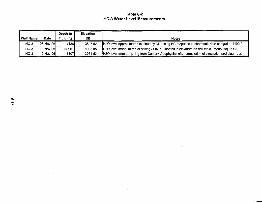
0\I...-00
Table 6-2HC-3 Water Level Measurements
Depth to Elevation
Well Name Date Fluid (tt) (tt) Notes
HC-3 06-Nov-96 1186 3895.52 H20 level approximate.Obtained by DRI using EC response in chemtool. Hole bridged at 1190 ft.
HC-3 09-Nov-96 1077.67 4003.85 H20 level meas. to top of casing (4.82 ft); located in elevators on drill table. Meas. adj. to GL.
HC-3 10-Nov-96 1107 3974.52 H20 level from temp. log from Century Geophysics after completion of circulation and clean-out.
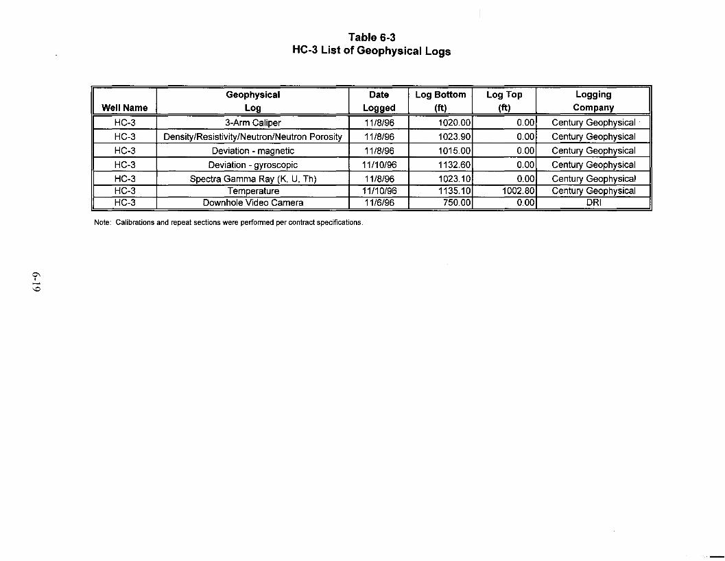
0'\I-'0
Table 6-3HC-3 List of Geophysical Logs
Geophysical Date Log Bottom Log Top Logging
Well Name Log Logged (ft) (ft) Company
HC-3 3-Arm Caliper 11/8/96 1020.00 0.00 Century Geophysical
HC-3 Density/Resistivity/Neutron/Neutron Porosity 11/8/96 1023.90 0.00 Century Geophysical
HC-3 Deviation - magnetic 11/8/96 1015.00 0.00 Century Geophysical
HC-3 Deviation - gyroscopic 11/10/96 1132.60 0.00 Century Geophysical
HC-3 Spectra Gamma Ray (K, U, Th) 11/8/96 1023.10 0.00 Century GeophysicalHC-3 Temperature 11/10/96 1135.10 1002.80 Century GeophysicalHC-3 Downhole Video Camera 11/6/96 750.00 0.00 DRI
Note: Calibrations and repeat sections were performed per contract specifications.
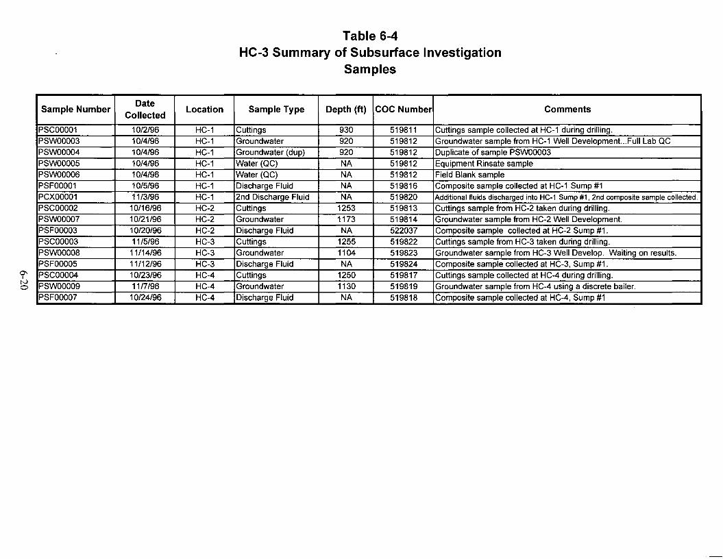
0'1I
tvo
Table 6-4HC-3 Summary of Subsurface Investigation
Samples
Sample NumberDate
Location Sample Type Depth (ft) COC Number CommentsCollected
PSCOOO01 10/2/96 HC-1 Cuttings 930 519811 Cuttings sample collected at HC-1 during drilling.PSWOOO03 10/4/96 HC-1 Groundwater 920 519812 Groundwater sample from HC-1 Well Development...Full Lab QCPSWOOO04 10/4/96 HC-1 Groundwater (dup) 920 519812 Duplicate of sample PSWOOO03PSWOOO05 10/4/96 HC-1 Water (QC) NA 519812 Equipment Rinsate samplePSWOOO06 10/4/96 HC-1 Water (QC) NA 519812 Field Blank samplePSFOOO01 10/5/96 HC-1 Discharge Fluid NA 519816 Composite sample collected at HC-1 Sump #1PCXOOO01 11/3/96 HC-1 2nd Discharge Fluid NA 519820 Additional fluids discharged into HC-1 Sump #1, 2nd composite sample collected.
PSCOOO02 10/16/96 HC-2 Cuttings 1253 519813 Cuttings sample from HC-2 taken during drilling.PSWOOO07 10/21/96 HC-2 Groundwater 1173 519814 Groundwater sample from HC-2 Well Development.PSFOOO03 10/20/96 HC-2 Discharge Fluid NA 522037 Composite sample collected at HC-2 Sump #1.PSCOOO03 11/5/96 HC-3 Cuttings 1255 519822 Cuttings sample from HC-3 taken during drilling.PSWOOO08 11/14/96 HC-3 Groundwater 1104 519823 Groundwater sample from HC-3 Well Develop. Waiting on results.PSFOOO05 11/12/96 HC-3 Discharge Fluid NA 519824 Composite sample collected at HC-3, Sump #1.PSCOOO04 10/23/96 HC-4 Cuttings 1250 519817 Cuttings sample collected at HC-4 during drilling.PSWOOO09 11nJ96 HC-4 Groundwater 1130 519819 Groundwater sample from HC-4 using a discrete bailer.PSFOOO07 10/24/96 HC-4 Discharge Fluid NA 519818 Composite sample collected at HC-4, Sump #1

0\I
N.......
Table 6-5a to 6-5eHC-3 Sample Results
(Page 1 of 3)
Table 6-5a
Sample Sample Aluminum Antimony Arsenic Barium Beryllium Boron Cadmium Calcium ChromiumLocation Sample # Date Matrix (mg/L)a (mg/L) (mg/L) (mg/L) (mg/L) (mg/L) (mg/L) (mg/L) (mg/L)
HC-3 PSCOO03 11/5/96 Cuttings N/Ab N/A N/A N/A N/A N/A N/A N/A N/AHC-3 PSWOOO08 11/14/96 Groundwater N/A N/A 0.0018 (ND)" 0.0472 N/A N/A 0.0006 (ND) N/A 0.0394HC-3 PSFOOO05 11/12/96 Sump N/A N/A 0.0018 (ND) 0.138 N/A N/A 0.0006 (ND) N/A 0.0032
Table 6-5b
Sample Sample Cobalt Copper Iron Lead Lithium Magnesium Manganese Mercury MolybdenumLocation Sample # Date Matrix (mg/L) (mg/L) (mg/L) (mg/L) (mg/L) (mg/L) (mg/L) (mg/L) (mg/L)
HC-3 PSCOO03 11/5/96 Cuttings N/A N/A N/A N/A N/A N/A N/A N/A N/AHC-3 PSWOOO08 11/14/96 Groundwater N/A N/A N/A 0.0414 N/A N/A N/A 0.00024 N/AHC-3 PSFOOO05 11/12/96 Sump N/A N/A N/A 0.0049 N/A N/A N/A 0.00016 N/A
"Milligram(s) per liter
bNot Analyzed
CReportedvalue is below the detection limit.
dUnits in picoCuries per liter (pCi/L) unless otherwise noted.
ePicoCuries per gram
'Not detected
-

Table 6-5a to 6-5eHC-3 Sample Results
(Page 2 of 3)
Table 6-5c
Sample Sample Nickel Potassium Selenium Silicon Silver Sodium Strontium ThalliumLocation Sample # Date Matrix (mg/L) (mg/L) (mg/L) (mg/L) (mg/L) (mg/L) (mg/L) (mg/L)
HC-3 PSCOO03 11/5/96 Cuttings N/A N/A N/A N/A N/A N/A N/A N/AHC-3 PSWOOO08 11/14/96 Groundwater N/A N/A 0.0028 (ND) N/A 0.0015 (NO) N/A N/A N/AHC-3 PSFOOO05 11/12/96 Sump N/A N/A 0.0028 (ND) N/A 0.0015 (NO) N/A N/A N/A
Table 6-5d
Sample Sample Uranium Vanadium Zinc Tritium Gross Alpha Gross Beta Bismuth-214 Cesium-137.L' n Sample # Date Matrix (mg/L) (mg/L) (mg/L) (pCi/L)d (pCi/L) (pCi/L) (pCi/L) (pCi/L)
HC-3 PSCOO03 11/5/96 Cuttings N/A N/A N/A N/A N/A N/A NOt pCi/g e 0.18 (NO) pCi/gHC-3 PSWOOO08 11/14/96 Groundwater N/A N/A N/A -372 163 39.9 NO 7.15(NO)HC-3 PSFOOO05 11/12/96 Sump N/A N/A N/A -30 17.5 6.62 NO NO
aMilligram(s) per liter
bNot Analyzed
CReported value is below the detection limit.
dUnits in picoCuries per liter (pCi/L) unless otherwise noted.
ePicoCuries per gram
fNot detected

0'1Itvw
Table 6-5a to 6-5eHC-3 Sample Results
(Page 3 of 3)
Table 6-5e
Sample Sample Lead-212 Lead-214 Potassium-40 Thallium-208 Thorium-234Location Sample # Date Matrix (pCi/L) (pCi/L) (pCi/L) (pCi/L) (pCi/L)
HC-3 PSCOO03 11/5/96 Cuttings 0.31 pCi/g 0.70 pCi/g 41.7 pCi/g 0.23 pCi/g NO pCi/gHC-3 PSWOOO08 11/14/96 Groundwater NO NO NO NO 75.5HC-3 PSFOOO05 11/12/96 Sump NO NO NO NO NO
aMilligram(s) per liter
bNot Analyzed
CReported value is below the detection limit.
dUnits in picoCuries per liter (pCi/L) unless otherwise noted.
ePicoCuries per gram
fNot detected

This page intentionally left blank

7-1
7.0 Well HC-4 Summary of Operations
Well HC-4 was drilled to a depth of 397.15 m (1,303.0 ft) between October 20, 1996, and
October 25, 1996. Five days were spent drilling and completing the installation of this well. Note
that Figures 7-1 through 7-10, cited in the following text, are located at the end of this section.
Prior to mobilization, all drilling equipment was decontaminated at the on-site decontamination
pad using a combination of steam cleaning and high pressure washing. Decontaminated
equipment was subjected to a radiological screening prior to mobilization to the drill site.
A 30.48-cm (12.0-in.) hole for the surface conductor was drilled using reverse air rotary reverse
circulation techniques and a 30.48-cm (12-in.) downhole percussion hammer to a depth of
31.39 m (103 ft) bgs. A 21.91-cm (8.625-in.) carbon steel casing was installed in this hole and
cemented to the surface using Type II cement without the requested 2 percent calcium chloride
additive. The lack of calcium chloride resulted in an estimated ten additional hours waiting for the
cement to cure.
The main hole was drilled from below the casing point to a TD of 397.15 m (1,303.0 ft) bgs using
a 20.32-cm (8.0-in.) percussion hammer button bit and air rotary reverse circulation techniques.
Drilling progressed smoothly during the advance of the main hole. Rates of penetration were
high, ranging from 1.64 to 4.26 minutes per meter (0.5 to 1.3 minutes per foot). Some short
delays to the drilling progress resulted from leaks/washouts of the discharge hose or cyclone;
repairs were made quickly; and drilling resumed. Figure 7-1 provides a summary of drilling
parameters for the well. All figures and tables, cited in the text, are located at the end of this
section.
Upon completion of drilling operations, the well was circulated for a short period of time. The
drill pipe was then tripped out of the hole to a depth of 365.76 m (1,200.0 ft). After waiting for a
period of one hour, the drilling assembly was tripped into the hole to a depth of 397.15 m
(1,303.0 ft) to check for fill. No fill was encountered. The drilling assembly was then pulled from
the borehole in preparation for geophysical logging.
Geophysical logging commenced on October 23, 1996, and was completed on October 24, 1996.
Logging proceeded smoothly with all geophysical logging runs conducted to a depth of 394.41 m

7-2
(1,294.0 ft). The downhole video was completed to a depth of 317.91 m (1,043.0 ft); logging
was not continued below this depth due to the turbidity of the fluid in the borehole.
7.1 Well HC-4 GeologyWell HC-4 encountered a fractured, coarse-grained biotite granite of Cretaceous age throughout
the drilled interval. Three significant fault/fracture zones were encountered in the well. The first
was located between 134.11 to 146.30 m (440.0 to 480.0 ft), apparently related to the occurrence
of an aplite dike. A second, broader fracture zone was encountered in the approximate interval of
243.84 to 274.32 m (800.0 to 900.0 ft); granitic rocks within this zone were also hydrothermally
altered with the development of some clays and pervasive chloritization. This alteration
assemblage is typical of those recognized along fracture and fault zones intruded by Tertiary-aged
andesite dikes; however, no andesite was noted during the collection of cuttings during drilling
operations. A lithologic log is provided as Figure 7-2.
7.2 Well HC-4 HydrologySeveral elements of hydrologic importance were monitored during and after the completion of
Well HC-4. During drilling operations, two monitoring parameters were consistently compared:
the volume of drilling fluids (water/foam) injected to facilitate drilling and volume of fluid
produced as discharge to the surface during the same time. Figure 7-3 illustrates the relationships
between injected drilling fluids and drilling fluid produced at the surface.
In addition to these volumetric measurements, all drilling fluids injected into the borehole were
tagged with a tracer solution of LiBr. The concentration of LiBr in solution was monitored on a
regular basis to estimate groundwater production within the borehole. Table 7-1 lists LiBr
concentrations recorded in produced fluids.
Water production from the well was minimal; monitoring data and water-level recovery data
suggest the well was capable of producing approximately 2.8 to 3.8 L/min (0.75 to 1.0 gpm).
During several instances, the well was capable of intermittent production on the order of
11.4 to 18.8 L/min (3.0 to 5.0 gpm). These somewhat higher readings suggest groundwater
production from perched water zones along fault or fracture zones. These zones were of limited
impact as their storage capacities were generally small, and as they were exhausted, their
contribution of water to the well bore decreased.
Water-level monitoring was conducted during the construction of the well and continued after
completion using transducers set by DRI. The static water level for Well HC-4 is approximately

7-3
317.20 m (1,040.0 ft) bgs. Table 7-2 provides water levels obtained for the term of IT
involvement in PSA field work.
7.3 Well HC-4 Geophysical SurveysUpon completion of drilling to the TD of 397.15 m (1,303.0 ft) and after a short session of
well development, a suite of downhole geophysical surveys was run within the borehole.
Geophysical logging operations were conducted over the period of two days on October 23,
1996, and October 24, 1996. No operational problems were encountered.
Table 7-3 provides a summary of the geophysical logs run for the well and the corresponding
logged intervals. Additional, specialized logging was performed by DRI as part of their scientific
work scope. Figures 7-4 to 7-7 provide condensed illustrations of log traces for Well HC-4.
Deviation surveys conducted within the casing and the open borehole indicate the borehole is
deviated 7.7 degrees vertically in a northeast direction. The deviation of the hole placed the
bottom of the hole 32.16 m (105.5 ft) northeast of the collar and resulted in a true vertical depth
of 392.65 m (1,288.23 ft) bgs.
7.4 Well HC-4 Radiologic MonitoringMonitoring of discharge effluent from drilling was conducted as specified in the Project Shoal
SSHASP (DOE/NV, 1996b) and the FMP for the Project Shoal Area Offsite Subproject
(DOE/NV, 1996c). Regular radiologic monitoring of discharged drilling effluents, including both
fluids and solids, was conducted by Bechtel Nevada radiation control technicians.
Samples for further on-site lab analysis were screened using hand held instruments at the time of
sample collection. Effluents were further analyzed for tritium and other radionuclides using on-
site laboratory monitoring equipment. Tritium activities from fluid and swiped samples were
recorded using a Packard Liquid Scintillation instrument. Other radionuculides were analyzed
using Canberra gamma spectroscopy instrumentation.
Well HC-4 drilling effluents were found to contain only natural background levels of tritium and
other radionuculides based on results of field monitoring. Figure 7-8 provides a profile of tritium
encountered from fluids generated during drilling.
Radiologic monitoring of Century Geophysical’s downhole geophysical logging tools detected an
elevated alpha count on their Spectral Gamma Ray tool after being removed from the borehole.

7-4
The tool was swiped again to confirm initial readings; the second readings were approximately 30
percent of initial readings. The rapid dissipation of activity indicated that readings could be
attributed to naturally occurring radon gases.
7.5 Well HC-4 ConstructionConstruction of Well HC-4 included the drilling of a 30.48-cm (12.0-in.) surface borehole to a
depth of 31.39 m (103.0 ft). Conductor casing comprised of 21.91-cm (8.625-in.) carbon steel
was installed in the 30.48-cm (12.0-in.) hole. Bow-type centralizers were placed approximately
1.52 m (5.0 ft) from the bottom of the casing and then centered at the surface. The conductor
casing was cemented to the surface using Type II neat cement without the 2 percent calcium
chloride as an additive.
Intermediate 13.97-cm (5.50-in.) carbon steel casing was installed in the completed 20.32-cm
(8-in.) borehole and set at a depth of 308.76 m (1,013.0 ft) bgs. Intermediate casing was installed
without specified centralizers or cement baskets due to adverse borehole conditions. Intermediate
casing was suspended on landing straps secured to the surface conductor casing. Figure 7-9
provides a schematic view of the final completion. The surface completion for the well head is
illustrated in Figure 7-10.
7.6 Well HC-4 SamplingSamples for analytical analysis were collected from fluids and cuttings as specified in the
Field Instructions for Project Shoal Area Surface and Subsurface Investigation, Churchill
County, Nevada (IT, 1996) and the FMP for the Project Shoal Area Offsites Subproject
(DOE/NV, 1996c). The sample type and analytical results of these samples are shown in
Tables 7-4 and 7-5.

Figure 7-1Summary of Well HC-4 Drilling Parameters
WaterProduction
5000
WOB(psi)
II
60 -200004000
IT CORPORATIONProject Shoal
Project No. 764044.03.07.00.00
Rotary ITorque I
(pSI) I2000 0120120
WaterInjection
(gpm)
100
Rate ofPenetration
(rnirvtt)
o
r
IWater
, Level
!Logged.By: Century Geophysics/DRI
IDrilling Co.: Beylik Drilling Services
IDrilling Method: Air Rotary/ Reverse Circulation
ISurface Elevalion:5260.69
IHole No. HC-4
7-5

Shoal ProjectChurchill Co NevadaProject No. J64044.03.07.00.00IT Corporation Offsites ProjectLithologic Descriptions by Well
WEll ID. HC-4 GRANITE 0.00 200.00 jaw 10/21/96G~anite, mottled grayish white to creamy buff white, porphyritic, abundantblack to greenish black biotite xIs <1.0 mm altering locally to chloritealso noted as irregular masses to S mm (10%), groundmass comprised of mediumto coarse grained clear to translucent gray quartz, (30%), milky white topale pink gray kspar (40%), xl to ISmm. also noted as porphyritic xl ofmicrocline xl up to ISmm (20%), minor anhedral xl of plagioclase «10%)Accessory magnetite as isolated blebs and anhed xIs < Imm. Spotty fracturestains of ocherous yellow orange limonite through out interval.
WEll ID. HC-4 GRANITE 200.00 450.00 jaw 10/21/96G~anite, mixed grayish white to creamy buff white, pervasive yellow toyellow staining. porphyritic, abundant black to greenish black biotite xIs<1.0 mm altering locally to chlorite also noted as irregular masses to S mm(20%), groundmass comprised of medium to coarse grained clear to translucentg~ay quartz, (20%), milky white to pale pink gray kspar (40%), xl to ISmm.also noted as porphyritic xl of microcline xl up to ISmm (20%), minora~edral xl of plagioclase «10%) Accessory magnetite as isolated blebs andar~ed xIs < lmm.
WEll ID. HC-4 APLITE 450.00 490.00 jaw 10/21/96Aplite, cceamy gray white to white, principally massive grayish white ksparwith prominant cleavage surfaces, (70%) the remainder of the rock appears tobe comprised of blebs of transl gray qtz, mostly anhed. Minor black to greenblack biotite (possible cross contamination from up hole. Interval 460-470:s contains much pinkish clay. Cuttings and clay suggest a fault fracturezone.
WEll ID. HC-4 GRANITE 490.00 600.00 jaw 10/21/96G~anite, mixed grayish white to creamy buff white, strong pervasive yellowto yellow staining. porphyritic, abundant black to greenish black biotitexIs <1.0 mm altering locally to chlorite also noted as irregular masses to S~~ (20%), g~oundmass comprised of medium to coarse grained clear tot.::-anslucent g.::-ay quartz, (20%), milky white to pale pink gray kspar (40%), xlto ISmm. also noted as porphyritic xl of microcline xl up to ISmm (20%),mino~ anhed~al xl of plagioclase «10%) Accessory magnetite as isolatedblebs and anhed xIs < lmm.
WEll ID. HC-4Andesite, Darkphenocrysts ofaphanitic to a
ANDESITE 600.00 610.00 jaw 10/21/96olive green to dark grayish green, porphryritic, blackpyroxene?? possible olivine .2-1.0 mm, groundmass isvery fine grained sandy matrix with no identifiable minerals.
~~ll ID. HC-4 GRANITE 610.00 660.00 jaw 10/21/96G~anite, mottled gcayish white to creamy buff white, porphyritic, abundanttlack to g~eenish black biotite xIs <1.0 mm altering locally to chloritealso neted as irregular masses to S mm (10%), groundmass comprised of mediumto coar s e grained clear to translucent gray quartz, (30%), milky white topale pink gray kspac (40%), xl to ISmm. also noted as porphyritic xl offfiicrocline xl up to ISmm (20%), minor anhedral xl of plagioclase «10%)A~~essory magnetite as isolated blebs and anhed xIs < Imm. Good cuttingscr....ality 3-10mm.
WEll ID. HC-4 ANDESITE 660.00 680.00 jaw 10/21/96;~desite, Dack olive green to dark grayish green, porphryritic, blackphenocrys~s of pyroxene?? possible olivine .2-1.0 mm, groundmass isa?ha~itic to a very fine grained sandy matrix with no identifiable minerals.
~~ll ID. HC-4 GRANITE 680.00 800.00 jaw 10/21/96G~anite, ffiixed gcayish white to creamy buff white, strong pervasive yellowto yellow staining. porphyritic, abundant black to greenish black biotitexls <1.0 mm altering locally to chlorite also noted as irregular masses to Sr.~ (20%), gcoundmass comprised of medium to coarse grained clear totcanslucent gray qJactz, (20%), milky white to pale pink gray kspar (40%), xlt ISmm. also noted as porphyritic xl of microcline xl up to ISmm (20%),~ no~ ar~ed~al xl of plagioclase «10%) Accessory magnetite as isolatedb ebs and anhed xIs < Imm.
Figure 7-2Well HC-4 Lithologic Descriptions
(Page 1 of 2)
7-6

WEll ID. HC-4 GRANITE 800.00 900.00 jaw 10/21/96Alte"ed G"anite, f"acture fault zone with mixed cutting of granite andandesite as noted in previous intervals. Abundant clay as pinkish to pinkishg"ey balls and i"regular masses. Very likely fault zone that has beenfllled/intruded by thin dikes or bodies of andesite.
WEll ID. HC-4 GRANITE 900.00 1050.00 jaw 10/21/96Granite, mixed grayish white to creamy buff white, locally strong pervasi;eyellow to yellow staining. porphyritic, abundant black to greenish blackbiotite xIs <1.0 mm altering locally to chlorite also noted as irregularmasses to 5 mm (20%), groundmass comprised of medium to coarse grained clearto translucent gray quartz, (20%), milky white to pale pink gray kspar (40%),xl to lSmm. also noted as porphyritic xl of microcline xl up to lSmm (20%),minor anhedral xl of plagioclase «10%) Accessory magnetite as isolatedblebs and anhed xIs < 1mm.
WEll ID. HC-4 GRANITE 1050.00 1250.00 jaw 10/21/96Granite, mixed grayish white to creamy yellowish white, locally strongpervasive yellow to yellow staining. porphyritic, abundant black to greenishblack biotite xIs <1.0 mm altering locally to chlorite also noted asirregular masses to 5 mm (20%), groundmass comprised of medium to coarsegrained clear to translucent gray quartz, (20%), milky white to pale pinkgray kspar (40%), xl to lSmm. also noted as porphyritic xl of microcline xlup to lSmm (20%), minor anhedral xl of plagioclase «10%) Accessorymagnetite as isolated blebs and anhed xIs < 1mm. Large cuttings up to lSmm
WEll ID. HC-4 GRANITE 1250.00 1303.00 jaw 10/21/96Granite, mottled grayish white to creamy buff white, porphyritic, abundantblack to greenish black biotite xIs <1.0 mm also noted as irregular massesto 5 mm (10%), groundmass comprised of medium to coarse grained clear totranslucent gray quartz, (30%), milky white to pale pink gray kspar (40%), xlto lSmm. also noted as porphyritic xl of microcline xl up to lSmm (20%),minor anhedral xl of plagioclase «10%) Accessory magnetite as isolatedblebs and anhed xIs < 1mm.
Figure 7-2Well HC-4 Lithologic Descriptions
(Page 2 of 2)
7-7
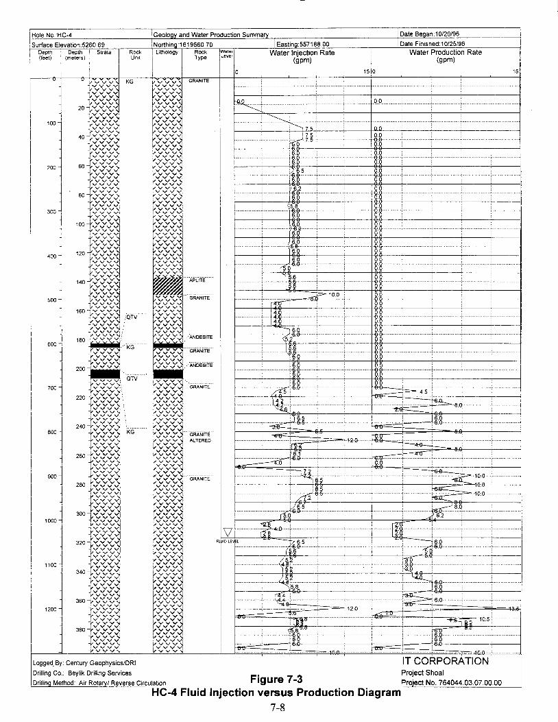
6.2 001··············,··············1·6.G- -00·········· .
60 00
6:0·:&0
.n
Water Production Rate(gpm)
······m····~·~·
:::=- 4.5
•
! Date Beoan:10/20/96
!Date Finished: 10/25/96
0.0
150
·f············ ..·····~&g·
!-.··-------t--.-!
0.0....... -00··
0.0
0.0.......... -00·····
0.0
00.............. -0.0········· ; .0.0
0:0.............. -00··
00
0:0............. -00····
00
··········f-········'····4U·····················f-·····-rn·
.........+ r!f ' .
0:0
.+&0 >I1!
.......................................~~&O .
0:0. -0.0······0.0
~7500
.......:;a~ ....(5.6
·······················~r~··
~.~...
...........~.4:0.. ~.: .
............In···16.0
1···············:···········~..--i,U ... ············11"0
I · ,..·· <.,~~y .T52
I··············;····~:.;.~'rH .j .
1············;········,/'4:..·~12...."\15.8
6:01··············,·····/.!·····.7.
5-c:-6·G-·:
14:01···············,·····+Its .
6:01···············,···············I-6.G-····
6.0
1 5 61 , llt~·
1 : , l..'-'i7"?~ii~···· ..•............ ·f··· ;. ,.: ~.+OG- .
1................•............1:""':%8...'(5~
I···············:··············\it~ .8"8.60 00
1 , I"tk· ····· : ·········f ~ ~·8.G
1···············:············.. ·'···d·····?2..-'·!U ····,·f ,... ~":.T.1:.,..._.._.._.-'--:="·+O.G-··
1 : 0~.~~... •~8~:~ 2u •
r··········,············· I~l. . zl60 00
'~5 ~Of··········,···············f-6.G- -0.0··
§.Q 00
6:0 00I··········· •.. it-6.~ .. . -00··6~ 00
:5.8 0:01·············,···············I-6.G-·· ......•.......................... -0.0········· .
60 00
, , ;..~I.H ·Z8·········· .[fo 00
F IDLE L
I Geoloov and Water Production Summary
Northing:1619560.70 IEastina:557188.00
I
i Lithology Rock ~·~:r Water Injection RateType (gpm)
o
RockUnit
900
700
800
500
600
400
100
300
200
1000
1200
1100
Surface Elevation:5260.69
IHole No.:HC-4
Logged.By: Century Geophysics/DRI
Drilling Co.: Beylik Drilling Services
Drilling Method: Air Rotary/ Reverse Circulation Figure 7-3
IT CORPORATIONProject ShoalProject No. 764044.03.07.00.00
HC-4 Fluid Injection versus Production Diagram7-8

I19
I
I Spectra Gamma RayThorium
(cps)
IDate Finished: 10/25/96
IDate Began: 10/20/96
Spectra Gamma RayUranium
(cps)
:557188.00Litholog
I
-1 r v v KG vv20 -j ..... vvv vvr v v
vv~40 ~
""';vv V VVil'vv VV
60 J.... vv ..... VV:'vv VV
80 j 20-'rVvVv~ "'","'vi100 j
i-v.....v",'Q :""':VJ..J~vvvv'<J~ -{.vvvv'<J vVvVj
120 -] "'vv40 -{.
Vv
Vv1 '-vv
140 -j Jvv v
t~:~:j160 -j v v V '01-{.v.....vvvi
180 1 KVv! rvv60 -;.vvvvv vv
'001 IV v ..... vVv"'J220 "Yvv vVv"'JIVYV
1o'VV'\! vvl240 -t.vvvv~ vv ...
~VVI
260 80-+"'",""'.....1 v v 1~vvvvi
280 J -vv.....v.....'<J~vv
!VVl vv
.300 ~~vv "'vvivvv
r~~~l-"vv
320 1""'''"1100 Iv""'",""'.....340 j ..... vv-..;
~<v:!VVVI360 tv:v:~
vv
380 ~vv
:v""1 vvvvvv
400 -i 120ivvvvltv"'",""'VI
420 1 l .....vvv.....
'-.fvv
I''''''''"1440 -] -l.....vvvvAPLiTE··
460 j IoOVV\i
140 1 ""' ''" 1' vv480 l.vvvvl
'vv v GRANiTE500 -1
-rvvvv1 (vVv~vv520 ~
"vv vv
540160--Jrv.....v....."",
'OTV ~vvvv""'vvv v v J
560 j!"vv : iVy .....~v v v 'v v
580 ~il'VV :' t:-"vvvvJ-:vvv:!"'vv t1vv.....""'J "ANDEsiTE180--'vvv:
600 i -KG n: D~~.620 -l -{.vvvv,;,
~vvGRANiTE·
vv'\l vv640 1 -{.VvVvVI !"'vv
200 -lv v,;,vv .·ANDEsiTE·
660 1vv
680 -1~vvvvv
OW~vv
700 ~vv GRANITE··Ivv .....
C--v vrvv vv
720 220 i:.....:.....: tyvVVv
740 ~ .,..vv~ rv vv~v v v vv
760 '
r~~lvv
780 ~vv
~vv VVIV""'''''' VV
800 -l 240 -t v v vvvvv rv.....v..... '---GRANITE'-~vv
820 J :vvv
VVl~vv
~:::: ALTERED840 1
IvvV'-"VV!VVVI
260-Y v v '\l ~vv860 ~ 1vvvvl
vv
880!vVV' ~v~v~.YvvIVVV'
'v V ~900 -1 .Y V V
~~~""."'VVI'vv
:~~280ivvv
lvvvvv'v V""vvv
960 -fvVVVy ~~~1980 1 .vv
1000 ~ 300 1.vV'vV''<J vvvv
jvvl.vv V'v
v l vv
tvvvv~vv
1020 -j vvvv
JV
1040~ jVVVI vv320 ,vvvv~ "'vv F UID LE
1060, '-vv rv~v~., i-vvvv""<J vv1080 -.1 iJ-J-
1vvvv
1100 ~ vv'-vv vv
1120 340~vVV r' vv vv~vvv vv
1140 ~ 'v v VV~iVV V vv
1160'v v vv
-I, v v v vvr v v vv1180 -1 360l'Vvvv1 vv
1200 jVV
-i,vvv..."v vv
t v vJV v"1 vv
1220 j ir.r.: ~vvvv~vv~ vv
1240 vvv vv3801vVvVv t v v
1260 j Tvvv.....v ~vvvv1280 -j vv
..... vv vv-J.vvv vv
vv vv
Depth i. Depth '. Strata 'I Rock(feet) ,meters) Unit
Surface Elevation:5260.69
Hole No.:HC-4
ILoggeq By: Century Geophysics/DRI IT CORPORATIONDrilling Co.: Beylik Drilling Services . Project ShoalIDrilling Method: Air Rotary/ Reverse Circulation Figure 7-4 Project No. 764044.03.07.00.00
HC-4 Geophysical Log Traces of Spectra Gamma Ray7-9
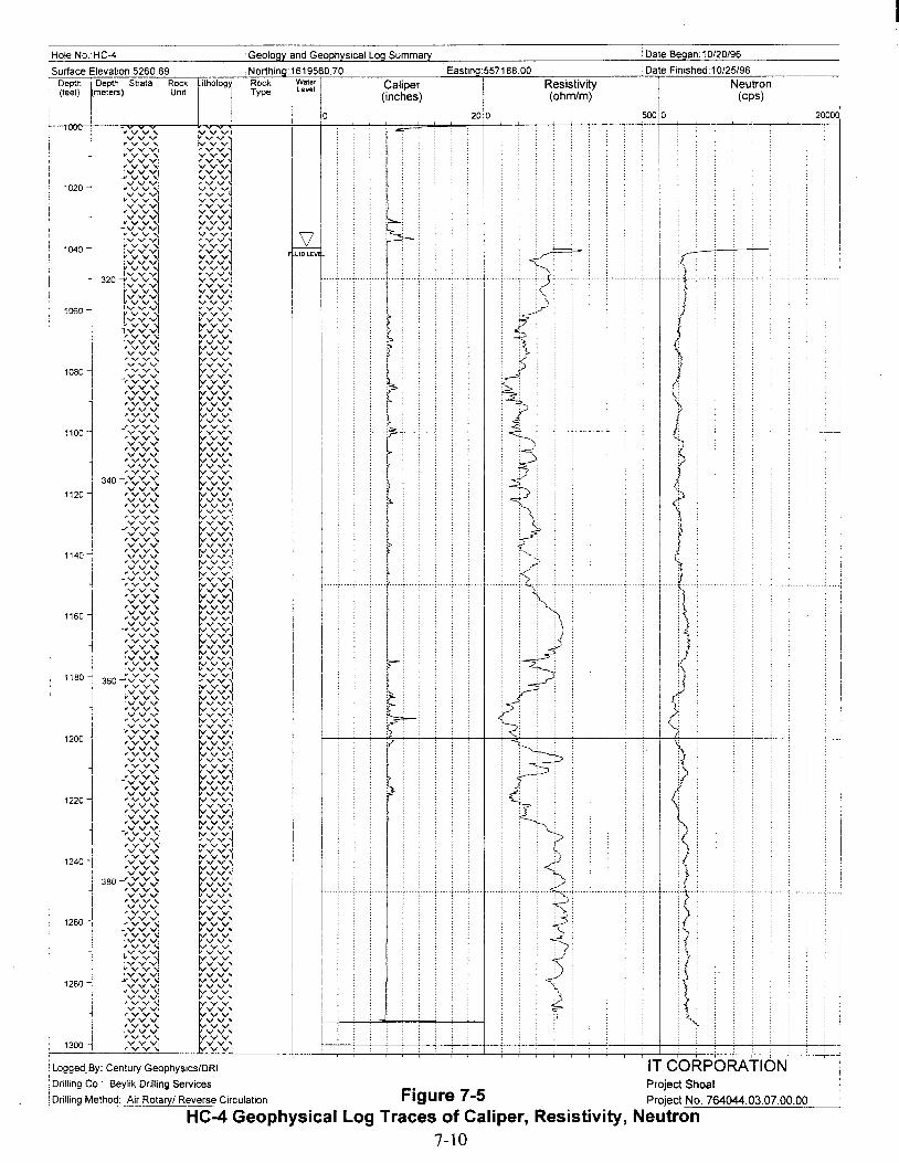
Geology and Geophysical Log Summary'Hole NO.:HC-4
Surface Elevation:5260,69Depth lDepth :"" Strata Rock(feet) Imeters) Unit
i i
Lithology
, I
Northing: 1619560,70
Rock Water IType Level
o
Caliper(inches)
iEasting:5571 66.00Resistivity(ohmlm)
200
:Date Beqan: 10/20/96
Date Finished 10/25/96Neutron
(cps)
500 0
I
2000(1
i
1020
1040
1060
1080
~100
1120
1140
1160
1180
1200
1220
1240
1260
1280
1300
;;~;>
<)
(
?
:Logged.By: Century Geophysics/DRI IT CORPORATION I:Drilling Co.: Beylik Drilling Services • Project Shoal I!Drilling Method: Air Rotary/ Reverse Circulation Figure 7-5 Project No. 764044.03.07.00.00 ----l
HC-4 Geophysical Log Traces of Caliper, Resistivity, Neutron7-10
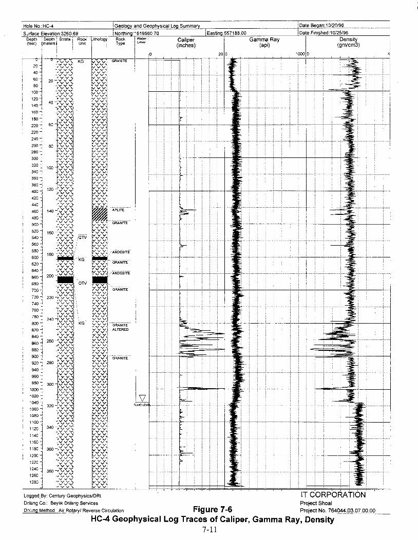
Hole NO.:HC-4 Geology and Geophysical Log Summary Date Began:10/20/96
iJ
I
=
IDensity
(gmlcm3)
Date Finished:1 0/25/96
10000
•
Gamma Ray(api)
~~
"-----i-----'------c-----:---,.---+-----'-,...=lr~----'-"_____1
-., ~-
....
l
200
'Eastino:55718800
5;;::_
-~-
:0=:---.;::::>!" •
Caliper(inches)
o
f·····, ....;....·:.....~\oc:i=; .....,.....c.... ·,··t..·
f.... -;.... ·,..·..,....+·.. ·,· ..·,....·,····,·····,····t·····
f.... ·:.... ·,..·..;..·+ .. ··:· ....,.... ·, ....·;.. ·..:..·..t ....
~
..... '"-:-- It:.~--'---'---j
.:;; ~
I·.. ··:· ..·..:..·.. ,··..-f- :· , ·, ·: ·t ~~., , : , , " : , + , , , , <~., Eoc·,.· ;· ; ·1
~
.:;;;iiI "
~1·..··:·····,·····,···+·..·:· , ·,·..··;· :..·..1 'Ij~.; : : ; : , : : + : ; : ; , .0:;
j
5L'Iu,o ""'1'- ....:.....,... ·,····r·····,·.. .... ···:·· ...;.....;.... t..~ rI
I
Rock I Wale,Type I Level
I
Northing:1619560.70Lithology
I i
I !
KG800 1,820 1840 -j
860~880 :
900~920 -j940~960,980.:1,
1000 -1020 11040 11060 -i.,1080 j1100 -i1'20 ~1140 -]
1160 -j1180 ~
1200 -j1220 -:I1240 J1260 ...;.,1280 -1
j
Depth I
r
Depth '. Strata i Rock(feet) meters) 'Un,t
ii I
:Surface Elevation:5260.69
IT CORPORATIONProject Shoal
Figure 7-6 Project No. 764044.03.07.00.00
HC-4 Geophysical Log Traces of Caliper, Gamma Ray, Density7-11
Logged.By: Century Geophyslcs/DRI
Drilling Co.: Beylik Drilling Services
Drilling Method: Air Rotaryl Reverse Circulation
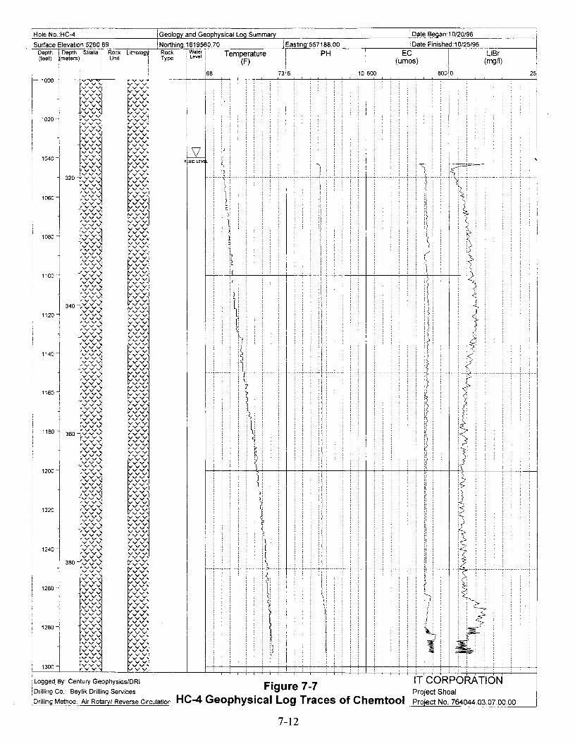
ii
25'
:
LiBr(mgtl)
)
. :
IDate Began:10/20/96
8000
IDate Finished:10/25/96
EC(umos)
10600
•
!Eastina:557188.00
Temperature(F)
7
••
Rock IWaterIType Level
I 168
IGeoloov and Geophysical Loa Summary
!Northing:161956070ithology
I
!
1180
1120
1160
1240
1200
1060
1140
1100
1300
1220
1080
1040
1280
1260
1020
ISurface EleYation:5260.69
IHole NO.:HC-4
I
Depth Depth i Strata I Rock(feet) meterSj I Unit
I
Logged.By: Century Geophysics/DRI
Drilling Co.: Beylik Drilling Services
Drilling Method: Air Rotary/ Reverse Circulation
Figure 7-7HC-4 Geophysical Log Traces of Chemtool
IT CORPORATIONProject Shoal
Project No. 764044.03.07.00.00
7-12
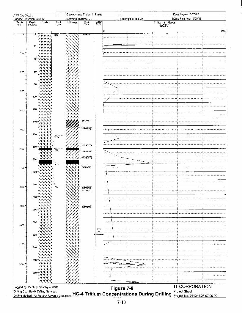
,
8000
IDate secan. 10/20/96
IDate Finished: 10/25/96
Tritium in Fluids(pCi/L)
iEastinQ:557188.00
o
IWaterLevel
i Geology and Tritium in Fluids
INorthina:1619560.70
ILithology Rock
I Type
iI
RockUnit
Depth ! Depth I Strata(feet) I (meters)
I i
Surface Elevation 5260.69
~-------------'-----------------------------r-----------,
iHole No :HC-4
..·f··· ..·..·..· · · ·;- · · · · · ·, · · ·..· ;- :··· ·..·..· ·· ·· ··1
.......................................................... I
IT CORPORATIONProject Shoal
Proiect No. 764044.03.07.00.00
:
<,........ .>.. : · ;-· · · ·..· ·..·.. ·: .. ·· ·..· · · ··c , I
..· 1 · ·· ·.. ·: · · ; , · ·.. , · · ··· · · 1
\\1·· · ··; · · · · , + :..................... 1
\
\
/
......... \
... \ ; , · :· · ·: · ·..· ·1
....... \ ,.... • ,................... 1
.... (
)
~ .
I=1·· ..· · ·; ·· · ·· ..·.., ·..· ·..·..·..c · · ·..· ·..·..·· ..· ·· j
"'""., : , ' ,.......................... 1
-----=-=; , , ,....................... 1
"'..."<; , : ··..· ·; · · ·, .. · · · .. ·1
!
F UIDlEVEL
Logged.. By: Century ~eOPhySiCS/DRI Fig ure 7-8Drtlling Co.: Beylik Dnlling Services HC 4 T " . C . D" D "II"Drilling Method: Air Rotaryl Reverse Circulation .._..:.__....E'_!'~m oncentratlons ._~~I':'~_.. ~~ ..~!!
7-13

iHole NO.:HC-4 iGeology and Well Construction Summary iDate Began:10/20/96
:SurfaceElevalion:5260.69 iNorthina:1619560.70 IEaslina:557188.00 IDate Finished:10/25/96
IDepth 1 Depth Istrat. i Rock Lith Rock ! Waler I Caliper
IWell Construction
I(feet) I (meters) I I Unit Type I Level I (inches)
I i I I 201I I 0
Y;"vJ KG ;""v GRANITE ;;:."'; ~-~20 ~ v t ---'1_- ~ BOREHOLE 12.0" 0-103.0Vv~ ..... v:
::.-~1-vv '1~ v 1
.i-> ---- ~--.:40~vJ ::.-~
:~ ~ lVv
'1......... - ...._.~
~-=20 vv'1"vd ::-_~ .---vv'1 'v
::-_~ \:CEMENT""100 1-vv'1 ~ v 1 .. --··1_-w'11 -ivVj~~'1::1 rv~ :
401'vv
""'"-l V Vi 'v'160
!'v, l'v'1-j..vv'1t'v'1 ' CASING 8.625" 0-103.0
180 J v '1
60+~~j Y.....'1200
rvj220 tv
v.
240 ~yv ~
~~EII
·fv'1260 80 vv'q 'v
""-vvv"1 'v280 ~Vy1 ·j.,vv':1
II~Ol .j.,vv'1 r~j320 100-i.-v
....."q340
±~~jrvl
II.... '1
360J,vv ~~'1
~j ''"f~~r''''
II~vJ400 ""vvl
II420 ::1 l,VJ
rv :
MOl 140-(v'1 ~"'APLiTE'" "",:460 v ':1 P-
I480 tv~'1 ~"-GRANiTE'500 }Vv~ CASING 5.5" 0-1013.0
IIvvv~
tvj520 N'¥
1601-vviON l,vJ
540 J tv..... rvl
IIt'v'1560 I t,vv'1 : ....VI :;;:-
580 1 lV~:
~rvx ANDEsiTE
,I600 --j 180~ ---.+._--
620 -l v, KG "GRANITE'IiI
640 -j
~,,':vi
v~
~ANDE'siTE' 'I
660 -I 200 ="I.I
680 ) ON-..-.
~ BOREHOLE 8.0" 103.0-1303.0
I{vv-.:(l.-vV! GRANiTE' ---- f--
700 'vdv ~. v720 j 220 tVv'1 r v
I740 v....."1 \ rvJrvJ
I.j.,v VI . I760 --I v,
I
Iv'" .vll -v v "'i "".....,
780 1 240..(..vv'q .vJtvJ-...... ==
800 J fV1KGv,• va GRANITE ~vv:
820 v, v ALTERED.,..vv'1 rv
Ii840 IV ........ rvl
Ii8601 260 ...... V~ .... ~!::j rvt'v
880 '1 ;.,..~
900 J ~~j 'GRANITE"920 280 I ~Vj tVJ940 1 1v
vl,vJ.r v ~
}vv'1 .vl960'" r-)1.,
i V V1
tj~j300 "'vv'l
1000 1~~~ 'vv1020 (,v V1040 iV~~ rv =v
UID LEVI L320 v'" 'v1060 vVJ tv
.... :.....
r v ~ .F-1080 -,
r~1 L·1 ~~v1 e-1100~
340 {v~'1 'v1120 ""'"1140 l -j..vv '1 tvl
J v 'q tv'11160 1 JvvVl r vVi
{V' r'v1 I.-1180 ~ 360 vv':.1
~~~~- / FILL 1294.0-1303.0I
yVV~1200
1220 1{-vv'::l
~
1240 j tVv'1 t~
38°IVv'1 ...Lvv~ rV1260 ~ r-vJ
!1280 .j,.~~1 t--'(,I rv . ---..... _~ .. '-~"'."'.'" . .......... ........ ~.. -
Logged. By: CenturyGeophysicslDRIFigure 7-9
IT CORPORATIONDrilling Co.: BeylikDrillingServices Project ShoalDrilling Method Air Rotary/ Reverse Circula.!iO!!....HC-4 Subsurface Well Completion Diagram Project No. 764044.03.07.00.00
7-14

Well Coordinates(State Planar NAD 27)N: 1619615.283E: 557466.095
Clamp/ Landing Plate
Well Pad
1.22 m x 1.22 m x 0.15 m(48 in x 48 in x 6 in)Reinforced with a 15.2-cm x 15.2-cm(6 in x 6 in) wire mat
I•1.22 m
(48 in) • IProtective Casing
32.38-cm (12 3/4 in) od0.32-cm (.125 in) wall
Surface Casing
21.91-cm (8 5/8 in) od0.48-cm (.188 in) wall
Intermediate Casing
1397-cm (5 1/2 in) od12.70-cm (5.0 in) id
Data Logger Access Tube
3.81-cm (1 1/2 in) conduit
Shelter for Data Logger
60,96-cm (24 in) diameter pad
pl.mJfie.....
Profile Vi~w
Figure 7-10HC-4 Well Head Completion Diagram
~ ~ Lockable Lido
.~cor-- 0 32,38-cm (12 3/4 in)od Protective Casing,..: -,;
Cap 13.97-cm (5 1/2 in) od ThreadedE .~ur-- 0
N Lri~
Intermediate Casing with 13,97-cm
E (51/2 in) od Threaded Couplingu .~
'{.!. LOr--,..: cD
~
Data Logger Access Tube
E .~0
o-c LOC") N.,.; Lri
Q <~
.s IE
LO
IIIo
Nr--
I Concrete PadLO .,.;en I -'I-- .. .. I '", .:... ', :".. ", .Ground Surface E : .',=.: ~.~ ~:. : •... :a.... : e-,o .s A' :'J".', I
-', .:.. " :'.. ',Elevation "'" 0 .v : .. .:."-:' I:~:.:~/~.~:.~.
N:'J,,",1603.46 m Lri cD A' .' '
~ ':':,' :...... :. I :!'-:.: t-:.:....(5260,69 ft)A' 'A' .. " .
It>..\\Y!'A' ovc« I I ~ v ,. '11.\ \YII.\\Yf),\\Y 1\\\". ,.
i< - - ,{- / .... - /
~~Surface Casing
Clamp/Landing Plate
;g;ro
No~l- ---...... ......
7-15

Table 7-1HC-4 Lithium Bromide Concentrations
Date Time Depth Sample Cone. Sample Temp
mm/dd/yy (24 hrs) (ft) (mg/L) (Co) Sample Source Analysis By10/22/96 0630 NA 20.3 24.0 aces (20 mg/L) R. Peterson10/22/96 0540 NA 28.7 19.5 Water Truck R. Peterson10/22/96 0540 675 27.1 22.0 Discharge Line (DL) R. Peterson10/22/96 0605 NA 26.7 20.9 WT R. Peterson10/22/96 0605 690 25.6 22.6 DL R. Peterson10/22/96 1100 803 27.5 22.4 DL JWurtz10/22/96 1105 NA 19.9 25.3 cccs (20 mg/L) JWurtz10/22/96 1106 NA 27.7 21.7 WT JWurtz10/22/96 1108 823 27.4 21.4 DL JWurtz10/22/96 1135 NA 21.9 24.8 WT JWurtz10/22/96 1145 843 23.2 25.1 DL JWurtz10/22/96 1120 863 20.4 25.3 DL JWurtz10/22/96 1320 NA 20.0 25.0 occs (20 mg/L) JWurtz10/22/96 1220 875 22.0 25.1 DL JWurtz10/22/96 1300 900 22.0 25.1 DL JWurtz10/22/96 1335 NA 29.0 25.4 WT JWurtz10/22/96 1330 920 35.4 25.2 DL JWurtz10/22/96 1435 NA 27.7 25.2 WT JWurtz10/22/96 1530 NA 20.3 25.1 occs (20 mg/L) JWurtz10/22/96 1430 940 32.2 25.5 DL JWurtz10/22/96 1530 960 30.3 25.5 DL JWurtz10/22/96 1630 980 28.8 25.3 DL JWurtz10/22/96 1715 NA 28.5 25.6 WT JWurtz10/22/96 1715 1000 29.5 25.2 DL JWurtz10/22/96 2100 NA 19.9 25.5 occs (20 mg/L) AM.Welcher10/22/96 1810 1025 30.3 25.0 DL AM.Welcher10/22/96 1830 1043 31.2 25.2 DL AMWelcher10/22/96 2030 NA 34.6 25.0 WT AM.Welcher10/22/96 2030 1065 28.3 25.4 DL A.MWelcher10/22/96 2105 1085 30.0 25.4 DL A.M.Welcher10/22/96 2350 NA 20.0 25.3 occs (20 mg/L) AMWelcher10/22/96 2130 NA 33.1 25.3 WT A.MWelcher10/22/96 2130 1105 23.1 25.3 DL A.MWelcher10/22/96 2235 1125 30.6 25.3 DL A.MWelcher10/22/96 2315 1145 30.7 25.3 DL A.M.Welcher10/23/96 0000 1165 29.1 25.3 DL AMWelcher10/23/96 0010 NA 19.8 25.3 occs (20 mg/L) AMWelcher10/23/96 0345 NA 20.5 26.5 occs (20 mg/L) R. Peterson10/23/96 0050 1185 28.9 26.0 DL R. Peterson10/23/96 0225 1200 30.6 26.1 DL R. Peterson10/23/96 0325 NA 33.5 25.8 WT R. Peterson10/23/96 0325 1205 28.9 26.0 DL R. Peterson10/23/96 0425 1190 24.7 25.7 DL A.MWelcher10/23/96 0600 NA 19.9 26.1 occs (20 mg/L) A.M.Welcher10/23/96 0500 1205 24.7 26.2 DL J. Wurtz10/23/96 0600 1223 36.4 26.1 DL J. Wurtz10/23/96 0700 1243 35.5 26.0 DL J. Wurtz10/23/96 0800 1243 33.6 25.8 DL J. Wurtz10/23/96 0900 1263 30.8 26.0 DL J. Wurtz10/23/96 1130 NA 20.2 26.0 occs (20 mg/L) J. Wurtz10/23/96 0920 NA 30.3 26.1 WT J. Wurtz10/23/96 1000 1283 21.0 24.3 DL P. Gallo10/23/96 1000 NA 46.4 22.5 WT P. Gallo10/23/96 1220 NA 34.9 22.0 WT P. Gallo10/23/96 1220 1295 40.5 23.9 DL P. Gallo10/23/96 1315 NA 39.0 26.0 WT J. Saavedra10/23/96 1315 1303 38.8 25.1 DL J. Saavedra
7-16

.......:JI......
.......:J
Table 7-2HC-4 Water Level Measurements
Depth to ElevationWell Name Date Fluid (tt) (tt) Notes
HC-4 23-0ct-96 1045.8 4214.89 Water level obtained immediately after development by IT using a solinst tape down drill pipe.
HC-4 24-0ct-96 1040 4220.69 Fluid level picked off Century Geophysical neutron log, measured from GL.
HC-4 24-0ct-96 1040 4220.69 Fluid level obtained from Century Geophysical temperature log using a datum of GL.
HC-4 24-0ct-96 1044.6 4216.09 Fluid level to ground surface. Measurement obtained by DRI using the Chemtool.
HC-4 01-Nov-96 1044.91 4215.78 DRI measurement of water level using downhole video camera.
HC-4 07-Nov-96 1041.96 4218.73 Water level was obtained by DRI using the EC Temperature tool. Meas. from GL.
HC-4 13-Nov-96 1040 4220.69 Approximate water level obtained with the DRI video camera. Measured from GL.

-....lI.......
00
Table 7-3HC-4 List of Geophysical Logs
Geophysical Date Log Bottom Log Top LoggingWell Name Log Logged (tt) (tt) Company
HC-4 3-Arm Caliper 10/24/96 1292.90 4.70 Century Geophysical
HC-4 Density/Resistivity/Neutron/Neutron Porosity 10/24/96 1294.00 0.00 Century Geophysical
HC-4 Deviation - magnetic 10/24/96 1294.40 3.30 Century Geophysical
HC-4 Spectra Gamma Ray (K, U, Th) 10/24/96 1292.50 3.10 Century Geophysical
HC-4 Temperature 10/24/96 1294.40 0.00 Century GeophysicalHC-4 Acoustic Borehole Televiewer 10/24/96 1289.98 1034.94 Century GeophysicalHC-4 Chemtool 10/25/96 1295.00 1045.00 DRIHC-4 Downhole Video Camera 10/23/96 1043.00 0.00 DRI
Note: Calibrations and repeat sections were performed per contract specifications.

Table 7-4HC-4 Summary of Subsurface Investigation Samples
Sample NumberDate
Location Sample Type Depth (ft)COCa
CommentsCollected Number
PSCOOO01 10/2/96 HC-1 Cuttings 930 519811 Cuttings sample collected at HC-1 during drilling.
PSWOOO03 10/4/96 HC-1 Groundwater 920 519812 Groundwater sample from HC-1 Well Development...Fuli Lab QC
PSWOOO04 10/4/96 HC-1 Groundwater (dup) 920 519812 Duplicate of sample PSWOOO03
PSWOOO05 10/4/96 HC-1 Water (QC) NA 519812 Equipment Rinsate sample
PSWOOO06 10/4/96 HC-1 Water (QC) NA 519812 Field Blank sample
PSFOOO01 10/5/96 HC-1 Discharge Fluid NA 519816 Composite sample collected at HC-1 Sump #1
PCXOOO01 11/3/96 HC-1 2nd Discharge Fluid NA 519820 Additional fluids discharged into HC-1 Sump #1, 2nd composite sample collected.
PSCOOO02 10/16/96 HC-2 Cuttings 1253 519813 Cuttings sample from HC-2 taken during drilling.
PSWOOO07 10/21/96 HC-2 Groundwater 1173 519814 Groundwater sample from HC-2 Well Development.
PSFOOO03 10/20/96 HC-2 Discharge Fluid NA 522037 Composite sample collected at HC-2 Sump #1.
PSCOOO03 11/5/96 HC-3 Cuttings 1255 519822 Cuttings sample from HC-3 taken during drilling.
PSWOOO08 11/14/96 HC-3 Groundwater 1104 519823 Groundwater sample from HC-3 Well Develop. Waiting on results.
PSFOOO05 11/12/96 HC-3 Discharge Fluid NA 519824 Composite sample collected at HC-3, Sump #1.
PSCOOO04 10/23/96 HC-4 Cuttings 1250 519817 Cuttings sample collected at HC-4 during drilling.
PSWOOO09 11/7/96 HC-4 Groundwater 1130 519819 Groundwater sample from HC-4 using a discrete bailer.
PSFOOO07 10/24/96 HC-4 Discharge Fluid NA 519818 Composite sample collected at HC-4, Sump #1
'Chain of Custody
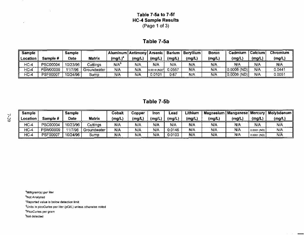
-....JI
No
Table 7-5a to 7-5fHC-4 Sample Results
(Page 1 of 3)
Table 7-5a
Sample Sample Aluminum Antimony Arsenic Barium Beryllium Boron Cadmium Calcium Chromium
Location Sample # Date Matrix (mg/L)a (mg/L) (mg/L) (mg/L) (mg/L) (mg/L) (mg/L) (mg/L) (mg/L)
HC-4 PSCOOO04 10/23/96 Cuttings N/Ab N/A N/A N/A N/A N/A N/A N/A N/AHC-4 PSWOOO09 11/7/96 Groundwater N/A N/A 0.0018 (NO)' 0.0557 N/A N/A 0.0006 (ND) N/A 0.0441HC-4 PSFOOO07 10/24/96 Sump N/A N/A 0.0101 0.67 N/A N/A 0.0006 (ND) N/A 0.0051
Table 7-5b
Sample Sample Cobalt Copper Iron Lead Lithium Magnesium Manganese Mercury Molybdenum
Location Sample # Date Matrix (mg/L) (mg/L) (mg/L) (mg/L) (mg/L) (mg/L) (mg/L) (mg/L) (mg/L)
HC-4 PSCOOO04 10/23/96 Cuttings N/A N/A N/A N/A N/A N/A N/A N/A N/AHC-4 PSWOOO09 11/7/96 Groundwater N/A N/A N/A 0.0146 N/A N/A N/A 0.0001 (NO) N/AHC-4 PSFOOO07 10/24/96 Sump N/A N/A N/A 0.0103 N/A N/A N/A 0.0001 (NO) N/A
aMilligram(s) per liter
bNot Analyzed
CReportedvalue is below detection limit
dUnits in picoCuries per liter (pCi/L) unless otherwise noted
·PicoCuries per gram
INot detected
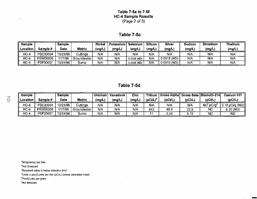
-....)Itv
Table 7-5a to 7-5fHC-4 Sample Results
(Page 2 of 3)
Table 7-5c
Sample Sample Nickel Potassium Selenium Silicon Silver Sodium Strontium Thallium
Location Sample # Date Matrix (mg/L) (mg/L) (mg/L) (mg/L) (mg/L) (mg/L) (mg/L) (mg/L)
HC-4 PSCOOO04 10/23/96 Cuttings N/A N/A N/A N/A N/A N/A N/A N/AHC-4 PSWOOO09 11/7/96 Groundwater N/A N/A 0.0028 (NO) N/A 0.0015 (NO) N/A N/A N/AHC-4 PSFOOO07 10/24/96 Sump N/A N/A 0.0028 (NO) N/A 0.0015 (NO) N/A N/A N/A
Table 7-5d
Sample Sample Uranium Vanadium Zinc Tritium Gross Alpha Gross Beta Bismuth-214 Cesium-137
Location Sample # Date Matrix (mg/L) (mg/L) (mg/L) (pCi/L)d (pCi/L) (pCilL) (pCi/L) (pCi/L)
HC-4 PSCOOO04 10/23/96 Cuttings N/A N/A N/A N/A N/A N/A NOt pCi/ge 0.18 pCi/g (NO)HC-4 PSWOOO09 11/7/96 Groundwater N/A N/A N/A 643 48.9 22.8 NO 6.32 (NO)HC-4 PSFOOO07 10/24/96 Sump N/A N/A N/A 11 5.24 5.15 NO NO
aMilligram(s) per liter
bNot Analyzed
CReported value is below detection limit
dUnits in picoCuries per liter (pCi/L) unless otherwise noted
·PicoCuries per gram
'Not detected
-
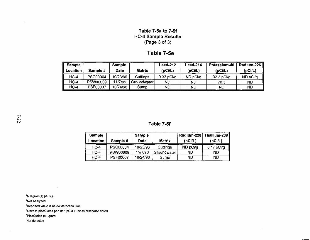
-.....lItvtv
Table 7-5a to 7-5fHC-4 Sample Results
(Page 3 of 3)
Table 7-5e
Sample Sample Lead-212 Lead-214 Potassium-40 Radium-226Location Sample # Date Matrix (pCi/L) (pCi/L) (pCi/L) (pCi/L)
HC-4 PSCOOO04 10/23/96 Cuttings 0.32 pCi/g NO pCi/g 32.3 pCi/g NO pCi/gHC-4 PSWOOO09 11/7/96 Groundwater NO NO 70.3 NOHC-4 PSFOOO07 10/24/96 Sump NO NO NO NO
Table 7-5f
Sample Sample Radium-228 Thallium-208Location Sample # Date Matrix (pCi/L) (pCi/L)
HC-4 PSCOOO04 10/23/96 Cuttings NO pCi/g 0.17 pCi/gHC-4 PSWOOO09 11/7/96 Groundwater NO NOHC-4 PSFOOO07 10/24/96 Sump NO NO
aMilligram(s) per liter
bNot Analyzed
CReportedvalue is below detection limit
dUnits in picoCuries per liter (pCi/L) unless otherwise noted
ePicoCuries per gram
'Not detected

8-1
8.0 Fluid Management
8.1 Summary of Fluid ManagementFluid was managed during the Shoal Project through an FMP. This strategy provided guidance
for the management of fluids generated during well drilling and construction activities. The FMP
(DOE/NV, 1996c) used a fluid management decision strategy based on process knowledge and
verification of process knowledge through laboratory analyses and field screening methodologies.
One single-lined and one double-lined sump were constructed at each drill pad. The single-lined
sumps (Sump #1) were used to contain uncontaminated fluids. The double-lined sumps (Sump
#2) were built to contain contaminated fluids. The double-lined sumps were never used. Tritium
levels in the drilling fluids did not even approach the Nevada Drinking Water Standard (NDWS)
(NRS 445, 1996 and NAC 445A, 1996) of 20,000 picoCuries per liter (pCi/L). All fluids
generated during drilling of the four wells were analyzed for lead and tritium. Tritium was
monitored on an hourly basis, while lead was monitored every eight hours. Tritium was only
detected in background concentrations, and lead results were at nondetectable levels. A fluid
sample was collected from a sump and sent to an off-site laboratory for analysis at the completion
of drilling operations when fluid from downhole was no longer being discharged into the sump.
8.2 Source Water for DrillingSource water for drilling came from water supply Well HS-1, located east of the project site in
Fairview Valley. Water from Well HS-1 was sampled and submitted for analysis by Quanterra
Labs. The water from this well was found to be below threshold limits for analytes as defined in
the NDWS (NRS 445, 1996 and NAC 445A, 1996).
8.3 Sump ConstructionOne single-lined and one double-lined sump were constructed at each drill pad according to the
specifications established in the FMP for the Shoal Project Area (DOE/NV, 1996c). For details
of sump construction, see sump construction diagrams, Figures 8-1 and 8-2, included after the
text. Each sump that was used to contain fluids also contains a wildlife escape ladder. The sumps
are completely surrounded with orange construction fencing. In addition, flagging was strung
across the sumps to discourage birds from landing in the sumps.

8-2
8.4 Disposition of Fluids and Current Status of SumpsDrilling fluids from Wells HC-1, HC-2, HC-3, and HC-4 were discharged into their respective
sumps: HC-1 Sump #1, HC-2 Sump #1, HC-3 Sump #1, and HC-4 Sump #1. When drilling
operations were completed at each well, a composite sample was taken from Sump #1 for
laboratory analysis. An “ER Fluid Disposition Tracking Form” was also filled out at this time to
track the amount of fluid that was discharged into each sump. These forms are provided for
reference at the end of this section as Tables 8-1 through 8-4.
A letter dated December 4, 1996, to B. Bangerter (DOE Underground Test Area Subproject
Manager) from P. Gretsky (IT Offsites Project Manager), indicated that all fluid management
results for each of the sumps were below five times the NDWS. Therefore, the fluids could be
released via overland flow.
At the completion of hydrologic testing and Shoal Mud Pit remediation, all but two of the drilling
sumps were closed. Approximately 600 gallons of water from the sump at HC-1 were discharged
to the ground or used for dust control. All but two sumps were closed in place. One sump
located at HC-3 and one at HC-4 are still used for fluid management during hydrologic testing of
these wells. The liners were removed from the closed sumps and shipped to the NTS for disposal.
The cuttings were buried in place and the areas graded. The sumps associated with HC-3
alternate drilling location were never used and therefore never lined. These sumps were pushed in
and the area was also graded (IT, 1998).

Apron
25 feet
I
r+---+---L--/ ~~I---_
50 feet
Top View
¢~'---------~~SlopeSideViElw
Apron
Ground 1--------..1Surface
Inset View-------------- ----
Note:
Liner is a 55- by 55-foot flat sheet of 35-mil (0.035-inch) Hypaton'"
cooI'llNoo~ L.... ..J
Figure 8-1Diagram of Single-Lined Sump Construction
8-3

15 feet
Apron
4"PVC
Inspection pipe
40 feet
Top View
Inspection Pipe
Side View
Geotextile
Apron
Fill
Ground I--------~
Surface
Inset View
Note:
Liners are 55- by 55-foot flat sheet of 36-mil (0.036-inch) HypalonM
Leak detection trench filled with +1/2 - 3/4" gravel.eno<'IlNoo~L.- _
Figure 8-2Diagram of Double-Lined Sump Construction
8-4

Table 8-1Well HC-1 ER Fluid Disposition Status Reporting Form
Site Identification: HC-1Site Location: Shoal Proj. Churchill Co. NV. ,Site Coordinates: N: 1621,993.0 E: 557623.4 approx.
Well Classification: Near FieldIT Project No: 764044.03.07.00.00
Report Date: 10/27/96DOE/NV Project Manager: Janet WingIT Project Manager: Paul Gretsky
IT Site Representative:IT Waste Coordinator:
Jeff WurtzTerre Maize
ell Construction Activity Activity Duration#Ops.D Wellays (A) Depth
(m)
From To Solids Liquid Solids liquid
Stage I: 9/26/96 10/2/96 7 286.5 15.84 56.79 0 0Vadose-Zone Drillin
Stage II: 1012/96 10127/96 3 409.34 5.97 14.29 0 0Saturated-Zone Drillin •
000I
Stage ill: 10/2/96 10127/96 4 409.34 0 45.39 0VIInitialWell Develo rnent"
Stage IV: na na na na na na na naFinal Develo ment
na na na na na na na na
Cumulative Production Totals to Date:14
21.81 116.47
(A) Operational days refer to the numberof days that the drill rig was in operation during at least part of one shift.(8) Solidsvolumeestimatesincludecalculatedadded volume attributedto rock bulking factors.NA =Not Applicable; m =meters; m3 =cubic meters; AlP =Analysis In Process• Well reentered and deepened, duration spans both initial drilling and deepening efforts.
Tritium Curie Inventory: Sump #1 (lined) =Fluids at natural background Sump #2 (double-lined) =naTotal Device Capacities (rn"): Sump #1 = 219.0 Sump #2 = 219.0
Remaining Device Capacity (Approximate) as of 10/27/96 Sump #1 = 86.83 m3 Sump #2 = 219.0 m3
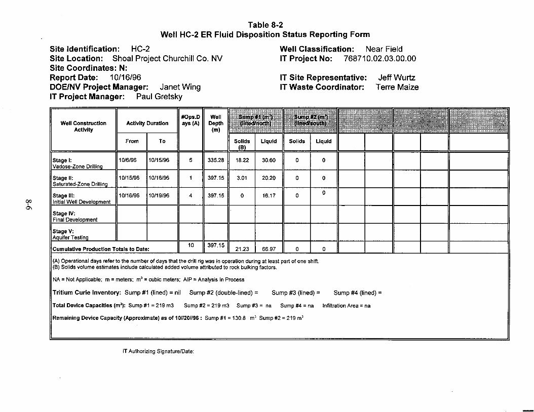
Jeff WurtzTerre Maize
IT Site Representative:IT Waste Coordinator:
Table 8-2Well HC-2 ER Fluid Disposition Status Reporting Form
Well Classification: Near FieldIT Project No: 768710.02.03.00.00
Site Identification: HC-2Site Location: Shoal Project Churchill Co. NVSite Coordinates: N:Report Date: 10/16/96DOE/NV Project Manager: Janet WingIT Project Manager: Paul Gretsky
#Ops.D WellWell Construction Activity Duration ays (A) Depth
Activity (m)
From To Solids Liquid Solids LiquidB
Stage I: 10/6/96 10/15/96 5 335.28 18.22 30.60 0 0Vadose-Zone Drillin
Stage II: 10/15/96 10/16/96 397.15 3.01 20.20 0 0Saturated-Zone Drillin
Stage iii: 10/16/96 10/19/96 4 397.15 0 16.17 0 0
00 Initial Well Develo mentI
0'1Stage IV:Final Develo ment
Cumulative Production Totals to Date:10 397.15
21.23 66.97 o o
(A) Operational days refer to the number of days that the drill rig was in operation during at least part of one shift.(8) Solids volume estimates include calculated added volume attributed to rock bulking factors.
NA =Not Applicable; m =meters; m3 =cubic meters; AlP =Analysis In Process
Tritium Curie Inventory: Sump #1 (lined) = nil Sump #2 (double-lined) = Sump #3 (lined) = Sump #4 (lined) =Total Device Capacities (rrr'): Sump #1 =219 m3 Sump #2 =219 m3 Sump #3 = na Sump #4 =na Infiltration Area =na
Remaining Device Capacity (Approximate) as of 1011201196: Sump #1 =130.8 m3 Sump #2 =219 m3
IT Authorizing SignaturelDate:

Table 8-3Well HC-3 ER Fluid Disposition Status Reporting Form
Well Classification: Near FieldIT Project No: 768710.02.03.00.00
Site Identification: HC-3Site Location: Shoal Project Churchill Co. NVSite Coordinates: N:Report Date: 11/09/96DOE/NV Project Manager: Janet WingIT Project Manager: Paul Gretsky
IT Site Representative:IT Waste Coordinator:
Jeff WurtzTerre Maize
#Ops.D WellWell Construction Activity Duration ays (A) Depth
Activity (m)
From To Solids Liquid Solids Liquid
Stage I: 11/3/96 11/5/96 3 329.18 17.97 36.13Vadose-Zone Drillin
Stage II: 11/5/96 11/9/96 5 397.15 3.26 74.42
Saturated-Zone Drillin
Stage III: NA NA 0 NA NA NA00 Initial Well Develo ment
I-...]
Stage IV:Final Develo ment
Cumulative Production Totals to Date:8 397.15
21.23 110.55
m3 Sump #2 = NA m3
(A) Operational days refer to the number of days that the drill rig was in operation during at least part of one shift.(8) Solids volume estimates include calculated added volume attributed to rock bulking factors.
NA =Not Applicable; m =meters; m3 =cubic meters; AlP =Analysis In Process
Tritium Curie Inventory: Sump #1 (lined) =All fluids discharged were at background levels Sump #2 ( not lined) =NA
Total Device Capacities (m3) : Sump #1 =219.0 Sump #2 =not lined
Remaining Device Capacity (Approximate) as of: 11/09/96 Sump #1 87.22
IT Authorizing Signature/Date:

Jeff WurtzTerre Maize
IT Site Representative:IT Waste Coordinator:
Table 8-4Well HC-4 ER Fluid Disposition Status Reporting Form
Well Classification: Near FieldIT Project No: 768710.02.03.00.00
Site Identification: HC-4Site Location: Shoal Project, Churchill Co. NVSite Coordinates: N:Report Date: 10/23/96DOE/NV Project Manager: Janet WingIT Project Manager: Paul Gretsky
Well ConstructionActivity
Activity Duration#Ops.D Wellays (A) Depth
(m)
From To Solids LiquidB
Solids Liquid
Stage I:Vadose-Zone Drillin
10/20/96 10122/96 2 318.39 18.75 24.98 o o
Stage II:Saturated-Zone Drillin
10122/96 10123/96 2 397.15 2.48 12.11 o o
10/23/96 10123/9600I
00
Stage III:Initial Well Develo ment
Stage IV:Final Develo ment
NA NA NA
397.15
NA
o
NA
2*
NA
NA
NA
NA
NA
NA
Cumulative Production Totals to Date:
NA NA
5
NA
397.15
NA
21.23
NA
39.09
NA
o
NA
o
(A) Operational days refer to the number of days that the drill rig was in operation during at least part of one shift.(B) Solids volume estimates include calculated added volume attributed to rock bulking factors.* Well development fluid volumes estimated from water production rates during development session.
NA = Not Applicable; m = meters; m3 = cubic meters; AlP = Analysis In Process
Tritium Curie Inventory: Sump #1 (lined) = All sump fluids at natural background activitiesl Sump #2 (double-lined) =
Total Device Capacities (rrr'): Sump #1 = 219 m3 Sump #2 = 219 m3 Infiltration Area = na
Remaining Device Capacity (Approximate) as of 10/23/96: Sump #1 =158.7 m3 Sump #2 =219 m3

9-1
9.0 Waste Management
IT was responsible for waste management and environmental compliance at the PSA. Generated
waste included sanitary waste, hydrocarbon waste, and decontamination rinsate. Analytical data
for the waste associated with the site characterization project was reviewed to determine its
regulatory status. The analytical data indicated that the waste is not regulated for hazardous
constituents and is below performance objective criteria for radioactive waste. Therefore, the
non-liquid waste was disposed of as sanitary waste. Hydrocarbon waste was disposed of by the
drilling contractor. Only one 55-gallon drum of decontamination rinsate was generated during the
Shoal Mud Pit characterization and was classified as non-RCRA rinse water. This drum was
transferred to the Nevada Test Site (NTS) and the contents were disposed of as sanitary waste in
the Area 6 sanitary sewage lagoons.
9.1 NVO-325 ProtocolsThe Shoal Project was conducted under the protocols of NVO-325 Waste Management
procedures. NVO-325 (DOE, 1992) is DOE Nevada’s criteria for acceptance of radiological
waste at the NTS and is also designed to prevent the generation of mixed waste. Therefore, every
product used on the Shoal site had to have an approved Material Safety Data Sheet (MSDS) prior
to being brought to the site. These approved MSDSs were kept on location in the Shoal Project
office trailer.
Waste generated during soil and fluid sampling was held pending analysis of associated samples.
Waste items were tagged and labeled to ensure traceability back to the samples. When the
analytical results for the samples came back below the performance objective criteria, these were
disposed of as sanitary waste.
9.2 Results of Waste Management AuditA Waste Management Audit was conducted by IT Corporation Environmental Compliance
Department at the Shoal Project Site on October 4 and 5, 1996. The Shoal Project successfully
passed this audit with no findings.
9.3 Disposition of WasteWaste generated as part of sampling activities was disposed of as sanitary waste as the analytical
data indicated that the waste is not regulated for hazardous constituents and is below performance
objective criteria for radioactive waste. The hydrocarbon waste was disposed of by the drilling

9-2
subcontractor. The one drum of decontamination rinsate generated during the Shoal Mud Pit
characterization was disposed of as sanitary waste in the Area 6 sewage lagoons at the NTS.

10-1
10.0 References
CFR, see Code of Federal Regulations.
Code of Federal Regulations. 1996. 40 CFR Parts 261 and 264. Washington, DC: GovernmentPrinting Office.
DOE, see U.S. Department of Energy.
Desert Research Institute. 1988. CERCLA Preliminary Assessment of DOE’s NevadaOperations Office Nuclear Weapons Testing Areas. Las Vegas, NV.
DRI, see Desert Research Institute.
Eubank, Bernard F., and Alan W. Ward. 1964. On-site Health and Safety Report, VUF-1012. Report prepared for AEC/NVO. Reynolds Electrical & Engineering Co., Inc.
Federal Facility Agreement and Consent Order. 1996. Agreement between U.S. Department ofEnergy, the State of Nevada, and the U.S. Department of Defense.
Gretsky, Paul. IT Corporation. 1996b. Letter to Bob Bangerter. 4 December. Las Vegas, NV.
IT Corporation. 1996. Field Instructions for Project Shoal Area Surface and SubsurfaceInvestigation, Churchill County, Nevada, ITLV/10972-176. Las Vegas, NV.
IT Corporation. 1998. Personal communication between R. Deshler, IT Corporation, andD. Madsen, Bechtel Nevada, about sump closures. Las Vegas, NV.
NAC, see Nevada Administrative Code.
NRS, see Nevada Revised Statutes.
Nevada Administrative Code. 1996. Chapter 445A. Nevada Drinking Water Regulations.Carson City, NV.
Nevada Revised Statutes. 1996. Chapter 445. Nevada Drinking Water Regulations. Carson City, NV.
Nevada Division of Environmental Protection. 1992. Contaminated soil and groundwaterremediation policy.
U.S. Department of Energy. 1992. Waste Acceptance Criteria, Certification, and TransferRequirements, NVO-325. Prepared by DOE and REECo.

10-2
U.S. Department of Energy, Nevada Operations Office. 1994. Resource Conservation andRecovery Act Industrial Site Quality Assurance Plan, Nevada Test Site Nevada.Las Vegas, NV: IT Corporation.
U.S. Department of Energy, Nevada Operations Office. 1996a. Corrective Action InvestigationPlan for Project Shoal Area CAU No. 416. Prepared for DOE by IT Corporation.Las Vegas, NV.
U.S. Department of Energy, Nevada Operations Office. 1996b. Project Shoal Site-SpecificHealth and Safety Plan. Prepared for DOE by IT Corporation. Las Vegas, NV.
U.S. Department of Energy, Nevada Operations Office. 1996c. Fluid Management Plan for theProject Shoal Area Offsites Subproject, DOE/NV-449. Prepared for DOE byIT Corporation. Las Vegas, NV.
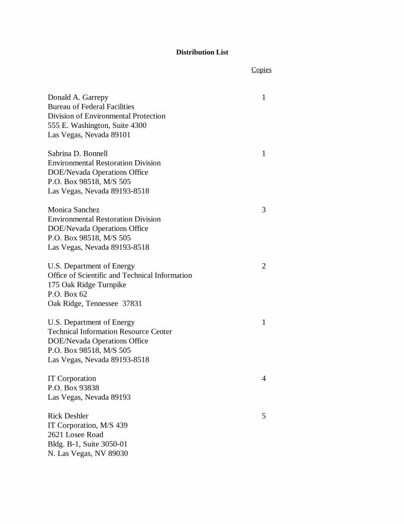
Distribution List
Copies
Donald A. Garrepy 1Bureau of Federal FacilitiesDivision of Environmental Protection555 E. Washington, Suite 4300Las Vegas, Nevada 89101
Sabrina D. Bonnell 1Environmental Restoration DivisionDOE/Nevada Operations OfficeP.O. Box 98518, M/S 505Las Vegas, Nevada 89193-8518
Monica Sanchez 3Environmental Restoration DivisionDOE/Nevada Operations OfficeP.O. Box 98518, M/S 505Las Vegas, Nevada 89193-8518
U.S. Department of Energy 2Office of Scientific and Technical Information175 Oak Ridge TurnpikeP.O. Box 62Oak Ridge, Tennessee 37831
U.S. Department of Energy 1Technical Information Resource CenterDOE/Nevada Operations OfficeP.O. Box 98518, M/S 505Las Vegas, Nevada 89193-8518
IT Corporation 4P.O. Box 93838Las Vegas, Nevada 89193
Rick Deshler 5IT Corporation, M/S 4392621 Losee RoadBldg. B-1, Suite 3050-01N. Las Vegas, NV 89030

Tim White 1IT Corporation, M/S 4392621 Losee RoadBldg. B-1, Suite 3050-01N. Las Vegas, NV 89030
Jenny Chapman 1Desert Research Institute755 East Flamingo RoadLas Vegas, NV 89119
Dave Madsen 2Bechtel NevadaP. O. Box 98521, MS NTS306Las Vegas, NV 89193-8521
Central Files 1IT Corporation, M/S 4392621 Losee RoadBldg. B-1, Suite 3050-01N. Las Vegas, NV 89030
U.S. Department of Energy Public Reading Room 1P.O. Box 98521, M/S NLV040Las Vegas, NV 89193-8521