Data Quality Objective Process: Applications in UK...
28
Data Quality Objective Process: Applications in UK Waste Stream Characterisation and De-licensing 11 th September 2013 Dr. Denis Buckley
Transcript of Data Quality Objective Process: Applications in UK...

Data Quality Objective Process: Applications in UK Waste Stream Characterisation and De-licensing
11th September 2013
Dr. Denis Buckley
Overview
This presentation covers:
• Data Quality Objectives (DQO)
• Basis of DQO
• Stages of a DQO
• Details of applications of DQO at three Magnox Ltd.
Sites:
• Chapelcross (Scotland)
• Trawsfynydd (Wales)
• Oldbury (England)
2

3
DQO SYSTEMATIC PLANNING:
The DQO process was developed in the USA, by the Environmental
Protection Agency (USEPA), to determine appropriate courses of
action in decommissioning and environmental remediation that are
underpinned by demonstrably defensible sampling.
• Based on the scientific method
• Step by step process
• Promotes better communication between individuals involved in any
environmental program
• A team can develop acceptance criteria for the quality of the data
collected and for the quality of the decision
• The planning process is the first element, which gives an open
methodology to the decision process
• Enables decision-makers to show what has been undertaken.

DQO DESIGNED TO ANSWER:
• Why are data needed?
• What type of data is needed?
• Where should the data be collected?
• When should data be collected?
• How will the data be used to make decisions?
• How often are you willing to make decision errors based
on the data?
• How much data is needed?
4

5
DQO PLANNING CAN BE USED TO:
• Should facilitate better, faster, and cost effective
method for meeting regulatory requirements.
• Enable the collection of the right amount of data
• Enables the sampling to be representative of the
population of interest
• Minimize unnecessary data
• Reduces the possibility of third-party challenges
• Reduces unnecessary re-work
• Reduce unnecessary clean up

6
• Using the DQO process will help to ensure that when
data collection has been completed it will have
accomplished two goals:
– provided sufficient data to make the required decisions
within a reasonable uncertainty.
– collect only the minimum amount of necessary data.
• The DQO process achieves this by determining the
quality and quantity of data needed, ensuring you don’t
collect data you:
– can’t use
– don’t need
– don’t use

7
SEVEN STEPS OF THE DQO PROCESS
• Step 1: State the problem To clearly define the Problem that has initiated the
study so that the focus of the project will be clear
• Step 2 : Identify the goals of the study Develop decision statements that require environmental
data to address the objective of the problem statement.
• Step 3: Identify information inputs Identify the inputs that will be required to resolve the
decision statements identified in Step 2 and to determine which inputs require environmental measurements.
• Step 4: Define the Boundaries of the Study To define the spatial and temporal boundaries that the
data must represent to support the decision statement

8
• Step 5: Develop the Analytic Approach
This step combines Steps 1 - 4 to produce the following
major elements to form decision rules:–Parameter of
interest–Unit of decision making–Action level–
Alternative actions
• Step 6: Specify Performance or Acceptance Criteria
To specify the decision makers' tolerable limits on
decision errors, which are used for limiting uncertainty
in the data.
• Step 7: Develop the Plan for Obtaining Data
Identify the most resource effective data collection and
analysis design that satisfies the DQOs specified in the
preceding 6 steps.

9
MAGNOX EXPERIENCE
• Magnox Ltd. have included the use of DQO in their
company standard for the characterisation of waste.
• The process has been used at three sites and through
the central programme resource on a variety of
characterisation programmes:
• Oldbury
Delicensing of 35 Hectares of previously nuclear licensed
site
• Trawsfynydd
Fuel cooling ponds decommissioning:
Inner pond walls - highly contaminated (coring for depth
analysis)
Ponds outer walls – zoned contamination
Basements & walkways – flooding and tread-wear.
Contaminated land under the Pond Complex

• Trawsfynydd Miscellaneous Activated Component (MAC)
Vaults
Fuel End Debris (FED) Vaults contaminated particulate
material
• Chapelcross:
Graphite Handling Facility (GHF) decommissioning and
demolition
Chapelcross Production Plant decommissioning analysis
Fuel cooling ponds decommissioning.
• Programmisation:
Sludges
Resins
Fuel End Debris Vault materials
Miscellaneous Contaminated Articles
10

SUCCESSFUL CHARACTERISATION OF GRAPHITE HANDLING FACILITY AT CHAPELCROSS
• The Chapelcross Power Station graphite handling
facility dates back to the 1940’s. The building has had
many different uses over its lifetime and was converted
into two separate buildings; the apprentice training
building and the graphite handling facility.
• The building is designated as a controlled area under
the Ionising Radiation Regulations 1999; with areas of
fixed contamination and the potential for loose
contamination to be present or created.
11

• The facility was taken out of use in the 1990’s and has
lain dormant in the intervening period.
• In 2006 the internal components of the building were
removed (including removing contaminated items from
the mortuary holes).
• This left the main structure of the building and a few
operational aspects such as the ventilation system
ducting in the roof space leading to the ventilation
system which is positioned adjacent to the building, and
the crane used for bringing in graphite flasks
12

13
1607, 2538
9709, 5373
5658, 8208
13761, 124
3632, 2958
11735, 5793
7684, 1069
15787, 3903
341, 6738
8443, 2014
4392, 4848
12495, 7683
2366, 439
10469, 3273
6418, 6108
14520, 1384
1353, 4218
COMPRESSOR
ROOM
GENERAL LABORATORY AREA
GRAPHITE STORE
PREP ROOM
EX CHANGE BAR
GAS STORE
WORKSHOP & STORAGE PITS
PLYWOOD WEATHERBOARD
6530
FIRST ISSUEISSUED FOR RECORD PURPOSES

• The area for characterisation was limited to:
• Floor Area
• Hunterston pit
• Mortuary Tubes
• Areas of known fixed floor contamination (hot spots)
• Ventilation duct
• Trench cover
• In summary the main components of the project scope
are the building fabric, the ventilation system(s) and the
concrete floor slab, particularly the section of floor slab
where the mortuary tubes, pits and troughs are situated.
It is anticipated that all of the components have
radiological contamination to varying degrees.
14

Traws Ponds Outer walls
15
• Trawsfynydd Power Station has a ponds complex on
site that has been used to decay cool fuel prior to
transport for reprocessing. As a consequence of the
nature of the materials and process the pond walls
became contaminated and this has generated a Low
Level Waste (LLW) waste stream.
• Sampling and characterisation of surfaces in buildings in
the ponds complex has been undertaken to determine
the depth of contamination to underpin the scabbling
depth to ensure that waste for sentencing is minimised.
• It is intended to take samples from the upper and lower
walkways and the outer walls of the pond lanes, and the
flask wash-down basement area of the complex for
radiochemical analysis.

16

This work was undertaken to underpin the current data,
and to give a more complete data set that will ensure
adequate confidence in the characterisation.
Samples from the following locations will be obtained:
• Upper Walkways paint scrapings & 50mm cores (10
each).
• Lower Walkways paint scrapings & 50mm cores (12
each) .
• Pond outer walls sample locations (paint scrapings,
concrete dust and where applicable joint mastic (24)).
• Basement paint scrapings and cores (14)
Samples are to be taken from several points along both
walkways; a total of forty four (44) core samples, from
twenty two paired locations.
17
North CD CBE Nort
h
South CD
North AB South AB CBW
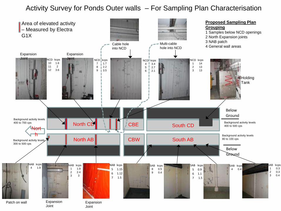
Area of elevated activity
– Measured by Electra
G1X
Cable hole
into NCD
Multi-cable
hole into NCD
Holding
Tank
Activity Survey for Ponds Outer walls – For Sampling Plan Characterisation
Expansion
Joint
Expansion
Joint
Expansion
Joint Patch on wall
Background activity levels
80 to 100 cps
Background activity levels
400 to 500 cps
Background activity levels
300 to 500 cps
Background activity levels
400 to 700 cps
NCD kcps
10 1.6
11 2
12 3.6
NCD kcps
7 1.7
8 2.2
9 3.5
NCD kcps
4 3.4
5 2.7
6 2.1
NCD kcps
1 14
2 13
3 13
NAB kcps
4 1.9 NAB kcps
1 1.9
2 2.4
3 3
NAB kcps
5 1.15
6 1.12
7 1.5
Proposed Sampling Plan
Grouping 1 Samples below NCD openings
2 North Expansion joints
3 NAB patch
4 General wall areas
SAB kcps
8 0.5
9 0.4
SAB kcps
5 0.9
6 1.1
7 1.5
SAB kcps
4 0.4
SAB kcps
1 0.3
2 0.3
3 0.4
Expansion
Joint

SUCCESSFUL DELICENSING – DQO AT OLDBURY
Objectives
• To vary the site license to remove approx. 35 hectares of land that are not required for operational purposes.
• To demonstrate that the NIA 65 ‘no danger’ criteria are met
• To demonstrate that there is no detrimental impact on future site operations.
19

SETTING AND HISTORY OF OLDBURY SITE
• Pre-construction: ‘green field site’
• Construction:
– Main site between 1961 to 1965
– Operational 1967
– Further developments – Drough Rhine redirected, OTC, Silt
Lagoons & Visitors Centre built and woodland, orchard &
meadows planted
• Operations:
– Security Fences
– Radiological Controls
– Active Effluent Discharges
20

OLDBURY DELICENSING LAND INVESTIGATION
• Desktop studies
• Large Areas Ground Survey
• Sampling Plans developed from DQO
• Soil and drainage samples, building surveys
• Hydrogeological assessment
• Sample analysis
• Data interpretation
21

REQUIREMENTS TO GENERATE A NUMBER OF SAMPLES.
• Develop a conceptual model of the site
• Contaminants of concern
• Study Boundaries: assessment of the need to zone /
sub-divide “study” into areas to be analysed
• Decision Rule
• A “null Hypothesis” for making a decision on assumption
on the condition of the site.
• An action level of activity that should not be breached.
• An estimate of the standard deviation of the activity.
• Decision Error Tolerances (area of uncertainty).
22

23
Sampling Areas:
1 – SL2a
2 – SL2b
3 – SL2 bund
4 – Other land
5 – OTC land
6 – Parking & Drains
7 – Buildings
8 – SL2 construction
waste

RADIOLOGICAL CRITERION FOR DELICENSING
• Magnox had to provide evidence to the ONR that there
is ‘no danger’ from ionizing radiations from anything on
that part of the site under consideration for de-licensing.
• The ONR requirement of ‘no danger’ is “any residual
radioactivity, above background, that will lead to a risk
of death to an individual using the site for any purpose,
of no greater than one in a million per year”
• The ONR criterion for de-licensing refers to the Euratom
Basic Safety Standards Directive (Euratom 96/29) which
sets a value of 10 microSieverts or less per year
• Comparing the measured radioactivity content of
samples collected with the IAEA radionuclide-specific
concentrations, it is possible to estimate the annual
dose arising from exposure to man-made radioactivity.
24

25
DE-LICENSING ACTION LEVEL
0.1 Bq g-1 is the most restrictive of the IAEA activity limits
for radionuclides of artificial origin was chosen. It is the
limit for several radionuclides of interest in this study
including Cs-137, which is likely to be the predominant
radionuclide of interest. The limit for each radionuclide is
apportioned using the quotient rule.
0.025 Bq g-1 was chosen as the standard deviation and is
an upper estimate based on a pessimistic assumption that
Cs-137 activity could range up to the action level of 0.1 Bq
g-1. IAEA Safety Standards Series, Application of the Concepts of Exclusion, Exemption and Clearance, RS-G-
1.7, 2004.

SAMPLE COLLECTION
• Shallow soil samples
• Following removal of surface vegetation, shallow soil samples were collected from the top 0.1m of using a rotary core cutter or, in ground conditions where the cutter could not collect a consolidated core, by removing a cube of soil using a small spade.
• Samples were placed in plastic tubs, labeled with the location, depth, and date of sample collection.
• A sub-sample was collected from samples that were scheduled to undergo analysis for tritium; these samples were placed in amber glass bottles and stored in cool boxes packed with ice.
26

COLLECTION OF DEEP SOIL SAMPLES
• A tracked percussive drilling rig was used to drill 6m deep boreholes at four locations within Silt Lagoon 2 and at one location on the eastern side of the lagoon bund. A further two 3m deep boreholes were drilled in the grassland and outside the Oldbury Technical Centre.
• Soil cores were collected in 0.5m long U4 liners, and these were subsequently sectioned to provide samples for analysis. Four samples were collected at the surface and at 2m intervals of depth for 6m boreholes, and from the surface and 1m depth intervals for 3m boreholes.
27
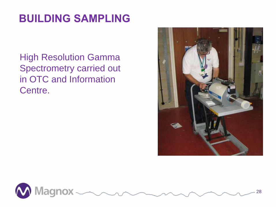
BUILDING SAMPLING
28
High Resolution Gamma
Spectrometry carried out
in OTC and Information
Centre.