Data Encoding Techniques - Computer Science |...
31
Physical Layer – Part 2 Data Encoding Techniques Networks: Data Encoding 1
Transcript of Data Encoding Techniques - Computer Science |...
Physical Layer – Part 2
Data Encoding Techniques
Networks: Data Encoding 1
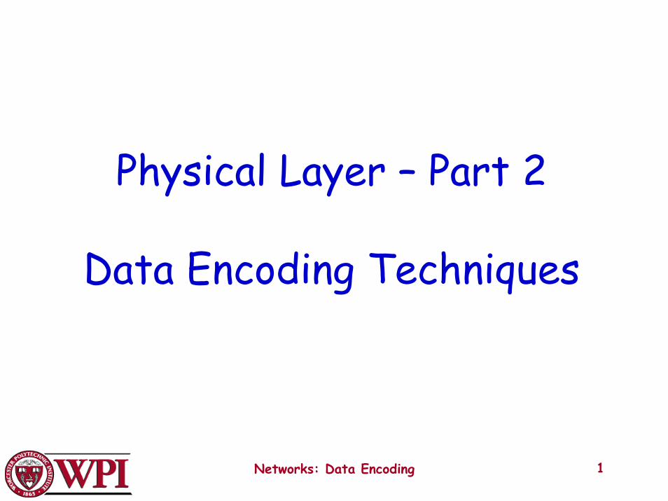
Analog and Digital Transmissions
Figure 2-23.The use of both analog and digital transmissions for a computer to computer call. Conversion is done by the modems and codecs.
Networks: Data Encoding 2
Data Encoding Techniques
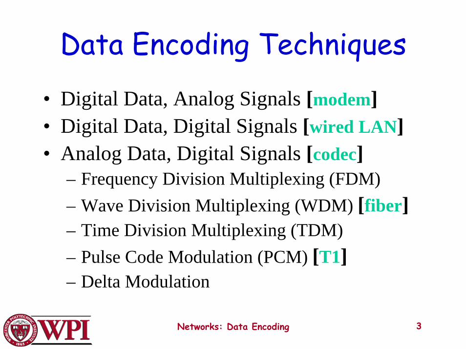
• Digital Data, Analog Signals [modem]• Digital Data, Digital Signals [wired LAN]• Analog Data, Digital Signals [codec]
– Frequency Division Multiplexing (FDM)– Wave Division Multiplexing (WDM) [fiber]– Time Division Multiplexing (TDM)– Pulse Code Modulation (PCM) [T1]– Delta Modulation
Networks: Data Encoding 3
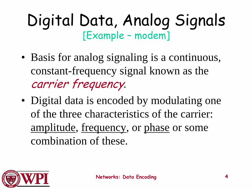
Digital Data, Analog Signals[Example – modem]
• Basis for analog signaling is a continuous, constant-frequency signal known as thecarrier frequency.
• Digital data is encoded by modulating one of the three characteristics of the carrier: amplitude, frequency, or phase or some combination of these.
Networks: Data Encoding 4
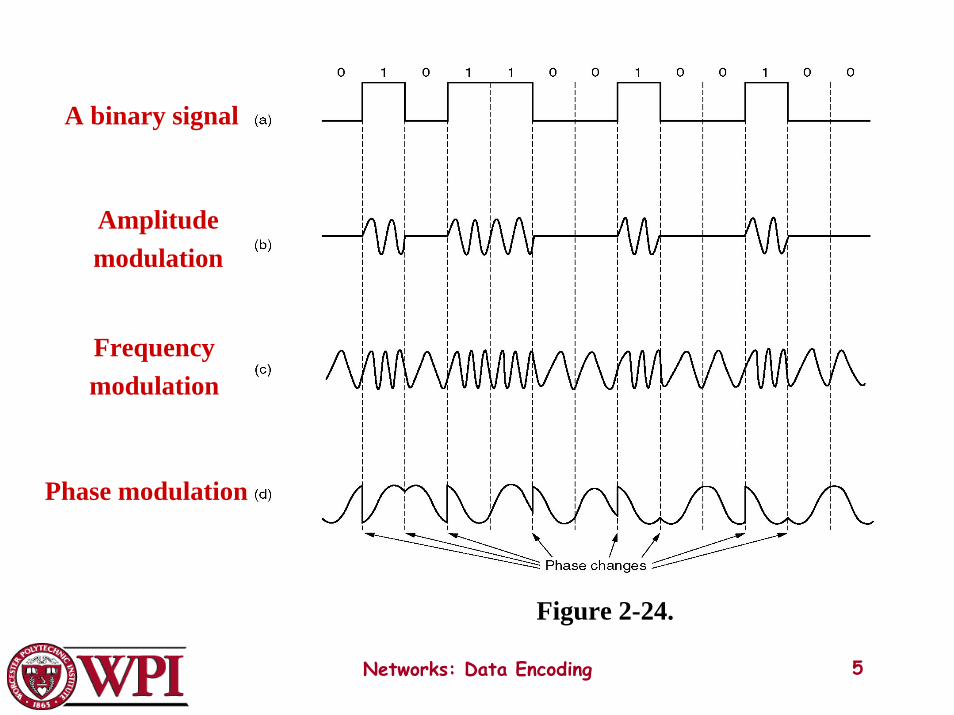
A binary signal
Frequencymodulation
Amplitudemodulation
Phase modulation
Networks: Data Encoding 5
Figure 2-24.
Modems
Networks: Data Encoding 6
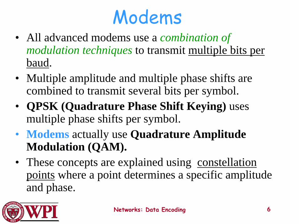
• All advanced modems use a combination of modulation techniques to transmit multiple bits per baud.
• Multiple amplitude and multiple phase shifts are combined to transmit several bits per symbol.
• QPSK (Quadrature Phase Shift Keying) uses multiple phase shifts per symbol.
• Modems actually use Quadrature Amplitude Modulation (QAM).
• These concepts are explained using constellation points where a point determines a specific amplitude and phase.
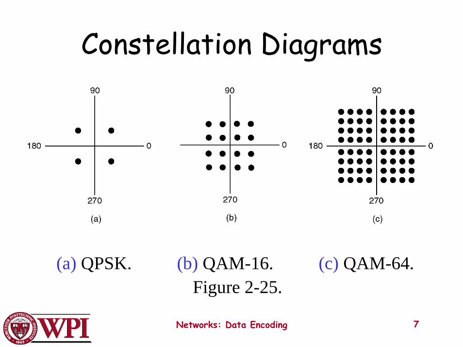
Constellation Diagrams
(a) QPSK. (b) QAM-16. (c) QAM-64.Figure 2-25.
Networks: Data Encoding 7
Digital Data, Digital Signals[the technique used in a number of LANs]
• Digital signal – is a sequence of discrete, discontinuous voltage pulses.
• Bit duration :: the time it takes for the transmitter to emit the bit.
• Issues– Bit timing– Recovery from signal– Noise immunity
Networks: Data Encoding 8
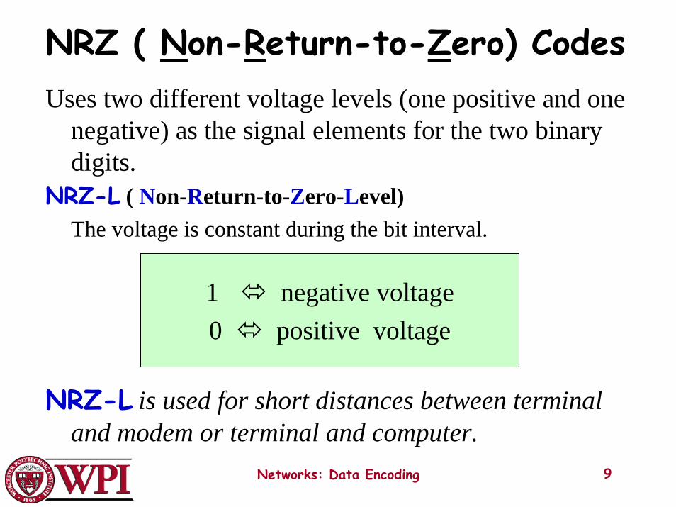
NRZ ( Non-Return-to-Zero) Codes
Networks: Data Encoding 9
Uses two different voltage levels (one positive and one negative) as the signal elements for the two binary digits.
NRZ-L ( Non-Return-to-Zero-Level)The voltage is constant during the bit interval.
NRZ-L is used for short distances between terminal and modem or terminal and computer.
1 negative voltage0 positive voltage
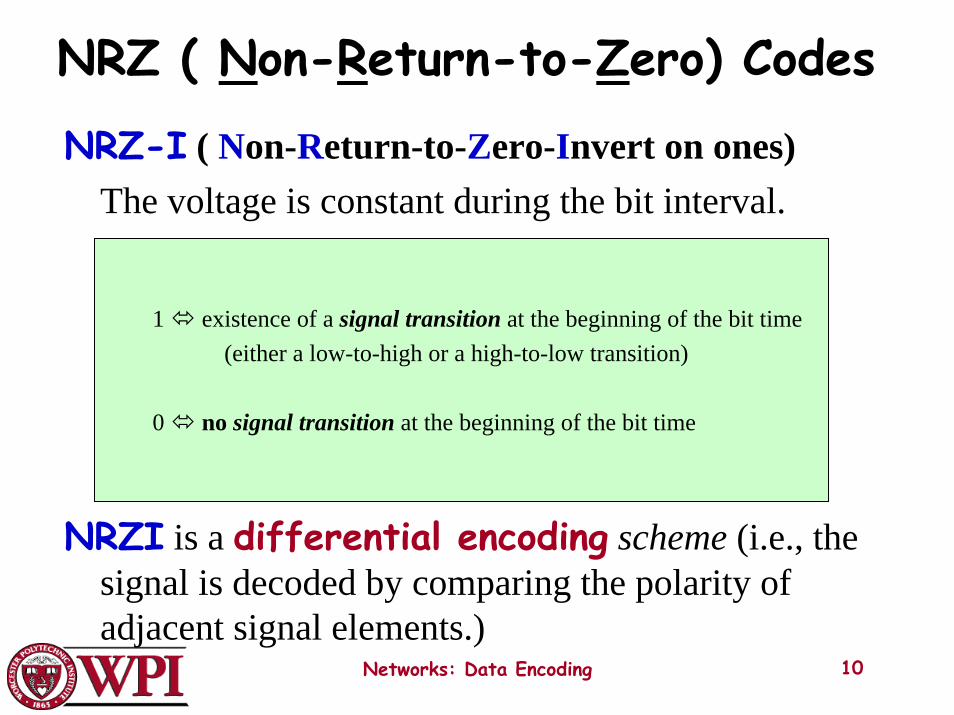
NRZ ( Non-Return-to-Zero) Codes
Networks: Data Encoding 10
NRZ-I ( Non-Return-to-Zero-Invert on ones)The voltage is constant during the bit interval.
NRZI is a differential encoding scheme (i.e., the signal is decoded by comparing the polarity of adjacent signal elements.)
1 existence of a signal transition at the beginning of the bit time(either a low-to-high or a high-to-low transition)
0 no signal transition at the beginning of the bit time
Bi –Phase Codes
Networks: Data Encoding 11
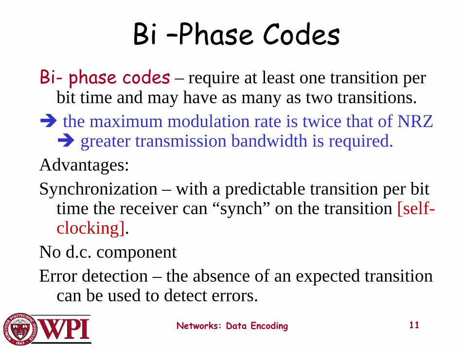
Bi- phase codes – require at least one transition per bit time and may have as many as two transitions.the maximum modulation rate is twice that of NRZ
greater transmission bandwidth is required.Advantages:Synchronization – with a predictable transition per bit
time the receiver can “synch” on the transition [self-clocking].
No d.c. componentError detection – the absence of an expected transition
can be used to detect errors.
Manchester Encoding
Networks: Data Encoding 12
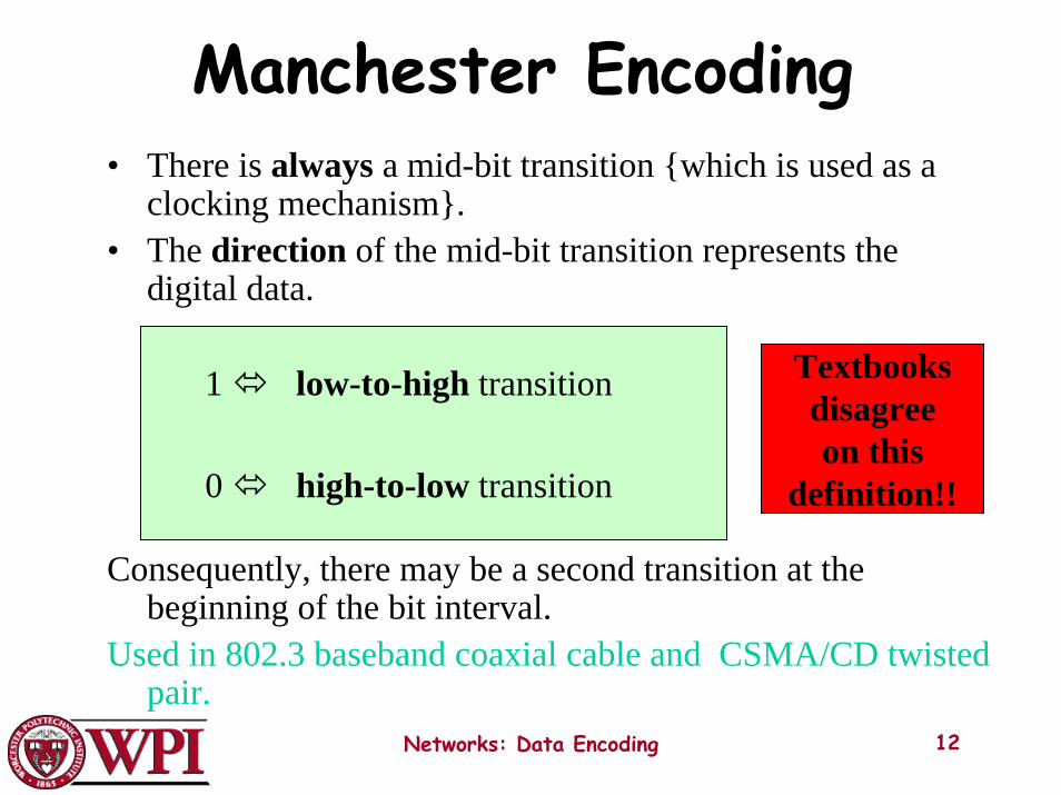
• There is always a mid-bit transition {which is used as a clocking mechanism}.
• The direction of the mid-bit transition represents the digital data.
Consequently, there may be a second transition at the beginning of the bit interval.
Used in 802.3 baseband coaxial cable and CSMA/CD twisted pair.
1 low-to-high transition
0 high-to-low transition
Textbooksdisagreeon this
definition!!
Differential Manchester Encoding
Networks: Data Encoding 13
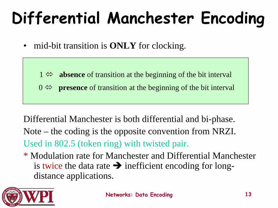
• mid-bit transition is ONLY for clocking.
Differential Manchester is both differential and bi-phase.Note – the coding is the opposite convention from NRZI.Used in 802.5 (token ring) with twisted pair.* Modulation rate for Manchester and Differential Manchester
is twice the data rate inefficient encoding for long-distance applications.
1 absence of transition at the beginning of the bit interval
0 presence of transition at the beginning of the bit interval

Bi-Polar Encoding
1 alternating +1/2 , -1/2 voltage0 0 voltage
• Has the same issues as NRZI for a long string of 0’s.
• A systemic problem with polar is the polarity can be backwards.
Networks: Data Encoding 14
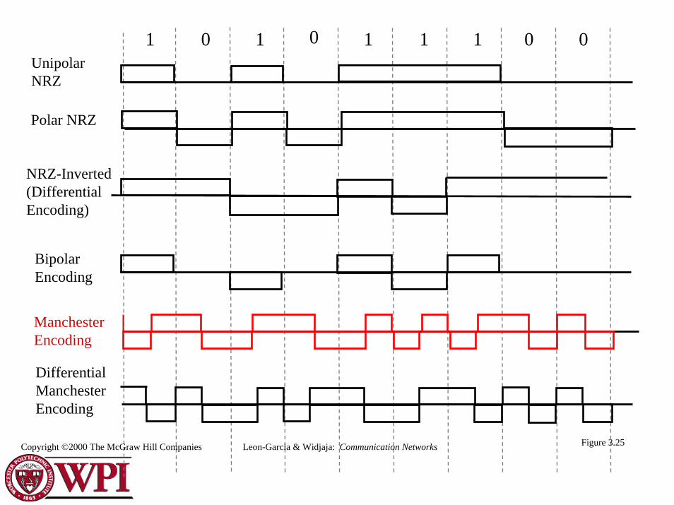
1 0 1 0 1 1 0 01UnipolarNRZ
NRZ-Inverted(DifferentialEncoding)
BipolarEncoding
DifferentialManchesterEncoding
Polar NRZ
Figure 3.25Copyright ©2000 The McGraw Hill Companies Leon-Garcia & Widjaja: Communication Networks
ManchesterEncoding
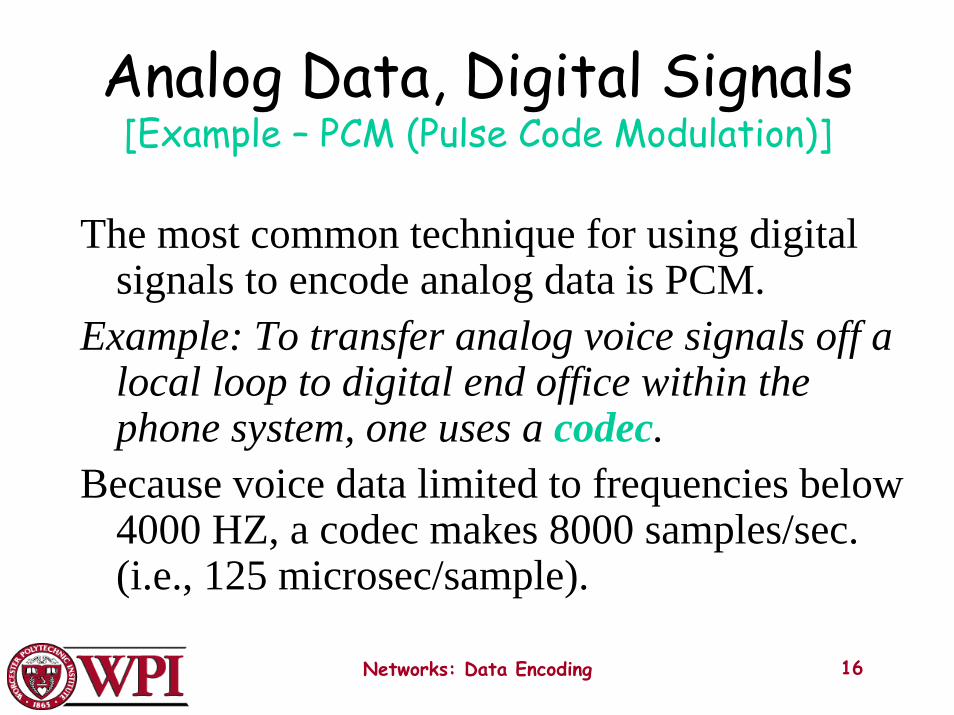
Analog Data, Digital Signals[Example – PCM (Pulse Code Modulation)]
The most common technique for using digital signals to encode analog data is PCM.
Example: To transfer analog voice signals off a local loop to digital end office within the phone system, one uses a codec.
Because voice data limited to frequencies below 4000 HZ, a codec makes 8000 samples/sec. (i.e., 125 microsec/sample).
Networks: Data Encoding 16
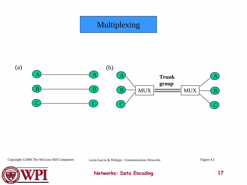
Multiplexing
(a)
Networks: Data Encoding 17
B B
C C
A A
B
C
A
B
C
A
MUXMUX
(b)Trunkgroup
Copyright ©2000 The McGraw Hill Companies Figure 4.1Leon-Garcia & Widjaja: Communication Networks
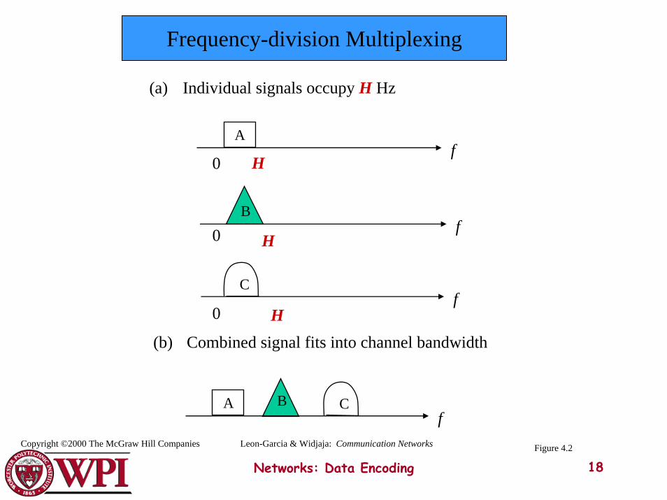
Frequency-division Multiplexing
(a) Individual signals occupy H Hz
Cf
Bf
Af
H
H
H
0
0
0
(b) Combined signal fits into channel bandwidth
A CBf
Networks: Data Encoding 18
Leon-Garcia & Widjaja: Communication NetworksCopyright ©2000 The McGraw Hill Companies Figure 4.2
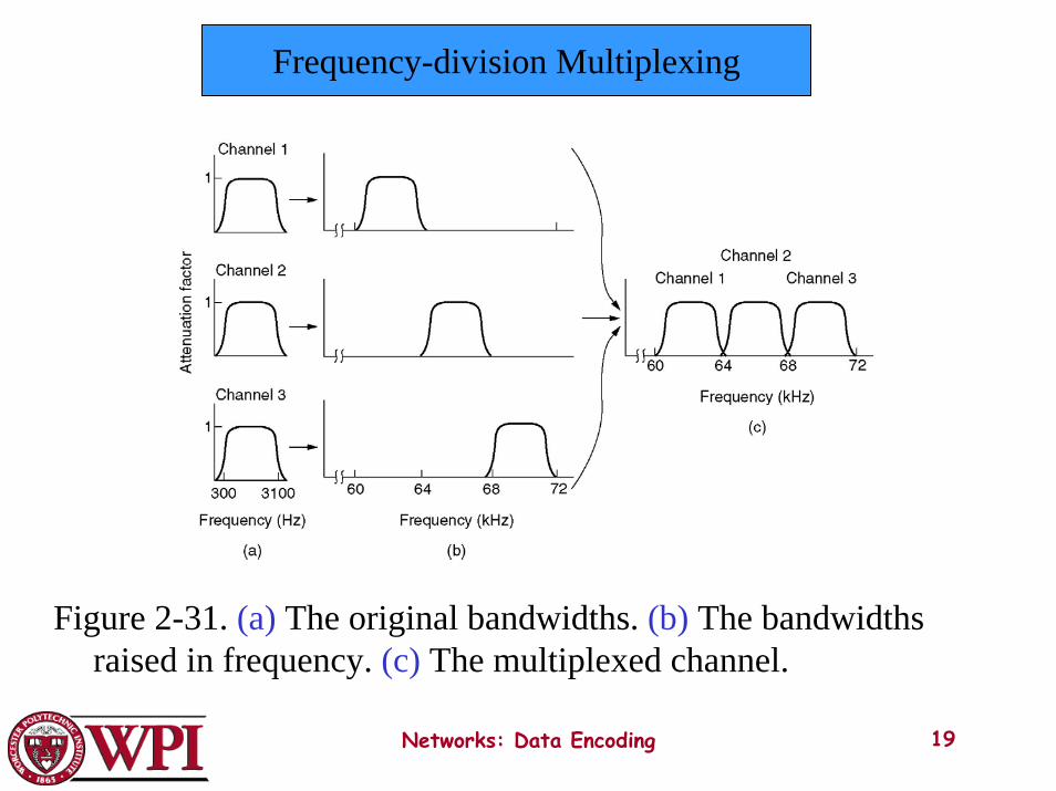
Frequency-division Multiplexing
Figure 2-31. (a) The original bandwidths. (b) The bandwidths raised in frequency. (c) The multiplexed channel.
Networks: Data Encoding 19
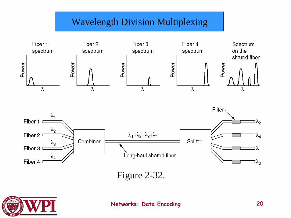
Wavelength Division Multiplexing
Wavelength division multiplexing.
Figure 2-32.
Networks: Data Encoding 20
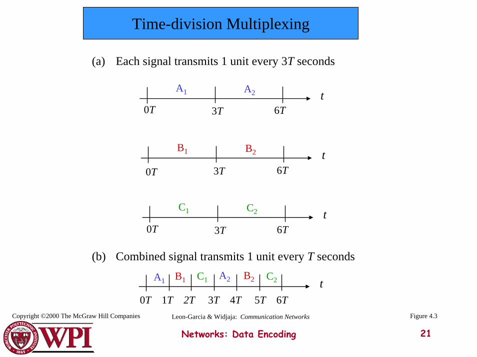
Time-division Multiplexing
(a) Each signal transmits 1 unit every 3T seconds
tA1 A2
tB1 B2
tC1 C2
3T0T 6T
3T0T 6T
3T0T 6T
(b) Combined signal transmits 1 unit every T seconds
tB1 C1 A2 C2B2A1
0T 1T 2T 3T 4T 5T 6T
Networks: Data Encoding 21
Copyright ©2000 The McGraw Hill Companies Figure 4.3Leon-Garcia & Widjaja: Communication Networks
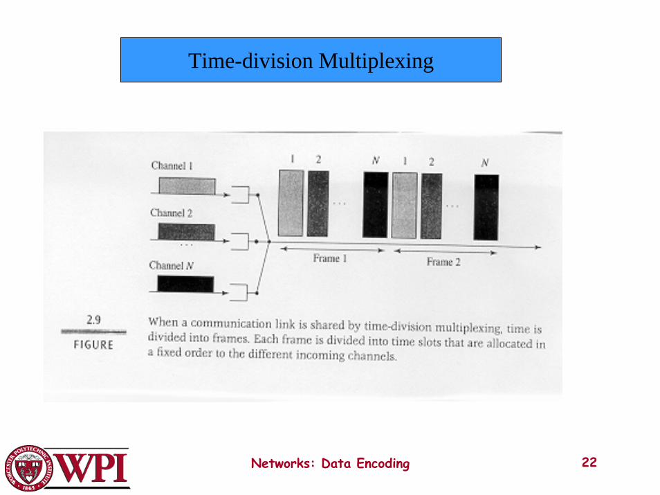
Time-division Multiplexing
Networks: Data Encoding 22
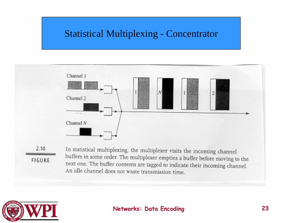
Statistical Multiplexing - Concentrator
Networks: Data Encoding 23
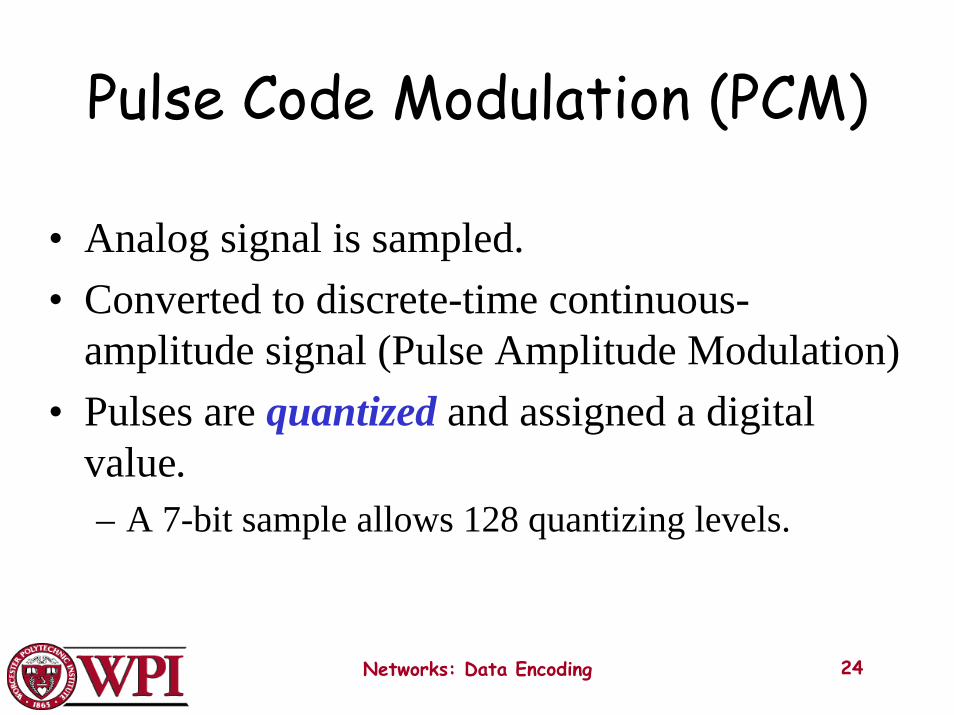
Pulse Code Modulation (PCM)
• Analog signal is sampled.• Converted to discrete-time continuous-
amplitude signal (Pulse Amplitude Modulation)• Pulses are quantized and assigned a digital
value.– A 7-bit sample allows 128 quantizing levels.
Networks: Data Encoding 24
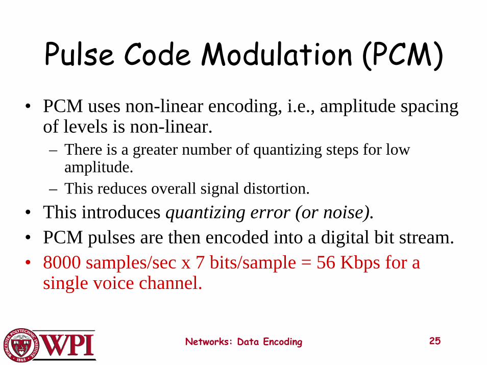
Pulse Code Modulation (PCM)• PCM uses non-linear encoding, i.e., amplitude spacing
of levels is non-linear.– There is a greater number of quantizing steps for low
amplitude.– This reduces overall signal distortion.
• This introduces quantizing error (or noise).• PCM pulses are then encoded into a digital bit stream.• 8000 samples/sec x 7 bits/sample = 56 Kbps for a
single voice channel.
Networks: Data Encoding 25
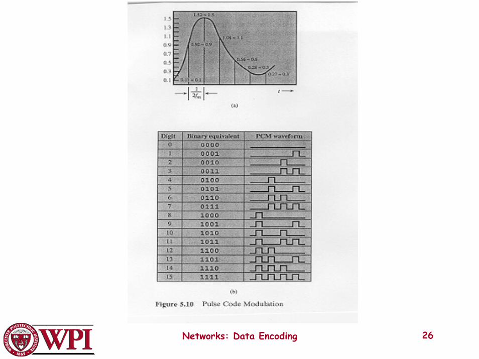
Networks: Data Encoding 26

PCMNonlinear Quantization Levels
Networks: Data Encoding 27
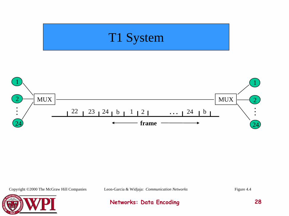
T1 System
2
24
1
MUXMUX
1
2
24
24 b1 2 . . .b2322
frame
24 . . .
. . .
Networks: Data Encoding 28
Leon-Garcia & Widjaja: Communication NetworksCopyright ©2000 The McGraw Hill Companies Figure 4.4
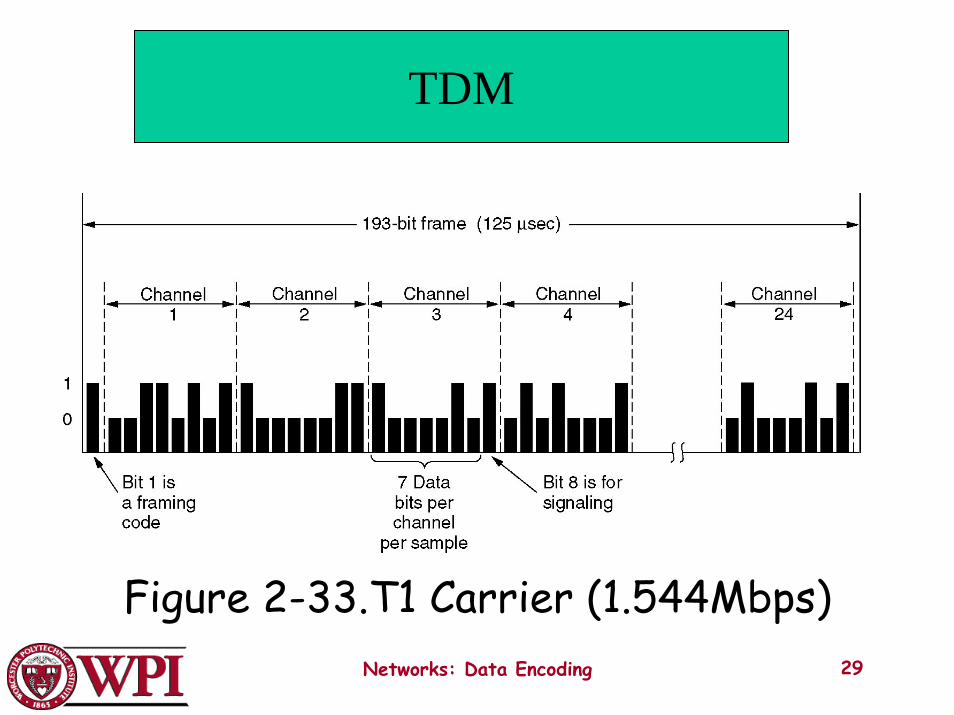
TDM
The T1 carrier (1.544 Mbps).
Networks: Data Encoding 29
Figure 2-33.T1 Carrier (1.544Mbps)
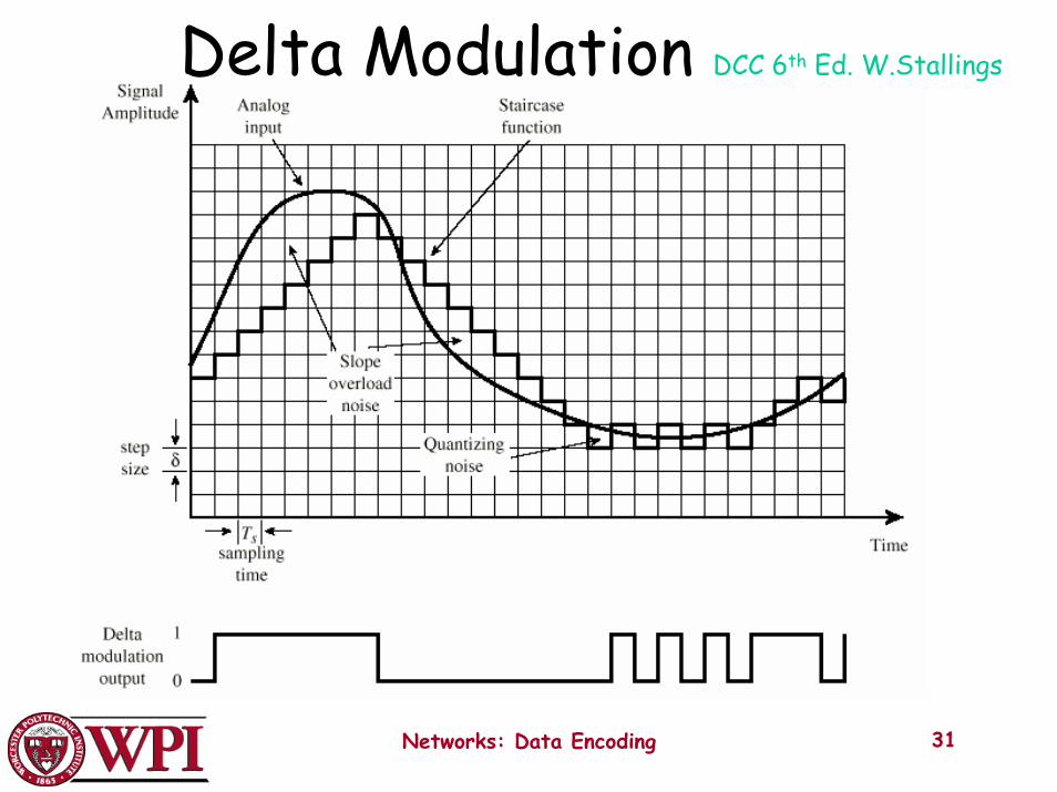
Delta Modulation (DM)
• The basic idea in delta modulation is to approximate the derivative of analog signal rather than its amplitude.
• The analog data is approximated by a staircase function that moves up or down by one quantization level at each sampling time. output of DM is a single bit.
• PCM preferred because of better SNR characteristics.
Networks: Data Encoding 30
Networks: Data Encoding 31
Delta Modulation DCC 6th Ed. W.Stallings


![Physical Layer – Part 2 Data Encoding Techniquesweb.cs.wpi.edu/~rek/Undergrad_Nets/C04/Data_Encoding.pdfNetworks: Data Encoding 4 Digital Data, Analog Signals [Example – modem]](https://static.fdocuments.net/doc/165x107/5b2356ff7f8b9a3a1b8b5f7c/physical-layer-part-2-data-encoding-rekundergradnetsc04dataencodingpdfnetworks.jpg)