Data Center Fabric with Nanosecond Accuracy - Use IEEE1588 ... · highlights the IEEE1588 PTP...
13
© 2012 Cisco and/or its affiliates. All rights reserved. This document is Cisco Public Information. Page 1 of 13 White Paper Data Center Fabric with Nanosecond Accuracy - Use IEEE1588 PTP on Nexus 3000 Switches June, 2012
Transcript of Data Center Fabric with Nanosecond Accuracy - Use IEEE1588 ... · highlights the IEEE1588 PTP...

© 2012 Cisco and/or its affiliates. All rights reserved. This document is Cisco Public Information. Page 1 of 13
White Paper
Data Center Fabric with Nanosecond Accuracy - Use
IEEE1588 PTP on Nexus 3000 Switches
June, 2012

© 2012 Cisco and/or its affiliates. All rights reserved. This document is Cisco Public Information. Page 2 of 13
Contents
What You Will Learn ................................................................................................................................................ 3
The Challenge of Today’s Timing Requirements .................................................................................................. 3 The Requirement: A Raising Bar .......................................................................................................................... 3 The Challenges ..................................................................................................................................................... 3 The Solution .......................................................................................................................................................... 4
IEEE 1588v2 Precision Time Protocol Overview ................................................................................................... 4 PTP Clocks ........................................................................................................................................................... 4 Best Master Clock Algorithm ................................................................................................................................. 5 PTP Master-Slave Clock Hierarchical Topology ................................................................................................... 5 Clock Synchronization Process ............................................................................................................................. 6 PTP Messages ...................................................................................................................................................... 7
Introducing PTP-Enabled Cisco Nexus 3000 Series Data Center Switches ....................................................... 8 Cisco Nexus 3000 Series IEEE1588 PTP Features .............................................................................................. 8 Cisco Nexus 3000 Series IEEE1588 PTP Architecture ......................................................................................... 9
IEEE1588v2 PTP Accuracy on Cisco Nexus 3000 Switches ................................................................................ 9 Packet Delay Variation (PDV) Verification .......................................................................................................... 10 1PPS Slave Verification ...................................................................................................................................... 11
Components of PTP enabled Network ................................................................................................................. 12 Grandmaster with Precise Time Source ............................................................................................................. 12 PTP Client ........................................................................................................................................................... 12
Conclusion ............................................................................................................................................................. 12
For More Information ............................................................................................................................................. 13
About the Author ................................................................................................................................................... 13

© 2012 Cisco and/or its affiliates. All rights reserved. This document is Cisco Public Information. Page 3 of 13
What You Will Learn
This document describes how to enable a highly accurate timing solution that can provide sub-microsecond
accuracy to today’s data center network and financial trading applications by enabling IEEE1588v2 Precision Time
Protocol (PTP), a distributed nanosecond accuracy timing synchronization protocol for packet network. This
document explains the challenging that today’s network and application is facing and why the IEEE1588 PTP time
synchronization protocol is needed to provide sub-microsecond accuracy and how the protocol works. It also
highlights the IEEE1588 PTP features that Cisco Nexus® 3000 Series Switches support, and explains the PTP
operation in Nexus 3000 by giving a packet walk. Last, it describes what’s the IEEE 1588 PTP accuracy that Nexus
3000 can provide and explains in details how the measurement is done. This document will be especially useful to
readers who are new to the IEEE1588 PTP protocol. It can be used together with other design and deployment
document that will be published in near future.
The Challenge of Today’s Timing Requirements
Accurate and precise timing information is critical to today’s data center networks and financial trading applications.
Network and system administrators need the visibility to see exactly what is happening on the network and when
each event occurs. Application developers and administrators need to correlate various event logs with processes
and applications in a very large and complex computing environment. Compliance and digital forensics also require
that every data transaction be precisely time stamped. It’s a fundamental requirement for today’s data network to
have a reliable, accurate and deployable time synchronization protocol so accurate timing information can be
provided to all the relevant elements of the data communication network, including routers, switches, servers and
applications.
The Requirement: A Raising Bar
Today the data center network is built with switches that is faster than ever, the servers are built with faster CPUs,
NICs, memories, hard drivers, applications on the servers are optimized to run faster and faster, this results in a
significant improvement on overall end-to-end latency. For example, Modern exchanges with latest technology
claim their round-trip market order latency is less than 100 microseconds. One of the most important component in
the solution to make this happen is the latest ultra-low latency cut-through Ethernet switch. Market leader Cisco
Nexus 3000 ultra low latency cut-through switch can forward the packet in less than 1 microsecond even for 9216
bytes jumbo packets (http://www.cisco.com/en/US/prod/collateral/switches/ps9441/ps11541/white_paper_c11-
661939.html). Now the question is, can networking timing protocol keep up?
The Challenges
Traditionally, Network Time Protocol (NTP) has been used to provide millisecond-level timing in packet-based
networks. However, millisecond accuracy is no longer adequate based on the reason listed in previous section.
Cleary, to gain visibility into exactly what happens in each process and steps in the server and switch,
organizations need a timing synchronization protocol that can provide microsecond level details across the whole
network.

© 2012 Cisco and/or its affiliates. All rights reserved. This document is Cisco Public Information. Page 4 of 13
GPS (Global Position System) can provide +/-100ns accuracy, but it need a dedicated media to distribute the
signal to the end user, which means every device in the network need either a BNC or mini-BNC interface, or IRIG-
B or other serial interface to receive the GPS timing information from a separate network. This make it impossible
to deploy in a data center network where even the smallest server farm will have tens of hundreds servers, not to
mention the routers, switches and other network elements that doesn’t have a dedicated special timing protocol
interface. Practically, we need a packet based, precise, and easy to implement and manage solution.
There are other serial timing distribution protocols can provide reasonable accuracy within a small network in a
tightly controlled environment but again they’re facing the same limitation as GPS and also very expensive.
The Solution
IEEE 1588 Precision Timing Protocol (PTP) is a very promising timing solution for today’s data center and financial
application, It’s originally designed for distributed measurement and control network, later on has been successfully
deployed in many large telecommunication networks worldwide in last several years due to the benefit it provides
below:
● Spatially localized systems with options for larger systems
● Packet based timing distribution and synchronization
● Nanosecond to sub-microsecond accuracy
● Low administrative operation, easy to mange and maintain
● Provisions for the management of redundant and fault-tolerant systems
● Low cost, low resource use, works well for both high-end and low-end devices
Software based PTP client has been available from many companies. Recently, realizing the importance to support
PTP for data center and financial applications, many server NIC vendors are planning to support PTP on their
latest NIC if they haven’t done so. Networking equipment vendor like Cisco has already supported PTP in many
products, now it added the PTP to the purpose-built data center low latency Nexus switches.
IEEE 1588v2 Precision Time Protocol Overview
IEEE 1588 PTP is a high-precision time synchronization protocol for distributed communication systems. IEEE
standardizes it in 2002 known as IEEE 1588v1 and later on updated it in 2008 known as IEEE 1588v2. The
protocol enables heterogeneous systems that include clocks of various inherent precision levels, resolutions, and
stability to synchronize with a grandmaster clock. IEEE 1588v2 PTP supports system wide synchronization
accuracy in the sub-microsecond range with little use of network and local clock computing resources. The
following sections introduce the main components of IEEE 1588v2 technology and its terminology. A good
understanding of the IEEE 1588v2 protocol will help you design a robust PTP timing solution for your data
communication network.
PTP Clocks
IEEE 1588v2 PTP is a packet-based two-way message exchange protocol for synchronizing a local clock with a
primary reference clock (a grandmaster clock) in hierarchical master-slave architecture. The type of PTP clock
used depends on the function performed by the PTP node in the network:
● Ordinary clock: This clock type has a single PTP port in a domain and maintains the time scale used in the
domain. It can be a master clock or a slave clock. For example, if the grandmaster clock is an ordinary
clock, a PTP slave on the server will be an ordinary clock, too.
© 2012 Cisco and/or its affiliates. All rights reserved. This document is Cisco Public Information. Page 5 of 13
● Boundary clock: This clock type has multiple PTP ports in a domain and maintains the time scale used in
the domain. It can be a master clock on one PTP port and simultaneously a slave on another port on the
same PTP node. This feature is very useful when you need to make PTP work in different domains or
translate from a different medium (for example, a network that uses time-division multiplexing [TDM] and a
packet network).
● Transparent clock: This type of clock measures the time taken for a PTP event message to transit the
device and provides this information to clocks receiving this event message. Two transparent clocks are
introduced in IEEE1588v2: end-to-end transparent clocks and peer-to-peer transparent clocks.
● End-to-end transparent clock: This type of transparent clock supports the use of the end-to-end delay
measurement mechanism between slave clocks and the master clock. Because the end-to-end transparent
clock does not calculate link propagation, it will not terminate PTP messages, and it should work with a
delay request-response mechanism between master and slave clocks.
● Peer-to-peer transparent clock: This type of transparent clock, in addition to providing PTP event transit
time information, provides the propagation delay of the link connected to the port the receives the PTP
event message. The peer delay mechanism is used to compute the mean path delay and clock offset
between two peer-to-peer transparent clocks.
Best Master Clock Algorithm
Best Master Clock Algorithm (BMCA) is used to select the master clock on each link, and it ultimately selects the
grandmaster clock for the whole PTP domain. It runs locally on each port of the ordinary and boundary clocks to
compare the local data sets with the received data from Announce messages to select the best clock on the link.
BMCA also runs the state decision algorithm to determine the PTP port states.
BMCA compares the following attributes from Announce messages with the precedence described here:
● Priority1: A user-configurable variable from 0 to 255; lower values takes precedence
● ClockClass: Defines the traceability of the time or frequency from the grandmaster clock
● ClockAccuracy: Defines the accuracy of a clock; lower values take precedence
● OffsetScaledLogVariance: Defines the stability of a clock
● Priority2: A user configurable variable from 0 to 255; lower value take precedence
● ClockIdentity: An 8-byte number typically in IEEE-EUI64 format to uniquely identify a clock
By changing the user-configurable values, network administrators can influence the way that the grandmaster clock
is selected. BMCA provides the mechanism that allows all PTP clocks to dynamically select the best master clock
(grandmaster) in an administration-free, fault-tolerant way, especially when the grandmaster clocks changes.
PTP Master-Slave Clock Hierarchical Topology
In an IEEE1588v2 PTP network, the master-slave hierarchical clock topology needs to be established in a PTP
domain before clock synchronization occurs. This tree-like topology is similar to spanning tree, the grandmaster
clock is most accurate clock in this clock hierarchy system and is the root of the tree so every PTP slave clock
synchronizes to it. In the PTP network, every port of the ordinary and boundary clocks examines the contents of all
PTP Announce messages received on the port, and then each port runs an independent PTP state machine to
determine the port status. Using BMCA, Announce messages, and the data sets associated with the ordinary or
boundary clock, the PTP port can be determined to be in one of the following three states:

© 2012 Cisco and/or its affiliates. All rights reserved. This document is Cisco Public Information. Page 6 of 13
● Master: The port is the source of time on the path served by the port.
● Slave: The port synchronizes with the device on the path on the port that is in the master state.
● Passive: The port is not the master on the path, nor does it synchronize with a master.
Usually IEEE 1588v2 relies on underlying networking protocols to eliminate loops, but IEEE 1588v2 also has the
built-in mechanism to break a loop based on the BMCA state machine on each PTP node. The BMCA helps
ensure that a single master port is selected on each segment.
Figure 1 shows that when a network has multiple master clocks - for example, because a new master clock is
added to the system - eventually only one is selected as the grandmaster clock, and it becomes the root of the
master-slave topology. The port on boundary clock 1 connected to master clock 2 will transit to a passive state,
and no master-slave relationship will be established between those two clocks. The dashed line in the figure
indicates that the master-slave relationship between two boundary clocks is not formed, and that one of the ports is
in a passive state as determined by the port state machine.
Figure 1. Clock Hierarchy
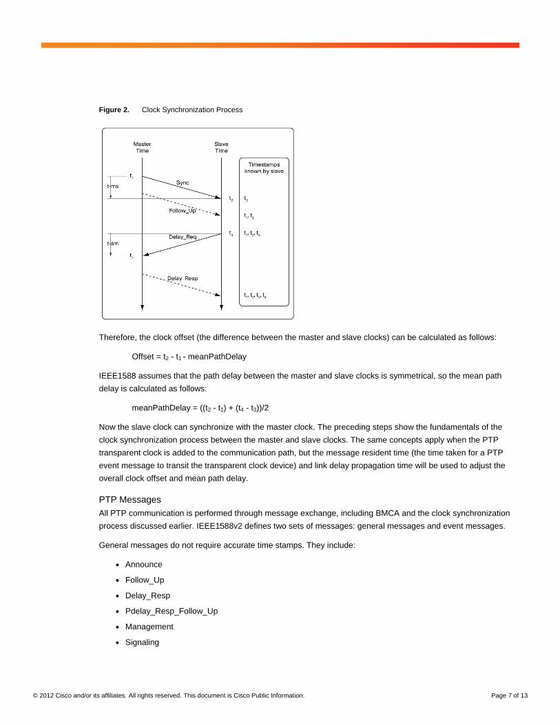
Clock Synchronization Process
Now that the master-slave clock hierarchy is established, the clock synchronization process starts. The
synchronization is achieved through a series of messages exchanged between master and slave clocks as shown
in Figure 2 and outlined here.
1. The master clock sends the Sync message. The time when the Sync message leaves the master is time-
stamped as t1, which can be embedded in the Sync message itself (one-step operation) or sent in the
Follow_Up message (two-step operation).
2. The slave receives the Sync message; t2 is the time that the slave receives the Sync message.
3. The slave sends the Delay_Req message, which is time-stamped as T3 when it leaves the slave and time-
stamped as T4 when the master receives it.
4. The master responds with a Delay_Resp message that contains time stamp t4.
© 2012 Cisco and/or its affiliates. All rights reserved. This document is Cisco Public Information. Page 7 of 13
Figure 2. Clock Synchronization Process
Therefore, the clock offset (the difference between the master and slave clocks) can be calculated as follows:
Offset = t2 - t1 - meanPathDelay
IEEE1588 assumes that the path delay between the master and slave clocks is symmetrical, so the mean path
delay is calculated as follows:
meanPathDelay = ((t2 - t1) + (t4 - t3))/2
Now the slave clock can synchronize with the master clock. The preceding steps show the fundamentals of the
clock synchronization process between the master and slave clocks. The same concepts apply when the PTP
transparent clock is added to the communication path, but the message resident time (the time taken for a PTP
event message to transit the transparent clock device) and link delay propagation time will be used to adjust the
overall clock offset and mean path delay.
PTP Messages
All PTP communication is performed through message exchange, including BMCA and the clock synchronization
process discussed earlier. IEEE1588v2 defines two sets of messages: general messages and event messages.
General messages do not require accurate time stamps. They include:
● Announce
● Follow_Up
● Delay_Resp
● Pdelay_Resp_Follow_Up
● Management
● Signaling
© 2012 Cisco and/or its affiliates. All rights reserved. This document is Cisco Public Information. Page 8 of 13
Events messages need to be accurately time stamped. They include:
● Sync
● Delay_Req
● Pdelay_Req
● Pdelay_Resp
As previously discussed, Sync, Delay_Req, Follow_Up, and Delay_Resp messages are used in the master-slave
clock synchronization process. The Pdelay_Req, Pdelay_Resp, and Pdelay_Resp_Follow_Up messages are used
to calculate the link delay between two transparent clocks. The Management messages are used to query and
update the PTP data sets maintained by the clocks. The Signaling messages are used for communication between
clocks for all other purposes.
The PTP event messages use User Datagram Protocol (UDP) destination port number 319; general messages use
UDP destination port 320.
Introducing PTP-Enabled Cisco Nexus 3000 Series Data Center Switches
Cisco Nexus 3000 Series IEEE1588 PTP Features
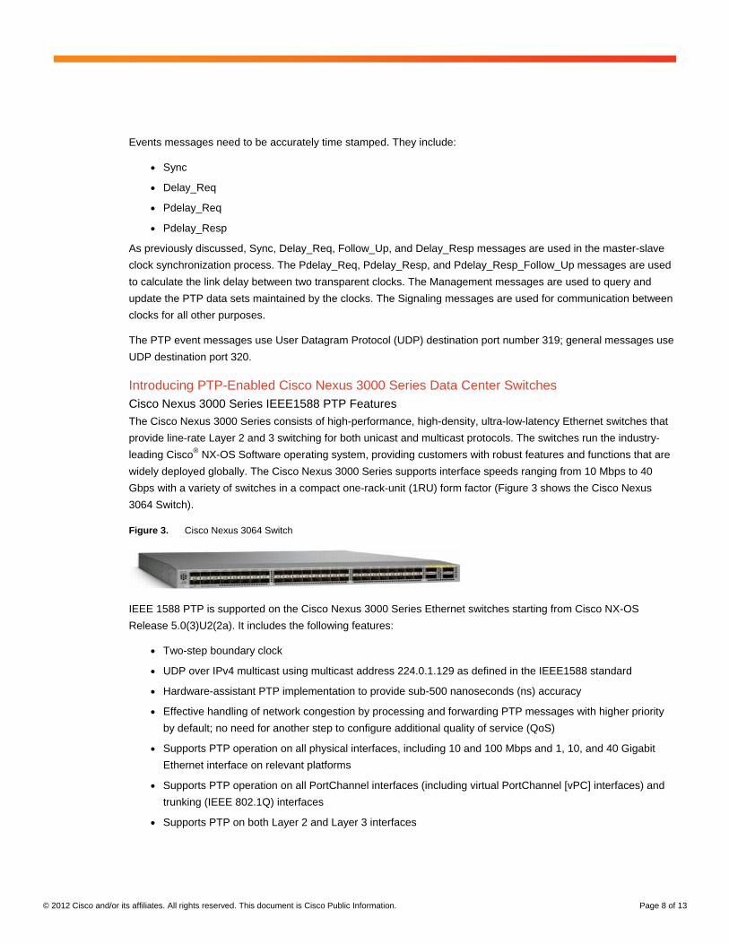
The Cisco Nexus 3000 Series consists of high-performance, high-density, ultra-low-latency Ethernet switches that
provide line-rate Layer 2 and 3 switching for both unicast and multicast protocols. The switches run the industry-
leading Cisco® NX-OS Software operating system, providing customers with robust features and functions that are
widely deployed globally. The Cisco Nexus 3000 Series supports interface speeds ranging from 10 Mbps to 40
Gbps with a variety of switches in a compact one-rack-unit (1RU) form factor (Figure 3 shows the Cisco Nexus
3064 Switch).
Figure 3. Cisco Nexus 3064 Switch
IEEE 1588 PTP is supported on the Cisco Nexus 3000 Series Ethernet switches starting from Cisco NX-OS
Release 5.0(3)U2(2a). It includes the following features:
● Two-step boundary clock
● UDP over IPv4 multicast using multicast address 224.0.1.129 as defined in the IEEE1588 standard
● Hardware-assistant PTP implementation to provide sub-500 nanoseconds (ns) accuracy
● Effective handling of network congestion by processing and forwarding PTP messages with higher priority
by default; no need for another step to configure additional quality of service (QoS)
● Supports PTP operation on all physical interfaces, including 10 and 100 Mbps and 1, 10, and 40 Gigabit
Ethernet interface on relevant platforms
● Supports PTP operation on all PortChannel interfaces (including virtual PortChannel [vPC] interfaces) and
trunking (IEEE 802.1Q) interfaces
● Supports PTP on both Layer 2 and Layer 3 interfaces

© 2012 Cisco and/or its affiliates. All rights reserved. This document is Cisco Public Information. Page 9 of 13
Cisco Nexus 3000 Series IEEE1588 PTP Architecture
The Cisco Nexus 3000 Series supports PTP operation with hardware assistance. The forwarding application-
specific integrated circuit (ASIC) can time-stamp the PTP packet in both the ingress and egress directions in
hardware. Figure 4 shows, at a high level, the PTP operations in Cisco Nexus 3064 switch. The same procedure
and process are used in all Cisco Nexus 3000 switches and provide the same feature and performance across the
whole Nexus 3000 series platforms.
Figure 4. PTP Operations in the Cisco Nexus 3000 Series
A PTP message is processed as follows (numbers correspond to the numbers in Figure 4):
1. The IEEE1588 packet is time-stamped at the ASIC ingress to record the event message arrival time.in
hardware.
2. The time stamp points to the first bit of the packet (following the start frame delimiter [SFD]).
3. The packet is copied to the CPU with the time stamp and destination port number.
4. The packet traverses the PTP stack. The advanced PTP clock argothrim in Nexus 3000 keeps track of all
the timing and frequency information and make necessary adjustment.
5. The packet is sent out at the egress port and marked internally as high priority packet to reduce any
possible delays inside the switch. The corresponding time stamp for the transmitted packet is available
from the FIFO transmission time stamp.
IEEE1588v2 PTP Accuracy on Cisco Nexus 3000 Switches
An Important aspect of the PTP implementation on Ethernet switch is its accuracy. For the packet network, PDV
(Packet Delay Variation) is one of the key factors that can impact the accuracy of the PTP clock. With its advanced
hardware and software capabilities, such as hardware stamping, special high priority queue for PTP packets as we
mentioned in previous section, Cisco Nexus 3000 series switch is designed to effectively handle the PDV of the
network and can provide <500ns accuracy in a scalable deployment scenario. Extensive lab testing has been done
to verify the capability of Nexus 3000 to handle PDV and its PTP clock accuracy. Two methods have been used on
the same topology to cross-check and verify the results.

© 2012 Cisco and/or its affiliates. All rights reserved. This document is Cisco Public Information. Page 10 of 13
● Packet-delay variation (PDV) verification
● One-pulse-per-second (1PPS) from PTP slave verification
The verification topology includes a grandmaster with a 12-channel GPS receiver, a Cisco Nexus 3064 Switch, and
a few PTP hardware slave clocks with 1PPS output. Anue 3500 is used to measure the PDV from Nexus 3064,
Agilent Oscilloscope and counters are used to measure the 1PPS signal between grandmaster and hardware PTP
client.
Figure 5. Clock accuracy measurement
Below is one set of the test results that can highlight the accuracy of Nexus 3000’s PTP implementation using the
above two methods.
Packet Delay Variation (PDV) Verification
During this test, the difference of the time stamp in the PTP event message and the reference time from the
grandmaster clock was measured to verify the PDV level that Nexus 3064 generates. During the 4-hour PDV
verification test, majority of the PDV falls within 30-70ns range, which is extremely small and very stable. As shown
in next section: 1PPS slave verification, this very small and stable PDV helps the PTP client to generate very
accurate clock output.
Figure 6. 4-hour PDV Verification on Nexus 3064

© 2012 Cisco and/or its affiliates. All rights reserved. This document is Cisco Public Information. Page 11 of 13
1PPS Slave Verification
Using the exact same topology as used in the PDV verification section, this approach measures the 1PPS signal
output from PTP client after the PTP-enabled switch then we can measure the accuracy of PTP-enabled switch
indirectly. In addition, because eventually, the accurate timing information need to be provided to the PTP client
installed on end user devices, either a server, a control unit or a leaf switch, So from that perspective it’s also
important to verify the accuracy on the client. First, we measures the delay (offset) of the PTP client’s 1PPS signal
when the client is directly connected to the grandmaster clock. Figure 7 shows the results. The mean delay (offset)
is approximately 22.9 ns with a standard deviation (Std Dev) of approximately 14.2 ns in a 4-hour measurement
period.
Figure 7. 1PPS Slave Verification Results When Grandmaster Clock directly connects to PTP Client
Then the measurement is taken again after the addition of the Cisco Nexus 3064 switch configured as a PTP
boundary clock between the grandmaster and slave clocks. The maximum delay is approximately 272 ns, mean
delay is 241.75ns with a Std Dev of 15.313 ns (Figure 8). Therefore, the Cisco Nexus 3000 Series introduced an
offset of approximately 218 ns in PTP client’s clock synchronization process. Looking at big picture from end-to-
end point of view, in a PTP enabled network built with Nexus 3000 switch, PTP client’s local clock is only 218ns
away from grandmaster clock, Thus, PTP client can provide unprecedented very accurate timing information to
different network element, servers, etc.
Notes: the actual test results in different lab may vary due to the accuracy of the grandmaster, test tools and
environment conditions, please consult your local Cisco account representative for additional information.

© 2012 Cisco and/or its affiliates. All rights reserved. This document is Cisco Public Information. Page 12 of 13
Figure 8. 1PPS Slave Verification Results After Adding a Cisco Nexus 3064 Switch
Components of PTP enabled Network
Typically a PTP-enabled data network consists of 3 key components: grandmaster, PTP client and PTP-enabled
switch acting as boundary clock or transparent clock. Nexus 3000 is a PTP boundary clock that we have described
its function and performance in great details in previous section, following sections will give a brief overview of
other two key components: grandmaster and PTP client.
Grandmaster with Precise Time Source
Every IEEE1588 PTP network needs a grandmaster to provide high accuracy time source. Currently the most
economical way to obtain the precise time source for the grandmaster is via GPS. GPS can provide +/- 100ns
accuracy when it’s installed and operated properly. PTP grandmaster’s built-in GPS receive will convert the GPS
timing information to PTP time information, typically UTC. Then the UTC time will be delivered to all PTP clients in
the way we described earlier.
PTP Client
PTP client is required to be installed on servers, network monitoring and performance analysis devices or any other
devices that want to use the precise timing information provided by PTP, usually it’s an ordinary clock. There are
two kinds of clients: pure software PTP clients and hardware-assistant PTP clients. The PTP software clients
implement IEEE1588 PTP stack in software and is available from many vendors, there is also an open source
version for Linux distribution. The hardware-assistant PTP client typically is a PCI-E bus card with a dedicated on-
board chip to process the PTP packet; it also provides additional clocking output, such as 10Mhz, 1PPS, and IRIG-
B timing code.
Conclusion
IEEE1588 PTP provides a reliable, highly accurate distributed time synchronization solution for today’s networks,
which require nanosecond or sub-microsecond accuracy. PTP is easy to implement with very little administrative
effort and can tolerate network and clock failure with built-in fault-tolerant mechanisms. The Cisco Nexus 3000
Series offers the industry’s only PTP-enabled data center switches. Turning on the PTP function on a Cisco Nexus
3000 Series Switch will immediately improve your network’s time resolution, providing 1000 times better
performance than the existing NTP solution. PTP with the Cisco Nexus 3000 Series together can greatly improve
your visibility into network and application events.
© 2012 Cisco and/or its affiliates. All rights reserved. This document is Cisco Public Information. Page 13 of 13
For More Information
For more information about the IEEE1588-2008 Precision Time Protocol, see the IEEE Standard for a Precision
Clock Synchronization Protocol for Networked Measurement and Control Systems.
For more information about the Cisco Nexus 3000 Series, please see the detailed product information at the
product homage page at http://www.cisco.com/go/nexus3000.
About the Author
Yang Yang is a senior Technical Marketing Engineer currently focused on high-performance low-latency switch
architecture, performance and end-to-end data center solutions. IEEE 1588 PTP performance and solution is one
of his recent projects.
Printed in USA C11-690975-02 06/12