Data acquisition application for continuous emission ... · System manual TD/DAA-EN Rev. A DAA Data...
44
System manual TD/DAA-EN Rev. A DAA Data acquisition application for continuous emission monitoring – Software version 1.2.4 Performance-tested program system for acquisition and handling of continuous emission data Measurement made easy Change from one to two columns
Transcript of Data acquisition application for continuous emission ... · System manual TD/DAA-EN Rev. A DAA Data...

System manual TD/DAA-EN Rev. A
DAA Data acquisition application for continuous emission monitoring – Software version 1.2.4
Performance-tested program system for acquisition and handling of continuous emission data Measurement made easy
Change from one to two columns


DAA Data acquisition application for continuous emission monitoring – Software version 1.2.4 System manual TD/DAA-EN Revision A Edition June 2017
This manual is protected by copyright. The translation, duplication and distribution in any form, even in a re-vised edition or in extracts, in particular as a reprint, by photomechanical or electronic reproduction or in the form of storage in data processing systems or data networks are prohibited without the consent of the copy-right holder and will be prosecuted under civil and criminal law.
4 TD/DAA-EN Rev. A | DAA System manual
Table of Contents
1 Introduction ..................................................................................................................... 6
2 System overview ............................................................................................................. 7
2.1 Functions overview ................................................................................................ 7 2.2 System configuration ............................................................................................. 8 2.3 Replication / Redundancy system ....................................................................... 10 2.4 External systems ................................................................................................. 11
3 Function model ............................................................................................................. 12
3.1 Overview .............................................................................................................. 12 3.2 Program units ...................................................................................................... 12
3.2.1 MAIN ...................................................................................................... 12 3.2.2 IORD.n ................................................................................................... 12 3.2.3 IOWR.n .................................................................................................. 12 3.2.4 FLD ........................................................................................................ 13 3.2.5 MTA+ ..................................................................................................... 13 3.2.6 BACKUP ................................................................................................ 13 3.2.7 AR.FLD, AR.MTA, AR.HLP, AR.MON ..................................................... 13 3.2.8 LOGWR ................................................................................................. 13 3.2.9 NET.n ..................................................................................................... 13 3.2.10 IOTP.n .................................................................................................... 13 3.2.11 MBTS.n .................................................................................................. 13 3.2.12 S5RK.n................................................................................................... 13 3.2.13 TS01.n ................................................................................................... 13 3.2.14 DSMB.n.................................................................................................. 13 3.2.15 HBEAT ................................................................................................... 14 3.2.16 USER ..................................................................................................... 14
3.3 Directories ............................................................................................................ 14
4 TALAS/7-IO modules .................................................................................................... 15
4.1 General ................................................................................................................ 15 4.2 Power supply ....................................................................................................... 15 4.3 Analog inputs ....................................................................................................... 16 4.4 Digital inputs ........................................................................................................ 16 4.5 Digital outputs ...................................................................................................... 17 4.6 Analog outputs ..................................................................................................... 17 4.7 Modules ............................................................................................................... 17 4.8 Label .................................................................................................................... 18 4.9 Serial number ...................................................................................................... 18 4.10 Contacts and indicator lights ................................................................................ 18
5 Beckhoff Bus Terminals ................................................................................................. 19
6 System requirements .................................................................................................... 20
6.1 DAA ..................................................................................................................... 20 6.2 TALAS/7-IO .......................................................................................................... 20

DAA System manual | TD/DAA-EN Rev. A 5
7 Maintenance ................................................................................................................. 21
7.1 System messages ............................................................................................... 21 7.2 System status ...................................................................................................... 26 7.3 Replacement devices .......................................................................................... 27
8 Installation ..................................................................................................................... 28
8.1 Introduction .......................................................................................................... 28 8.2 Preparation .......................................................................................................... 28 8.3 Windows .............................................................................................................. 28 8.4 Firewall ................................................................................................................ 28 8.5 DAA ..................................................................................................................... 28 8.6 Parameterization .................................................................................................. 30
9 Related documents ....................................................................................................... 31
10 Annex A Dimensions of the TALAS/7-IO modules ........................................................ 32
10.1 TALAS/7-IO4 ........................................................................................................ 32 10.2 TALAS/7-IO8 ........................................................................................................ 32
11 Annex B Layout of the TALAS/7-IO modules ................................................................ 33
11.1 TALAS/7-IO8/AI ................................................................................................... 33 11.2 TALAS/7-IO8/DI ................................................................................................... 33 11.3 TALAS/7-IO8/AIDI ................................................................................................ 34 11.4 TALAS/7-IO8/AO ................................................................................................. 34 11.5 TALAS/7-IO4/AI, TALAS/7-IO4/DI ........................................................................ 35 11.6 TALAS/7-IO4/AIDI, TALAS/7-IO4/DIDO ............................................................... 35 11.7 TALAS/7-IO4/AO, TALAS/7-IO4/DO .................................................................... 36 11.8 TALAS/7-IO4/AODO ............................................................................................ 36
12 Annex C Private network .............................................................................................. 37
13 Annex D Setup of the firewall ........................................................................................ 38
Table of Figures Figure 1: DAA and its environment ........................................................................................... 7 Figure 2: Internal configuration 1 .............................................................................................. 8 Figure 3: Internal configuration 2 .............................................................................................. 8 Figure 4: NAS server, internal variant 1 (acc. to internal configuration 2) ................................ 9 Figure 5: NAS server, internal variant 2 (acc. to internal configuration 2) ................................ 9 Figure 6: NAS server, external variant ..................................................................................... 9 Figure 7: External configuration ............................................................................................. 10 Figure 8: Replication with external DAA ................................................................................. 10 Figure 9: Replication with internal DAA .................................................................................. 11 Figure 10: Program units of DAA ........................................................................................... 12 Figure 11: Digital input connection ......................................................................................... 16 Figure 12: Case label ............................................................................................................. 18 Figure 13: Advice for installation ............................................................................................ 29 Figure 14: Installation of DAA ................................................................................................. 29 Figure 15: Installed service for DAA ....................................................................................... 29

6 TD/DAA-EN Rev. A | DAA System manual
1 Introduction
DAA and CEM-DAS are a qualified programming system for acquisition and management of continuous emission data. They are designed for use as an intranet application and include DAA (Data Acquisition Application) as well as CEM-DAS (Continuous Emission Monitoring Data Acquisition System), a software component running on a PC. DAA consists of a software component (program) and one or several TALAS/7-IO input and output modules. The term DAA may refer either only to the software component, or to the complete system consisting of the software component and the input/output modules. In each case, the mean-ing of DAA should always be clear from the context. DAA runs on Microsoft Windows on a PC as a Windows service or as a program in the fore-ground. On one PC only one DAA can be executed.

DAA System manual | TD/DAA-EN Rev. A 7
2 System overview
2.1 Functions overview
Figure 1: DAA and its environment
The external interfaces of DAA are summarized in the context diagram depicted in Figure 1. DAA acquires the process data via several TALAS/7-IO modules that are connected to it via network. In addition, data are output to the process by DAA via the TALAS/7-IO modules. The time of DAA is synchronized with the time of CEM-DAS. Connection and data exchange to CEM-DAS is carried out via a network. Additionally, a data exchange with an external system (control system, …) is possible. As of version 1.2, DAA can also communicate with an AMS via the digital interface VDI 4201 and capture measured values. The functionality and parameterization of this interface are de-scribed in /3/.

8 TD/DAA-EN Rev. A | DAA System manual
2.2 System configuration The following illustrations show possible configurations of CEM-DAS and DAA. Users only need network access to CEM-DAS.
Figure 2: Internal configuration 1
In Figure 2, a DAA is executed on the same PC as CEM-DAS. Both applications communi-cate via the internal network interface. DAA is connected to the TALAS/7-IO modules via its private network (Annex C).
Figure 3: Internal configuration 2
In Figure 3, a DAA is executed on a PC separated from CEM-DAS. Both applications com-municate independent of the company network via a separate private network connection (variant 1)1. DAA is connected to the TALAS/7-IO modules via its private network (Annex C). This variant should be applied if the DAA PC is used for data archiving (ZIP, archive) of CEM-DAS. The TALAS/7-IO modules can then be accessed via “Remote Desktop” to the DAA PC from the CEM-DAS PC. Alternatively, CEM-DAS may also be added to the private network (Annex C) of DAA and the TALAS/7-IO modules (variant 2). This variant allows direct access to the TALAS/7-IO mod-ules from the CEM-DAS PC. Variant 2 must of course be applied if the DAA PC only has one network interface. If an NAS server shall be integrated into the internal network, both variant 1 and variant 2 can be applied. In the first case, CEM-DAS and the NAS server are located in the private network 192.168.1.0/24.
1 For variant 1, IP addresses from network 192.168.1.0/24 should be selected (Annex C).

DAA System manual | TD/DAA-EN Rev. A 9
Figure 4: NAS server, internal variant 1 (acc. to internal configuration 2)
In the second case, all systems are located in the private network 192.168.0.0/24.
Figure 5: NAS server, internal variant 2 (acc. to internal configuration 2)
Of course the NAS server may also be located in the company network.
Figure 6: NAS server, external variant
In Figure 7, several DAA, each executed on separate PCs, are connected via the company network to CEM-DAS, which is executed on a separate PC. Each DAA is connected to its TALAS/7-IO modules via its private network (Annex C).

10 TD/DAA-EN Rev. A | DAA System manual
Figure 7: External configuration
2.3 Replication / Redundancy system DAA can be used in an CEM-DAS replication / redundancy system. The following two config-urations are possible.
Figure 8: Replication with external DAA
One or more DAA is/are installed on separate PCs. The master as well as the backup of CEM-DAS request data from DAA. However, the time is only synchronized by the master.

DAA System manual | TD/DAA-EN Rev. A 11
Figure 9: Replication with internal DAA
Internal DAA systems are installed on the master as well as on the backup of CEM-DAS. Both DAA can receive the UDP telegrams of the TALAS/7-IO modules and evaluate them with the identical parameterization. The control points of the TALAS/7-IO modules are only set by the DAA master. The master also establishes a TCP connection to the DAA backup, which disables setting of the control points by the DAA backup. If there is no longer a connection between DAA master and back-up (e.g. due to a failure of the master), the DAA backup will resume setting of the control points. When loading new DAA parameters (only possible from the CEM-DAS master), the loader program will make sure that the same parameters are loaded to both DAA. Since the DAA master and the loader program require the IP address of the DAA backup, it is necessary to parameterize this IP address in the options of DAA as ‚talas7.backup.ip=n.n.n.n‘.
2.4 External systems DAA can exchange data with external systems: • data transmission via Modbus TCP/RTU (see /2/) • data transmission via S5-RK512 (Siemens) • data transmission via ABB TS01 interface

12 TD/DAA-EN Rev. A | DAA System manual
3 Function model
3.1 Overview The functions of DAA are realized by the following program units (threads) within the DAA program. Program units ending in ‚n‘ may be present several times, with ‚n‘ running from 0, 1, etc.
Figure 10: Program units of DAA
3.2 Program units
3.2.1 MAIN This program unit is the first to be called up upon starting of the program DAA. It initializes the internal memory units and reads in the previous or new parameters from a file. If a back-up is available, the program unit will read from it the last available status of DAA. After that, it starts all other program units and monitors their execution.
3.2.2 IORD.n This program unit waits for the input values sent by the TALAS/7-IO input modules via UDP telegrams. The received values are then compressed for the parameterized devices.
3.2.3 IOWR.n This program unit sends the output values to the TALAS/7-IO output modules and checks whether they were correctly set.

DAA System manual | TD/DAA-EN Rev. A 13
3.2.4 FLD The program unit FLD runs in the measured values sequence, retrieves the acquired input values and compiles the measured values after parameterization. Also, it increases the coun-ter for short term values and last slow average (LSA). In addition, it calculates the binary links (B-MS) and then calculates and provides the output values.
3.2.5 MTA+ The program unit MTA+ runs in the short term values sequence and creates short term val-ues, running slow average (RSA) and, as required, the last slow averages, if their integration time has expired.
3.2.6 BACKUP This program unit cyclically saves the current state of DAA, so that the previously collected data may be reconstructed after a restart of DAA.
3.2.7 AR.FLD, AR.MTA, AR.HLP, AR.MON These program units cyclically safe the created values and system messages in archive files. AR.FLD saves the measured values and AR.MTA saves the short term values and last slow averages. AR.MON ensures that the parameterized memory space for the data is adhered to. AR.HLP executes longer lasting actions on the storage media on behalf of AR.MON.
3.2.8 LOGWR This program unit writes the log messages put out by DAA into files. By default, no log files are written, only an error file is created.
3.2.9 NET.n These program units communicate via TCP with the corresponding process “dasDaa” of CEM-DAS. They transmit the requested values and receive a new parameter file from CEM-DAS.
3.2.10 IOTP.n This program unit communicates via TCP with a TALAS/7-IO module, from which it receives the input values. The received values are then compressed for the parameterized device. Al-so, it sends the output values to the module and checks whether these have been set cor-rectly.
3.2.11 MBTS.n This program unit works as a MODBUS TCP server. Input data can be written and output da-ta can be read via this program unit. Functionality and parameterization of this interface are described in /2/.
3.2.12 S5RK.n This program unit realizes the S5-RK512 interface.
3.2.13 TS01.n This program unit realizes the ABB-TS01 interface.
3.2.14 DSMB.n This program unit realizes the digital interface according to VDI 4201 via Modbus. Function-ality and parameterization of this interface are described in /3/.

14 TD/DAA-EN Rev. A | DAA System manual
3.2.15 HBEAT This program unit (not depicted) runs to a DAA master, if there is a replication (see Section 2.3). It cyclically transmits its life signal to the DAA backup.
3.2.16 USER This program unit (not depicted) builds the DAA user interface.
3.3 Directories The installation directory of DAA can be freely selected during installation. The following di-rectories are created below this installation directory: Directory Meaning SYS Contains the cyclically created backup files and the error file XLG Contains the optionally created log files FLD Contains the archived measured values MTA Contains the archived short term values STA Contains the archived last slow averages

DAA System manual | TD/DAA-EN Rev. A 15
4 TALAS/7-IO modules
4.1 General TALAS/7-IO is the name under which NIS provides measurement and control modules mountable on EN 50022 DIN rails. Mounted in 4 or 8 WU (width unit @17.5mm per width unit) cases, they can provide up to 14 or 30 process I/Os (connections for sensors and ac-tuators). The modules are coupled via 10BASE-T (RJ45 Ethernet) connectors. Every module consists of a CPU part (1 WU on the left side) followed by subsequent IO parts. The modules can be supplied with power either via standard PoE (Power over Ethernet as described in IEEE802.3af) or by dedicated polarity independent screw-type terminal power supply inputs located directly below the RJ45 Ethernet socket. The modules can contain analog or digital inputs or outputs. The signals are connected to the modules by screw-type terminal. The TALAS/7-IO modules do not have a 24 V signal supply feed! An external 24 V signal supply feed has to be provided when digital inputs are utilized. Standard conforming DIN rail mountable case according to EN 50022 Dimensions IO4: D: 90 mm, H: 60 mm, W: 70 mm (4 WU) Dimensions IO8: D: 90 mm, H: 60 mm, W: 140 mm (8 WU) Protection category: IP20 Ambient temperature: Operation: 0 to 50 °C, storage: –40 to +80 °C Cooling: Passive via convection (no fan) Relative humidity: 0 to 90 %, above dew point Voltage supply: By Power over Ethernet (PoE, IEEE802.3af), see Section 4.2
Alternatively by screw-type terminals with external supply of 18 to 48 V DC, galvanic isolation of voltages up to 1500 Volt, isolating distance ≥ 2 mm
Power drain: Max. 8 Watt Network: 10BASE-T Full Duplex (RJ45), no auto-negotiation Telemetry: via UDP/IP, TCP/IP Every module contains a digital input and output on the CPU part as well as an additional internal analog input that is used to monitor the module temperature.
4.2 Power supply The TALAS/7-IO modules are supplied with power by either the network interface using PoE (Power over Ethernet) or alternatively by the polarity independent screw-type terminals below the Ethernet (RJ45) socket. The supply lines must be sufficiently insulated when the alternative screw type POWER ter-minals (18 to 48 V DC) are utilized. The screw type POWER terminals are polarity independ-ent! The galvanic isolation specifications of the device power supply are: - Voltage: 1500 Volt - Isolating distance: ≥ 2 mm The power drain per device is max. 8 W.

16 TD/DAA-EN Rev. A | DAA System manual
4.3 Analog inputs AD converter: per input T correction: per input Resolution: 0.763 µA (15 bit) Accuracy: 0.04 % FSR (full scale range: 25 mA) Sampling interval: approx. 25 ms Measuring range: 0 to 25 mA Ohmic resistance: 50 Ω Polarity independent: Yes Galvanic isolation: Voltage to the device: 3000 V
Isolating distance device: ≥ 4 mm Isolating distance terminals: ≥ 2 mm
4.4 Digital inputs External voltages: 12 to 25 V AC or 12 to 60 V DC Isolated contacts: Requires an external 24V signal power supply2 Internal resistance: > 50 kΩ Sampling interval: approx. 2 ms Polarity independent: Yes Galvanic isolation: Voltage to the device: 3000 V
Isolating distance device: ≥ 4 mm Isolating distance terminals: ≥ 2 mm
24V
DI03
DI04
DI05
DI06
Installation side
Modul side
DI01
DI02
Figure 11: Digital input connection
2 A TALAS/7-IO8/DI uses < 0.5 Watt when all inputs are active.

DAA System manual | TD/DAA-EN Rev. A 17
4.5 Digital outputs Relays, make contact (contact material: AgNi) After reset / on: 0 Rated current: 6 A, making current 15 A Rated voltage: 12 to 25 V AC or 12 to 60 V DC Max. contact rating: 1500 VA Contact lifetime (VDE0660, VDE 0631, UL 508):
1x105 by 6 A and 250 V AC 5x105 by 6 A (ohmic) and 30 V DC > 3x106 by 0.3 A (L/R = 40 ms) and 50 V DC
Galvanic isolation: Voltage to the device: 3000 V Isolating distance device: ≥ 4 mm Isolating distance terminals: ≥ 2 mm
4.6 Analog outputs AD converter: per output T correction: per output Output range: 0 to 20 mA Resolution: 0.3 µA (16 Bit) Accuracy: 0.04 % FSR (full scale range: 20 mA) Ohmic resistance: 400 Ω per output After reset / on: 0 mA Galvanic isolation: Voltage to the device: 3000 V
Isolating distance device: ≥ 4 mm Isolating distance terminals: ≥ 2 mm
4.7 Modules The following input and output modules are available. The layout of each module is provided in the Annex B Layout of the TALAS/7-IO modules. Module AI DI AO DO TALAS/7-IO8/AI 28 1 1 TALAS/7-IO8/DI 29 1 TALAS/7-IO8/AIDI 14 15 1 TALAS/7-IO8/AO 1 14 1 TALAS/7-IO4/AI 12 1 1 TALAS/7-IO4/DI 13 1 TALAS/7-IO4/AIDI 6 7 1 TALAS/7-IO4/DIDO 7 7 TALAS/7-IO4/AO 1 6 1 TALAS/7-IO4/DO 1 13 TALAS/7-IO4/AODO 1 2 9
18 TD/DAA-EN Rev. A | DAA System manual
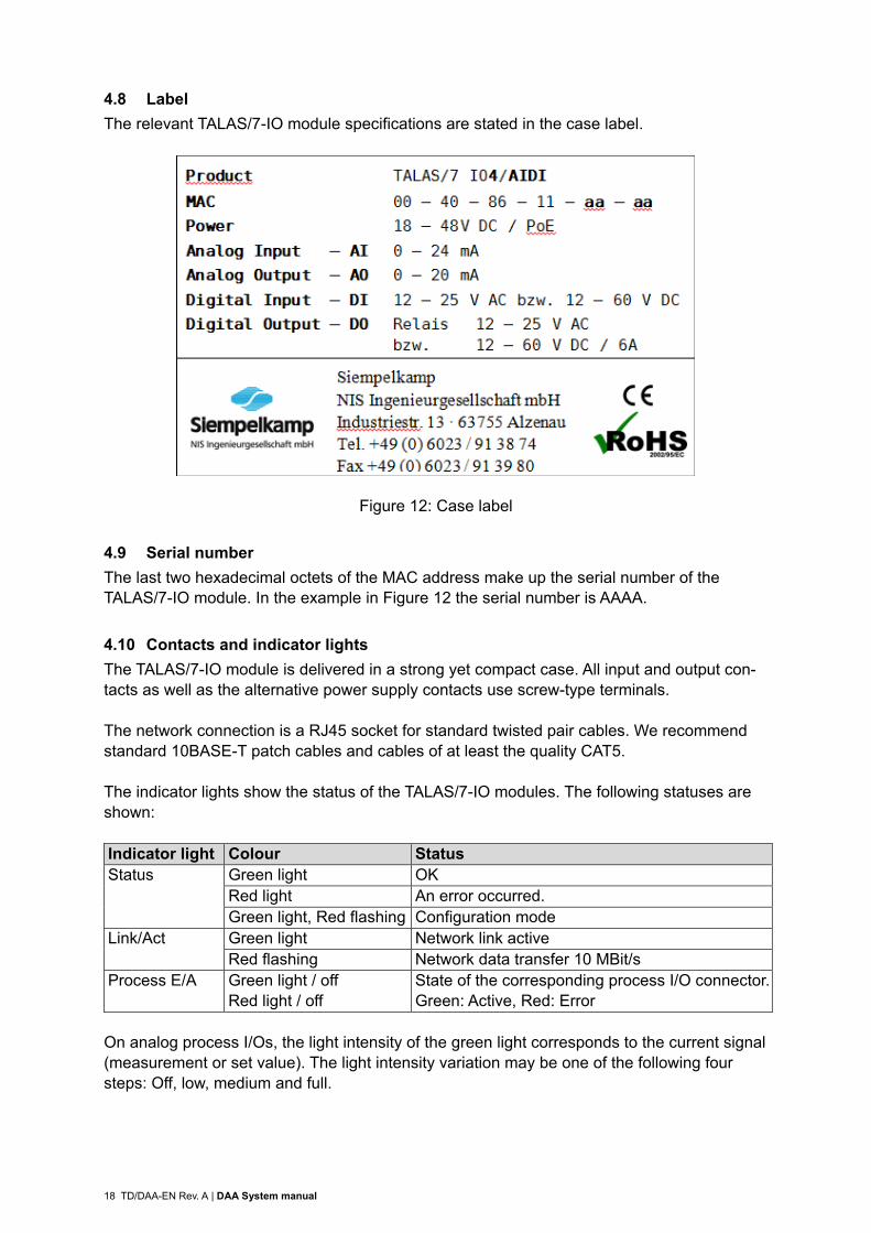
4.8 Label The relevant TALAS/7-IO module specifications are stated in the case label.
Figure 12: Case label
4.9 Serial number The last two hexadecimal octets of the MAC address make up the serial number of the TALAS/7-IO module. In the example in Figure 12 the serial number is AAAA.
4.10 Contacts and indicator lights The TALAS/7-IO module is delivered in a strong yet compact case. All input and output con-tacts as well as the alternative power supply contacts use screw-type terminals. The network connection is a RJ45 socket for standard twisted pair cables. We recommend standard 10BASE-T patch cables and cables of at least the quality CAT5. The indicator lights show the status of the TALAS/7-IO modules. The following statuses are shown: Indicator light Colour Status Status Green light OK
Red light An error occurred. Green light, Red flashing Configuration mode
Link/Act Green light Network link active Red flashing Network data transfer 10 MBit/s
Process E/A Green light / off Red light / off
State of the corresponding process I/O connector. Green: Active, Red: Error
On analog process I/Os, the light intensity of the green light corresponds to the current signal (measurement or set value). The light intensity variation may be one of the following four steps: Off, low, medium and full.
DAA System manual | TD/DAA-EN Rev. A 19
5 Beckhoff Bus Terminals
BK9050 Ethernet TCP/IP “Compact” Bus Coupler for up to 64 Bus Terminals, distance 100 m between hub/switch and Bus Coupler
KL3142 2-channel analog input terminal, 0…20 mA, 16 bit, differential input KL3054 4-channel analog input terminal, 4…20 mA, 12 bit, single-ended KL1404 4-channel digital input terminal, 24 V DC, 2-wire KL1808 8-channel digital input terminal, 24 V DC, 2-wire KL4424 4-channel analog output terminal, 4…20 mA, 12 bit KL4428 8-channel analog output terminal, 4…20 mA, 12 bit KL2404 4-channel digital output terminal, 24 V DC, 2-wire KL2808 8-channel digital output terminal, 24 V DC, 2-wire KL9010 End terminal For further information please refer to http://www.beckhoff.com/BusTerminal/.

20 TD/DAA-EN Rev. A | DAA System manual
6 System requirements
6.1 DAA The evaluation systems may only be used for the purpose of emission monitoring. In the fol-lowing, the system requirements for a PC with only DAA running are specified. Characteristic Configuration Processor minimum Intel Atom Z510
A more powerful CPU may become necessary for “large” parameter-izations.
Operating system Windows XP embedded (32 Bit) Windows 7 Professional (32 Bit und 64 Bit) Windows 8 Professional (32 Bit und 64 Bit) Windows Server 2008 R2 – Standard (64 Bit) Windows Server 2012 R2 – Standard (64 Bit)
RAM minimum 1 GB for Windows XPe/7 (32 Bit) minimum 2 GB for Windows 7 (64 Bit) minimum 4 GB for Server 2008 R2 (64 Bit) minimum 4 GB for Server 2012 R2 (64 Bit)
Hard drive/SSD The more storage space available to DAA, the longer the data can be saved and the more measuring points can be processed. 2 GB storage space shall be considered as minimum.
Network interface yes
6.2 TALAS/7-IO Characteristic Configuration Network interface Yes, the modules are connected with 10BaseT on RJ45.
Please refer to Annex C for IP address configuration in a private network.
Power supply External 24 V DC or PoE (Power over Ethernet)

DAA System manual | TD/DAA-EN Rev. A 21
7 Maintenance
7.1 System messages DAA records errors into its system messages and transmits them to CEM-DAS. It is advised to check these system messages in CEM-DAS in order to assure that DAA is operating as in-tended. Arrays {0} and {1} are identical for all system messages, starting from {3} the arrays are message-specific.
{0} Time of the message {1} Consecutive message number (Modulo 512)
The following system messages are generated by DAA: {0} [{1}] DAA {3} initialization successful
{3} designation of DAA in CEM-DAS The initialization after a restart or reset is done successfully.
{0} [{1}] DAA restart software version {5} / last processing {4 }
{4} Time of last processing {5} Version of DAA3 This message is reported if the reason for restart or reset is known.
{0} [{1}] DAA power failure software version {5} / last processing {4}
{4} Time of last processing {5} Version of DAA3 This message is reported if the reason for restart or reset is unknown.
{0} [{1}] Program exit due to user input
DAA was terminated by user. {0} [{1}] Program exit due to shutdown of operating system
DAA was terminated by operating system. {0} [{1}] Program exit due to shutdown of service
DAA was terminated because DAA service stopped. {0} [{1}] Program reset/exit due to [{3}]
{3} name of the program (see Section 3.2). DAA program was terminated or restarted because it does not work properly.
{0} [{1}] program reset due to user input
DAA program was terminated by user input. {0} [{1}] program reset due to new parameters
DAA reset due to new parameters.
3 Certified installations of CEM-DAS display a version number like 7.2(004). Non certified in-
stallations display a build date like 2017(02) [year(month)].

22 TD/DAA-EN Rev. A | DAA System manual
{0} [{1}] New parameters loaded / Revision {3}{5} subrevision {4} {3} Revision of the parameter. {4} Date of the parameter status. {5} The flag “!” is printed if the CEM-DAS parameter were not released. This message follows the message “program reset due to new parameter”.
{0} [{1}] Hardware-Watchdog not configured
Hardware-Watchdog is not configured for DAA. {0} [{1}] Hardware-Watchdog [{3}] initialized and activated
{3} Designation of the Hardware-Watchdog Hardware-Watchdog is activated properly.
{0} [{1}] Hardware-Watchdog [{3}] error [{4}]
{3} Designation of the Hardware-Watchdog {4} Error number and error message The configured Hardware-Watchdog is unknown, is not initialized or is not activated. Hardware-Watchdog is not available.
{0} [{1}] Hardware-Watchdog [{3}] unknown type
{3} Designation of the Hardware-Watchdog The configured Hardware-Watchdog is unknown.
{0} [{1}] IO-Module [{3}/{4}] Receive error [{5}]
{3} Designation of TALAS/7-IO module {4} IP4 address of the TALAS/7-IO module {5} Error number or error message. Receive error in the UDP telegram form TALAS/7-IO module.
{0} [{1}] IO-Module [{3}/{4}] No more telegrams received
{3} Designation of TALAS/7-IO module {4} IP4 address of the TALAS/7-IO module UDP telegrams form TALAS/7-IO module are received no longer. Either the module is damaged or the network is disconnected.
{0} [{1}] IO-Module [{3}/{4}] Transmit error [{5}]
{3} Designation of TALAS/7-IO module {4} IP4 address of the TALAS/7-IO module {5} Error number or error message. Transmitting to TALAS/7-IO module is corrupted.
{0} [{1}] IO-Module [{3}/{4}] Control point
{3} Designation of TALAS/7-IO module {4} IP4 address of the TALAS/7-IO module Sending control points to the TALAS/7-IO module is corrupted.
{0} [{1}] IO-Module [{3}/{4}] OK
{3} Designation of TALAS/7-IO module {4} IP4 Adresse of the TALAS/7-IO module TALAS/7-IO module is readjusted.

DAA System manual | TD/DAA-EN Rev. A 23
{0} [{1}] Thread [{3}] Receive error [{4}] {3} Designation of the DAA thread {4} Error number or error message Receiving telegrams is corrupted.
{0} [{1}] Thread [{3}] No more telegrams received
{3} Designation of the DAA thread Receiving no more telegrams.
{0} [{1}] Thread [{3}] OK
{3} Designation of the DAA thread The DAA thread is working properly.
{0} [{1}] Error reading parameters
Reading parameter is incorrect. DAA starts without parameter and calculates no data. Reasons:
- No file ‚Transfer7‘ - No file parameter - No file checksum - Corrupted checksum - File paramter corrupted
{0} [{1}] standby system started / no connection
No data processing, only a connection is established. This message is reported if no parameter exist DAA starts with errors.
{0} [{1}] IO-Module [{3}/{4}] Connection established
{3} Designation of TALAS/7-IO module {4} IP4 address of the TALAS/7-IO module TCP network is connected.
{0} [{1}] IO-Module [{3}/{4}] No connection
{3} Designation of TALAS/7-IO module {4} IP4 address of the TALAS/7-IO module
TCP network is disconnected. {0} [{1}] Inspection modus +++ ON +++
Inspection mode for some DAA entities is activated. {0} [{1}] Inspection modus --- OFF ---
Inspection mode for DAA is deactivated. {0} [{1}] Simulation modus +++ ON +++
Simulation mode for DAA is activated. {0} [{1}] Simulation modus --- OFF ---
Simulation mode for DAA is deactivated.

24 TD/DAA-EN Rev. A | DAA System manual
{0} [{1}] Backup system [{3}] Connection established {3} IP4 address of the DAA-backup system DAA-Backup system4 is connected.
{0} [{1}] Backup system [{3}] No Connection
{3} IP4 address of the DAA-backup system DAA-Backup system is not connected. Automatic retries are following. Just a DAA-Master can send this message.
{0} [{1}] Replacement device {3} is being used for device {4}
{3} Designation of the replacement device {4} Designation of the TALAS/7-IO module A prepared and configured device is replaced for the faulty TALAS/7-IO module. The IP address of the faulty device is switched to the replacement.
{0} [{1}] Too many replacement devices {3}
{3} Designation of the replacement device There are more than one replacement device of the same type. DAA cannot decide which device is in use.
{0} [{1}] Too many defect devices {3}
{3} Designation of the defect TALAS/7-IO module There are more than one defect device of the same type. DAA cannot decide which device is to replace.
{0} [{1}] Test modus +++ ON +++
Unreleased revision of parameter is used. {0} [{1}] Test modus --- OFF ---
Released revision is now used. {0} [{1}] System maintenance +++ ON +++
DAA is in test modus or simulation modus. {0} [{1}] System maintenance --- OFF --- Period {3} h:mi
{3} Length of maintenance in ‚h:mi‘. DAA finished test modus or simulation modus.
{0} [{1}] New program version {3}
{3} Version of program ‚1.x (nnn)‘. DAA is running in a new version.
{0} [{1}] Update Program reset due to new program version
A new version is existing. DAA will stop. {0} [{1}] DAA initialization finished
All storaged data are deleted. 4 DAA backup system may be exist in a CEM-DAS replication/redundance system.

DAA System manual | TD/DAA-EN Rev. A 25
{0} [{1}] AMS [{3}] in normal operation {3} Designation of AMS AMS is not in simulation and reference material is not applied.
{0} [{1}] AMS [{3}] in Simulation mode
{3} Designation of AMS At least one measured component is in simulation. Reference material is applied.
{0} [{1}] AMS [{3}] with reference material
{3} Designation of AMS Reference material is applied, but no measured component is in simulation.
{0} [{1}] AMS [{3}] in simulation / with reference material
{3} Designation of AMS At least one measured component is in simulation. Reference material is applied.
{0} [{1}] Update Incorrect new program version
Files of a new version were nor properly transmitted. {0} [{1}] Update Can not start up new program version
New version is corrupted or terminates. {0} [{1}] Update Can not start up new DAA version
New version is corrupted or terminates. {0} [{1}] Replacement device {3} is NOT being used for device {4}
{3} Designation of the replacement device {4} Designation of the TALAS/7-IO module A prepared and configured device cannnot replaced for the faulty TALAS/7-IO module.

26 TD/DAA-EN Rev. A | DAA System manual
7.2 System status Internal system statuses (life signals) are generated in DAA. During parameterization, these can be put out to any digital output of a TALAS/7-IO module. For all system statuses, the “OK” status (i.e. no error, no fault etc.) is put out as 1 (DO set). Hence if no DO is set (0), there is an error or a fault in DAA or CEM-DAS. The following system statuses are available for DAA: System status Meaning CEM-DAS-LDA1 CEM-DAS-LDA2 … CEM-DAS-LDA8
Life signal of CEM-DAS (always parameterized) The significane of these system statuses of CEM-DAS depend on the pa-rameterization of CEM-DAS. They can be used for monitoring the com-munication with a DAA, for remote emissions monitoring or the backup monitoring. These system statuses of CEM-DAS are cyclically transmitted to and evaluated by DAA.
CEM-DAS-OK This system status is 1 when all parameterized system statuses CEM-DAS-LDA1 to CEM-DAS-LDA8 are set to 1. Non-parameterized CEM-DAS system statuses are ignored. This system status is set to 0 if no more new system statuses arrive from CEM-DAS for 5 minutes, since there is no longer a connection to CEM-DAS. Also in this case all CEM-DAS system statuses CEM-DAS-LDA1 to CEM-DAS-LDA8 are set to 0.
RUN-OK All program units5 of DAA have identified no errors or faults. PAR-OK This system status is 1 under the following conditions:
- Parameters are available - The parameters originate from a released revision - There are no new parameters (complete state of the DAA parame-
ters) from a released revision in CEM-DAS. DEV-OK This system status is 1 under the following conditions:
- The data are received by all TALAS/7-IO modules - No errors were detected when checking all control points (DO, AO)
TALAS-OK This system status is 1 under the following conditions: - DEV-OK = 1 - RUN-OK = 1 - Parameters are available - DAA does not run in standby mode6 - DAA does not run in test mode7
SYSTEM-OK This system status is 1 under the following conditions: - DAA-OK = 1 - PAR-OK = 1 - CEM-DAS-OK = 1 - DAA does not run in simulation mode8 - DAA does not run in inspection mode9
If a fatal error occurs during startup of DAA, the program will be stopped. This may occur due to hard disk errors or other problems related to the operating system. 5 See Section 3 6 If an error occurred during startup of DAA or if no parameters could be read in, DAA will
start in standby mode. 7 DAA is in test mode if the available parameters originate from a non-released revision. 8 DAA is in simulation mode if inputs (AIN, BIN) or outputs (AOUT, BOUT) have simulated
values. 9 DAA is in inspection mode if individual measuring points (AMS) are reviewed by a surveyor
(with simulated values, as appropriate).

DAA System manual | TD/DAA-EN Rev. A 27
In standby mode no measured values are acquired and no last slow averages are generated. However, DAA can be accessed via the network and parameters can be loaded. In general, the TALAS/7-IO modules maintain their control points (DO, AO) and do not auto-matically reset them. For this reason, one DO that is used for output of a system status should be set to MONOFLOP mode.
7.3 Replacement devices The parameterization of DAA allows for determining a replacement device with a defined IP4 address. If a TALAS/7-IO module fails, DAA will search for a suitable and parameterized replacement device that was installed for the defective module. If it finds such a replacement device, the IP4 address of the replacement device will be switched to the address of the defective mod-ule. After that, the values of the replacement device are used in DAA. If several TALAS/7-IO modules of the same type fail, the module with the “lowest” IP4 ad-dress will be switched first. A maximum of one replacement device may be installed, since otherwise DAA would not be able to decide which replacement device to use. TALAS/7-IO modules must be located in a private network (see Annex C).
28 TD/DAA-EN Rev. A | DAA System manual
8 Installation
8.1 Introduction This chapter describes initial installation of DAA. For a system update only Section 8.5 has to be performed. If DAA is installed on an CEM-DAS PC, one may jump directly to Section 8.5.
8.2 Preparation A PC with one hard disk with a C partition is sufficient for DAA.
8.3 Windows After configuration of the hard disks the operating system is installed on partition C. After that a user profile “CEM-DAS” is created. All subsequent installations are to be per-formed with this user profile. The password is marked as “always valid”. The user is allocated to the group of administrators.
8.4 Firewall In order to allow receipt of the UDP telegrams of the TALAS/7-IO modules by DAA, a rule has to be parameterized in the Windows firewall. By default, the TALAS/7-IO modules send their UDP to port 49153. If DAA is installed on a separate PC, the firewall must also allow the TCP requests from CEM-DAS on ports 5000 – 5010. For this reason, another incoming rule must be parameter-ized. This rule is not required if DAA is installed on the CEM-DAS PC. By default, remote desktop access is not possible via “public” networks in Windows. The in-coming rule “Properties of remote desktop (TCP incoming)” is only enabled for domain and private networks. For security reasons this rule should also be enabled for a public network. See Annex D for configuration of the firewall.
8.5 DAA DAA is delivered in an installation file that includes the version in its name. For example, the installation file for version 1.2(004) is “cem-daa-1.2(004).exe”. For installation this file must be executed and the files must be installed to “C:\CEM-DAA”. This directory should be set by default. Installation can also be performed when DAA is executed as a program or a service. After in-stallation of the new program files DAA will be stopped and immediately restarted. Before re-start of DAA the new program file will be copied to “daa.exe”. The following message is displayed after the installation file is called up.

DAA System manual | TD/DAA-EN Rev. A 29
Figure 13 Advice for installation
After closing the dialog with OK the next dialog will be schown.
Figure 14 Installation of DAA
Installation starts by clicking UNZIP. The two options “Overwrite files without prompting” and “When done unzipping …” must not be disabled, since otherwise the installation cannot be executed correctly . Further steps will be executed after installation. These are displayed in messages, which re-quire keyboard entries at certain points. When installing DAA on an CEM-DAS PC, several icons for DAA are created in the folder “CEM-DAS”. On a separate PC, these icons will be created directly on the desktop. DAA can be started as a Windows service upon system startup, or as a program after user registration. During the installation the required Windows service (CEM-DAA …) is already registered, but not yet automatically started during system startup (set to “manual”). If DAA shall be started as a Windows service, the start type must be set to “automatic”.
Figure 15 Installed service for DAA

30 TD/DAA-EN Rev. A | DAA System manual
If DAA shall be executed under the user “CEM-DAS”, then this user must be automatically logged in during system startup. Also, the icon “DAA startup” must be stored in its autostart folder. As the DAA program requires administrator rights, user access control must be disabled. After startup of DAA the PC can be automatically locked10, so that no access to the PC is possible after an automatic restart of the system.
8.6 Parameterization Parameterization of DAA is described in the CEM-DAS user manual /1/. The parameteriza-tion interface is integrated into CEM-DAS and can be operated via the web browser.
10 Set environment variable CEMDAA_LOCK_STATION=TRUE
DAA System manual | TD/DAA-EN Rev. A 31
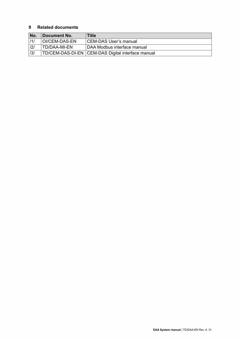
9 Related documents
No. Document No. Title /1/ OI/CEM-DAS-EN CEM-DAS User’s manual /2/ TD/DAA-MI-EN DAA Modbus interface manual /3/ TD/CEM-DAS-DI-EN CEM-DAS Digital interface manual

32 TD/DAA-EN Rev. A | DAA System manual
10 Annex A Dimensions of the TALAS/7-IO modules
10.1 TALAS/7-IO4
10.2 TALAS/7-IO8

DAA System manual | TD/DAA-EN Rev. A 33
11 Annex B Layout of the TALAS/7-IO modules
11.1 TALAS/7-IO8/AI
11.2 TALAS/7-IO8/DI

34 TD/DAA-EN Rev. A | DAA System manual
11.3 TALAS/7-IO8/AIDI
11.4 TALAS/7-IO8/AO

DAA System manual | TD/DAA-EN Rev. A 35
11.5 TALAS/7-IO4/AI, TALAS/7-IO4/DI
11.6 TALAS/7-IO4/AIDI, TALAS/7-IO4/DIDO

36 TD/DAA-EN Rev. A | DAA System manual
11.7 TALAS/7-IO4/AO, TALAS/7-IO4/DO
11.8 TALAS/7-IO4/AODO
DAA System manual | TD/DAA-EN Rev. A 37
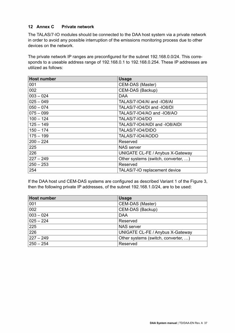
12 Annex C Private network
The TALAS/7-IO modules should be connected to the DAA host system via a private network in order to avoid any possible interruption of the emissions monitoring process due to other devices on the network. The private network IP ranges are preconfigured for the subnet 192.168.0.0/24. This corre-sponds to a useable address range of 192.168.0.1 to 192.168.0.254. These IP addresses are utilized as follows: Host number Usage 001 CEM-DAS (Master) 002 CEM-DAS (Backup) 003 – 024 DAA 025 – 049 TALAS/7-IO4/AI and -IO8/AI 050 – 074 TALAS/7-IO4/DI and -IO8/DI 075 – 099 TALAS/7-IO4/AO and -IO8/AO 100 – 124 TALAS/7-IO4/DO 125 – 149 TALAS/7-IO4/AIDI and -IO8/AIDI 150 – 174 TALAS/7-IO4/DIDO 175 – 199 TALAS/7-IO4/AODO 200 – 224 Reserved 225 NAS server 226 UNIGATE CL-FE / Anybus X-Gateway 227 – 249 Other systems (switch, converter, …) 250 – 253 Reserved 254 TALAS/7-IO replacement device If the DAA host und CEM-DAS systems are configured as described Variant 1 of the Figure 3, then the following private IP addresses, of the subnet 192.168.1.0/24, are to be used: Host number Usage 001 CEM-DAS (Master) 002 CEM-DAS (Backup) 003 – 024 DAA 025 – 224 Reserved 225 NAS server 226 UNIGATE CL-FE / Anybus X-Gateway 227 – 249 Other systems (switch, converter, …) 250 – 254 Reserved
38 TD/DAA-EN Rev. A | DAA System manual
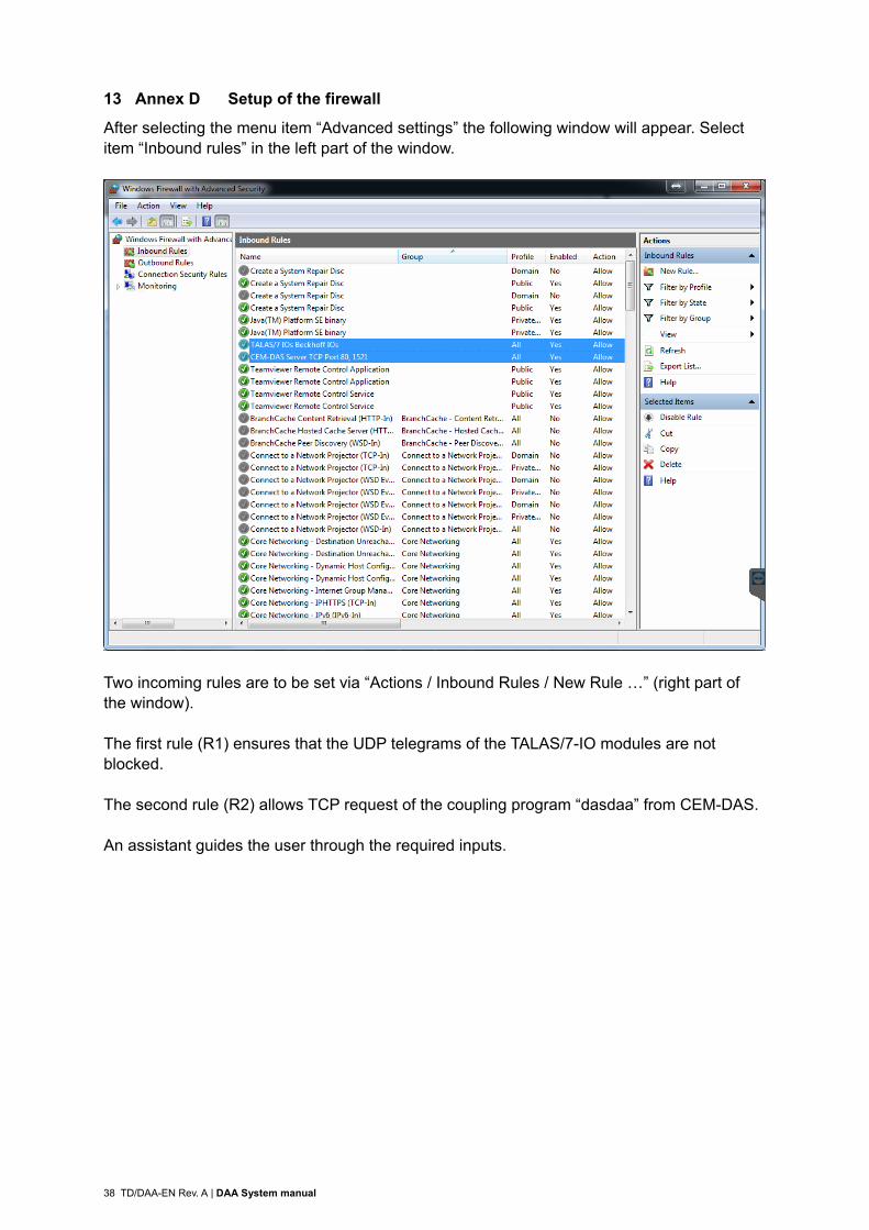
13 Annex D Setup of the firewall
After selecting the menu item “Advanced settings” the following window will appear. Select item “Inbound rules” in the left part of the window.
Two incoming rules are to be set via “Actions / Inbound Rules / New Rule …” (right part of the window). The first rule (R1) ensures that the UDP telegrams of the TALAS/7-IO modules are not blocked. The second rule (R2) allows TCP request of the coupling program “dasdaa” from CEM-DAS. An assistant guides the user through the required inputs.

DAA System manual | TD/DAA-EN Rev. A 39
Select PORT and click NEXT>
Select UDP for rule R1 and enter specific local port 49153. Select TCP for rule R2 and enter port range 5000 – 5010. Click NEXT>

40 TD/DAA-EN Rev. A | DAA System manual
Select “ALLOW THE CONNECTION” and click NEXT>.
Select all three items and click NEXT>

DAA System manual | TD/DAA-EN Rev. A 41
Enter name and description and complete the rule by clicking FINISH.
For rule R1 enter the name and description as shown above.
For rule R2 enter “DAA – CEM-DAS” as the name and “Enable port range 5000-5010 for CEM-DAS” as description.
It is important that the rule is “active” and the connection is allowed. Name and description are for information only.
For rule R1 it is important that port 49153 and protocol UDP are entered. In addition, all re-mote ports (= TALAS/7-IO modules) must be selected.
For rule R2 it is important that port range 5000 – 5010 and protocol TCP are entered and that all remote ports (= CEM-DAS) are selected.

42 TD/DAA-EN Rev. A | DAA System manual
Setup for Remote Desktop Access
By default, the remote desktop is only enabled for a network of the type “domain” and “pri-vate”. If the network type is “public”, remote desktop access to the PC is not possible.
For this reason the incoming rule “Remote desktop properties (TCP incoming)” shall also be enabled for public networks.


Contact
TD
/DA
A-E
N R
ev.
A 0
6.2
017
ABB Limited
Industrial Automation
Howard Road, St. Neots
Cambridgeshire, PE19 8EU
United Kingdom
Phone: +44 870 600 6122
Fax: +44 1480 213 339
ABB Pte. Ltd.
Industrial Automation
2 Ayer Rajah Crescent
139935 Singapore, Singapore
Phone: +65 6773 5961
Fax: +65 6778 0222
ABB Engineering Ltd.
Industrial Automation
10 Jiuxianqiao Lu
100015 Beijing, China
Phone: +86 10 84566688 Ext. 6217
Fax: +86 10 84567650
ABB Inc.
Industrial Automation
3700 W Sam Houston Parkway South,
Suite 600, Houston, TX 77042, USA
Phone: +1 713 587 8000
www.abb.com/analytical
ABB Australia Pty Limited
Industrial Automation
Bapaume Road
2170 Moorebank
New South Wales, Australia
Phone: +61 2 9821 0968
Fax: +61 2 9400 7050
ABB Ltd.
Industrial Automation
14 Mathura Road
121003 Faridabad, Haryana, India
Phone: +91 129 2279627
Fax: +91 129 2279692
ABB Automation GmbH
Industrial Automation
Stierstaedter Strasse 5
60488 Frankfurt am Main, Germany
Fax: +49 69 7930-4566
E-mail: [email protected]
Note
We reserve the right to make technical changes or
modify the contents of this document without prior
notice. With regard to purchase orders, the agreed
particulars shall prevail. ABB does not accept any
responsibility whatsoever for potential errors or
possible lack of information in this document.
We reserve all rights in this document and in the
subject matter and illustrations contained therein.
Any reproduction, disclosure to third parties or
utilization of its contents – in whole or in parts – is
forbidden without prior written consent of ABB.
Copyright © 2017 ABB
All rights reserved
Sales Service
![DAA MID2 [UandiStar.org]](https://static.fdocuments.net/doc/165x107/545a7372af7959755d8b5b4b/daa-mid2-uandistarorg.jpg)