Dash8-200/300 - Auxiliary Power UnitSYSTEM DESCRIPTION General The auxiliary power unit (APU) is a...
9
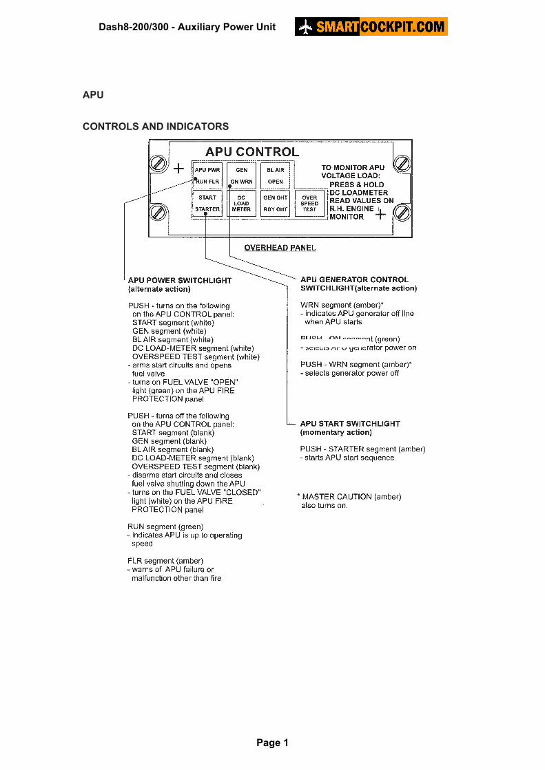
APU CONTROLS AND INDICATORS Dash8-200/300 - Auxiliary Power Unit Page 1
Transcript of Dash8-200/300 - Auxiliary Power UnitSYSTEM DESCRIPTION General The auxiliary power unit (APU) is a...
APU
CONTROLS AND INDICATORS
Dash8-200/300 - Auxiliary Power Unit
Page 1
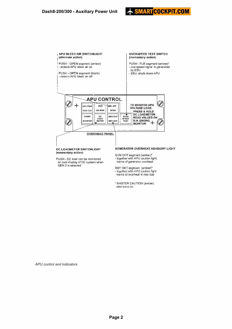
APU control and indicators
Dash8-200/300 - Auxiliary Power Unit
Page 2

APU controls and indicators
closed
Dash8-200/300 - Auxiliary Power Unit
Page 3

SYSTEM DESCRIPTION
General
The auxiliary power unit (APU) is a gas turbine engine, located in the rear equipment bay in the aft fuselage. It supplies air and electrical power to the aircraft on the ground. It can be used to assist aircraft engine starts. The APU engine drives a DC starter-generator, which provides 28 VDC to the right main feeder bus. The APU also delivers bleed air for the air-conditioning packs and the airframe de-icing system. An electronic sequence unit (ESU) located on the right side of the rear accessory compartment provides automatic control of automatic start sequencing, running, and other aspects of APU operation. The APU cannot be operated in flight. ‘Weight-off-wheels’ signals from the PSEU will shutdown the APU if take-off is attempted with the unit operating. The FLR annunciator subsequently illuminates. NOTE: Minimise operation of the APU during ground de-icing operations. Ingestion of
glycol-based de-icing fluid may cause damage to the APU. However, certain de-icing procedures at remote positions (no external power unit available) imply engine shutdown before de-icing takes place. To avoid a subsequent battery start, the APU may be used with the BLEED OFF. De-icing personnel should be instructed not to spray any fluid directly into the APU air inlet.
Dash8-200/300 - Auxiliary Power Unit
Page 4
APU operation
Start
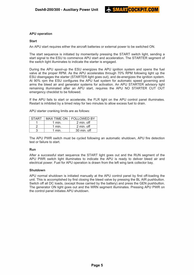
An APU start requires either the aircraft batteries or external power to be switched ON. The start sequence is initiated by momentarily pressing the START switch light, sending a start signal to the ESU to commence APU start and acceleration. The STARTER segment of the switch light illuminates to indicate the starter is engaged. During the APU spool-up the ESU energizes the APU ignition system and opens the fuel valve at the proper RPM. As the APU accelerates through 70% RPM following light up the ESU disengages the starter (STARTER light goes out), and de-energizes the ignition system. At 90% rpm the ESU configures the APU fuel system for automatic speed governing and arms the bleed air and generator systems for activation. An APU STARTER advisory light remaining illuminated after an APU start, requires the APU NO STARTER CUT OUT emergency checklist to be followed. If the APU fails to start or accelerate, the FLR light on the APU control panel illuminates. Restart is inhibited by a timed relay for two minutes to allow excess fuel to drain. APU starter cranking limits are as follows:
START MAX TIME ON FOLLOWED BY
1 1 min. 2 min. off
2 1 min. 2 min. off
3 1 min. 30 min. off
The APU PWR switch must be cycled following an automatic shutdown, APU fire detection test or failure to start. Run
After a successful start sequence the START light goes out and the RUN segment of the APU PWR switch light illuminates to indicate the APU is ready to deliver bleed air and electrical power. Fuel for APU operation is drawn from the left wing tank collector bay. Shutdown
APU normal shutdown is initiated manually at the APU control panel by first off-loading the unit. This is accomplished by first closing the bleed valve by pressing the BL AIR pushbutton. Switch off all DC loads, (except those carried by the battery) and press the GEN pushbutton. The generator ON light goes out and the WRN segment illuminates. Pressing APU PWR on the control panel initiates APU shutdown.
Dash8-200/300 - Auxiliary Power Unit
Page 5

APU overspeed protection
Automatic protection from APU gas generator overspeed is provided by internal, electronic overspeed sensing circuits. When these circuits detect an overspeed, the FLR segment of the APU PWR switch light (along with the APU caution light) illuminates while initiating an immediate APU shutdown sequence. APU fire protection
A fully automatic fire detection/extinguishing system (independent from the engine system) is provided for the APU. The system monitors the APU hot section and exhaust. When the detection system senses a fire or overheat condition, (any point of the loop
exposed to temperatures above 360-440� F) it illuminates a red FIRE warning light on the APU fire protection panel along with the APU caution light. At the same time an automatic signal commences APU shutdown. Following the detection of a fire/overheat condition and the shutdown of the APU, a relay closes to detonate the discharge cartridge of the fire extinguisher. Detonation of the cartridge ruptures the seal of the discharge valve, releasing the bottle contents. If the APU fire extinguisher does not discharge automatically (BTL light illuminated), the bottle can be discharged manually from the guarded EXTG switch on the APU fire protection panel. NOTE: Once the bottle has been discharged, APU restarting is prevented by
interlocking fire protection circuits until the bottle is recharged.
Dash8-200/300 - Auxiliary Power Unit
Page 6
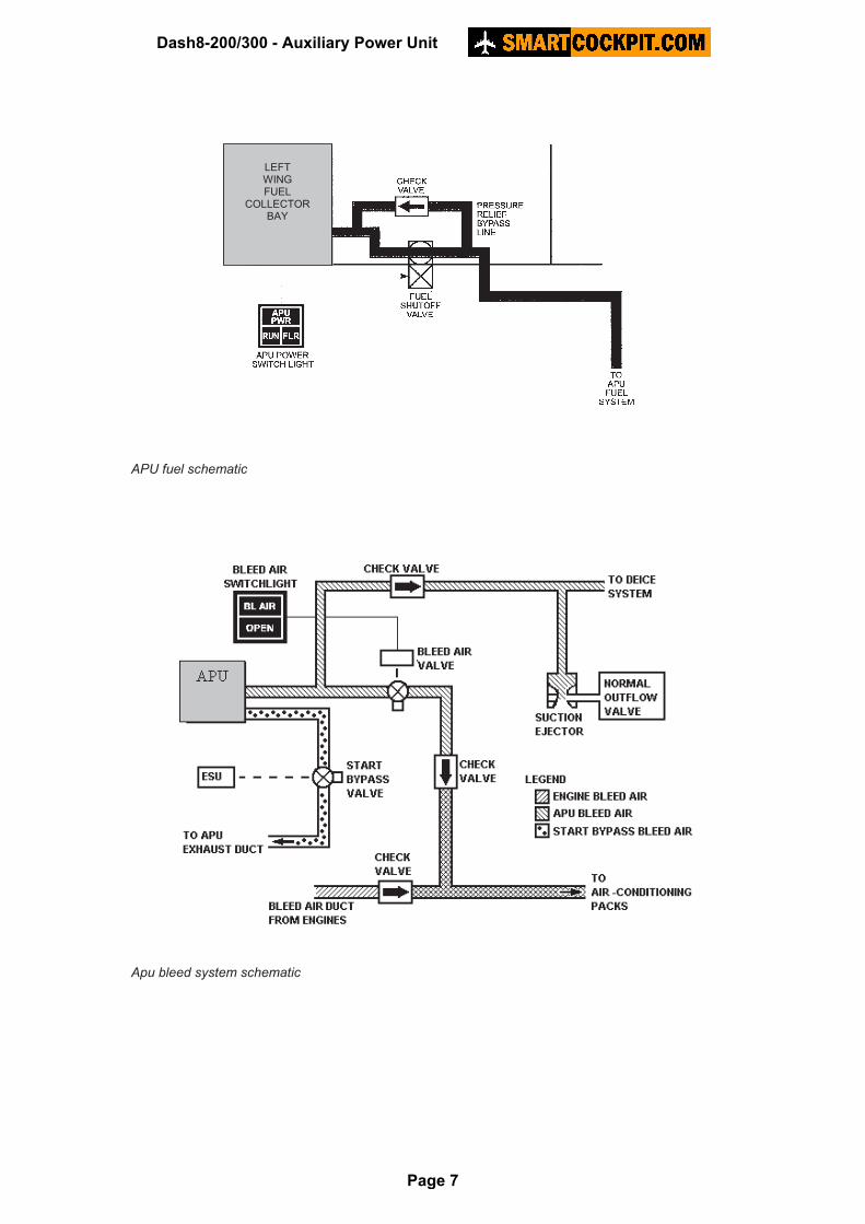
APU fuel schematic Apu bleed system schematic
LEFT WING FUEL
COLLECTOR BAY
Dash8-200/300 - Auxiliary Power Unit
Page 7
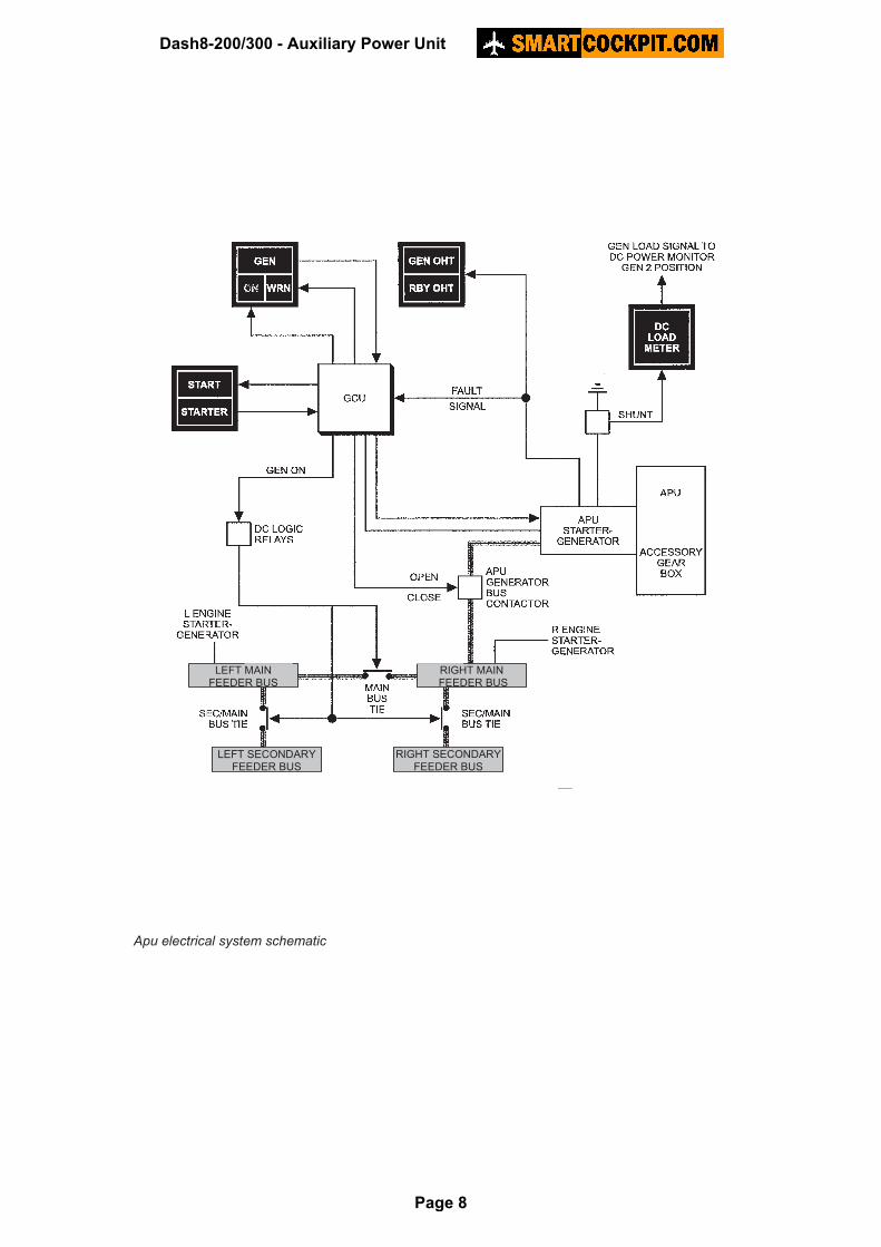
Apu electrical system schematic
LEFT MAIN FEEDER BUS
RIGHT MAIN FEEDER BUS
LEFT SECONDARY FEEDER BUS
RIGHT SECONDARY FEEDER BUS
Dash8-200/300 - Auxiliary Power Unit
Page 8
NON-NORMAL INDICATIONS AND OPERATION
Caution lights
APU
Indicates APU fault, APU fire or compartment overheat.
Applicable ECL APU FIRE or APU failure.
Remarks Also illuminates during overspeed and fire test, and after start sequence when APU generator becomes available.
Dash8-200/300 - Auxiliary Power Unit
Page 9