DARSHAN INSTITUTE OF ENGINEERING & TECHNOLOGY …
71
DARSHAN INSTITUTE OF ENGINEERING & TECHNOLOGY RAJKOT GEOTECHNICAL ENGINEERING (3130606) LAB MANUAL DEGRRE CIVIL ENGINEERING SEMESTER III Name of Student Roll No Enrollment No Class Department of Civil Engineering Geotechnical Engineering Laboratory Darshan Institute of Engineering and Technology Rajkot
Transcript of DARSHAN INSTITUTE OF ENGINEERING & TECHNOLOGY …

DARSHAN INSTITUTE
OF
ENGINEERING & TECHNOLOGY RAJKOT
GEOTECHNICAL ENGINEERING
(3130606)
LAB MANUAL
DEGRRE CIVIL ENGINEERING
SEMESTER III
Name of Student
Roll No
Enrollment No
Class
Department of Civil Engineering
Geotechnical Engineering Laboratory
Darshan Institute of Engineering and
Technology Rajkot

INDEX
Sr.
No Name of Experiment
Page
No. Date Sign
Physical / Index Property Tests on Soils
1. Grain Size Distribution - Sieve Analysis 3
2. Determination of Atterberg limits of fine-grained soils --
A) Liquid Limit Test (Casagrande Method) 7
B) Plastic Limit Test 12
C) Shrinkage Limit Test 15
3. Determination Of In Situ Dry Density --
A) Core Cutter Method 20
B) Sand Replacement Method 23
Engineering Property Tests on Soils
4. Determination of Coefficient of Permeability of Soils
A) Constant Head Permeability Test 26
B) Variable/Falling Head Permeability Test 29
5. Determination of compaction characteristics of soils --
A) Compaction Test (Light & Heavy Compaction Test) 32
6. Box Shear Test (Direct Shear Test) 35
7. Laboratory Vane Shear Test 39
8. Unconfined Compression Test 42
9. Triaxial Test 46
10. Consolidation Test 51
11. Standard Penetration Test (SPT) 59
12. California Bearing Ratio Test (CBR) 64

3 Darshan Institute of Engineering & Technology, Rajkot
DEPARTMENT OF CIVIL ENGINEERING
3130606- GEOTECHNICAL ENGINEERING LAB MANUAL
EXPERIMENT: 1.
GRAIN SIZE DISTRIBUTION - SIEVE ANALYSIS (IS: 2720 PART- 4)
OBJECTIVE:
To determine grain size distribution for given soil sample by sieve analysis.
NEED AND SCOPE
The grain size analysis is widely used in classification of soils. The data obtained
from grain size distribution curves is used in the design of filters for earth dams and
to determine suitability of soil for road construction, air field etc. Information
obtained from grain size analysis can be used to predict soil water movement
although permeability tests are more generally used.
APPARATUS:
Balance: Sensitive to 0.1% of the weight of sample to be weighed.
IS Sieves: 4.75mm, 2.00mm, 1.00mm, 600 µ, 425 µ, 300 µ, 150 µ, to 75 µ.
Brushes - sieve brushes and a wire brush or similar stiff brush.
Mortar with a Rubber Covered Pestle
Mechanical Sieve Shaker (Optional), Riffle & Pan.
Sieves Set Retained Material on Sieve

4 Darshan Institute of Engineering & Technology, Rajkot
DEPARTMENT OF CIVIL ENGINEERING
3130606- GEOTECHNICAL ENGINEERING LAB MANUAL
Preparation of Sample:
The soil sample received from the field shall be prepared as-specified in IS: 2720
(Part I)-1983. The soil fractions retained on and passing 4.75-mm IS Sieve shall
be taken separately for the analysis.
Mass of Soil Required for Sieve Analysis
PROCEDURE:
Analysis by Wet Sieving - The portion of the soil passing 4.75-mm IS Sieve obtained
as given in shall be oven-dried at 105 to 110°C. The oven-dried material shall then
be riffled so that a fraction of convenient mass is obtained. This shall be about 200 g
if a substantial proportion of the material only, just passes the 4.75-mm IS Sieve or
less if the largest size is smaller. The fraction shall be weighed to 0. 1 percent of its
total mass and the mass recorded. The riffled and weighed fraction shall be spread
out in the large tray or bucket and covered with water.
Two grams of sodium hexametaphosphate or one gram of sodium hydroxide and one
gram of sodium carbonate per litter of water used should then be added to the soil.
The mix should be thoroughly stirred and left for soaking.
The soil soaked specimen should be washed thoroughly over the nest of sieves,
nested in order of their fineness with the finest sieve (75-micron IS Sieve) at the
bottom. Washing shall be continued until the water passing each sieve is substantially
clean. Care shall be taken to see that the sieves are not overloaded in the process.
Maximum Size of Material Present In
Substantial
Quantities in (mm)
Mass To Be Taken For Test In
(kg)
75 60
40 25
25 13
19 6.5
12.5 3.5
10 1.5
6.5 0.75
4.75 0.4

5 Darshan Institute of Engineering & Technology, Rajkot
DEPARTMENT OF CIVIL ENGINEERING
3130606- GEOTECHNICAL ENGINEERING LAB MANUAL
The fraction retained on each sieve should be emptied carefully without any loss of
material in separate trays. Oven dried at 105 to 110°C and each fraction weighed
separately and the masses recorded.
Alternatively, the soaked soil specimen may be washed on the 75-micron IS Sieve
until the water passing the sieve is substantially clean. The fraction retained on the
sieve should be tipped without loss of material in a tray, dried in the oven and sieved
through the nest of sieves, either by hand or by using mechanical sieve shaker. The
fraction retained on each sieve should be weighed separately and the masses
recorded.
Make a grain size distribution curve by plotting sieve size on log scale and percent
finer on ordinary scale
Read off the sizes corresponding to 60%, 30% and 10% finer. Calculate the
uniformity coefficient (Cu) and the curvature coefficient (Cc) for the soil.
OBSERVATION TABLE:
Weight of soil sample taken for the test W = gm.
Sieve Size
(mm)
Soil Retained
(gm)
Percent
Retained (%)
Cumulative
Percent Retained (%)
Percent Finer
(%)
4.75 mm
2.00 mm
1.00 mm
600 µ
425 µ
300 µ
150 µ
75 µ
Pan

6 Darshan Institute of Engineering & Technology, Rajkot
DEPARTMENT OF CIVIL ENGINEERING
3130606- GEOTECHNICAL ENGINEERING LAB MANUAL
Particle Size Distribution Curve
D60 = mm
D30 = mm
D10 = mm
Coefficient of Uniformity CU = D60/D10 = .
Coefficient of Curvature CC = (D30)2 / (D60 × D10) = .
CONCLUSION:
Particle Type %
Silt and Clay
Sand
Gravel
Types of Soil

7 Darshan Institute of Engineering & Technology, Rajkot
DEPARTMENT OF CIVIL ENGINEERING
3130606- GEOTECHNICAL ENGINEERING LAB MANUAL
EXPERIMENT: 2. A
ATTERBERG LIMITS OF FINE-GRAINED SOIL
LIQUID LIMIT BY CASAGRANDE METHOD (IS: 2720 Part 5)
OBJECTIVE:
To determination liquid limit of given soil sample by Casagrande method.
NEED AND SCOPE:
Liquid limit is significant to know the stress history and general properties of the soil
met with construction. From the results of liquid limit the compression index may be
estimated. The compression index value will help us in settlement analysis. If the
natural moisture content of soil is closer to liquid limit, the soil can be considered as
soft if the moisture content is lesser than liquids limit, the soil can be considered as soft
if the moisture content is lesser than liquid limit. The soil is brittle and stiffer.
APPARATUS:
Mechanical Liquid Limit Device - It shall conform to IS: 9259-1979.
Grooving Too-It shall conform to IS: 9259- 1979.
Porcelain Evaporating Dish - about 12 to 15 cm in diameter.
Flat Glass Plate-10 mm thick and about 45 cm square or larger (alternative to
porcelain evaporating dish for mixing soil with water).
Spatula-flexible, with the blade about 8 cm long and 2 cm wide (for mixing soil and
water in the porcelain evaporating dish).
Palette Knives-two, with the blade about 20 cm long and 3 cm wide (for mixing soil
and water on the flat glass plate).
Balance-sensitive to 0.01 g.
Oven-thermostatically controlled with interior of non-corroding material to maintain
the temperature between 105 and 110°C.
Wash Bottle or Beaker-containing distilled water containers-air-tight and non-
corrodible for determination of moisture content.

8 Darshan Institute of Engineering & Technology, Rajkot
DEPARTMENT OF CIVIL ENGINEERING
3130606- GEOTECHNICAL ENGINEERING LAB MANUAL
Apparatuses and filling sample in cup
Groove in Soil Sample
SOIL SAMPLE:
A sample weighing about 120 g shall be taken from the thoroughly mixed portion of
material passing 425- micron IS Sieve is IS: 460 (Part I)-19781 obtained in
accordance with IS: 2720 (Part I)-1983.

9 Darshan Institute of Engineering & Technology, Rajkot
DEPARTMENT OF CIVIL ENGINEERING
3130606- GEOTECHNICAL ENGINEERING LAB MANUAL
PROCEDURE:
About 120 g of the soil sample passing 425-micron IS Sieve shall be mixed thoroughly
with distilled water in the evaporating dish or on the flat glass to form a uniform paste.
The paste shall have a consistency that will require 30 to 35 drops of the cup to cause
the required closure of the standard groove. In the case of clayey soils, the soil paste
shall be left to stand for a sufficient time (24 hours) so as to ensure uniform distribution
of moisture throughout the soil mass.
The soil should then be re-mixed thoroughly before the test. A portion of the paste shall
be placed in the cup above the spot where the cup rests on the base, squeezed down and
spread into position, with as few strokes of the spatula as possible and at the same time
trimmed.
A depth of 1 cm at the point of maximum thickness, returning the excess soil to the
dish. The soil in the cup shall be decided by firm strokes of the grooving tool along the
diameter through the center line of the cam follower so that a clean, sharp groove of the
proper dimensions is formed.
The cup shall be fitted and dropped by turning the crank at the rate of two revolutions
per second until the two halves of the soil cake come in contact with bottom of the
groove along. A distance of about 12 mm. This length shall be measured with ‘the end
of the grooving tool or a ruler. The number of drops required to cause the grove close
for the length of 12 mm shall be recorded. A little extra of the soil mixture shall be
added to the cup and mixed with the soil in the cup. The pat shall be made in the cup
and the test repeated.
In no case shall dried soil be added to the thoroughly mixed soil that is being tested and
in, this clause shall be repeated until two consecutive runs give the same under of drops
for closure of the groove.
A representative slice of soil approximately the width of the spatula, extending from
about edge to edge of the soil cake at right angle to the groove and including that portion
of the groove in which the soil flowed together. Shall be taken in a suitable container
and its moisture content expressed as a percentage of the oven-dry weight otherwise
determined as described in IS: 2720 (Part 2)-1973. The remaining soil in the cup shall

10 Darshan Institute of Engineering & Technology, Rajkot
DEPARTMENT OF CIVIL ENGINEERING
3130606- GEOTECHNICAL ENGINEERING LAB MANUAL
be transferred to the evaporating dish and the cup and the grooving tool cleaned
thoroughly.
The operations shall be repeated for at least three more additional trials (minimum of
four in all), with the soil collected in the evaporating dish or flat glass plate, to which
sufficient water has been added to bring the soil to a more fluid condition. In each case,
the number of blows shall be recorded and the moisture content determined as before.
The specimens shall be of such consistency that the number of drops required to close
the groove shall be not less than 15 or not more than 35 and the points on the flow curve
are evenly distributed in this range. The test should proceed from the drier (more drops)
to the wetter (less drops) condition of the soil. The test may also be conducted from the
wetter to the drier condition provided drying is achieved by kneading the wet soil and
not by adding dry soil.
LIQUID LIMIT (WL):
A flow curve shall be plotted on semi-logarithmic graph representing water content on
the arithmetical scale and the number of drops on the logarithmic scale. The flow curve
is a straight line drawn as nearly as possible through the four or more plotted points.
The moisture content corresponding to 25 drops as read from the curve shall be rounded
off to the nearest whole number and reported as the liquid limit of the soil.
OBSERVATION TABLE:
Sample 1 2 3 4 5
Number of drop
Container number
Container Weight
Weight of cont. + wet soil, g
Weight of cont. +oven dry soil, gm
Weight of water
Weight of oven dry sample
Moisture content

11 Darshan Institute of Engineering & Technology, Rajkot
DEPARTMENT OF CIVIL ENGINEERING
3130606- GEOTECHNICAL ENGINEERING LAB MANUAL
Liquid limit of given soil sample(WL) = %
CONCLUSION:

12 Darshan Institute of Engineering & Technology, Rajkot
DEPARTMENT OF CIVIL ENGINEERING
3130606- GEOTECHNICAL ENGINEERING LAB MANUAL
EXPERIMENT: 2. B
PLASTIC LIMIT TEST (IS: 2720 Part 5)
OBJECTIVE:
To determine the plastic limit of the soil sample and to calculate plasticity index,
Toughness index of fine-grained soil.
APPARATUS:
Porcelain Evaporating Dish about 12 cm in diameter.
Flat Glass Plate - 10 mm thick and about 45 cm square or larger.
Spatula - flexible, with the blade about 8 cm long and 2 cm wide. Or Palate Knives-
two, with the blade about 20cm long and 3 cm wide (for use with flat glass plate for
mixing soil and water).
Surface for Rolling - ground-glass plate 20 × 15cm. Containers - air-tight to determine
moisture content.
Balance - sensitive to 0.01 g.
Oven - thermostatically controlled with interior of no corroding material to maintain
the temperature between 105 and 110 ̊ C.
Rod-3 mm in diameter and about 110 cm long.
SOIL SAMPLE
A sample weighing about 20 g from the thoroughly mixed portion of the material
passing 425-micron IS Sieve, obtained in accordance with IS -2720 (Part l)-1983 shall
be taken

13 Darshan Institute of Engineering & Technology, Rajkot
DEPARTMENT OF CIVIL ENGINEERING
3130606- GEOTECHNICAL ENGINEERING LAB MANUAL
PROCEDURE
1. Use the remaining (from liquid limit) soil from the porcelain dish.
2. Take about 10 gm of the soil mass in the hand, form a ball, and roll it between the palm
or the fingers and the glass plate using complete motion of the hand forward and
reverse.
3. Apply only sufficient pressure to make a soil thread, and continue rolling until a thread
of 3 mm diameter is formed. Comparison can be made with the metal rod.
4. If the diameter becomes less than 3 mm without cracking, turn the soil into a ball again,
and re-roll. Repeat this remoulding and rolling process until the thread starts just
crumbling at a diameter of 3 mm.
5. Gather the pieces of crumbled thread and place them in a moisture can for determining
water content.
6. Repeat steps 2 to 5 at least two more times with fresh samples of 10 gm each.
Process of Plastic Limit Test

14 Darshan Institute of Engineering & Technology, Rajkot
DEPARTMENT OF CIVIL ENGINEERING
3130606- GEOTECHNICAL ENGINEERING LAB MANUAL
OBSERVATION TABLE:
SUMMARY
Liquid
limit
WL
Flow
Index
IF
Plasti
c
limit
Wp
Plasticit
y index
IP=WL-
WP
Toughnes
s index
It=IP/IF
Liquidity
index
IL=(W-
WP)/IP
Consistency
index
IC=(WL-
W)/IP
CONCLUSION:
Plastic limit
Sample 1 2 3 4 5
Container number
Container Weight
Weight of cont. + wet soil, g
Weight of cont. +oven dry soil, g
Weight of water
Weight of oven dry sample
Moisture content

15 Darshan Institute of Engineering & Technology, Rajkot
DEPARTMENT OF CIVIL ENGINEERING
3130606- GEOTECHNICAL ENGINEERING LAB MANUAL
EXPERIMENT: 2. C
SHRINKAGE LIMIT (IS: 2720 Part- 6)
OBJECTIVE:
To determine the shrinkage limit and calculate the shrinkage ratio for the given soil.
NEED AND SCOPE
Soils which undergo large volume changes with change in water content may be
troublesome. Volume changes may not and usually will not be equal.
To obtain a quantitative indication of how much change in moisture can occur before
any appreciable volume changes occurs
To obtain an indication of change in volume.
The shrinkage limit is useful in areas where soils undergo large volume changes when
going through wet and dry cycles (as in case of earth dams)
APPARATUS:
Evaporating Dish. Porcelain, about 12cm diameter with flat bottom.
Spatula
Shrinkage Dish. Circular, porcelain or non-corroding metal dish (3 nos) having a flat
bottom and 45 mm in diameter and 15 mm in height internally.
Straight Edge. Steel, 15 cmm in length.
Glass cup. 50 to 55 mm in diameter and 25 mm in height, the top rim of which is ground
smooth and level.
Glass plates. Two, each 75 75 mm one plate shall be of plain glass and the other shall
have prongs.
Sieves 2mm and 425- micron IS sieves.
Oven-thermostatically controlled.
Graduate-Glass, having a capacity of 25 ml and graduated to 0.2 ml and 100 cc one
mark flask.
Balance-Sensitive to 0.01 g minimum.

16 Darshan Institute of Engineering & Technology, Rajkot
DEPARTMENT OF CIVIL ENGINEERING
3130606- GEOTECHNICAL ENGINEERING LAB MANUAL
Mercury. Clean, sufficient to fill the glass cup to over flowing 12.Wash bottle
containing distilled water.
Apparatuses of Shrinkage limit
PROCEDURE
Preparation of soil paste
Take about 100 gm of soil sample from a thoroughly mixed portion of the material
passing through 425-micron I.S. sieve.
Place about 30 gm the above soil sample in the evaporating dish and thoroughly mixed
with distilled water and make a creamy paste.
Use water content somewhere around the liquid limit.
Filling the shrinkage dish
Coat the inside of the shrinkage dish with a thin layer of Vaseline to prevent the soil
sticking to the dish.
Fill the dish in three layers by placing approximately 1/3 rd of the amount of wet soil
with the help of spatula. Tap the dish gently on a firm base until the soil flows over the
edges and no apparent air bubbles exist. Repeat this process for 2nd and 3rd layers also

17 Darshan Institute of Engineering & Technology, Rajkot
DEPARTMENT OF CIVIL ENGINEERING
3130606- GEOTECHNICAL ENGINEERING LAB MANUAL
till the dish is completely filled with the wet soil. Strike off the excess soil and make
the top of the dish smooth. Wipe off all the soil adhering to the outside of the dish.
Weigh immediately, the dish with wet soil and record the weight.
Air- dry the wet soil cake for 6 to 8hrs, until the colour of the pat turns from dark to
light. Then oven- dry the to constant weight at 105˚C to 110˚C say about 12 to 16 hrs.
Remove the dried disk of the soil from oven. Cool it in a desiccators. Then obtain the
weight of the dish with dry sample.
Determine the weight of the empty dish and record.
Determine the volume of shrinkage dish which is evidently equal to volume of the wet
soil as follows. Place the shrinkage dish in an evaporating dish and fill the dish with
mercury till it overflows slightly. Press it with plain glass plate firmly on its top to
remove excess mercury. Pour the mercury from the shrinkage dish into a measuring jar
and find the volume of the shrinkage dish directly. Record this volume as the volume
of the wet soil pat.
Volume of the Dry Soil Pat
Determine the volume of dry soil pat by removing the pat from the shrinkage dish and
immersing it in the glass cup full of mercury in the following manner.
Place the glass cup in a larger one and fill the glass cup to overflowing with mercury.
Remove the excess mercury by covering the cup with glass plate with prongs and
pressing it. See that no air bubbles are entrapped. Wipe out the outside of the glass cup
to remove the adhering mercury. Then, place it in another larger dish, which is, clean
and empty carefully.
Place the dry soil pat on the mercury. It floats submerge it with the pronged glass plate
which is again made flush with top of the cup. The mercury spills over into the larger
plate. Pour the mercury that is displayed by the soil pat into the measuring jar and find
the volume of the soil pat directly.

18 Darshan Institute of Engineering & Technology, Rajkot
DEPARTMENT OF CIVIL ENGINEERING
3130606- GEOTECHNICAL ENGINEERING LAB MANUAL
CALCULATION
First determine moisture contain
Shrinkage Limit 𝑊𝑆 = (𝑊 – (𝑉 − 𝑉0) ∗ (𝛾𝑤
𝑊0))
o Where, W = Moisture content of pat (%)
o V = Volume of wet soil pat in cm3
o V0 = Volume of dry soil pat in cm3
o W0 = Weight of even dry soil pat in gm
Caution
Do not touch the mercury with gold rings.
Observation sheet for shrinkage limit
Sr.
No Determination No. 1 2 3
1 Wt. of container in g W1
2 Wt. of container +wet of soil pet in g (W2)
3 Wt. of container +dry of soil pat in g (W2)
4 Wt. of oven dry soil pat in g (W0)
5 Wt. of water
6 Moisture content (W %)
7 Volume of wet soil pat in cm3
8
Volume of
dry soil pat
in cm3
By Mercury
displacemen
t method
a. Weight of
displaced
Mercury
b. Specific gravity
of Mercury
9 Shrinkage limit(Ws)
10 Shrinkage Ratio (R)

19 Darshan Institute of Engineering & Technology, Rajkot
DEPARTMENT OF CIVIL ENGINEERING
3130606- GEOTECHNICAL ENGINEERING LAB MANUAL
CONCLUSION:

20 Darshan Institute of Engineering & Technology, Rajkot
DEPARTMENT OF CIVIL ENGINEERING
3130606- GEOTECHNICAL ENGINEERING LAB MANUAL
EXPERIMENT: 3. A
IN - SITU DENSITY BY CORE CUTTER METHOD (IS: 2720 Part- 29)
OBJECTIVE:
To determine in - situ density by core cutter method.
APPARATUS:
Cylindrical core cutter
Dolly, Rammer
Balance (1 g accuracy)
Spade
Straight edge knife
Sample extruder
Apparatus for moisture content determination

21 Darshan Institute of Engineering & Technology, Rajkot
DEPARTMENT OF CIVIL ENGINEERING
3130606- GEOTECHNICAL ENGINEERING LAB MANUAL
PROCEDURE
Measure the internal dimensions of the core cutter and weigh it.
Clean and level the site surface where the field density is to be determined.
Place the dolly on the cutter and press both into the soil using the rammer until only
about 15 mm of the dolly protrudes above the surrounding soil surface.
Remove the soil around the cutter with the spade, lift up the cutter, and trim carefully
the top and bottom surfaces of the soil sample.
Clean the outside surface of the cutter and weigh it with the soil.
Remove the soil core from the cutter and take three representative samples in
moisture cans for water content determination.
OBSERVATIONS:
Internal diameter of core cutter, (cm) =
Height of cutter, (cm) =
Volume of cutter, V (cm3) =
Test No. 1 2 3
Mass of core cutter (g), W1
Mass of cutter + soil (g), W2
Mass of moist soil (g), (W2- W1)
Average water content, W (%)
Field bulk density (g/cm3),
Field dry density (g/cm3),
In-situ dry density (Average of the computed
values)

22 Darshan Institute of Engineering & Technology, Rajkot
DEPARTMENT OF CIVIL ENGINEERING
3130606- GEOTECHNICAL ENGINEERING LAB MANUAL
CONCLUSION:

23 Darshan Institute of Engineering & Technology, Rajkot
DEPARTMENT OF CIVIL ENGINEERING
3130606- GEOTECHNICAL ENGINEERING LAB MANUAL
EXPERIMENT: 3. B
IN – SITU DENSITY BY SAND REPLACEMENT METHOD
(IS: 2720 Part- 28)
OBJECTIVE:
To determine in – situ density of field by sand replacement method.
NEED AND SCOPE:
The in situ density of natural soil is needed for the determination of bearing capacity of
soils, for the purpose of stability analysis of slopes, for the determination of pressures
on underlying strata for the calculation of settlement and the design of underground
structures
APPARATUS:
Sand pouring cylinder
Calibrating cylinder
Clean and dry sand
Metal tray with a central circular hole
Balance (1 gm accuracy)
Glass plate, Trowel, Scraper tool
Apparatus for moisture content determination.

24 Darshan Institute of Engineering & Technology, Rajkot
DEPARTMENT OF CIVIL ENGINEERING
3130606- GEOTECHNICAL ENGINEERING LAB MANUAL
PROCEDURE:
An inverted cone forms the base of the sand pouring cylinder, and a shutter at the cone
tip controls the release of sand through a uniform free fall.
First determine the bulk density of the sand to be used in the field. For this, measure the
internal dimensions of the calibrating cylinder so as to obtain its volume. Fill the
pouring cylinder with sand and weigh. Place it concentrically on top of the calibrating
cylinder, and allow sand to run out and fill both the calibrating cylinder and the inverted
conical portion.
To obtain only the mass of sand filling up the conical portion, lift the pouring cylinder
and then weigh with remaining sand. Place it on a glass plate, and allow sand to run
out. Weigh again the pouring cylinder with left over sand.
Calculate the mass of sand that fills up the calibrating cylinder, and from its known
volume, work out the bulk density of the sand for the allowed free fall.
Clean and level the site surface, and place the square tray with a central hole. Excavate
a hole of diameter equal to that of the tray hole and depth equal to about 15 cm. Collect
the excavated soil in the tray, weigh and then take representative samples for water
content determination.
Fill the pouring cylinder with the same sand, place it concentrically over the hole, open
the shutter and allow sand to fill up the hole.
When there is no further movement of sand, close the shutter, remove the cylinder and
weigh it with the remaining sand.

25 Darshan Institute of Engineering & Technology, Rajkot
DEPARTMENT OF CIVIL ENGINEERING
3130606- GEOTECHNICAL ENGINEERING LAB MANUAL
OBSERVATIONS:
Bulk density of sand, = (g/cm3)
Volume of calibrating cylinder, V1 = (cm3)
Mass of sand for filling the calibrating cylinder and cone W1 = (gm)
Mass of sand for filling only the cone, W2 = (gm),
Mass of sand in the calibrating cylinder (g), W3 = W1 – W2 = (gm),
CONCLUSION:
Field Test No.
1
2
3
Mass of pouring cylinder + sand before pouring in
hole (g), W4
Mass of pouring cylinder + sand after pouring in
hole (g), W5
Mass of sand used in the hole (g), W6 = W4 - W5 -
W2
Volume of excavated hole (cm3),
Mass of excavated soil (g), W
Average water content, w (%)
Field bulk density (g/cm3)
Field dry density (g/cm3)
Avg. Field Density

26 Darshan Institute of Engineering & Technology, Rajkot
DEPARTMENT OF CIVIL ENGINEERING
3130606- GEOTECHNICAL ENGINEERING LAB MANUAL
EXPERIMENT: 4. A
CONSTANT HEAD PERMEABILITY TEST (IS: 2720 Part- 17)
OBJECTIVE:
To determine the coefficient of permeability of a soil using constant head apparatus
NEED AND SCOPE:
The knowledge of this property is much useful in solving problems involving yield of
water bearing strata, seepage through earthen dams, stability of earthen dams, and
embankments of canal bank affected by seepage, settlement etc
APPARATUS:
Permeameter mould and accessories
Circular filter papers, Compaction device
Constant head reservoir
Measuring flask
Stop-watch
Test Setup Diagrame of Test Process

27 Darshan Institute of Engineering & Technology, Rajkot
DEPARTMENT OF CIVIL ENGINEERING
3130606- GEOTECHNICAL ENGINEERING LAB MANUAL
Mouls Section Coller Elevation Section Bottom Secion of
mould
PROCEDURE:
Take 2.5 kg of dry soil and prepare it to obtain desired water content.
Apply little grease on to the interior sides of the permeameter mould.
Keep a solid metal plate in the groove of the compaction base plate. Assemble the
base plate, mould and collar. Compact the soil into the mould.
Remove the collar and base plate, and replace the solid metal plate with a porous
stone covered with filter paper.
Trim off excess soil from the top of the mould and place another porous stone with
filter paper on it. Attach the top cap of the permeameter.
Connect a constant head reservoir to the bottom outlet of the mould. Open the air
vent of the top cap, and allow water to flow in and upwards till the soil gets saturated.
Disconnect the reservoir from the bottom outlet and connect it to the top inlet. Close
the air vent and allow water to establish a steady flow.
Collect the water in a measuring flask for a convenient time interval. For similar
time intervals, measure the flow quantity for at least three times.
After the test, measure the temperature of the water.
28 Darshan Institute of Engineering & Technology, Rajkot
DEPARTMENT OF CIVIL ENGINEERING
3130606- GEOTECHNICAL ENGINEERING LAB MANUAL
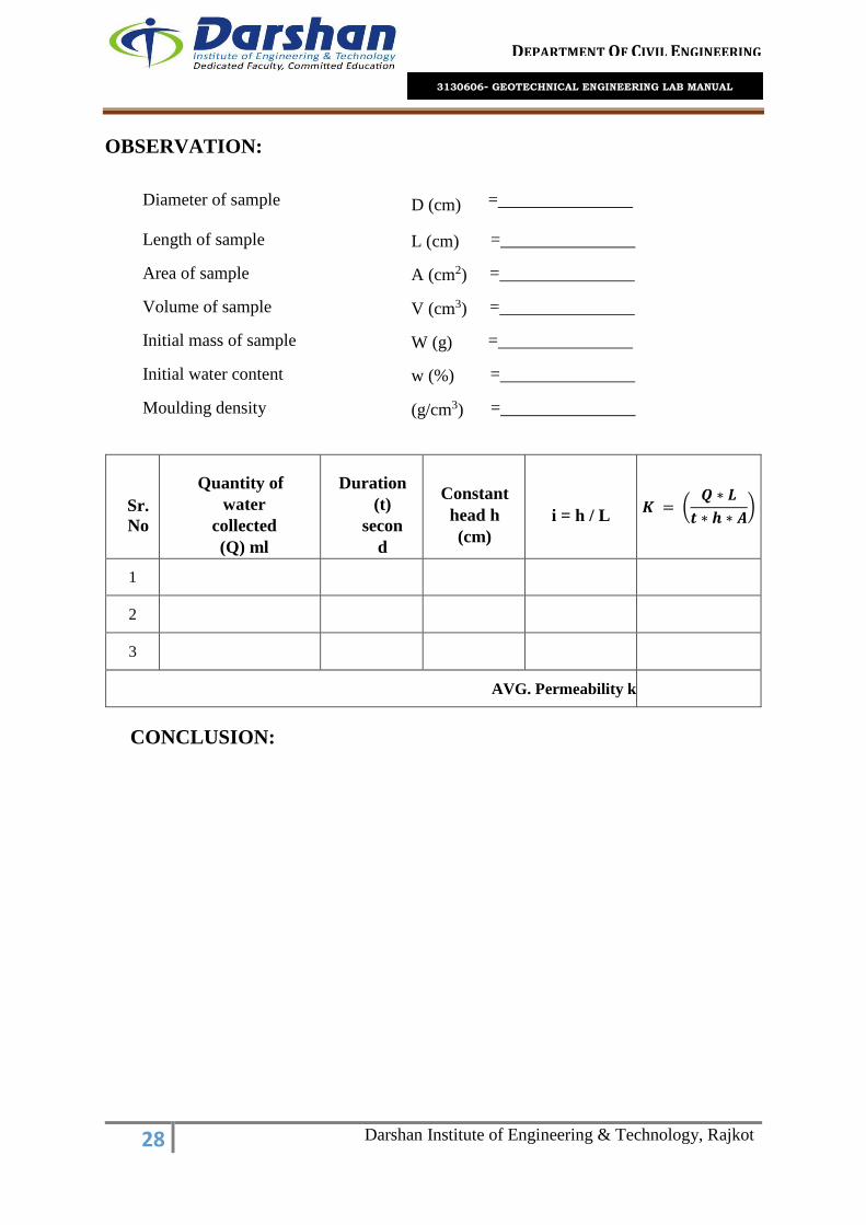
OBSERVATION:
Diameter of sample D (cm) =
Length of sample L (cm) =
Area of sample A (cm2) =
Volume of sample V (cm3) =
Initial mass of sample W (g) =
Initial water content w (%) =
Moulding density (g/cm3) =
Sr.
No
Quantity of
water
collected
(Q) ml
Duration
(t)
secon
d
Constant
head h
(cm)
i = h / L
𝑲 = (𝑸 ∗ 𝑳
𝒕 ∗ 𝒉 ∗ 𝑨)
1
2
3
AVG. Permeability k
CONCLUSION:

29 Darshan Institute of Engineering & Technology, Rajkot
DEPARTMENT OF CIVIL ENGINEERING
3130606- GEOTECHNICAL ENGINEERING LAB MANUAL
EXPERIMENT: 4. B
FALLING HEAD PERMEABILITY TEST (IS: 2720 Part- 4)
OBJECTIVE:
To determine coefficient of permeability of a soil using falling head / variable head
apparatus
NEED AND SCOPE
To estimate ground water flow, to calculate seepage through dams, to find out the rate
of consolidation and settlement of structures, to plan the method of lowering the ground
water table, to calculate the uplift pressure and piping, to design the grouting, And also
for soil freezing tests, to design pits for recharging.
APPARATUS:
Permeameter mould and accessories
Circular filter papers, Compaction device
Graduated glass standpipes along with support frame and clamps
Measuring flask
Stop-watch.

30 Darshan Institute of Engineering & Technology, Rajkot
DEPARTMENT OF CIVIL ENGINEERING
3130606- GEOTECHNICAL ENGINEERING LAB MANUAL
Test Setup
PROCEDURE:
Follow the same steps 1 to 6 as for the constant head test.
Disconnect the reservoir from the bottom outlet and connect a selected standpipe to
the top inlet.
Fill the standpipe with water, close the air vent and allow water to flow.
Open the bottom outlet and record the time interval required for the water surface in
the standpipe to fall between two levels as measured from the centre of the outlet.
Measure time intervals for similar drops in head at least three times after re-filling the
standpipe.
At the end of the test, measure the temperature of the water.

31 Darshan Institute of Engineering & Technology, Rajkot
DEPARTMENT OF CIVIL ENGINEERING
3130606- GEOTECHNICAL ENGINEERING LAB MANUAL
OBSERVATION TABLE:
Diameter of standpipe, d = (cm)
Cross-sectional area of standpipe, a = (cm2)
Test No. 1 2 3
Initial head, h1 (cm)
Final head , h2 (cm)
Time interval in seconds, ( t2 - t1)
Avg. Coefficient of permeability (cm/sec)
CONCLUSION:

32 Darshan Institute of Engineering & Technology, Rajkot
DEPARTMENT OF CIVIL ENGINEERING
3130606- GEOTECHNICAL ENGINEERING LAB MANUAL
EXPERIMENT: 5.
LIGHT & HEAVY PROCTOR COMPACTION TEST
(IS: 2720 Part- 7 & 8)
OBJECTIVE:
To determine the relation between the water content and the dry density of soils using
light/heavy proctor compaction.
APPARATUS:
SampleExtruder (Optional)
Container, Tray or pan, Trowel and spatula, Spoon, Oven, Mould
Balances- capacity of 10 kg and 1 gm sensitive & other of capacity 200 gm and 0.01
gm sensitive
Steel Straightedge - Mixing Tools, Metal Rammer,
PROCEDURE FOR LIGHT COMPACTION:
Obtain a sufficient quantity of air-dried soil and pulverize it. Take about 5 kg of soil
passing through 19 mm sieve in a mixing tray.
Weigh the mould with base plate and apply grease lightly on the interior surfaces. Fit
the collar and place the mould on a solid base.
Add water to the soil to bring its moisture content to about 8% and then mix it
thoroughly using the trowel until the soil gets a uniform color.
For light compaction, compact the moist soil in three equal layers using a rammer of
mass 2.6 kg and having free fall of 31 cm. Distribute the blows evenly, and apply 25
blows in each layer. Ensure that the last compacted layer extends above the collar joint.
Alternatively for heavy compaction, compact the soil with 25 blows per layer, in five
equal layers with a rammer of mass 4.9 kg and 45 cm free fall.
Rotate the collar so as to remove it, trim off the compacted soil flush with the top of the
mould, and weigh the mould with soil and base plate.

33 Darshan Institute of Engineering & Technology, Rajkot
DEPARTMENT OF CIVIL ENGINEERING
3130606- GEOTECHNICAL ENGINEERING LAB MANUAL
Extrude the soil from the mould and collect soil samples from the top, middle and
bottom parts for water content determination. Place the soil back in the tray, add 2%
more water based on the original soil mass, and re-mix as in step 3. Repeat steps 4 and
5 until a peak value of compacted soil mass is reached followed by a few samples of
lesser compacted soil masses.
Calculate the bulk density of each compacted soil specimen.
Calculate the average moisture content of the compacted specimen and then its dry
density.
Plot the dry densities obtained as ordinates against the corresponding moisture contents
as abscissa, draw a smooth compaction curve passing through them, and obtain the
values of maximum dry density (MDD) and optimum moisture content (OMC).
On the same graph, plot a curve corresponding to 100% saturation, calculated from
Where, S = degree of saturation,
Gs = specific gravity of solids,
Ƴw = unit weight of water.
CALCULATIONS:
Bulk Density –γb in g/cc, of each compacted specimen shall be calculated from the
equation:
𝛾𝑏 = ( 𝑀2− 𝑀1
𝑉𝑀)
Where, M1= mass in g of mould and base
M2 = mass in g of mould, base and soil; and
VM = volume in cm3 of mould.

34 Darshan Institute of Engineering & Technology, Rajkot
DEPARTMENT OF CIVIL ENGINEERING
3130606- GEOTECHNICAL ENGINEERING LAB MANUAL
The dry density, γd in g/cc, shall be calculated from the equation:
𝛾𝑑 = (𝛾𝑏
1 + 𝑤/100)
Where, γb = builk density
w = water content of soil (%)
OBSERVATION:
CONCLUSION:
Type of test (Standard/ Modified proctor test)
Volume of mould (cm3) (1000cm3/2250cm3)
No .of Test 1 2 3 4 5
Container no.
Empty weight of container
Container + wet soil(gm)
Container+ dry soil (gm)
Mass of mould (gm)
Mass of mould + compacted soil (gm)
Mass of compacted soil, Wt.(gm)
Bulk density (g/cc)
Average water content w (%)
Dry density (g/cc )
Dry density at 100% saturation (g/cc )
RESULT SUMMARY (after plotting a graph)
Maximum Dry Density… ....................... gm/cc
Optimum Moisture Content… .......................... %

35 Darshan Institute of Engineering & Technology, Rajkot
DEPARTMENT OF CIVIL ENGINEERING
3130606- GEOTECHNICAL ENGINEERING LAB MANUAL
EXPERIMENT: 6.
DIRECT BOX SHEAR TEST (IS: 2720 PART- 13)
OBJECTIVE:
To determine shear strength of given soil sample by direct box shear test.
NEED AND SCOPE:
In many engineering problems such as design of foundation, retaining walls, slab
bridges, pipes, sheet piling, the value of the angle of internal friction and cohesion of
the soil involved are required for the design. Direct shear test is used to predict these
parameters quickly. The laboratory report cover the laboratory procedures for
determining these values for cohesionless soils.
APPARATUS:
The shear box grid plates, porous stones, base plates, and loading pad and water jacket
shall conform to IS: 11229-1985.
Loading Frame, Proving Ring - Force measuring of suitable capacity, fitted with a dial-
gauge accurate to 0.002 mm to measure the shear force.
Micrometer Dial Gauges – Accurate to 0.01 mm. One suitably mounted to measure
horizontal movement and the other suitably mounted to measure the vertical
compression of the specimen.
Sample Trimmer or Core Cutter, Stop Clock, Balance of 1 kg capacity sensitive to 0.1g
PREPARATION OF SPECIMEN:
Undisturbed Specimens - Specimens of required size shall be prepared in accordance
with IS: 2720 (Part I)-1983.
Remoulded Specimens –
Cohesive soils may be compacted to the required density and moisture content, the
sample extracted and then trimmed to required size. Alternatively, the soil may be
compacted to the required density and moisture content directly into the shear box after
fixing the two halves of the shear box together by means of the fixing screws.

36 Darshan Institute of Engineering & Technology, Rajkot
DEPARTMENT OF CIVIL ENGINEERING
3130606- GEOTECHNICAL ENGINEERING LAB MANUAL
Cohesion less soils may be tamped in the shear box itself with the base plate and grid
plate or porous stone as required in place at the bottom of the box.
The cut specimen shall be weighed and trimmings obtained during cutting shall be used to
obtain the moisture content. Using this information, the bulk dry density of the specimen
in the shear box shall be determined
Direct shear apparatus Arrangement of sample in direct shear apparatus
PROCEDURE:
Undrained Test -The shear box with the specimen, plain grid plate over the base plate
at the bottom of the specimen and plain grid plate at the top of the specimen should be
fitted into position in the load frame.
The serrations of the grid plates should be at right angles to the direction of shear the
loading pad should be placed on the top grid plate. The water jacket should be provided
so that the sample does not get dried during the test.

37 Darshan Institute of Engineering & Technology, Rajkot
DEPARTMENT OF CIVIL ENGINEERING
3130606- GEOTECHNICAL ENGINEERING LAB MANUAL
The required normal stress should be applied and the rate of longitudinal
displacement/shear stress application so adjusted that no drainage can occur in the
sample during the test. The upper part of the shear box should be raised such that a gap
of about I mm is left between the two parts of the box.
The test may now be conducted by applying horizontal shear load to failure or to 20
percent longitudinal displacement, whichever occurs first. The shear load readings
indicated by the proving ring assembly and the corresponding longitudinal
displacements should be noted at regular intervals.
CALCULATIONS AND REPORT:
If necessary, the vertical compression, if any, of the soil specimen may be measured to
serve as check to ensure that drainage has not taken place from the soil specimen. At
the end of the test, the specimen should be removed from the box and the final moisture
content measured. A minimum of three (preferably four) tests shall be made on separate
specimens of the same density.
From the calibration chart of the proving ring, the loads corresponding to the load dial
readings obtained during the test should be calculated.
The loads so obtained divided by the corrected cross-sectional area of the specimen
gives the shear stress in the sample. The corrected cross-sectional area shall be
calculated from the following equation:
Corrected area 𝑨 = 𝑨𝟎 ∗ (𝟏 − (𝜹
𝟑))
Where, δ = displacement in cm
Ao = initial area of the specimen in cm2

38 Darshan Institute of Engineering & Technology, Rajkot
DEPARTMENT OF CIVIL ENGINEERING
3130606- GEOTECHNICAL ENGINEERING LAB MANUAL
Performa for recording shear stage
Depth- Size of box(cm)- Mass of soil (gm)-
Rate of strain - Area of box (cm2)- OMC - %
Type of test - Volume of box(cm3)- MDD - gm/cc
Normal stress applied (kg/cm2)- Density of soil(kg/cm3) -
Least count of disp. dial gauge (mm/div.)- Proving ring constant (kg/div.)-
Dial gauge reading
Proving ring
reading
Horizontal
load (Kg)
Shear stress
(Kg/cm2)
Normal stress
(Kg/cm2)
Horizontal dial
gauge
Vertical dial
Gauge
From graph
Cohesion, C (Kg/cm2)
Angle of internal friction, Φ˚
Remarks-
CONCLUSION:

39 Darshan Institute of Engineering & Technology, Rajkot
DEPARTMENT OF CIVIL ENGINEERING
3130606- GEOTECHNICAL ENGINEERING LAB MANUAL
EXPERIMENT: 7.
VANE SHEAR TEST (IS: 2720 PART- 30)
OBJECTIVE
To determine shear strength of a given soil specimen.
NEED AND SCOPE
The structural strength of soil is basically a problem of shear strength.
Vane shear test is a useful method of measuring the shear strength of clay. It is a
cheaper and quicker method. The test can also be conducted in the laboratory. The
laboratory vane shear test for the measurement of shear strength of cohesive soils,
is useful for soils of low shear strength (less than 0.3 kg/cm2) for which triaxial or
unconfined tests cannot be performed. The test gives the undrained strength of the
soil. The undisturbed and remoulded strength obtained are useful for evaluating the
sensitivity of soil.
APPARATUS:
Vane shear apparatus.
Specimen.
Specimen container.
Callipers.
PROCEDURE:
Prepare two or three specimens of the soil sample of dimensions of at least 37.5 mm
diameter and 75 mm length in specimen. (L/D ratio 2 or 3).
Mount the specimen container with the specimen on the base of the vane shear
apparatus. If the specimen container is closed at one end, it should be provided with
a hole of about 1 mm diameter at the bottom.

40 Darshan Institute of Engineering & Technology, Rajkot
DEPARTMENT OF CIVIL ENGINEERING
3130606- GEOTECHNICAL ENGINEERING LAB MANUAL
Gently lower the shear vanes into the specimen to their full length without
disturbing the soil specimen. The top of the vanes should be at least 10 mm below
the top of the specimen. Note the readings of the angle of twist.
Rotate the vanes at a uniform rate say 0.1˚/s by suitable operating the torque
application handle until the specimen fails.
Note the final reading of the angle of twist.
Find the value of blade height in cm.
Find the value of blade width in cm.
Calculations & Observations
Shear strength, 𝑺 =𝑻
(𝝅∗𝑫𝟐)∗((𝑯
𝟐)+(
𝑫
𝟔))
If bottom end is engaged in shearing the soil,
Shear strength, 𝑺 =𝑻
(𝝅∗𝑫𝟐)∗((𝑯
𝟐)+(
𝑫
𝟏𝟐))
Where, s = shear strength of soil in kg/cm2,
T = torque in kg.cm = spring constant/ 180˚* difference,
D = overall diameter of vane in cm,
H = height of vane cm.

41 Darshan Institute of Engineering & Technology, Rajkot
DEPARTMENT OF CIVIL ENGINEERING
3130606- GEOTECHNICAL ENGINEERING LAB MANUAL
Observation table
CONCLUSION:
Sr.
No
Initial
Readin
g (Deg.)
Final
Readin
g (Deg.)
Difference
(Deg.)
T
Kg-
cm
𝑮
=𝟏
(𝝅 ∗ 𝑫𝟐) ∗ ((𝑯𝟐
) + (𝑫𝟔
))
S=TxG
Kg/cm2
Average
'S'
Kg/cm2
Spring
Constant
Kg-cm

42 Darshan Institute of Engineering & Technology, Rajkot
DEPARTMENT OF CIVIL ENGINEERING
3130606- GEOTECHNICAL ENGINEERING LAB MANUAL
EXPERIMENT: 8.
UNCONFINED COMPRESSION TEST (IS: 2720 Part- 10)
OBJECTIVE:
To determine the unconfined compressive strength of clayey soil under controlled
strain condition.
NEED AND SCOPE:
It is not always possible to conduct the bearing capacity test in the field. Sometimes it
is cheaper to take the undisturbed soil sample and test its strength in the laboratory.
Also to choose the best material for the embankment, one has to conduct strength tests
on the samples selected. Under these conditions it is easy to perform the unconfined
compression test on undisturbed and remoulded soil sample. Now we will investigate
experimentally the strength of a given soil sample
APPARATUS:
Compression device of any suitable type
Sample ejector
Strain measuring dial gauge with 0.01 mm graduations
Stopwatch
Oven
Balance
Miscellaneous equipment, such as specimen trimming and curving tools, remolding
apparatus, moisture cans, etc.
Split moulds - 3.5 cm diameter and 7 cm long (or 3.75 cm diameter and 7.5 cm long)

43 Darshan Institute of Engineering & Technology, Rajkot
DEPARTMENT OF CIVIL ENGINEERING
3130606- GEOTECHNICAL ENGINEERING LAB MANUAL
Unconfined compression test machine
PROCEDURE:
Preparation of Test Specimen
Undisturbed cylindrical specimen may be cut from the bigger undisturbed sample
obtained from the field. A wire saw may be used to trim the ends parallel to each other.
Lathe or trimmer may be used to trim the specimen to circular cross-section.
Alternatively, field sample may be obtained directly in a thin sampling tube having the
same internal diameter as the specimen to be tested. The split mould is oiled lightly
from inside and the sample is then pushed out of the tube into the split mould. The split
mould is opened carefully and sample taken is out.
Remoulded sample may be prepared by compacting the soil at the desired water content
and dry density in a bigger mould, and then cut by the sampling tube. Alternatively,
remoulded specimen may be prepared directly in the split mould.

44 Darshan Institute of Engineering & Technology, Rajkot
DEPARTMENT OF CIVIL ENGINEERING
3130606- GEOTECHNICAL ENGINEERING LAB MANUAL
COMPRESSION TEST
Measure the initial length and diameter of the specimen.
Put the specimen on the bottom plate of the loading device. Adjust the upper plate to
make contact with the specimen. Set the load dial gauge and the strain (compression)
dial gauge to zero.
Compress the specimen until cracks have definitely developed of the stress strain curve
is well past it speak or until a vertical deformation of 20 percent reached. Take the load
dial readings approximately at every 1 mm deformation of the specimen.
Sketch the failure pattern; measure the angle between the cracks and the horizontal, if
possible and if the specimen is homogeneous.
TABULATION OF OBSERVED DATA
Initial diameter or specimen D0:
Initial length (L):
Initial area (A0) :
Initial density:
Initial water content:
CALCULATION:
The axial strain ∈ is determined by the following equation
∈ = (𝛥𝐿
𝐿𝑜)
Corrected area, 𝐴 = (𝐴0
1−∈)
Where
L = Initial length.
L0 = Initial length of specimen
𝛥𝐿 = Change in specimen, as read from the strain dial

45 Darshan Institute of Engineering & Technology, Rajkot
DEPARTMENT OF CIVIL ENGINEERING
3130606- GEOTECHNICAL ENGINEERING LAB MANUAL
CONCLUSION:
Sr.No. Elapsed time
(min) Load
(Kg)
Deformation
(cm)
Strain
(%)
Corrected
Area A
(cm2)
Stress
(kg/cm2)
1
2
3
4
5
6
7
8

46 Darshan Institute of Engineering & Technology, Rajkot
DEPARTMENT OF CIVIL ENGINEERING
3130606- GEOTECHNICAL ENGINEERING LAB MANUAL
EXPERIMENT: 9.
TRIAXIAL COMPRESSION TEST (IS: 2720 Part- 11)
OBJECTIVE:
To determine shear strength parameters of given soil sample by triaxial compression
test.
NEED AND SCOPE:
The standard consolidated undrained test is compression test, in which the soil
specimen is first consolidated under all round pressure in the triaxial cell before failure
is brought about by increasing the major principal stress.
It may be perform with or without measurement of pore pressure although for most
applications the measurement of pore pressure is desirable.
APPARATUS:
Triaxial cell
Compression machine
Cell pressure application system
Pore pressure measuring device
Volume change measuring device
Proving ring
Deformation dial gauge
Split mould
Trimming knife
Rubber membrane, Membrane stretcher
Rubber ‘O' rings,
Balance, Apparatus for moisture content determination

47 Darshan Institute of Engineering & Technology, Rajkot
DEPARTMENT OF CIVIL ENGINEERING
3130606- GEOTECHNICAL ENGINEERING LAB MANUAL
Triaxial apparatus
PROCEDURE:
Prepare a test specimen of necessary diameter and length, and measure its weight. Place
a rubber membrane around the specimen using the membrane stretcher.
De-air the out let line at the pedestal of the triaxial base, place on it stop as saturated
porous stone with a filter paper disc, and then position the soil Specimen with the
membrane stretcher around it. Put a loading cap on the specimen top, and seal the
membrane on to the bottom pedestal and the top cap with the rings.
Assemble the triaxial cell with the loading ram initially clear of the top cap. Fill the cell
with water, raise the water pressure to the desired value, and maintain the pressure
constant. Raise the platform of the compression machine to bring the ram in contact
with the seat on the top cap.
Set both the proving ring dial gauge and the deformation dial gauge to zero, select an
axial strain rate, and verify that the cell pressure remains constant.
For undrained shearing of saturated samples, either close the outlet valve at the base of
the cell or connect it to a pore pressure transducer. For drained shearing of saturated
samples, connect the outlet to a burette for volume change measurements.

48 Darshan Institute of Engineering & Technology, Rajkot
DEPARTMENT OF CIVIL ENGINEERING
3130606- GEOTECHNICAL ENGINEERING LAB MANUAL
Apply axial compression load and take readings of the proving ring at intervals of 0.20
mm vertical deformation till the peak load has been passed, or till the strain reaches
20% of the specimen length. Record also burette or pore pressure readings, as
applicable.
Remove the axial load, drain the water from the cell, remove the specimen, make a
sketch of the failure pattern, and take soil samples for water content determination.
Repeat the test on identical soil specimens under different cell pressures.
It is assumed that the volume of the sample remains constant and that the area of the
sample increases uniformly as the length decreases. The calculation of the stress is
based on this new area at failure, by direct calculation, using the proving ring constant
and the new area of the sample. By constructing a chart relating strain readings, from
the proving ring, directly to the corresponding stress.
The strain and corresponding stress is plotted with stress abscissa and curve is drawn.
The maximum compressive stress at failure and the corresponding strain and cell
pressure are found out.
The condition of the failure of the sample is generally approximated to by a straight line
drawn as a tangent to the circles, the equation of which is τ = C + σ tanϕ. The value of
cohesion, C is read of the shear stress axis, where it is cut by the tangent to the mohr
circles, and the angle of shearing resistance (ϕ) is angle between the tangent and a line
parallel to the shear stress.
OBSERVATION:
The machine is set in motion (or if hand operated the hand wheel is turned at a constant
rate) to give a rate of strain 2% per minute. The strain dial gauge reading is then taken
and the corresponding proving ring reading is taken the corresponding proving ring
chart. The load applied is known. The experiment is stopped at the strain dial gauge
reading for 15% length of the sample or 15% strain.

49 Darshan Institute of Engineering & Technology, Rajkot
DEPARTMENT OF CIVIL ENGINEERING
3130606- GEOTECHNICAL ENGINEERING LAB MANUAL
Length of
specimen : Diameter of specimen :
Initial area A0 : Initial Volume : :
Proving ring
constant : Strain dial least count
(const)
:
Cell
pressure
(kg/cm2)
Strain dial Proving
ring reading
Load on
sample (kg)
Corrected
area (cm2)
Deviator stress
(kg/cm2)
0.5
0
50
100
150
200
250
300
350
400
450
1.0
0
50
100
150
200
250
300
350
400
450
1.5
0
50
100

50 Darshan Institute of Engineering & Technology, Rajkot
DEPARTMENT OF CIVIL ENGINEERING
3130606- GEOTECHNICAL ENGINEERING LAB MANUAL
150
200
250
300
350
400
450
Sample
No
Wet
bulk
density
(g/cc)
Cell
pressure
(kg/cm2)
Compressive
stress at
failure
Strain
at
failure
Water
content
Shear
strength
(kg/cm2)
Angle of
shearing
resistance
CONCLUSION:

51 Darshan Institute of Engineering & Technology, Rajkot
DEPARTMENT OF CIVIL ENGINEERING
3130606- GEOTECHNICAL ENGINEERING LAB MANUAL
EXPERIMENT: 10.
CONSOLIDATION TEST (IS: 2720 Part- 15)
OBJECTIVE:
To determine the compressibility i.e., consolidation characteristics of a soil by one
dimensional consolidation using consolidometer apparatus.
NEED AND SCOPE:
The test is conducted to determine the settlement due to primary consolidation,
To determine: Rate of consolidation under normal load, Degree of consolidation at any
time, Pressure-void ratio relationship, Coefficient of consolidation at various pressures,
Compression index.
From the above information it will be possible for us to predict the time rate and extent
of settlement of structures founded on fine-grained soils. It is also helpful in analysing
the stress history of soil. Since the settlement analysis of the foundation depends mainly
on the values determined by the test, this test is very important for foundation design
APPARATUS:
Consolidation Ring
Porous Stone
Consolidation cell
Dial Gauge/LVDT
Loading Ram
Set of weights

52 Darshan Institute of Engineering & Technology, Rajkot
DEPARTMENT OF CIVIL ENGINEERING
3130606- GEOTECHNICAL ENGINEERING LAB MANUAL
Consolidation Apparatuse
PREPARATION OF TEST SPECIMEN
UNDISTURBED SOIL SAMPLE
Clean, dry and lubricate the consolidation ring from inside with silicon grease. Then
weigh it. Record it as (W1) g.
Preparation from a block (undisturbed) sample
Sometimes, the soil sample from field is also collected as blocked mass. In that case,
cut a sample disc with two plain faces parallel to each other having its diameter and
thickness each at least 10mm greater than that of the consolidation ring.
Hold the consolidation ring vertically with cutting edge downwards and place it on the
prepared disc of the undisturbed soil sample. Using the ring as a template, trim off the
excess soil around the cutting edge. Gently, press the ring downwards with minimum
force required until the soil protrudes into the ring by about 5 mm above its top.
Cut the soil at the level of the-cutting edge of the cutter of the consolidation ring. Trim
the excess soil flush with top and bottom edges of the ring, using straight edge.
Remove the small interfering inclusion if any, during trimming process and fill the
cavity completely with the soil from the cuttings. Avoid the excessive remoulding of

53 Darshan Institute of Engineering & Technology, Rajkot
DEPARTMENT OF CIVIL ENGINEERING
3130606- GEOTECHNICAL ENGINEERING LAB MANUAL
the soil surfaces. Keep a portion from the trimmings/cuttings for determination of initial
moisture content and specific gravity. Weigh the ring with the specimen. Record it as
(W2)gm.
Preparation from a tube sample
To push the sample directly into the consolidation ring, hold the ring firmly about 5
mm above the sample tube keeping the cutting face downwards.
By means of a hydraulic jack, eject the sample gently and steadily out of the tube so
that it introduces into the ring. During the process, continue trimming the specimen
carefully from outside the consolidation ring to reduce friction. Finally trim and flush
the soil sample with the ends of the consolidation ring.
REMOULDED SPECIMEN
Prepare the soil sample by compaction method in a compaction mould. The compaction
efforts (number of blows required for each layer) may be determined by trial and error
if the test is to be performed at desired moisture content and density, other than optimum
moisture content and maximum dry density.
Place the consolidation ring on a glass plate with the cutting edge upwards. Press the
remoulded soil into the ring by suitable means. Flush the soil specimen with the top end
of the ring and weigh. Alternatively the soil specimen may also be intruded into the
consolidation ring as explained.
Dynamically compacted specimen
Weigh the consolidation ring. Attach extension collar to the ring and place it on the
base plate. Prepare about 300 g wet soil for desired water content and density. Calculate
the volume of the ring including collar thickness (For a 60 mm dia. 30 mm total height
(including 20 mm soil sample height), volume = 84.86 cm2) and the required quantity
of soil. Place this soil in the ring and compact by 2.6 kg rammer or by any other suitable
tool, to the total thickness including that of collar (30 mm). Detach the extension collar
and trim the excess soil flushing with the ring ends to make the thickness of the
specimen as 20 mm. Weigh the ring with compacted soil.

54 Darshan Institute of Engineering & Technology, Rajkot
DEPARTMENT OF CIVIL ENGINEERING
3130606- GEOTECHNICAL ENGINEERING LAB MANUAL
Statically compacted specimen
Prepare the soil specimen by mixing required quantity of water to about 300 g dry soil.
Leave the mix for about 5-6 hours. Keep a small quantity of this mix for moisture
content determination. Place the ring on the base plate and attach the extension collar
to it. Weigh the required quantity of the processed mix of wet soil to obtain the desired
test density when compressed to 84.86 cm2 volume. Place gently the soil into the
consolidation ring. Compress this apparatus by means of a suitable pressing device.
Detach the extension collar and trim the soil flushing with the edge of the ring.
PROCEDURE
Soak the porous stones in water and place the bottom porous stone on the base of the
consolidation cell. Keep a filter paper over the stone. Attach guide ring to one or both
ends of the consolidation ring containing soil specimen (as required) and place it gently
on the porous stone. Place another filter paper on the top of specimen and keep upper
porous stone and loading point. Adjust a steel ball in the groove of the loading cap to
provide uniform loading on the specimen.
Place this whole arrangement properly in position in the loading device. Check and
adjust the loading beam and the counter balancing system. Level the loading beam with
the help of a spirit level. Clamp the dial gauges in position for recording the
compression/swelling of the soil specimen. Read the initial dial reading and place a
0.05kg/cm2seating pressure on the pan of weight hanger. Connect the base plate of the
consolidation cell to water reservoir by means of rubber/plastic tubing for saturating
the soil specimen. Allow the saturation of the specimen for 24 hrs. Or more to attain an
almost constant dial gauge reading.
Select appropriate sequence of pressures to be applied. It is customary that the pressure
applied at any loading stage is twice that of the proceeding stage pressure. The test,
therefore, may be carried out for loading sequence, to apply pressure on the soil
specimen in the range of 0.125, 0.25, 0.5, 1.0, 2.0, 4.0, 8.0 and 16.0 kg/cm2. However
some other combination of loads may also be taken as per Table 8.1. The maximum
pressure to be applied should be more than the effective vertical pressure envisaged due
to in-situ over burden and the proposed structure to be constructed on that soil.

55 Darshan Institute of Engineering & Technology, Rajkot
DEPARTMENT OF CIVIL ENGINEERING
3130606- GEOTECHNICAL ENGINEERING LAB MANUAL
Take the dial gauge readings after application of each load according to a time sequence
i.e. total elapsed such as 0.25, 1.00, 2.25, 4, 6.25, 9, 12.25, 16, 20.25, 25, 36, 49, 64,
100, 144, 196, 225, 256 minutes and thereafter 24 hours. A period of 24 hours is
generally sufficient for completion of primary consolidation of the soil specimen for a
particular load. A longer time. May be required in case of hard soil. i.e., soil containing
clay particles 25% or (N) SPT values= 30 or qu i.e. unconfined compressive strength>
4.0 kg/cm2). With the help of the above time sequence it is easy to plot the specimen
thickness against square root of time or logarithm of time. If the object of the study is
to obtain pressure-void ratio relationship only, the time versus dial gauge readings may
be avoided and record only the final dial gauge reading for each load increment after
24hours.
After completing the dial gauge observations at maximum pressure, release the applied
pressure to zero (0.05 kg/cm2 seating pressure) and leave the soil specimen to swell by
water for 24 hours. Record the final reading of the dial gauge. If required, the loads may
be reduced in stages and time-swelling readings may also be taken accordingly
Remove the seating load (0.05 kg/cm2) and dismantle the consolidation ring. Wipe off
water from the ring and remove filter papers from both the ends of the specimen. Weigh
the ring and record it as (W') g with the specimen and then place it in a container and
dry in an oven (105°- 110°C).Alternatively push the soil specimen out of the ring
carefully so that no soil particle is lost, weigh the specimen and dry. After drying, weigh
the ring with the specimen and record it as (W3) g. Determine the specific gravity of
the soil from the dried specimen. Place the porous stones in a container filled with water
and boil for about 20-30 minutes and then clean to remove any soil particle therein for
their further use

56 Darshan Institute of Engineering & Technology, Rajkot
DEPARTMENT OF CIVIL ENGINEERING
3130606- GEOTECHNICAL ENGINEERING LAB MANUAL
OBSERVATION DATA
Details of Soil Sample
Measurements of container ring:
Diameter (interior) of container =
Area of container =
Initial thickness of soil sample =
Specific gravity of soils =
Equivalent height of solid, Hs =
Least count of Dial gauge =
Wet density =
Dry density =
MOISTURE CONTENT
Weight of container ring, W1 (g) =
Weight of container ring + Wet soil: W2 (g) =
Weight of container ring + Dry soil: W3 (g) =
Weight of dry soil: Ws (g) =
Weight of water (g) =
Moisture content (%) =
Degree of saturation: S = w*G/e =

57 Darshan Institute of Engineering & Technology, Rajkot
DEPARTMENT OF CIVIL ENGINEERING
3130606- GEOTECHNICAL ENGINEERING LAB MANUAL
Pressure: p (kg/cm2)
Elapsed time t
(min) (𝑡)12
Displacement (mm)
Applied
pressure: p
(kg/cm2)
Final
displacement
(mm)
Change in
displacement
(mm)
Thickness of
soil sample
(H)
Equivalent
ht. of voids (
H –Hs)
Void ratio
𝐇 − 𝐇𝐬
𝐞 = 𝐇𝐬

58 Darshan Institute of Engineering & Technology, Rajkot
DEPARTMENT OF CIVIL ENGINEERING
3130606- GEOTECHNICAL ENGINEERING LAB MANUAL
CONCLUSION:

59 Darshan Institute of Engineering & Technology, Rajkot
DEPARTMENT OF CIVIL ENGINEERING
3130606- GEOTECHNICAL ENGINEERING LAB MANUAL
EXPERIMENT: 11.
STANDARD PENETRATION TEST (IS: 2131 - 1981)
OBJECTIVE:
To perform standard penetration test and to determine penetration resistance (N-value)
along the depth at a given site.
NEED AND SCOPE:
To determine the basic properties of soil which affect the design and safety of structure
i.e., compressibility, strength and hydrological conditions.
To determine the extent and properties of the material to be used for construction.
To determine the condition of groundwater.
To analyse the causes of failure of existing works.
APPARATUS:
Tripod (to give a clear height of about 4 m; one of the legs of the tripod should have
ladder to facilitate a person to reach tripod head.)
Tripod head with hook
Pulley
Guide pipe assembly
Standard split spoon sampler
A drill rod for extending the test to deeper depths
Heavy duty post hole auger (100 mm to 150 mm diameter)
Heavy duty helical auger
Heavy duty auger extension rods
Sand bailer
Rope (about 15 m long & strong enough to lift 63.5 kg load repeatedly)
A light duty rope to operate sand bailer
Chain pulley block
Casing pipes
Casing couplings

60 Darshan Institute of Engineering & Technology, Rajkot
DEPARTMENT OF CIVIL ENGINEERING
3130606- GEOTECHNICAL ENGINEERING LAB MANUAL
Casing clamps
Measuring tapes
A straight edge (50 cm)
Tool box
PROCEDURE
Identify the location of testing in the field.
Erect the tripod such that the top of the tripod head is centrally located over the testing
spot. This can be reasonably ensured by passing a rope over the pulley connected to the
tripod head and making the free end of the rope to come down and adjusting the tripod
legs such that the rope end is at the testing spot. While erecting and adjusting the tripod
legs, care should be taken to see that the load is uniformly distributed over the three
legs. This can be achieved by ensuring the lines joining the tips of the tripod legs on the
ground forms an equilateral triangle. Further, it should be ensured that the three legs of
the tripod are firmly supported on the ground (i.e. the soil below the legs should not be
loose and they should not be supported on a sloping rock surface or on a small boulder
which may tilt during testing.)

61 Darshan Institute of Engineering & Technology, Rajkot
DEPARTMENT OF CIVIL ENGINEERING
3130606- GEOTECHNICAL ENGINEERING LAB MANUAL
Advance the bore hole, at the test location, using the auger. To start with advance the
bore hole for a depth of 0.5 m and clear the loose soil from the bore hole.
Clean the split spoon sampler and apply a thin film of oil to the inside face of the
sampler. Connect an A-drill extension rod to the split spoon sampler.
Slip the 63.6 kg weight on to the guide pipe assembly and connect the guide pipe
assembly to the other end of the A-drill rod.
The chain connected to the driving weight is tied to the rope passing over the pulley at
the tripod head. The other end of the rope is pulled down manually or with help of
mechanical winch. By pulling the rope down, the drive weight, guide pipe assembly,
A-drill rod and the split spoon sampler will get vertically erected.
A person should hold the guide pipe assembly split spoon sampler to be vertical with
the falling weight lowered to the bottom of the guide assembly.
Now place a straight edge across the bore touching the A-drill rod. Mark the straight
edge level all-round the A-drill rod with the help of a chalk or any other marker. From
this mark, measure up along the A-drill rod and mark 15 cm, 30 cm and 45 cm above
the straight edge level. Lift the driving weight to reach the top of the guide pipe
assembly travel and allow it to fall freely. The fall of driving weight will transfer the
impact load to the split spoon sampler, which drive the split spoon sampler into the
ground. Again lift the drive weight to the top of travel and allow it to fall freely under
its own weight from a height of 75 cm. as the number of blows are applied, the split
spoon sampler will penetrate into the ground and the first mark (15 cm mark) on the
drill rod approaches the straight edge.
Count the number of blows required for the first 15 cm, second 15 cm and the third 15
cm mark to cross down the straight edge.
The penetration of the first 15 cm is considered as the seating drive and the number of
blows required for this penetration is noted but not accounted in computing penetration
resistance value. The total number of blows required for the penetration of the split
spoon sampler by 2nd and 3rd 15 cm is recorded as the penetration resistance or N-
value.
After the completion of the split spoon sampler by 45 cm, pull out the whole assembly.
Detach the split sampler from A-drill rod and open it out. Collect the soil sample from

62 Darshan Institute of Engineering & Technology, Rajkot
DEPARTMENT OF CIVIL ENGINEERING
3130606- GEOTECHNICAL ENGINEERING LAB MANUAL
the split spoon sampler into a sampling bag. Store the sampling bag safely with an
identification tag for laboratory investigation.
Advance the bore hole by another 1 m or till a change of soil strata whichever is early.
The test is repeated with advancement of bore hole till the required depth of exploration
is reached or till a refusal condition is encountered. Refusal condition is said to exist if
the number of blows required for the last 30 cm of penetration is more than 100.
The test will be repeated in number of bore holes covering the site depending on the
building area, importance of the structure and the variation of the soil properties across
the site.
The SPT values are presented either in the form of a table or in the form of bore log
data.
OBSERVATION:
N VALUE:
1st 150mm depth N1 =
2nd 150 mm ( i.e.150 to 300 mm) depth N2 =
3rd 150 mm (i.e. 300 to 450 mm) depth N3 =
The SPT N - Value NR =N1+N2
CORRECTION APPLIED TO N- VALUE
Overburden Pressure correction:
In granular soils, the overburden pressure affects the penetration resistance. If two soils
having same relative density but different confining pressure are tested, the one with
higher confining pressure gives higher penetration number.

63 Darshan Institute of Engineering & Technology, Rajkot
DEPARTMENT OF CIVIL ENGINEERING
3130606- GEOTECHNICAL ENGINEERING LAB MANUAL
As confining pressure in cohesion less soil increases with the depth, the penetration
number for soil at shallow depths is underestimated and that at greater depths is
overestimated.
For uniformity, the N- value obtained from field tests under different effective
overburden pressure are corrected to a standard effective overburden pressure.
CORRECTED OR NORMALIZED NR- VALUE,
Nn= Cn*NR
Where, Cn = Normalizing or correction factor
According to Peak, Cn= 𝟎. 𝟕𝟕 ∗ 𝒍𝒐𝒈 (𝟐𝟎𝟎𝟎
𝝈’)
Where, σ’ = effective overburden pressure in kPa.
DILATANCY CORRECTION (SUBMERGENCE CORRECTION)
In submerge vary fine or silty sands below water table, a higher value of N is recorded
After making overburden pressure correction, the submergence correction is made.
o 𝑵’ = 𝟏𝟓 + (𝟏
𝟐∗ (𝐍𝐧 − 𝟏𝟓))
CONCLUSION:

64 Darshan Institute of Engineering & Technology, Rajkot
DEPARTMENT OF CIVIL ENGINEERING
3130606- GEOTECHNICAL ENGINEERING LAB MANUAL
EXPERIMENT: 12.
CALIFORNIA BEARING RATIO TEST - CBR (IS: 2720 Part- 16)
OBJECTIVE:
To determine the California bearing ratio by conducting a load penetration test in the
laboratory..
NEED AND SCOPE:
The california bearing ratio test is penetration test meant for the evaluation of subgrade
strength of roads and pavements. The results obtained by these tests are used with the
empirical curves to determine the thickness of pavement and its component layers. This
is the most widely used method for the design of flexible pavement
APPARATUS:
Moulds with Base Plate, Stay Rod and Wing Nut -Spacer Disc Metal Rammer - As
specified in IS: 9198-1979.
Expansion Measuring Apparatus -.Weights - This shall conform to 4.4 of IS: 9669-
1989.
Loading Machine -Penetration Plunger - This shall conform to 4.4 of IS: 9669- 1980.
To use a plunger of greater length, a suitable extension rod may be used.
Dial Gauges - Two dial gauges reading to 0.01 mm.
Sieves - 47.5-mm IS Sieve and 19-mm IS Sieve [see IS: 460 (Part 1)-1978]. Sieves -
47.5-mm IS Sieve and 19-mm IS Sieve [see IS: 460 (Part 1)-1978].
PREPARATION OF TEST SPECIMEN:
The test may be performed:
On undisturbed specimens, and
On remoulded specimens which may be compacted either statically or dynamically.
Soil Sample
The material used in the remoulded specimen shall pass a 19-mm IS Sieve.

65 Darshan Institute of Engineering & Technology, Rajkot
DEPARTMENT OF CIVIL ENGINEERING
3130606- GEOTECHNICAL ENGINEERING LAB MANUAL
Allowance for larger material shall be made by replacing it by an equal amount of
material which passes a 19-mm IS Sieve but is retained on 4.75-mm IS Sieve.
Statically Compacted Specimens
The mass of the wet soil at the required moisture content to give the desired density
when occupying the standard specimen volume in the mould shall be calculated, A
batch of soil shall be thoroughly mixed with water to give the required water content.
The correct mass of the moist soils shall be placed in the mould and compaction
obtained by pressing in the displacer disc, a filter paper being placed between the disc
and the soil.
Dynamically Compacted Specimen
For dynamic compaction, a representative sample of the soil weighing approximately
4.5 kg or more for fine-grained soils and 5.5 kg or more for granular soils shall be taken
and mixed thoroughly with water. If the soil is to be compacted to the maximum dry-
density at the optimum water content determined in accordance with IS: 2720 (Part 7)-
1980 or IS: 2720 (Part 8)-1983, the exact mass of soil required shall be taken and the
necessary quantity of water added so that the water content of the soil sample is equal
to the determined optimum water content.
PROCEDURE:
TEST FOR SWELLING:
A filter paper shall be placed over the specimen.
Weights to produce a surcharge equal to the weight of base material and pavement to
the nearest 2.5 kg shall be placed on the compact soil specimen.
The whole mould and weights shall be immersed in a tank of water allowing free access
of water to the top and bottom of the specimen.
The tripod for the expansion measuring device shall be mounted on the edge of the
mould and the initial dial gauge reading recorded.
This set-up shall be kept as such undisturbed for 96 hours.
Noting down the readings everyday against the time of reading.

66 Darshan Institute of Engineering & Technology, Rajkot
DEPARTMENT OF CIVIL ENGINEERING
3130606- GEOTECHNICAL ENGINEERING LAB MANUAL
A constant water level shall be maintained in the tank throughout the period.
At the end of the soaking period, the final reading of the dial gauge shall be noted, the
tripod removed and the mould taken out of the water tank.
The free water collected in the mould shall be removed and the specimen allowed
draining downward for 15 minutes. Care shall be taken not to disturb the surface of the
specimen during the removal of the water.
The weights, the perforated plate and the top filter paper shall be removed and the
mould with the soaked soil sample shall be weighed and the mass recorded.
PENETRATION TEST:
The mould, containing the specimen, with the base plate in position, but the top face
exposed, shall be placed on the lower plate of the testing machine.
To prevent upheaval of soil into the hole of the surcharge weights, 2.5 kg annular weight
shall be placed on the soil surface prior to seating the penetration plunger after which
the remainder of the surcharge weights shall be placed.
The initial load applied to the plunger shall be considered as the zero load when
determining the load penetration relation.
Load shall be applied to the penetration plunger so that the penetration is approximately
1.25 mm per minute. Reading of the load shall be taken at penetrations of 0.0, 0.5, 1.0,
1.5, 2.0, 2.5, 4.0, 5.0, 7.5, 10.0 and 12.5 mm The maximum load and penetration shall
be recorded it if occurs for a penetration of less than 12.5 mm.
About 20 to 50 g of soil shall be collected from the top 30 mm layer of the specimen
and the water content determined.

67 Darshan Institute of Engineering & Technology, Rajkot
DEPARTMENT OF CIVIL ENGINEERING
3130606- GEOTECHNICAL ENGINEERING LAB MANUAL
Load v/s penetration curve
CALCULATION:
Load penetration curve:
o The load penetration curve shall be plotted.
Bearing Ratio:
California bearing ratio = ((𝑃𝑇
𝑃𝑆) ∗ 100)
Where,
PT = corrected unit (or total) test load corresponding to the chosen penetration
from the load penetration curve,
PS = unit (or total) standard load for the same depth of penetration as for PT taken
from Table.

68 Darshan Institute of Engineering & Technology, Rajkot
DEPARTMENT OF CIVIL ENGINEERING
3130606- GEOTECHNICAL ENGINEERING LAB MANUAL
Table for PT
Penetration Depth
(mm)
Unit Standard Load
(Kg/cm2 )
Total Standards load
(Kg)
2.5 70 1370
5.0 105 2055
7.5 134 2630
10.0 162 3180
12.5 183 3600
REPORT:
The CBR value shall be reported correct to the first decimal place
CONCLUSION:

69 Darshan Institute of Engineering & Technology, Rajkot
DEPARTMENT OF CIVIL ENGINEERING
3130606- GEOTECHNICAL ENGINEERING LAB MANUAL
PERFORMA FOR CALIFORNIA BEARING RATIO TEST
CALIFORNIA BEARING RATIO TEST [IS: 2720-PART 16-1987]
Project No./Sample No. Method of Compaction
CBR Casting Date Field Dry Density (gm/cm3)
CBR Testing Date Minimum Dry Density (gm/
cm3)
Volume of CBR Mould(cm3)
(Dia. 15.0 cm x Height 12.5 cm) OMC (%)
Surcharge (kg) Field Moisture (%)
Proving Ring /Load cell counts MDD (gm/ cm3)
Height-of-Sample Natural Moisture (%)
Percentage of soil friction above 19 mm (Replaced) %
Compaction Density at (MDD/FDD/RD ) (gm/cm3)
Desired Moisture Content = %
Weight of oven Dried soil Required for a Mould (gm)
Water to be added to Air Dry soil Taken to get Desired Moisture
(gm)
Expansion Ratio = ((df-ds)/h)x100 (%)
ds (mm) = df (mm) = h (mm) =
MOISTURE CONTENT
BEFORE SOAKING AFTER SOAKING
Moisture Can no 1 2 3 1 2 3
Can + wet weight
Can + dry weight
Weight of water (gm)
Weight of container (gm)
Weight of dry soil (gm)
Moisture content
Average

70 Darshan Institute of Engineering & Technology, Rajkot
DEPARTMENT OF CIVIL ENGINEERING
3130606- GEOTECHNICAL ENGINEERING LAB MANUAL
CBR Test Observation Sheet
1 2 3
Penetration in (mm)
Proving
Ring (Red)
Corrected
Load in (Kg/cm2)
Proving
Ring (Red)
Corrected
Load in
(Kg/cm2)
Proving
Ring (Red)
Corrected
Load in (Kg/cm2)
0.0
0.5
1.0
1.5
2.0
2.5
3.0
4.0
5.0
7.5
10.0
12.5

71 Darshan Institute of Engineering & Technology, Rajkot
DEPARTMENT OF CIVIL ENGINEERING
3130606- GEOTECHNICAL ENGINEERING LAB MANUAL
From Graph Correction CBR at 2.5 mm CBR at 5 mm
CBR-1
CBR-2
CBR-3
Average CBR
CONCLUSION:


![[PPT]W5 of Computer Engineering (Why, What, When, Where, … · Web viewProf. Swati Sharma swati.sharma@darshan.ac.in Microprocessor & Interfacing - 2150707 Darshan Institute of Engineering](https://static.fdocuments.net/doc/165x107/5b3a68c27f8b9a5e1f8b7693/pptw5-of-computer-engineering-why-what-when-where-web-viewprof-swati.jpg)