Darshan Institute of Engineering & Technology · Aggregates 6 Particle size ... 8 Flakiness index...
39
Laboratory Manual 2140608 – Concrete Technology Darshan Institute of Engineering & Technology Concrete Technology Lab Manual Degree Civil Engineering Semester – IV Name of Student:- Enrollment No.:- Batch:- Roll No.:-
Transcript of Darshan Institute of Engineering & Technology · Aggregates 6 Particle size ... 8 Flakiness index...
Laboratory Manual
2140608 – Concrete Technology
Darshan Institute of
Engineering & Technology
Concrete Technology Lab Manual
Degree Civil Engineering
Semester – IV
Name of Student:- Enrollment No.:- Batch:- Roll No.:-

Laboratory Manual
2140608 – Concrete Technology
CONTENT Sr. No.
Description Page No.
Date Sign
Cement
1 Fineness of Cement (By Dry Sieving) 1
2 Standard Consistency of Cement 2
3 Initial and Final setting time of Cement
4
4 Soundness of cement 6
5 Compressive strength of cement 8
Aggregates
6 Particle size distribution of FA 10
7 Specific gravity, moisture content and water absorption of FA and CA
13
8 Flakiness index and Elongation index 15
9 Aggregate Impact value 18 10 Aggregate Crushing value 21
11 Aggregate Abrasion value 23
Concrete (Fresh)
12 Slump test 26 13 Compacting factor test 29
Concrete (Hardened)
14 Compressive Strength Test 32
15 Tensile strength test or Split cylinder test
34
16 Flexural Strength test 36

Civil Engineering Department | 1. Fineness of Cement (By Dry Sieving) 1
2140608 – Concrete Technology
Laboratory Manual
1. Fineness of Cement (By Dry
Sieving) Object:
This method of test covers the procedures for determining the Fineness of cement by dry sieving as
represented by the mass of the residue left on a standard 90-micron I.S. Sieve.
Reference: IS: 4031 (Part 1) -1996
Introduction: The fineness of cement has an important bearing on the rate of hydration and hence on the rate of gain
of strength and also on the rate of evolution of heat. Finer cement offers a greater surface area of
hydration and hence the faster and greater the development of strength. Increase in fineness of cement
is also found to increase the drying shrinkage of concrete.
Apparatus: The apparatus required for the test is as follows:
I. 90-micron I.S. Sieve
II. Pan with cover
III. Balance etc.
Procedure: 1. Weigh accurately 100 g of cement and place it on a standard 90 micron IS sieve.
2. Break down any air-set lumps in the cement sample with fingers.
3. Continuously sieve the sample giving circular and vertical motion for a period of 15 minutes.
4. Weigh the residue left on the sieve. As per IS code the percentage residue should not exceed
10% for OPC and 5% for RHC.
Precautions: Air set lumps in the cement sample are to be crushed using fingers and not to be pressed with the sieve.
Sieving shall be done holding the sieve in both hands and with gentle wrist motion.
Observations:
Sr. No. Weight of sample taken (gm) Weight of residue
(gm) Fineness %
Result:
Average of fineness % =
Faculty Signature

Civil Engineering Department | 2. Standard Consistency of Cement 2
2140608 – Concrete Technology
Laboratory Manual
2. Standard Consistency of Cement
Object:
This standard covers the procedure for determining the quantity of water required to produce a cement
paste of standard consistency.
Reference: IS: 4031 (Part 4) – 1988
IS : 5513-1976
Introduction: The standard consistency of a cement paste is defined as that consistency which will permit the Vicat
Plunger having 10mm diameter to penetrate to a point 5 to 7 mm from the bottom of the Vicat mould.
For finding out initial setting time, final setting time, soundness of cement and compressive strength of
cement, it is necessary to fix the quantity of water to be mixed in cement in each case. This experiment is
intended to find out the quantity of water to be mixed for a given cement to give a cement paste of
normal consistency and can be done with the help of Vicat Apparatus.
Apparatus:
I. Vicat Apparatus
II. Balance
III. Beaker
IV. Gauging trowel
V. Stop watch etc.
Procedure: 1. Prepare a paste of weighed quantity of cement with a weighed quantity of potable or distilled water,
starting with 26% water of 400g of cement.
2. Take care that the time of gauging is not less than 3 minutes, not more than 5 minutes and the
gauging shall be completed before setting occurs.
3. The gauging time shall be counted from the time of adding the water to the dry cement until
commencing to fill the mould.
4. Fill the Vicat mould with this paste, the mould resting upon a non-porous plate.
5. After completely filling the mould, trim off the surface of the paste, making it in level with the top of
the mould.
6. Place the test block with the mould, together with the non-porous resting plate, under the rod
bearing the plunger (10mm diameter), lower the plunger gently to touch the surface of the test block
and quickly release, allowing it to penetrate into the paste.
7. This operation shall be carried out immediately after filling the mould.
8. Prepare trial pastes with varying percentages of water and test as described above until the amount
of water necessary for making the standard consistency as defined above is obtained.
9. Express the amount of water as a percentage by weight of the dry cement.

Civil Engineering Department | 2. Standard Consistency of Cement 3
2140608 – Concrete Technology
Laboratory Manual
Precautions: Clean appliances shall be used for gauging. In filling the mould the operator hands and the blade of the gauging trowel shall alone be used. The temperature of cement, water and that of test room, at the time when the above operations are being performed, shall be 270+ 20 C and humidity 65+5%. For each repetition of the experiment fresh cement is to be taken.
OBSERVATIONS:
Sr. No. Wt. of Cement % of Water (P) Wt. of Water Penetration
1.
2.
3.
4
5.
6.
7.
8.
Result: Standard consistency (P) for the given sample of cement is ________ %.
Faculty Signature
Civil Engineering Department | 3. Initial and Final Setting Times of Cement 4
2140608 – Concrete Technology
Laboratory Manual
3. Initial and Final Setting Times of
Cement Object:
This standard covers the procedure for determining the Initial & Final Setting Times of cement
Reference: 4031 (Part 5) -1988
IS : 5513-1976
Introduction:
In actual construction dealing with cement, mortar or concrete, certain time is required for mixing, transporting and placing. During this time cement paste, mortar, or concrete should be in plastic condition. The time interval for which the cement products remain in plastic condition is known as the setting time. Initial setting time is regarded as the time elapsed between the moments that the water is added to the cement to the time that the paste starts losing its plasticity. The final setting time is the time elapsed between the moment the water is added to the cement, and the time when the paste has completely lost its plasticity and has attained sufficient firmness to resist certain pressure. The constituents and fineness of cement is maintained in such a way that the concrete remains in plastic condition for certain minimum time. Once the concrete is placed in the final position, compacted and finished it should lose its plasticity in the earliest possible time so that it is least vulnerable to damages from external destructive agencies. Initial setting time should not be less than 30 min., Final setting time should not be more than 600min. (10 hours).
Apparatus: I. Vicat Apparatus
II. Balance
III. Beaker
IV. Gauging trowel
V. Stop watch etc.
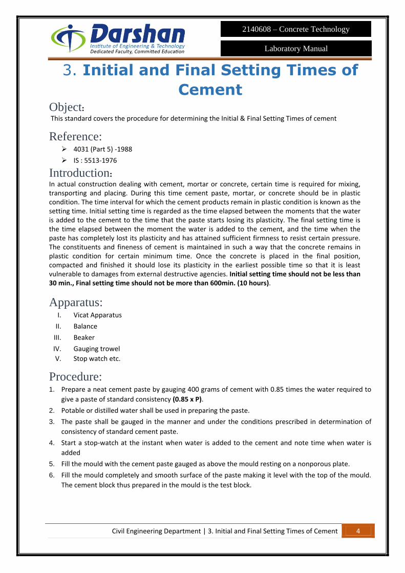
Procedure: 1. Prepare a neat cement paste by gauging 400 grams of cement with 0.85 times the water required to
give a paste of standard consistency (0.85 x P).
2. Potable or distilled water shall be used in preparing the paste.
3. The paste shall be gauged in the manner and under the conditions prescribed in determination of
consistency of standard cement paste.
4. Start a stop-watch at the instant when water is added to the cement and note time when water is
added
5. Fill the mould with the cement paste gauged as above the mould resting on a nonporous plate.
6. Fill the mould completely and smooth surface of the paste making it level with the top of the mould.
The cement block thus prepared in the mould is the test block.
Civil Engineering Department | 3. Initial and Final Setting Times of Cement 5
2140608 – Concrete Technology
Laboratory Manual
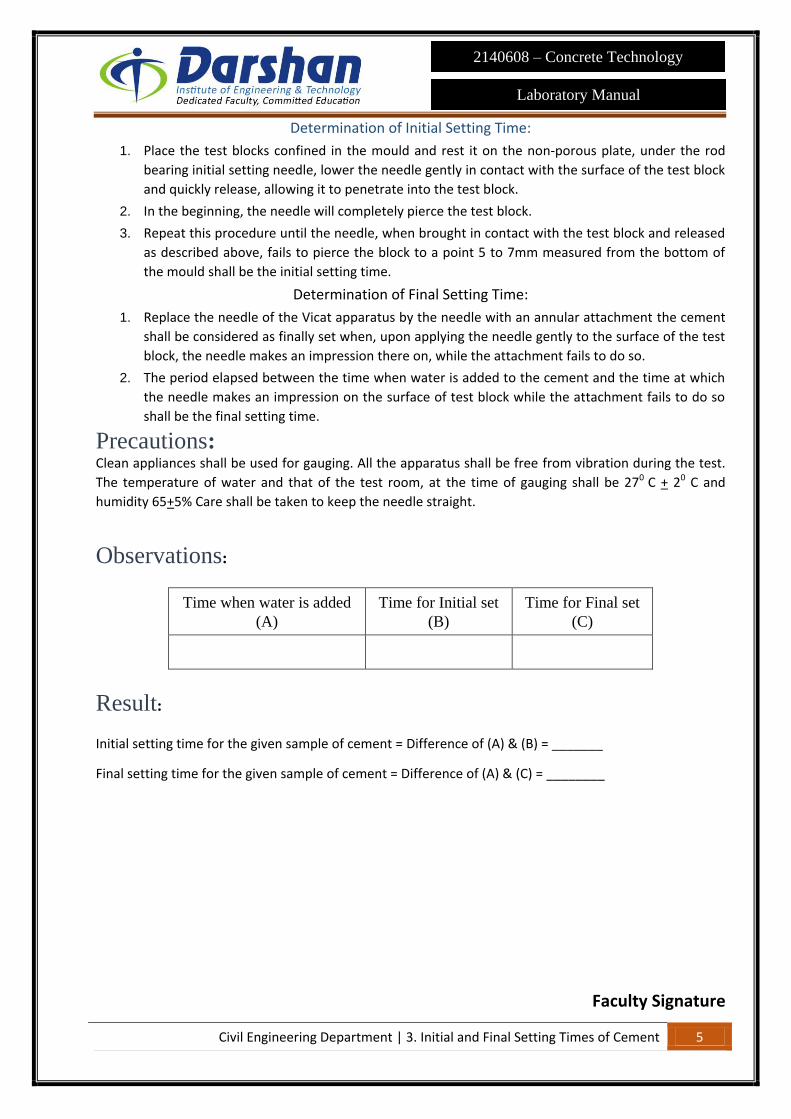
Determination of Initial Setting Time:
1. Place the test blocks confined in the mould and rest it on the non-porous plate, under the rod
bearing initial setting needle, lower the needle gently in contact with the surface of the test block
and quickly release, allowing it to penetrate into the test block.
2. In the beginning, the needle will completely pierce the test block.
3. Repeat this procedure until the needle, when brought in contact with the test block and released
as described above, fails to pierce the block to a point 5 to 7mm measured from the bottom of
the mould shall be the initial setting time.
Determination of Final Setting Time:
1. Replace the needle of the Vicat apparatus by the needle with an annular attachment the cement
shall be considered as finally set when, upon applying the needle gently to the surface of the test
block, the needle makes an impression there on, while the attachment fails to do so.
2. The period elapsed between the time when water is added to the cement and the time at which
the needle makes an impression on the surface of test block while the attachment fails to do so
shall be the final setting time.
Precautions: Clean appliances shall be used for gauging. All the apparatus shall be free from vibration during the test.
The temperature of water and that of the test room, at the time of gauging shall be 270 C + 20 C and
humidity 65+5% Care shall be taken to keep the needle straight.
Observations:
Time when water is added
(A)
Time for Initial set
(B)
Time for Final set
(C)
Result:
Initial setting time for the given sample of cement = Difference of (A) & (B) = _______
Final setting time for the given sample of cement = Difference of (A) & (C) = ________
Faculty Signature

Civil Engineering Department | 4. Soundness of Cement 6
2140608 – Concrete Technology
Laboratory Manual
4. Soundness of Cement Object: This standard covers the procedures for determining the soundness of cement.
Reference: IS: 4031 (Part 3) -1988
IS : 5514-1969
Introduction: It is essential that the cement concrete shall not undergo appreciable change in volume after setting. This
is ensured by limiting the quantities of free lime, magnesia and sulphats in cement which are the causes
of the change in volume known as unsoundness. Unsoundness in cement does not come to surface for a
considerable period of time. This test is designed to accelerate the slaking process by the application of
heat and discovering the defects in a short time. Unsoundness produces cracks, distortion and
disintegration there by giving passage to water and atmospheric gases which may have injurious effects
on concrete and reinforcement.
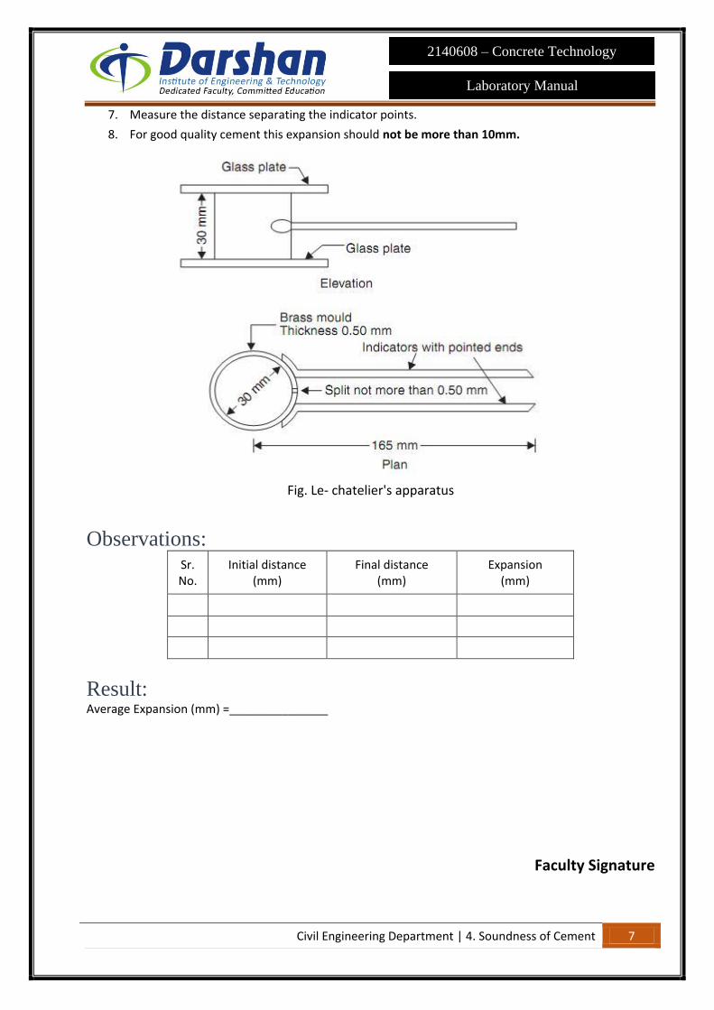
The apparatus for conducting the test consists of small split cylinder of spring brass or other suitable
metal of 0.5mm thickness forming a mould 30 mm internal diameter and 30mm height. On either side of
the split mould are attached to indicators with pointed ends, the distance from these ends to the center
of the cylinder being 165 mm.
Apparatus: I. Le-Chatelier apparatus
II. Balance
III. Water bath
IV. Beaker etc.
Procedure:
1. Place the lightly oiled mould on a lightly oiled glass sheet and fill it with cement paste formed by
gauging cement with 0.78 times the water required to give a paste of standard consistency.
2. The paste shall be gauged in the manner and under the conditions prescribed in determination of
consistency of standard cement paste, taking care to keep the edges of the mould gently
together.
3. Measure the distance separating the indicator points.
4. While this operation is being performed cover the mould with another piece of glass sheet, place
a small weight on this covering glass sheet and immediately submerge the whole assembly in
water at a temperature of 270+ 20C and keep there for 24 hours.
5. After then put mould in water bath Bring the water to boiling, with the mould kept submerged, in
25 to 30 minutes, and keep it boiling for three hours.
6. Remove the mould from the water allow it to cool and measure the distance between the
indicator points. The difference between these two measurements represents the expansion of
the cement.
Civil Engineering Department | 4. Soundness of Cement 7
2140608 – Concrete Technology
Laboratory Manual
7. Measure the distance separating the indicator points.
8. For good quality cement this expansion should not be more than 10mm.
Fig. Le- chatelier's apparatus
Observations: Sr. No.
Initial distance (mm)
Final distance (mm)
Expansion (mm)
Result: Average Expansion (mm) =_______________
Faculty Signature

Civil Engineering Department | 5. Compressive Strength of Cement 8
2140608 – Concrete Technology
Laboratory Manual
5. Compressive Strength of Cement Object: This method of test covers the procedures for determining the Strength of cement as represented by
compressive strength tests on mortar cubes compacted by means of a standard vibration machine.
Reference:
IS: 4031 (Part 6) -1988
IS : 10080-1982
IS : 650-1966
IS: 269-1976
Introduction: The compressive strength of cement mortars is determined in order to verify whether the cement
conforms to IS specifications and whether it will be able to develop the required compressive strength of
concrete. The average compressive strength of at least three mortar cubes (area of the face 50 cm2 )
composed of one part of cement and three parts of standard stand should satisfy IS code specifications.
Apparatus: I. Cubes having size of 7.06 X 7.06 X 7.06 cm
II. Balance
III. Baby vibrator
IV. Water bath
V. Gauging Trowel etc.
Procedure: 5. The Standard or Natural sand to be used in the test.
6. Take 600 grams of Standard or Natural sand, 200 grams of cement (i.e. ratio of cement to sand
is 1:3) in a non-porous enamel tray & mix them with a trowel for 1minute.
7. Add water of quantity (P/4) + 3 % (for Standard sand) or (P/4) + 3.5 % (for Natural sand) of
combined weight of cement & sand and mix the three ingredients thoroughly until the mixture
is of uniform colour. The time of mixing should not be less than 3 minutes and not more than 4
minutes.
8. Immediately after mixing, the mortar is filled into a cube mould.
9. The area of the face of the cube will be equal to 50cm2.
10. Compact the mortar either by hand compaction in a standard specified manner or on the
vibrating equipment (12000 RPM).
11. Keep the compacted cube in the mould at a temperature of 270+ 20C & at least 90% relative
humidity for 24hours.
12. Where the facility of standard temperature & humidity room is not available, the cube may be
kept under wet gunny bag to stimulate 90% relative humidity.
13. After 24hours, remove the cubes from the mould & immerse in clean fresh water until taken
out for curing.
14. Three cubes for each are tested for compressive strength at the interval of 3, 7 & 28 days.

Civil Engineering Department | 5. Compressive Strength of Cement 9
2140608 – Concrete Technology
Laboratory Manual
Testing:
1. Test three cubes for compressive strength at the periods mentioned under the relevant
specification for different hydraulic cements, the periods being reckoned from the completion
of vibration.
2. The compressive strength shall be the average of the strengths of three cubes for each period
of curing.
3. The cubes shall be tested on their sides without any packing between the cube and the steel
plates of the testing machine.
4. One of the plates shall be carried base and shall be self-adjusting and the load shall be
steadily and uniformly applied starting from zero at a rate of 350 Kgs/Cm2/ min.
5. The cubes are tested at the following period Ordinary portland cement 3, 7 and 28 days. Rapid
hardening portland cement 1 and 3 days. Low heat portland cement 3 and 7 days etc.
Precautions: Inside of the cube moulds should be oiled.
Materials: Cement (gm) Sand (gm) Water (ml)
Observation:
Sr. No.
Days
Dimension Area (mm2)
(A) Load taken (N)
(B)
Compressive Strength (B)/(A)
Average Compressive
Strength (N/mm2)
Length (mm)
Width (mm)
Result: The average compressive strength of the given cement,
At 3 days N/mm2 =
At 7 days N/mm2 =
At 28 days N/mm2 =
Faculty Signature
Civil Engineering Department | 6. Particle size distribution of FA 10
Laboratory Manual
2140608 – Concrete Technology
6. Particle size distribution of FA
Object: To determine fineness modulus of fine aggregate and classifications based on IS: 383-1970
Reference: IS: 2386 (Part 1) -1996
IS:460-1962
IS: 383-1970
Introduction: This is the name given to the operation of dividing a sample of aggregate into various fractions each consisting
of particles of the same size. The sieve analysis is conducted to determine the particle size distribution in a
sample of aggregate, which we call gradation. Many a time, fine aggregates are designated as fine sand,
medium sand and coarse sand. These classifications do not give any precise meaning. What the supplier terms
as fine sand may be really medium or even coarse sand.
The following limits may be taken as guidance:
Fine sand: F.M. : 2.2 - 2.6
Medium sand: F.M. : 2.6 - 2.9
Coarse sand: F.M. : 2.9 - 3.2
(Note: Sand having a fineness modulus more than 3.2 will be unsuitable for making satisfactory concrete.)
Test sample: The weight of the sample available shall not be less than the weight given in the table below. The sample for
sieving shall be prepared from the larger sample either by quartering or by means of sample divider.
Maximum Size present in Substantial proportions
(mm)
Minimum weight of sample required for
quartering (Kg)
20 25
10 6
6.3 3
Civil Engineering Department | 6. Particle size distribution of FA 11
Laboratory Manual
2140608 – Concrete Technology
Minimum weight of sample required for Sieve analysis after Quartering shall be as follows.
Maximum Size present in Substantial
proportions (mm)
Minimum weight of sample required for Sieve
analysis (Kg)
20 2.0
10 0.5
4.75 0.2
Apparatus: I. Sieves (Conforming to IS:460-1962) of size 40mm, 20mm, 12.5mm, 10mm, 4.75mm, 2.36mm,
1.18mm, 600 micron, 300 micron, 150 micron and pan.
II. Balance
III. Sieve Shaker
Procedure: 1. The sample shall be brought to an air-dry condition before weighing and sieving. The air-dry sample
shall be weighed and sieved successively on the appropriate sieves starting with the largest. Care
shall be taken to ensure that the sieves are clean before use.
2. The shaking shall be done with a varied motion, backward and forwards, left to right, circular
clockwise and anti-clockwise, and with frequent jarring, so that the material is kept moving over the
sieve surface in frequently changing directions.
3. Material shall not be forced through the sieve by hand pressure. Lumps of fine material, if present,
may be broken by gentle pressure with fingers against the side of the sieve.
4. Light brushing with a fine camel hair brush may be used on the 150-micron IS Sieves to prevent
aggregation of powder and blinding of apertures.
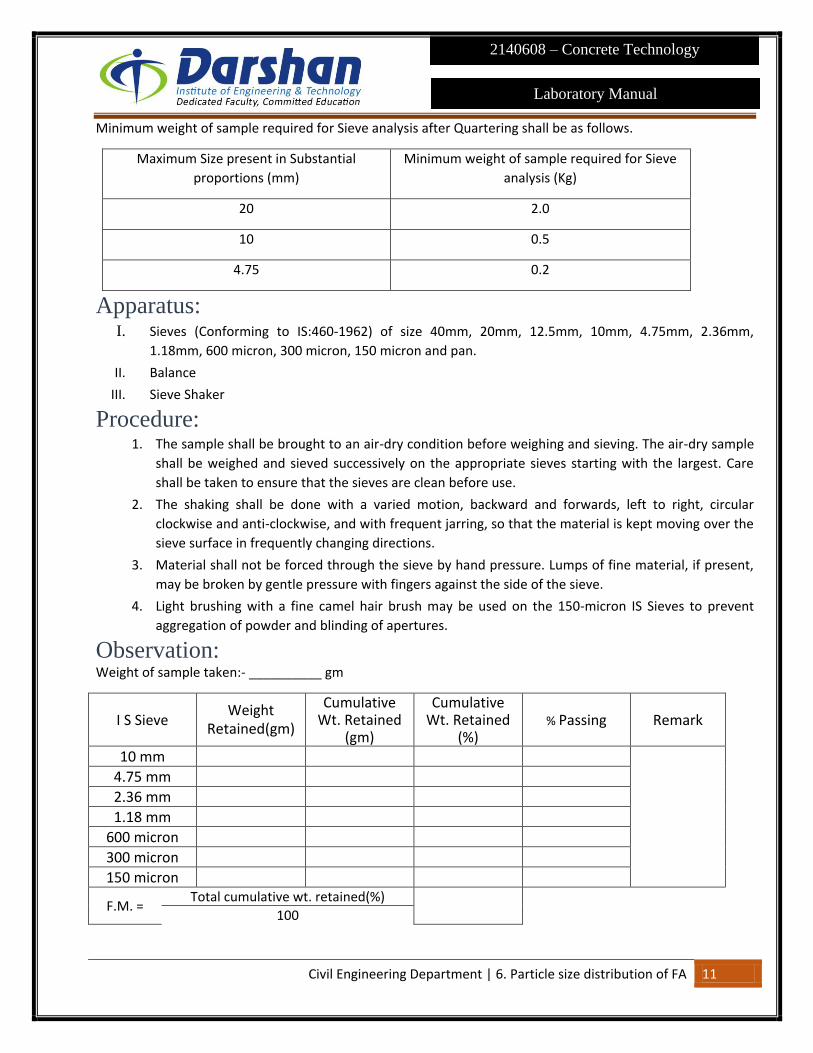
Observation: Weight of sample taken:- __________ gm
I S Sieve Weight
Retained(gm)
Cumulative Wt. Retained
(gm)
Cumulative Wt. Retained
(%)
% Passing Remark
10 mm
4.75 mm
2.36 mm
1.18 mm
600 micron
300 micron
150 micron
F.M. = Total cumulative wt. retained(%)
100

Civil Engineering Department | 6. Particle size distribution of FA 12
Laboratory Manual
2140608 – Concrete Technology
Reference: IS:383:1970 table no.4 grading limits of fine aggregates
Faculty Signature

Civil Engineering Department | 7. Specific Gravity, Moisture content and Water Absorption for Fine and Course Aggregate
13
Laboratory Manual
2140608 – Concrete Technology
7. Specific Gravity, Moisture content
and Water Absorption for Fine and
Course Aggregate Object: To determine specific gravity, moisture content and water absorption of a given sample of fine and
course aggregate.
Reference: IS : 2386 ( Part III ) – 1963
Apparatus: I. Balance of capacity not less than 3 kg with accuracy of 0.5 gm
II. Oven to maintain a temperature of 100 to 110oC
III. Pycnometer of about 1 L capacity
IV. Tray for drying the sample etc.
Procedure: 1. Keep the sample to be tested in water for 24 ± ½ hour and remove the entrapped air by gentle
agitation
2. After 24 hours drain the water and being the sample to saturated surface dry condition
3. Take about 0.5 kg of sample and note down the weight (A)
4. Place the aggregate in the Pycnometer and fill it with distilled water and entrapped air shall be
eliminated by gently rotating the Pycnometer.
5. The Pycnometer shall be topped with distilled water till the water in the hole is flat.
6. Note down the weight (B).
7. The contents in the Pycnometer shall be emptied and the samples transferred to a metal tray. Care
should be taken that there should not be any wastage of sample while transferring.
8. The contents in the Pycnometer shall be emptied and the samples transferred to a metal tray. Care
should be taken that there should not be any wastage of sample while transferring.
9. The Pycnometer shall now filled with distilled water as before fill the water in the hole is flat.
10. Note down the weight (C).
11. The sample kept in the tray should be kept in oven for 24 ± ½ hour at 110oC.
12. Take the sample from the oven and cool it to room temperature.
13. Note down the weight of aggregate (D).

Civil Engineering Department | 7. Specific Gravity, Moisture content and Water Absorption for Fine and Course Aggregate
14
Laboratory Manual
2140608 – Concrete Technology
Fig. pycnometer bottle Now calculate the Specific gravity and Water absorption from the formulae given below:
Type of aggregate
Wt. of Sample
(W0)
Wt. Of pycnometer + wt. of material +
wt. of water (A)
Wt. of pycnometer + wt.
of water (B)
Wt. of Saturated
Surface Dry Aggregate
(C)
Wt. of oven dry aggregate
(D)
FA
CA
Calculation: Test Value
Moisture Content=W0−D
𝐷
Water Absorption=C−D
𝐷x100
Specific gravity =D
C−(A−B)
Result:
I. The Moisture Content of a given sample of fine aggregate is found to be ……………%
II. The Water Absorption of a given sample of fine aggregate is found to be ……………%
III. The Specific Gravity of a given sample of fine aggregate is found to be …………..
IV. The Moisture Content of a given sample of Coarse aggregate is found to be ……………%
V. The Water Absorption of a given sample of Course aggregate is found to be ………….. %
VI. The Specific Gravity of a given sample of Course aggregate is found to be …………..
Faculty Signature

Civil Engineering Department | 8. Flakiness Index and Elongation Index 15
Laboratory Manual
2140608 – Concrete Technology
8. Flakiness Index and Elongation
Index Object: To determine the value of Flakiness Index and Elongation Index of Coarse aggregates.
Reference : IS: 2386 (Part 1) -1963]
IS: 383-1970
IS : 460-1962
Introduction: Particle shape and surface texture influence the properties of freshly mixed concrete more than the properties
of hardened concrete. Rough-textured, angular, and elongated particles require more water to produce
workable concrete than smooth, rounded compact aggregate. Consequently, the cement content must also be
increased to maintain the water-cement ratio. Generally, flat and elongated particles are avoided or are
limited to about 15 % by weight of the total aggregate.
Apparatus :
The metal gauge shall be of the pattern shown in Fig. 10.1, Balance, Gauging Trowel, Stop Watch,
etc.
Fig. Thickness gauge

Civil Engineering Department | 8. Flakiness Index and Elongation Index 16
Laboratory Manual
2140608 – Concrete Technology
Fig. Length Gauges
Procedure:
Flakiness Index 1) The sample shall be sieved through the sieves specified in Table
Dimension of Thickness and Length Gauges
(Clause 4.2, 4.4.1, 4.4.2, 5.2 and 5.4.1)
Size of Aggregate Thickness Gauge *
(mm)
Length Gauge ↑
(mm) Passing Through
IS Sieve
Retained on
IS Sieve
(1) (2) (3) (4)
63 mm 50 mm 33.90 --
50 mm 40 mm 27.00 81.0
40 mm 31.5 mm 21.5 64.4
31.5 mm 25 mm 16.95 --
25 mm 20 mm 13.50 40.5
20 mm 16 mm 10.80 32.4
16 mm 12.5 mm 8.55 25.6
12.5 mm 10 mm 6.75 20.2
10 mm 6.3 mm 4.89 14.7
* This dimension is equal to 0.6 times the mean sieve size
↑ This dimension is equal to 1.8 times the mean sieve size
1. At least 200 pieces shall be taken from each fraction and the flaky samples shall be weighed to an
accuracy of 0.1 % of the test sample
2. Calculate the flakiness index by
Wt. of flaky samples (passing) x 100
Wt. of total sample taken for test

Civil Engineering Department | 8. Flakiness Index and Elongation Index 17
Laboratory Manual
2140608 – Concrete Technology
Elongation Index Elongation Index of an aggregate is the percentage by weight of particles whose greatest dimension (length) is
greater than 1.8 times their mean dimension. At least 200 pieces shall be taken from each fraction and the
elongated samples shall be separated from the total sample taken.
Calculate the Elongation Index by
Wt. of elongated samples (passing) x 100
Wt. of total sample taken for test
Observation:
The flakiness index of a given sample of Course aggregate is …………………. %
The elongation index of a given sample of Course aggregate is ……………….. %
Faculty Signature

Civil Engineering Department | 9. Impact Value Test 18
Laboratory Manual
2140608 – Concrete Technology
9. Impact Value Test Object: This method of test covers the procedure for determining the aggregate impact value of coarse aggregate.
Reference: IS: 2386 (Part 4) -1963
IS: 383-1970
Introduction: The aggregate impact value gives a relative measure of the resistance of an aggregate to sudden shock or
impact, which in some aggregates differs from its resistance to a slow compressive load.
Apparatus:
An impact testing machine of the general form shown in Fig. 4 and complying with the following:
I. Total weight not more than 60kg nor less than 45kg.
II. The machine shall have a metal base weighing between 22 and 30 kg with a plane lower surface of
not less than 30 cm diameter, and shall be supported on a level and plane concrete or stone block or
floor at least 45 cm thick. The machine shall be prevented from rocking either by fixing it to the block
or floor or by supporting it on a level and plane metal plate cast into the surface of the block or floor.
III. A cylindrical steel cup of internal dimensions: Diameter 102 mm, Depth 50 mm and not less than 6.3
mm thick. A cylindrical metal measure, tared to the nearest, gram of sufficient rigidity to retain its
form under rough usage, and of 75mm diameter and 50mm depth.
IV. A metal cup or hammer weighing 13.5 to 14.0 kg, the lower end of which shall be cylindrical in shape,
100.0 mm in diameter and 5 cm long, with a 2 mm chamfer at the lower edge, and case-hardened.
The hammer shall slide freely between vertical guides so arranged that the lower (cylindrical) part of
the hammer is above and concentric with the cup.
V. Means for raising the hammer and allowing it to fall freely between the vertical guides from a height
of 380.0 mm on to the test sample in the cup, and means for adjusting the height of fall within 5 mm.
VI. Sieves-The IS Sieves of sizes 12.5, 10 and 2.36 mm, Tamping Rod 23 cm long and 1 cm in dia., balance
of capacity not less than 500 g, Oven etc.

Civil Engineering Department | 9. Impact Value Test 19
Laboratory Manual
2140608 – Concrete Technology
Fig. : Aggregate Impact Testing Machine
Procedure `:
1. The test sample shall consist of aggregate the whole of which passes a 12.5 mm IS Sieve and is
retained on a 10 mm IS Sieve. The aggregate comprising the test sample shall be dried in an oven for
a period of four hours at a temperature of 100 to 110°C and cooled.
2. The measure shall be filled about one-third full with the aggregate and tamped with 25 strokes of
the rounded end of the tamping rod. The net weight of aggregate in the measure shall be
determined the weight of sample in gram (Weight A).
3. The impact machine shall rest without wedging or packing upon the level plate, block or floor, so
that it is rigid and the hammer guide columns are vertical.
4. The cup shall be fixed firmly in position on the base of the machine and the whole of the test sample
placed in it and compacted by a single tamping of 25 strokes of the tamping rod.
5. The hammer shall be raised until its lower face is 380 mm above the upper surface of the aggregate
in the cup, and allowed to fall freely on to the aggregate. The test sample shall be subjected to a
total of 15 such blows each being delivered at an interval of not less than one second.
6. The crushed aggregate shall then be removed from the cup and the whole of it sieved on the 2.36
mm IS Sieve until no further significant amount passes in one minute. The fraction passing the sieve
shall be weighed to an accuracy of 0.1 g (Weight. B).
7. The fraction retained on the sieve shall also be weighed (Weight C) and, if the total weight (C+B) is
less than the initial weight (Weight A) by more than one gram, the result shall be discarded and a
fresh test made. Two tests shall be made.
Calculation:
The ratio of the weight of fines formed to the total sample weight in each test shall he expressed as a
percentage, the result being recorded to the first decimal place:
Aggregate Impact Value X 100

Civil Engineering Department | 9. Impact Value Test 20
Laboratory Manual
2140608 – Concrete Technology
A weight in gm of saturated surface - dry sample=______gm
B weight in gm of fraction passing through 2.36 mm IS Sieve=_______gm
C=Weight in gm of fraction retained on 2.36 mm IS Sieve=______gm
D=Difference due to loss of Material=A-(B+C)=______gm (Should be <1gm)
Result:
The aggregate Impact value of given sample of coarse aggregate is ……….. %
The aggregate impact value should not be more than 45 per cent for aggregate used for concrete other than
for wearing surfaces, and 30 per cent for concrete used for wearing surfaces such a runways, roads and air
field pavements.
Faculty Signature

Civil Engineering Department | 10. Determination of Aggregate Crushing value 21
Laboratory Manual
2140608 – Concrete Technology
10. Determination of Aggregate
Crushing value Objective: This method of test covers the procedure for determining the aggregate crushing value of coarse aggregate.
Reference: IS : 2386 ( Part IV) – 1963
IS: 383-1970
Apparatus: A 15-cm diameter open-ended steel cylinder, with plunger and base-plate, of the general form and dimensions
shown in Fig. ,A straight metal tamping rod, A balance of capacity 3 kg, readable and accurate to one gram, IS
Sieves of sizes 12.5, 10 and 2.36 mm, For measuring the sample, cylindrical metal measure of sufficient rigidity
to retain its form under rough usage and of the following internal dimensions: Diameter 11.5 cm and Height
18.0 cm
Fig.: Aggregate crushing value apparatus
Civil Engineering Department | 22
Laboratory Manual
2140608 – Concrete Technology
Procedure:
1. The material for the standard test shall consist of aggregate passing a 12.5 mm IS Sieve and retained
on a 10 mm IS Sieve, and shall be thoroughly separated on these sieves before testing.
2. The aggregate shall be tested in a surface-dry condition. If dried by heating, the period of drying
shall not exceed four hours, the temperature shall be 100 to 110°C and the aggregate shall be
cooled to 33 room temperature before testing.
3. The appropriate quantity may be found conveniently by filling the cylindrical measure in three
layers of approximately equal depth, each layer being tamped 25 times with the rounded end of the
tamping rod and finally leveled off, using the tamping rod as a straight-edge.
4. The weight of material comprising the test sample shall be determined (Weight A) and the same
weight of sample shall be taken for the repeat test.
5. The apparatus, with the test sample and plunger in position, shall then be placed between the
platens of the testing machine and loaded at as uniform a rate as possible so that the total load is
reached in 10 minutes. The total load shall be 400 kN.
6. The load shall be released and the whole of the material removed from the cylinder and sieved on a
2.36 mm IS Sieve for the standard test. The fraction passing the sieve shall be weighed (Weight B).
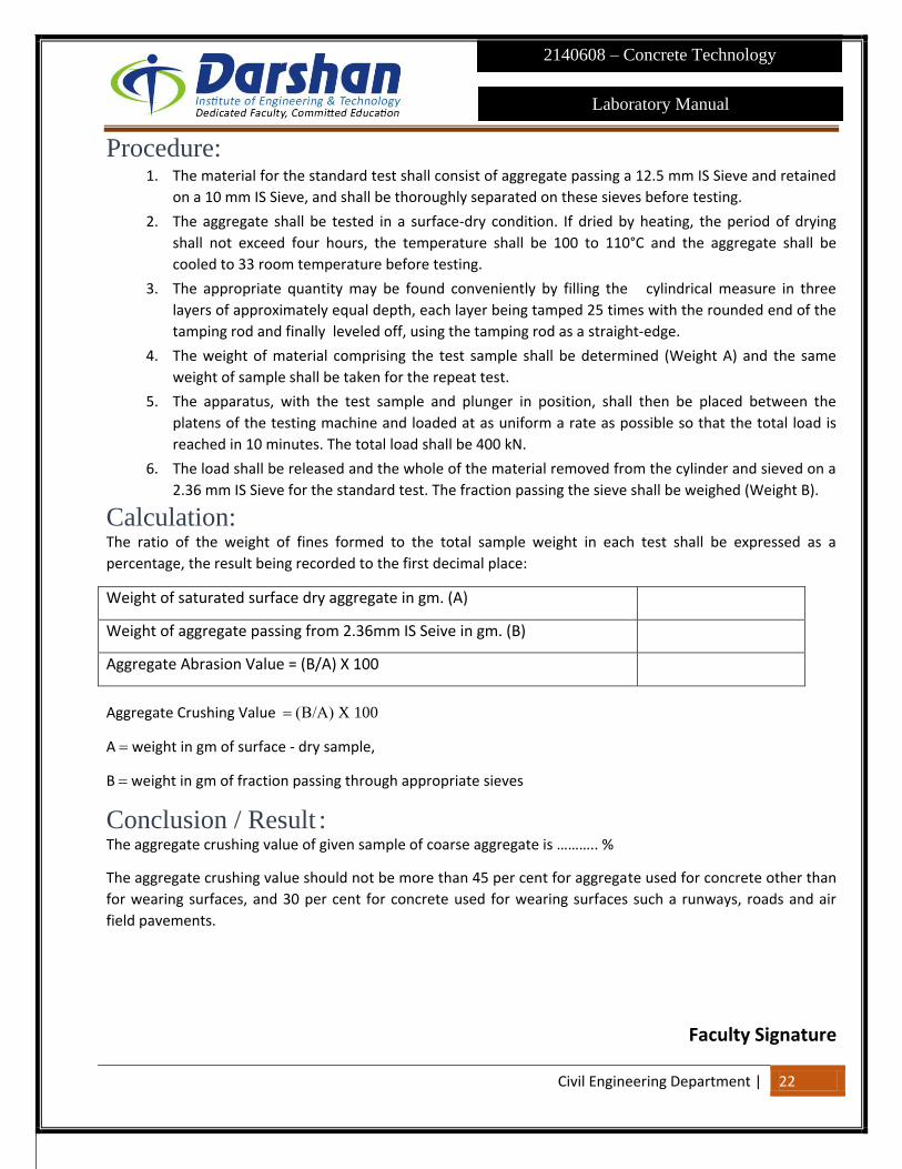
Calculation:
The ratio of the weight of fines formed to the total sample weight in each test shall be expressed as a
percentage, the result being recorded to the first decimal place:
Weight of saturated surface dry aggregate in gm. (A)
Weight of aggregate passing from 2.36mm IS Seive in gm. (B)
Aggregate Abrasion Value = (B/A) X 100
Aggregate Crushing Value X 100
A weight in gm of surface - dry sample,
B weight in gm of fraction passing through appropriate sieves
Conclusion / Result :
The aggregate crushing value of given sample of coarse aggregate is ……….. %
The aggregate crushing value should not be more than 45 per cent for aggregate used for concrete other than
for wearing surfaces, and 30 per cent for concrete used for wearing surfaces such a runways, roads and air
field pavements.
Faculty Signature

Civil Engineering Department | 11. Aggregate Abrasion Value 23
Laboratory Manual
2140608 – Concrete Technology
11. Aggregate Abrasion Value
Object: This method of test methods of determining the abrasion value of coarse aggregate by the use of Los Angeles
machine.
Reference: IS: 2386 (Part 4) -1996]
IS: 383-1970
Introduction:
Abrasive Charge-The abrasive charge shall consist of cast iron spheres or steel spheres approximately 48 mm
in. diameter and each weight between 390 and 445 g.
Table: Specified abrasive charge The test sample consist of clean aggregate which has been dried in an oven at 105°C to 110°C and it should
conform to one of the grading shown in Table.
Table: Grading of test samples

Civil Engineering Department | 11. Aggregate Abrasion Value 24
Laboratory Manual
2140608 – Concrete Technology
Apparatus: Los Angeles machine - The Los Angeles abrasion testing machine shall consist of a hollow steel cylinder, closed
at both ends, having an inside diameter of 700 mm and an inside length of 500 mm. The cylinder shall be
mounted on stub shafts attached to the ends of the cylinders but not entering it, and shall be mounted in
such, a manner that it may be rotated about its axis in a horizontal position. An opening in the 37 cylinder shall
be provided for the introduction of the test sample. A removable steel shelf, projecting radially 88 mm into
the cylinder and extending its full length, shall be mounted along one element of the interior surface of the
cylinder. The shelf shall be of such thickness and so mounted, by bolts or other approved means, as to be firm
and rigid. The 1.70 mm IS Sieve.
Fig.: Loss Angeles Abrasion Testing Machine
Procedure:
1. The test sample shall consist of clean aggregate which has been dried in an oven at 105 to 110°C to
substantially constant weight and shall conform to one of the grading shown in Table 3.22. The
grading used shall be those most nearly representing the aggregate furnished for the work.
2. The test sample and the abrasive charge shall be placed in the Los Angeles abrasion testing machine
and the machine rotated at a speed of 20 to 33 rev/min. For grading A, B, C and D, the machine shall
be rotated for 500 revolutions; for grading E, F and G, it shall be rotated for 1 000 revolutions.
3. The machine shall be so driven and so counter-balanced as to maintain a substantially uniform
peripheral speed. If an angle is used as the shelf, the machine shall be rotated in such a direction
that the charge is caught on the outside surface of the angle.
4. At the completion of the test, the material shall be discharged from the machine and a preliminary
separation of the sample made on a sieve coarser than the 1.70 mm IS Sieve.
5. The material coarser than the 1.70 mm IS Sieve shall be washed dried in an oven at 105 to 110°C to
a substantially constant weight, and accurately weighed to the nearest gram.
Calculation :
The difference between the original weight and the final weight of the test sample is expressed as a
percentage of the original weight of the test sample. This value is reported as the percentage of wear.

Civil Engineering Department | 11. Aggregate Abrasion Value 25
Laboratory Manual
2140608 – Concrete Technology
Description Sample 1 Sample 2
Weight of aggregate in gm. (A)
Weight of aggregate passing from 1.70mm IS Sieve in gm. (B)
Aggregate Abrassion Value in % = (B/A) X 100
Result: The aggregate Abrasion Value of given sample of coarse aggregate is ……….. %
Faculty Signature

Civil Engineering Department | 12. Slump Test 26
Laboratory Manual
2140608 – Concrete Technology
12. Slump Test
Object: To determine the workability or consistency of concrete mix of given proportion by slump test.
Apparatus: Iron pan to mix concrete
Weighing machine
Trowel
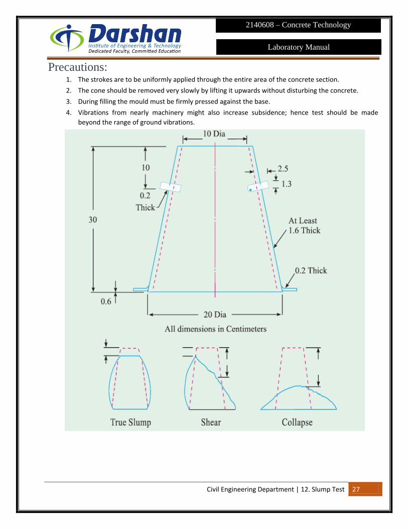
Slump cone
Scale and tamping rod etc.
Procedure: Unsupported concrete, when it is fresh, will flow to the sides and a sinking in height will take place. This
vertical settlement is called slump. Slump is a measure for W/C ratio 0.5, 0.6 and 0.7 for each mix take 10 Kg.
C.A., 5 Kg. FA and 2.5 Kg. Cement.
1. Mix the dry constituents thoroughly to get a uniform colour and then add water.
2. The internal surface of the mould is to be thoroughly cleaned and placed on a smooth, horizontal,
rigid and non absorbent surface.
3. Place the mixed concrete in the cleaned slump cone in 3 layers each approximately 1/3 in height of
the mould. Tamp each layer 25 times with tamping rod.
4. Remove the cone immediately, rising it slowly and carefully in the vertical direction.
5. As soon as the concrete settlement comes to a stop, measure the subsistence of the concrete in
cms, which gives the slump.
Note: Slump test is adopted in the Laboratory or during the progress of the work in the field for determining
consistency of concrete where nominal max., size of aggregates does not exceed 40 mm. Any slump specimen
which collapses or shears off laterally gives incorrect results and at this juncture the test is repeated only true
slump should be measured.
Observations: SR NO w/c ratio Slump in mm
1 0.5
2 0.6
3 0.7
Civil Engineering Department | 12. Slump Test 27
Laboratory Manual
2140608 – Concrete Technology
Precautions: 1. The strokes are to be uniformly applied through the entire area of the concrete section.
2. The cone should be removed very slowly by lifting it upwards without disturbing the concrete.
3. During filling the mould must be firmly pressed against the base.
4. Vibrations from nearly machinery might also increase subsidence; hence test should be made
beyond the range of ground vibrations.
Civil Engineering Department | 12. Slump Test 28
Laboratory Manual
2140608 – Concrete Technology
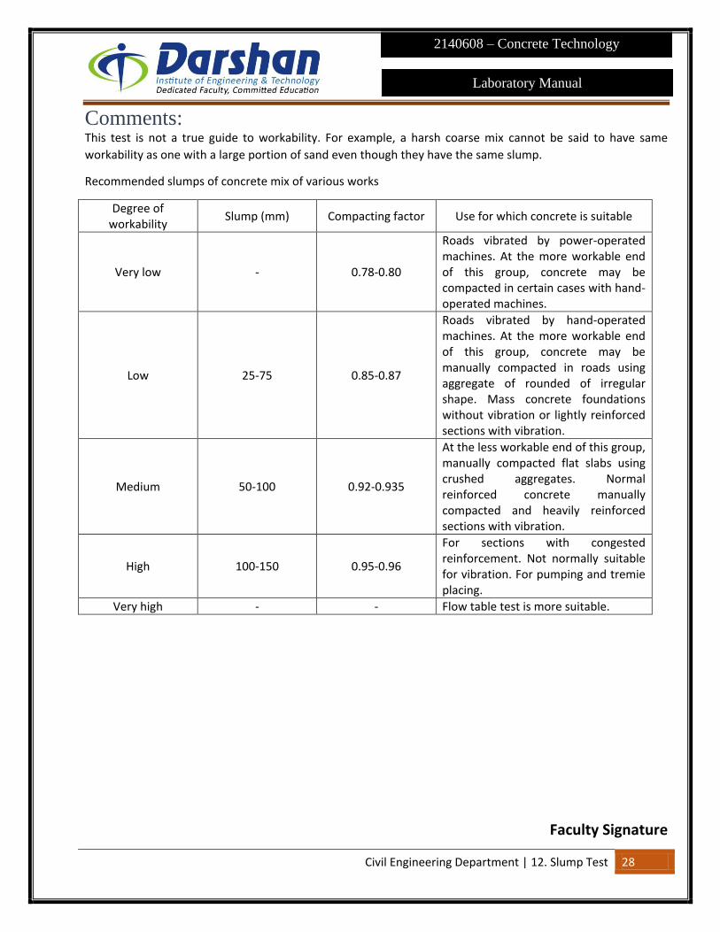
Comments: This test is not a true guide to workability. For example, a harsh coarse mix cannot be said to have same
workability as one with a large portion of sand even though they have the same slump.
Recommended slumps of concrete mix of various works
Degree of workability
Slump (mm) Compacting factor Use for which concrete is suitable
Very low - 0.78-0.80
Roads vibrated by power-operated machines. At the more workable end of this group, concrete may be compacted in certain cases with hand-operated machines.
Low 25-75 0.85-0.87
Roads vibrated by hand-operated machines. At the more workable end of this group, concrete may be manually compacted in roads using aggregate of rounded of irregular shape. Mass concrete foundations without vibration or lightly reinforced sections with vibration.
Medium 50-100 0.92-0.935
At the less workable end of this group, manually compacted flat slabs using crushed aggregates. Normal reinforced concrete manually compacted and heavily reinforced sections with vibration.
High 100-150 0.95-0.96
For sections with congested reinforcement. Not normally suitable for vibration. For pumping and tremie placing.
Very high - - Flow table test is more suitable.
Faculty Signature

Civil Engineering Department | 13. Compacting Factor Test 29
Laboratory Manual
2140608 – Concrete Technology
13. Compacting Factor Test Object: To determine the workability of concrete mix of given proportion by compaction factor test.
Apparatus: Compaction factor apparatus
Trowel
Weighing machine
Compacting factor test apparatus etc.
Introduction: This test is adopted to determine workability of concrete where nominal size of aggregate does not exceed 40
mm. It is based on the definition, that workability is that property of concrete, which determines the amount
of work required to produce full compaction.
The test consists essentially of applying a standard amount of work to standard quantity of concrete and
measuring the resulting compaction.
The compaction factor is defined as the ratio of the weight of partially compacted concrete to the weight of
fully compacted concrete. It shall be stated to the nearest second decimal place.
Procedure: Conduct test for W/c ratio 0.5, 0.6, and 0.7, for each mix take 10 kg of coarse aggregate 5kg of fine aggregate
and 2.5 Kg of cement.
1. Grease the inner surface of the hoppers and the cylinder.
2. Fasten the hopper doors.
3. Weigh the empty cylinder accurately (Wt. Kgs).
4. Fix the cylinder on the base with fly nuts and bolts
5. Mix coarse and fine aggregates and cement dry until the mixture is uniform in colour and then with
water until concrete appears to be homogeneous.
6. Fill the freshly mixed concrete in upper hopper gently with trowel without compacting.
7. Release the trap door of the upper hopper and allow the concrete of fall into the lower hopper
bringing the concrete into standard compaction.
8. Immediately after the concrete comes to rest, open the trap door of the lower hopper and allow the
concrete to fall into the cylinder, bringing the concrete into standard compaction.
9. Remove the excess concrete above the top of the cylinder by a trowel.
10. Find the weight of cylinder i.e cylinder filled with partially compacted concrete (W2 kgs)

Civil Engineering Department | 13. Compacting Factor Test 30
Laboratory Manual
2140608 – Concrete Technology
11. Refill the cylinder with same sample of concrete in approx. 4 layers, tamping each layer with
tamping for 25 times in order to obtain full compaction of concrete.
12. Level the mix and weigh the cylinder filled with fully compacted concrete (W3 Kg)
13. Repeat the procedure for different for different a trowel.
Observations and Calculations: Weight of cylinder = W1 Kgs.
SR.NO. W/c ratio
Wt. With
partially
compaction
W2(Kgs)
Wt. With
fully
compaction
W3(Kgs)
Wt. With
partially
compacted
concrete(W2-
W3) (Kgs)
Wt. With fully
compacted
concrete(W3-
W1) (Kgs)
Compaction
factor (W1-
W2)/ (W3-
W1)
1 0.5
2 0.6
3 0.7
Civil Engineering Department | 13. Compacting Factor Test 31
Laboratory Manual
2140608 – Concrete Technology
Precautions: 1. The top hopper must be filled gently.
2. The mix should not be pressed or compacted in the hopper.
3. If the concrete in the hopper does not fall through when the trap door is released, it should be freed
by passing a metal rod. A single steady penetration will usually affect release.
Comments: It is more sensitive, precise than slump test and is particularly useful to concrete mixes of low workability.
Suggested ranges of values of compaction factors for different placing conditions have been shown in the
table show in slump test experiment.
Faculty Signature

Civil Engineering Department | 14. Compressive Strength Test 32
Laboratory Manual
2140608 – Concrete Technology
14. Compressive Strength Test Object: The test method covers determination of compressive strength of cubic concrete specimens. It consists of
applying a compressive axial load to molded cubes at a rate which is within a prescribed range until failure
occurs.
Reference: IS : 516 – 1959
IS: 1199-1959
SP : 23-1982
IS : 10086-1982
Introduction: Age at Test - Tests shall be made at recognized ages of the test specimens, the most usual being 7 and 28
days. Where it may be necessary to obtain the early strengths, tests may be made at the ages of 24 hours ± ½
hour and 72 hours ± 2 hours. The ages shall be calculated from the time of the addition of water to the dry
ingredients.
Number of Specimens - At least three specimens, preferably from different batches, shall be made for testing
at each selected age.
Apparatus: I. Compression Testing Machine
II. Cube Moulds - The mould shall be of 150 mm size conforming to IS: 10086-1982.
III. Weights and weighing device, Tools and containers for mixing, Tamping rod etc.
Procedure: 1. Sampling of Materials - Samples of aggregates for each batch of concrete shall be of the desired
grading and shall be in an air-dried condition. The cement samples, on arrival at the laboratory, shall
be thoroughly mixed dry either by hand or in a suitable mixer in such a manner as to ensure the
greatest possible blending and uniformity in the material.
2. Proportioning - The proportions of the materials, including water, in concrete mixes used for
determining the suitability of the materials available, shall be similar in all respects to those to be
employed in the work.
3. Weighing - The quantities of cement, each size of aggregate, and water for each batch shall be
determined by weight, to an accuracy of 0.1 percent of the total weight of the batch.
4. Mixing Concrete - The concrete shall be mixed by hand, or preferably, in a laboratory batch mixer, in
such a manner as to avoid loss of water or other materials. Each batch of concrete shall be of such a
size as to leave about 10 percent excess after moulding the desired number of test specimens.

Civil Engineering Department | 14. Compressive Strength Test 33
Laboratory Manual
2140608 – Concrete Technology
5. Mould - Test specimens cubical in shape shall be 15 × 15 × 15 cm. If the largest nominal size of the
aggregate does not exceed 2 cm, 10 cm cubes may be used as an alternative. Cylindrical test
specimens shall have a length equal to twice the diameter.
6. Compacting - The test specimens shall be made as soon as practicable after mixing, and in such a
way as to produce full compaction of the concrete with neither segregation nor excessive laitance.
7. Curing - The test specimens shall be stored in a place, free from vibration, in moist air of at least 90
percent relative humidity and at a temperature of 27° ± 2°C for 24 hours ± ½ hour from the time of
addition of water to the dry ingredients.
8. Placing the Specimen in the Testing Machine - The bearing surfaces of the testing machine shall be
wiped clean and any loose sand or other material removed from the surfaces of the specimen which
are to be in contact with the compression platens.
9. In the case of cubes, the specimen shall be placed in the machine in such a manner that the load
shall be applied to opposite sides of the cubes as cast, that is, not to the top and bottom.
10. The axis of the specimen shall be carefully aligned with the centre of thrust of the spherically seated
platen. No packing shall be used between the faces of the test specimen and the steel platen of the
testing machine.
11. The load shall be applied without shock and increased continuously at a rate of approximately 140
kg/sq cm/min until the resistance of the specimen to the increasing load breaks down and no
greater load can be sustained.
12. The maximum load applied to the specimen shall then be recorded and the appearance of the
concrete and any unusual features in the type of failure shall be noted.
Observation: Age of cube Wt. of cube
(Kg) Load (P) (N)
c/s area (A)
(mm2)
Compressive strength (N/mm2)
(P/A)
Average compressive
strength (N/mm2)
Result: I. The average ____Days Compressive Strength of concrete sample is found to be ______N/mm2.
II. The average ____ Days Compressive Strength of concrete sample is found to be _______ N/mm2.
Faculty Signature

Civil Engineering Department | 15. Tensile strength test or Split cylinder test 34
Laboratory Manual
2140608 – Concrete Technology
15. Tensile strength test or Split
cylinder test Object: This method covers the determination of the splitting tensile strength of cylindrical concrete specimens.
Reference: IS: 516 – 1959
IS: 1199-1959
SP: 23-1982
IS: 10086-1982
Introduction: Age at Test - Tests shall be made at recognized ages of the test specimens, the most usual being 7 and 28
days. Where it may be necessary to obtain the early strengths, tests may be made at the ages of 24 hours ±1/2
hour and 72 hours ± 2 hours. The ages shall be calculated from the time of the addition of water to the dry
ingredients.
Number of Specimens - At least three specimens, preferably from different batches, shall be made for testing
at each selected age.
Apparatus: I. Compression Testing Machine
II. Cylinders -The cylindrical mould shall be of 150 mm diameter and 300 mm height conforming to
IS:10086-1982.
III. Weights and weighing device
IV. Tools and containers for mixing
V. Tamping rod etc.
Procedure: 1. Sampling of Materials - Samples of aggregates for each batch of concrete shall be of the desired
grading and shall be in an air-dried condition. The cement samples, on arrival at the laboratory, shall
be thoroughly mixed dry either by hand or in a suitable mixer in such a manner as to ensure the
greatest possible blending and uniformity in the material.
2. Proportioning - The proportions of the materials, including water, in concrete mixes used for
determining the suitability of the materials available, shall be similar in all respects to those to be
employed in the work.
3. Weighing - The quantities of cement, each size of aggregate, and water for each batch shall be
determined by weight, to an accuracy of 0.1 percent of the total weight of the batch.

Civil Engineering Department | 15. Tensile strength test or Split cylinder test 35
Laboratory Manual
2140608 – Concrete Technology
4. Mixing Concrete - The concrete shall be mixed by hand, or preferably, in a laboratory batch mixer, in
such a manner as to avoid loss of water or other materials. Each batch of concrete shall be of such a
size as to leave about 10 percent excess after moulding the desired number of test specimens.
5. Mould - The cylindrical mould shall be of 150 mm diameter and 300 mm height conforming to IS:
10086-1982.
6. Compacting - The test specimens shall be made as soon as practicable after mixing, and in such a
way as to produce full compaction of the concrete with neither segregation nor excessive laitance.
7. Curing - The test specimens shall be stored in a place, free from vibration, in moist air of at least 90
percent relative humidity and at a temperature of 27° ± 2°C for 24 hours ± ½ hour from the time of
addition of water to the dry ingredients.
8. Placing the Specimen in the Testing Machine - The bearing surfaces of the supporting and loading
rollers shall be wiped clean, and any loose sand or other material removed from the surfaces of the
specimen where they are to make contact with the rollers.
9. Two bearings strips of nominal (1/8 in i.e 3.175mm) thick plywood, free of imperfections,
approximately (25mm) wide, and of length equal to or slightly longer than that of the specimen
should be provided for each specimen.
10. The bearing strips are placed between the specimen and both upper and lower bearing blocks of the
testing machine or between the specimen and the supplemental bars or plates.
11. Draw diametric lines an each end of the specimen using a suitable device that will ensure that they
are in the same axial plane. Center one of the plywood strips along the center of the lower bearing
block.
12. Place the specimen on the plywood strip and align so that the lines marked on the ends of the
specimen are vertical and centered over the plywood strip.
13. Place a second plywood strip lengthwise on the cylinder, centered on the lines marked on the ends
of the cylinder.
14. Apply the load continuously and without shock, at a constant rate within, the range of 689 to 1380
kPa/min splitting tensile stress until failure of the specimen
15. Record the maximum applied load indicated by the testing machine at failure. Note the type of
failure and appearance of fracture.
Observation: Age of
cylinder Wt. of
cylinder (Kg)
Load (N)-P Length (mm)
Diameter (mm)
Tensile strength (N/mm2)
[2P/ πLD]
Average tensile
strength (N/mm2)
Result: I. The average ____Days Tensile Strength of concrete sample is found to be ______N/mm2.
Faculty Signature

Civil Engineering Department | 16. Flexural Strength test 36
Laboratory Manual
2140608 – Concrete Technology
16. Flexural Strength test Object: This clause deals with the procedure for determining the flexural strength of moulded concrete flexure test
specimens
Reference: IS : 516 – 1959
IS: 1199-1959
SP : 23-1982
IS : 10086-1982
Introduction: Age at Test - Tests shall be made at recognized ages of the test specimens, the most usual being 7 and 28
days. Where it may be necessary to obtain the early strengths, tests may be made at the ages of 24 hours ±½
hour and 72 hours ± 2 hours. The ages shall be calculated from the time of the addition of water to the dry
ingredients.
Number of Specimens - At least three specimens, preferably from different batches, shall be made for testing
at each selected age.
Apparatus: I. Testing Machine - The testing machine may be of any reliable type, of sufficient capacity for the tests
and capable of applying the load at the rate specified in 5.5. The permissible error shall be not
greater than ± 2 percent of the maximum load.
II. Beam Moulds - The beam moulds shall conform to IS: 10086-1982. The standard size shall be 15 × 15
× 70 cm. Alternatively, if the largest nominal size of the aggregate does not exceed 19 mm,
specimens 10 × 10 × 50 cm may be used.
III. Weights and weighing device, Tools and containers for mixing, Tamper (square in cross section) etc.
Procedure: 1. Sampling of Materials - Samples of aggregates for each batch of concrete shall be of the desired
grading and shall be in an air-dried condition. The cement samples, on arrival at the laboratory, shall
be thoroughly mixed dry either by hand or in a suitable mixer in such a manner as to ensure the
greatest possible blending and uniformity in the material.
2. Proportioning - The proportions of the materials, including water, in concrete mixes used for
determining the suitability of the materials available, shall be similar in all respects to those to be
employed in the work.
3. Weighing - The quantities of cement, each size of aggregate, and water for each batch shall be
determined by weight, to an accuracy of 0.1 percent of the total weight of the batch.
Civil Engineering Department | 16. Flexural Strength test 37
Laboratory Manual
2140608 – Concrete Technology
4. Mixing Concrete - The concrete shall be mixed by hand, or preferably, in a laboratory batch mixer, in
such a manner as to avoid loss of water or other materials. Each batch of concrete shall be of such a
size as to leave about 10 percent excess after moulding the desired number of test specimens.
5. Mould - The standard size shall be 15 × 15 × 70 cm. Alternatively, if the largest nominal size of the
aggregate does not exceed 19 mm, specimens 10 × 10 × 50 cm may be used.
6. Compacting - The test specimens shall be made as soon as practicable after mixing, and in such a
way as to produce full compaction of the concrete with neither segregation nor excessive laitance.
7. Curing - The test specimens shall be stored in a place, free from vibration, in moist air of at least 90
percent relative humidity and at a temperature of 27° ± 2°C for 24 hours ± ½ hour from the time of
addition of water to the dry ingredients.
8. Placing the Specimen in the Testing Machine - The bearing surfaces of the supporting and loading
rollers shall be wiped clean, and any loose sand or other material removed from the surfaces of the
specimen where they are to make contact with the rollers.
9. The specimen shall then be placed in the machine in such a manner that the load shall be applied to
the uppermost surface as cast in the mould, along two lines spaced 20.0 or 13.3 cm apart.
10. The axis of the specimen shall be carefully aligned with the axis of the loading device. No packing
shall be used between the bearing surfaces of the specimen and the rollers.
11. The load shall be applied without shock and increasing continuously at a rate such that the extreme
fibre stress increases at approximately 7 kg/sq cm/min, that is, at a rate of loading of 400 kg/min for
the 15.0 cm specimens and at a rate of 180 kg/min for the 10.0 cm specimens.
12. The load shall be increased until the specimen fails, and the maximum load applied to the specimen
during the test shall be recorded. The appearance of the fractured faces of concrete and any
unusual features in the type of failure shall be noted.
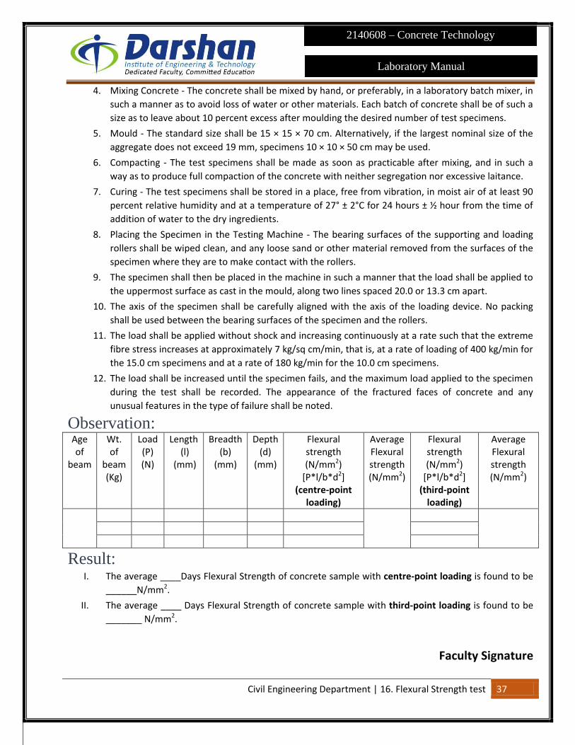
Observation: Age of
beam
Wt. of
beam (Kg)
Load (P) (N)
Length (l)
(mm)
Breadth (b)
(mm)
Depth (d)
(mm)
Flexural strength (N/mm2)
[P*l/b*d2] (centre-point
loading)
Average Flexural strength (N/mm2)
Flexural strength (N/mm2)
[P*l/b*d2] (third-point
loading)
Average Flexural strength (N/mm2)
Result: I. The average ____Days Flexural Strength of concrete sample with centre-point loading is found to be
______N/mm2.
II. The average ____ Days Flexural Strength of concrete sample with third-point loading is found to be
_______ N/mm2.
Faculty Signature