Danfoss Harmonic Calculation Software 2.0 Handbook … · Handbook Basic Level Danfoss Harmonic...
18
www.danfoss.de/vlt Handbook Basic Level Danfoss Harmonic Calculation Software 2.0
Transcript of Danfoss Harmonic Calculation Software 2.0 Handbook … · Handbook Basic Level Danfoss Harmonic...

www.danfoss.de/vlt
Handbook Basic LevelDanfoss Harmonic Calculation Software 2.0

Handbook - Danfoss HCS-Software V 2.0
© 2012 by Danfoss GmbH Seite 1
Handbook
Basic Level
Danfoss HCS Software 2.0
Date of last change: 14.08.2012

Handbook - Danfoss HCS-Software V 2.0
© 2012 by Danfoss GmbH Seite 2
Content 1. Introduction ....................................................................................................................................... 3
2. Selection of circuit ............................................................................................................................. 5
3. Data for Mains ................................................................................................................................... 6
4. Input data for FC1 (frequency converter) ........................................................................................... 8
5. Selection of FC1 from a list ............................................................................................................. 10
6. Overview / Start calculation ............................................................................................................. 11
7. Results ............................................................................................................................................ 12
8. Protocol ........................................................................................................................................... 13

Handbook - Danfoss HCS-Software V 2.0
© 2012 by Danfoss GmbH Seite 3
1. Introduction
[Picture 1b: Starting page]
The harmonic calculation software HCS is capable to compute the line distortion (harmonics up to
2,5kHz) caused by converters and to check the compliance to limits of norms. For this purpose one has
to supply datas of mains and converter to the software. Alternatively it is possible to compute the
harmonics of the mains of a generator. The distortion of the mains's voltage through circuit feedback is
caused by a current demand of no sinusoidal shape due to power electronic.
The programm is based on an extensive scientific simulation software, that was build up in cooperation
with the university of applied sciences RheinMain. The software is available for the user through login on
the webpage of danfoss's HCS. The handling of the software is alike the well-known windows surface,
composed graphically and easy to understand. The previously given values are meant as hint for the
expected magnitude and can be overwritten. Started with the initially given values, the programm
considers a mains with average workload.
The results are not based on tables of benchmarks, but on real computations of interactions between
workload and impedance of the mains. Correctly reproduced is for example the extinction of harmonics
due to single phase devices of office and household (PC, TV, …) by three phase frequency converters.
Furthermore capacitors are not simply considered as compensations of reactive current with 50 Hz sine-
current, but there are computed the harmonic currents considering resonances with impedance of
transformer and power cables. The results are presented as tables, bar charts and as u(t)- and i(t)-
diagramms, and on exceedance of the norms limits, there is given a warning hint.
Click on „Start“. Try the HCS on: http://www.danfoss-hcs.com/.
Handbook - Danfoss HCS-Software V 2.0
© 2012 by Danfoss GmbH Seite 4
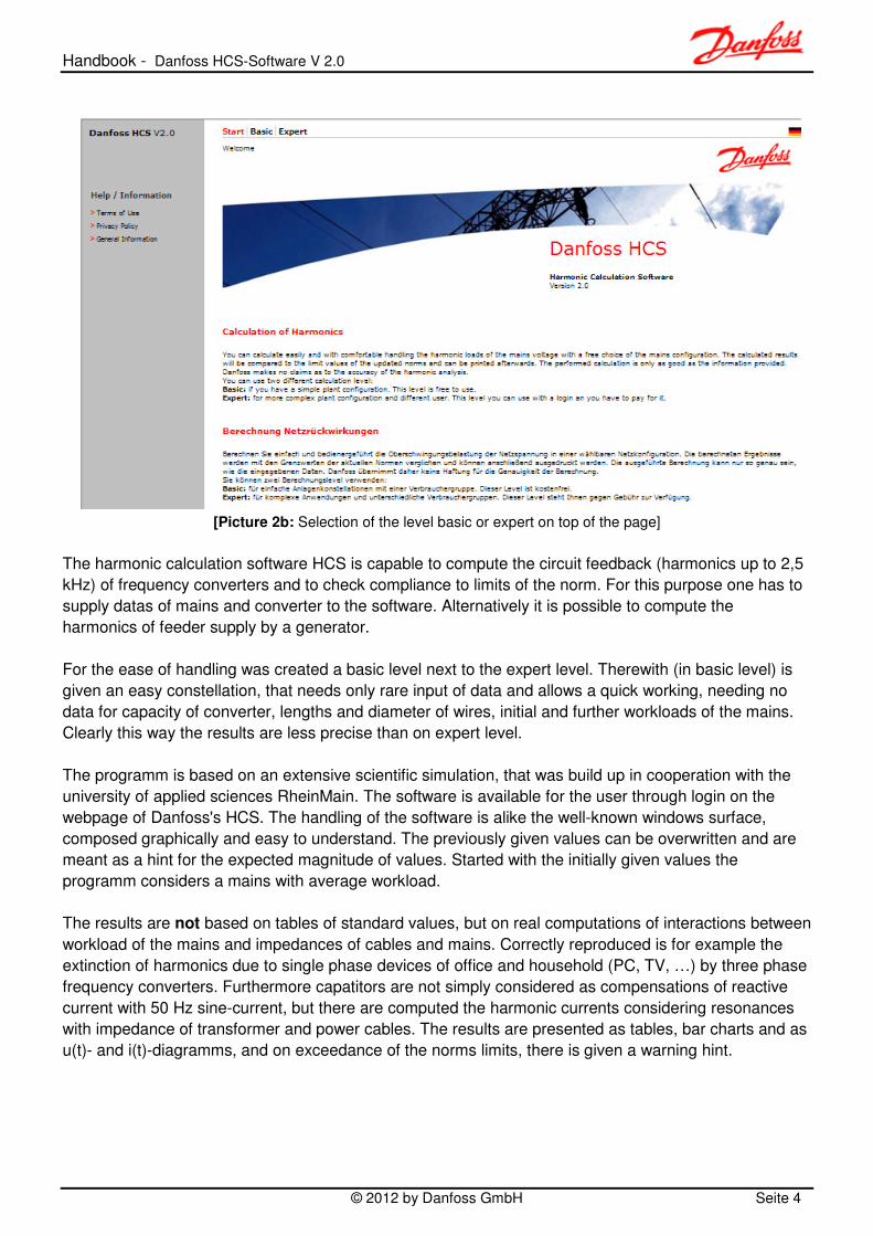
[Picture 2b: Selection of the level basic or expert on top of the page]
The harmonic calculation software HCS is capable to compute the circuit feedback (harmonics up to 2,5
kHz) of frequency converters and to check compliance to limits of the norm. For this purpose one has to
supply datas of mains and converter to the software. Alternatively it is possible to compute the
harmonics of feeder supply by a generator.
For the ease of handling was created a basic level next to the expert level. Therewith (in basic level) is
given an easy constellation, that needs only rare input of data and allows a quick working, needing no
data for capacity of converter, lengths and diameter of wires, initial and further workloads of the mains.
Clearly this way the results are less precise than on expert level.
The programm is based on an extensive scientific simulation, that was build up in cooperation with the
university of applied sciences RheinMain. The software is available for the user through login on the
webpage of Danfoss's HCS. The handling of the software is alike the well-known windows surface,
composed graphically and easy to understand. The previously given values can be overwritten and are
meant as a hint for the expected magnitude of values. Started with the initially given values the
programm considers a mains with average workload.
The results are not based on tables of standard values, but on real computations of interactions between
workload of the mains and impedances of cables and mains. Correctly reproduced is for example the
extinction of harmonics due to single phase devices of office and household (PC, TV, …) by three phase
frequency converters. Furthermore capatitors are not simply considered as compensations of reactive
current with 50 Hz sine-current, but there are computed the harmonic currents considering resonances
with impedance of transformer and power cables. The results are presented as tables, bar charts and as
u(t)- and i(t)-diagramms, and on exceedance of the norms limits, there is given a warning hint.

Handbook - Danfoss HCS-Software V 2.0
© 2012 by Danfoss GmbH Seite 5
2. Selection of circuit
[Picture 3b: Selection between feeding by transformer or generator]
On appearance of this graphic, you can choose between feeder supply by transformer or generator.
The active feeder supply is marked in bright colours.
On expert level you additionally can take the following into account:
• ohmic and inductive resistance of cables
• internal resistance of a superiour mains at medium-high voltage
• background distortion of the mains
• other types of converters and B12-rectifiers
• active and passive harmonic filters
• linear workloads
• etc.

Handbook - Danfoss HCS-Software V 2.0
© 2012 by Danfoss GmbH Seite 6
3. Data for Mains
[Picture 4b: Input of data for the mains]
V0 Mesh voltage (phase/phase) in [V] on the low voltage side of the mains's
transformer at idle run. The input value has to be inbetween 200V and 800V. The
mains with 120V star point voltage can be presented as mesh voltage using
120V*√3=208V.
To achieve as realistic results as possible in basic level, the background distortion
of the mains's voltage at idle run is assumed to be constant at THDu=2%. In expert
level variable values for THDu can be entered.
f Frequency of the mains. It is possible to choose 50Hz or 60Hz.
SN Nominal power resp. rated power of the mains's transformer, using the unit [kVA].
Its nominal current INTr can be concluded from the equation 0*3
1000*
V
SI N
NTr = ,
where SN is given in [kVA], the mesh voltage V0 in [V] und INTr in [A].
The short circuit power of the mains at medium-high voltage is for basic level
assumed to be ∞ (infinitely high).
ek Short circuit voltage uk resp. ek of the mains's transformer, using the unit [%].
The input value has to be inbetween 2,0 and 25%.
If only the short circuit current IKS of the mains's transformer is given, the short
circuit voltage ek in [%] can be calculated using ek=100*INTr/IKS (for INTr look the
notes for SN). The ohmic part ur resp. er of ek is for basic level assumed to be
constant at 1,5%. 22
rxk eee += has to hold.

Handbook - Danfoss HCS-Software V 2.0
© 2012 by Danfoss GmbH Seite 7
[Picture 5b: Input of data for the generator]
V0 Mesh voltage (phase/phase) in [V] on the low voltage side of the generator at idle run.
The input value has to be inbetween 100V and 1400V. A generator with star point
voltage of 120V can be represented with 120V*√3=208V as mesh voltage.
f Frequency of the generator. You can choose between 50Hz and 60Hz.
SN Nominal power resp. rated power of the generator in [kVA].
Its nominal current INGen is computed using the equation 0*3
1000*
V
SI N
NGen = with SN in
[kVA], mesh voltage V0 in [V] und INGen in [A].
xd“ Relative subtransient reactance of the generator in [%]
x0 Relative zero reactance of the generator in [%]

Handbook - Danfoss HCS-Software V 2.0
© 2012 by Danfoss GmbH Seite 8
4. Input data for FC1 (frequency converter)
[Picture 6b: Direct input of data for frequency converters]
PN1 Achieved shaft power of the engine in [kW] on nominal operating is entered, instead of
the apparent power of the converter on input or output.
PN1 is the sum of all nominal engine shaft powers of converter-fed motors:
∑= MotNN PP,1 Here are meant the nominal shaft powers indicated on the type label.
Not every motor and every frequency converter is computed singularly, but one big
frequency converter, whose power is the sum of the single ones. The motors, too, are
combined together to a summed shaft power PN1. The entered value has to be
inbetween 0,1kW and 250% of the transformers nominal power (PN1≤0,8SN makes
sense).
For Danfoss-converters the input of data on the FC1-mask can alternatively be given
by type name and amount/quantity of used converters like on picture 7. PN1 is then
given a value adjusted to the converters.

Handbook - Danfoss HCS-Software V 2.0
© 2012 by Danfoss GmbH Seite 9
ED1 Percental occupancy rate ED1 of the converter in [%].
ED1 considers a partial load operation of converters and motors. For nominal workload is
entered ED1=100, cause then ED1=100%. For several drives there has to be generated
the average.
On partial load operation the product of torque M and number of revolutions n (rotations
per minute) is decisive. %100**1
NN n
n
M
MED = . If on M=100%*MN1 appear only
n=70%nN or appear 70%MN on 100%nN, then ED1=70% in both cases.
Lk1 Relative short circuit voltage of the line commutation inductivity in [%].
Lk1 determines the value of the line commutation inductivity in [H], that is located between
mains and frequency converter. On Danfoss-converters it can even afterwards be
provided as front end inductivity.
If the value of the inductivity is given as relative short circuit voltage, then this value can
be input into the Lk1-field, in expression Lk1=2,5 for the relative short circuit voltage
uk=2,5%.
If only the inductivity Lk in [H] of the mains commutation inductivity is known, then it is
possible to work out Lk1 in [%] using 100*
3
****2
0
1 V
ILfL Nk
k
π=
.
Thereby is to use the nominal current IN of the inductivity. The nominal current should
coincide with the input current of the frequency converter.
The input value has to be between 0 and 12.
LG1 Relative short circuit voltage in [%] of the smoothing inductivity on the side of direct
current. This inductivity is located in the direct current circuit of the frequency converter.
The input of LG1 is obsolete for the user if he chooses the converters using Danfoss's
listing, where the LG-values are preprogrammed.
For further cases the relative value LG1 in [%] has to be provided according to the
equation 100*
3
****2
0
1 V
ILfL NG
G
π=
, instead of the real value of the inductivity LG in
[H].
Thereby IN is the nominal current on the input of the frequency converter.
The input value has to be between 0 and 25.

Handbook - Danfoss HCS-Software V 2.0
© 2012 by Danfoss GmbH Seite 10
5. Selection of FC1 from a list
[Picture 7b: Input of data for frequency converters using Danfoss's lists]
On the very left is choosen the series of frequency converters, while afterwards in the table on
left hand side is entered the amount of used converters into the table of converters. The converters are
later presented in the protocol after calculation of the simulation. For motors is presumed a size fitting to
the converters. PN1 is then the sum of all shaft powers of the motors. Not every motor and every
frequency converter is computed singularily, but one big frequency converter whose power is concluded
from the whole of the single ones.

Handbook - Danfoss HCS-Software V 2.0
© 2012 by Danfoss GmbH Seite 11
6. Overview / Start calculation
[Picture 8b: Start of calculation]
To start the calculation you click onto the button „Overview“ below „Calculation“ and you get the above
picture with an overview over the entered data. Afterwards the calculation of the simulation is started
clicking on „Start calculation“, which takes about 10 seconds.

Handbook - Danfoss HCS-Software V 2.0
© 2012 by Danfoss GmbH Seite 12
7. Results
[Picture 9b: Results]
After termination of the simulation-calculation, the above picture appears. By clicking on the shown
measuring instruments, you get a bar chart and the time development of voltage or current.
Choosing the functionality „Protocol“, the informations according to picture 11 to 16 are at your disposal.

Handbook - Danfoss HCS-Software V 2.0
© 2012 by Danfoss GmbH Seite 13
8. Protocol
[Picture 10b: Selection of a norm for the harmonics]
After the selection of the button „Protocol“, has to be chosen the norm, that shall be decisive for the
comparison of the computed values with norm limits.

Handbook - Danfoss HCS-Software V 2.0
© 2012 by Danfoss GmbH Seite 14
[Picture 11b: Start of the protocol with documentation of the input data]

Handbook - Danfoss HCS-Software V 2.0
© 2012 by Danfoss GmbH Seite 15
[Picture 12b: Spectrum of amplitudes of the transformers current]
At the beginning is at disposal the spectrum of amplitudes for different frequencies of the transformers
current. A comparison to values of the norm only takes place if an IEEE-norm was choosen. Using the
table, harmonic currents can be computed:
In this example the 5th component has a relative size of 38,65%, an reference value of I1eff=330,01A and
an absolute value of I5=330,01A*38,65% =127,55A. I1eff is given below the above table.
[Picture 13b: Time function of the transformers current]
The time function of the transformers current is presented in [A] over a time period of completely 30ms.

Handbook - Danfoss HCS-Software V 2.0
© 2012 by Danfoss GmbH Seite 16
[Picture 14b: Spectrum of amplitudes of the transformers voltage]
Using the table, one can compute the harmonics of the voltage:
In this example the 5th component has the relative magnitude of u5=0,81%, an reference value of
U1eff=229,88V and the absolute value of U5=0,81%*229,88V=1,862V. U1eff is given below the above
table.

Handbook - Danfoss HCS-Software V 2.0
© 2012 by Danfoss GmbH Seite 17
[Picture 15b: Spectrum of amplitudes of the transformers voltage in comparison to norm limits]
The table lists the calculated values and the ones allowed by the choosen norm.
Values exceeding the limits are marked in red colour.
[Picture 16b: Time function of the transformers voltage]
The time function of the transformers voltage is presented in [V] over a time period of completely 30ms.