Damage and Constitutive Modeling for Impact Simulation of ... · 1 Damage and Constitutive Modeling...
29
1 Damage and Constitutive Modeling for Impact Simulation of Random Fiber Composites Haeng-Ki Lee and Srdan Simunovic Computational Materials Science Group Oak Ridge National Laboratory www-explorer.ornl.gov September 14, 1999 Viewgraph for the Third ACC Energy Management Research Meeting
Transcript of Damage and Constitutive Modeling for Impact Simulation of ... · 1 Damage and Constitutive Modeling...
1
Damage and Constitutive Modeling for Impact Simulation of Random Fiber Composites
Haeng-Ki Lee and Srdan Simunovic
Computational Materials Science Group
Oak Ridge National Laboratory
www-explorer.ornl.gov
September 14, 1999
Viewgraph for the Third ACC Energy Management Research Meeting
2
Outline
Fundamental issues on progressive crushing in RFPCs under impact loading
Micromechanical material models
Damage evolution
Numerical simulations and experimental comparison
Finite element implementation for impact simulation
Future efforts
3
Fundamental issues on progressive crushing in RFPCs under impact loading
Damage evolution under impact
Failure mechanisms
Energy dissipation
Failure prediction and damage constitutive modeling for composite structures
4
Damage constitutive models
Based on micromechanical formulation and combination of micro- and macro-mechanical damage criteria
Ensemble volume averaging process and effects of eigenstrains
Two- and three-dimensional damage constitutive models
Implemented into finite element code DYNA3D to simulate crashworthiness of composites
5
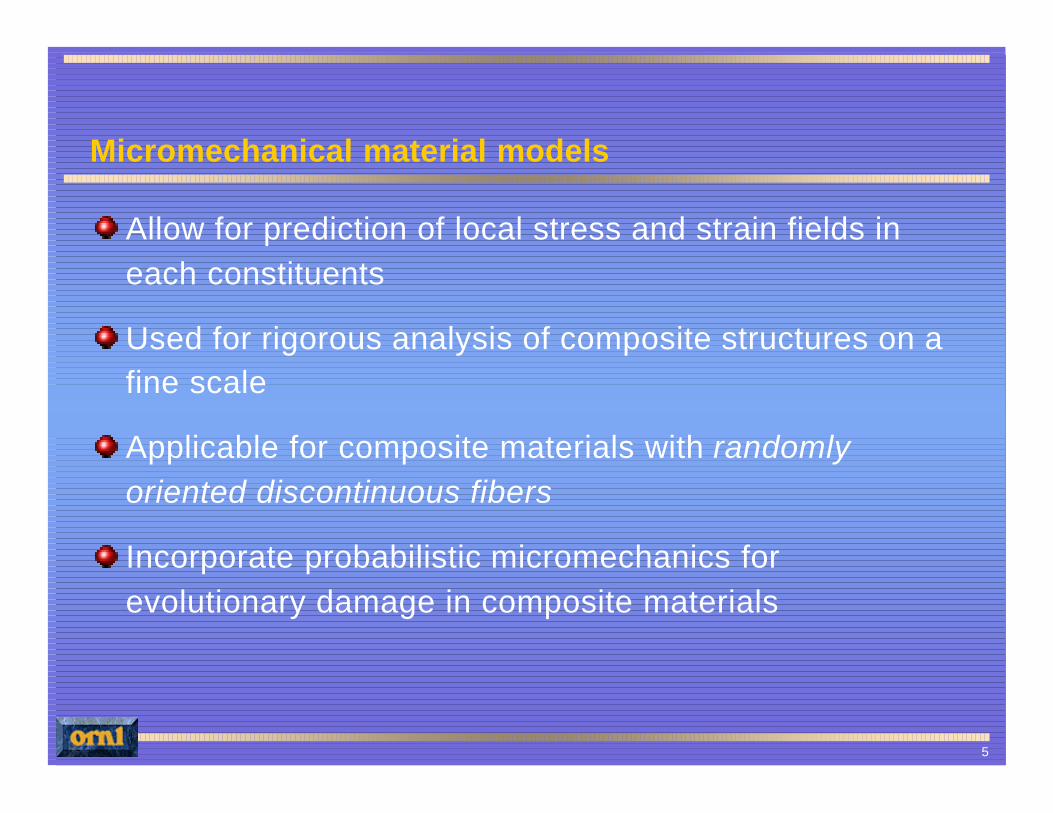
Micromechanical material models
Allow for prediction of local stress and strain fields in each constituents
Used for rigorous analysis of composite structures on a fine scale
Applicable for composite materials with randomly oriented discontinuous fibers
Incorporate probabilistic micromechanics for evolutionary damage in composite materials
6
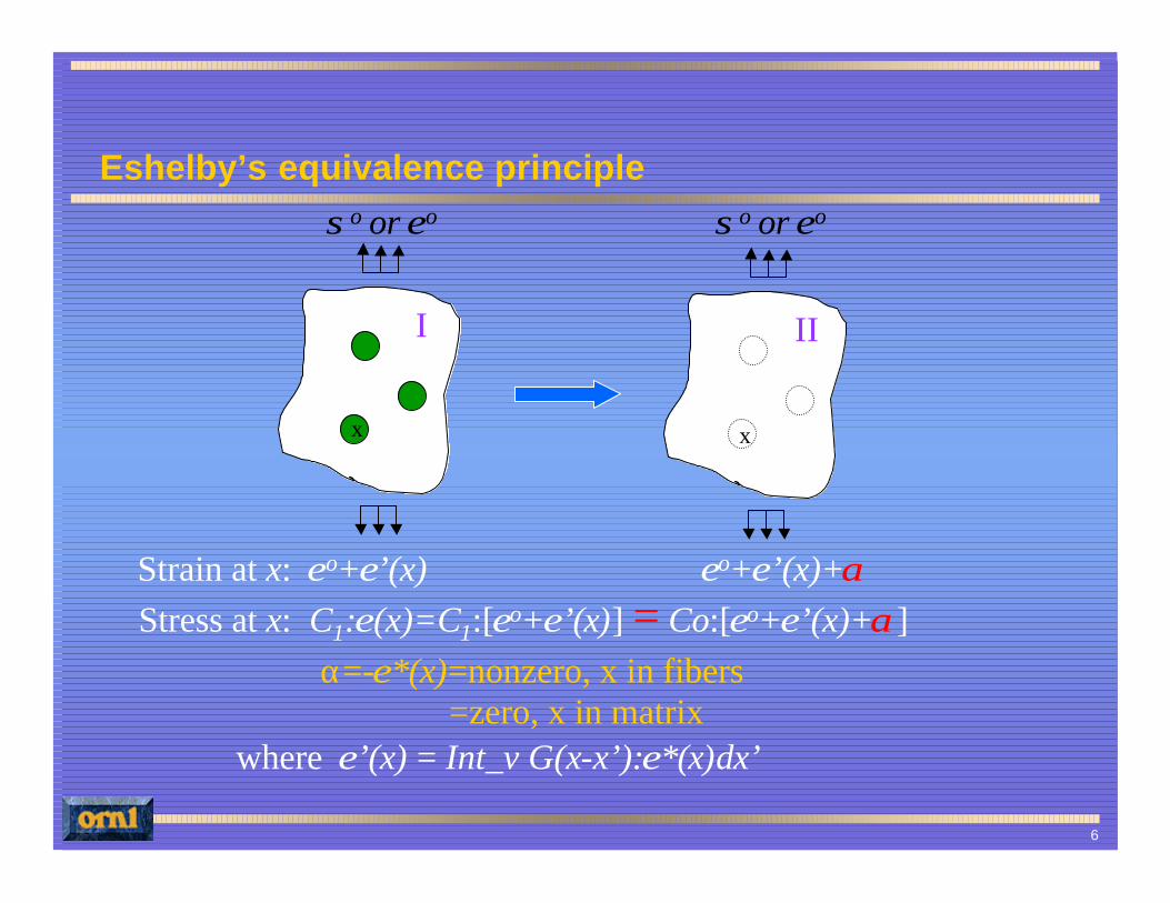
Eshelby’s equivalence principle
Strain at x: εo+ε’(x) εo+ε’(x)+αStress at x: C1:ε(x)=C1:[εo+ε’(x)] = Co:[εo+ε’(x)+α]
α=-ε*(x)=nonzero, x in fibers=zero, x in matrix
where ε’(x) = Int_v G(x-x’):ε*(x)dx’
I II
x x
σo or εo σo or εo
7
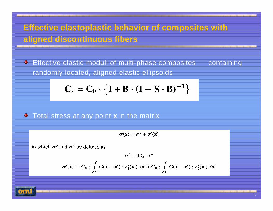
Effective elastoplastic behavior of composites with aligned discontinuous fibers
Effective elastic moduli of multi-phase composites containing randomly located, aligned elastic ellipsoids
Total stress at any point x in the matrix
8
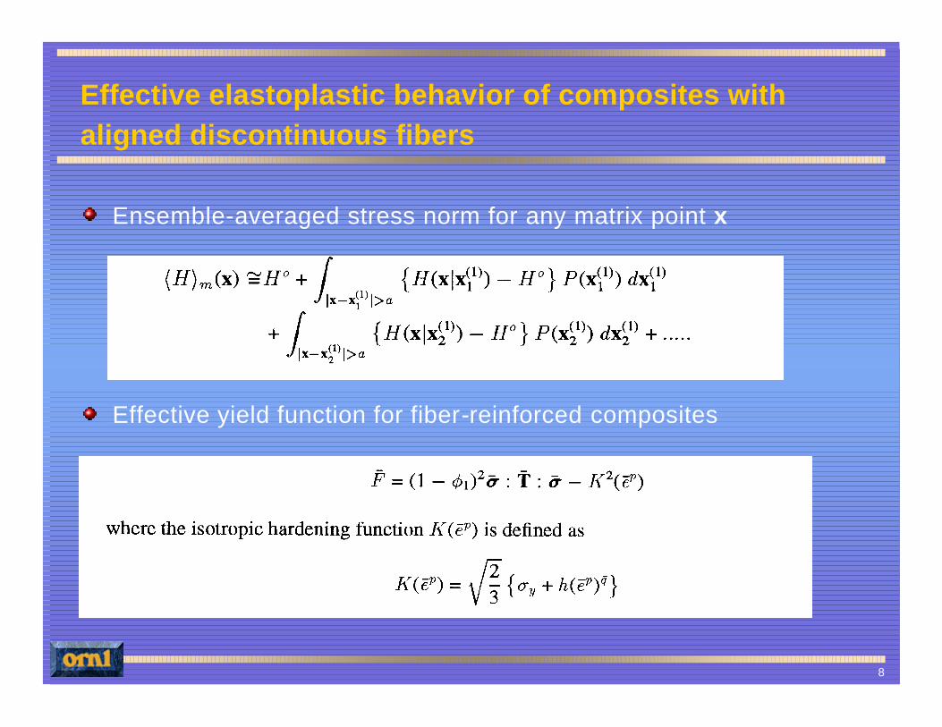
Effective elastoplastic behavior of composites with aligned discontinuous fibers
Ensemble-averaged stress norm for any matrix point x
Effective yield function for fiber-reinforced composites
9
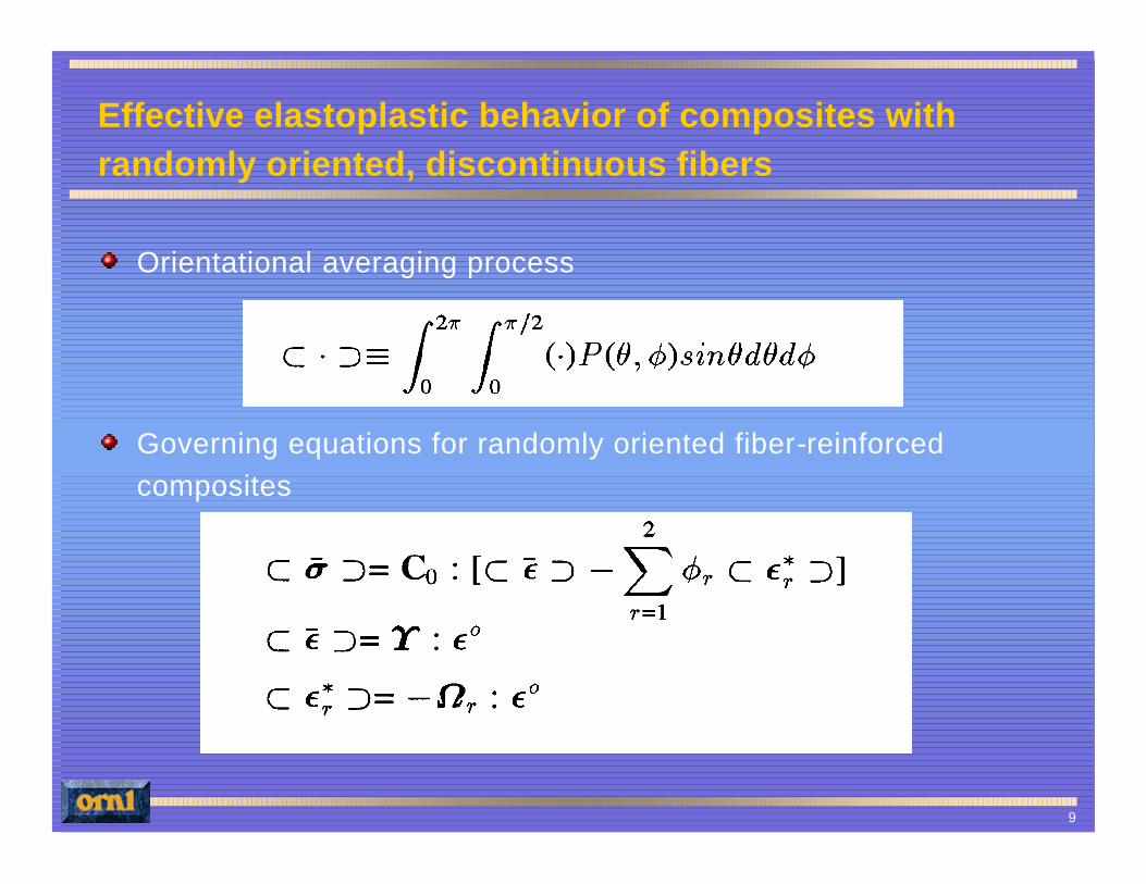
Effective elastoplastic behavior of composites with randomly oriented, discontinuous fibers
Orientational averaging process
Governing equations for randomly oriented fiber-reinforced composites
10
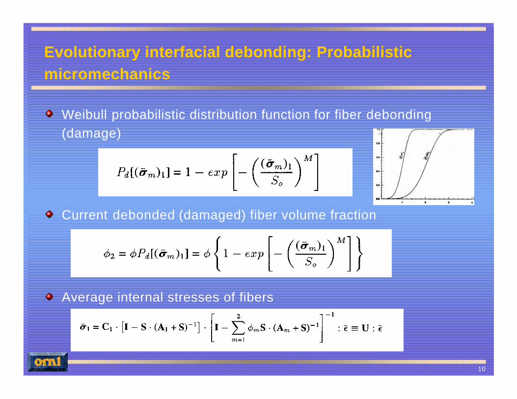
Evolutionary interfacial debonding: Probabilistic micromechanics
Weibull probabilistic distribution function for fiber debonding (damage)
Current debonded (damaged) fiber volume fraction
Average internal stresses of fibers
11
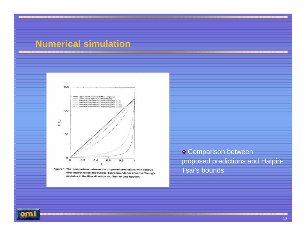
Numerical simulation
Comparison between proposed predictions and Halpin-Tsai’s bounds
12
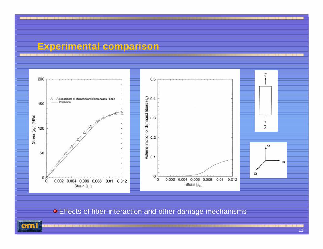
Experimental comparison
Effects of fiber-interaction and other damage mechanisms
13
Finite element implementation for impact simulation
Implementation into explicit finite element code DYNA3D, since impact simulation requires a very small time step integration
Strain driven algorithm to implement into displacement based finite element code DYNA3D
Micromechanical iterative algorithm for progressive damage model
Prediction of dynamic response of composite structures and elimination of need for expensive large-scale experiments
14
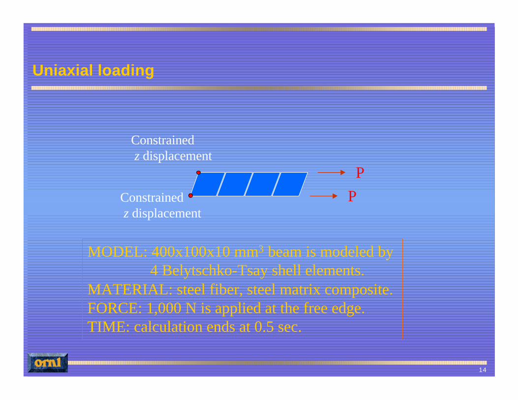
Uniaxial loading
MODEL: 400x100x10 mm3 beam is modeled by 4 Belytschko-Tsay shell elements.
MATERIAL: steel fiber, steel matrix composite.FORCE: 1,000 N is applied at the free edge.TIME: calculation ends at 0.5 sec.
P
P
Constrained z displacement
Constrained z displacement

15
Impact simulation
Displacement in the x-direction during impact
User material Material # 1 (elastic)
16
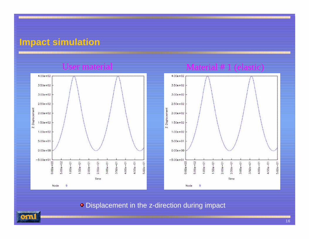
Impact simulation
Displacement in the z-direction during impact
User material Material # 1 (elastic)
17
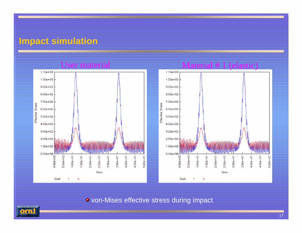
Impact simulation
von-Mises effective stress during impact
User material Material # 1 (elastic)
18
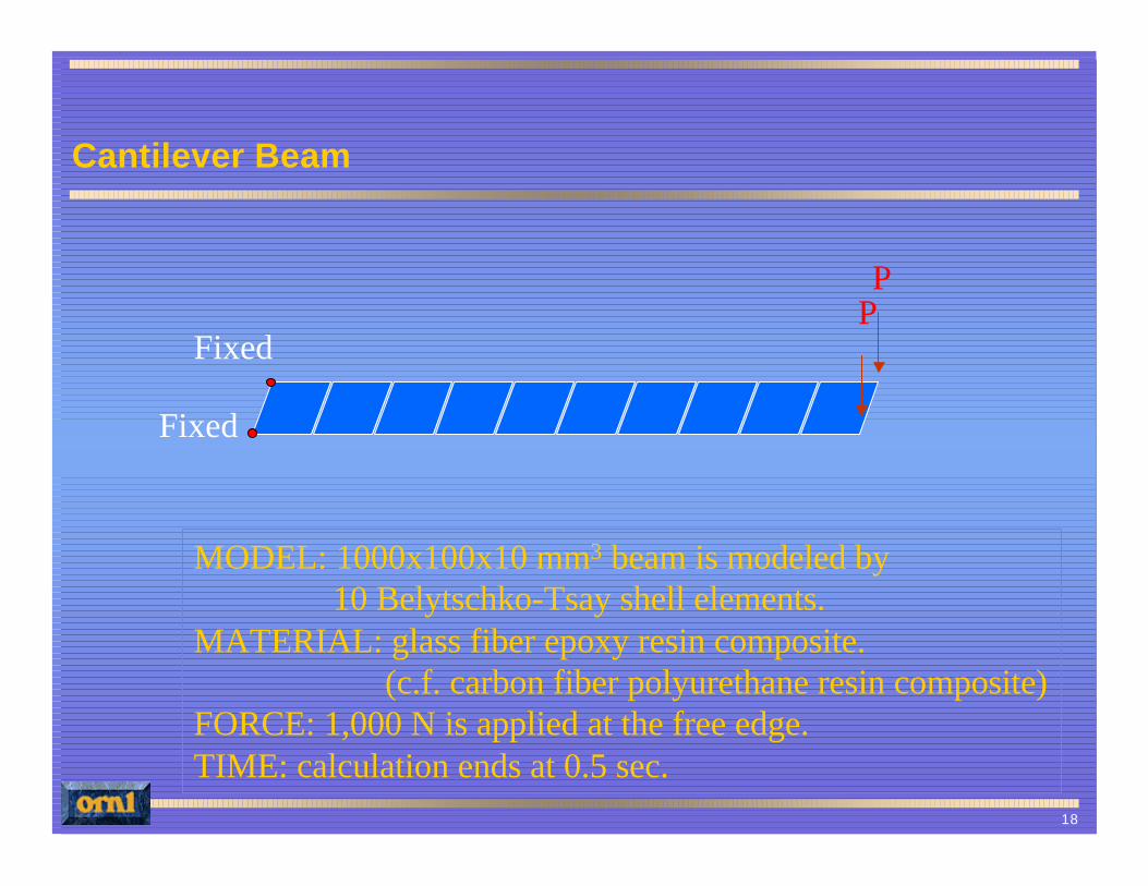
Cantilever Beam
MODEL: 1000x100x10 mm3 beam is modeled by 10 Belytschko-Tsay shell elements.
MATERIAL: glass fiber epoxy resin composite.(c.f. carbon fiber polyurethane resin composite)
FORCE: 1,000 N is applied at the free edge.TIME: calculation ends at 0.5 sec.
PP
Fixed
Fixed
19
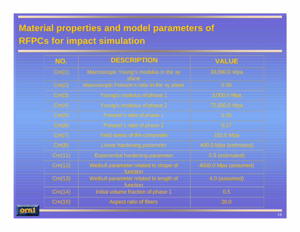
NO. DESCRIPTION VALUECm(1) Macroscopic Young’s modulus in the xy
plane33,000.0 Mpa
Cm(2) Macroscopic Poisson’s ratio in the xy plane 0.30
Cm(3) Young’s modulus of phase 1 3,000.0 Mpa
Cm(4) Young’s modulus of phase 2 72,000.0 Mpa
Cm(5) Poisson’s ratio of phase 1 0.35
Cm(6) Poisson’s ratio of phase 2 0.17
Cm(7) Yield stress of the composite 150.0 Mpa
Cm(8) Linear hardening parameter 400.0 Mpa (estimated)
Cm(11) Exponential hardening parameter 0.5 (estimated)
Cm(12) Weibull parameter related to shape of function
4000.0 Mpa (assumed)
Cm(13) Weibull parameter related to length of function
4.0 (assumed)
Cm(14) Initial volume fraction of phase 1 0.5
Cm(15) Aspect ratio of fibers 20.0
Material properties and model parameters ofRFPCs for impact simulation
20
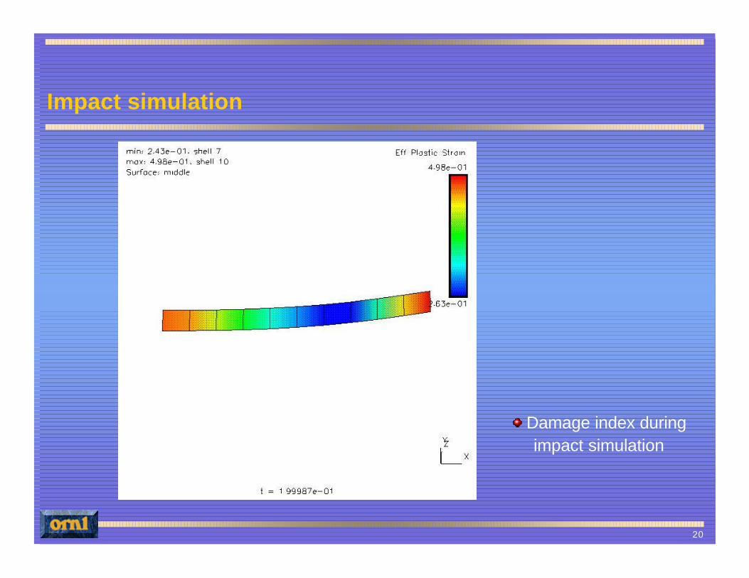
Impact simulation
Damage index during impact simulation
21
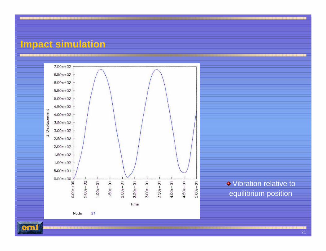
Impact simulation
Vibration relative to equilibrium position
22
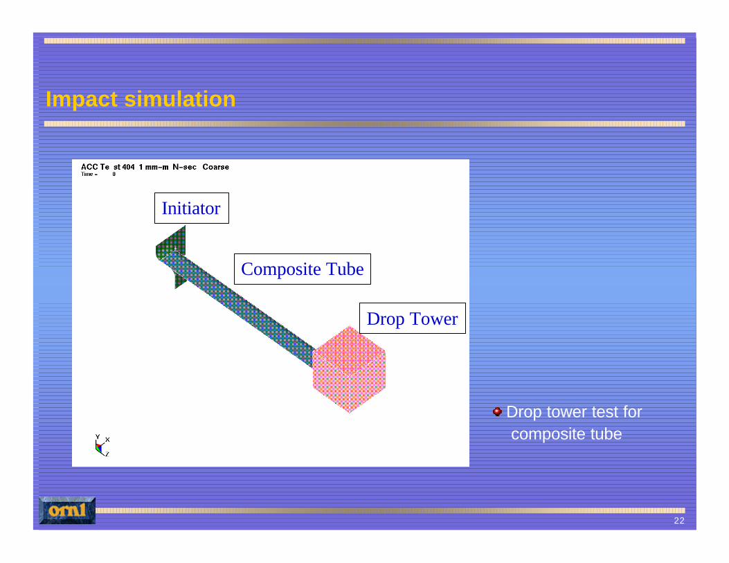
Impact simulation
Drop tower test for composite tube
Drop Tower
Composite Tube
Initiator
23
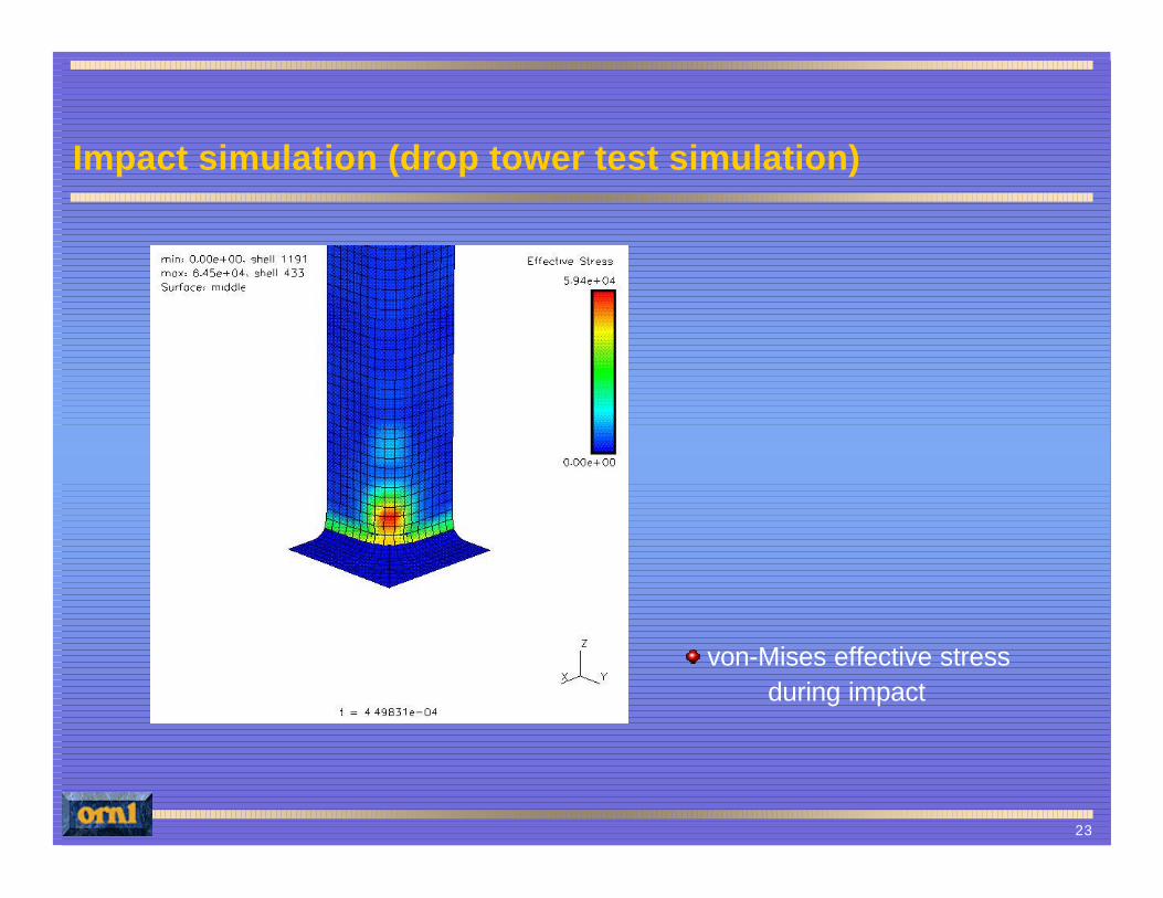
Impact simulation (drop tower test simulation)
von-Mises effective stress during impact
24
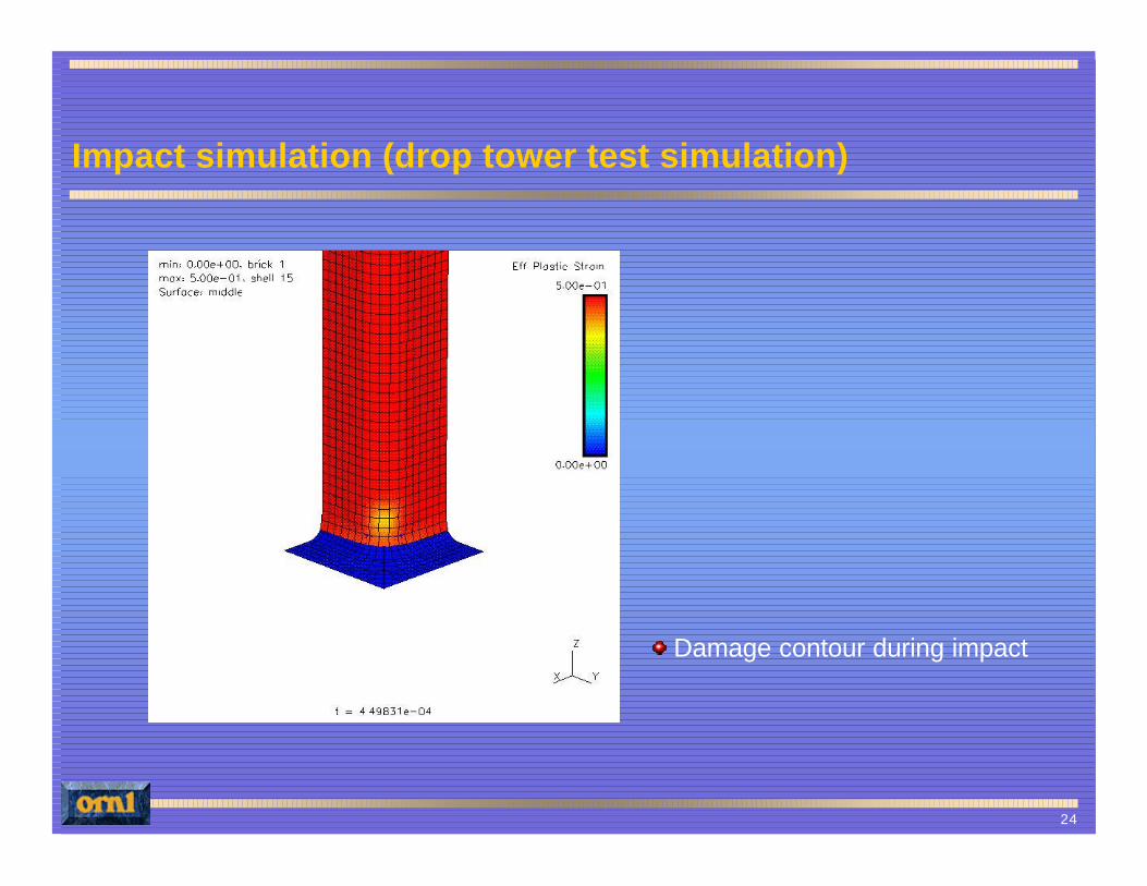
Impact simulation (drop tower test simulation)
Damage contour during impact
25
Chances of success of the chosen micro-mechanics approach for RFPCs
Damage constitutive model based on micro-mechnical framework and micro- and macro-mechanical damage criteria to predict damage behavior of RFPCs
Composite materials reinforced with randomly oriented discontinuous fibers
Analytical bounds and experimental data
Experimental work for determining model parameters and damage variables
26
Chances of success of the chosen micro-mechanics approach for RFPCs
Large deformation formulation for dealing with negative stiffness zone
Examples of uniaxial, biaxial and triaxial tensions and compressions
Interaction effects among constituents and effect of matrix microcracks on overall stiffness
Evolutions of microcrack density and volume fraction of damaged fibers
27
Nondestructive testing to validate micro-mechanics model
Acoustic emission (AE) analysis for monitoring damage initiation and evolution under static and dynamic loads
Impact damage characterization using drop weight test frame and NDE technique
Correlation between received acoustic wave and damage models in monitoring damage evolution
28
Future efforts
Applying two-dimensional/distributive orientational averaging process for transversely isotropic composites with randomly oriented fibers in the 1-2 plane
Modeling of microcrack-weakened composites
Development of new failure criteria for randomly oriented, discontinuous fiber composites under impact loading
29
Future efforts
Extending the present damage to be able to account for fiber interactions for the composite with high fiber volume fraction
Employing large deformation theory for high ductility of organic matrix composite materials
Modeling of tube crush tests to determine the validity of the current damage constitutive models
Nondestructive testing to validate micromechanicsmodel