Dale Avenue Pump Station Wet Well Rehabilitation Project ...
53
TECHNICAL MEMORANDUM CITY OF SAN MATEO DALE AVENUE PUMP STATION WET WELL CONDITION ASSESSMENT Prepared for: City of San Mateo Prepared by: Daniel Day, V&A Consulting Engineers Michael Johannessen, P.E., V&A Consulting Engineers Nicole Kwan, V&A Consulting Engineers Reviewed by: Noy Phannavong, P.E., V&A Consulting Engineers Glenn Willson, P.E., V&A Consulting Engineers Date: November 25, 2014 V&A Project No. 14-0206
Transcript of Dale Avenue Pump Station Wet Well Rehabilitation Project ...

TECHNICAL MEMORANDUM
CITY OF SAN MATEO
DALE AVENUE PUMP STATION WET WELL
CONDITION ASSESSMENT
Prepared for: City of San Mateo
Prepared by: Daniel Day, V&A Consulting Engineers
Michael Johannessen, P.E., V&A Consulting Engineers
Nicole Kwan, V&A Consulting Engineers
Reviewed by: Noy Phannavong, P.E., V&A Consulting Engineers
Glenn Willson, P.E., V&A Consulting Engineers
Date: November 25, 2014
V&A Project No. 14-0206

V&A Project No. 14-0206 Introduction 2
INTRODUCTION 1.0
V&A Consulting Engineers (V&A) was retained by the City of San Mateo (City) to perform a condition
assessment of the wet wells at the Dale Avenue Pump Station within the City in preparation for
facility rehabilitation. The wet wells contain several slide gates that are reportedly severely corroded.
Of particular interest is the condition of Slide Gate No. 3 between the two wet wells. Also of interest
is the condition of unlined concrete and uncoated steel within the wet wells.
The condition assessment consisted of visual observations with photographic documentation of the
interior surfaces of the structure and associated components. A pole-mounted zoom camera was
used to record video of the condition of walls and structures in the wet wells below the concrete
platforms that were used to conduct the assessment. The depth to reinforcing steel was measured in
the concrete walls and the platform floors.
Condition assessment activities were completed in two site visits on September 30 and October 20,
2014. An aerial view of the Dale Avenue Pump Station site and the San Mateo Water Quality Control
Plant is shown in Figure 1. A closer aerial image of the pump station building is shown in Figure 2.
Figure 1. Aerial view of the Dale Avenue Pump Station and vicinity.

City of San Mateo
Dale Avenue Pump Station Wet Well Condition Assessment
V&A Project No. 14-0206 Introduction 3
Figure 2. Aerial view of the Dale Avenue Pump Station complex.

V&A Project No. 14-0206 Dale Avenue Pump Station Layout 4
DALE AVENUE PUMP STATION 2.0LAYOUT
The current Dale Avenue Pump Station was built in 1990 on the site of a previous pump station. The
pump station conveys flows eastward to the San Mateo Water Quality Control Plant (WQCP) through
two separate force mains. Wastewater flows by gravity into the pump station from a series of
manholes on the east and west sides of Patricia Avenue. The influent wastewater first enters the
underground Control Structure on the west side of the pump station and is distributed into the two
wet wells from there. A system of six hydraulically operated sluice gates was originally installed in the
Control Structure and wet wells to provide control of flow routing. Subsequently, because of
corrosion of the gate operators and hydraulic tubing, three of the gates were closed off with blind
flanges and two of the gates were removed.
The City is planning to rehabilitate the Dale Avenue Pump Station. The intent of the condition
assessment is to determine the condition of concrete structures, metal appurtenances, and of the
only remaining sluice gate, which is Sluice Gate 3 between the two wet wells. V&A was tasked with
the condition assessment. Cleaning and preparation of the wet wells and wet well pump intakes,
including removal of debris and de-ragging Pump 6, was conducted by Presidio Services, Inc., during
the same timeframe as the condition assessment.
The access to Wet Well 1 (WW1) and Wet Well 2 (WW2) is through at-grade hatches located on the
west side of the pump station. The hatches are approximately 10 feet above the west ends of
concrete platforms along the wall dividing the two wet wells. A confined space entry was conducted
for each wet well in order to visually assess the structures as accessible from the platforms. A pole-
mounted video camera was used to record conditions below the platforms. Figure 3 through Figure 5
show the wet wells and Control Structure at the Dale Avenue Pump Station.

City of San Mateo
Dale Avenue Pump Station Wet Well Condition Assessment
V&A Project No. 14-0206 Dale Avenue Pump Station Layout 5
Figure 3. Dale Avenue Pump Station section looking north.
Figure 4. Dale Avenue Pump Station section looking west.

City of San Mateo
Dale Avenue Pump Station Wet Well Condition Assessment
V&A Project No. 14-0206 Dale Avenue Pump Station Layout 6
Figure 5. Dale Avenue Pump Station plan view schematic.
N

V&A Project No. 14-0206 Methods and Procedures 7
METHODS AND PROCEDURES 3.0
3.1 Access and Confined Space Entry
The interior of the Dale Avenue Pump Station wet wells are considered permit-required confined
spaces. The confined space entry evaluations were made using precautions including permit
procedures, ventilation and monitoring equipment, and appropriate personal protective equipment.
Access into the wet wells was by an extension ladder that was placed on the platform and secured at
the entry hatches. A self-retracting lifeline (SRL) was used to provide fall protection and emergency
retrieval capabilities.
3.2 Visual Evaluation
The primary investigative method was to conduct visual examinations supplemented with digital
photographs and videos. The visual assessment focused on the condition of metal appurtenances,
coatings, and reinforced concrete surfaces. Structural defects such as large cracks, spalls, and
corrosion of reinforcing steel and metal fasteners were noted when found. The assessments are
subjective in nature and are based on V&A’s extensive experience evaluating concrete and steel
structures in the water and wastewater industry.
3.3 Concrete Evaluation Techniques
3.3.1 Sounding
Sounding a surface refers to tapping the concrete surface with a chipping hammer and listening for
discontinuities beneath the surface. Locations for sounding tests were selected at the discretion of
the evaluator.
3.3.2 Penetration Tests
Penetration tests involve applying a consistent level of force from a chipping hammer to the concrete
surface, until sound material is reached, and then measuring the depth of the resulting cavity. The
cavity depth provides an estimate of the integrity and condition of the concrete surfaces. Typically, as
concrete deteriorates, the cement mortar begins to lose integrity and becomes soft. The sound
produced by the hammer strike also provides qualitative information on the presence of voids below
the surface.

City of San Mateo
Dale Avenue Pump Station Wet Well Condition Assessment
V&A Project No. 14-0206 Methods and Procedures 8
3.3.3 Depth to Steel Reinforcement
Measurements of the depth of concrete cover over the
reinforcing steel were made using a Profometer 5+ Rebar
Detection System, manufactured by Proceq USA, Inc. (Figure 6).
The Profometer uses non-destructive pulse-induction technology
as the measuring method. Concrete cover depth is crucial to the
corrosion protection of reinforced concrete structures. The
greater the concrete cover thickness, the less likely that the
reinforcing steel will be subjected to corrosion.
3.3.4 Envirosight QuickView Haloptic Pole Camera
The portions of the wet wells below the deck were evaluated using the
Envirosight Quickview pole camera (Figure 7). This system is an
efficient tool for evaluating structures that are particularly difficult to
access. The zoom camera system is pole-mounted and can be lowered
into a structure by extending the telescoping pole. The maximum
extension length is 25 feet. The QuickView camera is equipped with
zoom capabilities and halogen lighting to allow video documentation of
the structure. Digital images are recorded as movies or still shots. In
this situation, the pole camera was extended below the platform decks
to image the walls and the slide gates in the lower wet wells. The
camera system is capable of providing clear images over 100 feet from
the camera.
3.3.5 Concrete pH Sample
The pH of the exposed concrete surface indicates the corrosivity of the environment. Concrete
fragments were collected from WW1 at a floor location where a relatively large area of concrete was
exposed. The pH was measured using an ECO Testr pH2 handheld electronic meter. The pH probe
was calibrated prior to testing using pH 4.00, 7.00, and 10.00 standard buffer solutions.
V&A has developed a table correlating concrete pH with corrosivity of the environment, as shown in
Table 3-1. The data in Table 3-1 is derived from past experience and a review of technical literature,
such as ACI International Technical Document C-24, “Durable Concrete.” The concrete pH also
correlates well with the overall physical integrity of the concrete surface as a result of cement paste
carbonation and atmospheric hydrogen sulfide vapor attack.
Figure 7. Envirosight
QuickView Pole Camera
Figure 6. Profometer 5+
Rebar Detector

City of San Mateo
Dale Avenue Pump Station Wet Well Condition Assessment
V&A Project No. 14-0206 Methods and Procedures 9
Table 3-1. Concrete pH versus
Environmental Corrosivity
pH Degree of Corrosivity
< 8 Severe
8 to 10 Moderate
10 to 12 Neutral
> 12 Negligible
3.3.6 VANDA™ Concrete Condition Index Rating System
The VANDA™ Concrete Condition Index was created by V&A to provide consistent reporting of
corrosion damage based on qualitative, objective criteria. As shown in Table 3-2, the condition of
concrete corrosion can vary from Level 1 to Level 4 based upon visual observations and field
measurements, with Level 1 indicating the best condition and Level 4 indicating severe damage.
Table 3-2. VANDA™ Concrete Condition Index Rating System
Condition
Rating Description
Representative
Photograph
Level 1
None/Minimal Damage to Concrete
Hardness: No Loss
Surface Profile: No Loss
Cracking: Shrinkage Cracks
Spalling: None
Reinforcing Steel : Not Exposed or Damaged
Level 2
Damage to Concrete Mortar
Hardness: Damage to Concrete Mortar
Surface Profile: Some Loss
Cracking: Thumbnail Sized Cracks of Minimal Frequency
Spalling: Shallow Spalling of Minimal Frequency, Related Reinforcing Steel
Damage
Reinforcing Steel : May Be Exposed but Not Damaged
Level 3
Loss of Concrete Mortar/Damage to Reinforcing Steel
Hardness: Complete Loss
Surface Profile: Large Diameter Exposed Aggregate
Cracking: ¼-inch to ½-inch Cracks, Moderate Frequency
Spalling: Deep Spalling of Moderate Frequency, Related Reinforcing Steel
Damage
Reinforcing Steel: Exposed and Damaged, Can Be Rehabilitated
Level 4
Reinforcing Steel Severely Corroded/Significant Damage to Structure
Hardness: Complete Loss
Surface Profile: Large Diameter Exposed Aggregate
Cracking: ½-inch Cracks or Greater, High Frequency
Spalling: Deep Spalling at High Frequency, Related Reinforcing Steel Damage
Reinforcing Steel: Damaged or Consumed, Loss of Structural Integrity
© 2014 V&A Consulting Engineers, Inc. All rights reserved.

City of San Mateo
Dale Avenue Pump Station Wet Well Condition Assessment
V&A Project No. 14-0206 Methods and Procedures 10
3.4 Coating Sample Analysis
V&A collected two coating samples, one from each wet well. The samples were tested for lead,
chromium, zinc and 13 other Title 22-regulated heavy metals, according to EPA Method 6020A, at
Xenco Laboratories, an environmental-analysis lab in Stafford, Texas. Mercury was tested per EPA
Method 7471A. If lead or other heavy metals are present in the coatings in significant
concentrations, abatement protocols will be required during the surface-preparation phase of
recoating the wet wells.

V&A Project No. 14-0206 Condition Assessment Findings 11
CONDITION ASSESSMENT 4.0FINDINGS
4.1 Wet Wells
4.1.1 Concrete Surfaces
Most of the concrete surfaces in Wet Wells 1 and 2 were originally coated. There appear to be
several layers of coating, all of which are generally deteriorated. The upper layer is peeling and loose
in most locations, while the lower layers are somewhat more adherent. All of the layers have failed in
many locations, and the bare concrete is beginning to corrode. Generalized coating failure has left
large areas of bare concrete visible at the middle and lower elevations above the water line in both
wet wells. In other areas, the coating failure is mostly localized at pinholes and, in particular, at
corners and edges. Blisters in the coating were visible at lower elevations.
Where there has been generalized coating failure, the concrete surfaces have sustained damage to
the mortar with some loss of surface profile. Locations away from the platforms were not accessible
for detailed evaluation, but medium-diameter exposed aggregate was evident. In general, the coating
failure and concrete degradation was worse in WW1. The southeast corner of WW2 may have
erosion damage to the concrete surfaces below the sump pump discharge. There were some
relatively small areas of generalized coating failure on the platform floors.
Coating failure at corners and edges, such as the edges of the platform and the corners of the ceiling
beams, has resulted in loss of mortar hardness and some expansion of the corrosion products at
these locations. Exposed aggregate was visible at some of these locations. Some of the pinholes
also exhibited similar concrete degradation. There was also an apparent split in the coating on the
east wall of WW1, near the water line, that appears to form a “pouch” that collects debris or grease
buildup.
The exposed concrete surfaces in Wet Wells 1 and 2 are rated VANDA Level 2 for concrete condition.
No exposed reinforcing steel was observed. Photo 4-1 through Photo 4-17 show the concrete and
coating conditions in the wet wells.

City of San Mateo
Dale Avenue Pump Station Wet Well Condition Assessment
V&A Project No. 14-0206 Condition Assessment Findings 12
Photo 4-1. Coating failure on WW1 north
wall near water line.
Photo 4-2. WW1 northeast corner with
blistered and failed coating.
Photo 4-3. WW1 east wall. White areas are
exposed concrete.
Photo 4-4. Typical coating deterioration and
concrete corrosion at corners of WW1 roof
beams.
Photo 4-5. WW1 ceiling and north wall. Photo 4-6. WW1 west wall.

City of San Mateo
Dale Avenue Pump Station Wet Well Condition Assessment
V&A Project No. 14-0206 Condition Assessment Findings 13
Photo 4-7. Split in coating on WW1 east wall
may collect debris.
Photo 4-8. Coating failure and bare concrete
with exposed aggregate in WW2.
Photo 4-9. Coating failure and bare concrete
in WW2.

City of San Mateo
Dale Avenue Pump Station Wet Well Condition Assessment
V&A Project No. 14-0206 Condition Assessment Findings 14
Photo 4-10. WW2, blisters at lower levels in
southeast corner.
Photo 4-11. WW2, possible erosion damage
below sump pump discharge.
Photo 4-12. WW2, typical coating blisters
above platform.
Photo 4-13. WW2, southeast corner with
sump pump discharge active.
Photo 4-14. WW2, typical ceiling surfaces. Photo 4-15. WW2 platform, looking east.

City of San Mateo
Dale Avenue Pump Station Wet Well Condition Assessment
V&A Project No. 14-0206 Condition Assessment Findings 15
Photo 4-16. Poorly sealed penetration for
tubing to sluice gate operator in WW2.
Photo 4-17. Coating failure and moderate
concrete degradation at edge of platform in
WW2.
A concrete sample for pH testing was collected from the platform floor in WW1 at a location with a
relatively large area of coating failure. The measured pH was 5.1, confirming that the typical internal
atmosphere of the wet wells is severely corrosive to concrete.
Penetration measurements on the accessible walls of the wet wells revealed that the concrete has
lost hardness to a depth of up to 1/2 of an inch. This indicates moderate deterioration of the
concrete walls. The areas of generalized coating failure and concrete degradation were not
accessible from the platform and may have a somewhat greater depth of degradation. The results of
the penetration tests are summarized in Table 4-1.
Table 4-1. Penetration Test Results
Location Penetration Depth
(in.)
WW1 and WW2 platform floors Up to 1/4
WW1 walls accessible from platform 1/8 to 3/8
WW2 walls accessible from platform Up to 1/2
For corrosion protection of reinforcing steel in water-retaining structures, ACI 350-06, “Code
Requirements for Environmental Engineering Concrete Structures,” states that the minimum depth
of concrete cover over reinforcing steel should be 2 inches. Depths to reinforcing steel were
measured for the accessible wet well walls above the platforms. Measurements are for the vertical
bars, as the horizontal bars were outside the measuring range of the instrument, as were the bars in
the platform floors. The results are summarized in Table 4-2. It should be noted that these results
are based on a few randomly selected point locations; depths in other locations may differ.

City of San Mateo
Dale Avenue Pump Station Wet Well Condition Assessment
V&A Project No. 14-0206 Condition Assessment Findings 16
Table 4-2. Depth to Reinforcing Steel Measurement Summary
Location Rebar Depth (in.)
WW1 south wall 1.8 to 2.3
WW1 east wall 1.7 to 2.0
WW1 west wall 2.3 to 2.5
WW2 north wall 2.5 to 2.8
WW2 east wall 1.9
WW2 west wall 2.5
Some of the measurements are slightly below the minimum depth of 2 inches. Based on the
observed extent of concrete degradation, the reinforcing steel may become susceptible to corrosion
if the concrete corrosion is not mitigated.
4.1.2 Coating Sample Analysis
Coating samples were collected from each wet well and evaluated. One sample was from the south
wall of WW1 and represented the second layer of coating below the surface. This was probably the
previous coating that had been applied prior to the current coating. The other sample was from the
north wall of WW2 near the sluice gate operator and represented the top coating layer. A large area
of the coating was loose and peeling at this location. Table 4-3 summarizes the results of the
samples that were analyzed. The coating sample analysis report is included in Appendix A.
Table 4-3. Summary of Coating Sample Laboratory Results
Metal
TTLC
Maximum
Concentration
(ppm)
Wet Well 1
(ppm)
Wet Well 2
(ppm)
Antimony 500 BRL BRL
Arsenic 500 BRL BRL
Barium 10,000 169 195
Beryllium 75 BRL 0.451
Cadmium 100 BRL BRL
Chromium 2,500 3.34 BRL
Cobalt 8,000 BRL BRL
Copper 2,500 2.52 2.81
Lead 1,000 1.95 3.05
Mercury 20 0.0697 0.171
Molybdenum 3,500 1.97 BRL

City of San Mateo
Dale Avenue Pump Station Wet Well Condition Assessment
V&A Project No. 14-0206 Condition Assessment Findings 17
Metal
TTLC
Maximum
Concentration
(ppm)
Wet Well 1
(ppm)
Wet Well 2
(ppm)
Nickel 2,000 28.4 BRL
Selenium 100 BRL BRL
Silver 500 BRL BRL
Thallium 700 BRL BRL
Vanadium 2,400 2.52 3.69
Zinc 5,000 4.93 3.18
ppm – parts per million BRL – below reporting limit
Based on the results of the coating sample analysis, lead abatement is not required during the
removal of the coating. In addition, the waste generated from the removal of the coating is not
expected to exceed the total threshold limit concentrations (TTLC) maximums for any of the 17 heavy
metals tested for. However, waste produced during coating removal should be tested prior to
transporting it out of the Dale Avenue Pump Station site for disposal. Also, it is possible that
additional (lower) coating layers that exceed the threshold limits may still exist.
4.1.3 Inlet Piping
Based on visual evaluation using the zoom camera, the inlet pipes do not show signs of significant
deterioration. However, the access constraints and debris covering the pipes limited the evaluation.
Photo 4-18 through Photo 4-23 show the condition of the inlet pipes.
Photo 4-18. Large inlet pipe inside WW1. Photo 4-19. Small inlet pipe inside WW1.

City of San Mateo
Dale Avenue Pump Station Wet Well Condition Assessment
V&A Project No. 14-0206 Condition Assessment Findings 18
Photo 4-20. Large inlet pipe inside WW2. Photo 4-21. Small inlet pipe inside WW2.
Photo 4-22. End of large inlet pipe inside
WW2.
Photo 4-23. Weld on large inlet pipe inside
WW2.
4.1.4 Sluice Gate and Stop Logs
The operating mechanism for Sluice Gate 3 inside Wet Well 2 exhibits coating failure and minor to
moderate corrosion. The gate operator does not work per City staff comments. Nuts on the anchor
rods are loose and sound hollow, and the mortar edges have spalled from the base plate. The sluice
gate itself was not visible due to the water level during the evaluations. The top of the gate frame
was visible and did not appear to be significantly corroded; cast lettering was still legible on the
frame. The gate stem guide brackets were covered with debris and their condition could not be
determined. Photo 4-24 through Photo 4-31 show the observations for Sluice Gate 3 from WW2.

City of San Mateo
Dale Avenue Pump Station Wet Well Condition Assessment
V&A Project No. 14-0206 Condition Assessment Findings 19
Photo 4-24. Operator for Sluice Gate 3
inside WW2.
Photo 4-25. Conduit entering operator for
Sluice Gate 3.
Photo 4-26. Coating failure and surface
corrosion at top of Sluice Gate 3 operator.
Photo 4-27. WW2 sluice gate operator,
spalled mortar along base plate.

City of San Mateo
Dale Avenue Pump Station Wet Well Condition Assessment
V&A Project No. 14-0206 Condition Assessment Findings 20
Photo 4-28. Stem bracket for Sluice Gate 3
inside WW2.
Photo 4-29. Top of Sluice Gate 3 guides
projecting above water surface in WW2.
Photo 4-30. Gate channel in Sluice Gate 3
frame.
Photo 4-31. Cast lettering visible on Sluice
Gate 3 guide frame.
The wet wells’ stop log hardware appears to be in relatively good condition. WW1 has two stop log
gates; both appear to be in good condition, though rags and debris seem to easily get caught on the
stop log gates. WW2 has one stop log gate. The seals in the stop log guides are peeling back above
the top of the stop logs. The stop logs have round (possibly stainless steel) pegs on each side that
appear to be in good condition. Photo 4-32 through Photo 4-36 show the condition of the stop logs.

City of San Mateo
Dale Avenue Pump Station Wet Well Condition Assessment
V&A Project No. 14-0206 Condition Assessment Findings 21
Photo 4-32. WW1 stop log gate (north of
two).
Photo 4-33. WW1 stop log gate (south of
two).
Photo 4-34. WW1 stop logs. Photo 4-35. Typical metal peg on WW2 stop
logs.
Photo 4-36. Sealing strips peeling back
inside WW1 stop log guides.

City of San Mateo
Dale Avenue Pump Station Wet Well Condition Assessment
V&A Project No. 14-0206 Condition Assessment Findings 22
4.1.5 Conduits
The conduits inside the wet wells show localized coating failure and corrosion. Some of the clamps
and brackets are also corroded. This applies to the conduits for the sluice gate operator and in
general for the other conduits inside the wet wells. Conduits below the platform appeared to collect
debris near the water line. Photo 4-37 through Photo 4-39 show the typical condition of the conduits
inside the wet wells.
Photo 4-37. Coating failure and corrosion on
conduits in WW2 (typical).
Photo 4-38. Corroded conduit clamp inside
WW2 (typical).
Photo 4-39. Debris on conduits below WW1
platform.

City of San Mateo
Dale Avenue Pump Station Wet Well Condition Assessment
V&A Project No. 14-0206 Condition Assessment Findings 23
4.1.6 Ducting and Miscellaneous Pipes
There are three fiber-reinforced plastic (FRP) ducts inside each wet well; two circular ducts near the
center of the platforms and one rectangular duct over the east end of the platforms. The rectangular
ducts have experienced minor degradation with some coating failure and delamination at the edges.
The middle circular ducts are blanked off above the platform. The circular ducts show delamination,
particularly at the joints, and have chunks of an unknown material resting on top of them. Photo
4-40 through Photo 4-51 show the condition of the ducts.
Photo 4-40. WW1 rectangular duct, lower
edge (minor delamination).
Photo 4-41. Interior view of WW1 rectangular
duct.
Photo 4-42. WW1 rectangular duct, coating
peeling off.
Photo 4-43. Delamination of coating at
ceiling flange on rectangular duct in WW2.

City of San Mateo
Dale Avenue Pump Station Wet Well Condition Assessment
V&A Project No. 14-0206 Condition Assessment Findings 24
Photo 4-44. WW1 circular duct. Photo 4-45. WW1 circular duct with
delamination (typical).
Photo 4-46. WW1 circular duct closest to the
hatch, unknown material on top
Photo 4-47. WW1 circular duct.

City of San Mateo
Dale Avenue Pump Station Wet Well Condition Assessment
V&A Project No. 14-0206 Condition Assessment Findings 25
Photo 4-48. WW1 circular duct. Photo 4-49. WW2 circular duct.
Photo 4-50. End of circular duct inside WW2. Photo 4-51. WW2 circular duct
Additionally, there were apparent air jumper connections (Photo 4-52 through Photo 4-54) from the
Control Structure on the west wall of both wet wells. There were apparent sulfur deposits and coating
failure on the wall immediately below the air jumper in WW2. At the time of the evaluation, the
hydrogen sulfide gas concentration just inside the pipe measured zero, but it appears that it may
convey foul air into the wet wells from the Control Structure.
There were two small pipes entering near the top of WW2 at the northeast corner (Photo 4-55). The
purpose of these pipes is unknown. The pipes appeared to be corroded where they enter the wet
well.

City of San Mateo
Dale Avenue Pump Station Wet Well Condition Assessment
V&A Project No. 14-0206 Condition Assessment Findings 26
Photo 4-52. WW2 pipe with sulfur deposits. Photo 4-53. WW2 pipe with sulfur deposits.
Photo 4-54. Air jumper inside WW1. Photo 4-55. Miscellaneous pipes entering
WW2.
4.1.7 Platform Railings
The railings for the wet well platforms are made of fiber-reinforced plastic (FRP). Overall the railings
appear to be in fair condition. The WW1 railing is somewhat loose at the east end. The WW2 railing
has apparent impact damage below the entry hatch. Both railings extend from the west end of the
platform almost all the way to the east end, leaving a gap of approximately 2 feet from the east wall
of each wet well. There are no chains or other devices blocking off these openings. Photo 4-56
through Photo 4-59 show the railings in the wet wells.

City of San Mateo
Dale Avenue Pump Station Wet Well Condition Assessment
V&A Project No. 14-0206 Condition Assessment Findings 27
Photo 4-56. WW1, railing at east end of
platform (typical).
Photo 4-57. WW1, railing ceiling connection
at east end of platform.
Photo 4-58. WW1, railing floor connection at
east end of platform.
Photo 4-59. Impact damage to WW2 railing
near entry hatch.
4.2 Control Structure
4.2.1 Concrete Surfaces
Inside the Control Structure, the coating at lower elevations has uniformly failed, with highly corroded
concrete resulting. Above the waterline, overall the coating is still intact and the lower layers may still
be adherent.
At the higher elevations, the concrete surfaces in the Control Structure are rated VANDA Level 2 with
medium-sized exposed aggregate. At lower elevations, below the grated walkways, the Control
Structure is rated VANDA Level 3 for concrete condition. These areas exhibit a significant loss of
concrete hardness, with apparent exposed reinforcing steel in a few locations. The concrete
degradation is probably due to hydrogen sulfide gas released by turbulence in the wastewater within

City of San Mateo
Dale Avenue Pump Station Wet Well Condition Assessment
V&A Project No. 14-0206 Condition Assessment Findings 28
the structure. The concrete degradation may be compromising the integrity of the supports for the
grated walkways.
The Control Structure was not entered. A penetration measurement was done near one of the stop
log guides near the walkway with a scraper on a pole. The penetration depth was approximately 1 to
1 1/2 inches, as estimated visually from topside. With this depth of degradation, the reinforcing steel
can easily become exposed and subject to biogenic corrosion. Photo 4-60 through Photo 4-71 show
the concrete condition in the Control Structure.
Photo 4-60. Control Structure as viewed from
north hatch.
Photo 4-61. West wall of Control Structure.
Photo 4-62. Typical coating condition above
walkways in Control Structure.
Photo 4-63. Blister in coating near south
hatch to Control Structure.

City of San Mateo
Dale Avenue Pump Station Wet Well Condition Assessment
V&A Project No. 14-0206 Condition Assessment Findings 29
Photo 4-64. Concrete degradation near south
stop log guides in Control Structure.
Photo 4-65. Southwest corner of smaller
chamber in Control Structure with
significant concrete deterioration below
walkways.
Photo 4-66. Control Structure, smaller
chamber, looking south.
Photo 4-67. Control Structure North Hatch,
concrete adjacent to opening next to Sluice
Gate No. 6.

City of San Mateo
Dale Avenue Pump Station Wet Well Condition Assessment
V&A Project No. 14-0206 Condition Assessment Findings 30
Photo 4-68. Apparent crack in pedestal for
walkway and Sluice Gate 6 operator.
Photo 4-69. Possible exposed reinforcing
steel on pedestal for Sluice Gate 5 operator.
Photo 4-70. Pedestal for Sluice Gate 2
operator with exposed reinforcing steel.
Photo 4-71. Exposed reinforcing steel on
Sluice Gate 2 operator pedestal.
4.2.2 Sluice Gates and Stop Logs
None of the sluice gates inside the Control Structure were visible during the evaluation due to the
water level. Per City staff comments, none of the sluice gates in the Control Structure are functional,
with some of them removed and others plugged. Some of the gate stems appeared to have been cut.
The sluice gate operators all appear to be severely corroded. The stop log guides are surrounded by
corroded concrete but otherwise appear to be relatively intact. Photo 4-72 through Photo 4-76 show
the sluice gate and stop log components inside the Control Structure.

City of San Mateo
Dale Avenue Pump Station Wet Well Condition Assessment
V&A Project No. 14-0206 Condition Assessment Findings 31
Photo 4-72. South set of stop log guides in
Control Structure.
Photo 4-73. North set of stop log guides in
Control Structure.
Photo 4-74. Corroded operator for Sluice Gate
5 (typical).
Photo 4-75. Typical stop log guides inside
Control Structure.
Photo 4-76. Truncated stem of Sluice Gate 4.

City of San Mateo
Dale Avenue Pump Station Wet Well Condition Assessment
V&A Project No. 14-0206 Condition Assessment Findings 32
4.2.3 Conduits
The conduits and their supports inside the Control Structure appear to be in poor condition with
widespread corrosion damage. The tubing for the sluice gate operators appears to be in similar
condition. Photo 4-77 and Photo 4-78 show the Control Structure conduit conditions.
Photo 4-77. Typical conduits and tubing
inside Control Structure.
Photo 4-78. Typical conduit and supports
inside Control Structure.

V&A Project No. 14-0206 Conclusions 33
CONCLUSIONS 5.0
5.1 Wet Wells
Concrete surfaces: The concrete surfaces inside Wet Wells 1 and 2 are in VANDA Level 2
condition, indicating a moderate level of degradation. The coating on the wet well interiors
has failed, resulting in bare concrete with some exposed aggregate.
Inlet piping: A detailed evaluation was not possible due to access constraints and debris on
the piping. However, no significant issues were noted.
Sluice gate and stop logs: The operator for Sluice Gate 3 inside Wet Well 2 exhibits coating
failure and corrosion. It is not functional. Sluice Gate 3 was not visible due to the water level
in the wet wells, but the top of the frame was visible and did not appear to be significantly
corroded. The stop logs are in relatively good condition, though the seals in the guides are
coming loose.
Conduits: The conduits and their brackets show localized coating failure and corrosion. The
conduits are probably perforated at some of these locations. Some of the conduits collect
debris near the water line.
Ducting and miscellaneous pipes: The rectangular FRP duct in each wet well has experienced
minor degradation. The circular ducts are in fair condition with delaminations in many places.
There is an apparent air jumper into each wet well from the Control Structure; these appear
to convey foul air into the wet wells. Wet Well 2 has two small pipe connections near the
ceiling that appear to be corroded.
Railings: The platform railings in both wet wells are in fair condition with some looseness and
impact damage.
Access: Access to the wet wells is poor. There is no direct vertical access to the water space
from topside, making entries into the lower reaches of the wet wells convoluted. There is a
ceiling over the access hatches, limiting the height of equipment that can be inserted into
the wet wells.

City of San Mateo
Dale Avenue Pump Station Wet Well Condition Assessment
V&A Project No. 14-0206 Conclusions 34
5.2 Control Structure
Concrete surfaces: Above the walkways in the Control Structure, the coating is intact in some
locations and the concrete is generally in VANDA Level 2 condition, indicating a moderate
level of degradation. Below the walkways, the coating has experienced wholesale failure and
the concrete surfaces are in VANDA Level 3 condition, indicating significant degradation. The
support for the walkway may be compromised. Reinforcing bars are exposed in a few
locations.
Sluice gate and stop logs: The sluice gate operators are severely corroded and none are
known to be working. The sluice gates have been removed or closed off. None of the
openings or blind flanges were visible due to the water level. The stop log guides are in
relatively good condition but are embedded in severely corroded concrete.
Conduits: The conduits and tubing in the Control Structure are in poor condition.

V&A Project No. 14-0206 Recommendations 35
RECOMMENDATIONS 6.0
6.1 Concrete Repair and Coatings Recommendations
Based on the condition assessment findings, V&A presents the City with two options (see discussion
below and Table 6-1) to repair the concrete surfaces and protect the structure from further corrosion
damage:
Surface Preparation – Prior to the application of either coating system option below, the
existing concrete should be prepared by high pressure water jetting at 20,000 psi and
abrasive blasting to remove deteriorated concrete and the existing coating. Any exposed,
corroded reinforcing steel should be evaluated by a structural engineer to determine if
repairs need to be made. The reinforcing steel should be treated with a corrosion inhibitor
such as Sika Armatec 110 EpoCem or approved equal. Then the concrete substrate should
be resurfaced up to the approximate original surface by spray-applying or hand-applying a
repair mortar such as Raven Lining Systems’ Raven 755, Tnemec Series 217 Mortarcrete or
approved equal. Note that if the repair mortar is spray-applied, the repair surface should be
hand-finished to a surface suitable for coating.
Option 1: Arrow-Lock PVC Lining System – Arrow-Lock PVC liners function the same way as
PVC T-Lock liners. However, Arrow-Lock is primarily used as a rehabilitation product and not
for new construction. Unlike T-Lock, Arrow-Lock can be applied on vertical or horizontal
concrete surfaces that have already been cured. The installation requires a four-step process
after the concrete has been cleaned, abraded and resurfaced:
○ Spray application of a waterborne epoxy primer.
○ Trowel application of an epoxy mastic.
○ Embedment of the Arrow-Lock sheet into the epoxy mastic before it is cured.
○ Welding of joint strips over seams.
Option 2: Epoxy Novolac Coating System – Epoxy novolac coatings such as Raven Lining
Systems’ Raven 405, Sauereisen Sewergard 210S, or an approved equal offer excellent
resistance to chemicals and sulfuric acid. The application requires a two-step process after
the concrete has been cleaned, abraded and resurfaced:
○ Spray application of an epoxy primer at 2 to 5 mils.
○ Spray application of the epoxy novolac coating at 125 mils.
City of San Mateo
Dale Avenue Pump Station Wet Well Condition Assessment
V&A Project No. 14-0206 Recommendations 36
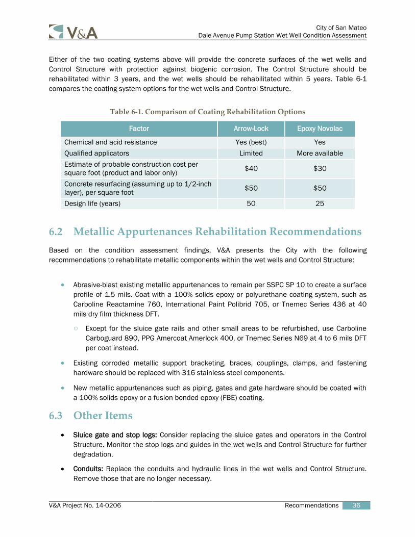
Either of the two coating systems above will provide the concrete surfaces of the wet wells and
Control Structure with protection against biogenic corrosion. The Control Structure should be
rehabilitated within 3 years, and the wet wells should be rehabilitated within 5 years. Table 6-1
compares the coating system options for the wet wells and Control Structure.
Table 6-1. Comparison of Coating Rehabilitation Options
Factor Arrow-Lock Epoxy Novolac
Chemical and acid resistance Yes (best) Yes
Qualified applicators Limited More available
Estimate of probable construction cost per
square foot (product and labor only) $40 $30
Concrete resurfacing (assuming up to 1/2-inch
layer), per square foot $50 $50
Design life (years) 50 25
6.2 Metallic Appurtenances Rehabilitation Recommendations
Based on the condition assessment findings, V&A presents the City with the following
recommendations to rehabilitate metallic components within the wet wells and Control Structure:
Abrasive-blast existing metallic appurtenances to remain per SSPC SP 10 to create a surface
profile of 1.5 mils. Coat with a 100% solids epoxy or polyurethane coating system, such as
Carboline Reactamine 760, International Paint Polibrid 705, or Tnemec Series 436 at 40
mils dry film thickness DFT.
○ Except for the sluice gate rails and other small areas to be refurbished, use Carboline
Carboguard 890, PPG Amercoat Amerlock 400, or Tnemec Series N69 at 4 to 6 mils DFT
per coat instead.
Existing corroded metallic support bracketing, braces, couplings, clamps, and fastening
hardware should be replaced with 316 stainless steel components.
New metallic appurtenances such as piping, gates and gate hardware should be coated with
a 100% solids epoxy or a fusion bonded epoxy (FBE) coating.
6.3 Other Items
Sluice gate and stop logs: Consider replacing the sluice gates and operators in the Control
Structure. Monitor the stop logs and guides in the wet wells and Control Structure for further
degradation.
Conduits: Replace the conduits and hydraulic lines in the wet wells and Control Structure.
Remove those that are no longer necessary.

City of San Mateo
Dale Avenue Pump Station Wet Well Condition Assessment
V&A Project No. 14-0206 Recommendations 37
Ducting and miscellaneous pipes: Monitor the FRP ducts in the wet wells for further
degradation. Replace the corroded pipe penetrations inside Wet Well 2 or abandon them if
they are no longer used. Coat the inside of the air jumpers from the Control Structure along
with recoating the concrete walls.
Railings: Repair or replace the railings on the platforms in the wet wells to address the issues
noted earlier in this report. Consider adding chains or other devices to close off the opening
at the east end of each railing.
Access: Consider ways to improve access to the wet wells.

V&A Project No. 14-0206 Appendix A. Paint Sample Analytical Report 1
APPENDIX A. PAINT SAMPLE ANALYTICAL
REPORT

Analytical Report 495758for
V & A Consulting Engineers Inc.
Project Manager: Noy Phannavong
Dale Ave. PS Wet Well Evaluation
30-OCT-14
14-0206
4143 Greenbriar Dr., Stafford, TX 77477
Xenco-Houston (EPA Lab code: TX00122):Texas (T104704215-14-18), Arizona (AZ0765), Florida (E871002), Louisiana (03054)New Jersey (TX007), North Carolina(681), Oklahoma (9218), Pennsylvania (68-03610)
Xenco-Atlanta (EPA Lab Code: GA00046):Florida (E87429), North Carolina (483), South Carolina (98015), Kentucky (85), DoD ( L10-135)
Texas (T104704477), Louisiana (04176), USDA (P330-07-00105)
Xenco-Lakeland: Florida (E84098)Xenco-Odessa (EPA Lab code: TX00158): Texas (T104704400-TX)Xenco-Dallas (EPA Lab code: TX01468): Texas (T104704295-TX)
Xenco Phoenix (EPA Lab Code: AZ00901): Arizona(AZ0757)Xenco-Phoenix Mobile (EPA Lab code: AZ00901): Arizona (AZM757)
Xenco Tucson (EPA Lab code:AZ000989): Arizona (AZ0758)
Collected By: Client
Page 1 of 15 Final 1.000

Houston - Dallas - Odessa - San Antonio - Tampa - Lakeland - Atlanta - Phoenix - Oklahoma - Latin America
Recipient of the Prestigious Small Business Administration Award of Excellence in 1994.Certified and approved by numerous States and Agencies.
A Small Business and Minority Status Company that delivers SERVICE and QUALITY
Project Manager: Noy Phannavong V & A Consulting Engineers Inc.155 Grand Ave, Suite 700Oakland, CA 94612 Reference: XENCO Report No(s): 495758 Dale Ave. PS Wet Well Evaluation Project Address: San Mateo Dale Ave. PS
Noy Phannavong:
We are reporting to you the results of the analyses performed on the samples received under the project namereferenced above and identified with the XENCO Report Number(s) 495758. All results being reported underthis Report Number apply to the samples analyzed and properly identified with a Laboratory ID number.Subcontracted analyses are identified in this report with either the NELAC certification number of thesubcontract lab in the analyst ID field, or the complete subcontracted report attached to this report.
Unless otherwise noted in a Case Narrative, all data reported in this Analytical Report are in compliance withNELAC standards. The uncertainty of measurement associated with the results of analysis reported isavailable upon request. Should insufficient sample be provided to the laboratory to meet the method andNELAC Matrix Duplicate and Matrix Spike requirements, then the data will be analyzed, evaluated andreported using all other available quality control measures.
The validity and integrity of this report will remain intact as long as it is accompanied by this letter andreproduced in full, unless written approval is granted by XENCO Laboratories. This report will be filed for atleast 5 years in our archives after which time it will be destroyed without further notice, unless otherwisearranged with you. The samples received, and described as recorded in Report No. 495758 will be filed for60 days, and after that time they will be properly disposed without further notice, unless otherwise arrangedwith you. We reserve the right to return to you any unused samples, extracts or solutions related to them if weconsider so necessary (e.g., samples identified as hazardous waste, sample sizes exceeding analytical standardpractices, controlled substances under regulated protocols, etc).
We thank you for selecting XENCO Laboratories to serve your analytical needs. If you have any questionsconcerning this report, please feel free to contact us at any time.
Respectfully,
30-OCT-14
Project ManagerDebbie Simmons
Page 2 of 15 Final 1.000

Sample Cross Reference 495758
V & A Consulting Engineers Inc., Oakland, CADale Ave. PS Wet Well Evaluation
Sample Id
DAPS Wet Well 1DAPS Wet Well 2
10-20-14 00:0009-30-14 00:00
Date Collected Lab Sample Id
495758-001495758-002
Sample DepthMatrix
SS
Page 3 of 15 Final 1.000

CASE NARRATIVE
495758Work Order Number(s):30-OCT-14Report Date: 14-0206Project ID:
Project Name: Dale Ave. PS Wet Well Evaluation
Date Received:
Client Name: V & A Consulting Engineers Inc.
10/23/2014
None
LBA-953853Batch: MS and MSD recovered below the QC limits. Matrix Interference is suspected.
Total Metals by EPA 6010B
Sample receipt non conformances and comments:
Sample receipt non conformances and comments per sample:
Analytical non conformances and comments:
Page 4 of 15 Final 1.000

14-0206Project Id:
V & A Consulting Engineers Inc., Oakland, CA
Noy PhannavongContact:San Mateo Dale Ave. PSProject Location:
Thu Oct-23-14 09:30 am 30-OCT-14Debbie Simmons
Date Received in Lab:Report Date:
Project Manager:
Project Name: Dale Ave. PS Wet Well Evaluation
This analytical report, and the entire data package it represents, has been made for your exclusive and confidential use.The interpretations and results expressed throughout this analytical report represent the best judgment of XENCO Laboratories.XENCO Laboratories assumes no responsibility and makes no warranty to the end use of the data hereby presented.Our liability is limited to the amount invoiced for this work order unless otherwise agreed to in writing.
Houston - Dallas - San Antonio - Atlanta - Tampa - Boca Raton - Latin America - Odessa - Corpus Christi________________________________
Project ManagerDebbie Simmons
Certificate of Analysis Summary 495758
Mercury by SW-846 7471A
Total Metals by EPA 6010B
Oct-29-14 12:47
Oct-25-14 06:57
Oct-29-14 12:49
Oct-25-14 04:20
mg/kg
mg/kg
Units/RL:
Units/RL:
mg/kg
mg/kg
Oct-29-14 10:30
Oct-24-14 10:00
Extracted:
Extracted:
Oct-29-14 10:30
Oct-24-14 10:00
Analysis Requested
495758-001Lab Id:
Field Id: DAPS Wet Well 1
SCRAPINGS
Oct-20-14 00:00
Depth:
Matrix:
Sampled:
0.0697
BRLBRL169 BRLBRL3.34 BRL2.52 1.95 1.97 28.4 BRLBRLBRL2.52 4.93
0.0182
1.92 1.92 0.962
0.385
0.962
0.962
0.962
1.92 1.92 0.962
0.962
2.88 1.92 1.92 1.92 2.88
Mercury
Antimony Arsenic Barium Beryllium Cadmium Chromium Cobalt Copper Lead Molybdenum Nickel Selenium Silver Thallium Vanadium Zinc
0.171 K
BRLBRL195
0.451
BRLBRLBRL2.81 3.05 BRLBRLBRLBRLBRL3.69 3.18
0.0185
1.96 1.96 0.980
0.392
0.980
0.980
0.980
1.96 1.96 0.980
0.980
2.94 1.96 1.96 1.96 2.94
495758-002
DAPS Wet Well 2
SCRAPINGS
Sep-30-14 00:00
RL
RL
RL
RL
Analyzed:
Analyzed:
Page 5 of 15 Final 1.000

XENCO LaboratoriesCHRONOLOGY OF HOLDING TIMES
DAPS Wet Well 1
DAPS Wet Well 2
Field Sample ID
Oct. 20, 2014Sep. 30, 2014
Date Collected
180180
MaxHolding Time
Extracted(Days)
Oct.25, 2014Oct.25, 2014
Date Analyzed
14-0206Project ID:
Oct. 23, 2014Oct. 23, 2014
Date Received
424
TimeHeld
Extracted
(Days
180180
MaxHolding
TimeAnalyzed
(Days)
11
TimeHeld
Analyzed(Days)
PP
Q
Oct. 24, 2014Oct. 24, 2014
Date Extracted
Client :Analytical Method : Total Metals by EPA 6010B
Work Order #: 495758V & A Consulting Engineers Inc.
Page 6 of 15 Final 1.000

XENCO LaboratoriesCHRONOLOGY OF HOLDING TIMES
DAPS Wet Well 2
DAPS Wet Well 1
Field Sample ID
Sep. 30, 2014Oct. 20, 2014
Date Collected
2828
MaxHolding Time
Extracted(Days)
Oct.29, 2014Oct.29, 2014
Date Analyzed
14-0206Project ID:
Oct. 23, 2014Oct. 23, 2014
Date Received
299
TimeHeld
Extracted
(Days
2828
MaxHolding
TimeAnalyzed
(Days)
00
TimeHeld
Analyzed(Days)
FP
Q
Oct. 29, 2014Oct. 29, 2014
Date Extracted
Client :Analytical Method : Mercury by SW-846 7471A
Work Order #: 495758V & A Consulting Engineers Inc.
F = These samples were analyzed outside the recommended holding time.P = Samples analyzed within the recommended holding time.
Page 7 of 15 Final 1.000

Houston - Dallas - San Antonio - Atlanta - Midland/Odessa - Tampa/Lakeland - Phoenix - Latin America
4143 Greenbriar Dr, Stafford, TX 774779701 Harry Hines Blvd , Dallas, TX 75220 5332 Blackberry Drive, San Antonio TX 78238 2505 North Falkenburg Rd, Tampa, FL 3361912600 West I-20 East, Odessa, TX 797656017 Financial Drive, Norcross, GA 300713725 E. Atlanta Ave, Phoenix, AZ 85040
Phone Fax(281) 240-4200 (281) 240-4280(214) 902 0300 (214) 351-9139(210) 509-3334 (210) 509-3335(813) 620-2000 (813) 620-2033(432) 563-1800 (432) 563-1713(770) 449-8800 (770) 449-5477(602) 437-0330
Recipient of the Prestigious Small Business Administration Award of Excellence in 1994.Certified and approved by numerous States and Agencies.
A Small Business and Minority Status Company that delivers SERVICE and QUALITY
Flagging Criteria
X In our quality control review of the data a QC deficiency was observed and flagged as noted. MS/MSD recoveries were found to be outside of the laboratory control limits due to possible matrix /chemical interference, or a concentration of target analyte high enough to affect the recovery of the spike concentration. This condition could also affect the relative percent difference in the MS/MSD.
B A target analyte or common laboratory contaminant was identified in the method blank. Its presence indicates possible field or laboratory contamination.
D The sample(s) were diluted due to targets detected over the highest point of the calibration curve, or due to matrix interference. Dilution factors are included in the final results. The result is from a diluted sample.
E The data exceeds the upper calibration limit; therefore, the concentration is reported as estimated.
F RPD exceeded lab control limits.
J The target analyte was positively identified below the quantitation limit and above the detection limit.
U Analyte was not detected.
L The LCS data for this analytical batch was reported below the laboratory control limits for this analyte. The department supervisor and QA Director reviewed data. The samples were either reanalyzed or flagged as estimated concentrations.
H The LCS data for this analytical batch was reported above the laboratory control limits. Supporting QC Data were reviewed by the Department Supervisor and QA Director. Data were determined to be valid for reporting.
K Sample analyzed outside of recommended hold time.
JN A combination of the "N" and the "J" qualifier. The analysis indicates that the analyte is "tentatively identified" and the associated numerical value may not be consistent with the amount actually present in the environmental sample.
** Surrogate recovered outside laboratory control limit.
BRL Below Reporting Limit.
RL Reporting Limit
MDL Method Detection Limit SDL Sample Detection Limit LOD Limit of Detection
PQL Practical Quantitation Limit MQL Method Quantitation Limit LOQ Limit of Quantitation
DL Method Detection Limit
NC Non-Calculable
+ NELAC certification not offered for this compound. * (Next to analyte name or method description) = Outside XENCO's scope of NELAC accreditation
Page 8 of 15 Final 1.000

BS / BSD Recoveries
495758 14-0206
Dale Ave. PS Wet Well EvaluationProject Name:
Project ID:
Relative Percent Difference RPD = 200*|(C-F)/(C+F)|Blank Spike Recovery [D] = 100*(C)/[B]Blank Spike Duplicate Recovery [G] = 100*(F)/[E]All results are based on MDL and Validated for QC Purposes
Work Order #:
Mercury by SW-846 7471A
Mercury <0.0200 0.200 98 2 2080-120
SpikeAdded
[B]
96
BlankSpike%R[D]
RPD%
ControlLimits%RPD
FlagControlLimits %R
BlankSpike
Result[C]
Blk. Spk Dup.%R[G]
BlankSpike
DuplicateResult [F]
0.192 0.195
954156Lab Batch ID: Matrix: Solid
BLANK /BLANK SPIKE / BLANK SPIKE DUPLICATE RECOVERY STUDYmg/kgUnits:
663677-1-BKSSample: 1Batch #:
0.200
SpikeAdded
[E]
Blank Sample Result
[A]
Analytes
ANSAnalyst: Date Analyzed: 10/29/201410/29/2014Date Prepared:
Page 9 of 15 Final 1.000

BS / BSD Recoveries
495758 14-0206
Dale Ave. PS Wet Well EvaluationProject Name:
Project ID:
Relative Percent Difference RPD = 200*|(C-F)/(C+F)|Blank Spike Recovery [D] = 100*(C)/[B]Blank Spike Duplicate Recovery [G] = 100*(F)/[E]All results are based on MDL and Validated for QC Purposes
Work Order #:
Total Metals by EPA 6010B
Antimony
Arsenic
Barium
Beryllium
Cadmium
Chromium
Cobalt
Copper
Lead
Molybdenum
Nickel
Selenium
Silver
Thallium
Vanadium
Zinc
<2.00
<2.00
<1.00
<0.400
<1.00
<1.00
<1.00
<2.00
<2.00
<1.00
<1.00
<3.00
<2.00
<2.00
<2.00
<3.00
100
100
100
100
100
100
100
100
100
100
100
100
50.0
100
100
100
103
103
102
103
101
107
103
103
105
102
103
106
96
107
100
102
1
1
1
1
2
1
2
1
2
2
2
2
3
2
1
2
20
20
20
20
20
20
20
20
20
20
20
20
20
20
20
20
80-120
80-120
80-120
80-120
80-120
80-120
80-120
80-120
80-120
80-120
80-120
80-120
80-120
80-120
80-120
80-120
SpikeAdded
[B]
104
104
103
104
103
108
105
104
107
104
105
108
93
109
99
104
BlankSpike%R[D]
RPD%
ControlLimits%RPD
FlagControlLimits %R
BlankSpike
Result[C]
Blk. Spk Dup.%R[G]
BlankSpike
DuplicateResult [F]
104
104
103
104
103
108
105
104
107
104
105
108
46.3
109
99.4
104
103
103
102
103
101
107
103
103
105
102
103
106
47.8
107
100
102
953853Lab Batch ID: Matrix: Solid
BLANK /BLANK SPIKE / BLANK SPIKE DUPLICATE RECOVERY STUDYmg/kgUnits:
663433-1-BKSSample: 1Batch #:
100
100
100
100
100
100
100
100
100
100
100
100
50.0
100
100
100
SpikeAdded
[E]
Blank Sample Result
[A]
Analytes
DABAnalyst: Date Analyzed: 10/25/201410/24/2014Date Prepared:
Page 10 of 15 Final 1.000

Form 3 - MS / MSD Recoveries
Matrix Spike Percent Recovery [D] = 100*(C-A)/B Matrix Spike Duplicate Percent Recovery [G] = 100*(F-A)/ERelative Percent Difference RPD = 200*|(C-F)/(C+F)|
ND = Not Detected, J = Present Below Reporting Limit, B = Present in Blank, NR = Not Requested, I = Interference, NA = Not ApplicableN = See Narrative, EQL = Estimated Quantitation Limit, NC = Non Calculable - Sample amount is > 4 times the amount spiked.
495758 14-0206
Dale Ave. PS Wet Well EvaluationProject Name:
Project ID:Work Order # :
Mercury <0.0224 0.224 93 0 2075-125
SpikeAdded
[B]
SpikedSample
%R[D]
RPD%
ControlLimits%RPD
ControlLimits %R
Spiked SampleResult
[C]
SpikedDup.%R[G]
DuplicateSpiked Sample
Result [F]
920.207 0.208
Mercury by SW-846 7471A
495627-001 SQC- Sample ID:Lab Batch ID: 954156 Matrix: Soil
MATRIX SPIKE / MATRIX SPIKE DUPLICATE RECOVERY STUDYmg/kgReporting Units:
0.224
SpikeAdded
[E]
ParentSampleResult
[A]
Flag
Analytes
1Batch #:ANSAnalyst:Date Analyzed: 10/29/2014 10/29/2014Date Prepared:
Page 11 of 15 Final 1.000

Form 3 - MS / MSD Recoveries
Matrix Spike Percent Recovery [D] = 100*(C-A)/B Matrix Spike Duplicate Percent Recovery [G] = 100*(F-A)/ERelative Percent Difference RPD = 200*|(C-F)/(C+F)|
ND = Not Detected, J = Present Below Reporting Limit, B = Present in Blank, NR = Not Requested, I = Interference, NA = Not ApplicableN = See Narrative, EQL = Estimated Quantitation Limit, NC = Non Calculable - Sample amount is > 4 times the amount spiked.
495758 14-0206
Dale Ave. PS Wet Well EvaluationProject Name:
Project ID:Work Order # :
Antimony
Arsenic
Barium
Beryllium
Cadmium
Chromium
Cobalt
Copper
Lead
Molybdenum
Nickel
Selenium
Silver
Thallium
Vanadium
Zinc
55.1
7230
143
0.452
125
<1.00
4.15
574
20700
10.4
<1.00
86.6
79.7
<2.00
10.6
4520
100
100
100
100
100
100
100
100
100
100
100
100
50.0
100
100
100
63
0
63
68
69
44
69
84
0
65
67
68
61
67
65
0
17
14
13
15
14
13
15
15
14
15
14
14
16
14
15
6
20
20
20
20
20
20
20
20
20
20
20
20
20
20
20
20
X
X
X
X
X
X
X
X
X
X
X
X
X
X
X
X
75-125
75-125
75-125
75-125
75-125
75-125
75-125
75-125
75-125
75-125
75-125
75-125
75-125
75-125
75-125
75-125
SpikeAdded
[B]
SpikedSample
%R[D]
RPD%
ControlLimits%RPD
ControlLimits %R
Spiked SampleResult
[C]
SpikedDup.%R[G]
DuplicateSpiked Sample
Result [F]
45
0
37
58
43
38
59
0
0
55
58
48
28
58
54
0
99.7
6230
180
58.8
168
38.2
62.7
568
17900
65.3
57.7
135
93.6
58.1
65.0
4230
118
7160
206
68.3
194
43.6
72.8
658
20500
75.6
66.5
155
110
67.1
75.8
4480
Total Metals by EPA 6010B
495770-001 SQC- Sample ID:Lab Batch ID: 953853 Matrix: Soil
MATRIX SPIKE / MATRIX SPIKE DUPLICATE RECOVERY STUDYmg/kgReporting Units:
100
100
100
100
100
100
100
100
100
100
100
100
50.0
100
100
100
SpikeAdded
[E]
ParentSampleResult
[A]
Flag
Analytes
1Batch #:DABAnalyst:Date Analyzed: 10/25/2014 10/24/2014Date Prepared:
Page 12 of 15 Final 1.000

Page 13 of 15 Final 1.000

Page 14 of 15 Final 1.000

Prelogin/Nonconformance Report- Sample Log-InXENCO Laboratories
495758Work Order #:
10/23/2014 09:30:00 AMDate/ Time Received:
V & A Consulting Engineers Inc. Client:
Sample Receipt Checklist
Checklist completed by: Date:
Checklist reviewed by:Date:
Debbie Simmons
10/23/2014
10/23/2014
#2 *Shipping container in good condition? #3 *Samples received on ice? #4 *Custody Seals intact on shipping container/ cooler? #5 Custody Seals intact on sample bottles? #6 *Custody Seals Signed and dated? #7 *Chain of Custody present? #8 Sample instructions complete on Chain of Custody? #9 Any missing/extra samples? #10 Chain of Custody signed when relinquished/ received? #11 Chain of Custody agrees with sample label(s)? #12 Container label(s) legible and intact? #13 Sample matrix/ properties agree with Chain of Custody? #14 Samples in proper container/ bottle? #15 Samples properly preserved? #16 Sample container(s) intact? #17 Sufficient sample amount for indicated test(s)? #18 All samples received within hold time? #19 Subcontract of sample(s)? #20 VOC samples have zero headspace (less than 1/4 inch bubble)? #21 <2 for all samples preserved with HNO3,HCL, H2SO4? Except forsamples for the analysis of HEM or HEM-SGT which are verified by theanalysts. #22 >10 for all samples preserved with NaAsO2+NaOH, ZnAc+NaOH?
YesNoNoNoNoYesYesNoYesYesYesYesYesYesYesYesYesN/AN/AN/A
N/A
#1 *Temperature of cooler(s)? 20
Acceptable Temperature Range: 0 - 6 degCAir and Metal samples Acceptable Range: Ambient
* Must be completed for after-hours delivery of samples prior to placing in the refrigerator
Analyst: PH Device/Lot#:th
Comments
Tanya Torres
Temperature Measuring device used :
Page 15 of 15 Final 1.000


![[XLS]KDCB Music Library - Home | SESD Music Department · Web viewZoot Suit Riot Perry, Steve Kennard-Dale Kennard-Dale Kennard-Dale Kennard-Dale Kennard-Dale Kennard-Dale Kennard-Dale](https://static.fdocuments.net/doc/165x107/5b1a7c437f8b9a28258d8e9a/xlskdcb-music-library-home-sesd-music-web-viewzoot-suit-riot-perry-steve.jpg)