The Manager's Pocket Guide to Workplace Coaching (Manager's Pocket Guide Series)
Upload
dean-huffordCategory
view
895download
53
TO 31R4-2PSN13-8-1TB 11-5820-1172-10
EE174-AD-OPI-010/NAVAIR 16-30PSN13-216-PSN13-2
PCN 18409880300 / TM 09880C-OR
OPERATOR’S GUIDE
DAGR OPERATOR’S POCKET GUIDE
DISCLOSURE NOTICE: This information is furnished upon thecondition that it will not be released to another nation without thespecific authority of the Department of the Air Force of the UnitedStates, that it will be used for military purpose only, that individualor corporate rights originating in the information, whether patentedor not, will be respected, that the recipient will report promptly tothe United States, any known or suspected compromise, and thatthe information will be provided substantially the same degree ofsecurity afforded it by the Department of Defense of the UnitedStates. Also, regardless of any other markings on the document, itwill not be downgraded or declassified without written approval ofthe originating United States agency.
NOTICE: Rights as defined by DFARS 252.227–7013 are limitedexcept for installation, operation, maintenance, or training purposes(other than detailed manufacturing process data) whereby unlimitedrights are provided.
STATEMENT D, DoD & Contractors, 570 CBSS/GBENS RobinsAFB, GA 31098.
HANDLING AND DESTRUCTION NOTICE: Destroy by anymethod that will prevent disclosure of contents or reconstruction ofthe document.
PUBLISHED UNDER AUTHORITY OF THE SECRETARIES OF THE AIR FORCE,ARMY, MARINE CORPS, AND NAVY
1 March 2005 Change 2 1 October 2006

TO 31R4-2PSN-13-8-1 TB 11-5820-1172-10 EE 174-AD-OPI-010/NAVAIR 16-30PSN13-2 16-PSN13-2 PCN 18409880300/TM 09880C-OR C2 Change HEADQUARTERS, DEPARTMENTS OF THE AIR FORCE, ARMY, NAVY, AND COMMANDANT, MARINE CORPS No. 2 Washington, DC, 1 October 2006
Operator and Maintenance Manual for
DEFENSE ADVANCED GPS RECEIVER (DAGR) SATELLITE SIGNALS NAVIGATION SET
AN/PSN-13 (NSN 5825-01-516-8038)
AN/PSN-13A (NSN 5825-01-526-4783)
TO 31R4-2PSN8-1; TB 11-5820-1172-10; EE 174-AD-OPI-010/NAVAIR 16-30PSN13-2, 16-PSN-13-2; PCN 18409880300/TM 09880C-OR, dated 1 March 2005, is changed as follows: 1. Title of the manual has been changed as shown above. 2. Remove old pages and insert new pages as indicated below. New or changed material is indicated by a vertical bar in the margin of the following pages: 3. File this change sheet in front of the publication for reference purposes.
Distribution authorized to the Department of Defense and DOD contractors only for official use or for administrative purposes only. This determination was made on 31 December 2002. Other requests for this document must be referred to Commander, US Army Communications Electronics Command and Fort Monmouth, ATTN: AMSEL-LC-LEO-E-ED-P, Fort Monmouth, New Jersey, 07703-5006. DESTRUCTION NOTICE – Destroy by any method that will prevent disclosure of contents or reconstruction of the document.

Remove Pages Insert Pages Cover and A Cover and A V and vi v and vi Vii and viii vii and viii ix/(x blank) ix(x blank) 4-1 through 4-4 4-1 through 4-4 9-1 through 9-3/(9-4 blank) 9-1 through 9-3/(9-4 blank) 11-1 through 11-19/(11-20 blank) 11-1 through 11-19/(11-20 blank) 12-3 and 12-4 12-3 and 12-4 13-1 through 13-4 13-1 through 13-4 14-3 and 14-4 14-3 and 14-4
By Order of the Secretaries of the Air Force, Army, and Navy (Including the Marine Corps): Official: BRUCE CARLSON General, USAF T. MICHAEL MOSLEY General, USAF Commander, Air Force Materiel Command Chief of Staff Official: JOYCE E. MORROW PETER J. SCHOOMAKER General, USA Administrative Assistant Chief of Staff to the Secretary of the Army 0630301 Official: J. D. WILSON MICHAEL W. HAGEE General, USMC Program Manager Communications Systems Commandant of the Marine Corps Marine Corps Systems Command Official: DENNIS M. BAUMAN VERN CLARK Admiral, USN Program Executive Officer Chief of Naval Operations Command, Control, Communications, Computers Intelligence and Space
.

TO 31R4-2PSN-13-8-1 TB 11-5820-1172-10 EE 174-AD-OPI-010 16-PSN13-1 PCN 18409880300/TM 09880C-OR C1 Change HEADQUARTERS, DEPARTMENTS OF THE AIR FORCE, ARMY, NAVY, AND COMMANDANT, MARINE CORPS No. 1 Washington, DC, 1 June 2005
Operator’s Pocket Guide for
DEFENSE ADVANCED GPS RECEIVER (DAGR) SATELLITE SIGNALS NAVIGATION SET
AN/PSN-13 (NSN 5825-01-516-8038)
AN/PSN-13A (NSN 5825-01-526-4783)
TO 31R4-2PSN13-8-1; TB 11-5820-1172-10; EE 174-AD-OPI-010, 16-PSN-13-2; PCN 18409880300/TM 09880C-OR, dated 1 March 2005, is changed as follows: 1. Title of the manual has been changed as shown above. 2. Remove old pages and insert new pages as indicated below. New or changed material is indicated by a vertical bar in the margin of the following pages: 3. File this change sheet in front of the publication for reference purposes.
Distribution authorized to the Department of Defense and DOD contractors only for official use or for administrative purposes only. This determination was made on 31 December 2002. Other requests for this document must be referred to Commander, US Army Communications Electronics Command and Fort Monmouth, ATTN: AMSEL-LC-LEO-E-ED-P, Fort Monmouth, New Jersey, 07703-5006. DESTRUCTION NOTICE – Destroy by any method that will prevent disclosure of contents or reconstruction of the document.

Remove Pages Insert Pages Cover and A Cover and A I through Viii I through viii 1-1 through 1-3(1-4 blank) 1-1 through 1-3(1-4 blank) 2-1 through 2-10 2-1 through 2-10 3-1 through 3-7(3-8 blank) 3-1 through 3-7(3-8 blank) 4-1 through 4-4 4-1 through 4-4 5-1 through 5-3(5-4 blank) 5-1 through 5-3(blank) 6-1 through 6-4 6-1 through 6-4 7-1 through 7-8 7-1 through 7-8 8-1 through 8-23(8-24 blank) 8-1 through 8-23(8-24 blank) 9-1 through 9-3(9-4 blank) 9-1 through 9-3(9-4 blank) 10-1 through 10-6 10-1 through 10-6 11-1 through 11-18 11-1 through 11-18
By Order of the Secretaries of the Air Force, Army, and Navy (Including the Marine Corps): Official: GEORGE T. BABBETT General, USAF MICHAEL E. RYAN General, USAF Commander, Air Force Materiel Command Chief of Staff Official: SANDRA R. RILEY PETER J. SCHOOMAKER General, USA Administrative Assistant Chief of Staff to the Secretary of the Army 0411904 Official: J. D. WILSON MICHAEL W. HAGEE General, USMC Program Manager Communications Systems Commandant of the Marine Corps Marine Corps Systems Command Official: DENNIS M. BAUMAN VERN CLARK Admiral, USN Program Executive Officer Chief of Naval Operations Command, Control, Communications, Computers Intelligence and Space

TO 31R4-2PSN13-8-1
NOTE: The portion of the text affected by the changes is indicated by a vertical line in the outer margin of the page. Changes to illustrations are indicated by shaded or screened areas or by miniature pointing hands.
Dates of issue for original and change pages are:
Original .........................................0......................................... 1 March 2005 Change .........................................1........................................... 1 June 2005 Change .........................................2...................................... 1 October 2006 TOTAL NUMBER OF PAGES IN THIS PUBLICATION IS 114, CONSISTING OF THE FOLLOWING:
Page No. *Change No.
Title........................................2 A .............................................2 i thru iv ..................................0 v thru ix .................................2 x Blank...................................2 1-1 thru 1-3............................0 1-4 Blank ...............................0 2-1 thru 2-10..........................0 3-1 thru 3-7............................0 3-8 Blank ...............................0 4-1...........................................0 4-2 thru 4-3............................2 4-4...........................................0 5-1 thru 5-3............................0 5-4 Blank ...............................0 6-1 thru 6-4............................0
Page No. *Change No. 7-1 thru 7-6................................. 0 8-1 thru 8-23............................... 0 8-24 Blank .................................. 0 9-1................................................ 0 9-2 thru 9-3................................. 2 9-4 Blank .................................... 0 10-1 thru 10-5............................. 0 10-6.............................................. 2 11-1 thru 11-19........................... 2 11-20 Blank ................................ 2 12-1 thru 12-3............................. 0 12-4.............................................. 2 13-1 thru 13-4............................. 2 13-5 thru 13-6............................. 0 14-1 thru 14-3............................. 0 14-4.............................................. 2
LIST OF EFFECTIVE PAGES
*Zero in this column indicates an original page
INSERT LATEST CHANGED PAGES. DESTROY SUPERSEDED PAGES.
A Change 2

TO 31R4-2PSN13-8-1
TABLE OF CONTENTSChapter Page
FOREWORD .......................................................... v
1 DAGR PHYSICAL FEATURES ......................... 1-11.1 General ..................................................... 1-1
2 OPERATING PROCEDURES ............................ 2-12.1 Power-On ................................................. 2-12.2 Power-On and Commanded
Self-Test ................................................... 2-32.3 Mode of Operation ................................... 2-72.4 Power Off ............................................... 2-10
3 RECEIVER SETUP ............................................. 3-13.1 Manual Initialization ................................ 3-1
4 ACQUIRE CURRENT POSITION ..................... 4-14.1 Acquire Current Position ......................... 4-14.2 POS Page Set ........................................... 4-14.2.1 Present Position Page ............................... 4-24.2.2 Situational Awareness Page ..................... 4-24.2.3 NAV Pointer Page .................................... 4-34.2.4 Image Viewer Page .................................. 4-34.2.5 SV Sky View Page ................................... 4-4
i

TO 31R4-2PSN13-8-1
Chapter Page
5 WAYPOINTS ....................................................... 5-15.1 Waypoint Operation ................................. 5-15.2 Mark Present Position Waypoint ............. 5-15.3 Create A New Waypoint .......................... 5-2
6 NAVIGATION ..................................................... 6-16.1 Navigation Operation ............................... 6-16.2 Waypoint GOTO Navigation ................... 6-16.3 Alerts ........................................................ 6-3
7 OPERATION CHECKS ...................................... 7-17.1 Operation Checks ..................................... 7-1
8 DATA TRANSFER .............................................. 8-18.1 DAGR to DAGR Data Transfer ............... 8-18.2 Crypto Key Entry Using KYK-13 ........... 8-58.3 Red Crypto Key Entry Using
AN/CYZ-10 ............................................. 8-78.4 Black Crypto Key Entry Using
AN/CYZ-10 ........................................... 8-108.4.1 Set Parameters on AN/CYZ-10 ............. 8-108.4.2 Load BKAUPD Tape into
KOI-18 ................................................... 8-128.4.3 Load Crypto Key Tape into
KOI-18 ................................................... 8-138.4.4 Set Up DAGR ........................................ 8-14
ii

TO 31R4-2PSN13-8-1
Chapter Page
8.4.5 Set Up AN/CYZ-10 ............................... 8-158.4.6 Load BKAUPD Key into DAGR .......... 8-178.4.7 Load Crypto Key into DAGR ................ 8-188.5 Data Clear .............................................. 8-198.6 Emergency Zeroize ................................ 8-218.7 Zeroize CV Keys ................................... 8-22
9 OPERATION UNDER UNUSUALCONDITIONS ..................................................... 9-19.1 Areas Blocking Signals ............................ 9-19.2 Electronic Warfare ................................... 9-29.2.1 Spoofing and Anti-Spoofing .................... 9-29.2.2 Jamming and Anti-Jamming .................... 9-2
10 TROUBLESHOOTING .................................... 10-110.1 Troubleshooting Procedure .................... 10-1
11 MESSAGES ...................................................... 11-111.1 Displayed Messages ............................... 11-1
12 BATTERY REPLACEMENT ........................... 12-112.1 Primary Battery Replacement ................ 12-112.2 Memory Battery Check .......................... 12-3
13 EXTERNAL INTERFACE ............................... 13-113.1 Installation To Host Platform ................. 13-113.2 Removal From Host Platform ................ 13-6
iii

TO 31R4-2PSN13-8-1
Chapter Page
14 MENU TREE ..................................................... 14-114.1 Main Menu and Submenus .................... 14-1
iv

TO 31R4-2PSN13-8-1
FOREWORD
SCOPE.This pocket guide is designed for field use, and coversbasic tasks necessary to use the DAGR in the Basicoperating mode only. The user is provided essential tasksin abbreviated format along with related graphics whereapplicable. For more detailed information (includingTO/TM references throughout manual and DAGRadvanced functions), the user should refer to the DAGROperator and Maintenance Technical Manual. Help textcan be accessed when shown on the display. Equipmentcovered by this manual includes the AN/PSN-13 withsoftware 984-2461-012, and the AN/PSN-13A withsoftware 984-3006-002.
Questions concerning technical content should be directedto WR-ALC/GBENS.
GPS OPERATION.The NAVSTAR Global Positioning System (GPS) is aspace-based navigation and timing system made up ofmultiple satellites, a ground control system, and anynumber of navigation sets. The DAGR collects and
vChange 2

TO 31R4-2PSN13-8-1
processes satellite signals to provide position, velocity,and time (PVT) information, along with position reportingand navigation capabilities.
SAFETY SUMMARY.
• To prevent injury or death during spoofingor jamming, the DAGR must be loaded withcurrent CV keys to operate correctly and im-prove accuracy.• If abused, lithium batteries can explode causingsevere injury. Be sure to store batteries in originalpackaging until ready to use and observe polarityduring installation. Reverse polarity can causedamage to the battery and receiver.• To prevent electrical shock, never open the ex-ternal 110 V AC power cable adapter and nevercome in contact with its AC plug during opera-tion.• DAGR displays a warning when powered on af-ter previously using the Fire Support page or afternonvolatile memory is cleared, stating the presentposition displayed is NOT the target position ofthe Fire Support page.
vi Change 2

TO 31R4-2PSN13-8-1
SAFETY SUMMARY (CONT).
• All batteries in extreme temperatures havereduced capabilities. In the desert, DAGR ra-diant internal temperature could exceed 200 °F.Lithium batteries breakdown at 260 °F, alkalinebatteries breakdown at 200 °F, and both can puttoxic fumes into the air. When batteries break-down, the DAGR battery connections can alsobecome corroded. Wash any acid away fromskin with running water. Lithium batteries arerecommended for use in extreme temperatures.• Do not mix new batteries with old batteries. Donot mix battery types. Do not reverse battery po-larity. Use only fresh/new batteries. This ensuresproper battery life and proper unit operation.• Ensure a good memory battery is installed be-fore removing the primary battery pack to ensureall settings in memory are retained. A good mem-ory battery is indicated by checking the memorybattery date on the battery page, or if the battery islow, a Low Memory Battery message will showon the display.
Change 2 vii

TO 31R4-2PSN13-8-1
SAFETY SUMMARY (CONT).
• Failure to observe correct polarity when in-stalling the external DC power cable may resultin damage to the DAGR. If using an external DCpower source, ensure positive (red) lead of theexternal DC power cable is connected to positivelead of external power source. The DAGR isprotected against accidental reverse connectionof external power.• Current position is necessary before accuratenavigation of waypoints and routes can be accom-plished.• A high level of position error may place a mis-sion at risk. Verify the FOM level is sufficientto accomplish the mission. Refer to Present Posi-tion or NAV Displays pages for the current FOM.• Both the Zeroize function and Data Clear Op-tions function destroy mission critical data, andDAGR operation can become seriously impairedfor a particular mission without this data.
viii Change 2

TO 31R4-2PSN13-8-1
SAFETY SUMMARY (CONT).
• When position data fields blink between blackand gray text, the DAGR is not tracking satellitesor has not yet acquired present position. Fielddata may be inaccurate when the DAGR does nothave a position fix. Be sure the DAGR has anopen view of the sky to acquire the present posi-tion. If the position data fields continue to blink,perform the manual initialization procedure.• Accidental jamming may occur when operatingthe DAGR near a source of high power electronicemissions. Move away from these sources andverify operation.
ix/(x blank)Change 2


TO 31R4-2PSN13-8-1
CHAPTER 1DAGR PHYSICAL FEATURES
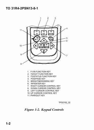
1.1 GENERAL.Refer to TO/TM paragraphs 4.4 and 2.2. Refer to Figure1-1 for display indicators, Figure 1-2 for keypad controls,and Figure 1-3 for physical features.
Figure 1-1. Display Indicators
1-1
TO 31R4-2PSN13-8-1
Figure 1-2. Keypad Controls
1-2

TO 31R4-2PSN13-8-1
Figure 1-3. Physical Features
1-3/(1-4 blank)

TO 31R4-2PSN13-8-1
CHAPTER 2OPERATING PROCEDURES
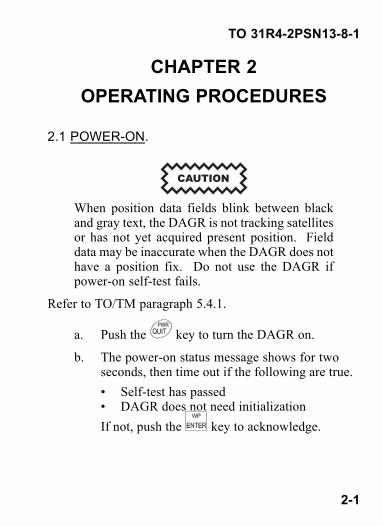
2.1 POWER-ON.
When position data fields blink between blackand gray text, the DAGR is not tracking satellitesor has not yet acquired present position. Fielddata may be inaccurate when the DAGR does nothave a position fix. Do not use the DAGR ifpower-on self-test fails.
Refer to TO/TM paragraph 5.4.1.
a. Push the key to turn the DAGR on.
b. The power-on status message shows for twoseconds, then time out if the following are true.• Self-test has passed• DAGR does not need initializationIf not, push the key to acknowledge.
2-1

TO 31R4-2PSN13-8-1
TPG1290_01
c. If a CV key, GUV key, or SV code conditionexists, acknowledge messages accordingly.
d. DAGR displays the SV Sky View page, thenautomatically switches to the Present Positionpage when current position is acquired.
TPG1236_01
e. If keypad/display lighting is required, togglelighting on and off by pushing and holding the
key.
2-2
TO 31R4-2PSN13-8-1
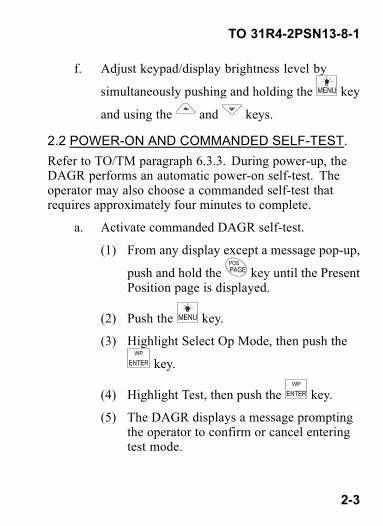
f. Adjust keypad/display brightness level by
simultaneously pushing and holding the key
and using the and keys.
2.2 POWER-ON AND COMMANDED SELF-TEST.Refer to TO/TM paragraph 6.3.3. During power-up, theDAGR performs an automatic power-on self-test. Theoperator may also choose a commanded self-test thatrequires approximately four minutes to complete.
a. Activate commanded DAGR self-test.
(1) From any display except a message pop-up,
push and hold the key until the PresentPosition page is displayed.
(2) Push the key.
(3) Highlight Select Op Mode, then push the
key.
(4) Highlight Test, then push the key.
(5) The DAGR displays a message promptingthe operator to confirm or cancel enteringtest mode.
2-3

TO 31R4-2PSN13-8-1
TPG1280_01
b. Push the key to confirm.
c. Test In Progress display appears with specificarea of testing listed at bottom and a bar graphdenoting progress. DAGR automaticallyprogresses to next test.
TPG1281_01
2-4

TO 31R4-2PSN13-8-1
NOTEWhile doing the following keypad test, push
and hold the key to test the key.
Push and release the key advances tothe next test.
d. Keypad Test is displayed. Push each key onthe keypad and verify the corresponding keyshown on the display toggles between normaland highlighted appearance. Push and release
the key to continue.
TPG1282_01
e. Display Light Test display appears with thebrightness adjustment cycling between 0% and100%. Verify the display lighting by viewing
the DAGR display in a dark area. Push thekey to continue.
2-5

TO 31R4-2PSN13-8-1
TPG1283_01
f. Contrast Test display appears with the contrastadjustment cycling between 0% and 100%. Push
the key to continue.
TPG1284_01
g. The Display Test Beginning message appearsmomentarily. The display sequences throughwhite, light gray, dark gray, and black shading.The Display Test Completed message appears,followed immediately by a Power-On Statusdisplay listing self-test results.
2-6

TO 31R4-2PSN13-8-1
TPG1285_01
TPG1290_01
h. Push the key to return to the SV Sky Viewpage.
NOTEThe DAGR automatically switches to theStandby mode of operation.
2.3 MODE OF OPERATION.Refer to TO/TM paragraph 6.2.23 for mode of operationdescriptions. Continuous is the normal operating mode forexternal power. Fix is the normal initial operating modewhen operating on battery power.
2-7

TO 31R4-2PSN13-8-1
• Continuous - Tracks satellites to produce a continuousPVT solution, and uses the most power.
• Fix - Tracks satellites to produce a current PVTsolution, then automatically transitions to Standbymode after a position fix is obtained.
• Standby - Operates at reduced power and does notacquire and track satellites, but performs all functionsthat do not require satellites.
• Other available modes - Average, Time Only,Rehearsal, Test, and Off.
Refer to TO/TM paragraphs 9.5 and 9.5.3 (procedure b).Perform the following procedure to select the operatingmode.
a. From any display except a message pop-up, push
and hold the key until the Present Positionpage is displayed.
b. Push the key.
c. Highlight Select Op Mode, then push thekey.
d. Highlight the desired operating mode, then push
the key.
2-8

TO 31R4-2PSN13-8-1
e. Display returns to the Present Position pagedisplaying the selected operation mode.
TPG0164_05
2-9
TO 31R4-2PSN13-8-1
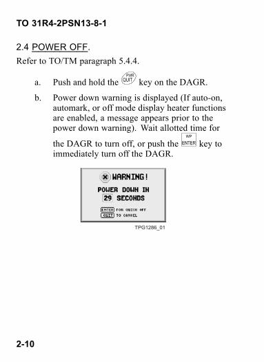
2.4 POWER OFF.Refer to TO/TM paragraph 5.4.4.
a. Push and hold the key on the DAGR.
b. Power down warning is displayed (If auto-on,automark, or off mode display heater functionsare enabled, a message appears prior to thepower down warning). Wait allotted time for
the DAGR to turn off, or push the key toimmediately turn off the DAGR.
TPG1286_01
2-10

TO 31R4-2PSN13-8-1
CHAPTER 3RECEIVER SETUP
3.1 MANUAL INITIALIZATION.
When data fields blink between black and graytext, the DAGR is not tracking satellites or ac-quired current position. Field data may be inac-curate when the DAGR does not have a positionfix.
Refer to TO/TM paragraph 5.4.2. If the DAGR has beenmoved between two different geographical locations andis not performing correctly, the DAGR may need to beinitialized according to the DAGRs current location. Thefollowing procedure describes how to initially set up theDAGR Present Position page fields and edit field contentwhen:• DAGR is having difficulty obtaining a position fix.• Datum is mismatched with navigation waypoints.• Datum does not match the geographical map used.
a. Power the DAGR on.
3-1

TO 31R4-2PSN13-8-1
b. Push and hold the key to access the PresentPosition page.
TPG0164_05
c. Select Datum.
(1) From the Present Position page, push the
key.
(2) Highlight Select Datum, then push thekey.
(3) Scroll using the and keys toselect the datum corresponding to thegeographical map being used, then push
the key.
(4) Display returns to the Present Position pagewith datum change made.
3-2

TO 31R4-2PSN13-8-1
d. Select Coordinate/Grid system.
(1) From the Present Position page, push the
key.
(2) Highlight Select Coord/Grid, then push the
key.
(3) Scroll using the and keys to selectthe coordinate/grid system correspondingto the geographical map being used, then
push the key.
(4) Display returns to the Present Position pagewith coordinate/grid system change made.
e. Select units of measure or references (asrequired).
(1) From the Present Position page, push the
key, then highlight the Elevation field,
then push the key.
(2) Highlight Select Elev Units, then push the
key.
3-3

TO 31R4-2PSN13-8-1
(3) Choose the appropriate unit of measure,
then push the key.
(4) Display returns to the Present Position pagewith change made.
(5) Edit Ground Speed and Track fields insimilar manner.
f. Configure initialization data (position, time,speed, and track).
NOTEEntering data may not be necessary if cur-rent almanac is available (Refer to TO/TMparagraph 13.2).
(1) From the Present Position page, push the
key, then use the , , , and
keys to scroll through and view fieldsas desired. If required, edit field contentto configure initialization data for currentgeographical location.
(2) When desired field is highlighted, push the
key. An editor appears.
3-4
TO 31R4-2PSN13-8-1
(3) For list editors, select the desired field
content and push the key. For text or
numeric editors, use the , , ,
and keys and standard alphanumeric
editor functions. Push the key to savenumeric changes, or select SAVE whenfinished with text changes.
(4) Display returns to the Present Position pagewith changes made to field content.
g. Select Continuous Operating Mode.
(1) From the Present Position page, push the
key.
(2) Highlight Select Op Mode, then push the
key.
(3) Highlight Continuous, then push thekey. If a message is displayed instructingthe operator that initialization is required,
push the key.
(4) Display returns to the Present Position pagewith operating mode change made.
3-5
TO 31R4-2PSN13-8-1
h. Observe Present Position page.
When attempting to acquire satellitesafter the signals have been blocked fora period of time (e.g., when exitinga cave), acquisition time may be im-proved bymomentarily cycling the unitto Standby mode and then back to theprevious operating mode.
(1) If Present Position page is not already
displayed, push and hold the key untilPresent Position page is obtained.
(2) The display position data fields stopblinking when the DAGR has obtained acurrent position fix. This current positiondata replaces any position data enteredmanually.
(3) DAGR is initialized with informationcorresponding to the current geographicallocation.
i. Observe SV Sky View page.
3-6

TO 31R4-2PSN13-8-1
(1) If Present Position page is not already
displayed, push and hold the key untilPresent Position page is obtained.
(2) Repeatedly push the key until SV SkyView page is obtained. Satellite acquisitioncan be monitored from this page.
3-7/(3-8 blank)

TO 31R4-2PSN13-8-1
CHAPTER 4ACQUIRE CURRENT POSITION
4.1 ACQUIRE CURRENT POSITION.Refer to TO/TM paragraph 5.4.1.3. The DAGR obtainscurrent position by simply turning the DAGR on with anopen view of the sky. While acquiring satellites, DAGRdisplays the SV Sky View page. After satellites areacquired, DAGR automatically transitions to the PresentPosition page with current position coordinates shown.An indication of when the DAGR has obtained currentposition is provided by:• Position data fields of the Present Position page remainsolid black text and do not blink.
• On the SV Sky View page, solid black horizontal barsindicate satellites being tracked and data is collected;and Navigating shows at the top of display.
4.2 POS PAGE SET.Refer to TO/TM paragraph 6.2.9. The POS page setcontains commonly used pages and are described as
follows. Use the key or key to scroll pages.
4-1

TO 31R4-2PSN13-8-1
4.2.1 Present Position Page. Displays present positioncoordinates, coordinate and grid system, datum identifier,current operating mode, estimated horizontal error, figureof merit, elevation, elevation reference, ground speed,track, estimated time error, time figure of merit, time anddate, MAGVAR, magnetic model year, and operator ID.Scroll the page vertically to view all field data.
TPG0164_05
4.2.2 Situational Awareness Page.
NOTERange circles are not shown on display when avector map is loaded into the DAGR.
Provides a graphical display of relationships betweenpresent position, track, waypoints, routes, alerts, andsearch grid. Includes a north reference indicator, groundspeed, track, position error data, and a range scale.
4-2 Change 2

TO 31R4-2PSN13-8-1
TPG1243_01
4.2.3 NAV Pointer Page. Displays a pointer directing theoperator towards the displayed waypoint. Also displayscurrent navigation method, destination waypoint numberand name, azimuth, and range information.
TPG1224_01
4.2.4 Image Viewer Page. Displays images or mapsincluding current position (center of display), landmarks,map objects, and selected waypoints, routes, and alerts.The operator uses zoom, pan, waypoint operations, andmap selections to obtain desired view. The current positionmap is automatically displayed when loaded.
4-3Change 2

TO 31R4-2PSN13-8-1
TPG1244_01
4.2.5 SV Sky View Page. Displays status information ontracked satellites with the current operating status shownat the top of the display. Numbers inside black circlesindicate satellites in use by the DAGR, with correspondingnumber at left side of display. A bar graph of each satelliteindicates signal strength and code status. A long black barindicates good signal strength and ephemeris data. A thickblack bar indicates receiving Y or P code. If the DAGRis unable to display satellite information, no bars appearat all.
TPG1245_01
4-4

TO 31R4-2PSN13-8-1
CHAPTER 5WAYPOINTS
5.1 WAYPOINT OPERATION.Refer to TO/TM paragraph 8.2. A Waypoint is positioninformation used to navigate through terrain, define routesor navigation alerts, mark present or remote positions, ormarking observation points and landmarks.
5.2 MARK PRESENT POSITION WAYPOINT.Refer to TO/TM paragraph 8.4.
a. From any display, push and hold the key.
b. Select MARK a WP, then push the key.
c. The MARK PRESENT POSITION message isdisplayed.
TPG0165_02
5-1

TO 31R4-2PSN13-8-1
d. Push the key to store the marked waypoint.
e. A waypoint stored message is briefly displayed.
f. Push the key to acknowledge, or just letdisplay time out.
g. Display returns to previously viewed display.
5.3 CREATE A NEW WAYPOINT.Refer to TO/TM paragraphs 8.2 and 8.2.3 (procedure b).
a. From any display, push and hold the key.
b. Highlight Create New WP, then push thekey.
c. The Waypoint Editor page is shown. The firstunused waypoint is populated with currentposition information (if tracking satellites).
TPG1226_01
5-2

TO 31R4-2PSN13-8-1
d. Revise information in all fields as necessary.
e. Push the key.
f. Highlight Save and Exit, then push the key.
g. After the waypoint is stored, a waypoint storedmessage is briefly displayed.
h. Push the key to acknowledge, or just letdisplay time out.
i. Display returns to the Waypoints page withthe new waypoint information saved andhighlighted.
TPG1225_01
5-3/(5-4 blank)


TO 31R4-2PSN13-8-1
CHAPTER 6NAVIGATION
6.1 NAVIGATION OPERATION.
Current position is necessary before accurate nav-igation can be accomplished.
Refer to TO/TM chapter 9 and paragraph 9.3. TheGOTO WP function uses the DIRECT TO navigationmethod. Navigation information to the selected destinationwaypoint is automatically displayed using the NAV Pointerpage.
6.2 WAYPOINT GOTO NAVIGATION.Refer to TO/TM paragraphs 9.3 and 9.3.5 (procedure b).
a. From any display except a message pop-up, push
and hold the key, the Present Position pageis displayed.
b. Push and hold the key.
6-1

TO 31R4-2PSN13-8-1
c. Highlight GOTO a WP, then push the key.
d. Scroll through the waypoint name list using the
, , , and keys to select the desireddestination waypoint.
NOTEFor waypoint selection sorting options, push
the key. Select desired option, then
push the key.
e. After waypoint selection, push the key.
f. The DAGR automatically displays the NAVPointer page. The top of the rotating compassdial indicates the current ground track.
TPG1224_01
6-2

TO 31R4-2PSN13-8-1
g. The display arrow points the azimuth to thedestination waypoint. Move in the direction thearrow is pointing to navigate to the destinationwaypoint.
6.3 ALERTS.Refer to TO/TM paragraph 8.9.2. Alerts are made upof one or more waypoints, and are used to notify theoperator is approaching or leaving a point, line, or areaof significance (e.g., radius distance from a waypoint,defining a line not to be crossed, or mine field area).• Anchor - Circular area defined by a radius from awaypoint. Activates when outside a defined radius.
• Hazard - Circular area defined by a radius from awaypoint. Activates when inside a defined radius.
• Buffer Zone - Rectangular area defined by twowaypoints. Prevents the user from entering a definedarea.
• Corridor - Rectangular area defined by two waypoints.Prevents the user from exiting a defined area.
• Other alerts include - Area, Boundary Line/PhaseLine, Position Error, and Time/Date.
Perform the following procedure to access the Alerts page.
6-3
TO 31R4-2PSN13-8-1
a. From any display except a message pop-up, push
and hold the key, the Present Position pageis displayed.
b. Push the key twice to access the main menu.
c. Highlight Waypoints/Routes/Alerts, then push
the key.
d. Highlight Alerts, then push the key.
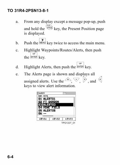
e. The Alerts page is shown and displays all
assigned alerts. Use the , , , andkeys to view alert information.
TPG1227_01
6-4

TO 31R4-2PSN13-8-1
CHAPTER 7OPERATION CHECKS
7.1 OPERATION CHECKS.Refer to TO/TM chapter 18.• INDICATION— High FOM/Position ErrorAction—Check SV Sky View page or SV Status page.Action — Ensure you are tracking at least foursatellites.Action— Ensure the antenna is not masked. Moveto position where antenna has clear view of the sky.If you are stationary and the antenna is masked byfoliage, select the Average mode of operation.Action—Ensure keys are loaded and you have currentkey. Check Crypto Fill page.Reference— SV Sky View page (TO/TM paragraph13.2), SV Status page (TO/TM paragraph 13.4),Crypto Fill page (TO/TM paragraph 7.2)
• INDICATION— Unexpected Power OffAction— Check Power Saver page, Auto-Off Timerfield.Action— Check for dead battery. If DAGR will notpower-on at all, the battery is dead. Replace it.
7-1

TO 31R4-2PSN13-8-1
Reference— Power Saver page (TO/TM paragraph7.5)
• INDICATION — ON display sequence does notcomplete. DAGR shuts off when new batteries areinstalled.Action— Push PWR key repeatedly until DAGR stayson. If DAGR still does not stay on, replace batteries.Reference— Battery page (TO/TM paragraph 7.6)
• INDICATION— Obtaining a position fix takes toolongAction— Initialize position, date, and time. CheckPresent Position page.Action— Ensure you are tracking satellites. CheckSV Sky View page or SV Status page.Action— Ensure the antenna is not masked. Moveto position where antenna has clear view of the sky.If you can not move and the antenna is masked byfoliage, select the Average mode of operation (TO/TMparagraph 6.2.23).Reference—Present Position page (TO/TM paragraph9.5), SV Sky View page (TO/TM paragraph 13.2), SVStatus page (TO/TM paragraph 13.4)
• INDICATION — DAGR not tracking satellites(display fields blinking)
7-2

TO 31R4-2PSN13-8-1
Action—Check SV Sky View page or SV Status page.Action— Ensure DAGR is not in Standby mode orRehearsal modeAction— Ensure the antenna is not masked. Move toposition where antenna has clear view of the sky.Action— If the DAGR has been in Continuous modewhile masked, recycle power or select Standby andthen Fix or Continuous mode.Reference— SV Sky View page (TO/TM paragraph13.2), SV Status page (TO/TM paragraph 13.4)
• INDICATION— Position does not agree with map orother navigation sourcesAction— Check Present Position page.Action — Check for proper datum and spheroid(ellipsoid).Reference — Present Position page (TO/TMparagraph 9.5)
• INDICATION— Navigation information does notagree with map or other navigation sourcesAction— Check NAV Displays pages.Action — Ensure waypoint datum matches setupdatum.Action— Check coordinates system if using MGRSand second letter of 100,000 meter square designationis different.
7-3

TO 31R4-2PSN13-8-1
Action— Check for proper range and ground speedunits (metric, English, or nautical)Reference— NAV Displays page (TO/TM paragraph9.4), Waypoint Editor page (TO/TM paragraph 8.3),Present Position page (TO/TM paragraph 9.5)
• INDICATION— Azimuth does not agree with othernavigation sourcesAction— Check NAV Displays pages.Action— Ensure MAGVAR type, direction, and valuein setup matches your map or other navigation source.Action— Check for proper north reference (magnetic,grid, or true)Reference— NAV Displays page (TO/TM paragraph9.4), Present Position page (TO/TM paragraph 9.5)
• INDICATION— Elevation does not agree with mapor other navigation sourcesAction— Check Present Position page.Action— Check for proper elevation reference. MSLis normally used.Action— Check to see if you are in elevation hold onthe present position display. Ensure you are tracking atleast four satellites so that elevation can be calculatedaccurately. Check SV Sky View or SV Status pages.Select AUTOMATIC elevation hold in setup.
7-4

TO 31R4-2PSN13-8-1
Reference—Present Position page (TO/TM paragraph9.5), SV Sky View page (TO/TM paragraph 13.2), SVStatus page (TO/TM paragraph 13.4)
• INDICATION— DAGR will not compute groundspeed, track, steering, time to go, minimum missdistance, or glide path deviationAction — The DAGR internal compass may bedisabled or need orientation. Check Internal Compasspage.Action— You may not be moving fast enough. Youmust move at least 0.5 m/s (approx 1.8 K/hr or 1 mph).Action — Ensure you are not in Standby mode.In Standby, the DAGR does not track satellites orcompute navigation information.Reference — Internal Compass page (TO/TMparagraph 10.3)
• INDICATION— Averaging operating mode counterwill not incrementAction— Check Present Position page.Action— Ensure the DAGR has a good positionfix. The counter will not begin incrementing until 13seconds after a position fix is obtained.Reference — Present Position page (TO/TMparagraph 9.5)
• INDICATION—Multiple symptoms
7-5

TO 31R4-2PSN13-8-1
Action— Check Test Summary page.Action— Clear temporary receiver information faults(some information may reappear after it is cleared).Reference— Test Summary page (TO/TM paragraph12.2)
7-6

TO 31R4-2PSN13-8-1
CHAPTER 8DATA TRANSFER
8.1 DAGR TO DAGR DATA TRANSFER.Refer to TO/TM paragraphs 11.2 and 11.2.3 (procedure a).
a. Connect both DAGRs together with the DAGRto DAGR data cable using the J2 externalconnector on both units.
b. Power both DAGRs on.
c. On both DAGRs, push the key. TheReceiver Status display is shown.
TPG2965_01
d. Use the or keys to view the functionset status.
8-1
TO 31R4-2PSN13-8-1
e. If in the Advanced function set, proceed with the
next step. If already in Basic, push the key,then proceed to step j.
f. Push the key. Highlight Select Function Set,
then push the key.
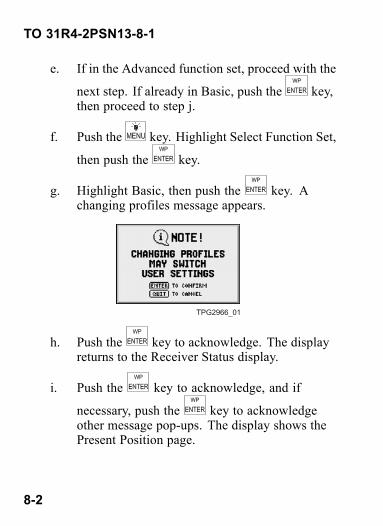
g. Highlight Basic, then push the key. Achanging profiles message appears.
TPG2966_01
h. Push the key to acknowledge. The displayreturns to the Receiver Status display.
i. Push the key to acknowledge, and if
necessary, push the key to acknowledgeother message pop-ups. The display shows thePresent Position page.
8-2

TO 31R4-2PSN13-8-1
TPG0164_05
j. Push the key twice to access the Main menu.
k. Highlight Communications, then push thekey.
l. Highlight Data Transfer, then push the key.The Data Transfer page is displayed.
TPG2967_01
m. On the Data Transfer page of the sending
DAGR, push the key to highlight a field.
8-3
TO 31R4-2PSN13-8-1
n. Use the or keys to highlight the COMPort field.
o. Push the key, then highlight COM Port 1,
then push the key.
p. Use the or keys to highlight the Modefield.
q. Push the key, then highlight DAGR, then
push the key.
r. Use the or keys to highlight the DataTo Transfer field.
s. Push the key, then highlight the type of data
to be sent, then push the key.
NOTEIf transferring waypoint data, set the FromWP and To WP fields to the appropriaterange of waypoints needed, otherwise all999 waypoints will be transferred.
8-4
TO 31R4-2PSN13-8-1
t. On the Data Transfer page of the sending
DAGR, push the key.
u. Highlight Start Data XFR, then push thekey to initiate the data transfer process.
v. Messages show on both DAGR displaysindicating the data transfer is starting, inprogress, complete, aborted, or failed. Followinstructions on display.
w. When data transfer is complete, disconnect thedata cable assembly and perform other DAGRoperations as desired.
NOTEIf an undesired power down message is
displayed, push the key to cancelthe power down. The receiving DAGRswitches to Standby mode.
8.2 CRYPTO KEY ENTRY USING KYK-13.Refer to TO/TM paragraphs 7.2 and 7.2.3 (procedure c).
a. Power the DAGR on.
8-5
TO 31R4-2PSN13-8-1
b. Push the key twice to access the Main menu.
c. Highlight Receiver Setup, then push thekey.
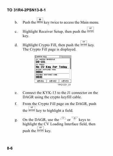
d. Highlight Crypto Fill, then push the key.The Crypto Fill page is displayed.
TPG1231_01
e. Connect the KYK-13 to the J1 connector on theDAGR using the crypto keyfill cable.
f. From the Crypto Fill page on the DAGR, push
the key to highlight a field.
g. On the DAGR, use the or keys tohighlight the CV Loading Interface field, then
push the key.
8-6
TO 31R4-2PSN13-8-1
h. On the DAGR, highlight DS-102, then push the
key.
i. Set the KYK-13 selector switch to the positionthat contains the crypto key.
j. Set the KYK-13 mode switch to ON. The lighton the KYK-13 flashes (for red key only),showing a successful crypto key.
k. Set the KYK-13 mode switch to OFF.
l. Disconnect the KYK-13 and cable from theDAGR.
m. On the DAGR, acknowledge any messages andobserve the CV Status field on the Crypto Fillpage.
8.3 RED CRYPTO KEY ENTRY USING AN/CYZ-10.Refer to TO/TM paragraphs 7.2 and 7.2.3 (procedure e).
a. Power the DAGR on.
b. Push the key twice to access the Main menu.
c. Highlight Receiver Setup, then push thekey.
8-7
TO 31R4-2PSN13-8-1
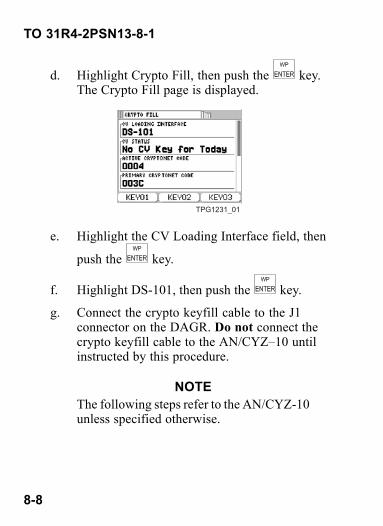
d. Highlight Crypto Fill, then push the key.The Crypto Fill page is displayed.
TPG1231_01
e. Highlight the CV Loading Interface field, then
push the key.
f. Highlight DS-101, then push the key.
g. Connect the crypto keyfill cable to the J1connector on the DAGR. Do not connect thecrypto keyfill cable to the AN/CYZ–10 untilinstructed by this procedure.
NOTEThe following steps refer to the AN/CYZ-10unless specified otherwise.
8-8
TO 31R4-2PSN13-8-1
h. Power the AN/CYZ-10 on (if not alreadypowered on). The display shows SOI RADIOSUPERVISOR.
i. Select RADIO from the display.
j. Display shows SETUP COMSEC TIME. SelectCOMSEC from the display.
k. Display shows VG LD RV AK MK VU. SelectLD from the display.
l. Display shows TEK KEK. Select TEK from thedisplay.
m. Push the PgDN or PgUP keys, as required, toview the desired key, then push the ENTR key.
NOTEWhile performing the following steps, ig-nore all display instructions relating to anRT.
n. Display shows QUIT (Key Name/Number)XMT. Select QUIT from the display.
o. Display shows CONNECT ANCD TO RT(WAIT) (↓). Push the down arrow key (↓).
8-9

TO 31R4-2PSN13-8-1
p. Display shows PRESS (LOAD) ON RT. Connectthe crypto keyfill cable to the AN/CYZ-10.The crypto key is automatically loaded into theDAGR.
q. Acknowledge any DAGR messages and observethe CV Status field on the Crypto Fill page.
r. After the key is loaded, disconnect the cryptokeyfill cable from the AN/CYZ-10 and theDAGR.
8.4 BLACK CRYPTO KEY ENTRY USINGAN/CYZ-10.Refer to TO/TM paragraphs 7.2 and 7.2.3 (proceduref). Procedures are written for AN/CYZ-10 softwareapplication F4.09. When in doubt about the applicationversion or operation, contact the COMSEC custodian.
8.4.1 Set Parameters on AN/CYZ-10.
a. Connect the AN/CYZ-10 fill cable to theAN/CYZ-10.
b. Power the AN/CYZ-10 on.
c. From the main menu, select APPL, then pushthe ENTR key.
8-10

TO 31R4-2PSN13-8-1
d. Select software version, then push the ENTRkey.
e. Display shows LOADING APPLICATION.
NOTEIf display shows AUDIT TRAIL IS FULL,push the CLR key, then notify supervisor.
f. Select UTILITY, then push the ENTR key.
g. Select SETUP, then push the ENTR key.
h. Select PROTOCOL, then push the ENTR key.
i. Select CFD, then push the ENTR key.
j. The fill devices menu is displayed.
k. Select the fill device, then push the ENTR key.
l. The setup menu is displayed.
m. Push the ABORT key.
n. The main menu is displayed.
o. Select RECV, then push the ENTR key.
p. The connect to station message is displayed.
8-11

TO 31R4-2PSN13-8-1
8.4.2 Load BKAUPD Tape into KOI-18. These stepsrefer to the AN/CYZ-10.
a. Connect the AN/CYZ-10 cable to the KOI-18.
b. Put the BKAUPD tape into the KOI-18.
c. Push the RECV key.
d. LOAD IN PROCESS is displayed.
e. Pull the tape through the KOI-18.
f. DATA RECEIVED is displayed.
g. Push the RECV key.
h. LOAD IN PROCESS is displayed.
i. Pull the tape through the KOI-18 again.
j. ENTER TEXT ID is displayed.
k. Enter the text ID for the key, then push theENTR key.
l. ENTER SHORT TITLE is displayed.
m. Enter the short title for the key.
n. ENTER SEGMENT NUMBER is displayed.
o. Enter the segment number from 1 to 15.
p. ENTER REG NUMBER is displayed.
8-12

TO 31R4-2PSN13-8-1
q. Enter the reg number.
r. SELECT CLASSIFICATION is displayed.
s. From the menu, select the classification.
8.4.3 Load Crypto Key Tape into KOI-18. These stepsrefer to the AN/CYZ-10.
a. Put the crypto key variables tape into theKOI-18.
b. Push the RECV key.
c. LOAD IN PROCESS is displayed.
d. Pull the tape through the KOI-18.
e. DATA RECEIVED is displayed.
f. Push the RECV key.
g. LOAD IN PROCESS is displayed.
h. Pull the tape through the KOI-18 again.
i. ENTER TEXT ID is displayed.
j. Enter the text ID for the key, then push theENTR key.
k. ENTER SHORT TITLE is displayed.
l. Enter the short title for the key.
8-13

TO 31R4-2PSN13-8-1
m. ENTER SEGMENT NUMBER is displayed.
n. Enter the segment number from 1 to 3.
o. ENTER REG NUMBER is displayed.
p. Enter the reg number.
q. SELECT CLASSIFICATION is displayed.
r. From the menu, select the classification.
8.4.4 Set Up DAGR.
a. Power the DAGR on.
b. Push the key twice to access the Main menu.
c. Highlight Receiver Setup, then push thekey.
d. Highlight Crypto Fill, then push the key.The Crypto Fill page is displayed.
8-14
TO 31R4-2PSN13-8-1
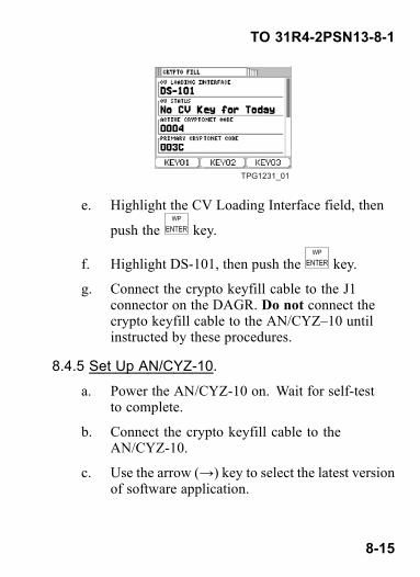
TPG1231_01
e. Highlight the CV Loading Interface field, then
push the key.
f. Highlight DS-101, then push the key.
g. Connect the crypto keyfill cable to the J1connector on the DAGR. Do not connect thecrypto keyfill cable to the AN/CYZ–10 untilinstructed by these procedures.
8.4.5 Set Up AN/CYZ-10.
a. Power the AN/CYZ-10 on. Wait for self-testto complete.
b. Connect the crypto keyfill cable to theAN/CYZ-10.
c. Use the arrow (→) key to select the latest versionof software application.
8-15

TO 31R4-2PSN13-8-1
NOTEConfiguration of the AN/CYZ-10 can vary.The application may automatically load.When in doubt about the AN/CYZ-10 oper-ation, contact the COMSEC custodian.
d. Select APPL, then push the ENTR key. Wait forthe software application to load.
e. Select the appropriate software version, thenpush the ENTR key.
f. LOADING APPLICATION is displayed.
NOTEIf display shows AUDIT TRAIL IS FULL,push the CLR key, then notify supervisor.
g. If LMD shows in the upper right corner ofdisplay, proceed to step o. If LMD is notdisplayed, continue with the next step.
h. Use the arrow (→) key to select UTILITY.
i. Push the ENTR key.
j. Push the ENTR key again to display SETUP.
k. Push the ENTR key again to displayPROTOCOL.
8-16
TO 31R4-2PSN13-8-1
l. Use the arrow (→) key to highlight LMD, thenpush the ENTR key.
m. Push the ABORT key. The display has LMD inthe upper right corner.
n. Push the ENTR key for XMIT.
o. Push the ENTR key again to select FILL.
8.4.6 Load BKAUPD Key into DAGR. These steps referto the AN/CYZ-10.
a. Push the PgUP or PgDN key to select theBKAUPD parameters key name.
NOTEKey name may vary depending on the as-signed name. When in doubt of which keyto use, contact the COMSEC custodian.
b. Push the ENTR key. XMT is shown in the lowerright corner of the display.
c. Use the arrow (→) key to highlight sEnd.
d. Push the ENTR key, or push the SEND key.
e. Push the ENTR key for DIRECT.
f. Push the SEND key, or push the ENTR key.
8-17

TO 31R4-2PSN13-8-1
g. The keys being transferred and the message 1MSGS TRANSMITTED are displayed.
h. After the BKAUPD parameters key is loaded,use the arrow (→) key to select NEW.
i. Push the ENTR key.
8.4.7 Load Crypto Key into DAGR. These steps refer tothe AN/CYZ-10.
a. Push the PgUP or PgDN keys to select the cryptovariables key.
b. Push the ENTR key. XMT is shown in the lowerright corner of the display.
c. Use the arrow (→) key to highlight sEnd.
d. Push the ENTR key, or push the SEND key.
e. Push the ENTR key for DIRECT.
f. Push the SEND key, or push the ENTR key.
g. The keys being transferred and the message 1MSGS TRANSMITTED are displayed.
8-18
TO 31R4-2PSN13-8-1
NOTE• The DAGR generates a successful keyload message for each valid and completedblack key received. If the DAGR displaysthe warning INVALID CV LOADED, pushthe ENTER key on the DAGR. The DAGRshould then display VALID CV LOADED.• The BKAUPD parameters and crypto vari-ables are now loaded into the DAGR, andprovide mission coverage for less than 28days.
h. When loading is complete, disconnect the cryptokeyfill cable from the AN/CYZ-10 and theDAGR.
i. Power off the AN/CYZ-10.
j. Power off the DAGR.
8.5 DATA CLEAR.
Data Clear can destroy mission critical data.
Refer to TO/TM paragraphs 12.5 and 12.5.2.
8-19
TO 31R4-2PSN13-8-1
a. From any display except a message pop-up,
push the key, the Present Position page isdisplayed.
b. Push the key twice to access the main menu.
c. Highlight System, then push the key.
d. Highlight Data Clear Options, then push the
key.
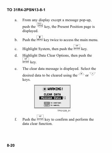
e. The clear data message is displayed. Select the
desired data to be cleared using the orkeys.
TPG1228_01
f. Push the key to confirm and perform thedata clear function.
8-20
TO 31R4-2PSN13-8-1
g. Push the key to acknowledge the clear datapassed message.
8.6 EMERGENCY ZEROIZE.
Emergency zeroize clears ALL mission criticaldata.
Refer to TO/TM paragraphs 7.3.1 and 7.3.3 (procedure a).
a. From any display except a message pop-up, push
the and keys simultaneously.
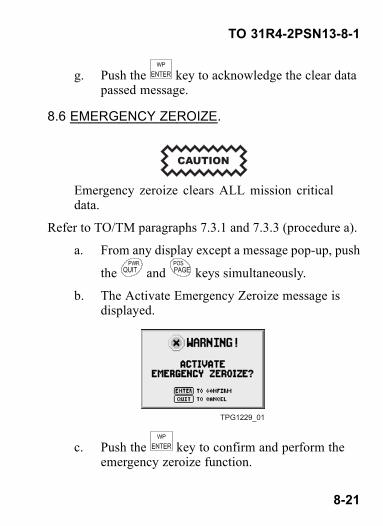
b. The Activate Emergency Zeroize message isdisplayed.
TPG1229_01
c. Push the key to confirm and perform theemergency zeroize function.
8-21
TO 31R4-2PSN13-8-1
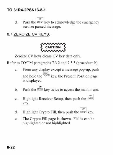
d. Push the key to acknowledge the emergencyzeroize passed message.
8.7 ZEROIZE CV KEYS.
Zeroize CV keys clears CV key data only.
Refer to TO/TM paragraphs 7.3.2 and 7.3.3 (procedure b).
a. From any display except a message pop-up, push
and hold the key, the Present Position pageis displayed.
b. Push the key twice to access the main menu.
c. Highlight Receiver Setup, then push thekey.
d. Highlight Crypto Fill, then push the key.
e. The Crypto Fill page is shown. Fields can behighlighted or not highlighted.
8-22

TO 31R4-2PSN13-8-1
TPG1231_01
f. Push the key.
g. Highlight Zeroize CV Keys, then push thekey.
h. The Activate CV Zeroize message is displayed.
TPG1230_01
i. Push the key to confirm and perform theCV zeroize function.
j. Push the key to acknowledge the CVzeroize passed message.
8-23/(8-24 blank)


TO 31R4-2PSN13-8-1
CHAPTER 9OPERATION UNDER UNUSUAL
CONDITIONS
9.1 AREAS BLOCKING SIGNALS.Refer to TO/TM paragraph 15.2.1.• If operating in a cave environment, place DAGR inStandby mode prior to entering these conditions.
• When back in unobscured conditions from a caveenvironment, set the DAGR to a tracking mode. TheDAGR performs a direct Y-code acquisition (if CVkeys are loaded).
• If operating in a dense foliage environment, placeDAGR in Average mode and keep stationary to acquirecurrent position. Do not move DAGR in Averagemode.
• If DAGR is left in a tracking mode for one hour ormore while obscured, ability to perform direct Y-codeacquisition may be lost.
• When back in unobscured conditions, cycle the DAGRto Standby mode then to a tracking mode. The DAGRperforms a direct Y-code acquisition (if CV keys areloaded).
9-1
TO 31R4-2PSN13-8-1
9.2 ELECTRONIC WARFARE.
To prevent injury or death during spoofing orjamming, the DAGR must be loaded with cur-rent CV keys to operate correctly and improveaccuracy.
9.2.1 Spoofing and Anti-Spoofing. Refer to TO/TMparagraph 15.3.1. Hostile parties may imitate (spoof) GPSsignals causing errors in navigation information. Improveoperation by the following.• Ensure current crypto keys are loaded (Refer to TO/TM
paragraph 7.2).• Command the DAGR to use only satellites transmitting
Y-code signals (Refer to TO/TM paragraph 7.4.2.4).
9.2.2 Jamming and Anti-Jamming. Refer to TO/TMparagraph 15.3.2. Signal interference (jamming) mayoccur due to hostile parties or when operating near largemetal objects, dense foliage, or high power electronicemissions, etc. Improve operation by the following.• Operate the DAGR close to the ground to minimize
reception of ground based signals.
9-2 Change 2

TO 31R4-2PSN13-8-1
• Avoid operating the DAGR near a tank, dense foliage,or a source of high power electronic emissions.
• Block the jamming signal by placing your bodybetween the DAGR and the jamming source.
• Use average mode of operation to acquire presentposition data.
• Use jammer finder procedures to aid in finding sourceof jamming (Refer to TO/TM paragraph 14.5).
• Use the anti-jam accessory when in a host platform.
9-3/(9-4 blank)Change 2


TO 31R4-2PSN13-8-1
CHAPTER 10TROUBLESHOOTING
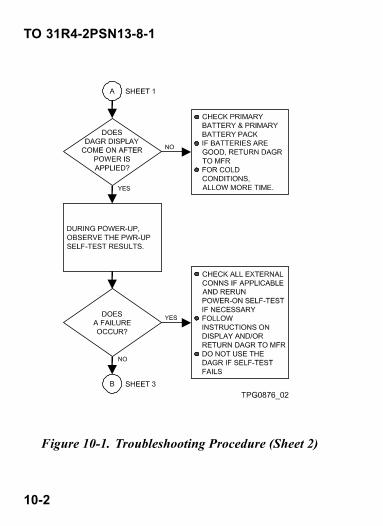
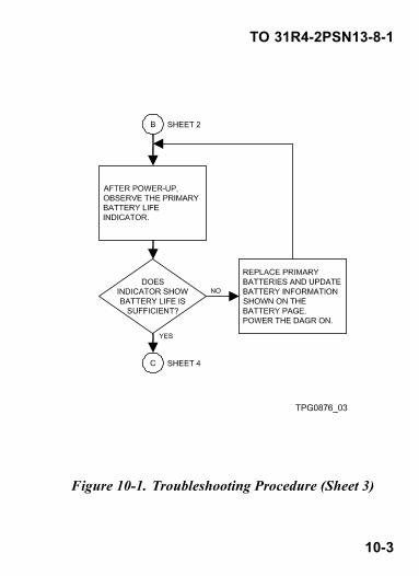
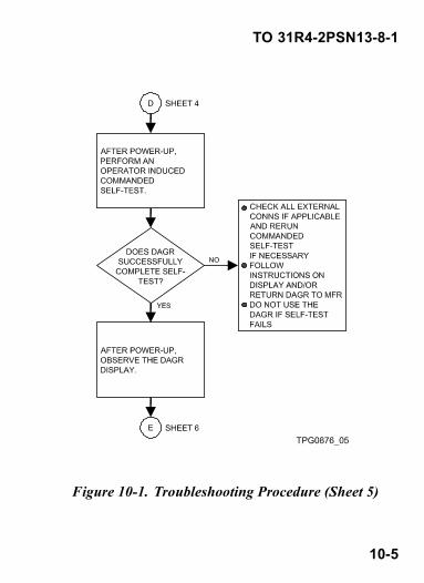
10.1 TROUBLESHOOTING PROCEDURE.Refer to TO/TM chapter 19. Refer to chapter 11 in thismanual for specific information on messages displayed.
Figure 10-1. Troubleshooting Procedure (Sheet 1 of 6)
10-1
TO 31R4-2PSN13-8-1
Figure 10-1. Troubleshooting Procedure (Sheet 2)
10-2
TO 31R4-2PSN13-8-1
Figure 10-1. Troubleshooting Procedure (Sheet 3)
10-3

TO 31R4-2PSN13-8-1
Figure 10-1. Troubleshooting Procedure (Sheet 4)
10-4
TO 31R4-2PSN13-8-1
Figure 10-1. Troubleshooting Procedure (Sheet 5)
10-5

TO 31R4-2PSN13-8-1
Figure 10-1. Troubleshooting Procedure (Sheet 6)
10-6 Change 2

TO 31R4-2PSN13-8-1
CHAPTER 11MESSAGES
11.1 DISPLAYED MESSAGES.Refer to TO/TM chapter 16.
Figure 11-1. Messages (Sheet 1 of 19)
11-1Change 2

TO 31R4-2PSN13-8-1
Figure 11-1. Messages (Sheet 2)
11-2 Change 2
TO 31R4-2PSN13-8-1
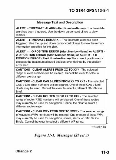
Figure 11-1. Messages (Sheet 3)
11-3Change 2

TO 31R4-2PSN13-8-1
Figure 11-1. Messages (Sheet 4)
11-4 Change 2

TO 31R4-2PSN13-8-1
Figure 11-1. Messages (Sheet 5)
11-5Change 2

TO 31R4-2PSN13-8-1
Figure 11-1. Messages (Sheet 6)
11-6 Change 2

TO 31R4-2PSN13-8-1
Figure 11-1. Messages (Sheet 7)
11-7Change 2

TO 31R4-2PSN13-8-1
Figure 11-1. Messages (Sheet 8)
11-8 Change 2

TO 31R4-2PSN13-8-1
Figure 11-1. Messages (Sheet 9)
11-9Change 2

TO 31R4-2PSN13-8-1
Figure 11-1. Messages (Sheet 10)
11-10 Change 2

TO 31R4-2PSN13-8-1
Figure 11-1. Messages (Sheet 11)
11-11Change 2

TO 31R4-2PSN13-8-1
Figure 11-1. Messages (Sheet 12)
11-12 Change 2
TO 31R4-2PSN13-8-1
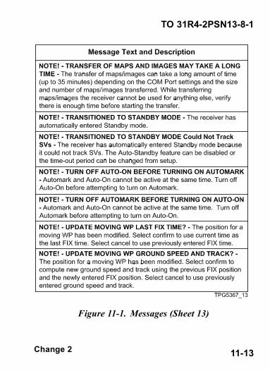
Figure 11-1. Messages (Sheet 13)
11-13Change 2

TO 31R4-2PSN13-8-1
Figure 11-1. Messages (Sheet 14)
11-14 Change 2

TO 31R4-2PSN13-8-1
Figure 11-1. Messages (Sheet 15)
11-15Change 2

TO 31R4-2PSN13-8-1
Figure 11-1. Messages (Sheet 16)
11-16 Change 2

TO 31R4-2PSN13-8-1
Figure 11-1. Messages (Sheet 17)
11-17Change 2

TO 31R4-2PSN13-8-1
Figure 11-1. Messages (Sheet 18)
11-18 Change 2
TO 31R4-2PSN13-8-1
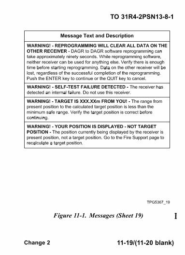
Figure 11-1. Messages (Sheet 19)
11-19/(11-20 blank)Change 2


TO 31R4-2PSN13-8-1
CHAPTER 12BATTERY REPLACEMENT
12.1 PRIMARY BATTERY REPLACEMENT.
Do not mix new with old batteries, mix batterytypes, or reverse battery polarity. Use only fresh/new batteries. Ensure a good memory battery isinstalled. This ensures proper battery life and unitoperation.Refer to TO/TM paragraph 22.6.2. Refer to Fig-ure 12-1.
a. Pull latch on battery pack to release, then removebattery pack.
b. Remove batteries and dispose according to localregulations.
c. Position battery removal strap into batterypack and install new batteries (ensure correctpolarity).
12-1

TO 31R4-2PSN13-8-1
d. To reinstall battery pack, check gasket, positiontab on battery pack in slot on the DAGR, thenpress until battery pack in engaged.
e. Power the DAGR on. Push the key twice toaccess the main menu.
f. Highlight Receiver Setup, then push thekey.
g. Highlight Battery, then push the key. The
Battery page is shown. Use the or keysto access page views.
TPG1232_02
h. Update the Power Batteries Installed field,Battery Type field, and Rechargeable field with
current information. Push the key, thenselect Reset Battery Used.
12-2

TO 31R4-2PSN13-8-1
Figure 12-1. Primary Battery Replacement
12.2 MEMORY BATTERY CHECK.Refer to TO/TM paragraphs 7.6, 7.6.3 (procedure b), and22.6.3.
a. From any display except a message pop-up, push
and hold the key, the Present Position pageis displayed.
12-3

TO 31R4-2PSN13-8-1
b. Push the key twice to access the main menu.
c. Highlight Receiver Setup, then push thekey.
d. Highlight Battery, then push the key.
e. The Battery page is shown. Use the orkeys to access page view.
TPG1232_01
f. Check date in the Memory Battery Installedfield. Memory battery life is approximately eightmonths.
12-4 Change 2

TO 31R4-2PSN13-8-1
CHAPTER 13EXTERNAL INTERFACE
13.1 INSTALLATION TO HOST PLATFORM.
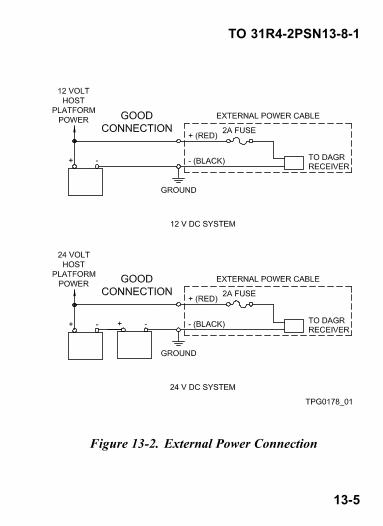
Failure to observe correct polarity when installingthe external DC power cable may result in dam-age to the DAGR. Fuse is located in the positive(red) lead of the external power cable.
NOTEInternal primary power batteries are not requiredwhile using external power, but may remain in-stalled. The memory battery should always re-main installed.
Refer to Figure 13-1 for a diagram of the host platforminterconnection, and to Figure 13-2 for external powerconnection. Refer to TO/TM paragraph 20.3.3.
a. Pull outward on two slide pins located on mount.Install DAGR into host platform mount.
13-1Change 2
TO 31R4-2PSN13-8-1
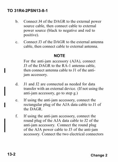
b. Connect J4 of the DAGR to the external powersource cable, then connect cable to externalpower source (black to negative and red topositive).
c. Connect J3 of the DAGR to the external antennacable, then connect cable to external antenna.
NOTEFor the anti-jam accessory (AJA), connectJ3 of the DAGR to the RA-1 antenna cable,then connect antenna cable to J1 of the anti-jam accessory.
d. J1 and J2 are connected as needed for datatransfer with an external device. (If not using theanti-jam accessory, go to step g.)
e. If using the anti-jam accessory, connect therectangular plug of the AJA data cable to J1 ofthe DAGR.
f. If using the anti-jam accessory, connect theround plug of the AJA data cable to J2 of theanti-jam accessory. Connect the round plugof the AJA power cable to J3 of the anti-jamaccessory. Connect the two electrical connectors
13-2 Change 2

TO 31R4-2PSN13-8-1
of the AJA power cable (black to negative andred to positive) to the host platform DC powersource (switched).
NOTEConnect the anti-jam accessory to a DCpower source that can be switched off. Ifthe DC power source is not switched offwhen the anti-jam accessory is not in use,an unnecessary power drain will result inthe host platform.
g. The DAGR automatically updates itself to usingexternal power. No reconfiguration is necessarywhen using external antenna.
13-3Change 2

TO 31R4-2PSN13-8-1
Figure 13-1. Host Platform Interconnection
13-4 Change 2
TO 31R4-2PSN13-8-1
Figure 13-2. External Power Connection
13-5
TO 31R4-2PSN13-8-1
13.2 REMOVAL FROM HOST PLATFORM.Refer to TO/TM paragraph 22.2.
a. Power DAGR off.
b. Remove any cables from connectors J1, J2, J3,and J4.
c. Pull outward on two slide pins located on mountand twist to lock into open position.
d. Remove DAGR from host platform mount andrelease slide pins.
13-6
TO 31R4-2PSN13-8-1
CHAPTER 14MENU TREE
14.1 MAIN MENU AND SUBMENUS.Refer to TO/TM paragraphs 6.2.1 through 6.2.8. Onlymain menu and submenu listings are shown. Page andfield menus are not shown, but have accessible relatedmenus and/or editors. Menu structure is as follows:• Main Menu — Provides submenu choices.• Submenu — Provides page or function choices.• Page Menu — Provides specific functions or editorsassociated with the page.
• Field Menu — Provides specific functions or editorsassociated with the field.
With a page displayed or a field selected, the correspondingmenu may be viewed by pushing the MENU key. Pushingthe QUIT key backs out of the menu and return to theprevious display. When the menu selection has an arrowsymbol to its right, push the ENTER key to view thesubmenu. Items that are not currently available aredisabled and appear as light gray text.
Advanced menu items are only available when theadvanced function set is selected.
14-1

TO 31R4-2PSN13-8-1
Figure 14-1. Menu Tree (Sheet 1 of 3)
14-2

TO 31R4-2PSN13-8-1
Figure 14-1. Menu Tree (Sheet 2)
14-3

TO 31R4-2PSN13-8-1
Figure 14-1. Menu Tree (Sheet 3)
14-4 Change 2

By Order of the Secretaries of the Air Force, Army, and Navy (Including the Marine Corps): Official: BRUCE CARLSON General, USAF Commander, Air Force Materiel Command T. MICHAEL MOSLEY General, USAF Chief of Staff Official: JOYCE E. MORROW Administrative Assistant to the Secretary of the Army 0630301 PETER J. SCHOOMAKER General, USA Chief of Staff Official: J. D. WILSON Program Manager Communications Systems Marine Corps Systems Command MICHAEL W. HAGEE General, USMC Commandant of the Marine Corps Official: DENNIS M. BAUMAN Program Executive Officer Command, Control, Communications, Computers Intelligence and Space Official: VERN CLARK Admiral, USN Chief of Naval Operations PIN: 081443-000