DADF R1
166
Feb 21 2008 Service Manual Feeder DADF-R1
description
Service manual for dadf-R1
Transcript of DADF R1

Feb 21 2008
Service Manual
FeederDADF-R1

ApplicationThis manual has been issued by Canon Inc. for qualified persons to learn technical theory, installation, maintenance, and repair
of products. This manual covers all localities where the products are sold. For this reason, there may be information in this
manual that does not apply to your locality.
CorrectionsThis manual may contain technical inaccuracies or typographical errors due to improvements or changes in products. When
changes occur in applicable products or in the contents of this manual, Canon will release technical information as the need
arises. In the event of major changes in the contents of this manual over a long or short period, Canon will issue a new edition
of this manual.
The following paragraph does not apply to any countries where such provisions are inconsistent with local law.
TrademarksThe product names and company names used in this manual are the registered trademarks of the individual companies.
CopyrightThis manual is copyrighted with all rights reserved. Under the copyright laws, this manual may not be copied, reproduced or
translated into another language, in whole or in part, without the written consent of Canon Inc.
COPYRIGHT © 2001 CANON INC.Printed in Japan
CautionUse of this manual should be strictly supervised to avoid disclosure of confidential information.

Introduction
Symbols UsedThis documentation uses the following symbols to indicate special information:
Symbol Description
Indicates an item of a non-specific nature, possibly classified as Note, Caution, or Warning.
Indicates an item requiring care to avoid electric shocks.
Indicates an item requiring care to avoid combustion (fire).
Indicates an item prohibiting disassembly to avoid electric shocks or problems.
Indicates an item requiring disconnection of the power plug from the electric outlet.
Indicates an item intended to provide notes assisting the understanding of the topic in question.
Indicates an item of reference assisting the understanding of the topic in question.
Provides a description of a service mode.
Provides a description of the nature of an error indication.
Memo
REF.

Introduction
The following rules apply throughout this Service Manual:1. Each chapter contains sections explaining the purpose of specific functions and the relationship between electrical and mechanical systems with refer-
ence to the timing of operation.In the diagrams, represents the path of mechanical drive; where a signal name accompanies the symbol , the arrow indicates thedirection of the electric signal.The expression "turn on the power" means flipping on the power switch, closing the front door, and closing the delivery unit door, which results insupplying the machine with power.
2. In the digital circuits, '1'is used to indicate that the voltage level of a given signal is "High", while '0' is used to indicate "Low".(The voltage value, how-ever, differs from circuit to circuit.) In addition, the asterisk (*) as in "DRMD*" indicates that the DRMD signal goes on when '0'.In practically all cases, the internal mechanisms of a microprocessor cannot be checked in the field. Therefore, the operations of the microprocessorsused in the machines are not discussed: they are explained in terms of from sensors to the input of the DC controller PCB and from the output of theDC controller PCB to the loads.
The descriptions in this Service Manual are subject to change without notice for product improvement or other purposes, and major changes will be com-municated in the form of Service Information bulletins.All service persons are expected to have a good understanding of the contents of this Service Manual and all relevant Service Information bulletins and beable to identify and isolate faults in the machine."

Contents
Contents
Chapter 1 Specifications
1.1 Product Specifications ................................................................................................................................1- 11.1.1 ADF Specifications ..................................................................................................................................................1- 1
1.2 Names of Parts ...........................................................................................................................................1- 21.2.1 External View...........................................................................................................................................................1- 21.2.2 Cross Section ..........................................................................................................................................................1- 3
1.3 Using the Machine......................................................................................................................................1- 31.3.1 Original Set Indicator ...............................................................................................................................................1- 3
Chapter 2 Installation
2.1 Unpacking and Checking the Components ................................................................................................2- 12.1.1 Points to Note About Installation .............................................................................................................................2- 12.1.2 Checking the Contents (DADF-R1) .........................................................................................................................2- 12.1.3 Checking the Contents (Power Supply Unit-S1)......................................................................................................2- 1
2.2 Installation Procedure.................................................................................................................................2- 22.2.1 Turning Off the Host Machine (imagePRESS C1 Series) .......................................................................................2- 22.2.2 Points to Note When Turning ON/OFF the power of Host Machine (imagePRESS C7000Series) .........................2- 22.2.3 Installing the DADF-R1 (imagePRESS C1 Series)..................................................................................................2- 32.2.4 Installing the DADF-R1 (imagePRESS C7000Series).............................................................................................2- 62.2.5 Installing the Option Power Supply Unit-S1 (imagePRESS C1 Series) ................................................................2- 10
2.3 Making Adjustments .................................................................................................................................2- 122.3.1 Adjustment (imagePRESS C1Series, imagePRESS C7000Series)......................................................................2- 122.3.2 Adjusting the Right Angle (imagePRESS C1Series, imagePRESS C7000Series) ..............................................2- 122.3.3 Horizontal Registration Adjustment (imagePRESS C1Series, imagePRESS C7000Series) ............................... 2- 132.3.4 Leading Edge Registration Adjustment (imagePRESS C1Series, imagePRESS C7000Series) .........................2- 142.3.5 Horizontal Registration Adjustment (Fine Adjustment) (imagePRESS C1Series, imagePRESS C7000Series) ...2- 172.3.6 Leading Edge Registration Adjustment (Fine Adjustment for Both Sides) (imagePRESS C1Series, imagePRESS
C7000Series).............................................................................................................................................................2- 182.4 Attaching the Labels etc. ..........................................................................................................................2- 18
2.4.1 Attaching the Cleaning Instructions Label (imagePRESS C1Series, imagePRESS C7000Series) .....................2- 182.4.2 Attaching the Manual Feeder Placement Label (imagePRESS C1Series, imagePRESS C7000Series).............2- 18
Chapter 3 Functions
3.1 Basic Construction......................................................................................................................................3- 13.1.1 Overview of Electrical Circuit...................................................................................................................................3- 13.1.2 Inputs to ADF Controller PCB.................................................................................................................................. 3- 23.1.3 Outputs from ADF Controller PCB...........................................................................................................................3- 4
3.2 Basic Operation ..........................................................................................................................................3- 43.2.1 Outline .....................................................................................................................................................................3- 43.2.2 Outline .....................................................................................................................................................................3- 63.2.3 CW Pickup/Delivery.................................................................................................................................................3- 63.2.4 Pre-Reversal/Reversal/Delivery ..............................................................................................................................3- 73.2.5 Manual Feeder Pickup/Delivery...............................................................................................................................3- 8
3.3 Document Detection ...................................................................................................................................3- 93.3.1 Outline .....................................................................................................................................................................3- 93.3.2 Detecting the Presence/Absence of an Original......................................................................................................3- 93.3.3 Original Size Detection 1 .......................................................................................................................................3- 103.3.4 Original Size Detection 2 .......................................................................................................................................3- 11
Contents
3.3.5 Detecting the Presence/Absence of an Original in the Manual Feeder .................................................................3- 143.4 Document Pickup/Separation................................................................................................................... 3- 15
3.4.1 Outline....................................................................................................................................................................3- 153.4.2 Moving Up/Down the Pickup Roller Unit ................................................................................................................3- 153.4.3 Switching the Separation Pressure........................................................................................................................3- 173.4.4 Separation Sensor (S4) and Skew Sensor (S5) ....................................................................................................3- 183.4.5 Controlling the Pickup Motor (M3) .........................................................................................................................3- 193.4.6 Controlling the Separation Motor (M4)...................................................................................................................3- 193.4.7 Sequence of Operations ........................................................................................................................................3- 20
3.5 Document Feeding/Delivery ..................................................................................................................... 3- 203.5.1 Outline....................................................................................................................................................................3- 203.5.2 Controlling the Belt Motor (M2) ..............................................................................................................................3- 213.5.3 Controlling the Delivery Motor (M5) .......................................................................................................................3- 22
3.6 Feeding Unit ............................................................................................................................................. 3- 223.6.1 Outline of CW Pickup/Delivery...............................................................................................................................3- 223.6.2 CW Pickup/Delivery Fixed Reading .......................................................................................................................3- 233.6.3 CW Pickup/Delivery (stream reading) ...................................................................................................................3- 263.6.4 Double-Sided Originals (fixed reading) .................................................................................................................3- 303.6.5 Fixed Reading (continuous; double-sided original)................................................................................................3- 343.6.6 Controlling the Reversal Motor (M1) ......................................................................................................................3- 383.6.7 Manual Feeder Pickup/Delivery Operation ............................................................................................................3- 39
3.7 Detecting Jams......................................................................................................................................... 3- 403.7.1 Overview ...............................................................................................................................................................3- 403.7.2 List of Jam Code....................................................................................................................................................3- 413.7.3 Alarm Code............................................................................................................................................................3- 44
3.8 Power Supply ........................................................................................................................................... 3- 443.8.1 Overview................................................................................................................................................................3- 44
Chapter 4 Parts Replacement Procedure
4.1 Removing from the Host Machine .............................................................................................................. 4- 14.1.1 Feeder......................................................................................................................................................................4- 1
4.1.1.1 Disconnecting the DADF.......................................................................................................................................................... 4- 14.2 External Covers .......................................................................................................................................... 4- 1
4.2.1 External Covers .......................................................................................................................................................4- 14.2.1.1 External Covers ....................................................................................................................................................................... 4- 1
4.2.2 Front Cover ..............................................................................................................................................................4- 14.2.2.1 Removing the Front Cover....................................................................................................................................................... 4- 1
4.2.3 Main Cover...............................................................................................................................................................4- 14.2.3.1 Removing the Main Cover ....................................................................................................................................................... 4- 1
4.2.4 ADF Controller Cover...............................................................................................................................................4- 24.2.4.1 Removing the ADF Controller Cover ....................................................................................................................................... 4- 2
4.2.5 Side Guide Lock.......................................................................................................................................................4- 24.2.5.1 Side Guide Lock....................................................................................................................................................................... 4- 2
4.3 Drive System .............................................................................................................................................. 4- 24.3.1 Reversal Motor.........................................................................................................................................................4- 2
4.3.1.1 Preparation for Removing the Reversal Motor Unit ................................................................................................................. 4- 24.3.1.2 Removing the Reversal Motor Unit ......................................................................................................................................... 4- 2
4.3.2 Pickup Motor ............................................................................................................................................................4- 34.3.2.1 Preparation for Removing the Pickup Motor Unit..................................................................................................................... 4- 34.3.2.2 Removing the Pickup Motor Unit ............................................................................................................................................ 4- 3
4.3.3 Delivery Motor..........................................................................................................................................................4- 34.3.3.1 Preparation for Removing the Delivery Motor.......................................................................................................................... 4- 34.3.3.2 Removing the Delivery Motor................................................................................................................................................... 4- 4
4.3.4 Belt Motor Unit .........................................................................................................................................................4- 44.3.4.1 Preparation for Removing the Belt Motor Unit ......................................................................................................................... 4- 44.3.4.2 Removing the Belt Motor Unit .................................................................................................................................................. 4- 4
Contents
4.4 Document Feeding System ........................................................................................................................4- 44.4.1 Registration Roller ................................................................................................................................................... 4- 4
4.4.1.1 Preparation for Removing the Registration Roller ................................................................................................................... 4- 44.4.1.2 Removing the Registration Roller ............................................................................................................................................ 4- 4
4.4.2 Reversing Roller ......................................................................................................................................................4- 54.4.2.1 Preparation for Removing the Reversing Roller ...................................................................................................................... 4- 54.4.2.2 Removing the Reversing Roller ............................................................................................................................................... 4- 5
4.4.3 Feed Belt ................................................................................................................................................................. 4- 64.4.3.1 Preparation for Removing the Feeding Belt............................................................................................................................. 4- 64.4.3.2 Removing the Feeding Belt...................................................................................................................................................... 4- 64.4.3.3 Attaching the Feeding Belt....................................................................................................................................................... 4- 6
4.4.4 Separation Belt ........................................................................................................................................................4- 74.4.4.1 Preparation for Removing the Separation Belt ........................................................................................................................ 4- 74.4.4.2 Removing the Separation Belt ................................................................................................................................................. 4- 7
4.4.5 Delivery Roller .........................................................................................................................................................4- 84.4.5.1 Preparation for Removing the Delivery Roller.......................................................................................................................... 4- 84.4.5.2 Removing the Delivery Roller .................................................................................................................................................. 4- 8
4.4.6 Pickup Rollor ...........................................................................................................................................................4- 94.4.6.1 Removing the Pickup Roller..................................................................................................................................................... 4- 9
4.4.7 Separation Rollor...................................................................................................................................................4- 104.4.7.1 Preparation for Removing the Separation Roller ................................................................................................................... 4- 104.4.7.2 Removing the Separation Roller ............................................................................................................................................ 4- 10
4.4.8 Feeding (pull-off) Roller .........................................................................................................................................4- 114.4.8.1 Preparation for Removing the Feeding (pull-off) Roller ......................................................................................................... 4- 114.4.8.2 Removing the Feeding (pull-off) Roller .................................................................................................................................. 4- 11
4.4.9 Document Tray ......................................................................................................................................................4- 124.4.9.1 Removing the Original Tray ................................................................................................................................................... 4- 12
4.4.10 Manual Feed Registration Roller .........................................................................................................................4- 124.4.10.1 Preparation for Removing the Manual Feed Registration ................................................................................................... 4- 124.4.10.2 Removing the Manual Feed Registration Roller ................................................................................................................. 4- 13
Chapter 5 Maintenance
5.1 User Maintenance ......................................................................................................................................5- 15.1.1 User maintenance item............................................................................................................................................5- 1
5.2 Maintenance and Inspection.......................................................................................................................5- 15.2.1 Periodically Replaced Parts.....................................................................................................................................5- 1
5.2.1.1 Periodiccally Replaced Parts ................................................................................................................................................... 5- 15.2.2 Durables ..................................................................................................................................................................5- 1
5.2.2.1 Durables................................................................................................................................................................................... 5- 15.2.3 Periodical Servicing .................................................................................................................................................5- 1
5.2.3.1 Scheduled Servicing Chart ...................................................................................................................................................... 5- 15.2.4 Cleaning ..................................................................................................................................................................5- 3
5.2.4.1 Outline...................................................................................................................................................................................... 5- 35.2.4.2 Separation Assembly ............................................................................................................................................................... 5- 35.2.4.3 Registration Roller ................................................................................................................................................................... 5- 45.2.4.4 Copyboard Glass ..................................................................................................................................................................... 5- 55.2.4.5 Belt Assembly .......................................................................................................................................................................... 5- 65.2.4.6 Original Trailing Edge Sensor .................................................................................................................................................. 5- 65.2.4.7 Original Sensor ........................................................................................................................................................................ 5- 65.2.4.8 Separation Paper/Skew Paper Sensor .................................................................................................................................... 5- 65.2.4.9 Pre-Registration Roller Paper Sensor...................................................................................................................................... 5- 75.2.4.10 Post-Registration Roller Paper Sensor .................................................................................................................................. 5- 85.2.4.11 Reversal Paper Sensor .......................................................................................................................................................... 5- 85.2.4.12 Manual Feed Registration Paper Sensor ............................................................................................................................... 5- 95.2.4.13 Pickup Roller .......................................................................................................................................................................... 5- 95.2.4.14 Separation Belt/Feeding Roller .............................................................................................................................................. 5- 95.2.4.15 Pull-Off Roller....................................................................................................................................................................... 5- 105.2.4.16 Registration Roller................................................................................................................................................................ 5- 115.2.4.17 Reversing Roller A, Support Member .................................................................................................................................. 5- 11

Contents
5.2.4.18 Reversing Roller B, Support Member .................................................................................................................................. 5- 115.2.4.19 Manual Feed Roller, Support Member ................................................................................................................................. 5- 125.2.4.20 Delivery Roller, Support Member ......................................................................................................................................... 5- 125.2.4.21 Manual Feed Registration Roller, Support Member............................................................................................................. 5- 12
5.3 Adjustment ............................................................................................................................................... 5- 145.3.1 Basic Adjustment ...................................................................................................................................................5- 14
5.3.1.1 Basic Adjustments ................................................................................................................................................................. 5- 145.3.1.2 ADF Height Adjustment ......................................................................................................................................................... 5- 145.3.1.3 ADF Right Angle Adjustment ................................................................................................................................................. 5- 145.3.1.4 Horizontal Registration Adjustment........................................................................................................................................ 5- 155.3.1.5 Leading Edge Registration Adjustment.................................................................................................................................. 5- 165.3.1.6 Horizontal Registration Adjustment (Fine Adjustment) .......................................................................................................... 5- 185.3.1.7 Leading Edge Registration Adjustment (Fine Adjustment) .................................................................................................... 5- 19
5.3.2 Adjustment at Time of Parts Replacement ............................................................................................................5- 205.3.2.1 Outline.................................................................................................................................................................................... 5- 205.3.2.2 Replacing the EEPROM ........................................................................................................................................................ 5- 205.3.2.3 Adjusting the Sensors and the Delivery Motor....................................................................................................................... 5- 21
5.3.3 Auxiliary Adjustmant ..............................................................................................................................................5- 225.3.3.1 Outline.................................................................................................................................................................................... 5- 225.3.3.2 Adjusting the Degree of Arching at the Registration Roller (pickup from the tray), (at time of reversal), (manual feed mode) .. 5-
225.3.3.3 Adjusting the Speed of the Feeding Belt................................................................................................................................ 5- 235.3.3.4 Adjusting the Speed of Reversal............................................................................................................................................ 5- 245.3.3.5 Checking the Sensor Output.................................................................................................................................................. 5- 255.3.3.6 Hinge Spring Pressure Adjustment........................................................................................................................................ 5- 26
5.3.4 Other ......................................................................................................................................................................5- 275.3.4.1 Outline.................................................................................................................................................................................... 5- 275.3.4.2 Jam History ............................................................................................................................................................................ 5- 275.3.4.3 Version of the Software.......................................................................................................................................................... 5- 275.3.4.4 Checking the Original Width .................................................................................................................................................. 5- 285.3.4.5 Resetting the Backup RAM.................................................................................................................................................... 5- 28
5.4 Troubleshooting........................................................................................................................................ 5- 305.4.1 Error Code .............................................................................................................................................................5- 30
5.4.1.1 E402 display lamp.................................................................................................................................................................. 5- 305.4.1.2 E404 display lamp.................................................................................................................................................................. 5- 305.4.1.3 E405 display lamp.................................................................................................................................................................. 5- 305.4.1.4 E410 display lamp.................................................................................................................................................................. 5- 315.4.1.5 E420 display lamp.................................................................................................................................................................. 5- 31
5.4.2 Alarm Code............................................................................................................................................................5- 325.4.2.1 Alarm...................................................................................................................................................................................... 5- 32
5.5 Outline of Electrical Components ............................................................................................................. 5- 325.5.1 Sensors..................................................................................................................................................................5- 325.5.2 Motors, Clutches, and Solenoids ...........................................................................................................................5- 335.5.3 PCBs......................................................................................................................................................................5- 34
5.6 Variable Resistors (VR), Light-Emitting Diodes (LED), and Check Pins by PCB..................................... 5- 345.6.1 Outline....................................................................................................................................................................5- 345.6.2 ADF Controller PCB...............................................................................................................................................5- 345.6.3 DIP Switch Functions.............................................................................................................................................5- 355.6.4 Reversal Motor Driver PCB/ Belt Motor Driver PCB ..............................................................................................5- 385.6.5 Pickup Tray PCB....................................................................................................................................................5- 385.6.6 Indication LED PCB ...............................................................................................................................................5- 38
5.7 Upgrading................................................................................................................................................. 5- 385.7.1 Before upgrading system software ........................................................................................................................5- 385.7.2 Upgrade Procedure................................................................................................................................................5- 40
5.8 Service Tools............................................................................................................................................ 5- 415.8.1 Special Tools List...................................................................................................................................................5- 415.8.2 Solvents and Oils List ............................................................................................................................................5- 42

Contents
Chapter 6 Error Code
6.1 Service Error Code .....................................................................................................................................6- 16.1.1 E402 ........................................................................................................................................................................6- 16.1.2 E404 ........................................................................................................................................................................6- 16.1.3 E405 ........................................................................................................................................................................6- 16.1.4 E410 ........................................................................................................................................................................6- 16.1.5 E420 ........................................................................................................................................................................6- 1
6.2 Jam Codes .................................................................................................................................................6- 16.2.1 List of Jam Code......................................................................................................................................................6- 1
6.3 Alam Code..................................................................................................................................................6- 46.3.1 List of Alarm Code ................................................................................................................................................... 6- 4

Contents

Chapter 1 Specifications


Contents
Contents
1.1 Product Specifications....................................................................................................................................................1-11.1.1 ADF Specifications ...................................................................................................................................................................... 1-1
1.2 Names of Parts ...............................................................................................................................................................1-21.2.1 External View .............................................................................................................................................................................. 1-21.2.2 Cross Section ............................................................................................................................................................................... 1-3
1.3 Using the Machine .........................................................................................................................................................1-31.3.1 Original Set Indicator................................................................................................................................................................... 1-3

Chapter 1
1-1
1.1 Product Specifications
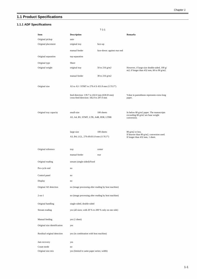
1.1.1 ADF Specifications0013-3451
T-1-1
Item Description Remarks
Original pickup auto
Original placement original tray face-up
manual feeder face-down: against rear end
Original separation top separation
Original type Sheet
Original weight original tray 50 to 216 g/m2 However, if large-size double-sided, 100 g/m2; if longer than 432 mm, 60 to 90 g/m2.
manual feeder 38 to 216 g/m2
Original size A5 to A3 / STMT to 279.4 X 431.8 mm (11'X17')
feed direction: 139.7 to 432.0 mm (630.l0 mm)cross-feed direction: 182.0 to 297.0 mm
Value in parentheses represents extra-long paper.
Original tray capacity small-size 100 sheets In below 80 g/m2 paper. The manuscripts exceeding 80 g/m2 are base weight conversion.A5, A4, B5, STMT, LTR, A4R, B5R, LTRR
large-size 100 sheets 80 g/m2 or less.If heavier than 80 g/m2, conversion used.If longer than 432 mm, 1 sheet.A3, B4, LGL, 279.4X431.8 mm (11'X17')
Original reference tray center
manual feeder rear
Original reading stream (single-sided)/fixed
Pre-cycle end no
Control panel no
Display no
Original AE detection no (image processing after reading by host machine)
2-on-1 no (image processing after reading by host machine)
Original handling single-sided, double-sided
Stream reading yes (all sizes; with 20 % to 200 % only on one side)
Manual feeding yes (1 sheet)
Original size identification yes
Residual original detection yes (in combination with host machine)
Jam recovery yes
Count mode no
Original size mix yes (limited to same paper series; width)
Chapter 1
1-2
The above information is subject to change for product revision.
1.2 Names of Parts
1.2.1 External View0013-3452
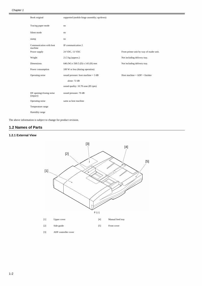
F-1-1
Book original supported (mobile hinge assembly; up/down)
Tracing paper mode no
Silent mode no
stamp no
Communication with host machine
IP communication 2
Power supply 24 VDC, 13 VDC From printer unit by way of reader unit.
Weight 21.5 kg (approx.) Not including delivery tray.
Dimensions 646 (W) x 569.5 (D) x 143 (H) mm Not including delivery tray.
Power consumption 100 W or less (during operation)
Operating noise sound pressure: host machine + 3 dB Host machine + ADF + finisher
alone: 72 dB
sound quality: 10.78 sone (85 ipm)
DF opening/closing noise (impact)
sound pressure: 70 dB
Operating noise same as host machine
Temperature range
Humidity range
[1] Upper cover [4] Manual feed tray
[2] Side guide [5] Front cover
[3] ADF controller cover
[1]
[2]
[3][4]
[5]

Chapter 1
1-3
1.2.2 Cross Section0013-3453
F-1-2
1.3 Using the Machine
1.3.1 Original Set Indicator0013-3454
The Original Set Indicator [1] goes on when an original is placed on the original tray, and flashes when a jam occurs.
F-1-3-Warnings and Action to TakeIf the Original Set indicator starts to flash while an original is inside the DADF, suspect a jam; go through the following to remove the jam:1) Remove all originals from the original tray.
2) Open the upper cover, and remove the jam, if found.3) Open the DADF, and remove the original from the copyboard glass, if found.4) Put the originals back into initial sequence, and place the stack in the DADF.
[1] Reversing roller B member [13] Delivery roller B member
[2] Reversing roller B [14] Delivery roller
[3] Reversing flapper [15] Delivery guide flapper
[4] Registration pressure roller [16] Feeding belt
[5] Registration roller [17] Stopper plate
[6] Pull-off roller [18] Separation belt
[7] Pull-off pressure roller [19] Feed belt driver roller
[8] Feeding roller [20] Guide flapper
[9] Pickup roller [21] Pre-reversal flapper
[10] Manual feed registration roller [22] Reversing roller A
[11] Manual feed stopper plate [23] Reversing roller A member
[12] elivery roller A member
[1] [2] [3] [4] [5] [6] [7] [8] [9] [10] [11] [12]
[15] [14] [13][16][18] [17][19][20][21][23] [22]


Chapter 2 Installation


Contents
Contents
2.1 Unpacking and Checking the Components ....................................................................................................................2-12.1.1 Points to Note About Installation................................................................................................................................................. 2-12.1.2 Checking the Contents (DADF-R1)............................................................................................................................................. 2-12.1.3 Checking the Contents (Power Supply Unit-S1) ......................................................................................................................... 2-1
2.2 Installation Procedure ....................................................................................................................................................2-22.2.1 Turning Off the Host Machine (imagePRESS C1 Series) ........................................................................................................... 2-22.2.2 Points to Note When Turning ON/OFF the power of Host Machine (imagePRESS C7000Series)............................................ 2-22.2.3 Installing the DADF-R1 (imagePRESS C1 Series) ..................................................................................................................... 2-32.2.4 Installing the DADF-R1 (imagePRESS C7000Series) ................................................................................................................ 2-62.2.5 Installing the Option Power Supply Unit-S1 (imagePRESS C1 Series).................................................................................... 2-10
2.3 Making Adjustments ....................................................................................................................................................2-122.3.1 Adjustment (imagePRESS C1Series, imagePRESS C7000Series) ........................................................................................... 2-122.3.2 Adjusting the Right Angle (imagePRESS C1Series, imagePRESS C7000Series)................................................................... 2-122.3.3 Horizontal Registration Adjustment (imagePRESS C1Series, imagePRESS C7000Series).................................................... 2-132.3.4 Leading Edge Registration Adjustment (imagePRESS C1Series, imagePRESS C7000Series) .............................................. 2-142.3.5 Horizontal Registration Adjustment (Fine Adjustment) (imagePRESS C1Series, imagePRESS C7000Series) ...................... 2-172.3.6 Leading Edge Registration Adjustment (Fine Adjustment for Both Sides) (imagePRESS C1Series, imagePRESS C7000Series).
2-182.4 Attaching the Labels etc...............................................................................................................................................2-18
2.4.1 Attaching the Cleaning Instructions Label (imagePRESS C1Series, imagePRESS C7000Series).......................................... 2-182.4.2 Attaching the Manual Feeder Placement Label (imagePRESS C1Series, imagePRESS C7000Series) .................................. 2-18

Chapter 2
2-1
2.1 Unpacking and Checking the Components
2.1.1 Points to Note About Installation0014-6095
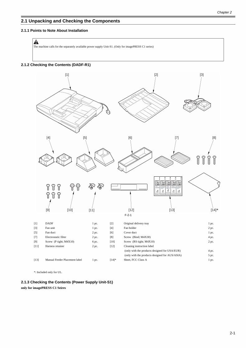
2.1.2 Checking the Contents (DADF-R1)0014-2693
F-2-1
2.1.3 Checking the Contents (Power Supply Unit-S1)0013-0957
only for imagePRESS C1 Seires
The machine calls for the separately available power supply Unit-S1. (Only for imagePRESS C1 series)
[1] DADF 1 pc. [2] Original delivery tray 1 pc.[3] Fan unit 1 pc. [4] Fan holder 2 pc.[5] Fan duct 2 pc. [6] Cover duct 1 pc.[7] Electrostatic filter 2 pc. [8] Screw (Bind; M4X30) 4 pc.[9] Screw (P tight; M4X10) 6 pc. [10] Screw (RS tight; M4X10) 2 pc.[11] Harness retainer 2 pc. [12] Cleaning instruction label
(only with the products designed for USA/EUR) 4 pc. (only with the products designed for AUS/ASIA) 5 pc.
[13] Manual Feeder Placement label 1 pc. [14]* Sheet, FCC Class A 1 pc.
*: Included only for UL.
[1] [2] [3]
[4] [5] [6] [7] [8]
[9] [12][10] [13] [14][11]

Chapter 2
2-2
F-2-2
2.2 Installation Procedure
2.2.1 Turning Off the Host Machine (imagePRESS C1 Series)
0013-5068
2.2.2 Points to Note When Turning ON/OFF the power of Host Machine (imagePRESS C7000Series)
0016-3369
[2] [3] [[4]
[1] Power Supply unit 1 pc. [2] Screw (Bind; M4X6) 4 pc.[3] Fan relay cable 1 pc. [4] DC relay cable 1 pc.[5] AC relay cable 1 pc. [6]* Ferrite core 1 pc.* The parts is only for the 200V machine.
Turning Off the Main PowerBe sure to go through the following steps when turning off the main power to protect the machine's hard disk:1) Hold down the control panel power switch for 3 sec or more.2) Follow the shut-down instructions on the screen. (The main power will go off automatically.)3) Disconnect the 2 power plugs of the machine (1 at the for the rear, 1 at the left side).
Power-On Order for Turning On the Power When Pickup/Delivery Accessories are ConnectedBe sure to turn on the power in the correct order otherwise it may cause an error because the host machine fails to recognize accessories including this equipment.
<Power-On Order>1) Accessories2) Host machineMEMO:There is no power-on order among accessories
Points to Note When Turning Off the Main Power of the Host MachineBe sure to turn off the main power in the following order to protect hard disk of the host machine.1) Press the power switch on control panel for 3 sec or more.2) Follow the instruction on the shutdown sequence screen (the main power switch will go off automatically).3) Turn off the breaker.4) Disconnect the power plug.
Chapter 2
2-3
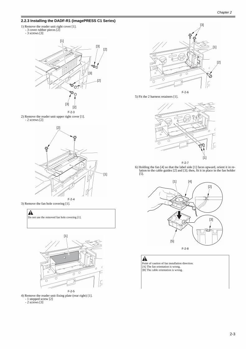
2.2.3 Installing the DADF-R1 (imagePRESS C1 Series)0013-0864
1) Remove the reader unit right cover [1].- 3 cover rubber pieces [2]- 3 screws [3]
F-2-32) Remove the reader unit upper right cover [1].
- 2 screws [2]
F-2-43) Remove the fan hole covering [1].
F-2-54) Remove the reader unit fixing plate (rear right) [1].
- 1 stepped screw [2]- 2 screws [3]
F-2-65) Fit the 2 harness retainers [1].
F-2-76) Holding the fan [4] so that the label side [1] faces upward, orient it in re-
lation to the cable guides [2] and [3]; then, fit it in place in the fan holder[5].
F-2-8
Do not use the removed fan hole covering [1].
[1]
[2]
[2]
[2]
[3]
[3]
[3]
[2]
[1]
[1]
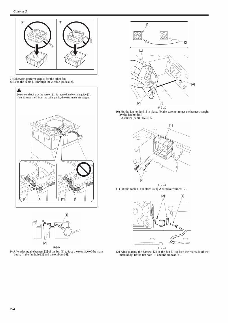
Point of caution of fan installation direction.[A] The fan orientation is wrong.[B] The cable orientation is wrong.
[1]
[2]
[3]
[1]
[1] [4]
[5]
[2]
[3]
Chapter 2
2-4
7) Likewise, perform step 6) for the other fan.8) Lead the cable [1] through the 2 cable guides [2].
F-2-99) After placing the harness [2] of the fun [1] to face the rear side of the main
body, fit the fan hole [3] and the emboss [4].
F-2-1010) Fix the fan holder [1] in place. (Make sure not to get the harness caught
by the fan holder.)- 2 screws (Bind; 4X30) [2]
F-2-1111) Fix the cable [1] in place using 2 harness retainers [2].
F-2-1212) After placing the harness [2] of the fun [1] to face the rear side of the
main body, fit the fan hole [3] and the emboss [4].
Be sure to check that the harness [1] is secured in the cable guide [2].If the harness is off from the cable guide, the wire might get caught.
[A] [B]
[2] [1] [2] [1]
[1]
[2]
[1]
[1]
[2] [3]
[4]
[1]
[2]
[1][2]
Chapter 2
2-5
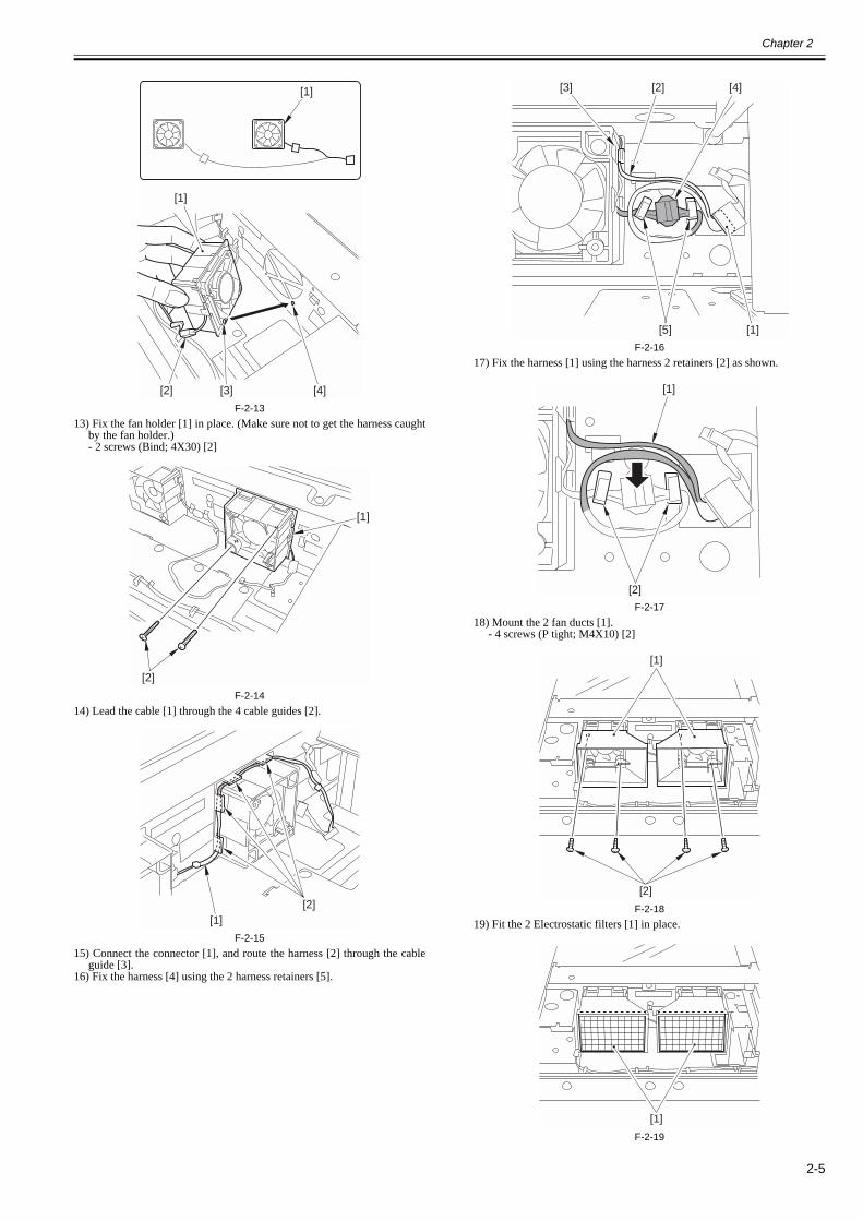
F-2-1313) Fix the fan holder [1] in place. (Make sure not to get the harness caught
by the fan holder.)- 2 screws (Bind; 4X30) [2]
F-2-1414) Lead the cable [1] through the 4 cable guides [2].
F-2-1515) Connect the connector [1], and route the harness [2] through the cable
guide [3].16) Fix the harness [4] using the 2 harness retainers [5].
F-2-1617) Fix the harness [1] using the harness 2 retainers [2] as shown.
F-2-1718) Mount the 2 fan ducts [1].
- 4 screws (P tight; M4X10) [2]
F-2-1819) Fit the 2 Electrostatic filters [1] in place.
F-2-19
[1]
[2] [3] [4]
[1]
[1]
[2]
[1][2]
[5] [1]
[2] [4][3]
[2]
[1]
[1]
[2]
[1]

Chapter 2
2-6
20) Mount the cover duct [1] to the reader unit right cover.- 2 screws (P tight; M4X10) [2]
F-2-2021) Attach the parts, which have been detached at the previous steps.
- reader unit fixing plate (rear right)- reader unit upper right cover- reader unit right cover
22) Mount the Original delivery tray [1].- 2 screws (RS tight; M4X10) [2]
F-2-2123) Lift the DADF [1] to fit it into the reader unit.
F-2-2224) Fit the cable [1] of the DADF to the host machine.
F-2-2325) Close the DADF.
2.2.4 Installing the DADF-R1 (imagePRESS C7000Series)0016-3327
1) Detach the sub station upper right cover [1].- 3 screws [2]
F-2-242) Detach the reader right cover [1].
- 3 screws [2]
F-2-253) Detach the reader upper right cover [1].
- 2 screws [2]
Be careful not to pinch your hands between the DADF and the host machine.
[1]
[2]
[1]
[2]
[1]
MEMO:When installing this equipment together with the reader, start the procedure from step 5.
[1]
[1]
[2]
[1]
[2]
[2]
[2]
Chapter 2
2-7
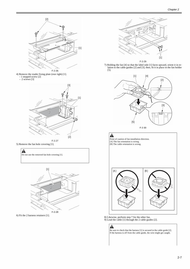
F-2-264) Remove the reader fixing plate (rear right) [1].
- 1 stepped screw [2]- 2 screws [3]
F-2-275) Remove the fan hole covering [1].
F-2-286) Fit the 2 harness retainers [1].
F-2-297) Holding the fan [4] so that the label side [1] faces upward, orient it in re-
lation to the cable guides [2] and [3]; then, fit it in place in the fan holder[5].
F-2-30
8) Likewise, perform step 7 for the other fan.9) Lead the cable [1] through the 2 cable guides [2].
Do not use the removed fan hole covering [1].
[1]
[2]
[1]
[2]
[3]
[1]
Point of caution of fan installation direction.[A] The fan orientation is wrong.[B] The cable orientation is wrong.
Be sure to check that the harness [1] is secured in the cable guide [2].If the harness is off from the cable guide, the wire might get caught.
[1]
[1] [4]
[5]
[2]
[3]
[A] [B]
Chapter 2
2-8
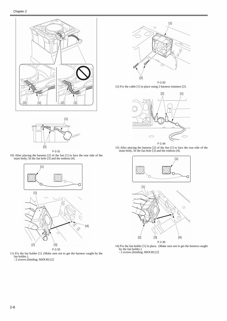
F-2-3110) After placing the harness [2] of the fun [1] to face the rear side of the
main body, fit the fan hole [3] and the emboss [4].
F-2-3211) Fix the fan holder [1]. (Make sure not to get the harness caught by the
fan holder.)- 2 screws (binding; M4X30) [2]
F-2-3312) Fix the cable [1] in place using 2 harness retainers [2].
F-2-3413) After placing the harness [2] of the fun [1] to face the rear side of the
main body, fit the fan hole [3] and the emboss [4].
F-2-3514) Fix the fan holder [1] in place. (Make sure not to get the harness caught
by the fan holder.)- 2 screws (binding; M4X30) [2]
[2] [1] [2] [1]
[1]
[2]
[1]
[1]
[2] [3]
[4]
[1]
[2]
[1][2]
[1]
[2] [3] [4]
[1]

Chapter 2
2-9
F-2-3615) Route the cable [1] through the cable guides [2] of the fan holder.
F-2-3716) Connect the connector [1] and route the harness [2] through the cable
guide [3].17) Fix the harness [4] using the 2 harness retainers [5].
F-2-3818) Fix the harness [1] using the harness 2 retainers [2] as shown.
F-2-39
19) Mount the 2 fan ducts [1].- 4 screws (P tight; M4X10) [2]
F-2-4020) Fit the 2 Electrostatic filters [1] in place.
F-2-4121) Go back to step 23 in Color Image Reader-H1 Installation Procedure.22) Mount the cover duct [1] to the reader right cover.
- 2 screws (P tightening; M4X10) [2]
F-2-4223) Attach the detached parts.
- Reader fixing plate (rear right)- Reader upper right cover- Reader right cover
24) Mount the document delivery tray [1].- 2 screws (RS tight; M4X10) [2]
[1]
[2]
[1][2]
[5] [1]
[2] [4][3]
[2]
[1]
[1]
[2]
[1]
[1]
[2]

Chapter 2
2-10
F-2-4325) Attach the sub station upper right cover [1].26) Lift the DADF [1] to fit it into the reader unit.
F-2-4427) Close the DADF.28) Fit the cable [1] of the DADF to the host machine.
F-2-4529) Remove all the tapes which are affixed to the equipment.
2.2.5 Installing the Option Power Supply Unit-S1 (imagePRESS C1 Series)
0013-0952
1) Open the decurler front cover [1].
F-2-462) Open the decurler upper unit [1].
F-2-473) Move the outer delivery roller cover [1] in the direction of the arrow to
detach it.- 1 screws [2]
F-2-484) Removing the delivery tray.5) Remove the lower left cover [1].
- 2 face covers [2]- 3 screws [3]
F-2-496) Disconnect the connector [1] and the 2 reuse bands [2].
Be careful not to pinch your hands between the DADF and the host machine.
[1]
[2]
[1]
[1]
[1]
[1]
[1]
[2]
[2]
[3] [1]
[3]
Chapter 2
2-11
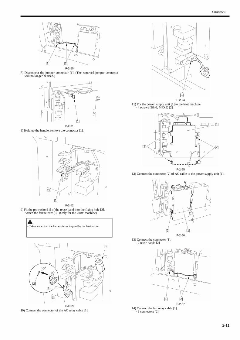
F-2-507) Disconnect the jumper connector [1]. (The removed jumper connector
will no longer be used.)
F-2-518) Hold up the handle, remove the connector [1].
F-2-529) Fit the protrusion [1] of the reuse band into the fixing hole [2].
Attach the ferrite core [3]. (Only for the 200V machine)
F-2-5310) Connect the connector of the AC relay cable [1].
F-2-5411) Fix the power supply unit [1] to the host machine.
- 4 screws (Bind; M4X6) [2]
F-2-5512) Connect the connector [2] of AC cable to the power supply unit [1].
F-2-5613) Connect the connector [1].
- 2 reuse bands [2]
F-2-5714) Connect the fan relay cable [1].
- 3 connectors [2]
- Take care so that the harness is not trapped by the ferrite core.
[1] [2]
[1]
[1]
[1][2]
[3]
[1]
[1]
[2] [2]
[2] [1]
[1] [2]
Chapter 2
2-12
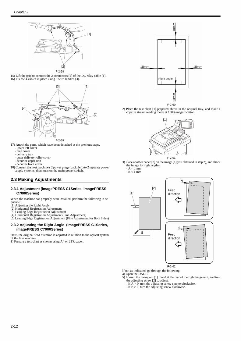
F-2-5815) Lift the grip to connect the 2 connectors [2] of the DC relay cable [1].16) Fix the 4 cables in place using 3 wire saddles [3].
F-2-5917) Attach the parts, which have been detached at the previous steps.
- lower left cover- face cover- delivery tray- outer delivery roller cover- decurler upper unit- decurler front cover
18) Connect the host machine's 2 power plugs (back, left) to 2 separate powersupply systems; then, turn on the main power switch.
2.3 Making Adjustments
2.3.1 Adjustment (imagePRESS C1Series, imagePRESS C7000Series)
0013-0255
When the machine has properly been installed, perform the following in se-quence:[1] Adjusting the Right Angle[2] Horizontal Registration Adjustment[3] Leading Edge Registration Adjustment[4] Horizontal Registration Adjustment (Fine Adjustment)[5] Leading Edge Registration Adjustment (Fine Adjustment for Both Sides)
2.3.2 Adjusting the Right Angle (imagePRESS C1Series, imagePRESS C7000Series)
0013-0259
Here, the original feed direction is adjusted in relation to the optical systemof the host machine.1) Prepare a test chart as shown using A4 or LTR paper.
F-2-602) Place the test chart [1] prepared above in the original tray, and make a
copy in stream reading mode at 100% magnification.
F-2-613) Place another paper [2] on the image [1] you obtained in step 2), and check
the image for right angles.- A < 1 mm- B < 1 mm
F-2-62If not as indicated, go through the following:4) Open the DADF.5) Loosen the fixing nut [1] found at the rear of the right hinge unit, and turn
the adjusting screw [2] to adjust.- If A > 0, turn the adjusting screw counterclockwise.- If B > 0, turn the adjusting screw clockwise.
[1]
[2]
[2]
[3] [1]
[2]
Right angle
10mm10mm
10m
m10
mm
[1]
A
Feeddirection
Feeddirection
B
[1]
[2]
Chapter 2
2-13
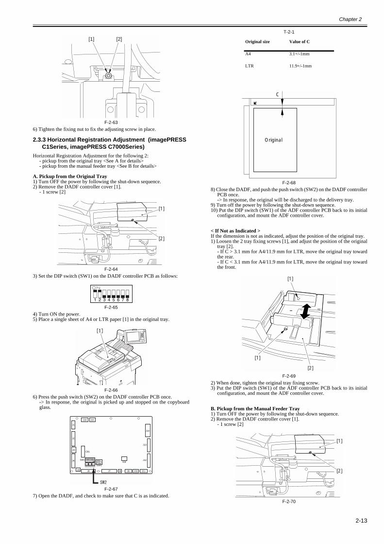
F-2-636) Tighten the fixing nut to fix the adjusting screw in place.
2.3.3 Horizontal Registration Adjustment (imagePRESS C1Series, imagePRESS C7000Series)
0013-0256
Horizontal Registration Adjustment for the following 2:- pickup from the original tray <See A for details>- pickup from the manual feeder tray <See B for details>
A. Pickup from the Original Tray1) Turn OFF the power by following the shut-down sequence. 2) Remove the DADF controller cover [1].
- 1 screw [2]
F-2-643) Set the DIP switch (SW1) on the DADF controller PCB as follows:
F-2-654) Turn ON the power.5) Place a single sheet of A4 or LTR paper [1] in the original tray.
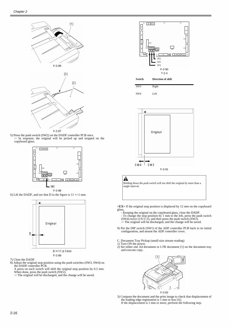
F-2-666) Press the push switch (SW2) on the DADF controller PCB once.
-> In response, the original is picked up and stopped on the copyboardglass.
F-2-677) Open the DADF, and check to make sure that C is as indicated.
T-2-1
F-2-688) Close the DADF, and push the push switch (SW2) on the DADF controller
PCB once.-> In response, the original will be discharged to the delivery tray.
9) Turn off the power by following the shut-down sequence.10) Put the DIP switch (SW1) of the ADF controller PCB back to its initial
configuration, and mount the ADF controller cover.
< If Not as Indicated >If the dimension is not as indicated, adjust the position of the original tray.1) Loosen the 2 tray fixing screws [1], and adjust the position of the original
tray [2].- If C > 3.1 mm for A4/11.9 mm for LTR, move the original tray towardthe rear.- If C < 3.1 mm for A4/11.9 mm for LTR, move the original tray towardthe front.
F-2-692) When done, tighten the original tray fixing screw.3) Put the DIP switch (SW1) of the ADF controller PCB back to its initial
configuration, and mount the ADF controller cover.
B. Pickup from the Manual Feeder Tray1) Turn OFF the power by following the shut-down sequence. 2) Remove the DADF controller cover [1].
- 1 screw [2]
F-2-70
[2][1]
[2]
[1]
J1
J2
J5
J3 J6 J7 J8 J9 J10
J16 J15
J11
J14
IC8
J13
J12
J4CB1
SW1
DSP1SW4SW3SW2
Original size Value of C
A4 3.1+/-1mm
LTR 11.9+/-1mm
C
Original
[1]
[2]
[1]
[2]
[1]

Chapter 2
2-14
3) Set the DIP switch (SW1) of the DADF controller PCB as shown.
F-2-714) Turn ON the power.5) Open the manual feed tray [1], and set A4 or LTR paper [2] in it.
6) But the paper [2] against the rear side [3] of the manual feed tray.
F-2-72
F-2-737) Press the push switch (SW2) on the DADF controller PCB once.
-> In response, the original will be picked up and stopped on thecopyboard glass.
F-2-748) Open the DADF, and check to see that C in the figure is as indicated.
T-2-2
F-2-759) Close the DADF, and press the push switch (SW2) on the DADF control-
ler PCB once.-> In response, the original will be discharged to the delivery tray.
10) Turn OFF the power by following the shut-down sequence. 11) Put the DIP switch (SW1) on the DADF controller PCB back to its initial
configuration, and attach the DADF controller cover.
< If Not as Indicated >If the dimension is not as indicated, adjust the position of the manual feedertray.1) Loosen the manual feeder tray fixing screw [1], and adjust the manual
feeder tray [2].- If C > 3.1 mm, move the manual feeder tray toward the rear.- If C < 3.1 mm, move the manual feeder tray toward the front.
F-2-762) When done, tighten the manual feeder tray fixing screw.3) Put the DIP switch (SW1) on the DADF controller PCB back to its initial
configuration, and attach the DADF controller cover.
2.3.4 Leading Edge Registration Adjustment (imagePRESS C1Series, imagePRESS C7000Series)
0013-3698
Leading Edge Registration Adjustment for the following 3:- pickup from the original tray <See A for details>- pickup from the manual feeder tray <See B for details>- pickup from the original tray (small-size stream reading) <See C fordetails>
A. Pickup from the Original Tray1) Remove the DADF control cover [1].
- 1 screw [2]
F-2-772) Set the DIP switch (SW1) on the DADF controller PCB as follows:
Value of C
3.1+/-1mm
[1]
[2]
[3]
J1
J2
J5
J3 J6 J7 J8 J9 J10
J16 J15
J11
J14
IC8
J13
J12
J4CB1
SW1
DSP1SW4SW3SW2
C
Original
[1]
[2]
[2]
[1]
Chapter 2
2-15
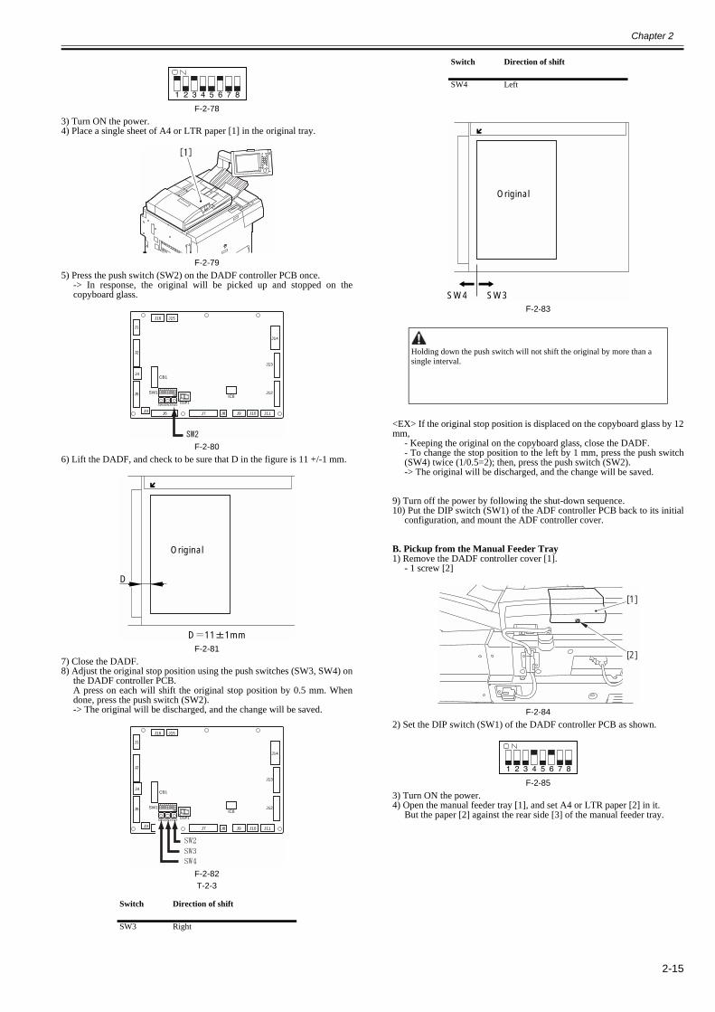
F-2-783) Turn ON the power.4) Place a single sheet of A4 or LTR paper [1] in the original tray.
F-2-795) Press the push switch (SW2) on the DADF controller PCB once.
-> In response, the original will be picked up and stopped on thecopyboard glass.
F-2-806) Lift the DADF, and check to be sure that D in the figure is 11 +/-1 mm.
F-2-817) Close the DADF.8) Adjust the original stop position using the push switches (SW3, SW4) on
the DADF controller PCB.A press on each will shift the original stop position by 0.5 mm. Whendone, press the push switch (SW2).-> The original will be discharged, and the change will be saved.
F-2-82T-2-3
F-2-83
<EX> If the original stop position is displaced on the copyboard glass by 12mm,
- Keeping the original on the copyboard glass, close the DADF.- To change the stop position to the left by 1 mm, press the push switch(SW4) twice (1/0.5=2); then, press the push switch (SW2).-> The original will be discharged, and the change will be saved.
9) Turn off the power by following the shut-down sequence.10) Put the DIP switch (SW1) of the ADF controller PCB back to its initial
configuration, and mount the ADF controller cover.
B. Pickup from the Manual Feeder Tray1) Remove the DADF controller cover [1].
- 1 screw [2]
F-2-842) Set the DIP switch (SW1) of the DADF controller PCB as shown.
F-2-853) Turn ON the power.4) Open the manual feeder tray [1], and set A4 or LTR paper [2] in it.
But the paper [2] against the rear side [3] of the manual feeder tray.
Switch Direction of shift
SW3 Right
J1
J2
J5
J3 J6 J7 J8 J9 J10
J16 J15
J11
J14
IC8
J13
J12
J4CB1
SW1
DSP1SW4SW3SW2
D
Original
D 11 1mm
J1
J2
J5
J3 J6 J7 J8 J9 J10
J16 J15
J11
J14
IC8
J13
J12
J4CB1
SW1
DSP1SW4SW3SW2
SW4 Left
Holding down the push switch will not shift the original by more than a single interval.
Switch Direction of shift
Original
SW3SW4
[2]
[1]
Chapter 2
2-16
F-2-86
F-2-875) Press the push switch (SW2) on the DADF controller PCB once.
-> In response, the original will be picked up and stopped on thecopyboard glass.
F-2-886) Lift the DADF, and see that D in the figure is 11 +/-1 mm.
F-2-897) Close the DADF.8) Adjust the original stop position using the push switches (SW3, SW4) on
the DADF controller PCB.A press on each switch will shift the original stop position by 0.5 mm.When done, press the push switch (SW2).-> The original will be discharged, and the change will be saved.
F-2-90T-2-4
F-2-91
<EX> If the original stop position is displaced by 12 mm on the copyboardglass,
- Keeping the original on the copyboard glass, close the DADF.- To change the stop position by 1 mm to the left, press the push switch(SW4) twice (1/0.5=2), and then press the push switch (SW2).-> The original will be discharged, and the change will be saved.
9) Put the DIP switch (SW1) of the ADF controller PCB back to its initialconfiguration, and mount the ADF controller cover.
C. Document Tray Pickup (small-size stream reading)1) Turn ON the power.2) Set either one A4 document or LTR document [1] on the document tray
and execute copy.
F-2-923) Compare the document and the print image to check that displacement of
the leading edge registration is 1 mm or less [A].If the displacement is 1 mm or more, perform the following step.
[1]
[2]
[3]
J1
J2
J5
J3 J6 J7 J8 J9 J10
J16 J15
J11
J14
IC8
J13
J12
J4CB1
SW1
DSP1SW4SW3SW2
D
Original
D 11 1mm
Switch Direction of shift
SW3 Right
SW4 Left
Holding down the push switch will not shift the original by more than a single interval.
J1
J2
J5
J3 J6 J7 J8 J9 J10
J16 J15
J11
J14
IC8
J13
J12
J4CB1
SW1
DSP1SW4SW3SW2
Original
SW3SW4

Chapter 2
2-17
F-2-934) Display the service mode (FEEDER > ADJUST > STRD-S) and change
the setting according to the displacement.This setting adjusts the value of the leading edge registration for thedocument tray pickup.- Setting range: -7 to 7- 1 unit: 0.5 mm
When the value is set larger, the margin is made smaller. When the valueis set smaller, the margin is made larger.
F-2-945) Press the OK key.6) Exit from the service mode.7) Set either one A4 document or LTR document on the document tray and
execute copy.8) Compare the document and the print image to check that displacement of
the leading edge registration is 1 mm or less.
2.3.5 Horizontal Registration Adjustment (Fine Adjustment) (imagePRESS C1Series, imagePRESS C7000Series)
0013-0257
This adjustment is normally unnecessary at the time of installation. In thecase that the customer needs the adjustment with high accuracy, perform thefollowing step.The horizontal registration adjustment (fine adjustment) is executed to thefollowing 2 occasions.
- Document tray pickup <See A for details>- Manual feed tray pickup <See B for details>
When executing this adjustment, use the service mode.The adjustment value is stored in the DADF controller PCB.
A. Document Tray Pickup1) Turn ON the power.2) Set either one A4 document or LTR document [1] on the document tray
and execute copy.
F-2-953) Compare the document and the print image to check that displacement of
the horizontal registration is 1 mm or less [A].If the displacement is 1 mm or more, perform the following step.
F-2-96
4) Display the service mode (COPIER > ADJUST > ADJ-XY > ADJ-Y-DF)and change the setting according to the displacement.This setting adjusts the value of the horizontal registration for thedocument tray pickup.- Setting range: 1 to 211- 1 unit: 0.1 mm
When the value is set larger, the margin is made smaller. When the valueis set smaller, the margin is made larger.
F-2-975) Press the OK key.6) Exit from the service mode.7) Set either one A4 document or LTR document on the document tray and
execute copy.8) Compare the document and the print image to check that displacement of
the horizontal registration is 1 mm or less.9) Execute horizontal registration adjustment for the large size paper (A3 or
LGR) as well.Be sure to use the following Service Mode:COPIER > ADJUST > ADJ-XY > ADJ-Y-FX
B. Manual Feed Tray Pickup1) Set either one A4 document or LTR document [2] on the manual feed tray
[1].Insert the document to the rear end [3].
F-2-98
F-2-992) For the subsequent procedure, follow 'A. Document Tray Pickup'.
Be sure to use the following Service Mode:COPIER > ADJUST > ADJ-XY > ADJ-Y-FX
Feeding direction
Set the value larger Set the value smaller
Print image
MEMO:See 'A. Document Tray Pickup'.
Feeding direction
Set the value larger
Set the value smaller
Print image
[1]
[2]
[3]

Chapter 2
2-18
2.3.6 Leading Edge Registration Adjustment (Fine Adjustment for Both Sides) (imagePRESS C1Series, imagePRESS C7000Series)
0015-3389
This adjustment is normally unnecessary at the time of installation. In thecase that the customer needs the adjustment with high accuracy, perform thefollowing step.The leading edge registration adjustment (Fine Adjustment for Both Sides)is executed to the following 2 occasions.
- Document tray pickup (the 1st side) <See A for details>- Document tray pickup (the 2nd side) <See B for details>
When executing this adjustment, use the service mode.The adjustment value is stored in the DADF controller PCB.A. Document Tray Pickup (the 1st side)1) Set either one A4 document or LTR document [1] on the document tray
and execute double-sided copy.
F-2-1002) The following operation is the same as "C. Document Tray Pickup (small
size, stream reading)".Be sure to use the following Service Mode:FEEDER > ADJUST > DOCST
B. Document Tray Pickup (the 2nd side)The operation is the same as "A. Document Tray Pickup (1st-side of the du-
plex print)".The following 2 notes are different from the operation above.- Set the document on the manual feed tray.- The following Service Mode should be used:FEEDER > ADJUST > DOCST-M
2.4 Attaching the Labels etc.
2.4.1 Attaching the Cleaning Instructions Label (imagePRESS C1Series, imagePRESS C7000Series)
0013-1542
1) Position the cleaning instructions label [1] on the upper rear cover asshown, and attach it.(Be sure to select the correct language.)
F-2-101
2.4.2 Attaching the Manual Feeder Placement Label (imagePRESS C1Series, imagePRESS C7000Series)
0013-1545
1) Open the manual feeder [1] of the DADF, and position and attach the man-ual feeder placement label [2]. (Be sure to select the correct language.)
F-2-102
1mm
1mm
[1]
[2]
[1]

Chapter 3 Functions


Contents
Contents
3.1 Basic Construction .........................................................................................................................................................3-13.1.1 Overview of Electrical Circuit ..................................................................................................................................................... 3-13.1.2 Inputs to ADF Controller PCB .................................................................................................................................................... 3-23.1.3 Outputs from ADF Controller PCB ............................................................................................................................................. 3-4
3.2 Basic Operation..............................................................................................................................................................3-43.2.1 Outline.......................................................................................................................................................................................... 3-43.2.2 Outline.......................................................................................................................................................................................... 3-63.2.3 CW Pickup/Delivery .................................................................................................................................................................... 3-63.2.4 Pre-Reversal/Reversal/Delivery................................................................................................................................................... 3-73.2.5 Manual Feeder Pickup/Delivery .................................................................................................................................................. 3-8
3.3 Document Detection ......................................................................................................................................................3-93.3.1 Outline.......................................................................................................................................................................................... 3-93.3.2 Detecting the Presence/Absence of an Original........................................................................................................................... 3-93.3.3 Original Size Detection 1........................................................................................................................................................... 3-103.3.4 Original Size Detection 2........................................................................................................................................................... 3-113.3.5 Detecting the Presence/Absence of an Original in the Manual Feeder...................................................................................... 3-14
3.4 Document Pickup/Separation.......................................................................................................................................3-153.4.1 Outline........................................................................................................................................................................................ 3-153.4.2 Moving Up/Down the Pickup Roller Unit ................................................................................................................................. 3-153.4.3 Switching the Separation Pressure............................................................................................................................................. 3-173.4.4 Separation Sensor (S4) and Skew Sensor (S5) .......................................................................................................................... 3-183.4.5 Controlling the Pickup Motor (M3)........................................................................................................................................... 3-193.4.6 Controlling the Separation Motor (M4) ..................................................................................................................................... 3-193.4.7 Sequence of Operations ............................................................................................................................................................. 3-20
3.5 Document Feeding/Delivery ........................................................................................................................................3-203.5.1 Outline........................................................................................................................................................................................ 3-203.5.2 Controlling the Belt Motor (M2) ............................................................................................................................................... 3-213.5.3 Controlling the Delivery Motor (M5) ........................................................................................................................................ 3-22
3.6 Feeding Unit.................................................................................................................................................................3-223.6.1 Outline of CW Pickup/Delivery................................................................................................................................................. 3-223.6.2 CW Pickup/Delivery Fixed Reading ......................................................................................................................................... 3-233.6.3 CW Pickup/Delivery (stream reading) ...................................................................................................................................... 3-263.6.4 Double-Sided Originals (fixed reading) .................................................................................................................................... 3-303.6.5 Fixed Reading (continuous; double-sided original)................................................................................................................... 3-343.6.6 Controlling the Reversal Motor (M1) ........................................................................................................................................ 3-383.6.7 Manual Feeder Pickup/Delivery Operation ............................................................................................................................... 3-39
3.7 Detecting Jams .............................................................................................................................................................3-403.7.1 Overview ................................................................................................................................................................................... 3-403.7.2 List of Jam Code ........................................................................................................................................................................ 3-413.7.3 Alarm Code ................................................................................................................................................................................ 3-44
3.8 Power Supply ...............................................................................................................................................................3-443.8.1 Overview.................................................................................................................................................................................... 3-44


Chapter 3
3-1
3.1 Basic Construction
3.1.1 Overview of Electrical Circuit0013-3455
The machine's electrical mechanisms are controlled by the ADF controller PCB (microcomputer CPU). The CPU interprets signals from sensors and the host ma-chine, and generates appropriate signals to drive such loads as motors and solenoids at such times as programmed in advance.
F-3-1
CPU(Q1)
ROM(IC1)
EEPROM(IC2)
RAM(Q4)
D/A(Q9)
IPC(Q2)
+5V +24V +5R+24R
Power supply PCB
Copier
Solenoid
Clutch
OriginalindicatorLED PCB
Sub tray PCB
Reversalmotor
driver PCB
Belt motordriver PCB
Motor
Sensor
Motor
Motor
ADF controller PCB
DC5V(Q65)
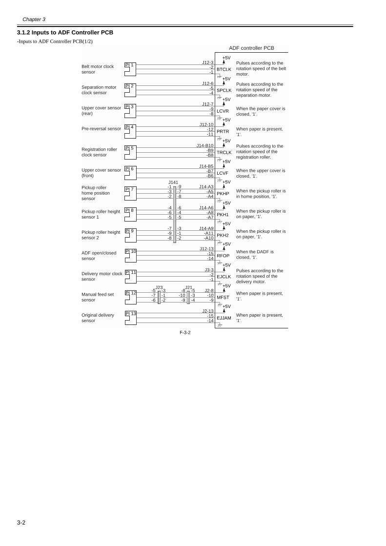
Chapter 3
3-2
3.1.2 Inputs to ADF Controller PCB0013-3456
-Inputs to ADF Controller PCB(1/2)
F-3-2
+5V
PI 1BTCLK
J12-3-2-1
+5V
PI 2SPCLK
J12-6-5-4
+5V
PI 3LCVR
J12-7-9-8
+5V
PI 4PRTR
J12-10-12-11
+5V
PI 5TRCLK
J14-B10-B9-B8
+5V
PI 6LCVF
J14-B5-B7-B6
+5V
PI 7PKHP
J14-A3-A5-A4
-9-7-8
+5V
PI 8PKH1
J14-A6-A8-A7
-6-4-5
+5V
PI 9PKH2
J14-A9-A11-A10
-3-1-2
-1-3-2
-4-6-5
-7-9-8
+5V
PI 10RFOP
J12-13-15-14
+5V
PI 11EJCLK
J2-13-15-14
+5V
PI 12MFST
J2-8-10
-9
-5-3-4
-8-10
-9
-3-1-2
-5-7-6
J141
J21J23
+5V
PI 13EJJAM
J3-3-2-1
Pulses according to therotation speed of the beltmotor.
Pulses according to therotation speed of theseparation motor.
When the paper cover isclosed, '1'.
When paper is present,'1'.
Pulses according to therotation speed of theregistration roller.
When the upper cover isclosed, '1'.
When the pickup roller isin home position, '1'.
When the pickup roller ison paper, '1'.
When the pickup roller ison paper, '1'.
When the DADF isclosed, '1'.
Pulses according to therotation speed of thedelivery motor.
When paper is present,'1'.
Belt motor clocksensor
Separation motorclock sensor
Upper cover sensor(rear)
Pre-reversal sensor
Registration rollerclock sensor
Upper cover sensor(front)
Pickup rollerhome positionsensor
Pickup roller heightsensor 1
Pickup roller heightsensor 2
ADF open/closedsensor
Delivery motor clocksensor
Manual feed setsensor
Original deliverysensor
ADF controller PCB
When paper is present,'1'.
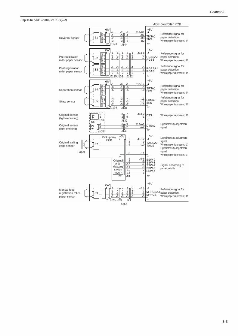
Chapter 3
3-3
-Inputs to ADF Controller PCB(2/2)
F-3-3
+5V+5V
TNSAJTNS
J14-B1-B4-B3-B2
-4-1-2-3
-2-5-4-3
-4-1-2-3
S1
+5V+5V
RGBSAJRGBS
J13-8-3-4S2
RGASAJRGAS
-5-6-7
-1-6-5
-4-3-2
-8-3-4
-5-6-7
-6-1-2
-3-4-5
-1-6-5
-4-3-2
-1-6-5
-4-3-2
S3
+5V+5V
SPSAJSPS
J13-14-9
-10S4
SKSAJSKS
DTS
DTSAJ
TAILSAJTAILS
SSW-0SSW-1SSW-2SSW-3SSW-4
-11-12-13
J13-2-1
-7-8
-2-1
-2-1
-3-2
-1-2
-2-1
-1-6-5
-4-3-2
-1-6-5
-4-3-2
-6-1-2
-3-4-5
S5
S6
+5V+5V
MFRGSAJMFRGS
J2-4-7-6-5
S9
+5V+5V
S7
J14-A1-A2
J5-12-9
-10
-11
J5-6-5-4-3-2-1
-2-5-4
-3
-8-9
-10-11-12-13
J144J149
J131J134
J132J136
J140J145
J133 J132J135
-9-6-7-8
-4-7-6-5
-1-4-3-2
-7-4-5-6
-4-1-2-3
J23 J21J25
SW301J51
Reference signal forpaper detectionWhen paper is present, '0'.
Paper
Reversal sensor
Pre-registrationroller paper sensor
Post registrationroller paper sensor
Separation sensor
Skew sensor
Original sensor(light-receiving)
Original sensor(light-emitting)
Original trailingedge sensor
Manual feedregistration rollerpaper sensor
ADF controller PCB
Reference signal forpaper detectionWhen paper is present, '0'.
Reference signal forpaper detectionWhen paper is present, '0'.
Reference signal forpaper detectionWhen paper is present, '0'.
Reference signal forpaper detectionWhen paper is present, '0'.
When paper is present, '0'.
Light intensity adjustmentsignal
Light intensity adjustmentsignalWhen paper is present, '1'.Light intensity adjustmentsignalWhen paper is present, '1'.
Signal according topaper width
Reference signal forpaper detectionWhen paper is present, '0'.
Pickup trayPCB
Originalwidth
detectingswitch
Com
para
tor
circ
uit
Com
para
tor
circ
uit
Com
para
tor
circ
uit
Com
para
tor
circ
uit
Com
para
tor
circ
uit

Chapter 3
3-4
3.1.3 Outputs from ADF Controller PCB0013-3458
-Outputs from ADF Controller PCB(1/1)
F-3-4
3.2 Basic Operation
3.2.1 Outline0013-3459
The DADF uses five motors and one clutch to pick up, separate, move, and deliver originals.
Name (notation) Description
Reversal motor (M1) Moves and reverses originals.
Belt motor (M2) Moves originals.
Pickup motor (M3) Moves up/down the pickup roller.
Separation motor (M4) Separates originals.
Delivery motor (M5) Delivers originals and picks up manually fed originals.
Separation clutch (CL) Turns on/off the pull-off roller and the separation/feed drive system.
+24V
CLD*J10-3
-4
+24V
SL1D*J9-1
-2
+24V
SL2D1*
SL2D2*
J9-3-4
-5
+24V
+24V
SL3D*J10-1
-2-2-1
-1-2
-2-1
-1-2
-2-1
-1-2
+24V
+24V+5V
SL4D1*
SL4D2*
M1OB*M1OA*M1OBM1OAT-Vref
EJMD*
SEPM+SEPM-
J2-1-2
-3
-12-11-10
-1-2-3
-3-2-1
-1-2-3
-3-2-1
-1-2-3
J6-8~10-1-2-3-4-5-6
-4~6-13-12-11-10
-9-8
-1-2-3-4-5-6
+24V+24V
AA*B
B*
-1-2-3-4-5-6
+24V+24V
AA*B
B*
-4~6-13-12-11-10
-9-8
M1
J8-1-2
-2-1
J2-11-12
-2-1
-2-1
-1-2
-11-12M5
M4
J24
J81
J21
FM1
J601J602
J21J22
J101
FAN(+24V)LOCK
J9-6-7-8
-3-2-1
-1-2-3J93
J92
J91
J102CL
SL1
SL2
SL3
SL4
+24V+5V
M2OB*M2OA*M2OBM2OAB-Vref
J7-8~10-1-2-3-4-5-6
M2
J71J72
Separation clutch
Reversal solenoid
Stopper plate solenoid(2-position)
Pre-reversal solenoid
Delivery solenoid(2-position)
Reversal motor
Belt motor
Pickup motor
Separation motor
Delivery motor
ADF controller PCB
When '0',the separation clutchgoes on.
When '0', the solenoidgoes on.
When '0', the solenoidgoes on. (position 1)When '0', the solenoidgoes on. (position 2)
When '0', the solenoidgoes on.
When '0', the solenoidgoes on. (position 1)When '0', the solenoidgoes on. (position 2)
For details,see Functions.
For details,see Functions.
For details,see Functions.
For details,see Functions.
For details,see Functions.
When '1', the fangoes on.When the fan isat rest, '1'.
Rev
ersa
l mot
erdr
iver
PC
BB
elt m
otor
driv
er P
CB
M3OAM3OA*M3OBM3OB*
J11-1-2-3-4
-1-2-3-4
M3
J111

Chapter 3
3-5
Diagram of Drive
F-3-5
PI 2
PI 1
PI 5
PI 11
SL3
SL1
SL2
SL4
M5
Pre
-rev
ersa
lsol
enoi
ddr
ive
sign
al(S
L1D
)
Sep
arat
ion
mot
orcl
ock
sign
al(S
PC
LK)
Sep
arat
ion
mot
ordr
ive
sign
al
Sep
arat
ion
clut
chdr
ive
sign
al(C
LD)
Sto
pper
sole
noid
driv
esi
gnal
2(S
L2D
2)
Sto
pper
plat
eso
leno
idsi
gnal
1(S
L2D
1)
Pic
kup
mot
ordr
ive
sign
al
Bel
tmot
ordr
ive
sign
alB
eltm
otor
cloc
ksi
gnal
(BT
CLK
)
Rev
ersa
lmot
ordr
ive
sign
al
Rev
ersa
lsol
enoi
ddr
ive
sign
al(S
L3D
)R
egis
trat
ion
rolle
rcl
ock
sign
al(T
RC
LK)
Del
iver
yso
leno
iddr
ive
sign
al1
(SL4
D)
Del
iver
ym
otor
driv
esi
gnal
Del
iver
ym
otor
cloc
ksi
gnal
(EJC
LK)
CL
Del
iver
yso
leno
iddr
ive
sign
al1
(SL4
D)
ADF controller PCB
M2
M3
M4
M1

Chapter 3
3-6
Sensor Arrangement
F-3-6
3.2.2 Outline0013-3460
The DADF operates in either of the following three modes; the DADF operates in response to instructions from the copier, executing appropriate modes to suit thecopier's operations.The following table shows each operation mode, an outline of its operation, and its corresponding copying mode:
T-3-1
3.2.3 CW Pickup/Delivery0013-3463
The following is an outline of the flow of originals.Pickup
F-3-7
No. Mode Operation Copying mode Copying operation
1 CW pickup/delivery Picks up an original, and delivers it as it is after copying.
Single-sided original to single-sided copy Signal-sided original to double-sided copy
Stream reading (fixed if the reproduction ratio is not between 50 % and 200 %)
2 Pre-reversal pickup/reversal/delivery
Reverses an original, picks it up, reverses it once again after copying, and delivers it. Fixed reading
Double-sided original to double-sided copyDouble-sided original to single-sided copy
Fixed reading
3 Manual feederpickup/delivery
Picks up an original from the manual feeder, and delivers it after copying.
Manual copy Fixed reading
PI4 PI7
PI6PI3
PI12SW301
S6 (light-emitting side)
PI8,PI9
S1
S2
S3
S7
S9
PI10 PI13
S6 (light-receiving side)
S4,S5
ADF controller PCB
Pre
-rev
ersa
l pap
er d
etec
tion
sign
al
Rev
ersa
l pap
er d
etec
tion
sign
al
Pos
t-re
gist
ratio
n ro
ller
pape
r de
tect
ion
sign
al
Pre
-reg
istr
atio
n ro
ller
pape
r de
tect
ion
sign
al
Sep
arat
ion
pape
r de
tect
ion
sign
al (
SP
S)/
Ske
w p
aper
det
ectio
n si
gnal
(S
KS
)
Pic
kup
rolle
r ho
me
posi
tion
sign
al
Pic
kup
rolle
r he
ight
1 s
igna
l/2 s
igna
l
Left
cove
r re
ar s
igna
l
Left
cove
r fr
ont s
igna
l
Orig
inal
sen
sor
light
em
issi
on s
igna
l
Orig
inal
det
ectio
n si
gnal
Orig
inal
pla
cem
ent i
ndic
atio
n lig
ht e
mis
sion
sig
nal
Orig
inal
wid
th d
etec
tion
sign
al
Orig
inal
trai
l edg
e de
tect
ion
sign
al
RF
ope
n/cl
osed
det
ectio
n si
gnal
Man
ual f
eede
r re
gist
ratio
n pa
per
dete
ctio
n si
gnal
Man
ual f
eede
r pl
acem
ent s
igna
l
Orig
inal
del
iver
y de
tect
ion
sign
al

Chapter 3
3-7
Scan
F-3-8Delivery
F-3-9
3.2.4 Pre-Reversal/Reversal/Delivery0013-3465
The following is an outline of the flow of originals:
F-3-10
Picking up
Pre-reversing
Feeding
Copyingthe 1st side
Moving
To next page

Chapter 3
3-8
F-3-11
3.2.5 Manual Feeder Pickup/Delivery0013-3466
The following is an outline of the flow of originals:
F-3-12
Reversing
Copyingthe 2nd side
Delivering
From previous page
Picking up
Stopping
Switching back
Copying
Delivering

Chapter 3
3-9
3.3 Document Detection
3.3.1 Outline0013-3467
The DADF is equipped with the following five types of mechanisms of detection:T-3-2
F-3-13
3.3.2 Detecting the Presence/Absence of an Original0013-3469
The presence/absence of an original in the original tray is detected by the original sensor (S6).When an original is placed on the original tray, the light from the light-emitting side of the original sensor is blocked, causing the light-receiving side of the originalsensor to send the original detection signal (DTS) to the ADF controller PCB, which in response turns on the Original Set indicator.
Item Description Sensor used (notation)
Presence/absence of an original Identifies the presence/absence of an original on the original tray. Original sensor (S6)
Original size 1 Identifies the size of the original placed in the original tray (as to beinglarge-size or small-size).
Original trailing edge sensor (S7)
Original size 2 Identifies the size of an original on the move (default size). Registration roller clock sensor (PI5)
Original in manual feeder Detects the presence/absence of an original in the manual feeder. Manual feeder set sensor (PI12)
S7
PI5
SW301
PI12
S6(light-emitting side)
S6(light-receiving side)
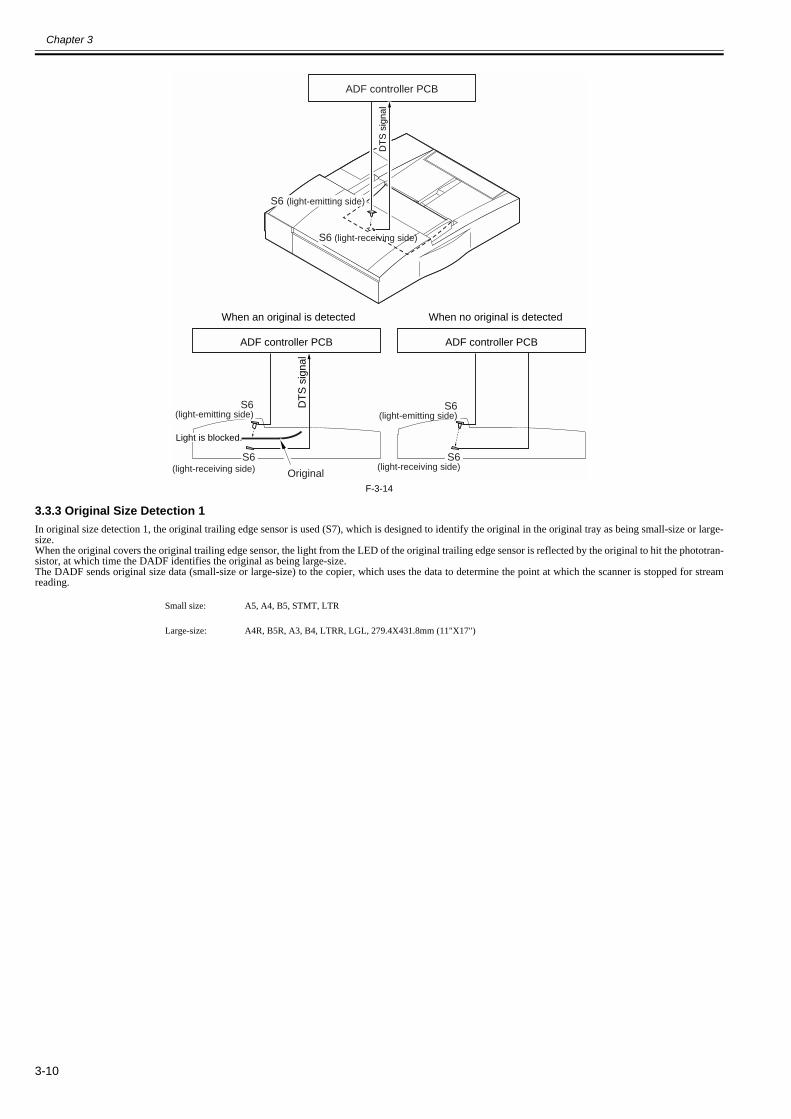
Chapter 3
3-10
F-3-14
3.3.3 Original Size Detection 10013-3470
In original size detection 1, the original trailing edge sensor is used (S7), which is designed to identify the original in the original tray as being small-size or large-size.When the original covers the original trailing edge sensor, the light from the LED of the original trailing edge sensor is reflected by the original to hit the phototran-sistor, at which time the DADF identifies the original as being large-size.The DADF sends original size data (small-size or large-size) to the copier, which uses the data to determine the point at which the scanner is stopped for streamreading.
Small size: A5, A4, B5, STMT, LTR
Large-size: A4R, B5R, A3, B4, LTRR, LGL, 279.4X431.8mm (11"X17")
ADF controller PCB
S6 (light-receiving side)
S6(light-emitting side)
S6(light-receiving side)
ADF controller PCB
When an original is detected When no original is detected
S6(light-emitting side)
S6(light-receiving side)
ADF controller PCB
DT
S s
igna
l
DT
S s
igna
l
Original
Light is blocked.
S6 (light-emitting side)
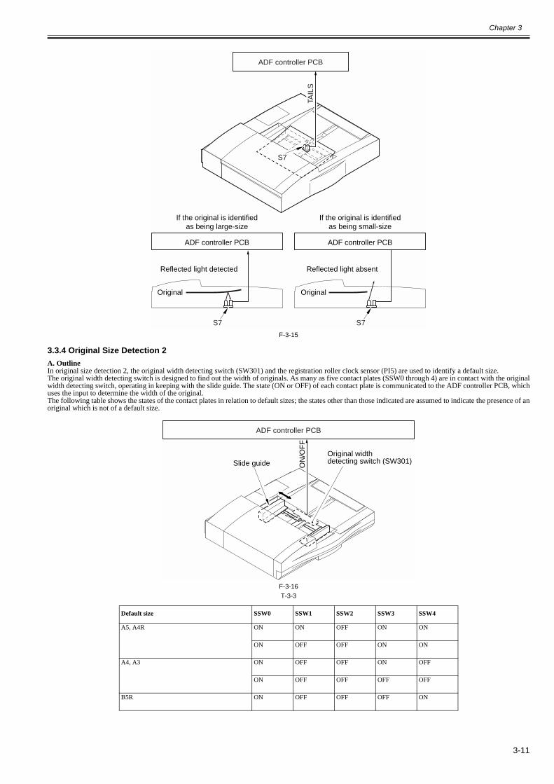
Chapter 3
3-11
F-3-15
3.3.4 Original Size Detection 20013-3471
A. OutlineIn original size detection 2, the original width detecting switch (SW301) and the registration roller clock sensor (PI5) are used to identify a default size.The original width detecting switch is designed to find out the width of originals. As many as five contact plates (SSW0 through 4) are in contact with the originalwidth detecting switch, operating in keeping with the slide guide. The state (ON or OFF) of each contact plate is communicated to the ADF controller PCB, whichuses the input to determine the width of the original.The following table shows the states of the contact plates in relation to default sizes; the states other than those indicated are assumed to indicate the presence of anoriginal which is not of a default size.
F-3-16T-3-3
Default size SSW0 SSW1 SSW2 SSW3 SSW4
A5, A4R ON ON OFF ON ON
ON OFF OFF ON ON
A4, A3 ON OFF OFF ON OFF
ON OFF OFF OFF OFF
B5R ON OFF OFF OFF ON
ADF controller PCB
ADF controller PCB
If the original is identifiedas being large-size
If the original is identifiedas being small-size
ADF controller PCB
Reflected light detected Reflected light absent
S7 S7
S7
Original Original
TAIL
S
Slide guide
ADF controller PCB
ON
/OF
F
Original widthdetecting switch (SW301)
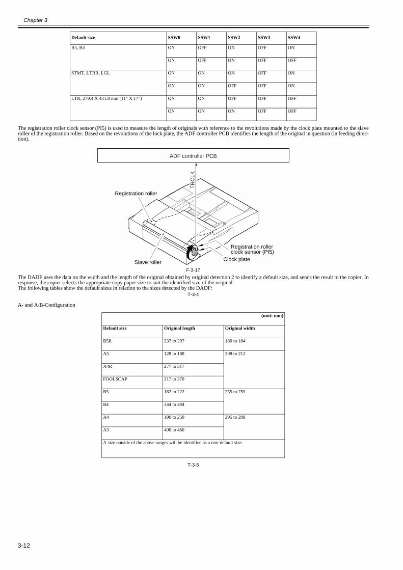
Chapter 3
3-12
The registration roller clock sensor (PI5) is used to measure the length of originals with reference to the revolutions made by the clock plate mounted to the slaveroller of the registration roller. Based on the revolutions of the lock plate, the ADF controller PCB identifies the length of the original in question (in feeding direc-tion).
F-3-17The DADF uses the data on the width and the length of the original obtained by original detection 2 to identify a default size, and sends the result to the copier. Inresponse, the copier selects the appropriate copy paper size to suit the identified size of the original.The following tables show the default sizes in relation to the sizes detected by the DADF:
T-3-4
A- and A/B-Configuration
T-3-5
B5, B4 ON OFF ON OFF ON
ON OFF ON OFF OFF
STMT, LTRR, LGL ON ON ON OFF ON
ON ON OFF OFF ON
LTR, 279.4 X 431.8 mm (11" X 17") ON ON OFF OFF OFF
ON ON ON OFF OFF
(unit: mm)
Default size Original length Original width
B5R 237 to 297 180 to 184
A5 128 to 188 208 to 212
A4R 277 to 317
FOOLSCAP 317 to 370
B5 162 to 222 255 to 259
B4 344 to 404
A4 190 to 250 295 to 299
A3 400 to 460
A size outside of the above ranges will be identified as a non-default size.
Default size SSW0 SSW1 SSW2 SSW3 SSW4
ADF controller PCB
Slave roller
Registration roller
Clock plate
Registration rollerclock sensor (PI5)
TR
CLK

Chapter 3
3-13
Inch-Configuration
T-3-6
Inch/A- and Inch/AB-Configuration
B. Slide Guide LockThe DADF is equipped with a slide guide lock so that the slide guide will not slide beyond the width of an A4/A3 sheet.To use an original wider than 297 mm, remove the slide guide lock (up to 305 mm; however, the feeding length must be 432 mm or less).
(unit: mm)
Default size Original length Original width
STMT 120 to 180 213 to 217.9
LTRR 259 to 309
FOOLSCAP 310 to 343
LGL 343 to 396
LTR 196 to 256 274.4 to 281.4
279.4X431.8 (11"X17") 412 to 472
A size outside of the above ranges will be identified as a non-default size.
(unit: mm)
Default size Original length Original width
B5R 237 to 297 180 to 184
A5 128 to 188 208 to 212
A4R 277 to 337
STMT 120 to 180 213.9 to 217.9
LTRR 259 to 309
FOOLSCAP 310 to 343
LGL 343 to 396
B5 162 to 222 255 to 259
B4 344 to 404
LTR 196 to 256 277.4 to 281.4
279.4X431.8 (11"X17") 412 to 472
A4 190 to 250 295 to 299
A3 400 to 460
A size outside of the above ranges will be identified as a non-default size.
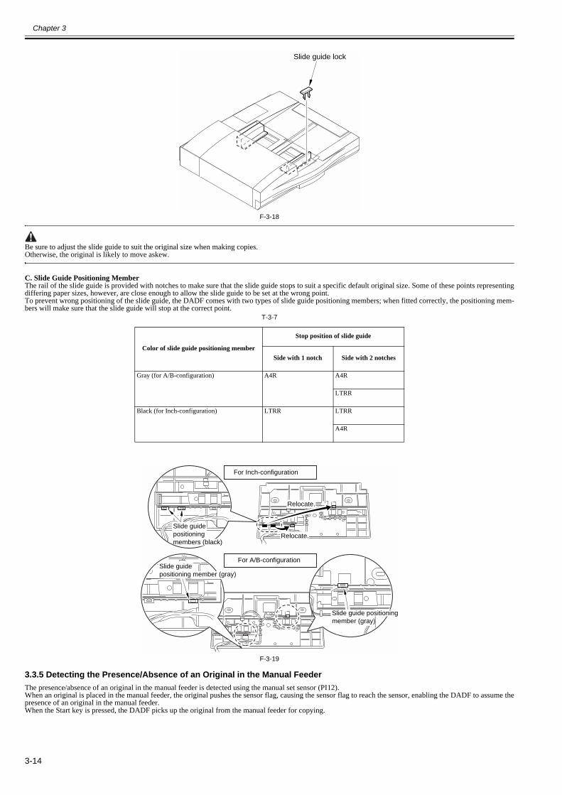
Chapter 3
3-14
F-3-18
Be sure to adjust the slide guide to suit the original size when making copies.Otherwise, the original is likely to move askew.
C. Slide Guide Positioning MemberThe rail of the slide guide is provided with notches to make sure that the slide guide stops to suit a specific default original size. Some of these points representingdiffering paper sizes, however, are close enough to allow the slide guide to be set at the wrong point.To prevent wrong positioning of the slide guide, the DADF comes with two types of slide guide positioning members; when fitted correctly, the positioning mem-bers will make sure that the slide guide will stop at the correct point.
T-3-7
F-3-19
3.3.5 Detecting the Presence/Absence of an Original in the Manual Feeder0013-3476
The presence/absence of an original in the manual feeder is detected using the manual set sensor (PI12).When an original is placed in the manual feeder, the original pushes the sensor flag, causing the sensor flag to reach the sensor, enabling the DADF to assume thepresence of an original in the manual feeder.When the Start key is pressed, the DADF picks up the original from the manual feeder for copying.
Color of slide guide positioning member
Stop position of slide guide
Side with 1 notch Side with 2 notches
Gray (for A/B-configuration) A4R A4R
LTRR
Black (for Inch-configuration) LTRR LTRR
A4R
Slide guide lock
Slide guidepositioning member (gray)
Slide guidepositioning members (black)
Relocate.
Relocate.
For Inch-configuration
For A/B-configuration
Slide guide positioningmember (gray)
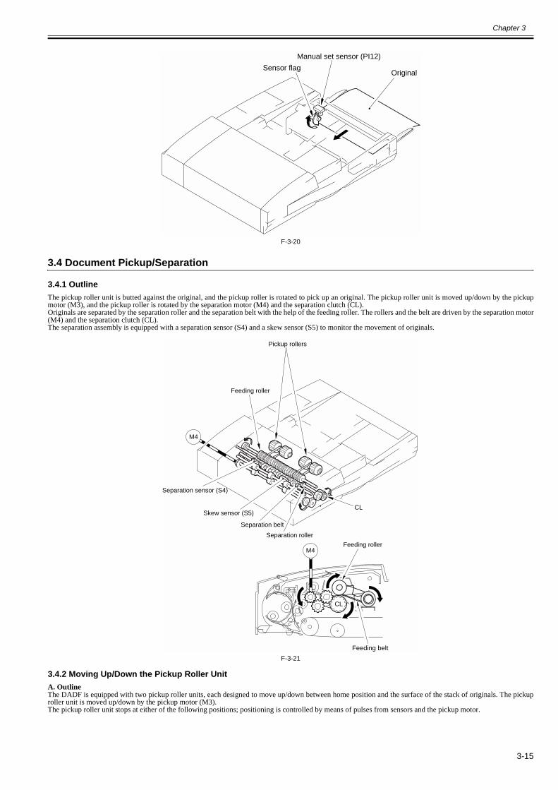
Chapter 3
3-15
F-3-20
3.4 Document Pickup/Separation
3.4.1 Outline0013-3478
The pickup roller unit is butted against the original, and the pickup roller is rotated to pick up an original. The pickup roller unit is moved up/down by the pickupmotor (M3), and the pickup roller is rotated by the separation motor (M4) and the separation clutch (CL).Originals are separated by the separation roller and the separation belt with the help of the feeding roller. The rollers and the belt are driven by the separation motor(M4) and the separation clutch (CL).The separation assembly is equipped with a separation sensor (S4) and a skew sensor (S5) to monitor the movement of originals.
F-3-21
3.4.2 Moving Up/Down the Pickup Roller Unit0013-3479
A. OutlineThe DADF is equipped with two pickup roller units, each designed to move up/down between home position and the surface of the stack of originals. The pickuproller unit is moved up/down by the pickup motor (M3).The pickup roller unit stops at either of the following positions; positioning is controlled by means of pulses from sensors and the pickup motor.
Manual set sensor (PI12)
Sensor flagOriginal
Feeding roller
Feeding belt
CL
Feeding roller
Separation roller
Separation belt
M4
M4
CL
Separation sensor (S4)
Skew sensor (S5)
Pickup rollers
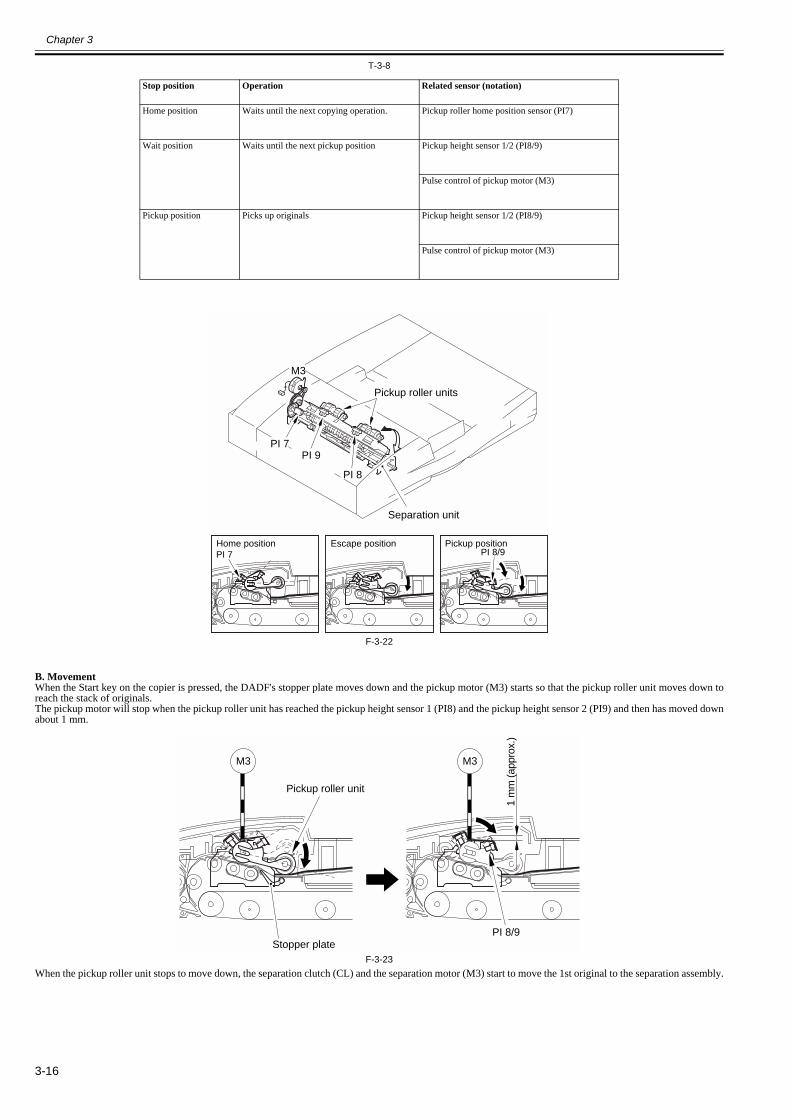
Chapter 3
3-16
T-3-8
F-3-22
B. MovementWhen the Start key on the copier is pressed, the DADF's stopper plate moves down and the pickup motor (M3) starts so that the pickup roller unit moves down toreach the stack of originals.The pickup motor will stop when the pickup roller unit has reached the pickup height sensor 1 (PI8) and the pickup height sensor 2 (PI9) and then has moved downabout 1 mm.
F-3-23When the pickup roller unit stops to move down, the separation clutch (CL) and the separation motor (M3) start to move the 1st original to the separation assembly.
Stop position Operation Related sensor (notation)
Home position Waits until the next copying operation. Pickup roller home position sensor (PI7)
Wait position Waits until the next pickup position Pickup height sensor 1/2 (PI8/9)
Pulse control of pickup motor (M3)
Pickup position Picks up originals Pickup height sensor 1/2 (PI8/9)
Pulse control of pickup motor (M3)
Home position Escape position Pickup position
M3
PI 9
PI 8
PI 8/9
PI 7
PI 7
Pickup roller units
Separation unit
M3 M3
1 m
m (a
ppro
x.)
PI 8/9
Pickup roller unit
Stopper plate

Chapter 3
3-17
F-3-24When the leading edge of the 1st original reaches the separation sensor (S4), the pickup motor (M3) starts to rotate to move the pickup roller unit from the surfaceof the stack of originals. The pickup roller unit stops about 6 mm from the surface of the stack of originals.
F-3-25When the trailing edge of the 1st original moves past the point of contact [1] of the pickup roller, the pickup roller unit once again moves down to the surface ofthe stack of originals to pick up the 2nd original.
F-3-26
3.4.3 Switching the Separation Pressure0013-3480
The DADF's separation assembly is equipped with a separation pressure switching mechanism which enables switching between two settings (low or high).The separation pressure may be switched by operating the separation pressure lever located in front of the separation assembly. When the lever is operated, theposition of the separation belt moves up or down to change the amount of overlap in relation to the feeding roller, thereby varying the separation pressure.
MEMO:The separation pressure lever is set to "Low" at time of shipment from the factory.
M4
CL
M3
Separation sensor (S4)
6 m
m (
appr
ox.)
M3
[1]

Chapter 3
3-18
F-3-27
3.4.4 Separation Sensor (S4) and Skew Sensor (S5)0013-3481
The paper path is equipped with a separation sensor (S4) and a skew sensor (S5) to monitor the movement of originals for the following:T-3-9
A separation fault (delay) is identified if the separation sensor does not detect an original a specific period of time after the separation motor has started to rotate.
F-3-28Both separation sensor and skew sensor are used to find out whether an original is moving askew. These two sensors are arranged in a single row in front-reardirection. An original is identified as moving askew if a discrepancy in timing is detected when it moves past these sensors. If the discrepancy is an equivalent of10 mm, the DADF will assume that the original is moving askew, at which point it stops its operation to protect the original and causes the copier to indicate a jammessage.
Item Sensor used (notation) Alarm
Separation fault (delay) Separation sensor (S4) 0031
Skew Separation sensor (S4) 0011
Skew sensor (S5)
High Low
Separation sensor (S4)
Separation sensor does not detect an original fora specific period of time
Separation sensor goes on withina specific period of time
Separation sensor (S4)
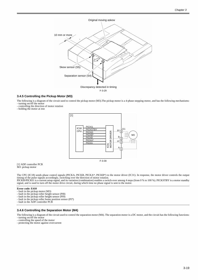
Chapter 3
3-19
F-3-29
3.4.5 Controlling the Pickup Motor (M3)0013-3482
The following is a diagram of the circuit used to control the pickup motor (M3).The pickup motor is a 4-phase stepping motor, and has the following mechanisms:- turning on/off the motor- controlling the direction of motor rotation- holding the motor at rest
F-3-30[1] ADF controller PCBM3: pickup motor
The CPU (IC18) sends phase control signals (PICKA, PICKB, PICKA*, PICKB*) to the motor driver (IC31). In response, the motor driver controls the outputtiming of the pulse signals accordingly, switching over the direction of motor rotation.PICKI0/PICKI1 is a current setup signal, and its variation (combination) enables a switch-over among 4 steps (from 0 % to 100 %). PICKSTBY is a motor standbysignal, and is used to turn off the motor drive circuit, during which time no phase signal is sent to the motor.
Error code: E410- fault in the pickup motor (M3)- fault in the pickup roller height sensor (PI8)- fault in the pickup roller height sensor (PI9)- fault in the pickup roller home position sensor (PI7)- fault in the ADF controller PCB
3.4.6 Controlling the Separation Motor (M4)0013-3483
The following is a diagram of the circuit used to control the separation motor (M4). The separation motor is a DC motor, and the circuit has the following functions:- turning on/off the motor- controlling the speed of the motor- protecting the motor against overcurrent
Original moving askew
Skew sensor (S5)
Separation sensor (S4)
Discrepancy detected in timing
10 mm or more
M3
IC31
MO
TOR
DR
IVE
R
IC18CPU
J114B*
B
PICKI1
A*
A
2
[1]
1
3
PICKSTBYPICKI0PICKB*PICKBPICKA*PICKA
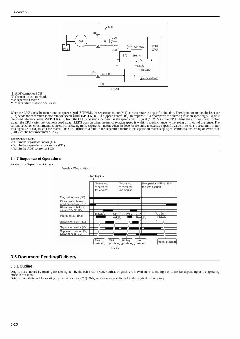
Chapter 3
3-20
F-3-31[1] ADF controller PCB[2] Current detection circuitM4: separation motorMI2: separation motor clock sensor
When the CPU sends the motor rotation speed signal (SPPWM), the separation motor (M4) starts to rotate in a specific direction. The separation motor clock sensor(PI2) sends the separation motor rotation speed signal (SPCLK) to IC17 (speed control IC). In response, IC17 compares the arriving rotation speed signal againstthe speed reference signal (SEPCLKREF) from the CPU, and sends the result as the speed control signal (SPMFV) to the CPU. Using the arriving speed controlsignal, the CPU varies the rotation speed signal. LED3 goes on when the motor rotation speed is within a specific range, while going off if out of the range. Thecurrent detection circuit monitors the current flowing in the separation motor; when the level of the current exceeds a specific value, it sends the separation motorstop signal (SPLIM) to stop the motor. The CPU identifies a fault in the separation motor if the separation motor stop signal continues, indicating an error code(E405) on the host machine's display.
Error code: E405- fault in the separation motor (M4)- fault in the separation clock sensor (PI2)- fault in the ADF controller PCB
3.4.7 Sequence of Operations0013-3484
Picking Up/ Separation Originals
F-3-32
3.5 Document Feeding/Delivery
3.5.1 Outline0013-3485
Originals are moved by rotating the feeding belt by the belt motor (M2). Further, originals are moved either to the right or to the left depending on the operatingmode in question.Originals are delivered by rotating the delivery motor (M5). Originals are always delivered to the original delivery tray.
M4
SPLIM
SPPWM
SPCLKSEPCLKREF
SPMFV
+24R
+5V
J12
J8
PI 2IC18CPUQ28
Q29
LED3
IC16
1
2
5
Start key ON
Original sensor (S6)
Pickup roller homeposition sensor (PI 7)Pickup roller heightsensor 1/2 (PI 8/9)
Pickup motor (M3)
Separation motor (M4)
Separation clutch (CL)
Separation sensor (S4)Skew sensor (S5)
UP DOWN UP UPDOWN
Picking up/separating1st original
Picking up/separating2nd original
EndPickup roller shiftingto home position
Feeding/Separation
Pickupposition
Waitposition
Pickupposition
Waitposition Home position
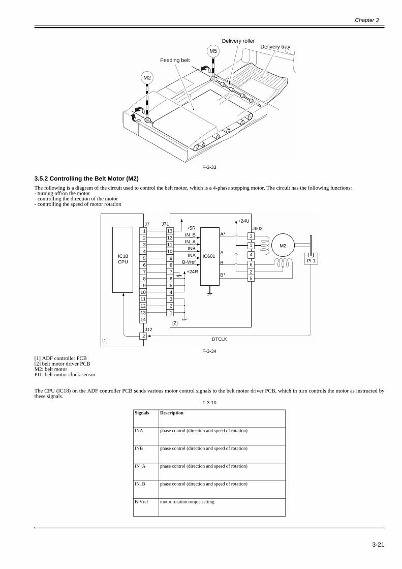
Chapter 3
3-21
F-3-33
3.5.2 Controlling the Belt Motor (M2)0013-3486
The following is a diagram of the circuit used to control the belt motor, which is a 4-phase stepping motor. The circuit has the following functions:- turning off/on the motor- controlling the direction of the motor- controlling the speed of motor rotation
F-3-34[1] ADF controller PCB[2] belt motor driver PCBM2: belt motorPI1: belt motor clock sensor
The CPU (IC18) on the ADF controller PCB sends various motor control signals to the belt motor driver PCB, which in turn controls the motor as instructed bythese signals.
T-3-10
Signals Description
INA phase control (direction and speed of rotation)
INB phase control (direction and speed of rotation)
IN_A phase control (direction and speed of rotation)
IN_B phase control (direction and speed of rotation)
B-Vref motor rotation torque setting
M5
M2
Delivery trayDelivery roller
Feeding belt
IC18CPU
IC601
+24U
+24R
A*
A
B
B*
M2
+5RIN_BIN_A
INBINA
B-Vref
J602J71J7
PI 1
J12
BTCLK
13121110
987654321
123456789
1011121314
2
3
1
4
6
25
[1]
[2]

Chapter 3
3-22
Error code: E402- fault in the belt motor (M2)- fault in the belt motor clock sensor (PI1)- fault in the ADF controller PCB
3.5.3 Controlling the Delivery Motor (M5)0013-3487
The following is a diagram of the circuit used to control the delivery motor (M5), which is a DC motor. The circuit has the following functions:- turning on/off the motor- controlling the speed of motor rotation
F-3-35[1] ADF controller PCBM5: delivery motorPI11: delivery motor clock sensor
The CPU (IC18) on the ADF controller PCB sends the motor rotation speed signal (EJMPWM*) to the drive control block, which in turn generates the motor drivesignal (EJMD*) in keeping with the arriving signal.The rotation of the motor generates the motor rotation signal (EJCLK), used by the CPU to monitor the operation of the motor.
T-3-11
Error code: E404- fault in the delivery motor (M5)- fault in the delivery motor clock sensor (PI11)- fault in the ADF controller PCB
- Related adjustment - sensor/delivery motor adjustment: when replacing the delivery motor
3.6 Feeding Unit
3.6.1 Outline of CW Pickup/Delivery0013-3489
The machine uses CW pickup/delivery both in fixed reading mode and in stream reading mode.
Signal Description
EJMPWM * motor rotation speed control
EJMD * motor operation drive control
EJCLK motor operation monitoring
+3.3v
+24R
M5Q19
Q20IC7
J2
J3
IC18CPU
EJMD*EJMPWM*
PI 11
EJCLKEJCLK
11
12
2
[1]
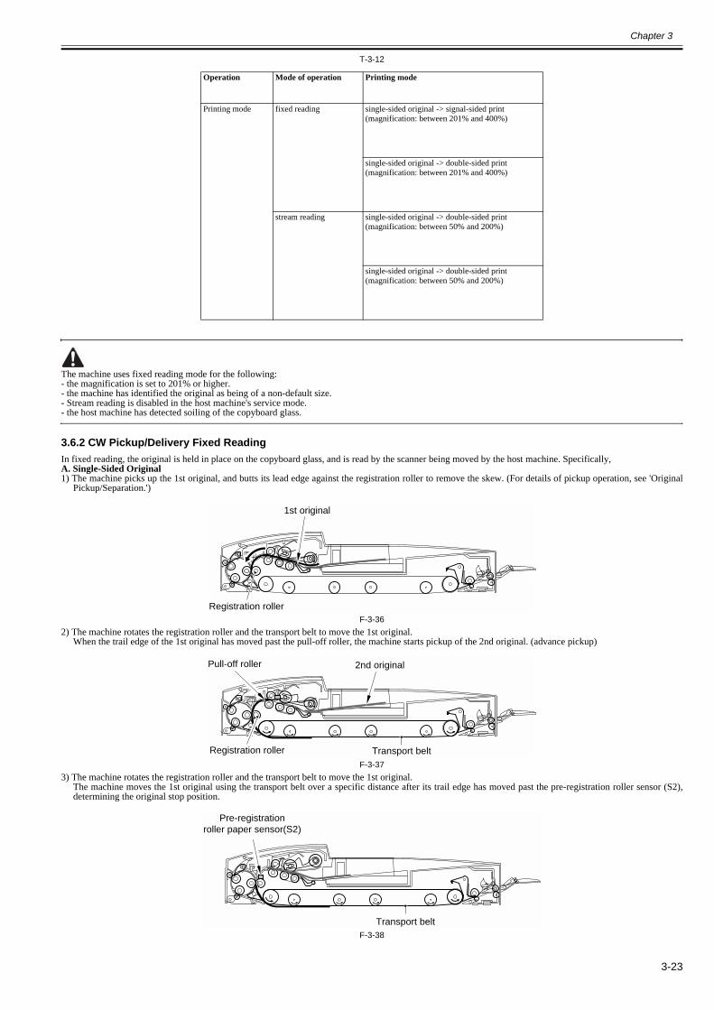
Chapter 3
3-23
T-3-12
The machine uses fixed reading mode for the following:- the magnification is set to 201% or higher.- the machine has identified the original as being of a non-default size.- Stream reading is disabled in the host machine's service mode.- the host machine has detected soiling of the copyboard glass.
3.6.2 CW Pickup/Delivery Fixed Reading0013-3491
In fixed reading, the original is held in place on the copyboard glass, and is read by the scanner being moved by the host machine. Specifically,A. Single-Sided Original1) The machine picks up the 1st original, and butts its lead edge against the registration roller to remove the skew. (For details of pickup operation, see 'Original
Pickup/Separation.')
F-3-362) The machine rotates the registration roller and the transport belt to move the 1st original.
When the trail edge of the 1st original has moved past the pull-off roller, the machine starts pickup of the 2nd original. (advance pickup)
F-3-373) The machine rotates the registration roller and the transport belt to move the 1st original.
The machine moves the 1st original using the transport belt over a specific distance after its trail edge has moved past the pre-registration roller sensor (S2),determining the original stop position.
F-3-38
Operation Mode of operation Printing mode
Printing mode fixed reading single-sided original -> signal-sided print (magnification: between 201% and 400%)
single-sided original -> double-sided print (magnification: between 201% and 400%)
stream reading single-sided original -> double-sided print (magnification: between 50% and 200%)
single-sided original -> double-sided print (magnification: between 50% and 200%)
Registration roller
1st original
Registration roller Transport belt
2nd originalPull-off roller
Pre-registrationroller paper sensor(S2)
Transport belt

Chapter 3
3-24
4) The host machine starts printing operation using its scanner.
F-3-395) When the host machine's scanner starts to move in reverse, the machine rotates the transport belt in reverse to move the 1st original in the direction of delivery.
At the same time, the machine rotates the registration roller to move the 2nd original.
F-3-406) The machine moves the 1st and 2nd originals using the transport belt; rotating it over a specific distance after the trail edge of the 2nd original has moved past
the pre-registration roller paper sensor (S2) to determine the stop position for the 2nd original.The machine moves the 1st original in the direction of delivery, stopping it on the copyboard glass.
F-3-41In the case of a large-size original, the machine controls the distance between sheets so that only a single original is on the copyboard glass at a time in step 6.
B. Sequence of Operation (single-sided original)
F-3-42
C. Mix of Single-Sided Originals1) The 1st original is picked up, and its lead edge is butted against the registration roller to remove the skew. (For details of pickup operation, see 'Original Pickup/
Separation.')
2nd original
Pre-registration roller paper sensor(S2)
2nd original 1st original
COPYStart key ON
Original sensor (S6)
Pickup roller homeposition sensor (PI 7)
Pickup roller heightsensor 1/2 (PI 8/9)
Stopper plate solenoid (SL2)
Pickup motor (M3)
Separation motor (M4)
Separation clutch (CL)
Reversal motor (M1)
Belt motor (M2)
Delivery motor (M5)
UP DOWN UP DOWN UP UPDOWN
separates 1st original
moves 1st original in delivery directionreads 2nd originalseparates 3rd original
delivers 1st originalmoves 2nd original in delivery directionreads 3rd direction
delivers 2nd originalmoves 3rd original in delivery direction
delivers 3rd original
reads 1st originalseparates 2nd original
A4 Single-Sided Originals; Fixed Reading
: motor reverse rotation
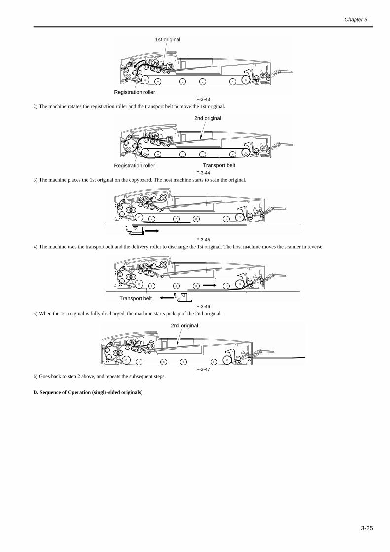
Chapter 3
3-25
F-3-432) The machine rotates the registration roller and the transport belt to move the 1st original.
F-3-443) The machine places the 1st original on the copyboard. The host machine starts to scan the original.
F-3-454) The machine uses the transport belt and the delivery roller to discharge the 1st original. The host machine moves the scanner in reverse.
F-3-465) When the 1st original is fully discharged, the machine starts pickup of the 2nd original.
F-3-476) Goes back to step 2 above, and repeats the subsequent steps.
D. Sequence of Operation (single-sided originals)
Registration roller
1st original
Registration roller Transport belt
2nd original
Transport belt
2nd original
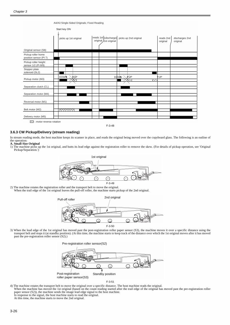
Chapter 3
3-26
F-3-48
3.6.3 CW Pickup/Delivery (stream reading) 0013-3509
In stream reading mode, the host machine keeps its scanner in place, and reads the original being moved over the copyboard glass. The following is an outline ofthe operation:A. Small-Size Original1) The machine picks up the 1st original, and butts its lead edge against the registration roller to remove the skew. (For details of pickup operation, see 'Original
Pickup/Separation.')
F-3-492) The machine rotates the registration roller and the transport belt to move the original.
When the trail edge of the 1st original leaves the pull-off roller, the machine starts pickup of the 2nd original.
F-3-503) When the lead edge of the 1st original has moved past the post-registration roller paper sensor (S3), the machine moves it over a specific distance using the
transport belt and stops it (at standby position). (At this time, the machine starts to keep track of the distance over which the 1st original moves after it has movedpast the pre-registration roller sensor (S2).)
F-3-514) The machine rotates the transport belt to move the original over a specific distance. The host machine reads the original.
When the machine has moved the 1st original (based on the count reading started after the trail edge of the original has moved past the pre-registration rollerpaper sensor (S2)), the machine sends the image lead edge signal to the host machine.In response to the signal, the host machine starts to read the original.At this time, the machine starts to move the 2nd original.
Start key ON
Original sensor (S6)
Pickup roller home position sensor (PI 7)
Pickup roller heightsensor 1/2 (PI 8/9)
Stopper plate solenoid (SL2)
Pickup motor (M3)
Separation motor (M4)
Separation clutch (CL)
Reversal motor (M1)
Belt motor (M2)
Delivery motor (M5)
UP DOWN UP UPDOWN
picks up 1st original reads 1st original
1discharges 1st original
picks up 2nd original reads 2nd original
discharges 2nd original
A4/A3 Single-Sided Originals; Fixed Reading
: motor reverse rotation
1st original
2nd originalPull-off roller
Standby positionPost-registration roller paper sensor(S3)
Pre-registration roller sensor(S2)

Chapter 3
3-27
F-3-525) The machine rotates the transport belt to move the 2nd original. If the read signal arrives from the host machine before the 2nd original reaches the front position
(25 mm + stop distance), the machine does not stop the original for reading. If the signal does not arrive before the original reaches the front position (25 mm +stop distance), on the other hand, the machine stops the original in standby position and then rotates the transport belt for reading of the 2nd original.
F-3-536) The machine goes back to step 2. above and repeats the subsequent steps.
B. Sequence of Operation (small-size original)
F-3-54
C. Large-Size Original1) The 1st original is picked up, and its lead edge is butted against the registration roller to remove the skew. (For details of pickup operation, see 'Original Pickup/
Separation.')
F-3-552) The machine rotates the registration roller and the transport belt to move the original.
When the trail edge of the 1st original moves past the pre-registration roller sensor (S2), the machine starts pickup of the 2nd original.(if the original is 279.4 x 431.8 mm (11x17), after the original starts to move in 4)
2nd original
Pre-registration roller paper sensor(S2)
2nd original
UP DOWN UP DOWN UP UPDOWN
separates 1st original
holds 1st original in standby
separates 2nd original
reads 1st original holds 2nd original in standbyseparates 3rd original
discharges 1st originalreads 2nd originalholds 3rd original in standby
discharges 2nd originalreads 3rd original
discharges 3rd original
A4 Single-Sided Originals; Stream Reading
does not stop 2nd original before reading
stops 3rd original before reading
Original sensor (S6)
Pickup roller home position sensor (PI 7)
Pickup roller heightsensor 1/2 (PI 8/9)
Stopper plate solenoid (SL2)
Pickup motor (M3)
Separation motor (M4)
Separation clutch (CL)
Reversal motor (M1)
Belt motor (M2)
Delivery motor (M5)
: motor reversal rotation
Start key ON
1st original
Registration roller
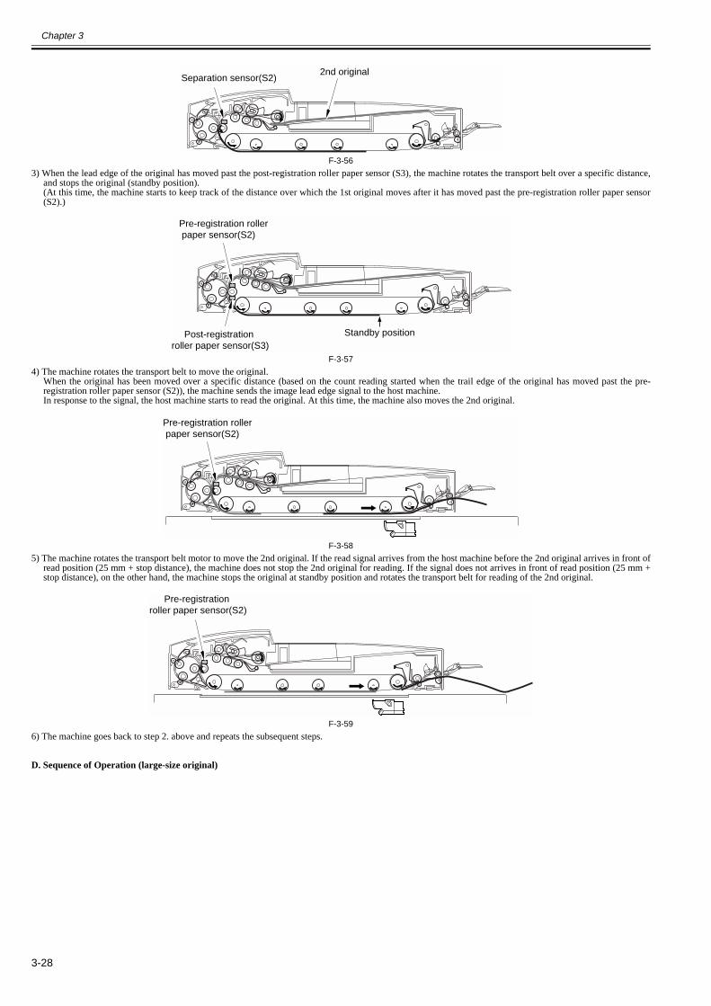
Chapter 3
3-28
F-3-563) When the lead edge of the original has moved past the post-registration roller paper sensor (S3), the machine rotates the transport belt over a specific distance,
and stops the original (standby position).(At this time, the machine starts to keep track of the distance over which the 1st original moves after it has moved past the pre-registration roller paper sensor(S2).)
F-3-574) The machine rotates the transport belt to move the original.
When the original has been moved over a specific distance (based on the count reading started when the trail edge of the original has moved past the pre-registration roller paper sensor (S2)), the machine sends the image lead edge signal to the host machine.In response to the signal, the host machine starts to read the original. At this time, the machine also moves the 2nd original.
F-3-585) The machine rotates the transport belt motor to move the 2nd original. If the read signal arrives from the host machine before the 2nd original arrives in front of
read position (25 mm + stop distance), the machine does not stop the 2nd original for reading. If the signal does not arrives in front of read position (25 mm +stop distance), on the other hand, the machine stops the original at standby position and rotates the transport belt for reading of the 2nd original.
F-3-596) The machine goes back to step 2. above and repeats the subsequent steps.
D. Sequence of Operation (large-size original)
2nd originalSeparation sensor(S2)
Standby positionPost-registration roller paper sensor(S3)
Pre-registration roller paper sensor(S2)
Pre-registration roller paper sensor(S2)
Pre-registration roller paper sensor(S2)
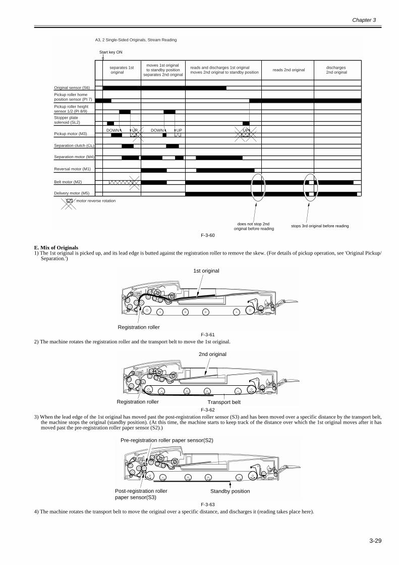
Chapter 3
3-29
F-3-60
E. Mix of Originals1) The 1st original is picked up, and its lead edge is butted against the registration roller to remove the skew. (For details of pickup operation, see 'Original Pickup/
Separation.')
F-3-612) The machine rotates the registration roller and the transport belt to move the 1st original.
F-3-623) When the lead edge of the 1st original has moved past the post-registration roller sensor (S3) and has been moved over a specific distance by the transport belt,
the machine stops the original (standby position). (At this time, the machine starts to keep track of the distance over which the 1st original moves after it hasmoved past the pre-registration roller paper sensor (S2).)
F-3-634) The machine rotates the transport belt to move the original over a specific distance, and discharges it (reading takes place here).
Start key ON
Original sensor (S6)
Pickup roller home position sensor (PI 7)
Pickup roller heightsensor 1/2 (PI 8/9)
Stopper plate solenoid (SL2)
Pickup motor (M3)
Separation motor (M4)
Separation clutch (CL)
Reversal motor (M1)
Belt motor (M2)
Delivery motor (M5)
UP DOWN UP UPDOWN
separates 1st original
reads and discharges 1st originalmoves 2nd original to standby position
reads 2nd original discharges 2nd original
moves 1st original to standby position
separates 2nd original
A3, 2 Single-Sided Originals, Stream Reading
: motor reverse rotation
does not stop 2nd original before reading
stops 3rd original before reading
1st original
Registration roller
Registration roller Transport belt
2nd original
Standby positionPost-registration roller paper sensor(S3)
Pre-registration roller paper sensor(S2)
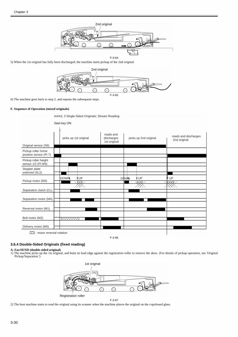
Chapter 3
3-30
F-3-645) When the 1st original has fully been discharged, the machine starts pickup of the 2nd original.
F-3-656) The machine goes back to step 2. and repeats the subsequent steps.
F. Sequence of Operation (mixed originals)
F-3-66
3.6.4 Double-Sided Originals (fixed reading) 0013-3510
A. Fax/SEND (double-sided original)1) The machine picks up the 1st original, and butts its lead edge against the registration roller to remove the skew. (For details of pickup operation, see 'Original
Pickup/Separation.')
F-3-672) The host machine starts to read the original using its scanner when the machine places the original on the copyboard glass.
2nd original
2nd original
Start key ON
Original sensor (S6)
Pickup roller home position sensor (PI 7)
Pickup roller heightsensor 1/2 (PI 8/9)
Stopper plate solenoid (SL2)
Pickup motor (M3)
Separation motor (M4)
Separation clutch (CL)
Reversal motor (M1)
Belt motor (M2)
Delivery motor (M5)
UP DOWN UP UPDOWN
picks up 1st originalreads and discharges 1st original
picks up 2nd originalreads and discharges 2nd original
A4/A3, 3 Single-Sided Originals; Stream Reading
: motor reversal rotation
Registration roller
1st original
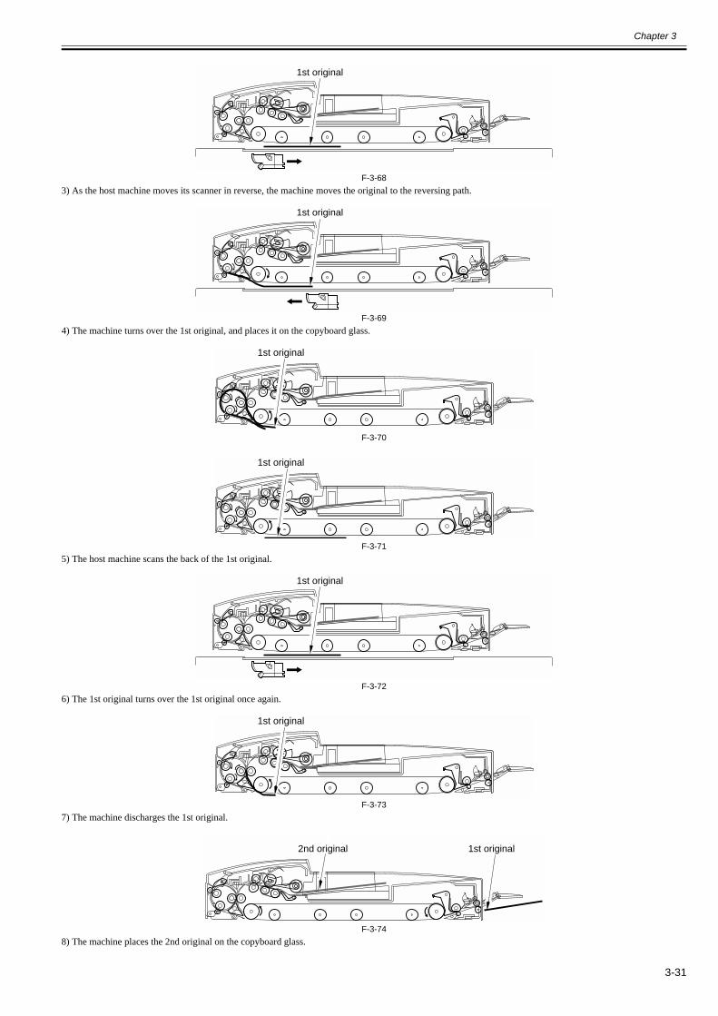
Chapter 3
3-31
F-3-683) As the host machine moves its scanner in reverse, the machine moves the original to the reversing path.
F-3-694) The machine turns over the 1st original, and places it on the copyboard glass.
F-3-70
F-3-715) The host machine scans the back of the 1st original.
F-3-726) The 1st original turns over the 1st original once again.
F-3-737) The machine discharges the 1st original.
F-3-748) The machine places the 2nd original on the copyboard glass.
1st original
1st original
1st original
1st original
1st original
1st original
1st original2nd original
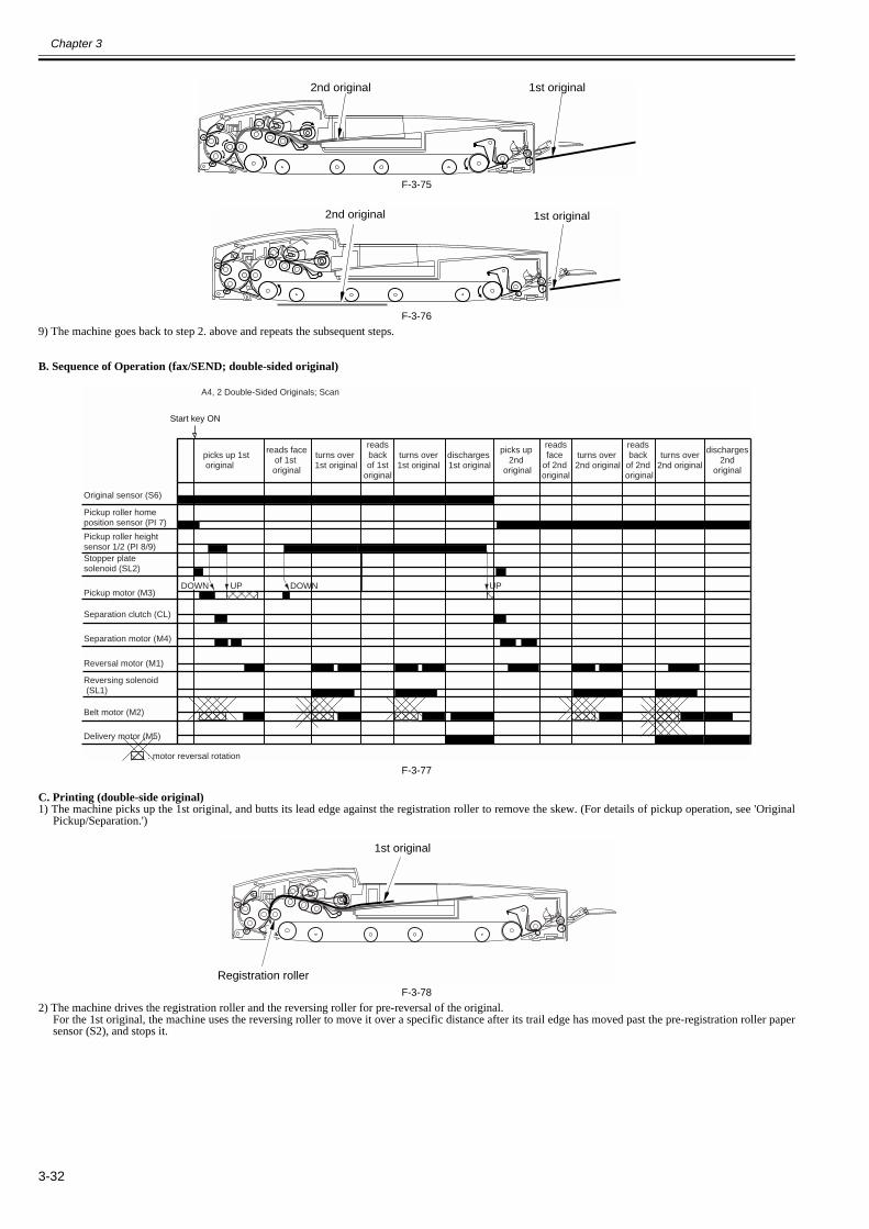
Chapter 3
3-32
F-3-75
F-3-769) The machine goes back to step 2. above and repeats the subsequent steps.
B. Sequence of Operation (fax/SEND; double-sided original)
F-3-77
C. Printing (double-side original)1) The machine picks up the 1st original, and butts its lead edge against the registration roller to remove the skew. (For details of pickup operation, see 'Original
Pickup/Separation.')
F-3-782) The machine drives the registration roller and the reversing roller for pre-reversal of the original.
For the 1st original, the machine uses the reversing roller to move it over a specific distance after its trail edge has moved past the pre-registration roller papersensor (S2), and stops it.
1st original2nd original
1st original2nd original
Reversing solenoid (SL1)
DOWN UPDOWN UP
A4, 2 Double-Sided Originals; Scan
picks up 1st original
turns over 1st original
turns over 2nd original
reads faceof 1st original
turns over1st original
discharges 1st original
picks up 2nd
original
readsbackof 1st
original
readsface
of 2nd original
reads back
of 2nd original
turns over2nd original
discharges2nd
original
Start key ON
Original sensor (S6)
Pickup roller home position sensor (PI 7)
Pickup roller heightsensor 1/2 (PI 8/9)Stopper plate solenoid (SL2)
Pickup motor (M3)
Separation motor (M4)
Separation clutch (CL)
Reversal motor (M1)
Belt motor (M2)
Delivery motor (M5)
: motor reversal rotation
1st original
Registration roller
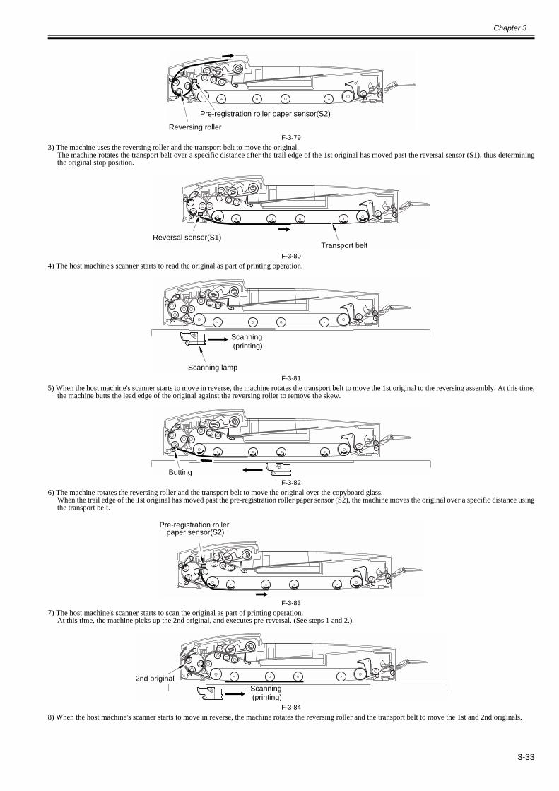
Chapter 3
3-33
F-3-793) The machine uses the reversing roller and the transport belt to move the original.
The machine rotates the transport belt over a specific distance after the trail edge of the 1st original has moved past the reversal sensor (S1), thus determiningthe original stop position.
F-3-804) The host machine's scanner starts to read the original as part of printing operation.
F-3-815) When the host machine's scanner starts to move in reverse, the machine rotates the transport belt to move the 1st original to the reversing assembly. At this time,
the machine butts the lead edge of the original against the reversing roller to remove the skew.
F-3-826) The machine rotates the reversing roller and the transport belt to move the original over the copyboard glass.
When the trail edge of the 1st original has moved past the pre-registration roller paper sensor (S2), the machine moves the original over a specific distance usingthe transport belt.
F-3-837) The host machine's scanner starts to scan the original as part of printing operation.
At this time, the machine picks up the 2nd original, and executes pre-reversal. (See steps 1 and 2.)
F-3-848) When the host machine's scanner starts to move in reverse, the machine rotates the reversing roller and the transport belt to move the 1st and 2nd originals.
Pre-registration roller paper sensor(S2)
Reversing roller
Reversal sensor(S1)Transport belt
Scanning lamp
Scanning (printing)
Butting
Pre-registration roller paper sensor(S2)
Scanning (printing)
2nd original
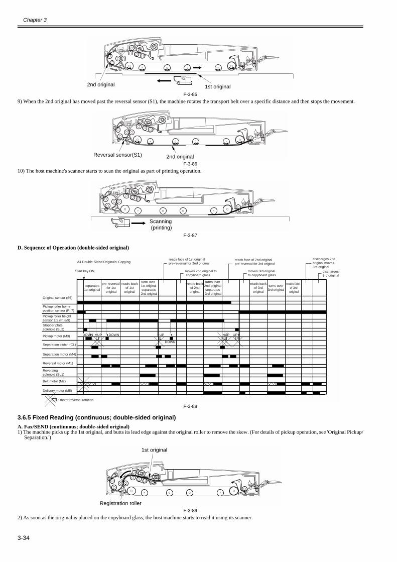
Chapter 3
3-34
F-3-859) When the 2nd original has moved past the reversal sensor (S1), the machine rotates the transport belt over a specific distance and then stops the movement.
F-3-8610) The host machine's scanner starts to scan the original as part of printing operation.
F-3-87
D. Sequence of Operation (double-sided original)
F-3-88
3.6.5 Fixed Reading (continuous; double-sided original)0013-3514
A. Fax/SEND (continuous; double-sided original)1) The machine picks up the 1st original, and butts its lead edge against the original roller to remove the skew. (For details of pickup operation, see 'Original Pickup/
Separation.')
F-3-892) As soon as the original is placed on the copyboard glass, the host machine starts to read it using its scanner.
1st original2nd original
Reversal sensor(S1) 2nd original
Scanning (printing)
Reversing solenoid (SL1)
DOWN
DOWN
UPUP UPDOWN UP
A4 Double-Sided Originals; Copying
separates1st original
pre-reversal for 1st original
moves 2nd original to copyboard glass
reads back of 1st original
reads back of 2nd original
turns over 1st originalseparates
2nd original
turns over2nd originalseparates
3rd original
reads face of 1st originalpre-reversal for 2nd original
reads face of 2nd originalpre-reversal for 3rd original
reads back of 3rd original
turns over3rd original
reads face of 3rd
original
moves 3rd originalto copyboard glass
discharges 2nd original moves 3rd original
Start key ON
Original sensor (S6)
Pickup roller home position sensor (PI 7)
Pickup roller heightsensor 1/2 (PI 8/9)
Stopper plate solenoid (SL2)
Pickup motor (M3)
Separation motor (M4)
Separation clutch (CL)
Reversal motor (M1)
Belt motor (M2)
Delivery motor (M5)
: motor reversal rotation
discharges 3rd original
Registration roller
1st original

Chapter 3
3-35
F-3-903) The machine sends the original to the reversing path as the host machine moves its scanner in reverse.
F-3-914) The machine turns over the 1st original, and places it on the copyboard glass.
F-3-92
F-3-935) The host machine scans the back of the 1st original
F-3-946) The machine turns over the 1st original once again.
F-3-957) The machine starts to pick up the 2nd original when the trail edge of the 1st original moves past the registration roller.
F-3-968) The machine places the 2nd original on the copyboard glass and, at the same time, discharges the 1st original.
1st original
1st original
1st original
1st original
1st original
1st original
1st original 2nd original

Chapter 3
3-36
F-3-97
F-3-989) The machine goes back to step 2. above and repeats the subsequent steps.
B. Sequence of Operation (fax/SEND; double-sided original)
F-3-99
C. Printing (double-sided original)1) The machine picks up the 1st original, and butts its lead edge against the registration roller to remove the skew. (For details of pickup operation, see 'Original
Pickup/Separation.')
F-3-1002) The machine places the original on the copyboard glass.
F-3-101
1st original2nd original
1st original2nd original
Reversal solenoid (SL1)
DOWN UPDOWN UP
A4, 2 Double-Sided Originals; Scan
picks up 1st original
turns over 1st original
turns over2nd original
reads face of
1st original
turns over 1st original
again
discharges1st original
picks up 2nd
original
readsback of
1storiginal
reads face of 2nd
original
readsback of
2nd original
reads back of 2nd original
turns over 2nd original again
Start key ON
Original sensor (S6)
Pickup roller home position sensor (PI 7)
Pickup roller heightsensor 1/2 (PI 8/9)
Stopper plate solenoid (SL2)
Pickup motor (M3)
Separation motor (M4)
Separation clutch (CL)
Reversal motor (M1)
Belt motor (M2)
Delivery motor (M5)
: motor reversal rotation
Registration roller
1st original
1st original

Chapter 3
3-37
3) The machine sends the original to the reversing path.
F-3-1024) The machine turns over the 1st original, and places it on the copyboard glass.
F-3-103
F-3-1045) The host machine scans the back of the 1st original.
F-3-1056) The machine sends the original to the reversing path as the host machine moves its scanner in reverse.
F-3-1067) The machine turns over the 1st original, and places it on the copyboard glass.
F-3-107
F-3-1088) As soon as the original is placed on the copyboard cover, the host machine uses its scanner to scan and read its face.
1st original
1st original
1st original
1st original
1st original
1st original
1st original
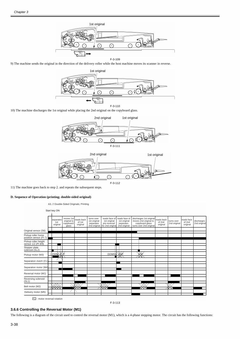
Chapter 3
3-38
F-3-1099) The machine sends the original in the direction of the delivery roller while the host machine moves its scanner in reverse.
F-3-11010) The machine discharges the 1st original while placing the 2nd original on the copyboard glass.
F-3-111
F-3-11211) The machine goes back to step 2. and repeats the subsequent steps.
D. Sequence of Operation (printing; double-sided original)
F-3-113
3.6.6 Controlling the Reversal Motor (M1)0013-3516
The following is a diagram of the circuit used to control the reversal motor (M1), which is a 4-phase stepping motor. The circuit has the following functions:
1st original
1st original
1st original2nd original
1st original2nd original
DOWN UP UPDOWN
moves 1storiginal to
copyboard glass
reads back of 2nd original
reads face of 1st originalseparates 2nd original
reads face of 2nd original
discharges 2nd original
discharges 1st originalmoves 2nd original to
copyboard glassturns over 2nd original
turns over2nd original
UP
A3, 2 Double-Sided Originals; Printing
Reversing solenoid (SL1)
Original sensor (S6)
Pickup roller home position sensor (PI 7)
Pickup roller heightsensor 1/2 (PI 8/9)
Stopper plate solenoid (SL2)
Pickup motor (M3)
Separation motor (M4)
Separation clutch (CL)
Reversal motor (M1)
Belt motor (M2)
Delivery motor (M5)
: motor reversal rotation
Start key ON
separates1st
original
reads back of 1st original
turns over 1st originalseparates
2nd original
reads face of1st original
pre-reversal for 2nd original

Chapter 3
3-39
- turning off/on the motor- controlling the direction of motor rotation- controlling the speed of motor rotation
F-3-114[1] ADF controller PCB[2] reversal motor drive PCBM1: reversal motorPI5: reversal motor clock sensor
The CPU (Q18) on the ADF controller PCB sends various motor control signals to the reversal motor driver PCB, which in turn controls the motor as dictated bythese signals.
T-3-13
3.6.7 Manual Feeder Pickup/Delivery Operation0013-3518
The machine uses 'manual feeder pickup/delivery' only for fixed reading mode.1) When an original is placed in the manual feeder, the manual feeder placement sensor (PI12) detects it.
F-3-1152) When the Start key is pressed, the machine uses the delivery roller to move the original until the lead edge of the original butts against the manual feeder regis-
tration roller (thus removing the skew).
F-3-1163) The machine moves the original to move the delivery roller and the transport belt. The original stops when its lead edge reaches the reversal sensor (S1).
Signal name Description
INA phase control (direction and speed of rotation)
INB phase control (direction and speed of rotation)
IN_A phase control (direction and speed of rotation)
IN_B phase control (direction and speed of rotation)
T-Vref motor rotation torque setting
IC18CPU
IC601
+24U
+24R
A*
A
B
B*
M1
+5RIN_BIN_A
INBINA
T-Vref
J602J71J6
PI 5
J14
TRCLK
13121110
987654321
123456789
10111213
B9
3
1
4
6
25
[1]
[2]
Manual feeder placement sensor(PI12)
Manual feeder registration sensor(S9)

Chapter 3
3-40
F-3-1174) The machine rotates the transport belt. The original is moved over a specific distance after its trail edge has moved past the reversal sensor (S1), and is then
stopped.
F-3-1185) The host machine starts printing operation.
F-3-1196) When the host machine's scanner starts to move in reverse, the machine starts to rotate the transport belt and the delivery roller, thus moving the original to the
delivery assembly.
F-3-120
Sequence of Operation
F-3-121
3.7 Detecting Jams
3.7.1 Overview 0013-3519
The machine checks for jams using the following sensors. The CPU on the ADF controller PCB runs a check at such times as programmed in advance, and detectsthe presence/absence of a jam in relation to the presence/absence of paper over a specific sensor.Upon detection of a jam, the machine communicates the fact to the host machine, which in turn indicates the fact in service mode in the form of a code. A checkmay also be made with reference to the indicator (DSP1) of the machine's ADF control PCB.
Service Mode Screen of the Host Machine
Reversal sensor(S1)
Reversal sensor(S1)
Copy
Start key ONOriginal placed in manual feeder
Belt motor (M2)
Delivery solenoid (M5)
Reversal solenoid(SL4)
Manual feeder placement sensor(PI 12)
Reversal sensor(SL1)Original delivery sensor(PI 1)Original placed in manual feeder(PI 13)
pickup print dischargemove
original placed
0.4 sec (approx.)

Chapter 3
3-41
F-3-122The indicator (DSP1) of the machine's controller PCB flashes 4 times to indicate a specific jam type:[EX: if code is 0013]
F-3-123
F-3-124
3.7.2 List of Jam Code0013-3520
The following shows jam codes, jam types, and associated sensors with descriptions of detection conditions:T-3-14
Code Sensor type Sensor notation
Description
0001 separation delay S4 At time of separation, the separation sensor does not detect the original when it has been moved over a specific distance (221 mm) after the start of the separation motor.
0002 pickup delay S4, S2 At time of separation, the pre-registration sensor does not detect the original when it has been moved over a specific distance (93 mm) after the separation sensor has detected its lead edge.
0003 pickup stationary 1 S3 At time of pickup, the post-registration sensor does not detect the original when it has been moved over a specific distance (40 mm) after the start of the reversal motor.
0004 pickup stationary 2 S2 At time of pickup, the pre-registration roller sensor detects the original when it has been moved over a specific distance (330 mm if small; 660 mm if large) after the start of the reversal motor.
0005 reversal delay S1 At time of reversal, the reversal sensor does not detect the original when it has been moved a specific distance (104 mm) from the platen roller.
0006 reversal stationary S1 At time of reversal, the reversal sensor detects the original when it has been moved over a specific distance (original length x 1.5 mm) after the end of arching.
0007 delivery delay PI13 At time of delivery, the delivery sensor does not detect the original when it has been moved over a specific distance (631 mm - original length) after the start of the belt motor.
0008 delivery stationary 1 PI13, S9 At time of delivery, the manual feeder registration roller sensor detects the original when it has been moved over a specific distance (original length + 100 mm) after the delivery sensor has gone on.
0009 delivery stationary 2 PI13, S9 At time of delivery, the delivery sensor detects the original when it has been moved over a specific distance (100 mm) after the manual feeder registration roller sensor has gone off.
0010 pre-reversal delay 1 S3 At time of pre-reversal, the post-registration roller sensor does not detect the original after it has been moved over a specific distance (50 mm) from the start of the reversal motor.
0011 pre-reversal delay 2 S1, S3 At time of pre-reversal, the reversal sensor does not detect the original when it has been moved over a specific distance (100 mm) after the post-registration roller sensor has gone on.
Jam code[1] indicates the presence
of a jam in the machine
PI 4 PI 7
PI6PI3
PI12
PI 8,PI 9
S1
S2
S3
S7
S9
PI 10PI 13
S4,S5
S6 (light-emitting)
S6(light-receiving)

Chapter 3
3-42
0012 pre-reversal delay 2 PI4 At time of pre-reversal, the pre-reversal sensor does not detect an original when the reversal motor stops.
0013 pre-reversal stationary 1 S1, S4 At time of pre-reversal, the separation sensor detects the original when it has been moved over a specific distance (169 mm) after the reversal sensor has gone on.
0014 pre-reversal stationary 2 S2, S4 At time of pre-reversal, the pre-registration roller sensor detects the original when it has been moved over a specific distance (120 mm) after its trail edge has moved past the separation pull-off roller.
0015 pre-reversal stationary 3 S2, S3 At time of reversal, the post-registration sensor detects the original when it has been moved over a specific distance (50 mm) after its trail edge has moved past the pre-registration roller sensor.
0016 pre-reversal stationary 4 S1, S3 At time of pre-reversal, the reversal sensor detects the original when it has been moved over a specific distance (100 mm) after the start of the reversal motor.
0017 pre-reversal pickup delay S1 At time of pre-reversal pickup, the reversal sensor does not detect the original when it has been moved over a specific distance (100 mm) after the start of the reversal motor.
0018 pre-reversal pickup stationary 1 S1, PI4 At time of pre-reversal pickup, the pre-reversal sensor detects the original when it has been moved over a specific distance after the reversal sensor has detected its lead edge.
0019 pre-reversal pickup stationary 2 S1, PI4 At time of reversal pickup, the reversal sensor detects the original when it has been moved over a specific distance after the pre-reversal sensor has detected its trail edge.
0020 reversal pickup delay S2 At time of reversal, the pre-registration roller sensor does not detect the original when it has been moved over a specific distance (197 mm) after the end of arching.
0021 reversal pickup stationary S2 At time of reversal, the pre-registration sensor detects the original when it has been moved over a specific distance (original length x 1.5 mm) after the pre-registration roller sensor has gone on.
0022 pickup lead edge skew S4, S5 At time of separation, there is a discrepancy of 10 mm in timing of lead edge detection between separation sensor and skew sensor.
0023 pickup trail edge skew S4, S5 A time of pickup, there is a discrepancy of 10 mm in timing of trail edge detection between separation sensor and skew sensor.
0024 pickup NG1 S1 At time of pickup, the reversal sensor detects the original before it has moved past the pre-registration roller sensor.
0025 pickup NG2 S2, S3 At time of pickup, the post-registration roller sensor detects an original before the reversal motor has started.At time of pickup, the pre-registration roller sensor does not detect the original when it has been moved over a specific distance.At time of pre-reversal, the post-registration roller sensor detects an original before the reversal motor has started.At time of reversal, the pre-registration roller sensor does not detect the original when its trail edge moves past the reversal sensor.
0026 reversal pickup edge skew S4, S5 At time of pre-reversal, there is a discrepancy of 10 mm in timing of trail edge detection between separation sensor and skew sensor.
0027 reversal pickup NG1 PI4 At time of reversal, the pre-reversal sensor detects an original while the machine waits for the activation of the pre-registration roller sensor.
0030 manual feed registration delay S9 At time of arching in manual feed mode, the manual feeder registration roller sensor does not detect an original within a specific time after the start of the delivery motor.
0031 manual feed registration stationary S1 In manual feed mode, the reversal sensor does not detect the original when it has been moved over a specific distance (638 mm) after the start of the belt motor.
0032 manual feed reversal stationary S1 In manual feed mode (platen roller), the reversal sensor detects the original when it has been moved over a specific distance (50 mm) after the start of the belt motor.
0033 manual feed delivery delay PI13 At time of delivery in manual feed mode, the delivery sensor does not detect the original when it has been moved over a specific distance (621 mm - original length).
0034 manual feed delivery stationary PI13 At time of delivery in manual feed mode, the delivery sensor does not detect the original after it has been moved over a specific distance (621 mm - original length).
0043 1st sheet pickup stationary 1 S3 A pickup stationary 1 condition (0003) has occurred on the 1st sheet.
0044 1st sheet reversal delay S2 A pickup stationary 2 condition (0004) has occurred on the 1st sheet.
0045 1st sheet registration delay S1 A reversal delay condition (0005) has occurred on the 1st sheet.
0046 1st sheet reversal stationary S1 A reversal stationary condition (0006) has occurred on the 1st sheet.
0047 1st sheet delivery delay PI13 A delivery delay condition (0007) has occurred on the 1st sheet.
Code Sensor type Sensor notation
Description
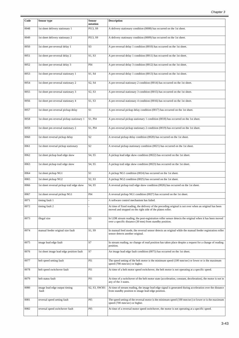
Chapter 3
3-43
0048 1st sheet delivery stationary 1 PI13, S9 A delivery stationary condition (0008) has occurred on the 1st sheet.
0049 1st sheet delivery stationary 2 PI13, S9 A delivery stationary condition (0009) has occurred on the 1st sheet.
0050 1st sheet pre-reversal delay 1 S3 A pre-reversal delay 1 condition (0010) has occurred on the 1st sheet.
0051 1st sheet pre-reversal delay 2 S1, S3 A pre-reversal delay 1 condition (0011) has occurred on the 1st sheet.
0052 1st sheet pre-reversal delay 3 PI4 A pre-reversal delay 3 condition (0012) has occurred on the 1st sheet.
0053 1st sheet pre-reversal stationary 1 S1, S4 A pre-reversal delay 1 condition (0013) has occurred on the 1st sheet.
0054 1st sheet pre-reversal stationary 2 S2, S4 A pre-reversal stationary 2 condition (0014) has occurred on the 1st sheet.
0055 1st sheet pre-reversal stationary 3 S2, S3 A pre-reversal stationary 3 condition (0015) has occurred on the 1st sheet.
0056 1st sheet pre-reversal stationary 4 S1, S3 A pre-reversal stationary 4 condition (0016) has occurred on the 1st sheet.
0057 1st sheet pre-reversal pickup delay S1 A pre-reversal pickup delay condition (0017) has occurred on the 1st sheet.
0058 1st sheet pre-reversal pickup stationary 1 S1, PI4 A pre-reversal pickup stationary 1 condition (0018) has occurred on the 1st sheet.
0059 1st sheet pre-reversal stationary 2 S1, PI4 A pre-reversal pickup stationary 2 condition (0019) has occurred on the 1st sheet.
0060 1st sheet reversal pickup delay S2 A reversal pickup delay condition (0020) has occurred on the 1st sheet.
0061 1st sheet reversal pickup stationary S2 A reversal pickup stationary condition (0021) has occurred on the 1st sheet.
0062 1st sheet pickup lead edge skew S4, S5 A pickup lead edge skew condition (0022) has occurred on the 1st sheet.
0063 1st sheet pickup trail edge skew S4, S5 A pickup trail edge skew condition (0023) has occurred on the 1st sheet.
0064 1st sheet pickup NG1 S1 A pickup NG1 condition (0024) has occurred on the 1st sheet.
0065 1st sheet pickup NG2 S2, S3 A pickup NG2 condition (0025) has occurred on the 1st sheet.
0066 1st sheet reversal pickup trail edge skew S4, S5 A reversal pickup trail edge skew condition (0026) has occurred on the 1st sheet.
0067 1st sheet reversal pickup NG1 PI4 A reversal pickup NG1 condition (0027) has occurred on the 1st sheet.
0071 timing fault 1 - A software control mechanism has failed.
0072 timing fault 2 - At time of fixed reading, the delivery of the preceding original is not over when an original has been moved and stopped on the right side of the platen roller.
0073 illegal size S3 In LDR stream reading, the post-registration roller sensor detects the original when it has been moved over a specific distance (30 mm) from standby position.
0074 manual feeder original size fault S1, S9 In manual feed mode, the reversal sensor detects an original while the manual feeder registration roller sensor detects another original.
0075 image lead edge fault S7 In stream reading, no change of read position has taken place despite a request for a change of reading position.
0076 1st sheet image lead edge position fault S7 An image lead edge fault condition (0075) has occurred on the 1st sheet.
0077 belt speed setting fault PI1 The speed setting of the belt motor is the minimum speed (100 mm/sec) or lower or is the maximum speed (700 mm/sec) or higher.
0078 belt speed switchover fault PI1 At time of a belt motor speed switchover, the belt motor is not operating at a specific speed.
0079 belt status fault PI1 At time of a switchover of the belt motor state (acceleration, constant, deceleration), the motor is not in any of the 3 states.
0080 image lead edge output timing fault
S2, S3, SW301 At time of stream reading, the image lead edge signal is generated during acceleration over the distance from standby position to image lead edge position.
0081 reversal speed setting fault PI5 The speed setting of the reversal motor is the minimum speed (100 mm/sec) or lower or is the maximum speed (700 mm/sec) or higher.
0082 reversal speed switchover fault PI5 At time of a reversal motor speed switchover, the motor is not operating at a specific speed.
Code Sensor type Sensor notation
Description

Chapter 3
3-44
3.7.3 Alarm Code0013-3522
T-3-15
3.8 Power Supply
3.8.1 Overview0013-3523
The following is a diagram of the machine's power supply system:The machine is supplied with 24V and 13V power by its host machine. The 24V power is supplied to various loads by way of a circuit breaker (CB1). Of the 24Vpower supplied to the loads, 24U is sent by way of a fuse, while 24R is sent directly.The 13 V power is converted into 5 V for sensors by a regulator IC (IC15). Another regulator IC (IC26) is used to convert 5 V into 3.3 V, which is used to drivethe ADF controller PCB.
0083 reversal status fault PI5 At time of a switchover of the motor state (acceleration, constant, deceleration), the motor is not in any of the 3 settings.
0084 last original error PI1 While the last original is being discharged from the platen roller or is being moved, a belt motor error has occurred.
0085 error PI1, PI2, PI11 A motor error other than an IPC communication/pickup error has occurred. (less than 3 occurrences)
0090 ADF open PI10 An ADF open condition has been detected.
0091 user DF open PI10 An ADF open condition has been detected while the machine is in operation.
0092 cover open PI3, PI6 A cover open condition (front or rear) has been detected.
0093 user cover open PI3, PI6 While the machine is operating, a sensor in the paper path has detected an original.
0094 initial stationary PI4, PI12, PI13, S1, S2, S3, S4, S5, S9
At the start of operation, the presence of an original has been detected by a senser in the paper path.
0095 cycle NG S6 While no sensor is on, the pickup signal is received for a specific time (2 sec).
0096 residual original S1 Before the start of a left pickup job, the reversal sensor has detected an original while the belt motor is being driven for a specific time.
0097 manual feeder residual original S1, S9 At time of manual feed pickup, the reversal sensor detects an original while the manual feeder registration roller sensor also detects an original.
0098 power-down - While the machine is operating, a drop has occurred in the voltage of the power supplied by the host machine.
Code Name Description
03 separation fault a jam caused by the 1st original not reaching the post-separation sensor a jam caused by the 1st original not reaching the registration sensor
11 decrease in number of originals after jam recovery
a condition caused by a decrease in the number of originals in the tray before delivery of as many as [originals to be recovered - 1] have been delivered at time of jam recovery
21 mode fault selection of mode not permitting execution
Code Sensor type Sensor notation
Description

Chapter 3
3-45
F-3-125[1] Host machine[2] ADF controller PCB[3] Motors, clutches, solenoids[4] Sensors
CB1
IC153.3V
FU6IC26
6
1J4
J1
24V
FU2
5R
24R
24U
5V
13V
[2]


Chapter 4 Parts Replacement Procedure


Contents
Contents
4.1 Removing from the Host Machine.................................................................................................................................4-14.1.1 Feeder........................................................................................................................................................................................... 4-1
4.1.1.1 Disconnecting the DADF................................................................................................................................................................................4-14.2 External Covers..............................................................................................................................................................4-1
4.2.1 External Covers............................................................................................................................................................................ 4-14.2.1.1 External Covers ...............................................................................................................................................................................................4-1
4.2.2 Front Cover .................................................................................................................................................................................. 4-14.2.2.1 Removing the Front Cover..............................................................................................................................................................................4-1
4.2.3 Main Cover .................................................................................................................................................................................. 4-14.2.3.1 Removing the Main Cover ..............................................................................................................................................................................4-1
4.2.4 ADF Controller Cover ................................................................................................................................................................. 4-24.2.4.1 Removing the ADF Controller Cover .............................................................................................................................................................4-2
4.2.5 Side Guide Lock .......................................................................................................................................................................... 4-24.2.5.1 Side Guide Lock..............................................................................................................................................................................................4-2
4.3 Drive System..................................................................................................................................................................4-24.3.1 Reversal Motor............................................................................................................................................................................. 4-2
4.3.1.1 Preparation for Removing the Reversal Motor Unit .......................................................................................................................................4-24.3.1.2 Removing the Reversal Motor Unit ...............................................................................................................................................................4-2
4.3.2 Pickup Motor ............................................................................................................................................................................... 4-34.3.2.1 Preparation for Removing the Pickup Motor Unit ..........................................................................................................................................4-34.3.2.2 Removing the Pickup Motor Unit ..................................................................................................................................................................4-3
4.3.3 Delivery Motor............................................................................................................................................................................. 4-34.3.3.1 Preparation for Removing the Delivery Motor ...............................................................................................................................................4-34.3.3.2 Removing the Delivery Motor ........................................................................................................................................................................4-4
4.3.4 Belt Motor Unit............................................................................................................................................................................ 4-44.3.4.1 Preparation for Removing the Belt Motor Unit ..............................................................................................................................................4-44.3.4.2 Removing the Belt Motor Unit .......................................................................................................................................................................4-4
4.4 Document Feeding System ............................................................................................................................................4-44.4.1 Registration Roller ....................................................................................................................................................................... 4-4
4.4.1.1 Preparation for Removing the Registration Roller..........................................................................................................................................4-44.4.1.2 Removing the Registration Roller...................................................................................................................................................................4-4
4.4.2 Reversing Roller .......................................................................................................................................................................... 4-54.4.2.1 Preparation for Removing the Reversing Roller .............................................................................................................................................4-54.4.2.2 Removing the Reversing Roller ......................................................................................................................................................................4-5
4.4.3 Feed Belt ...................................................................................................................................................................................... 4-64.4.3.1 Preparation for Removing the Feeding Belt....................................................................................................................................................4-64.4.3.2 Removing the Feeding Belt.............................................................................................................................................................................4-64.4.3.3 Attaching the Feeding Belt..............................................................................................................................................................................4-6
4.4.4 Separation Belt............................................................................................................................................................................. 4-74.4.4.1 Preparation for Removing the Separation Belt ...............................................................................................................................................4-74.4.4.2 Removing the Separation Belt ........................................................................................................................................................................4-7
4.4.5 Delivery Roller............................................................................................................................................................................. 4-84.4.5.1 Preparation for Removing the Delivery Roller ...............................................................................................................................................4-84.4.5.2 Removing the Delivery Roller ........................................................................................................................................................................4-8
4.4.6 Pickup Rollor ............................................................................................................................................................................... 4-94.4.6.1 Removing the Pickup Roller ...........................................................................................................................................................................4-9
4.4.7 Separation Rollor ....................................................................................................................................................................... 4-104.4.7.1 Preparation for Removing the Separation Roller ..........................................................................................................................................4-104.4.7.2 Removing the Separation Roller ...................................................................................................................................................................4-10
4.4.8 Feeding (pull-off) Roller............................................................................................................................................................ 4-114.4.8.1 Preparation for Removing the Feeding (pull-off) Roller ..............................................................................................................................4-114.4.8.2 Removing the Feeding (pull-off) Roller .......................................................................................................................................................4-11
4.4.9 Document Tray .......................................................................................................................................................................... 4-12

Contents
4.4.9.1 Removing the Original Tray ......................................................................................................................................................................... 4-124.4.10 Manual Feed Registration Roller ............................................................................................................................................. 4-12
4.4.10.1 Preparation for Removing the Manual Feed Registration ......................................................................................................................... 4-124.4.10.2 Removing the Manual Feed Registration Roller ....................................................................................................................................... 4-13

Chapter 4
4-1
4.1 Removing from the Host Machine
4.1.1 Feeder
4.1.1.1 Disconnecting the DADF0013-3525
1) Turn off the copier.2) Disconnect the DADF's communication cable [1] from the copier.
F-4-13) Open the DADF fully.4) Standing at the rear of the copier, lift the DADF to detach.
F-4-2
4.2 External Covers
4.2.1 External Covers
4.2.1.1 External Covers0013-3526
[1] Body front cover[2] Main cover[3] Original tray[4] Upper cover[5] ADF controller cover
F-4-3
4.2.2 Front Cover
4.2.2.1 Removing the Front Cover0013-3527
1) Remove the front cover [1].- 3 screws [2] (remove)- 1 screw [3] (loosen)
F-4-4
F-4-5
F-4-6
4.2.3 Main Cover
4.2.3.1 Removing the Main Cover0013-3529
1) Open the upper cover, and insert a screwdriver from above the hook; then,remove the two hooks [1].
F-4-72) Free the hook of the pickup assembly cover [2] from the right stay; then,
detach it while paying attention to the hooks on the front and rear sideplates.
[1]
Lift
[5]
[1]
[4]
[3][2]
[1]
[1]
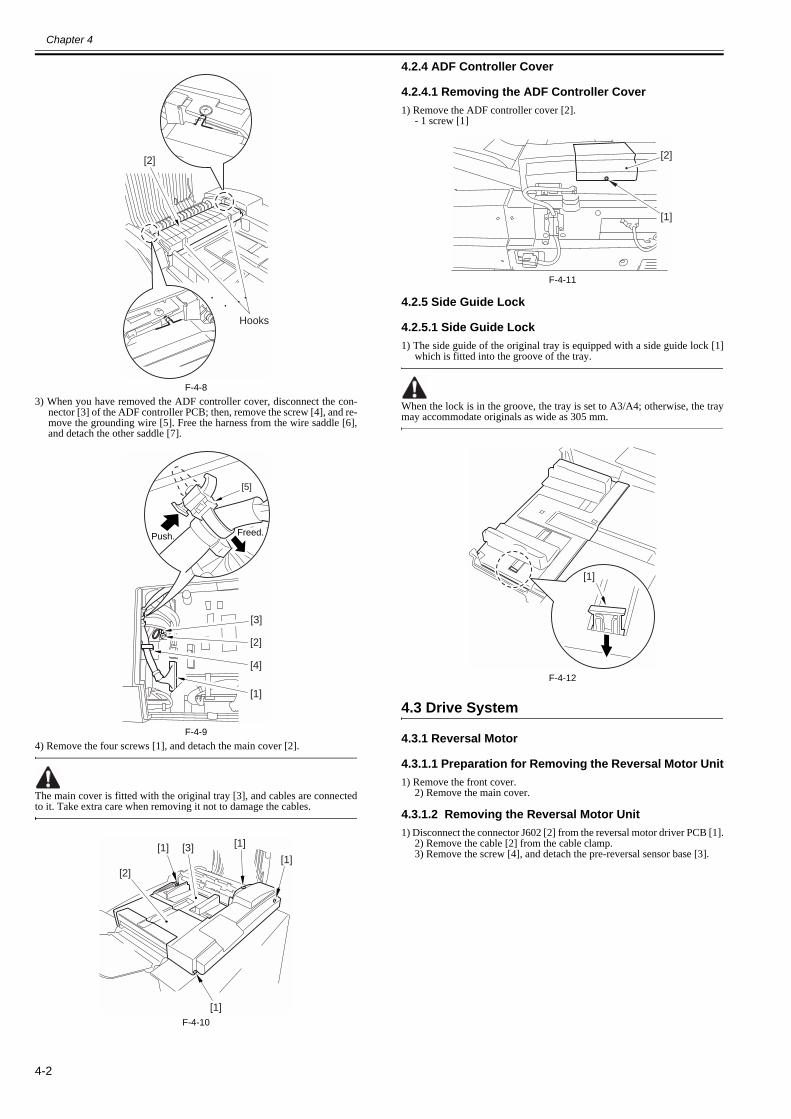
Chapter 4
4-2
F-4-83) When you have removed the ADF controller cover, disconnect the con-
nector [3] of the ADF controller PCB; then, remove the screw [4], and re-move the grounding wire [5]. Free the harness from the wire saddle [6],and detach the other saddle [7].
F-4-94) Remove the four screws [1], and detach the main cover [2].
The main cover is fitted with the original tray [3], and cables are connectedto it. Take extra care when removing it not to damage the cables.
F-4-10
4.2.4 ADF Controller Cover
4.2.4.1 Removing the ADF Controller Cover0012-8791
1) Remove the ADF controller cover [2].- 1 screw [1]
F-4-11
4.2.5 Side Guide Lock
4.2.5.1 Side Guide Lock0012-8792
1) The side guide of the original tray is equipped with a side guide lock [1]which is fitted into the groove of the tray.
When the lock is in the groove, the tray is set to A3/A4; otherwise, the traymay accommodate originals as wide as 305 mm.
F-4-12
4.3 Drive System
4.3.1 Reversal Motor
4.3.1.1 Preparation for Removing the Reversal Motor Unit0013-3530
1) Remove the front cover.2) Remove the main cover.
4.3.1.2 Removing the Reversal Motor Unit0013-3535
1) Disconnect the connector J602 [2] from the reversal motor driver PCB [1].2) Remove the cable [2] from the cable clamp. 3) Remove the screw [4], and detach the pre-reversal sensor base [3].
[2]
Hooks
Push. Freed.
[3]
[5]
[2]
[4]
[1]
[1] [1]
[1]
[1]
[3]
[2]
[1]
[2]
[1]
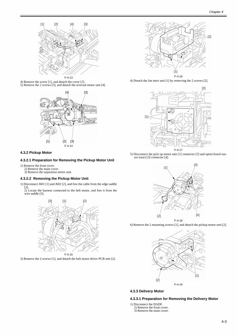
Chapter 4
4-3
F-4-134) Remove the screw [1], and detach the cover [2].5) Remove the 2 screws [3], and detach the reversal motor unit [4].
F-4-14
4.3.2 Pickup Motor
4.3.2.1 Preparation for Removing the Pickup Motor Unit0013-3538
1) Remove the front cover.2) Remove the main cover.3) Remove the separation motor unit.
4.3.2.2 Removing the Pickup Motor Unit0013-3539
1) Disconnect J601 [1] and J602 [2], and free the cable from the edge saddle[3].2) Locate the harness connected to the belt motor, and free it from thewire saddle [3].
F-4-153) Remove the 2 screws [1], and detach the belt motor driver PCB unit [2].
F-4-164) Detach the fan mtor unit [1] by removing the 2 screws [2].
F-4-175) Disconnect the pick up motor unit [1] connecter [2] and open/closed sen-
sor (rear) [3] connecter [4].
F-4-186) Remove the 2 mounting screws [1], and detach the pickup motor unit [2].
F-4-19
4.3.3 Delivery Motor
4.3.3.1 Preparation for Removing the Delivery Motor0013-3541
1) Disconnect the DADF.2) Remove the front cover.3) Remove the main cover.
[1] [2] [3][4]
[1]
[4]
[3]
[3]
[2]
[1] [2][3]
[1]
[2]
[1]
[2]
[2]
[1]
[4]
[3]
[1][2]

Chapter 4
4-4
4.3.3.2 Removing the Delivery Motor0013-3542
1) Remove the screw [1] from the bottom of the DADF, and remove the bear-ing [2] and the rod [3].
F-4-202) Remove the 5 screws [1], and detach the hinge (right) [2].
F-4-213) Remove the screw [1], and detach the delivery motor sensor [2].
F-4-224) Remove the delivery motor.4-1) Remove the grip ring [1], and detach the lock plate [2].
4-2) Remove the E-ring [3], and remove the belt retaining washer [4]and the gear [5].4-3) Remove the screw [6], and detach the delivery motor [7].
F-4-23
If you have replaced the delivery motor, be sure to adjust the sensor and thedelivery motor.
4.3.4 Belt Motor Unit
4.3.4.1 Preparation for Removing the Belt Motor Unit0013-3546
1) Remove the front cover.2) Remove the main cover.3) Remove the separation motor unit.4) Remove the pickup motor unit.
4.3.4.2 Removing the Belt Motor Unit0013-3547
1) Remove the 3 screws [1], and detach the belt motor unit [2].
F-4-24
4.4 Document Feeding System
4.4.1 Registration Roller
4.4.1.1 Preparation for Removing the Registration Roller0013-3555
1) Remove the front cover.2) Remove the main cover.
4.4.1.2 Removing the Registration Roller0013-3557
1) Remove the 2 screws [1], and detach the reversing guide [2].
When mounting the reversing guide, do so while forcing it in the direction ofthe arrow. If not mounted properly, it can trigger jams.
F-4-252) Remove the 2 screws [1], and detach the registration sensor PCB [2].
[2] [3] [1]
[1]
[1][1] [2]
[1]
[1]
[2][1]
[6][2]
[5]
[3][4]
[7]
[1]
[1]
[1][2]
[1]
[1] [2]
Only when mounting it.
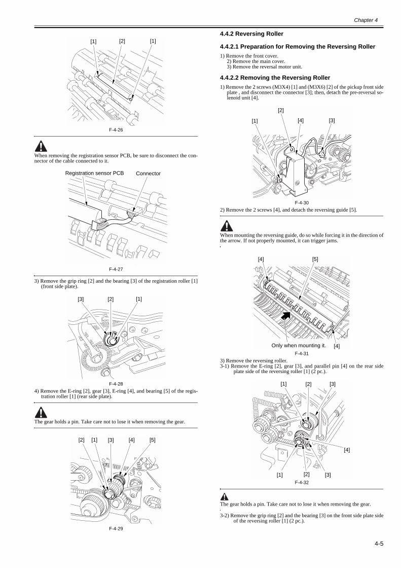
Chapter 4
4-5
F-4-26
When removing the registration sensor PCB, be sure to disconnect the con-nector of the cable connected to it.
F-4-27
3) Remove the grip ring [2] and the bearing [3] of the registration roller [1](front side plate).
F-4-284) Remove the E-ring [2], gear [3], E-ring [4], and bearing [5] of the regis-
tration roller [1] (rear side plate).
The gear holds a pin. Take care not to lose it when removing the gear.
F-4-29
4.4.2 Reversing Roller
4.4.2.1 Preparation for Removing the Reversing Roller0013-3559
1) Remove the front cover.2) Remove the main cover.3) Remove the reversal motor unit.
4.4.2.2 Removing the Reversing Roller0013-3560
1) Remove the 2 screws (M3X4) [1] and (M3X6) [2] of the pickup front sideplate , and disconnect the connector [3]; then, detach the pre-reversal so-lenoid unit [4].
F-4-302) Remove the 2 screws [4], and detach the reversing guide [5].
When mounting the reversing guide, do so while forcing it in the direction ofthe arrow. If not properly mounted, it can trigger jams.
F-4-313) Remove the reversing roller.3-1) Remove the E-ring [2], gear [3], and parallel pin [4] on the rear side
plate side of the reversing roller [1] (2 pc.).
F-4-32
The gear holds a pin. Take care not to lose it when removing the gear.
3-2) Remove the grip ring [2] and the bearing [3] on the front side plate sideof the reversing roller [1] (2 pc.).
[1][1] [2]
Registration sensor PCB Connector
[1][3] [2]
[2] [1] [3] [4] [5]
[3][1]
[2]
[4]
[4]
[4] [5]
Only when mounting it.
[2]
[2] [3]
[3]
[4]
[1]
[1]

Chapter 4
4-6
F-4-333-3) Remove the E-ring [4] and the bearing [5] on the rear side plate side of
the reversing roller [1] (2 pc.).
F-4-343-4) Pull out the reversing roller [1].
4.4.3 Feed Belt
4.4.3.1 Preparation for Removing the Feeding Belt0013-3563
1) Remove the front cover.
4.4.3.2 Removing the Feeding Belt0013-3565
1) Turn the releasing lever [1] clockwise to decrease the tension of the belt.
F-4-352) Turn the releasing levers (left/right) [1] outward after removing the 2 fix-
ing screws [2] each.
F-4-36
F-4-373) Detach the feeding belt [1].
F-4-38
4.4.3.3 Attaching the Feeding Belt0013-3564
1) Insert a screwdriver between the DADF and the feeding assembly asshown to increase the gap.2) Fit in the feeding belt, and pull out the screwdriver when the belt hascome into contact with it; then, push in the belt.
[2]
[2]
[3] [1]
[3] [1]
[5]
[4]
[1]
[1]
[4]
[5]
[1]
[2] [1]
[2][1]
[1]

Chapter 4
4-7
F-4-39
4.4.4 Separation Belt
4.4.4.1 Preparation for Removing the Separation Belt0013-3566
1) Remove the front cover.2) Remove the main cover.
4.4.4.2 Removing the Separation Belt0013-3567
1) Remove the 2 screws, and loosen the separation unit.2) Remove the grip ring [1] at the front; then, remove the clutch ring [2]and the clutch [3].
F-4-403) Disconnect the 2 connectors [1], and remove the 2 screws [2]; then, detach
the separation unit [3].
F-4-41
F-4-424) Remove the 2 mounting screws [1], and detach the separation auxiliary
plate [2].
F-4-435) Loosen the screw [3] on the separation pressure adjusting lever [2] of the
separation roller [3].
F-4-44
When mounting the separation pressure adjusting lever, be sure that the leveris set to low.
F-4-45
6) Loosen the screw [3] on the thrust stopper [2] of the separation roller [1].
[3]
[2][1]
[3]
[2][1]
[2][3]
[1][1] [2]
[3] [1] [2]
"High" "Low"

Chapter 4
4-8
F-4-467) Remove the E-ring [2] and the gear [3] at the rear of the separation roller
[1].
The gear holds a pin. Take care not to lose it when removing the gear.
F-4-478) Remove the E-ring [2] at the rear of the separation roller [1] to detach the
separation belt [3].
F-4-48
4.4.5 Delivery Roller
4.4.5.1 Preparation for Removing the Delivery Roller0013-3568
1) Disconnect the DADF.2) Remove the front cover.3) Remove the main cover.
4.4.5.2 Removing the Delivery Roller0013-3569
1) Remove the screw [1] from the bottom of the DADF, and remove the bear-ing [2] and the rod [3].
F-4-492) Remove the 5 screws [1], and detach the hinge (right) [2].
F-4-503) Remove the E-ring [1], and detach the solenoid link arm [2].
F-4-514) Remove the screw [1], and detach the delivery guide plate [2].
5) Remove the screw [3], and free the grounding wire [4] of the staticeliminator attached to the delivery guide.
F-4-526) Remove the 3 screws [1], and disconnect the connector [2]; then, detach
the solenoid unit [3] from the delivery assembly front side plate.
[2][1] [3]
[1][2][3]
[2]
[3]
[1]
[2] [3] [1]
[1]
[1][1] [2]
[1]
[1]
[1] [2]
[1] [2]
[4] [3]

Chapter 4
4-9
F-4-537) Remove the screw [1], and detach the delivery sensor support plate [2] on
the delivery assembly rear side plate side.
F-4-548) Remove the screw [1], and detach the delivery guide support plate [2] on
the delivery assembly rear side plate side.
F-4-559) Remove the screw [1], and detach the delivery lower guide support plate
[2] on the delivery assembly front plate side.10) Remove the E-ring [3] from the delivery assembly front plate side;then, remove the screw [4], and detach the bushing [5].
F-4-5611) Remove the E-ring [1] from the delivery assembly rear side plate side;
then, remove the gear [2] and the parallel pin [3].12) Remove the E-ring [4]; then, remove the screw [5] and the bushing[6].
F-4-5713) Shift down the delivery lower guide [1], and slide out the delivery roller
[2] together with the manual feed tray [3].
F-4-58
4.4.6 Pickup Rollor
4.4.6.1 Removing the Pickup Roller0013-3571
1) Open the upper cover, and insert a screwdriver from above the hook; then,remove the 2 hooks [1].
F-4-592) Remove pickup assembly cover [1].
[1]
[2] [3]
[1]
[1][2]
[2] [1]
[1] [2]
[3]
[5]
[4]
[1] [2][6] [4] [5] [3]
[3][1] [2]
[1]
[1]

Chapter 4
4-10
F-4-603) Remove the resin E-ring [1]; then, remove the roller arm [2], and detach
the pickup roller [3].
F-4-61
4.4.7 Separation Rollor
4.4.7.1 Preparation for Removing the Separation Roller0013-3572
1) Remove the front cover.2) Remove the main cover.
4.4.7.2 Removing the Separation Roller0013-3573
1) Remove the 2 screws [1], and detach the sensor stay [2].2) Remove the 3 screws [3], and detach the 3 guide plates [5] from theright stay [4].
F-4-623) Remove the 2 screws [1], and detach the lower guide [2].
F-4-63
F-4-644) Remove the grip ring [1] on the front side plate side, and pull out the clutch
ring [2].
F-4-655) Remove the screw [2] of the gear support plate (front) [1]; then, shift the
gear support plate (front) [1] to the left to pull out the clutch [3] to thefront.
The clutch has 2 stoppers. Use the white stopper when re-assmbling.
F-4-666) Disconnect the 2 connectors [1], and remove the 2 mounting screws [2];
then, detach the separation unit [3].
[2]
Free the claws,and detach the cover.
[1] [2] [3]
[1][1]
[2]
[4][5]
[5]
[5][3]
[3]
[3]
[1][2]
[2][1]
[2][1]
[1][2] [3]

Chapter 4
4-11
F-4-67
F-4-687) Remove the E-ring [1], and pull out the shaft [2].
F-4-698) Remove the grip ring [1] at the front, and remove the bushing [2].
F-4-709) Remove the E-ring [1] and the bushing [2] at the rear, and detach the rod
arm plate [3].
F-4-7110) Remove the E-ring [1] and the one-way gear [2] at the rear.
F-4-7211) Remove the separation roller.
When mounting the one-way gear, be sure that the protrusion faces inside.
F-4-73
4.4.8 Feeding (pull-off) Roller
4.4.8.1 Preparation for Removing the Feeding (pull-off) Roller
0013-3574
1) Remove the front cover.2) Remove the main cover.
4.4.8.2 Removing the Feeding (pull-off) Roller0013-3575
1) Remove the mounting screw [2] of the gear support plate [1] of the pickupfront side plate.
[3]
[2][1]
[2][3]
[1] [2]
[1][2]
[3] [2]
[1]
[1] [2]
One-way gear Protrusion

Chapter 4
4-12
F-4-742) Remove the E-ring [1], washer [2], 2 shims [3], gear (black) [4], gear
(white) [5], 2 shims [6], and spring [7] in sequence.
F-4-753) Remove the gear support plate of the front side plate.
4) Remove the E-ring [2], gear [3], parallel pin [4], grip ring [5], and bear-ing [6] of the feeding (pull-off) roller [1] (front side plate).
F-4-765) Remove the E-ring [2], gear [3], parallel pin [4], E-ring [5], and bearing
[6] of the feeding (pull-off) roller [1] (rear side plate); then, remove thefeeding (pull-off) roller [1].
The gear holds a pin. Take care not to drop it.
F-4-77
4.4.9 Document Tray
4.4.9.1 Removing the Original Tray0013-3576
1) Remove the ADF controller cover.2) Disconnect the connector [1] of the ADF controller PCB.3) Free the harness from the wire saddle [4] and the other saddle [5].4) Remove the screw [2], and remove the grounding wire [3].
F-4-785) Move the side guides (front) [1]/(rear) [2] to the inside; then, remove the
2 screws [3], and detach it.
F-4-79
After mounting it, be sure to adjust the horizontal registration.
4.4.10 Manual Feed Registration Roller
4.4.10.1 Preparation for Removing the Manual Feed Registration
0013-3578
1) Remove the front cover.2) Remove the main cover.
[1][2]
[1]
[5]
[6]
[4][3]
[3]
[2]
[2][3][1][5][6] [4]
[6] [5] [4] [1] [2]
[3]
Push. Freed.
[3]
[5]
[2]
[4]
[1]
[3][1]
[2]
[3]

Chapter 4
4-13
4.4.10.2 Removing the Manual Feed Registration Roller0013-3579
1) Remove the 3 screws [1], and disconnect the connector [2]; then, removethe solenoid unit [3] from the delivery assembly front side plate.
F-4-802) Remove the 2 screws [1], and detach the manual feed registration sensor
PCB assembly [2].
F-4-813) Remove the grip ring [2] and the bearing [3] from the manual feed regis-
tration roller [1]. (delivery assembly front side plate)
F-4-824) Remove the grip ring [2] of the manual feed registration roller [1].5) Remove the E-ring [4] of the feeding belt roller shaft [3].6) Remove the gear [5] and the parallel pin [6].7) Remove the gear unit [6] and the bushing [8].
F-4-83
8) Remove the E-ring [2] and the bearing [3] from the delivery assembly rearplate; then, pull out the manual feed registration roller [1].
F-4-84
[1]
[2] [3]
[1]
[1] [2]
[2][1][3]
[3]
[8] [7]
[4][2] [1]
[6]
[5]
[1][3] [2]


Chapter 5 Maintenance

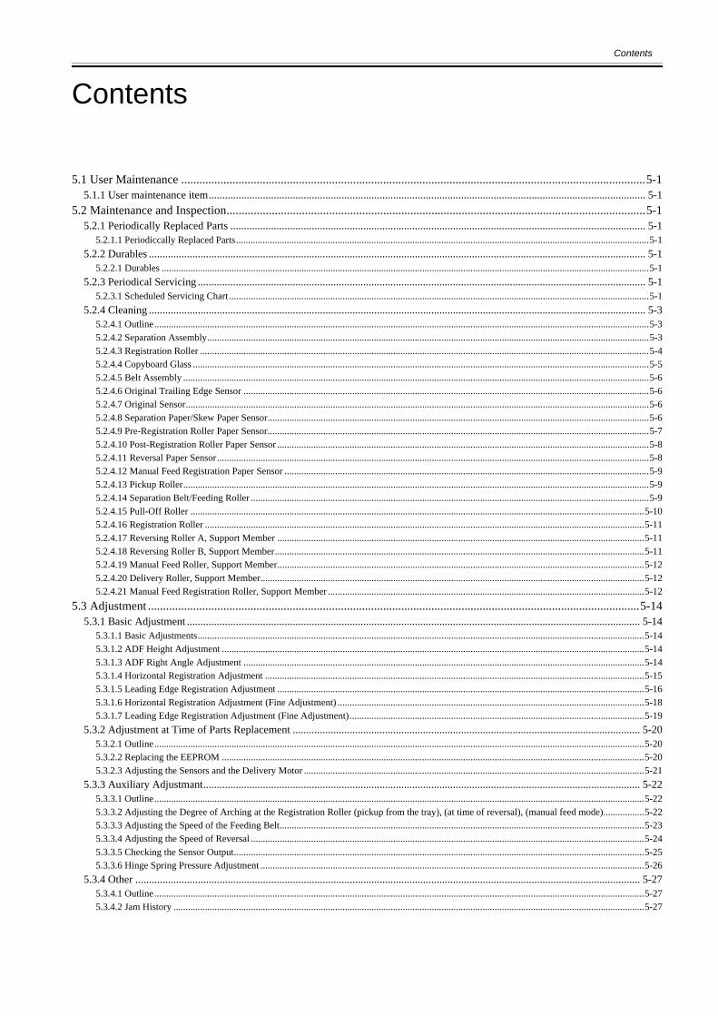
Contents
Contents
5.1 User Maintenance ..........................................................................................................................................................5-15.1.1 User maintenance item................................................................................................................................................................. 5-1
5.2 Maintenance and Inspection...........................................................................................................................................5-15.2.1 Periodically Replaced Parts ......................................................................................................................................................... 5-1
5.2.1.1 Periodiccally Replaced Parts...........................................................................................................................................................................5-15.2.2 Durables ....................................................................................................................................................................................... 5-1
5.2.2.1 Durables ..........................................................................................................................................................................................................5-15.2.3 Periodical Servicing ..................................................................................................................................................................... 5-1
5.2.3.1 Scheduled Servicing Chart ..............................................................................................................................................................................5-15.2.4 Cleaning ....................................................................................................................................................................................... 5-3
5.2.4.1 Outline.............................................................................................................................................................................................................5-35.2.4.2 Separation Assembly.......................................................................................................................................................................................5-35.2.4.3 Registration Roller ..........................................................................................................................................................................................5-45.2.4.4 Copyboard Glass .............................................................................................................................................................................................5-55.2.4.5 Belt Assembly .................................................................................................................................................................................................5-65.2.4.6 Original Trailing Edge Sensor ........................................................................................................................................................................5-65.2.4.7 Original Sensor................................................................................................................................................................................................5-65.2.4.8 Separation Paper/Skew Paper Sensor..............................................................................................................................................................5-65.2.4.9 Pre-Registration Roller Paper Sensor..............................................................................................................................................................5-75.2.4.10 Post-Registration Roller Paper Sensor ..........................................................................................................................................................5-85.2.4.11 Reversal Paper Sensor...................................................................................................................................................................................5-85.2.4.12 Manual Feed Registration Paper Sensor .......................................................................................................................................................5-95.2.4.13 Pickup Roller.................................................................................................................................................................................................5-95.2.4.14 Separation Belt/Feeding Roller .....................................................................................................................................................................5-95.2.4.15 Pull-Off Roller ............................................................................................................................................................................................5-105.2.4.16 Registration Roller ......................................................................................................................................................................................5-115.2.4.17 Reversing Roller A, Support Member ........................................................................................................................................................5-115.2.4.18 Reversing Roller B, Support Member.........................................................................................................................................................5-115.2.4.19 Manual Feed Roller, Support Member........................................................................................................................................................5-125.2.4.20 Delivery Roller, Support Member...............................................................................................................................................................5-125.2.4.21 Manual Feed Registration Roller, Support Member ...................................................................................................................................5-12
5.3 Adjustment ...................................................................................................................................................................5-145.3.1 Basic Adjustment ....................................................................................................................................................................... 5-14
5.3.1.1 Basic Adjustments.........................................................................................................................................................................................5-145.3.1.2 ADF Height Adjustment ...............................................................................................................................................................................5-145.3.1.3 ADF Right Angle Adjustment ......................................................................................................................................................................5-145.3.1.4 Horizontal Registration Adjustment .............................................................................................................................................................5-155.3.1.5 Leading Edge Registration Adjustment ........................................................................................................................................................5-165.3.1.6 Horizontal Registration Adjustment (Fine Adjustment) ...............................................................................................................................5-185.3.1.7 Leading Edge Registration Adjustment (Fine Adjustment)..........................................................................................................................5-19
5.3.2 Adjustment at Time of Parts Replacement ................................................................................................................................ 5-205.3.2.1 Outline...........................................................................................................................................................................................................5-205.3.2.2 Replacing the EEPROM ...............................................................................................................................................................................5-205.3.2.3 Adjusting the Sensors and the Delivery Motor .............................................................................................................................................5-21
5.3.3 Auxiliary Adjustmant................................................................................................................................................................. 5-225.3.3.1 Outline...........................................................................................................................................................................................................5-225.3.3.2 Adjusting the Degree of Arching at the Registration Roller (pickup from the tray), (at time of reversal), (manual feed mode).................5-225.3.3.3 Adjusting the Speed of the Feeding Belt.......................................................................................................................................................5-235.3.3.4 Adjusting the Speed of Reversal ...................................................................................................................................................................5-245.3.3.5 Checking the Sensor Output..........................................................................................................................................................................5-255.3.3.6 Hinge Spring Pressure Adjustment ...............................................................................................................................................................5-26
5.3.4 Other .......................................................................................................................................................................................... 5-275.3.4.1 Outline...........................................................................................................................................................................................................5-275.3.4.2 Jam History ...................................................................................................................................................................................................5-27

Contents
5.3.4.3 Version of the Software ................................................................................................................................................................................ 5-275.3.4.4 Checking the Original Width ........................................................................................................................................................................ 5-285.3.4.5 Resetting the Backup RAM .......................................................................................................................................................................... 5-28
5.4 Troubleshooting........................................................................................................................................................... 5-305.4.1 Error Code.................................................................................................................................................................................. 5-30
5.4.1.1 E402 display lamp ........................................................................................................................................................................................ 5-305.4.1.2 E404 display lamp ........................................................................................................................................................................................ 5-305.4.1.3 E405 display lamp ........................................................................................................................................................................................ 5-305.4.1.4 E410 display lamp ........................................................................................................................................................................................ 5-315.4.1.5 E420 display lamp ........................................................................................................................................................................................ 5-31
5.4.2 Alarm Code................................................................................................................................................................................ 5-325.4.2.1 Alarm ............................................................................................................................................................................................................ 5-32
5.5 Outline of Electrical Components ............................................................................................................................... 5-325.5.1 Sensors ....................................................................................................................................................................................... 5-325.5.2 Motors, Clutches, and Solenoids ............................................................................................................................................... 5-335.5.3 PCBs .......................................................................................................................................................................................... 5-34
5.6 Variable Resistors (VR), Light-Emitting Diodes (LED), and Check Pins by PCB .................................................... 5-345.6.1 Outline........................................................................................................................................................................................ 5-345.6.2 ADF Controller PCB.................................................................................................................................................................. 5-345.6.3 DIP Switch Functions ................................................................................................................................................................ 5-355.6.4 Reversal Motor Driver PCB/ Belt Motor Driver PCB............................................................................................................... 5-385.6.5 Pickup Tray PCB ....................................................................................................................................................................... 5-385.6.6 Indication LED PCB.................................................................................................................................................................. 5-38
5.7 Upgrading.................................................................................................................................................................... 5-385.7.1 Before upgrading system software............................................................................................................................................. 5-385.7.2 Upgrade Procedure..................................................................................................................................................................... 5-40
5.8 Service Tools ............................................................................................................................................................... 5-415.8.1 Special Tools List ...................................................................................................................................................................... 5-415.8.2 Solvents and Oils List ................................................................................................................................................................ 5-42

Chapter 5
5-1
5.1 User Maintenance
5.1.1 User maintenance item0013-3772
T-5-1
5.2 Maintenance and Inspection
5.2.1 Periodically Replaced Parts
5.2.1.1 Periodiccally Replaced Parts0013-3773
This machine dose not have the periodiccally replaced parts.
5.2.2 Durables
5.2.2.1 Durables0013-3774
Some parts of the DADF may require replacement once or more over the period of product warranty because of wear or damage. Replace them as needed by refer-ring to the following guide, in which the life of each part is expressed in terms of the number of originals (may be checked in the copier's service mode).
T-5-2
* Replacement with unit is recommended for No. 3 and 4, however individual part is set up.The actual number of originals handled may be checked in the copier's service mode (COPIER > COUNTER > DRBL-2).
Expected service life shows the central value of a group of evaluation data points. Parts Numbers may subject to change because of design
5.2.3 Periodical Servicing
5.2.3.1 Scheduled Servicing Chart0013-3775
Do not use solvents or oils other than those indicated.
Item Period Substance
Copyboard glass opportune or every 10,000 documents
CleaningCopyboard glass retainer
opportuneFeeding belt
Vertical size plate
No. Part name Part No. Q'ty Estimated life Remarks
1 Feeding belt FC6-0929-000 1 200,000 The time when cleaning is not effective.
2 Pickup roller FB4-7640-000 2 250,000 Replace
3 Pickup/Feeding roller* FM2-2048-000 1 80,000
4 Separation belt* FG6-7724-000 1
5 Hinge (L) FC6-0987-000 1 100,000
6 Hinge (R) FC6-0988-000 1

Chapter 5
5-2
T-5-3
F-5-1The actual number of originals handled may be checked in the copier's service mode (the sum of L-FEED and S-FEED under COPIER > COUNTER > Feeder).
Ref. Part name every 100,000 or 6 mo
every 200,000 or 1 yr Remarks
1 Original training edge sensor (S7) Cleaning Actual volume
2 Original sensor (S6) Cleaning
3 Separation paper sensor (S4) Cleaning
4 Skew paper sensor (S5) Cleaning
5 Pre-registration roller paper sensor (S2)
Cleaning
6 Post-registration roller paper sensor (S3)
Cleaning
7 Reversal paper sensor (S1) Cleaning
8 Manual registration roller paper sensor (S9)
Cleaning
9 Pickup roller Cleaning
10 Feeding roller Cleaning
11 Separation belt Cleaning
12 Pull-off roller Cleaning
13 Registration roller Cleaning
14 Reversing roller A, member Cleaning
15 Reversing roller B, member Cleaning
16 Manual feed roller, member Cleaning
17 Delivery roller, member Cleaning
Various slave roller, member Cleaning
[2] Original sensor (S6) [1] Original training edge sensor (S7)
[3] Separation paper sensor (S4)
[4] Skew paper sensor (S5)
[7] Reversal paper sensor (S1)
[9] Pickup roller
[10] Feeding roller[11] Separation belt
[12] Pull-off roller
[13] Registration roller
[5] Pre-registration roller paper sensor (S2)
[6] Post-registration roller paper sensor (S3)
[8] Manual registration roller paper sensor (S9)
[14] Reversing roller A, member
[15] Reversing roller B, member
[17] Delivery roller, member
[16] Manual feed roller, member
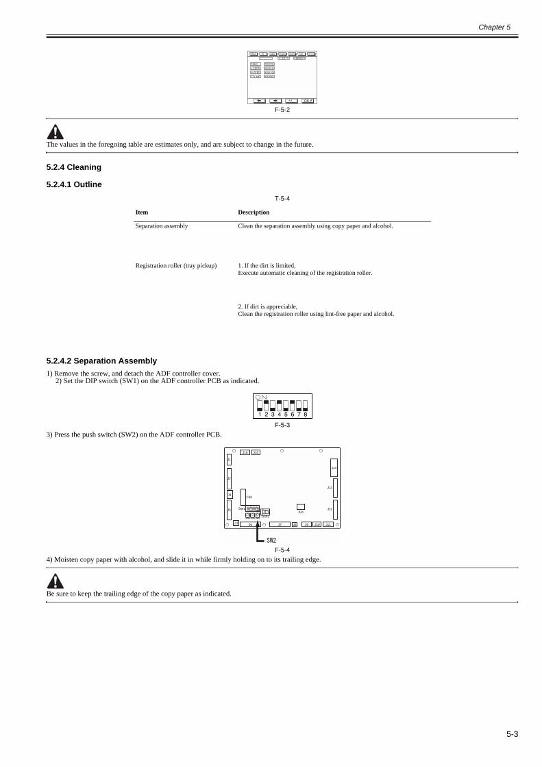
Chapter 5
5-3
F-5-2
The values in the foregoing table are estimates only, and are subject to change in the future.
5.2.4 Cleaning
5.2.4.1 Outline0013-3776
T-5-4
5.2.4.2 Separation Assembly0013-3777
1) Remove the screw, and detach the ADF controller cover.2) Set the DIP switch (SW1) on the ADF controller PCB as indicated.
F-5-33) Press the push switch (SW2) on the ADF controller PCB.
F-5-44) Moisten copy paper with alcohol, and slide it in while firmly holding on to its trailing edge.
Be sure to keep the trailing edge of the copy paper as indicated.
Item Description
Separation assembly Clean the separation assembly using copy paper and alcohol.
Registration roller (tray pickup) 1. If the dirt is limited,Execute automatic cleaning of the registration roller.
2. If dirt is appreciable,Clean the registration roller using lint-free paper and alcohol.
FEED 00000061
00000123
00001763
00000001
L-FEED
S-FEED
TTL-MF
< 1/1 > < READY >
Display I/O Adjust Function Option Test
+/- OK
J1
J2
J5
J3 J6 J7 J8 J9 J10
J16 J15
J11
J14
IC8
J13
J12
J4CB1
SW1
DSP1SW4SW3SW2

Chapter 5
5-4
F-5-5
F-5-65) Press the push switch (SW2) on the ADF controller PCB to end the operation.
5.2.4.3 Registration Roller0013-3778
If the dirt is limited,1) Remove the screw, and detach the ADF controller cover.
2) Set the DIP switch (SW1) on the ADF controller PCB as indicated.
F-5-73) Place about ten sheets of copy paper in the original tray.
4) Press the push switch (SW2) on the ADF controller PCB. The operation will end automatically.
F-5-8
If dirt is appreciable,1) Open the upper cover, and open the feeding guide.
Slide guideRail
For A4,
Butt the end ofpaper.
Slideguide
Rail
For LTR,
Matchthe edge of paper.
J1
J2
J5
J3 J6 J7 J8 J9 J10
J16 J15
J11
J14
IC8
J13
J12
J4CB1
SW1
DSP1SW4SW3SW2
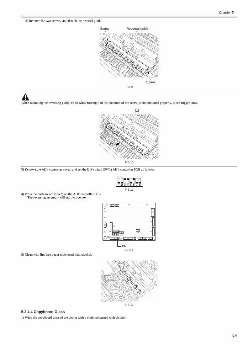
Chapter 5
5-5
2) Remove the two screws, and detach the reversal guide.
F-5-9
When mounting the reversing guide, do so while forcing it in the direction of the arrow. If not mounted properly, it can trigger jams.
F-5-10
3) Remove the ADF controller cover, and set the DIP switch (SW1) ADF controller PCB as follows.
F-5-114) Press the push switch (SW2) on the ADF controller PCB.
- The reversing assembly will start to operate.
F-5-125) Clean with lint-free paper moistened with alcohol.
F-5-13
5.2.4.4 Copyboard Glass0013-3779
1) Wipe the copyboard glass of the copier with a cloth moistened with alcohol.
Screw
Screw Reversal guide
[1]
J1
J2
J5
J3 J6 J7 J8 J9 J10
J16 J15
J11
J14
IC8
J13
J12
J4CB1
SW1
DSP1SW4SW3SW2

Chapter 5
5-6
F-5-14
5.2.4.5 Belt Assembly0013-3780
1) Dry wipe the original feeding belt while moving it in the direction of the arrow.If the dirt is excessive, wipe it with a cloth moistened with a solution of mild detergent; then, dry wipe it.
F-5-15
5.2.4.6 Original Trailing Edge Sensor0013-3781
1) Clean the sensor widow in the original tray using a blower brush.
F-5-16
5.2.4.7 Original Sensor0013-3782
1) Remove the pickup assembly cover.2) Clean the light-receiving area of the sensor stay and the light-emitting area at the rear of the guide plate using a blower brush.
F-5-17
5.2.4.8 Separation Paper/Skew Paper Sensor0013-3783

Chapter 5
5-7
Do not use a solvent (alcoholfamily or ketone family) to clean the prism face.It is made of acrylic resin, and contact with solvent can discolor it, adversely affecting its operation.
1) Open the pickup assembly upper cover.2) Open the registration guide.3) Put the blower brush between the separation stay and the separation guide to clean. (The one to the front is the separation paper sensor, while the one at therear is the skew paper sensor.)
F-5-18
F-5-19
5.2.4.9 Pre-Registration Roller Paper Sensor0013-3784
Do not use a solvent (alcoholfamily or ketone family) to clean the prism face.It is made of acrylic resin, and contact with solvent can discolor it, adversely affecting its operation.
1) Remove the reversing guide.2) Clean the face of the prism behind the reversing guide.
F-5-203) Remove the registration sensor PCB.
4) Clean the 2 filter surfaces of the sensor.
Surface to clean(back)
Surface to clean(face)
Prism
Surface to clean(back)
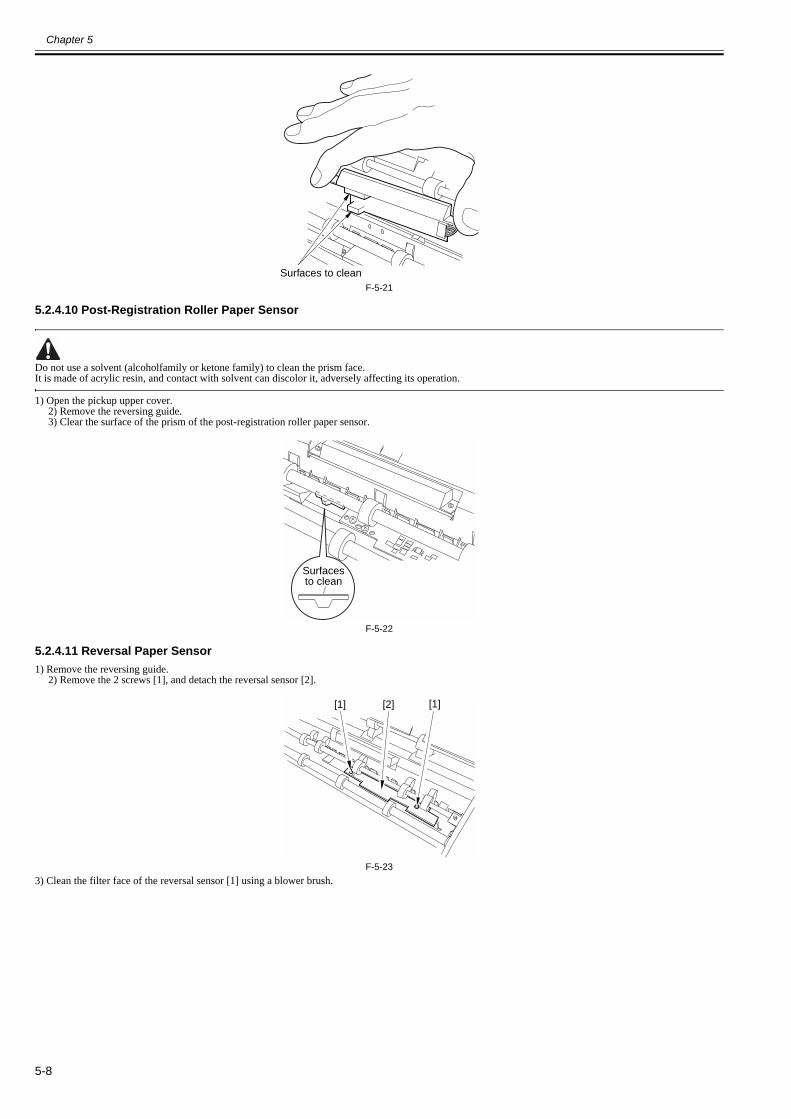
Chapter 5
5-8
F-5-21
5.2.4.10 Post-Registration Roller Paper Sensor0013-3785
Do not use a solvent (alcoholfamily or ketone family) to clean the prism face.It is made of acrylic resin, and contact with solvent can discolor it, adversely affecting its operation.
1) Open the pickup upper cover.2) Remove the reversing guide.3) Clear the surface of the prism of the post-registration roller paper sensor.
F-5-22
5.2.4.11 Reversal Paper Sensor0013-3786
1) Remove the reversing guide.2) Remove the 2 screws [1], and detach the reversal sensor [2].
F-5-233) Clean the filter face of the reversal sensor [1] using a blower brush.
Surfaces to clean
Surfacesto clean
[1][1] [2]

Chapter 5
5-9
F-5-244) Open the DADF fully.
5) While opening the pickup middle guide found to the left of the feeding belt, aim a blower brush against the prism of the reflecting face of the reversal sensorin view in the rear to clean.
F-5-25
5.2.4.12 Manual Feed Registration Paper Sensor0013-3787
1) Remove the body front cover.2) Remove the main cover.3) Aim a blower brush against the detecting hole of the registration sensor on the delivery upper guide to clean.
F-5-26
5.2.4.13 Pickup Roller0013-3788
1) Open the pickup assembly upper cover.2) Remove the pickup cover.3) Clean the surface of the roller using lint-free paper or cloth moistened with alcohol.
F-5-27
5.2.4.14 Separation Belt/Feeding Roller0013-3789
1) Obtain a single sheet of A4 or LTR copy paper.2) Remove the ADF controller cover, and set the DIP switch (SW1) on the ADF controller PCB as indicated.
[1]

Chapter 5
5-10
F-5-283) Press the push switch (SW2) on the ADF controller PCB.
- The separation assembly will start.4) Moisten t the copy paper obtained in step 1) with alcohol.
5) Keep the copy paper against the pickup slot to clean.
The pull-off roller is also driven. Hold the copy paper so that it will not be drawn to the pull-off roller: in the case of A4, as shown in Figure A; in the case of LTR,as shown in Figure B.
F-5-29
F-5-30
6) At the end of cleaning work, press the push switch (SW2) once again.- The separation assembly will stop.
5.2.4.15 Pull-Off Roller0013-3790
1) Open the upper cover, and open the feeding guide.2) Remove the ADF controller cover, and set the DIP switch (SW1) on the ADF controller PCB as indicated.
F-5-313) Press the push switch (SW2) on the ADF controller PCB.
- The separation assembly will start.4) Clean it with lint-free paper moistened with alcohol.
Slide guideRail
Against the edge ofthe paper.
Rail
Againstthe edge of the paper.
Slide guide
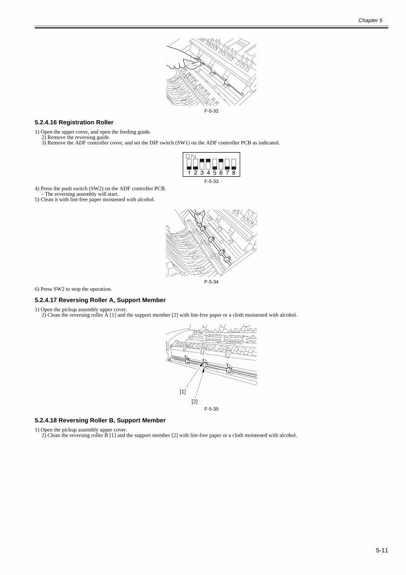
Chapter 5
5-11
F-5-32
5.2.4.16 Registration Roller0013-3792
1) Open the upper cover, and open the feeding guide.2) Remove the reversing guide.3) Remove the ADF controller cover, and set the DIP switch (SW1) on the ADF controller PCB as indicated.
F-5-334) Press the push switch (SW2) on the ADF controller PCB.
- The reversing assembly will start.5) Clean it with lint-free paper moistened with alcohol.
F-5-346) Press SW2 to stop the operation.
5.2.4.17 Reversing Roller A, Support Member0013-3794
1) Open the pickup assembly upper cover.2) Clean the reversing roller A [1] and the support member [2] with lint-free paper or a cloth moistened with alcohol.
F-5-35
5.2.4.18 Reversing Roller B, Support Member0013-3795
1) Open the pickup assembly upper cover.2) Clean the reversing roller B [1] and the support member [2] with lint-free paper or a cloth moistened with alcohol.
[1]
[2]

Chapter 5
5-12
F-5-36
5.2.4.19 Manual Feed Roller, Support Member0013-3796
1) Open the manual feed tray.2) Clean the manual feed (delivery) roller [1] and the support member [2] with lint-free paper or a cloth moistened with alcohol.
F-5-37
5.2.4.20 Delivery Roller, Support Member0013-3797
1) With the manual feed tray closed, clean the delivery (manual feed) roller [1] and the support member [2] with lint-free paper or a cloth moistened with alcohol.
F-5-38
5.2.4.21 Manual Feed Registration Roller, Support Member0013-3798
1) Remove the main cover.2) Remove the 2 screws [1], and the detach the manual feed registration sensor PCB [2].
[1][2]
[1][2]
[1]
[2]

Chapter 5
5-13
F-5-393) Clean the manual feed registration roller [1] with lint-free paper or a cloth mounted with alcohol.
F-5-404) Shift up the DADF.5) Open the delivery lower guide [1].6) Clean the manual feed registration roller member [2] with lint-free paper or a cloth moistened with alcohol.
F-5-41
[1] [2]
[1]
[2]
[1]

Chapter 5
5-14
5.3 Adjustment
5.3.1 Basic Adjustment
5.3.1.1 Basic Adjustments0013-3799
The basic adjustments of the DADF consist of the following, which must beperformed in sequence:[1] ADF height adjustment[2] ADF right angle adjustment[3] Horizontal registration adjustment[4] Leading edge registration adjustment[5] Horizontal registration adjustment (fine adjustment)[6] Leading edge registration adjustment (fine adjustment)
5.3.1.2 ADF Height Adjustment0013-3800
1) Remove the front cover [1].- 3 screws [2] (remove)- 1 screw [3] (loosen)
F-5-42
F-5-43
F-5-442) Make adjustments by loosening the 2 fixed screws [3] on the magnet catch
[2] so that the left and right rubber feet [1] are in contact with the basewhen the DADF is closed.
F-5-453) After the adjustment, tighten the fixing screws on the magnet catch, and
mount the front cover.
5.3.1.3 ADF Right Angle Adjustment0013-3801
Here, the original feed direction of the machine is adjusted in relation to theoptical system of the host machine.1) Prepare a test chart as shown using A4 or LTR copy paper.
F-5-462) Place the test chart [1] prepared above in the original tray, and make a
copy in stream reading mode at 100 % magnification.
F-5-473) Place other copy paper [2] on the image [1] you obtained in step 2), and
check the image for right angles.- A < 1 mm- B < 1 mm
[1] [2] [3][3]
[1][2] [3][3]
Right angle
10mm10mm
10m
m10
mm
[1]

Chapter 5
5-15
F-5-48If not as indicated, go through the following:4) Open the DADF.5) Loosen the fixing nut [1] found at the rear of the right hinge unit, and turn
the adjusting screw [2] to adjust.- If A > 0, turn the adjusting screw counterclockwise.- If B > 0, turn the adjusting screw clockwise.
F-5-496) Tighten the fixing nut to fix the adjusting screw in place.
5.3.1.4 Horizontal Registration Adjustment0013-3815
Horizontal Registration Adjustment for the following 2:- pickup from the original tray- pickup from the manual feeder tray
A. Pickup from the Original Tray1) Remove the DADF controller cover [1].
- 1 screw [2]
F-5-502) Set the DIP switch (SW1) on the DADF controller PCB as follows:
F-5-513) Place a single sheet of A4 or LTR copy paper [1] in the original tray.
F-5-524) Press the push switch (SW2) on the DADF controller PCB once.
-> In response, the original is picked up and stopped on the copyboardglass.
F-5-535) Open the DADF, and check to make sure that C is as indicated.
T-5-5
F-5-546) Close the DADF, and push the push switch (SW2) on the DADF controller
PCB once.-> In response, the original will be discharged to the delivery tray.
7) When done, tighten the original tray fixing screw.8) Put the DIP switch (SW1) of the ADF controller PCB back to its initial
configuration, and mount the ADF controller cover.
< If Not as Indicated >If the dimension is not as indicated, adjust the position of the original tray.1) Loosen the tray fixing screw [1], and adjust the position of the original
tray [2].- If C > 3.1 mm for A4/11.9 for LTR, move the original tray toward therear.- If C < 3.1 mm for A4/11.9 for LTR, move the original tray toward thefront.
A
Feeddirection
Feeddirection
B
[1]
[2]
[2][1]
[2]
[1]
Original size Value of C
A4 3.1 +/- 1 mm
LTR 11.9 +/- 1 mm
J1
J2
J5
J3 J6 J7 J8 J9 J10
J16 J15
J11
J14
IC8
J13
J12
J4CB1
SW1
DSP1SW4SW3SW2
C
Original
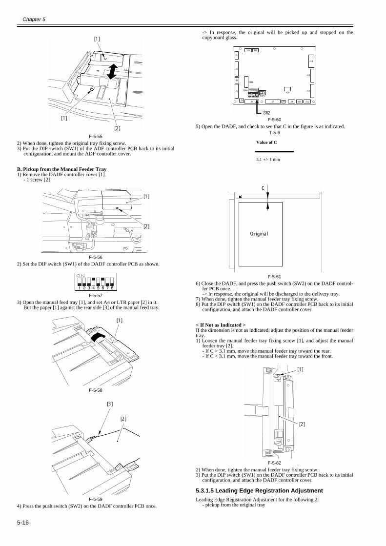
Chapter 5
5-16
F-5-552) When done, tighten the original tray fixing screw.3) Put the DIP switch (SW1) of the ADF controller PCB back to its initial
configuration, and mount the ADF controller cover.
B. Pickup from the Manual Feeder Tray1) Remove the DADF controller cover [1].
- 1 screw [2]
F-5-562) Set the DIP switch (SW1) of the DADF controller PCB as shown.
F-5-573) Open the manual feed tray [1], and set A4 or LTR paper [2] in it.
But the paper [1] against the rear side [3] of the manual feed tray.
F-5-58
F-5-594) Press the push switch (SW2) on the DADF controller PCB once.
-> In response, the original will be picked up and stopped on thecopyboard glass.
F-5-605) Open the DADF, and check to see that C in the figure is as indicated.
T-5-6
F-5-616) Close the DADF, and press the push switch (SW2) on the DADF control-
ler PCB once.-> In response, the original will be discharged to the delivery tray.
7) When done, tighten the manual feeder tray fixing screw.8) Put the DIP switch (SW1) on the DADF controller PCB back to its initial
configuration, and attach the DADF controller cover.
< If Not as Indicated >If the dimension is not as indicated, adjust the position of the manual feedertray.1) Loosen the manual feeder tray fixing screw [1], and adjust the manual
feeder tray [2].- If C > 3.1 mm, move the manual feeder tray toward the rear.- If C < 3.1 mm, move the manual feeder tray toward the front.
F-5-622) When done, tighten the manual feeder tray fixing screw.3) Put the DIP switch (SW1) on the DADF controller PCB back to its initial
configuration, and attach the DADF controller cover.
5.3.1.5 Leading Edge Registration Adjustment0012-9539
Leading Edge Registration Adjustment for the following 2:- pickup from the original tray
[1]
[2]
[1]
[2]
[1]
[1]
[2]
[3]
Value of C
3.1 +/- 1 mm
J1
J2
J5
J3 J6 J7 J8 J9 J10
J16 J15
J11
J14
IC8
J13
J12
J4CB1
SW1
DSP1SW4SW3SW2
C
Original
[1]
[2]

Chapter 5
5-17
- pickup from the manual feeder tray
A. Pickup from the Original Tray1) Remove the DADF control cover [1].
- 1 screw [2]
F-5-632) Set the DIP switch (SW1) on the DADF controller PCB as follows:
F-5-643) Place a single sheet of A4 or LTR copy paper [1] in the original tray.
F-5-654) Press the push switch (SW2) on the DADF controller PCB once.
-> In response, the original will be picked up and stopped on thecopyboard glass.
F-5-665) Lift the DADF, and check to be sure that D in the figure is 11 +/- 1 mm.
F-5-676) Close the DADF.7) Adjust the original stop position using the push switches (SW3, SW4) on
the DADF controller PCB.A press on each will shift the original stop position by 0.5 mm. Whendone, press the push switch (SW2).-> The original will be discharged, and the change will be saved.
F-5-68T-5-7
F-5-69
Holding down the push switch will not shift the copy paper by more than asingle interval.
<EX> If the copy paper stop position is displaced on the copyboard glass by12 mm,
- Keeping the copy paper on the copyboard glass, close the DADF.- To change the stop position to the left by 1 mm, press the push switch(SW4) twice (1/0.5=2); then, press the push switch (SW2).-> The copy paper will be discharged, and the change will be saved.
8) Put the DIP switch (SW1) of the ADF controller PCB back to its initialconfiguration, and mount the ADF controller cover.
B. Pickup from the Manual Feeder Tray1) Remove the DADF controller cover [1].
- 1 screw [2]
F-5-702) Set the DIP switch (SW1) of the DADF controller PCB as shown.
[2]
[1]
J1
J2
J5
J3 J6 J7 J8 J9 J10
J16 J15
J11
J14
IC8
J13
J12
J4CB1
SW1
DSP1SW4SW3SW2
D
Original
D 11 1mm
Switch Direction of shift
SW3 Right
SW4 Left
J1
J2
J5
J3 J6 J7 J8 J9 J10
J16 J15
J11
J14
IC8
J13
J12
J4CB1
SW1
DSP1SW4SW3SW2
Original
SW3SW4
[2]
[1]
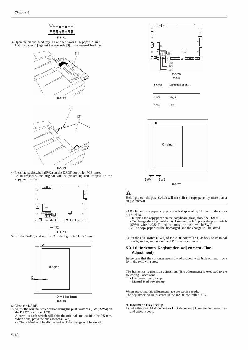
Chapter 5
5-18
F-5-713) Open the manual feed tray [1], and set A4 or LTR paper [2] in it.
But the paper [1] against the rear side [3] of the manual feed tray.
F-5-72
F-5-734) Press the push switch (SW2) on the DADF controller PCB once.
-> In response, the original will be picked up and stopped on thecopyboard cover.
F-5-745) Lift the DADF, and see that D in the figure is 11 +/- 1 mm.
F-5-756) Close the DADF.7) Adjust the original stop position using the push switches (SW3, SW4) on
the DADF controller PCB.A press on each switch will shift the original stop position by 0.5 mm.When done, press the push switch (SW2).-> The original will be discharged, and the change will be saved.
F-5-76T-5-8
F-5-77
Holding down the push switch will not shift the copy paper by more than asingle interval.
<EX> If the copy paper stop position is displaced by 12 mm on the copy-board glass,
- Keeping the copy paper on the copyboard glass, close the DADF.- To change the stop position by 1 mm to the left, press the push switch(SW4) twice (1/0.5=2), and then press the push switch (SW2).-> The copy paper will be discharged, and the change will be saved.
8) Put the DIP switch (SW1) of the ADF controller PCB back to its initialconfiguration, and mount the ADF controller cover.
5.3.1.6 Horizontal Registration Adjustment (Fine Adjustment)
0013-3802
In the case that the customer needs the adjustment with high accuracy, per-form the following step.
The horizontal registration adjustment (fine adjustment) is executed to thefollowing 2 occasions.
- Document tray pickup- Manual feed tray pickup
When executing this adjustment, use the service mode.The adjustment value is stored in the DADF controller PCB.
A. Document Tray Pickup1) Set either one A4 document or LTR document [1] on the document tray
and execute copy.
[1]
[2]
[3]
J1
J2
J5
J3 J6 J7 J8 J9 J10
J16 J15
J11
J14
IC8
J13
J12
J4CB1
SW1
DSP1SW4SW3SW2
D
Original
D 11 1mm
Switch Direction of shift
SW3 Right
SW4 Left
J1
J2
J5
J3 J6 J7 J8 J9 J10
J16 J15
J11
J14
IC8
J13
J12
J4CB1
SW1
DSP1SW4SW3SW2
Original
SW3SW4
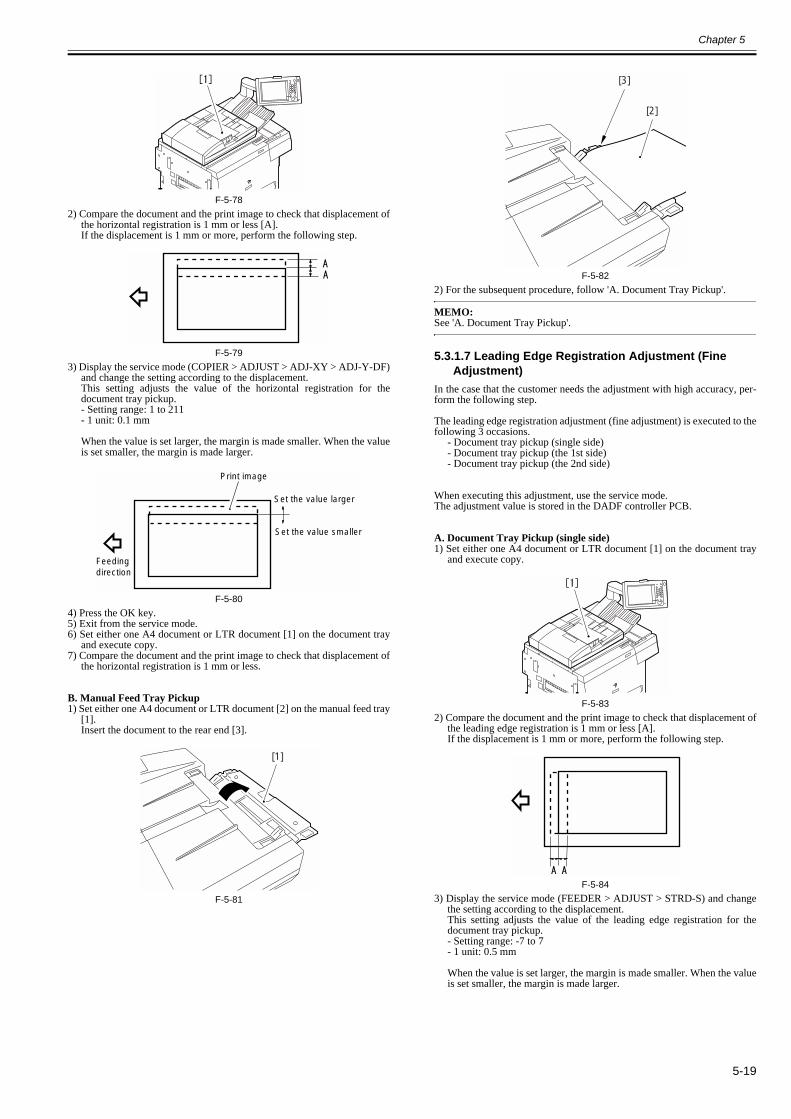
Chapter 5
5-19
F-5-782) Compare the document and the print image to check that displacement of
the horizontal registration is 1 mm or less [A].If the displacement is 1 mm or more, perform the following step.
F-5-793) Display the service mode (COPIER > ADJUST > ADJ-XY > ADJ-Y-DF)
and change the setting according to the displacement.This setting adjusts the value of the horizontal registration for thedocument tray pickup.- Setting range: 1 to 211- 1 unit: 0.1 mm
When the value is set larger, the margin is made smaller. When the valueis set smaller, the margin is made larger.
F-5-804) Press the OK key.5) Exit from the service mode.6) Set either one A4 document or LTR document [1] on the document tray
and execute copy.7) Compare the document and the print image to check that displacement of
the horizontal registration is 1 mm or less.
B. Manual Feed Tray Pickup1) Set either one A4 document or LTR document [2] on the manual feed tray
[1].Insert the document to the rear end [3].
F-5-81
F-5-822) For the subsequent procedure, follow 'A. Document Tray Pickup'.
MEMO:See 'A. Document Tray Pickup'.
5.3.1.7 Leading Edge Registration Adjustment (Fine Adjustment)
0013-3844
In the case that the customer needs the adjustment with high accuracy, per-form the following step.
The leading edge registration adjustment (fine adjustment) is executed to thefollowing 3 occasions.
- Document tray pickup (single side)- Document tray pickup (the 1st side)- Document tray pickup (the 2nd side)
When executing this adjustment, use the service mode.The adjustment value is stored in the DADF controller PCB.
A. Document Tray Pickup (single side)1) Set either one A4 document or LTR document [1] on the document tray
and execute copy.
F-5-832) Compare the document and the print image to check that displacement of
the leading edge registration is 1 mm or less [A].If the displacement is 1 mm or more, perform the following step.
F-5-843) Display the service mode (FEEDER > ADJUST > STRD-S) and change
the setting according to the displacement.This setting adjusts the value of the leading edge registration for thedocument tray pickup.- Setting range: -7 to 7- 1 unit: 0.5 mm
When the value is set larger, the margin is made smaller. When the valueis set smaller, the margin is made larger.
Feeding direction
Set the value larger
Set the value smaller
Print image
[1]
[2]
[3]

Chapter 5
5-20
F-5-854) Press the OK key.5) Exit from the service mode.6) Set either one A4 document or LTR document on the document tray and
execute copy.7) Compare the document and the print image to check that displacement of
the leading edge registration is 1 mm or less.
B. Document Tray Pickup (the 1st side)1) Set either one A4 document or LTR document [1] on the document tray
and execute double-sided copy.
F-5-862) For the subsequent procedure, follow 'A. Document Tray Pickup (single
side)'.For the service mode, use the following item:FEEDER > ADJSUT > DOCST
Measure the displacement of the 1st side (front side) of the print image.
C. Document Tray Pickup (the 2nd side)This procedure is the same as in the case of 'B. Document Tray Pickup (the1st side)'. For the service mode, use the following item:FEEDER > ADJSUT > DOCST-M
Measure the displacement of the 2nd side (back side) of the print image.
5.3.2 Adjustment at Time of Parts Replacement
5.3.2.1 Outline0013-3850
T-5-9
5.3.2.2 Replacing the EEPROM0013-3854
Perform the following when replacing the ADF controller PCB.1) Remove the EEPROM (IC8) from the faulty ADF controller PCB.
F-5-872) Mount the EEPROM removed in step 1) to the new ADF controller PCB.
MEMO:
Feeding direction
Set the value larger Set the value smaller
Print image
Major parts Work
ADF controller PCB 1) Replacement of the EEPROM
EEPROM (memory back-up) 2) Adjust the sensors and the delivery motor
Reversal sensor (S1)
Pre-registration roller paper sensor (S2)
Post-registration roller paper sensor (S3)
Separation paper sensor (S4)
Skew paper sensor (S5)
Original sensor (S6)
Original trailing edge sensor (S7)
Manual feed registration roller paper sensor (S9)
Delivery motor (M5)
J1
J2
J5
J3 J6 J7 J8 J9 J10
J16 J15
J11
J14
IC8
J13
J12
J4CB1
SW1
DSP1SW4SW3SW2

Chapter 5
5-21
The EEPROM on the new ADF controller PCB is not used yet.
3) Turn on the copier, and check to make sure that error code E420 is not in-dicated.4) If error code E420 is indicated, mount back the EERPOM once re-moved from the new ADF controller PCB.5) Perform the work under 1.2.3 "Adjusting the Sensors and the DeliveryMotor."
5.3.2.3 Adjusting the Sensors and the Delivery Motor0013-3868
Perform the adjustment if you have replaced any of the following parts:- EEPROM (memory backup)
- Reversal sensor (S1)- Pre-registration roller senor (S2)- Post-registration roller sensor (S3)- Separation paper sensor (S4)- Skew paper sensor (S5)- Original sensor (S6)- Original trailing edge sensor (S7)- Manual feed registration roller paper sensor (S9)- Delivery motor (M5)
MEMO:The delivery motor is adjusted by sending a reference signal to it, and thespeed of rotation at that time is measured by the delivery motor clock sensor(PI11).The result is used when generating the motor rotation speed control signal(EJMPWM*).
A. Steps to Take1) Open the DADF, and make a single A4 copy of a solid black original.
2) Remove the screw [1], and detach the ADF controller cover [2].
F-5-883) Set the DIP switch (SW1) on the ADF controller PCB as indicated.
F-5-894) Place the output obtained in step 1) in the original tray with the black side
facing down. Take care not to cover the original sensor (S6) when placingthe output.
F-5-905) Press the push switch (SW2) on the ADF controller PCB.
The LED will indicate the following in sequence, showing the result at theend: 1, 2, 3, 4, 5, 6, 7, 8, 9, A.
F-5-91T-5-10
6) At the end of the operation, press the push switch (SW2) on the ADF con-troller PCB once again.
If the Result is NGCheck the condition of each of the sensors (S1 through S9), and replace thesensor considered to be faulty.The condition of a sensor is indicated in the following three levels:
T-5-11
[1]
[2]
Black side down
Originalsensor (S6)
Original trailingedge paper sensor(S7)
Result DSP1 indication Description
OK
(O)
All sensors (S1 through S9) are normal).
NG
(F)
Any of the sensors (S1 through S9) is faulty.
Condition DSP1 indication Check or replace
Good
(Å?)
No
Alarm 1
(=)
No
Alarm 2
(-)
Yes
J1
J2
J5
J3 J6 J7 J8 J9 J10
J16 J15
J11
J14
IC8
J13
J12
J4CB1
SW1
DSP1SW4SW3SW2
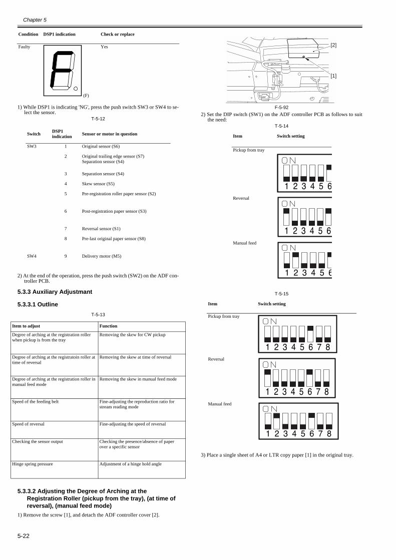
Chapter 5
5-22
1) While DSP1 is indicating 'NG', press the push switch SW3 or SW4 to se-lect the sensor.
T-5-12
2) At the end of the operation, press the push switch (SW2) on the ADF con-troller PCB.
5.3.3 Auxiliary Adjustmant
5.3.3.1 Outline0013-3884
T-5-13
5.3.3.2 Adjusting the Degree of Arching at the Registration Roller (pickup from the tray), (at time of reversal), (manual feed mode)
0013-3885
1) Remove the screw [1], and detach the ADF controller cover [2].
F-5-922) Set the DIP switch (SW1) on the ADF controller PCB as follows to suit
the need:T-5-14
T-5-15
3) Place a single sheet of A4 or LTR copy paper [1] in the original tray.
Faulty
(F)
Yes
Switch DSP1 indication Sensor or motor in question
SW3 1 Original sensor (S6)
2 Original trailing edge sensor (S7)Separation sensor (S4)
3 Separation sensor (S4)
4 Skew sensor (S5)
5 Pre-registration roller paper sensor (S2)
6 Post-registration paper sensor (S3)
7 Reversal sensor (S1)
8 Pre-last original paper sensor (S8)
SW4 9 Delivery motor (M5)
Item to adjust Function
Degree of arching at the registration roller when pickup is from the tray
Removing the skew for CW pickup
Degree of arching at the registratoin roller at time of reversal
Removing the skew at time of reversal
Degree of arching at the registration roller in manual feed mode
Removing the skew in manual feed mode
Speed of the feeding belt Fine-adjusting the reproduction ratio for stream reading mode
Speed of reversal Fine-adjusting the speed of reversal
Checking the sensor output Checking the presence/absence of paperover a specific sensor
Hinge spring pressure Adjustment of a hinge hold angle
Condition DSP1 indication Check or replace
Item Switch setting
Pickup from tray
Reversal
Manual feed
Item Switch setting
Pickup from tray
Reversal
Manual feed
[1]
[2]
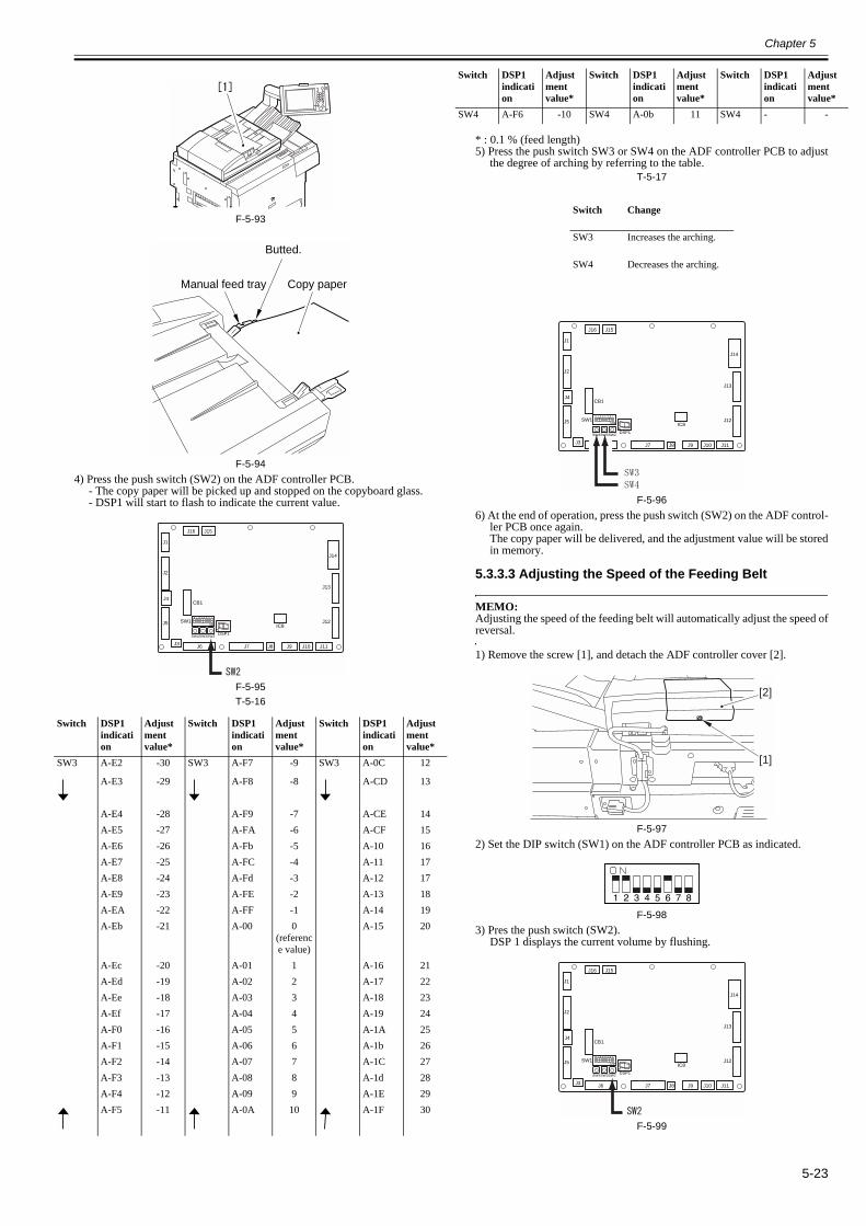
Chapter 5
5-23
F-5-93
F-5-944) Press the push switch (SW2) on the ADF controller PCB.
- The copy paper will be picked up and stopped on the copyboard glass.- DSP1 will start to flash to indicate the current value.
F-5-95T-5-16
* : 0.1 % (feed length)5) Press the push switch SW3 or SW4 on the ADF controller PCB to adjust
the degree of arching by referring to the table.T-5-17
F-5-966) At the end of operation, press the push switch (SW2) on the ADF control-
ler PCB once again.The copy paper will be delivered, and the adjustment value will be storedin memory.
5.3.3.3 Adjusting the Speed of the Feeding Belt0013-3891
MEMO:Adjusting the speed of the feeding belt will automatically adjust the speed ofreversal.
1) Remove the screw [1], and detach the ADF controller cover [2].
F-5-972) Set the DIP switch (SW1) on the ADF controller PCB as indicated.
F-5-983) Pres the push switch (SW2).
DSP 1 displays the current volume by flushing.
F-5-99
Switch DSP1 indication
Adjustment value*
Switch DSP1 indication
Adjustment value*
Switch DSP1 indication
Adjustment value*
SW3 A-E2 -30 SW3 A-F7 -9 SW3 A-0C 12
A-E3 -29 A-F8 -8 A-CD 13
A-E4 -28 A-F9 -7 A-CE 14A-E5 -27 A-FA -6 A-CF 15A-E6 -26 A-Fb -5 A-10 16A-E7 -25 A-FC -4 A-11 17A-E8 -24 A-Fd -3 A-12 17A-E9 -23 A-FE -2 A-13 18A-EA -22 A-FF -1 A-14 19A-Eb -21 A-00 0
(reference value)
A-15 20
A-Ec -20 A-01 1 A-16 21A-Ed -19 A-02 2 A-17 22A-Ee -18 A-03 3 A-18 23A-Ef -17 A-04 4 A-19 24A-F0 -16 A-05 5 A-1A 25A-F1 -15 A-06 6 A-1b 26A-F2 -14 A-07 7 A-1C 27A-F3 -13 A-08 8 A-1d 28A-F4 -12 A-09 9 A-1E 29A-F5 -11 A-0A 10 A-1F 30
Butted.
Manual feed tray Copy paper
J1
J2
J5
J3 J6 J7 J8 J9 J10
J16 J15
J11
J14
IC8
J13
J12
J4CB1
SW1
DSP1SW4SW3SW2
SW4 A-F6 -10 SW4 A-0b 11 SW4 - -
Switch Change
SW3 Increases the arching.
SW4 Decreases the arching.
Switch DSP1 indication
Adjustment value*
Switch DSP1 indication
Adjustment value*
Switch DSP1 indication
Adjustment value*
J1
J2
J5
J3 J6 J7 J8 J9 J10
J16 J15
J11
J14
IC8
J13
J12
J4CB1
SW1
DSP1SW4SW3SW2
[1]
[2]
J1
J2
J5
J3 J6 J7 J8 J9 J10
J16 J15
J11
J14
IC8
J13
J12
J4CB1
SW1
DSP1SW4SW3SW2
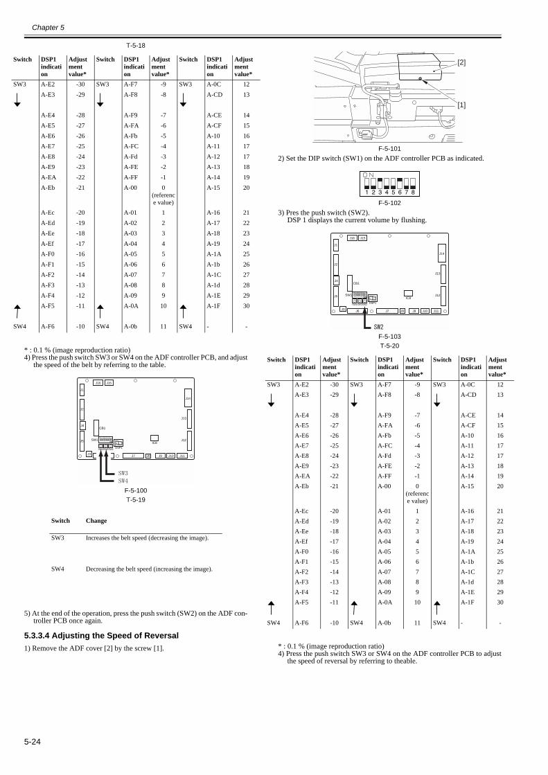
Chapter 5
5-24
T-5-18
* : 0.1 % (image reproduction ratio)4) Press the push switch SW3 or SW4 on the ADF controller PCB, and adjust
the speed of the belt by referring to the table.
F-5-100T-5-19
5) At the end of the operation, press the push switch (SW2) on the ADF con-troller PCB once again.
5.3.3.4 Adjusting the Speed of Reversal0013-3893
1) Remove the ADF cover [2] by the screw [1].
F-5-1012) Set the DIP switch (SW1) on the ADF controller PCB as indicated.
F-5-1023) Pres the push switch (SW2).
DSP 1 displays the current volume by flushing.
F-5-103T-5-20
* : 0.1 % (image reproduction ratio)4) Press the push switch SW3 or SW4 on the ADF controller PCB to adjust
the speed of reversal by referring to theable.
Switch DSP1 indication
Adjustment value*
Switch DSP1 indication
Adjustment value*
Switch DSP1 indication
Adjustment value*
SW3 A-E2 -30 SW3 A-F7 -9 SW3 A-0C 12A-E3 -29 A-F8 -8 A-CD 13
A-E4 -28 A-F9 -7 A-CE 14A-E5 -27 A-FA -6 A-CF 15A-E6 -26 A-Fb -5 A-10 16A-E7 -25 A-FC -4 A-11 17A-E8 -24 A-Fd -3 A-12 17A-E9 -23 A-FE -2 A-13 18A-EA -22 A-FF -1 A-14 19A-Eb -21 A-00 0
(reference value)
A-15 20
A-Ec -20 A-01 1 A-16 21A-Ed -19 A-02 2 A-17 22A-Ee -18 A-03 3 A-18 23A-Ef -17 A-04 4 A-19 24A-F0 -16 A-05 5 A-1A 25A-F1 -15 A-06 6 A-1b 26A-F2 -14 A-07 7 A-1C 27A-F3 -13 A-08 8 A-1d 28A-F4 -12 A-09 9 A-1E 29A-F5 -11 A-0A 10 A-1F 30
SW4 A-F6 -10 SW4 A-0b 11 SW4 - -
Switch Change
SW3 Increases the belt speed (decreasing the image).
SW4 Decreasing the belt speed (increasing the image).
J1
J2
J5
J3 J6 J7 J8 J9 J10
J16 J15
J11
J14
IC8
J13
J12
J4CB1
SW1
DSP1SW4SW3SW2
Switch DSP1 indication
Adjustment value*
Switch DSP1 indication
Adjustment value*
Switch DSP1 indication
Adjustment value*
SW3 A-E2 -30 SW3 A-F7 -9 SW3 A-0C 12A-E3 -29 A-F8 -8 A-CD 13
A-E4 -28 A-F9 -7 A-CE 14A-E5 -27 A-FA -6 A-CF 15A-E6 -26 A-Fb -5 A-10 16A-E7 -25 A-FC -4 A-11 17A-E8 -24 A-Fd -3 A-12 17A-E9 -23 A-FE -2 A-13 18A-EA -22 A-FF -1 A-14 19A-Eb -21 A-00 0
(reference value)
A-15 20
A-Ec -20 A-01 1 A-16 21A-Ed -19 A-02 2 A-17 22A-Ee -18 A-03 3 A-18 23A-Ef -17 A-04 4 A-19 24A-F0 -16 A-05 5 A-1A 25A-F1 -15 A-06 6 A-1b 26A-F2 -14 A-07 7 A-1C 27A-F3 -13 A-08 8 A-1d 28A-F4 -12 A-09 9 A-1E 29A-F5 -11 A-0A 10 A-1F 30
SW4 A-F6 -10 SW4 A-0b 11 SW4 - -
[1]
[2]
J1
J2
J5
J3 J6 J7 J8 J9 J10
J16 J15
J11
J14
IC8
J13
J12
J4CB1
SW1
DSP1SW4SW3SW2
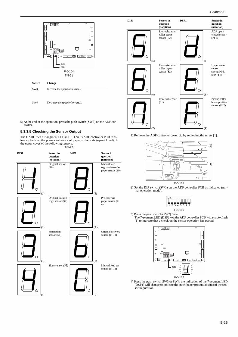
Chapter 5
5-25
F-5-104T-5-21
5) At the end of the operation, press the push switch (SW2) on the ADF con-troller.
5.3.3.5 Checking the Sensor Output0013-3896
The DADF uses a 7-segment LED (DSP1) on its ADF controller PCB to al-low a check on the presence/absence of paper or the state (open/closed) ofthe upper cover of the following sensors:
T-5-22
1) Remove the ADF controller cover [2] by removing the screw [1].
F-5-1052) Set the DIP switch (SW1) on the ADF controller PCB as indicated (nor-
mal operation mode).
F-5-1063) Press the push switch (SW2) once.
The 7-segment LED (DSP1) on the ADF controller PCB will start to flash[1] to indicate that a check on the sensor operation has started.
F-5-1074) Press the push switch SW3 or SW4; the indication of the 7-segment LED
(DSP1) will change to indicate the state (paper present/absent) of the sen-sor in question.
Switch Change
SW3 Increase the speed of reversal.
SW4 Decrease the speed of reversal.
DIS1 Sensor in question (notation)
DSP1 Sensor in question (notation)
(1)
Original sensor (S6)
(8)
Manual feed registration roller paper sensor (S9)
(2)
Original trailing edge sensor (S7)
(A)
Pre-reversal paper sensor (PI 4)
(3)
Separation sensor (S4)
(b)
Original delivery sensor (PI 13)
(4)
Skew sensor (S5)
(C)
Manual feed set sensor (PI 12)
J1
J2
J5
J3 J6 J7 J8 J9 J10
J16 J15
J11
J14
IC8
J13
J12
J4CB1
SW1
DSP1SW4SW3SW2
(5)
Pre-registration roller paper sensor (S2)
(d)
ADF open/closed sensor(PI 10)
(6)
Pre-registration roller paper sensor (S2)
(E)
Upper cover sensor(front; PI 6, rear;PI 3)
(7)
Reversal sensor (S1)
(F)
Pickup roller home position sensor (PI 7)
DIS1 Sensor in question (notation)
DSP1 Sensor in question (notation)
[1]
[2]
J1
J2
J5
J3 J6 J7 J8 J9 J10
J16 J15
J11
J14
IC8
J13
J12
J4CB1
SW1
DSP1SW4SW3SW2

Chapter 5
5-26
F-5-108T-5-23
5) To end the check, press the push switch (SW2) once.The LED2 indication will return to normal mode.
F-5-109
5.3.3.6 Hinge Spring Pressure Adjustment0013-3910
A. How to Check the Hinge1) Open the ADF widely.
F-5-1102) Close the ADF gradually and stop it just before the point where it closes
with its own weight (just before the hinge becomes unable to retain theADF).
F-5-1113) At this point, if the distance 'A' between the edge of the front cover and
the upper front cover is 20cm or more, perform the hinge spring pressureaadjustment described next.
F-5-112
B. How to Adjust the Pressure of Hinge Spring1. Hinge (left)
1) Unscrew a screw [1] and detach and pre-reversal solenoid mount [2].
F-5-1132) Rotate the spring pressure adjusting screw [A] of the hinge to the direction
of the arrow [B] (in a clockwise direction) using a hex wrench 18 timesby 60 degrees (Max. angle to be rotated per time) per time (Shorten thespring pressure adjusting screw [A] by 2 mm).
F-5-114
2. Hinge (right)1) Unscrew a screw [1] and detach the delivery motor clock sensor mount
[2].
DSP1 Presence/absence of paper
ON Present
Flashing Absent
J1
J2
J5
J3 J6 J7 J8 J9 J10
J16 J15
J11
J14
IC8
J13
J12
J4CB1
SW1
DSP1SW4SW3SW2
J1
J2
J5
J3 J6 J7 J8 J9 J10
J16 J15
J11
J14
IC8
J13
J12
J4CB1
SW1
DSP1SW4SW3SW2
A
[1] [2]
[1] [2]

Chapter 5
5-27
F-5-1152) Rotate the spring pressure adjusting screw [A] of the hinge to the direction
of the arrow [B] (in a clockwise direction) using a hex wrench 18 timesby 60 degrees (Max. angle to be rotated per time) per time (Shorten thespring pressure adjusting screw [A] by 2 mm).
F-5-116
5.3.4 Other
5.3.4.1 Outline0013-3914
T-5-24
5.3.4.2 Jam History0013-3919
1) Remove the screw [1], and detach the ADF controller cover [2].
F-5-1172) Set the DIP switch (SW1) on the ADF controller PCB as indicated.
F-5-1183) Press the push switch (SW2) on the ADF controller PCB.
DSP1 will indicate the latest jam code.
F-5-1194) Press the push switches SW3 and SW4 to change the DSP1 indication,
thereby checking the jam history.DSP1 will flash 5 times in sequence to indicate the nature of the jam.
F-5-120T-5-25
5) At the end of the check, press the push switch (SW2) on the ADF control-ler PCB once again.
5.3.4.3 Version of the Software0013-3921
1) Remove the screw [1], and detach the ADF controller cover [2].
Item Description
Jam history Indicates the most recent 3 jams.
Software version Indicates the version of the software.
Document width detection switch (SW301) check
A document width detection switch (SW301) check is carried out automatically.
Backup RAM clearance A backup RAM clear is performed.
[1][2]
[1][2]
Switch DSP1 Description
SW3 1-X1-X2-Y1-Y2 Previous (latest)
2-X1-X2-Y1-Y2 2nd most recent
SW4 3-X1-X2-Y1-Y2 3rd most recent
[1]
[2]
J1
J2
J5
J3 J6 J7 J8 J9 J10
J16 J15
J11
J14
IC8
J13
J12
J4CB1
SW1
DSP1SW4SW3SW2
J1
J2
J5
J3 J6 J7 J8 J9 J10
J16 J15
J11
J14
IC8
J13
J12
J4CB1
SW1
DSP1SW4SW3SW2

Chapter 5
5-28
F-5-1212) Set the DIP switch (SW1) on the ADF controller PCB as indicated.
F-5-1223) Press the push switch (SW2) on the ADF controller PCB.
DSP1 will flash 4 times to indicate the version of the software.
F-5-123EX:If for Version 3.01,
4) Press the push switch (SW2) on the ADF controller PCB to end the indi-cation.
5.3.4.4 Checking the Original Width0013-3923
1) Remove the screw [1], and detach the ADF controller cover [2].
F-5-1242) Set the DIP switch (SW1) on the ADF controller PCB as indicated.
F-5-1253) Press the push switch (SW2) on the ADF controller PCB.
DSP1 will go on or flash to indicate the width of the original each timethe position of the side guide is changed.
F-5-126T-5-26
Note: * The original width detecting switch (SW301) may be faulty.4) Press the push switch (SW2) on the ADF controller PCB to end the oper-
ation.
5.3.4.5 Resetting the Backup RAM0012-8904
1) Remove the ADF controller cover [2].- 1 screw [1]
F-5-1272) Set the DIP switch (SW1) on the ADF controller PCB as shown.
F-5-1283) Press the push switch (SW2) on the ADF controller PCB so that the ma-
chine will be in backup RAM reset mode.-> DSP1 goes off.
4) Press the push switch (SW3) 5 times in succession.-> DSP1 indicates ‘0’, and then the indication becomes reverse video.
[1]
[2]
J1
J2
J5
J3 J6 J7 J8 J9 J10
J16 J15
J11
J14
IC8
J13
J12
J4CB1
SW1
DSP1SW4SW3SW2
[1]
[2]
DSP1 indication Default size
0 ON A4
Flash Non-default
1 ON LTR
Flash Non-default
2 ON B4
Flash Non-default
3 ON LTR
Flash Non-default
4 ON A4
Flash Non-default
5 ON ERROR*
Flash ERROR
6 ON ERROR
Flash ERROR
7 ON ERROR*
Flash ERROR
J1
J2
J5
J3 J6 J7 J8 J9 J10
J16 J15
J11
J14
IC8
J13
J12
J4CB1
SW1
DSP1SW4SW3SW2
[1]
[2]

Chapter 5
5-29
F-5-129
J1
J2
J5
J3 J6 J7 J8 J9 J10
J16 J15
J11
J14
IC8
J13
J12
J4CB1
SW1
DSP1SW4SW3SW2

Chapter 5
5-30
5.4 Troubleshooting
5.4.1 Error Code
5.4.1.1 E402 display lamp0012-8906
Check the following in the indicated sequence: belt motor (M2), belt motor clock sensor (PI 1), belt motor driver PCB.A. Belt Motor (M2)1) Set the DIP switch (SW1) on the ADF controller PCB as shown.
F-5-1302) Press the push switch (SW2). (To stop, press the push switch once again.)
- If the belt motor rotates, go to B. "Belt Motor Clock Sensor (PI 1)."- If the belt motor does not rotate, go to step 3).
3) Replace the belt motor.
If no improvement is noted, go to B. "Belt Motor Clock Sensor (PI 1)."
B. Belt Motor Clock Sensor (PI 1)1) Bring in a tester, and set its test range to 10 VDC.2) Turn the belt motor by hand, and check the voltage between connectors "J12-2 (+)" and "J12-1 (-)" on the ADF controller PCB.
- If the voltage alternates between 0 and 5 V, go to C. "Belt Motor Driver PCB."- If the voltage does not alternate between 0 and 5 V, go to step 3).
3) Replace the belt motor clock sensor.
If no improvement is noted, go to C. "Belt Motor Driver PCB."
C. Belt Motor Driver PCB1) Check the cable connection between the belt motor driver PCB and the ADF controller PCB.
- If the cable is connected correctly, go to step 3).- If the cable is not connected correctly, go to step 2).
2) Connect the cable correctly.If no improvement is noted, go to step 3).
3) Replace the belt motor drive PCB.
If no improvement is noted, replace the ADF controller PCB.
5.4.1.2 E404 display lamp0012-8908
Check the following in the indicated sequence: delivery motor (M5), delivery motor clock sensor (PI 11).A. Delivery Motor (M5)1) Set the DIP switch (SW1) on the ADF controller PCB as shown.
F-5-1312) Press the push switch (SW2). (To stop, press the push switch once again.)
- If the delivery motor rotates, go to B. "Delivery Motor Clock Senor (PI 11)."- If the delivery motor does not rotate, go to step 3).
3) Replace the deliver motor.If you have replaced the delivery motor, be sure to perform the instructions under "Adjusting the Sensors and the Delivery Motor."
If no improvement is noted, go to B. "Delivery Motor Clock Sensor (PI 11)."
B. Delivery Motor Clock Sensor (PI 11)1) Bring in a tester, and set its test range to 10 VDC.2) Turn the delivery motor by hand, and check the voltage between connectors "J3-2 (+)" and "J3-1 (-)".
- If the voltage alternates between 0 and 5 V, go to step 3).- If the voltage does not alternate between 0 and 5 V, go to step 4).
3) Replace the ADF controller PCB.4) Replace the delivery motor clock sensor.
5.4.1.3 E405 display lamp0012-8909
Check Separation Motor (M4) and then Separation Motor Clock Sensor (PI 2).A. Separate Motor (M4)1) Set DIP switch (SW1) on ADF Controller PCB as shown in a figure.
F-5-1322) Press push switch (SW2). (Press push switch again when you want to stop it.)
- Separation motor is rotating: Go to "B. Separation Motor Clock Sensor (PI 2)."- Separation motor is not rotating: Go to the step 3.
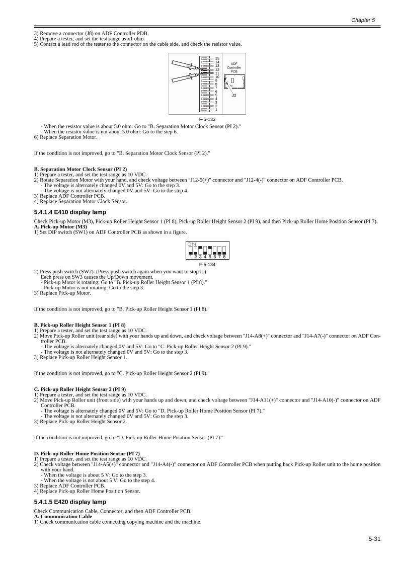
Chapter 5
5-31
3) Remove a connector (J8) on ADF Controller PDB.4) Prepare a tester, and set the test range as x1 ohm.5) Contact a lead rod of the tester to the connector on the cable side, and check the resistor value.
F-5-133- When the resistor value is about 5.0 ohm: Go to "B. Separation Motor Clock Sensor (PI 2)."- When the resistor value is not about 5.0 ohm: Go to the step 6.
6) Replace Separation Motor.
If the condition is not improved, go to "B. Separation Motor Clock Sensor (PI 2)."
B. Separation Motor Clock Sensor (PI 2)1) Prepare a tester, and set the test range as 10 VDC.2) Rotate Separation Motor with your hand, and check voltage between "J12-5(+)" connector and "J12-4(-)" connector on ADF Controller PCB.
- The voltage is alternately changed 0V and 5V: Go to the step 3.- The voltage is not alternately changed 0V and 5V: Go to the step 4.
3) Replace ADF Controller PCB.4) Replace Separation Motor Clock Sensor.
5.4.1.4 E410 display lamp0012-8911
Check Pick-up Motor (M3), Pick-up Roller Height Sensor 1 (PI 8), Pick-up Roller Height Sensor 2 (PI 9), and then Pick-up Roller Home Position Sensor (PI 7).A. Pick-up Motor (M3)1) Set DIP switch (SW1) on ADF Controller PCB as shown in a figure.
F-5-1342) Press push switch (SW2). (Press push switch again when you want to stop it.)
Each press on SW3 causes the Up/Down movement.- Pick-up Motor is rotating: Go to "B. Pick-up Roller Height Sensor 1 (PI 8)."- Pick-up Motor is not rotating: Go to the step 3.
3) Replace Pick-up Motor.
If the condition is not improved, go to "B. Pick-up Roller Height Sensor 1 (PI 8)."
B. Pick-up Roller Height Sensor 1 (PI 8)1) Prepare a tester, and set the test range as 10 VDC.2) Move Pick-up Roller unit (rear side) with your hands up and down, and check voltage between "J14-A8(+)" connector and "J14-A7(-)" connector on ADF Con-
troller PCB.- The voltage is alternately changed 0V and 5V: Go to "C. Pick-up Roller Height Sensor 2 (PI 9)."- The voltage is not alternately changed 0V and 5V: Go to the step 3.
3) Replace Pick-up Roller Height Sensor 1.
If the condition is not improved, go to "C. Pick-up Roller Height Sensor 2 (PI 9)."
C. Pick-up Roller Height Sensor 2 (PI 9)1) Prepare a tester, and set the test range as 10 VDC.2) Move Pick-up Roller unit (front side) with your hands up and down, and check voltage between "J14-A11(+)" connector and "J14-A10(-)" connector on ADF
Controller PCB.- The voltage is alternately changed 0V and 5V: Go to "D. Pick-up Roller Home Position Sensor (PI 7)."- The voltage is not alternately changed 0V and 5V: Go to the step 3.
3) Replace Pick-up Roller Height Sensor 2.
If the condition is not improved, go to "D. Pick-up Roller Home Position Sensor (PI 7)."
D. Pick-up Roller Home Position Sensor (PI 7)1) Prepare a tester, and set the test range as 10 VDC.2) Check voltage between "J14-A5(+)" connector and "J14-A4(-)" connector on ADF Controller PCB when putting back Pick-up Roller unit to the home position
with your hand.- When the voltage is about 5 V: Go to the step 3.- When the voltage is not about 5 V: Go to the step 4.
3) Replace ADF Controller PCB.4) Replace Pick-up Roller Home Position Sensor.
5.4.1.5 E420 display lamp0012-8912
Check Communication Cable, Connector, and then ADF Controller PCB.A. Communication Cable1) Check communication cable connecting copying machine and the machine.
151413121110987654321
J2
ADFController
PCB
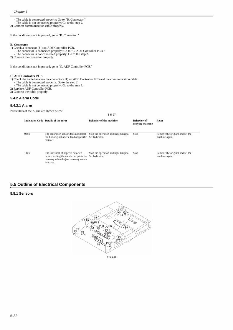
Chapter 5
5-32
- The cable is connected properly: Go to "B. Connector."- The cable is not connected properly: Go to the step 2.
2) Connect communication cable properly.
If the condition is not improved, go to "B. Connector."
B. Connector1) Check a connector (J1) on ADF Controller PCB.
- The connector is connected properly: Go to "C. ADF Controller PCB."- The connector is not connected properly: Go to the step 2.
2) Connect the connector properly.
If the condition is not improved, go to "C. ADF Controller PCB."
C. ADF Controller PCB1) Check the cable between the connector (J1) on ADF Controller PCB and the communication cable.
- The cable is connected properly: Go to the step 2.- The cable is not connected properly: Go to the step 3.
2) Replace ADF Controller PCB.3) Connect the cable properly.
5.4.2 Alarm Code
5.4.2.1 Alarm0012-8913
Particulars of the Alarm are shown below.T-5-27
5.5 Outline of Electrical Components
5.5.1 Sensors0013-3928
F-5-135
Indication Code Details of the error Behavior of the machine Behavior of copying machine
Reset
03xx The separation sensor does not detect the 1 st original after a feed of specific distance.
Stop the operation and light Original Set Indicator.
Stop Remove the origianl and set the machine again.
11xx The last sheet of paper is detected before feeding the number of prints for recovery when the jam recovery sensor is active.
Stop the operation and light Original Set Indicator.
Stop Remove the original and set the machine again.
PI 10
PI 11
PI 13
PI 12
PI 4
PI 1PI 3
PI 2
PI 7
PI 6PI 5
PI 9
PI 8
S1
S2S3
S5
S6
S6
S7
S4
S9
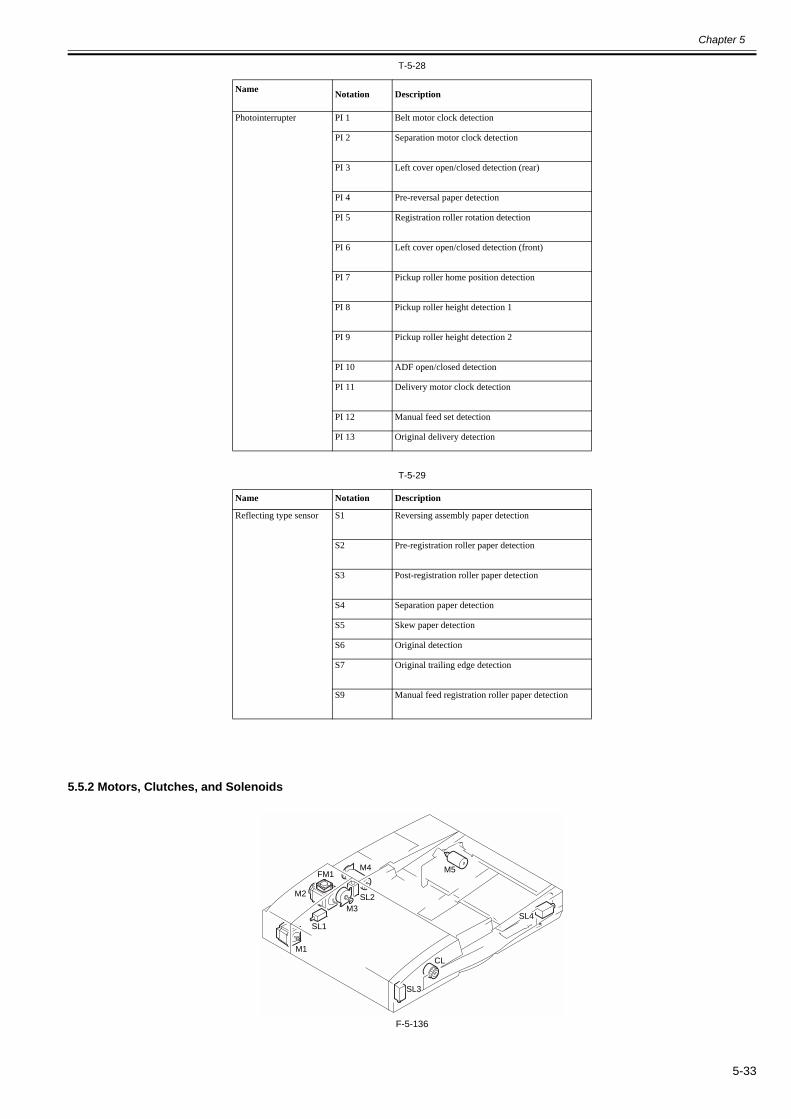
Chapter 5
5-33
T-5-28
T-5-29
5.5.2 Motors, Clutches, and Solenoids0013-3931
F-5-136
Name Notation Description
Photointerrupter PI 1 Belt motor clock detection
PI 2 Separation motor clock detection
PI 3 Left cover open/closed detection (rear)
PI 4 Pre-reversal paper detection
PI 5 Registration roller rotation detection
PI 6 Left cover open/closed detection (front)
PI 7 Pickup roller home position detection
PI 8 Pickup roller height detection 1
PI 9 Pickup roller height detection 2
PI 10 ADF open/closed detection
PI 11 Delivery motor clock detection
PI 12 Manual feed set detection
PI 13 Original delivery detection
Name Notation Description
Reflecting type sensor S1 Reversing assembly paper detection
S2 Pre-registration roller paper detection
S3 Post-registration roller paper detection
S4 Separation paper detection
S5 Skew paper detection
S6 Original detection
S7 Original trailing edge detection
S9 Manual feed registration roller paper detection
SL1SL4
SL2
SL3
M3
M1
M2
FM1 M5M4
CL

Chapter 5
5-34
T-5-30
5.5.3 PCBs0013-3932
F-5-137T-5-31
5.6 Variable Resistors (VR), Light-Emitting Diodes (LED), and Check Pins by PCB
5.6.1 Outline0013-3934
Of the LEDs and check pins found in the machine, those used in the field are discussed:
Do not touch any check pins that are not indicated in the table. They are for the factory, and require special tools and high precision.
5.6.2 ADF Controller PCB0013-3935
Some LEDs emit light when they are off because of leakage current. This is a normal condition, and must be kept in mind.
Arrangement of Components
Name Notation Description
Motor M1 Reversal motor
M2 Belt motor
M3 Pickup motor
M4 Separation motor
M5 Delivery motor
Clutch CL Separation clutch
Solenoid SL1 Reversing solenoid
SL2 Stopper plate solenoid
SL3 Pre-reversal solenoid
SL4 Delivery solenoid
Fan FM1 Belt motor cooling fan
Reference Name
1 ADF controller PCB
2 Reversal motor driver PCB
3 Belt motor driver PCB
4 Pickup tray PCB
5 Indication LED PCB
1
23
4
5

Chapter 5
5-35
F-5-138
5.6.3 DIP Switch Functions0013-3936
The DIP switch (SW1) on the ADF controller PCB provides the following functions according to how it is set:T-5-32
Setting Description
Normal Operation
Single-Sided Intermittent Feed
Press the push switch SW2 on the ADF controller PCB; thereafter, each press on the push switch SW2 will send the original intermittently.
Double-Sided Intermittent Feed
Press the push switch SW2 on the ADF controller PCB; thereafter, each press on the push switch SW2 will send the original intermittently.
Belt Motor (M2) Drive
Press the push switch SW2 on the ADF controller PCB to start it; another press will stop it.
The operation will be as follows, executed automatically:
CW (700 -> 520 -> 260 -> 30 mm/sec) ->
CCW: 700 -> 520 -> 260 -> 130 mm/sec).
Reversal Motor (M1) Drive
Press the push switch SW2 on the ADF controller PCB to start it; another press will stop it.
The operation will be as follows, executed automatically:
CW (700 -> 520 -> 260 -> 130 mm/sec) ->
CCW (700-> 520 -> 260 -> 130 mm/sec).
J1
J2
J5
J3 J6 J7 J8 J9 J10
J16 J15
J11
J14
IC8
J13
J12
J4CB1
SW1
DSP1SW4SW3SW2

Chapter 5
5-36
Delivery Motor (M5) Drive
Press the push switch SW2 on the ADF controller PCB to start it; another press will stop it.
While in operation, each press on the push switch SW3 changes the speed of motor rotation to 100mm/sec. (700 -> 100 mm/sec)
Pickup Motor (M3) Drive
Press the push switch (SW2) on the ADF controller PCB; press SW3 to move up or SW4 to move down. Another press on SW2 will stop it.
Solenoid/Clutch Drive
Press the push switch SW2 on the ADF controller PCB to execute the following in sequence; the operation will end automatically:
Stopper plate solenoid (SL2)
->
Delivery solenoid (SL4)
->
Pre-reversal solenoid (SL3)
->
Reversal solenoid (SL1)
->
Clutch (CL)
Separation Motor (M4), Clutch (CL) Drive
Press the push switch (SW2) on the ADF controller PCB to start it; another press will stop it.
While in operation, each press on the push switch SW3 changes the speed of motor rotation to 100mm/sec. (700 -> 100 mm/sec)
Manual Feed Operation
Place an original in the manual feed assembly, and press the push switch (SW2) on the ADF controller PCB so that the original will be picked up and stopped.
Tray Pickup Arch Adjustment
Press the push switch SW2 on the ADF controller PCB to start, and use the push switch SW3/SW4 to make adjustments. At the end, press the push switch SW2 to store the new setting.
Reversal Arch adjustment
Press the push switch SW2 on the ADF controller PCB to start, and use the push switch SW3/SW4 to make adjustments. At the end, press the push switch SW2 to store the new setting.
Manual Feed Arch Adjustment
Press the push switch SW2 on the ADF controller PCB to start, and use the push switch SW3/SW4 to make adjustments. At the end, press the push switch SW2 to store the new setting.
Setting Description
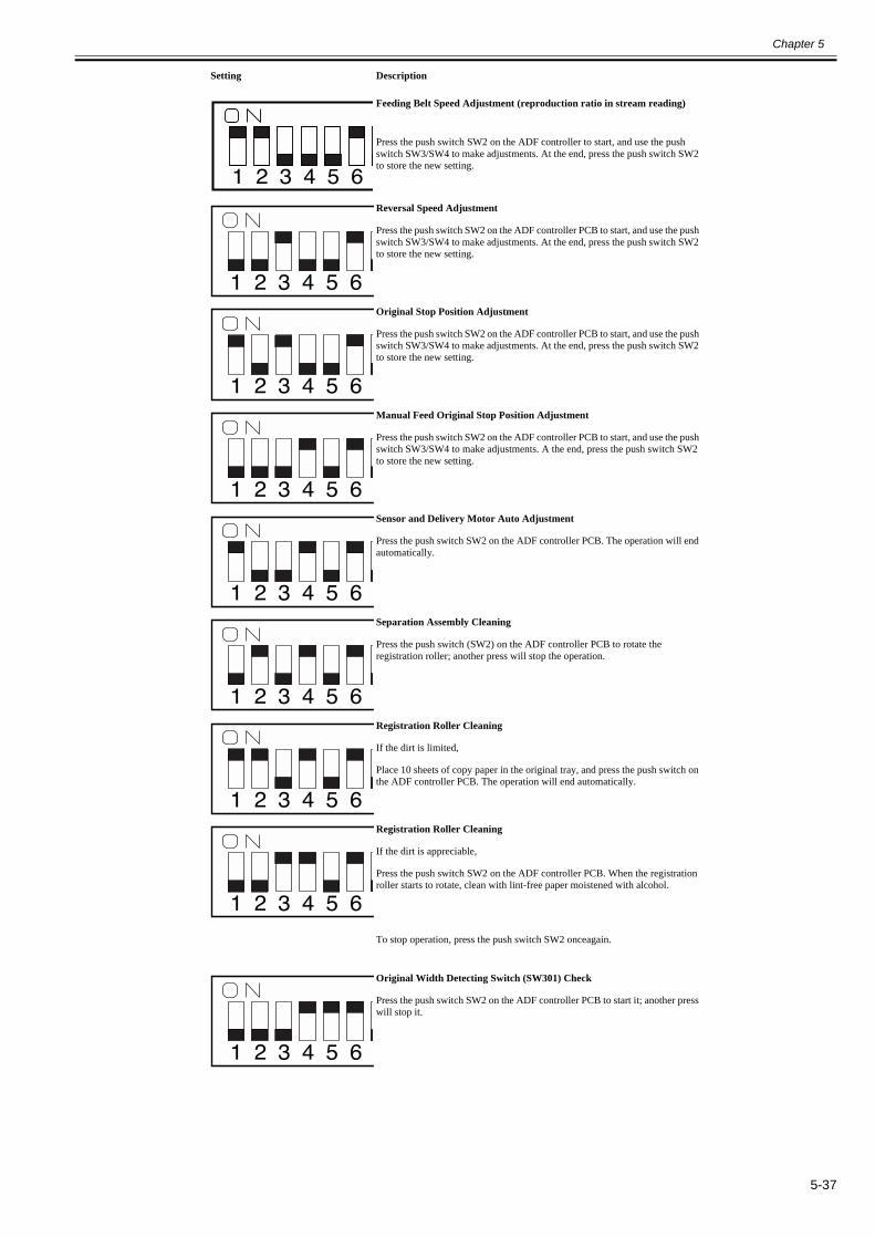
Chapter 5
5-37
Feeding Belt Speed Adjustment (reproduction ratio in stream reading)
Press the push switch SW2 on the ADF controller to start, and use the push switch SW3/SW4 to make adjustments. At the end, press the push switch SW2 to store the new setting.
Reversal Speed Adjustment
Press the push switch SW2 on the ADF controller PCB to start, and use the push switch SW3/SW4 to make adjustments. At the end, press the push switch SW2 to store the new setting.
Original Stop Position Adjustment
Press the push switch SW2 on the ADF controller PCB to start, and use the push switch SW3/SW4 to make adjustments. At the end, press the push switch SW2 to store the new setting.
Manual Feed Original Stop Position Adjustment
Press the push switch SW2 on the ADF controller PCB to start, and use the push switch SW3/SW4 to make adjustments. A the end, press the push switch SW2 to store the new setting.
Sensor and Delivery Motor Auto Adjustment
Press the push switch SW2 on the ADF controller PCB. The operation will end automatically.
Separation Assembly Cleaning
Press the push switch (SW2) on the ADF controller PCB to rotate the registration roller; another press will stop the operation.
Registration Roller Cleaning
If the dirt is limited,
Place 10 sheets of copy paper in the original tray, and press the push switch on the ADF controller PCB. The operation will end automatically.
Registration Roller Cleaning
If the dirt is appreciable,
Press the push switch SW2 on the ADF controller PCB. When the registration roller starts to rotate, clean with lint-free paper moistened with alcohol.
To stop operation, press the push switch SW2 onceagain.
Original Width Detecting Switch (SW301) Check
Press the push switch SW2 on the ADF controller PCB to start it; another press will stop it.
Setting Description
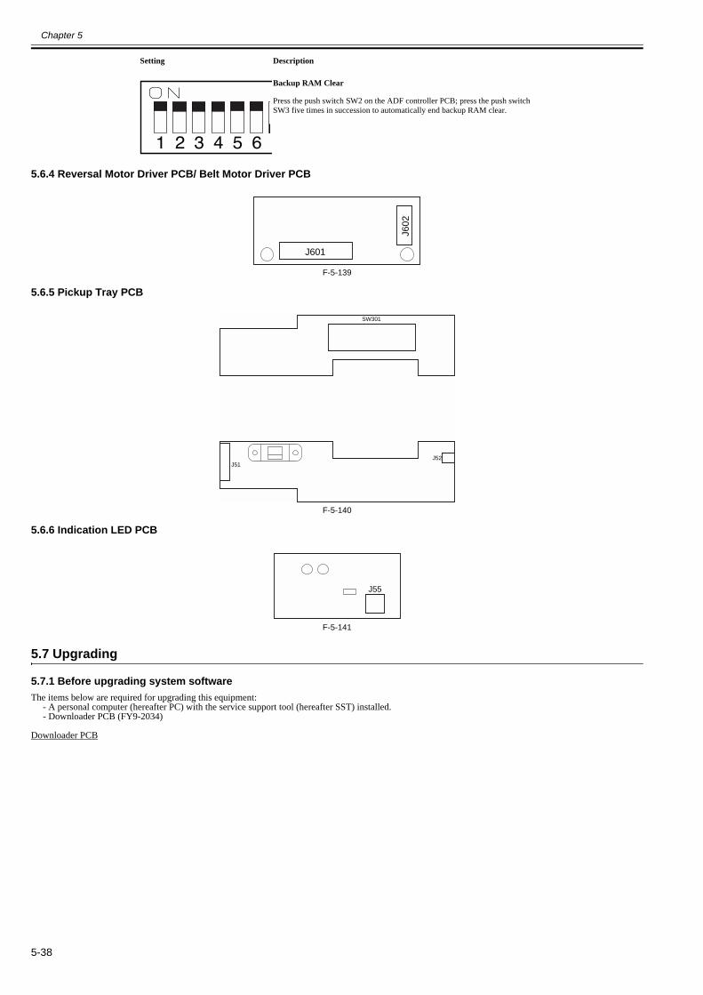
Chapter 5
5-38
5.6.4 Reversal Motor Driver PCB/ Belt Motor Driver PCB0013-3945
F-5-139
5.6.5 Pickup Tray PCB0013-3947
F-5-140
5.6.6 Indication LED PCB0013-3949
F-5-141
5.7 Upgrading
5.7.1 Before upgrading system software0017-5589
The items below are required for upgrading this equipment:- A personal computer (hereafter PC) with the service support tool (hereafter SST) installed.- Downloader PCB (FY9-2034)
Downloader PCB
Backup RAM Clear
Press the push switch SW2 on the ADF controller PCB; press the push switch SW3 five times in succession to automatically end backup RAM clear.
Setting Description
J602
J601
J51J52
SW301
J55

Chapter 5
5-39
F-5-142T-5-33
No. Name Function[1] Start/Stop key A key to be pressed when you start or stop download[2] Laod LED Illuminated when download is ready.[3] CPU Type LED Illuminated when the connection to the equipment (ADF) is recognized.[4] Power LED Illuminated when the power is supplied from this equipment (ADF) to the downloader PCB.[5] RS-232C cable
(straight thru cable, 9-pin)Cable used to connect the downloader PCB and the PC.Connect the cable end with the ferrite core to the PC.
[6] Cable A (9-pin; about 70 cm long) Cable used to connect the downloader PCB and the other equipments.[7] Cable B (7-pin); about 50 cm long) Cable used to connect the downloader PCB and this equipment (ADF).[8] RS-232C connector Connection interface for RS-232C cable
MEMO:Please refer to the chapter of "Version Upgrade" in Service Manual for the machine on how to register the firmware to the supported SST/PC and SST.
[1] [2] [3] [4] [6][7][5] [8]
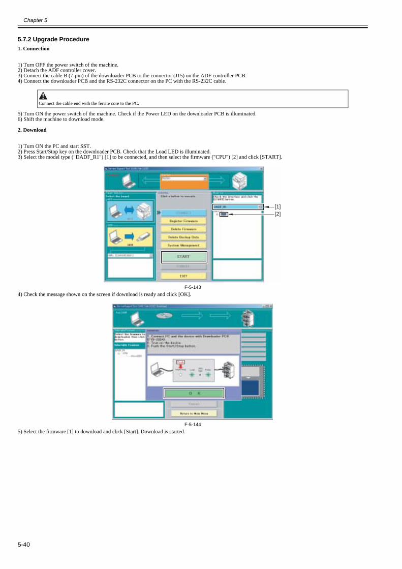
Chapter 5
5-40
5.7.2 Upgrade Procedure0017-5588
1. Connection
1) Turn OFF the power switch of the machine.2) Detach the ADF controller cover.3) Connect the cable B (7-pin) of the downloader PCB to the connector (J15) on the ADF controller PCB.4) Connect the downloader PCB and the RS-232C connector on the PC with the RS-232C cable.
5) Turn ON the power switch of the machine. Check if the Power LED on the downloader PCB is illuminated.6) Shift the machine to download mode.
2. Download
1) Turn ON the PC and start SST.2) Press Start/Stop key on the downloader PCB. Check that the Load LED is illuminated.3) Select the model type ("DADF_R1") [1] to be connected, and then select the firmware ("CPU") [2] and click [START].
F-5-1434) Check the message shown on the screen if download is ready and click [OK].
F-5-1445) Select the firmware [1] to download and click [Start]. Download is started.
Connect the cable end with the ferrite core to the PC.
[1][2]
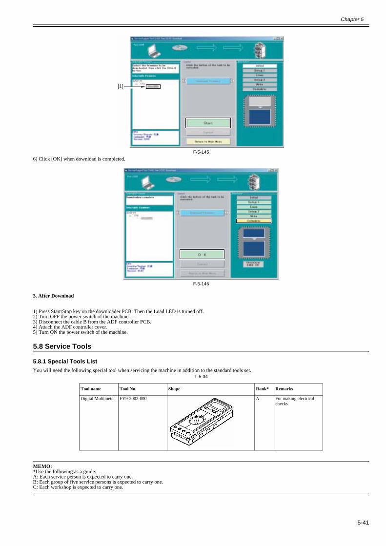
Chapter 5
5-41
F-5-1456) Click [OK] when download is completed.
F-5-146
3. After Download
1) Press Start/Stop key on the downloader PCB. Then the Load LED is turned off.2) Turn OFF the power switch of the machine.3) Disconnect the cable B from the ADF controller PCB.4) Attach the ADF controller cover.5) Turn ON the power switch of the machine.
5.8 Service Tools
5.8.1 Special Tools List0013-3950
You will need the following special tool when servicing the machine in addition to the standard tools set.T-5-34
MEMO:*Use the following as a guide:A: Each service person is expected to carry one.B: Each group of five service persons is expected to carry one.C: Each workshop is expected to carry one.
Tool name Tool No. Shape Rank* Remarks
Digital Multimeter FY9-2002-000 A For making electrical checks
[1]

Chapter 5
5-42
5.8.2 Solvents and Oils List0013-3951
F-5-147
No. Name Uses Composition Remarks
1 Alcohol Cleaning; e.g., glass, plastic, rubber (external covers).
Fluorine-family hydrogen carbon, alcohol, surface activating agent
• Do not bring near fire.• Procure locally.• IPA (isopropyl alcohol)
2 Lubricant Driving parts, friction parts
Silicone oil CK-0551 (20 g)

Chapter 6 Error Code


Contents
Contents
6.1 Service Error Code.........................................................................................................................................................6-16.1.1 E402 ............................................................................................................................................................................................. 6-16.1.2 E404 ............................................................................................................................................................................................. 6-16.1.3 E405 ............................................................................................................................................................................................. 6-16.1.4 E410 ............................................................................................................................................................................................. 6-16.1.5 E420 ............................................................................................................................................................................................. 6-1
6.2 Jam Codes ......................................................................................................................................................................6-16.2.1 List of Jam Code .......................................................................................................................................................................... 6-1
6.3 Alam Code .....................................................................................................................................................................6-46.3.1 List of Alarm Code ...................................................................................................................................................................... 6-4

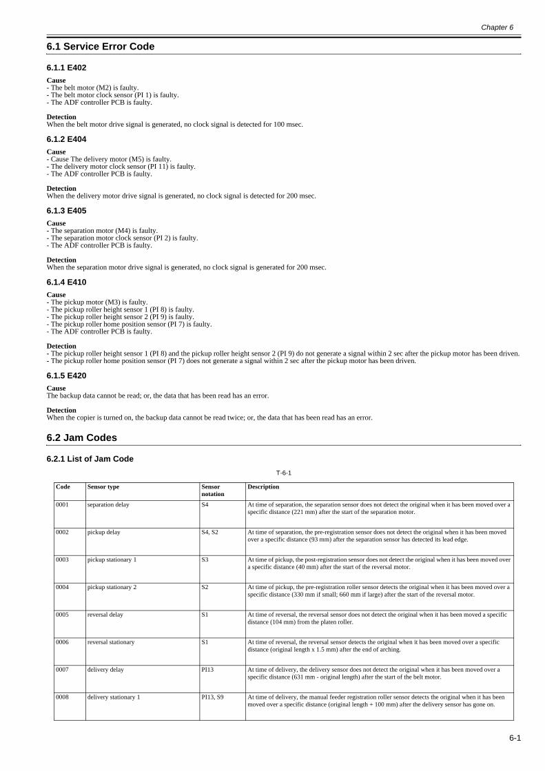
Chapter 6
6-1
6.1 Service Error Code
6.1.1 E4020013-3982
Cause- The belt motor (M2) is faulty.- The belt motor clock sensor (PI 1) is faulty.- The ADF controller PCB is faulty.
DetectionWhen the belt motor drive signal is generated, no clock signal is detected for 100 msec.
6.1.2 E4040013-3983
Cause- Cause The delivery motor (M5) is faulty.- The delivery motor clock sensor (PI 11) is faulty.- The ADF controller PCB is faulty.
DetectionWhen the delivery motor drive signal is generated, no clock signal is detected for 200 msec.
6.1.3 E4050013-3984
Cause- The separation motor (M4) is faulty.- The separation motor clock sensor (PI 2) is faulty.- The ADF controller PCB is faulty.
DetectionWhen the separation motor drive signal is generated, no clock signal is generated for 200 msec.
6.1.4 E4100013-3985
Cause- The pickup motor (M3) is faulty.- The pickup roller height sensor 1 (PI 8) is faulty.- The pickup roller height sensor 2 (PI 9) is faulty.- The pickup roller home position sensor (PI 7) is faulty.- The ADF controller PCB is faulty.
Detection- The pickup roller height sensor 1 (PI 8) and the pickup roller height sensor 2 (PI 9) do not generate a signal within 2 sec after the pickup motor has been driven.- The pickup roller home position sensor (PI 7) does not generate a signal within 2 sec after the pickup motor has been driven.
6.1.5 E4200013-3986
CauseThe backup data cannot be read; or, the data that has been read has an error.
DetectionWhen the copier is turned on, the backup data cannot be read twice; or, the data that has been read has an error.
6.2 Jam Codes
6.2.1 List of Jam Code0013-4228
T-6-1
Code Sensor type Sensor notation
Description
0001 separation delay S4 At time of separation, the separation sensor does not detect the original when it has been moved over a specific distance (221 mm) after the start of the separation motor.
0002 pickup delay S4, S2 At time of separation, the pre-registration sensor does not detect the original when it has been moved over a specific distance (93 mm) after the separation sensor has detected its lead edge.
0003 pickup stationary 1 S3 At time of pickup, the post-registration sensor does not detect the original when it has been moved over a specific distance (40 mm) after the start of the reversal motor.
0004 pickup stationary 2 S2 At time of pickup, the pre-registration roller sensor detects the original when it has been moved over a specific distance (330 mm if small; 660 mm if large) after the start of the reversal motor.
0005 reversal delay S1 At time of reversal, the reversal sensor does not detect the original when it has been moved a specific distance (104 mm) from the platen roller.
0006 reversal stationary S1 At time of reversal, the reversal sensor detects the original when it has been moved over a specific distance (original length x 1.5 mm) after the end of arching.
0007 delivery delay PI13 At time of delivery, the delivery sensor does not detect the original when it has been moved over a specific distance (631 mm - original length) after the start of the belt motor.
0008 delivery stationary 1 PI13, S9 At time of delivery, the manual feeder registration roller sensor detects the original when it has been moved over a specific distance (original length + 100 mm) after the delivery sensor has gone on.
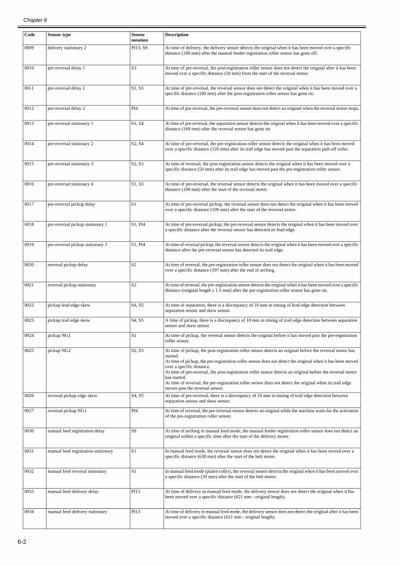
Chapter 6
6-2
0009 delivery stationary 2 PI13, S9 At time of delivery, the delivery sensor detects the original when it has been moved over a specific distance (100 mm) after the manual feeder registration roller sensor has gone off.
0010 pre-reversal delay 1 S3 At time of pre-reversal, the post-registration roller sensor does not detect the original after it has been moved over a specific distance (50 mm) from the start of the reversal motor.
0011 pre-reversal delay 2 S1, S3 At time of pre-reversal, the reversal sensor does not detect the original when it has been moved over a specific distance (100 mm) after the post-registration roller sensor has gone on.
0012 pre-reversal delay 2 PI4 At time of pre-reversal, the pre-reversal sensor does not detect an original when the reversal motor stops.
0013 pre-reversal stationary 1 S1, S4 At time of pre-reversal, the separation sensor detects the original when it has been moved over a specific distance (169 mm) after the reversal sensor has gone on.
0014 pre-reversal stationary 2 S2, S4 At time of pre-reversal, the pre-registration roller sensor detects the original when it has been moved over a specific distance (120 mm) after its trail edge has moved past the separation pull-off roller.
0015 pre-reversal stationary 3 S2, S3 At time of reversal, the post-registration sensor detects the original when it has been moved over a specific distance (50 mm) after its trail edge has moved past the pre-registration roller sensor.
0016 pre-reversal stationary 4 S1, S3 At time of pre-reversal, the reversal sensor detects the original when it has been moved over a specific distance (100 mm) after the start of the reversal motor.
0017 pre-reversal pickup delay S1 At time of pre-reversal pickup, the reversal sensor does not detect the original when it has been moved over a specific distance (100 mm) after the start of the reversal motor.
0018 pre-reversal pickup stationary 1 S1, PI4 At time of pre-reversal pickup, the pre-reversal sensor detects the original when it has been moved over a specific distance after the reversal sensor has detected its lead edge.
0019 pre-reversal pickup stationary 2 S1, PI4 At time of reversal pickup, the reversal sensor detects the original when it has been moved over a specific distance after the pre-reversal sensor has detected its trail edge.
0020 reversal pickup delay S2 At time of reversal, the pre-registration roller sensor does not detect the original when it has been moved over a specific distance (197 mm) after the end of arching.
0021 reversal pickup stationary S2 At time of reversal, the pre-registration sensor detects the original when it has been moved over a specific distance (original length x 1.5 mm) after the pre-registration roller sensor has gone on.
0022 pickup lead edge skew S4, S5 At time of separation, there is a discrepancy of 10 mm in timing of lead edge detection between separation sensor and skew sensor.
0023 pickup trail edge skew S4, S5 A time of pickup, there is a discrepancy of 10 mm in timing of trail edge detection between separation sensor and skew sensor.
0024 pickup NG1 S1 At time of pickup, the reversal sensor detects the original before it has moved past the pre-registration roller sensor.
0025 pickup NG2 S2, S3 At time of pickup, the post-registration roller sensor detects an original before the reversal motor has started.At time of pickup, the pre-registration roller sensor does not detect the original when it has been moved over a specific distance.At time of pre-reversal, the post-registration roller sensor detects an original before the reversal motor has started.At time of reversal, the pre-registration roller sensor does not detect the original when its trail edge moves past the reversal sensor.
0026 reversal pickup edge skew S4, S5 At time of pre-reversal, there is a discrepancy of 10 mm in timing of trail edge detection between separation sensor and skew sensor.
0027 reversal pickup NG1 PI4 At time of reversal, the pre-reversal sensor detects an original while the machine waits for the activation of the pre-registration roller sensor.
0030 manual feed registration delay S9 At time of arching in manual feed mode, the manual feeder registration roller sensor does not detect an original within a specific time after the start of the delivery motor.
0031 manual feed registration stationary S1 In manual feed mode, the reversal sensor does not detect the original when it has been moved over a specific distance (638 mm) after the start of the belt motor.
0032 manual feed reversal stationary S1 In manual feed mode (platen roller), the reversal sensor detects the original when it has been moved over a specific distance (50 mm) after the start of the belt motor.
0033 manual feed delivery delay PI13 At time of delivery in manual feed mode, the delivery sensor does not detect the original when it has been moved over a specific distance (621 mm - original length).
0034 manual feed delivery stationary PI13 At time of delivery in manual feed mode, the delivery sensor does not detect the original after it has been moved over a specific distance (621 mm - original length).
Code Sensor type Sensor notation
Description

Chapter 6
6-3
0043 1st sheet pickup stationary 1 S3 A pickup stationary 1 condition (0003) has occurred on the 1st sheet.
0044 1st sheet reversal delay S2 A pickup stationary 2 condition (0004) has occurred on the 1st sheet.
0045 1st sheet registration delay S1 A reversal delay condition (0005) has occurred on the 1st sheet.
0046 1st sheet reversal stationary S1 A reversal stationary condition (0006) has occurred on the 1st sheet.
0047 1st sheet delivery delay PI13 A delivery delay condition (0007) has occurred on the 1st sheet.
0048 1st sheet delivery stationary 1 PI13, S9 A delivery stationary condition (0008) has occurred on the 1st sheet.
0049 1st sheet delivery stationary 2 PI13, S9 A delivery stationary condition (0009) has occurred on the 1st sheet.
0050 1st sheet pre-reversal delay 1 S3 A pre-reversal delay 1 condition (0010) has occurred on the 1st sheet.
0051 1st sheet pre-reversal delay 2 S1, S3 A pre-reversal delay 1 condition (0011) has occurred on the 1st sheet.
0052 1st sheet pre-reversal delay 3 PI4 A pre-reversal delay 3 condition (0012) has occurred on the 1st sheet.
0053 1st sheet pre-reversal stationary 1 S1, S4 A pre-reversal delay 1 condition (0013) has occurred on the 1st sheet.
0054 1st sheet pre-reversal stationary 2 S2, S4 A pre-reversal stationary 2 condition (0014) has occurred on the 1st sheet.
0055 1st sheet pre-reversal stationary 3 S2, S3 A pre-reversal stationary 3 condition (0015) has occurred on the 1st sheet.
0056 1st sheet pre-reversal stationary 4 S1, S3 A pre-reversal stationary 4 condition (0016) has occurred on the 1st sheet.
0057 1st sheet pre-reversal pickup delay S1 A pre-reversal pickup delay condition (0017) has occurred on the 1st sheet.
0058 1st sheet pre-reversal pickup stationary 1 S1, PI4 A pre-reversal pickup stationary 1 condition (0018) has occurred on the 1st sheet.
0059 1st sheet pre-reversal stationary 2 S1, PI4 A pre-reversal pickup stationary 2 condition (0019) has occurred on the 1st sheet.
0060 1st sheet reversal pickup delay S2 A reversal pickup delay condition (0020) has occurred on the 1st sheet.
0061 1st sheet reversal pickup stationary S2 A reversal pickup stationary condition (0021) has occurred on the 1st sheet.
0062 1st sheet pickup lead edge skew S4, S5 A pickup lead edge skew condition (0022) has occurred on the 1st sheet.
0063 1st sheet pickup trail edge skew S4, S5 A pickup trail edge skew condition (0023) has occurred on the 1st sheet.
0064 1st sheet pickup NG1 S1 A pickup NG1 condition (0024) has occurred on the 1st sheet.
0065 1st sheet pickup NG2 S2, S3 A pickup NG2 condition (0025) has occurred on the 1st sheet.
0066 1st sheet reversal pickup trail edge skew S4, S5 A reversal pickup trail edge skew condition (0026) has occurred on the 1st sheet.
0067 1st sheet reversal pickup NG1 PI4 A reversal pickup NG1 condition (0027) has occurred on the 1st sheet.
0071 timing fault 1 - A software control mechanism has failed.
0072 timing fault 2 - At time of fixed reading, the delivery of the preceding original is not over when an original has been moved and stopped on the right side of the platen roller.
0073 illegal size S3 In LDR stream reading, the post-registration roller sensor detects the original when it has been moved over a specific distance (30 mm) from standby position.
0074 manual feeder original size fault S1, S9 In manual feed mode, the reversal sensor detects an original while the manual feeder registration roller sensor detects another original.
0075 image lead edge fault S7 In stream reading, no change of read position has taken place despite a request for a change of reading position.
0076 1st sheet image lead edge position fault S7 An image lead edge fault condition (0075) has occurred on the 1st sheet.
0077 belt speed setting fault PI1 The speed setting of the belt motor is the minimum speed (100 mm/sec) or lower or is the maximum speed (700 mm/sec) or higher.
0078 belt speed switchover fault PI1 At time of a belt motor speed switchover, the belt motor is not operating at a specific speed.
0079 belt status fault PI1 At time of a switchover of the belt motor state (acceleration, constant, deceleration), the motor is not in any of the 3 states.
Code Sensor type Sensor notation
Description

Chapter 6
6-4
6.3 Alam Code
6.3.1 List of Alarm Code0013-4229
T-6-2
0080 image lead edge output timing fault
S2, S3, SW301 At time of stream reading, the image lead edge signal is generated during acceleration over the distance from standby position to image lead edge position.
0081 reversal speed setting fault PI5 The speed setting of the reversal motor is the minimum speed (100 mm/sec) or lower or is the maximum speed (700 mm/sec) or higher.
0082 reversal speed switchover fault PI5 At time of a reversal motor speed switchover, the motor is not operating at a specific speed.
0083 reversal status fault PI5 At time of a switchover of the motor state (acceleration, constant, deceleration), the motor is not in any of the 3 settings.
0084 last original error PI1 While the last original is being discharged from the platen roller or is being moved, a belt motor error has occurred.
0085 error PI1, PI2, PI11 A motor error other than an IPC communication/pickup error has occurred. (less than 3 occurrences)
0090 ADF open PI10 An ADF open condition has been detected.
0091 user DF open PI10 An ADF open condition has been detected while the machine is in operation.
0092 cover open PI3, PI6 A cover open condition (front or rear) has been detected.
0093 user cover open PI3, PI6 While the machine is operating, a sensor in the paper path has detected an original.
0094 initial stationary PI4, PI12, PI13, S1, S2, S3, S4, S5, S9
At the start of operation, the presence of an original has been detected by a senser in the paper path.
0095 cycle NG S6 While no sensor is on, the pickup signal is received for a specific time (2 sec).
0096 residual original S1 Before the start of a left pickup job, the reversal sensor has detected an original while the belt motor is being driven for a specific time.
0097 manual feeder residual original S1, S9 At time of manual feed pickup, the reversal sensor detects an original while the manual feeder registration roller sensor also detects an original.
0098 power-down - While the machine is operating, a drop has occurred in the voltage of the power supplied by the host machine.
Code Name Description
03 separation fault a jam caused by the 1st original not reaching the post-separation sensor a jam caused by the 1st original not reaching the registration sensor
11 decrease in number of originalsafter jam recovery
a condition caused by a decrease in the number of originals in the tray before delivery of as many as [originals to be recovered - 1] have been delivered at time of jam recovery
21 mode fault selection of mode not permitting execution
Code Sensor type Sensor notation
Description

Feb 21 2008