
D400 Manual - DuoGen
22
tle Here Wind Generator D400 Serial Number:_______________ Voltage:_____________________ USER’S MANUAL
Transcript of D400 Manual - DuoGen

tle Here
WindGenerator
D400
Serial Number:_______________
Voltage:_____________________
USER’S MANUAL

1
Safety Issues
� When installing the D400, exercise due care at all times. The turbine weighs 17.2kilograms and is awkward in shape. It is best to plan the installation carefully inadvance and enlist some help when erecting the machine in order to avoid accidents.
� Complete as much of the installation procedure as possible at ground level.
� Choose a calm, dry day for your installation if possible.
� D400 blades are quite sharp, particularly on their trailing edges. Handle with care.
� D400 is robustly engineered, but contains high-energy ferrite magnets that can be dam-aged if the machine is dropped or handled heavily.
� When running, particularly if disconnected from the batteries, D400 is capable ofproducing high voltages. Caution must be exercised at all times to avoid electric shocks.
� Always observe correct polarity when connecting D400 to an electrical circuit. Reversepolarity connection will result in damage to the wind generator.
� The D400 must be appropriately fused at all times.
� Never approach the path of the blades when the machine is operating as severepersonal injury could result.
� Always stop the machine and secure the blades beforeattempting maintenance.
� Ensure that all batteries are disconnected when undertaking maintenance.
PLEASE NOTE:
The D400 is designed to be permanently connected to asuitable electrical load such as a battery bank, dumpregulator or inverter.
It should never be allowed to run unloaded,ie. open-circuit, for more than a few minutes.
In an open-circuit condition, the D400 will overspeed, andvery high voltages can be produced.
There is also a risk of damage to the machine’s rectifiers.

2
Thank you for purchasing the D400 Wind Generator,designed and manufactured by Eclectic Energy Limited.
The D400 is one of the most efficient, powerful and well-engineeredturbines currently available. Please read the entire manual
thoroughly prior to installation to ensure your personal safety andthe optimum performance of the equipment.
If you have any questions or uncertainties, having read the manual,please contact your authorised dealer, or Eclectic
Energy Ltd, for further clarification.
ContentsSafety issues 1
Introduction 2
Features of the D400 3
Dimensions 4
Output 4
Checklist (parts, tools etc) 5
Principles of wind energy 5
Installation - Boats 6
Terrestrial mounting 7
Guyed towers 7
Freestanding towers 8
Roof mounting 8
Assembling the D400 9/10
Electrical connections 11
Regulation 11
Stopping the D400 / Braking switch 12
Electrical installation/ Circuit diagrams 13/14
Performance and expectation 15
‘Trouble-shooting’ 16/18
Routine maintenance 19
CE Conformity 20
Guarantee 20
Appendix: Specifications
Estmated Annual Generation

3
Features of the D400
The D400 has been developed specifically to operate in close proximity to people.The noise and vibration usually associated with small wind turbines has beendesigned out of the D400. This has been achieved by making the turbine runrelatively slowly for a given electrical output. In a given wind speed and a givenelectrical output, the D400 rotates at less than one quarter the speed of somecompetitor units. Combined with its rugged engineering and advanced computer-designed air blades, this makes the D400 the most reliable and benign turbine ofits class currently available.
The air blades are precision injection-moulded from glass reinforced nylon and aswell as featuring taper and twist incorporate a special low-Reynolds airfoil sectionwhich varies continually in camber from tip to root. Because of the productionmethod used, the blades are extremely consistent in terms of mass and can bereplaced singly should damage occur without losing turbine balance. Thealternator and yaw shafts are precision-ground from 316 grade stainless steel,and the D400’s body is a robust aluminium alloy casting.
The bearings are high quality and generously sized, and are protected bytwin-lipped radial shaft seals.The tail is formed from aluminium sheet into a shallow ‘S’ section in order toimpart stiffness and prevent resonance. All aluminium parts are etched,alachromed and finished in a tough polyester powder coat.
The D400 utilises a 12-pole, 3-phase axial field alternator of very high efficiency. Itcomprises two large annular magnet rotors with stator coils positioned in between.The stator coils themselves are wound from heavy gauge copper and areencapsulated in a heat-conductive resin. This in turn is bolted to a machined shelfwithin the aluminium housing, so ensuring excellent heat dissipation from themachine. A combination of the advanced air blade and alternator design deliversunparalleled efficiency in low wind speeds together with the ability to producesustained high outputs in high winds.
Eclectic Energy Ltd’s attention todesign and quality should ensureyour D400 gives years oftrouble-free service.
Congratulations on your purchase.

4
Dimensions, output
695mm
Rated outputs 225 watts at 11 m/s, 400 watts at 16.5 m/s

5
ChecklistCheck that you have received in your
delivery two cartons containing:
1 x alternator body5 x air blades
1 x tail2 x hub plates
1 x air hub spacerFasteners
1 x tower liner1 x nose cone
Required for installation:
Mounting TowerExtension cable
BatteriesBattery terminals
Connection blocksCable clips
Etc
Additional system items:Regulator
Charge splittersVolt and ammeters
Tools:Spanners
ScrewdriverWire strippers
Etc
The principles of Wind EnergyWind is a function of solar energy unevenly heating theEarth’s surface. As warmer air rises at the equator, coolerair flows in to replace it, setting in train global convectivecurrents. This circulation which we call wind distributesboth heat and moisture more evenly around the earth soproviding us with a comfortable planet to inhabit.
The same process of convection also happens morelocally, for example differential rates of heating and coolingbetween land and sea, producing the land and seabreezes which are most marked in the summer. Thesestreams of moving air also provide us with aninexhaustible, if intermittent, energy source.
A wind generator works by converting some of the kineticenergy in wind stream to electricity. Air weighs about1.2 kg per cubic metre at sea level, and kinetic energy isexpressed by mass times the square of its velocity.Understanding this is a key to appreciating the energyavailable to wind generators.
In short, the amount of energy available to the windgenerator rises dramatically with increasing wind speed.Regrettably, the reverse is also true. In low wind speedsthere is very little energy to capture.
It is important, therefore, when considering the site of yourwind turbine, that you choose a site with the highestpossible wind speeds. In addition, the airflow should be asfree from turbulence as possible.

6
InstallationMarine Mountings
When mounting on a yacht or boat, positioning the turbine will be influenced bythe configuration of the boat and other equipment fitted. It is important to ensurethat the blades are at sufficient height such that injury to the crew from rotatingblades is unlikely. A minimum height of the lowest point of the airblades above acrewed area should be 2.4 metres.
Also ensure that no part of the turbine can come into contact with any other part ofthe boat’s fittings or rigging. Because the turbine is subject to dynamic loads whenthe yacht is in a seaway in addition to wind loads, the tower should be securelybraced or guyed both fore and aft and athwartships. The bracing struts or wiresshould be firmly attached to the main tower at a point 200 –300 mm below thelowest point of the blades.
The D400 is an inherently quiet and low vibration machine. However, certainapplications may benefit from the introduction of anti-vibration mounts under themain tower and bracing struts. Note that, on a yacht or boat, no unsupported towershould exceed 2.5 metres in length. The wind loading on the D400’s rotor disc canexceed 50 kg, so any tower structure should be designed to allow for a safe workinglateral load of 70 kg at the hub height of the turbine.
For inland watercraft such as narrow boats, a hinge-down tower arrangement canbe utilised to allow for rapid lowering of the turbine for passage under low bridgesetc.
For ketches and yawls, a mizzen mount is often suitable.
The D400 is also suitable for mounting on a stub tower from stern arches andtargas.Contact your Dealer or Eclectic Energy Limited for further information.

7
Terrestrial MountingThe performance of your D400 will be influenced by the topography of your proposedmounting site. The golden rule with wind turbines is to mount them as high as is practicallypossible. The higher the turbine is mounted, the more productive it will be. This is becausewindspeeds reduce steadily as they approach the ground due to the effect of frictionbetween the airstream and the earth’s surface. This ‘wind shear’ effect is less marked oversmooth surfaces such as the sea, and more marked over ‘rough’ surfaces such as woodsor urban areas. Obstructions such as trees and buildings also introduce turbulence into theairflow, and no wind turbine works at its best in turbulent air. Given that low windspeedsand turbulent airflow will greatly reduce the efficiency of any wind turbine, it is important tolocate the D400 in the clearest, fastest airflow possible.
Aim to mount your D400 at least 8 metres above the height of any surrounding obstructionwithin a 100 metre radius. If this is impractical, aim to mount the turbine as high aspossible.
A useful assessment of the quality of airflow at a proposed location can be achieved byattaching a streamer, similar to a kite’s tail, to a pole and letting it fly at the proposed heightof the turbine. If the streamer flies straight, the airflow is clear. If the streamer flutters andspirals, turbulence is present, and you should consider an alternative site.
Mounting towers can be either guyed or free-standing. Free-standing towers need to bevery substantial and require either a screw pile or concrete foundations. They are thereforegenerally expensive. Guyed towers are the more usual choice.
Guyed TowersA typical guyed terrestrial mount for a D400 would consist of a tubular tower supported by
four or more guy wires. No more than 2 metres of the tower should extend above the upperguy wire attachment point. The guy wires themselves should be of at least 4 mm indiameter with a breaking strain in excess of 50 kg. They should be galvanised or stainlesssteel for protection against the weather. Shackles and bottle screws should be at least 5mm in diameter and where guy lines are looped, the loop should be held with a minimum of3 wire rope grips, and should incorporate a thimble to form the eye.
Guy wire radiuses should be observed. The recommended radius for the guy wire anchorsis 0.6 of the tower height.Four guy wires are preferable to three, as this enables the tower to be hinged up from itsbase with three guy wires already in place to support the tower as it ascends.
8
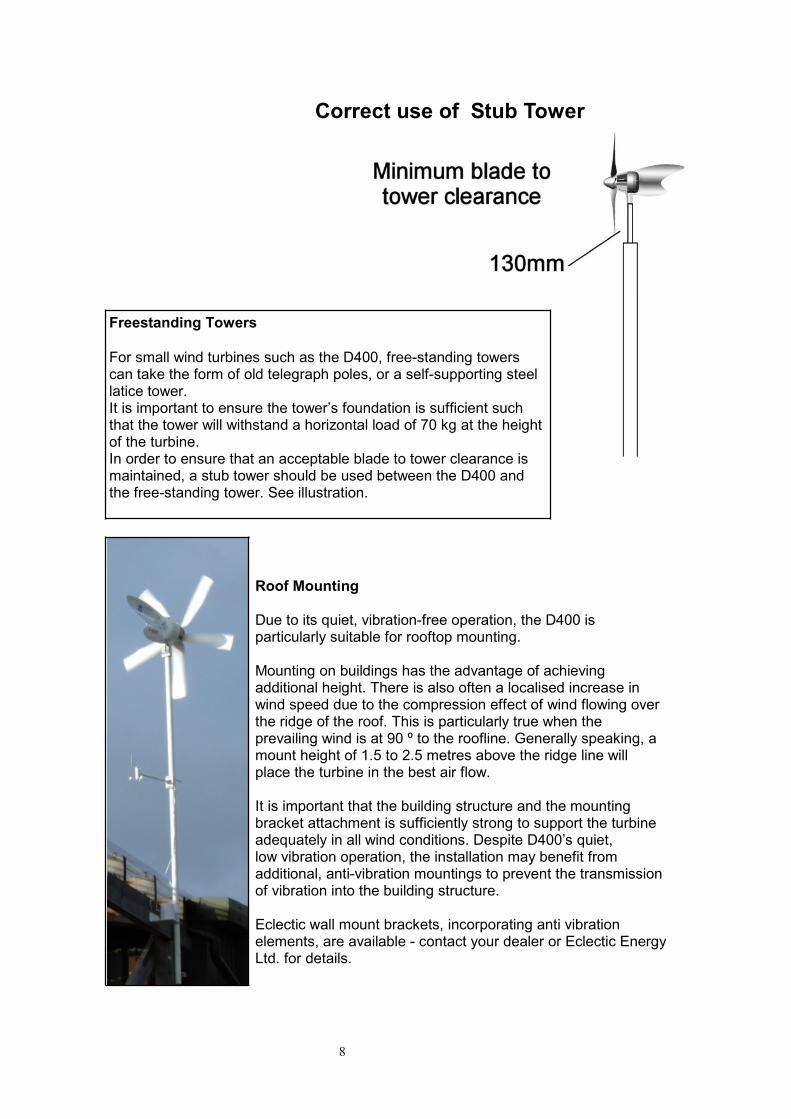
Correct use of Stub Tower
Freestanding Towers
For small wind turbines such as the D400, free-standing towerscan take the form of old telegraph poles, or a self-supporting steellatice tower.It is important to ensure the tower’s foundation is sufficient suchthat the tower will withstand a horizontal load of 70 kg at the heightof the turbine.In order to ensure that an acceptable blade to tower clearance ismaintained, a stub tower should be used between the D400 andthe free-standing tower. See illustration.
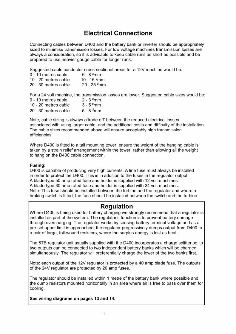
Roof Mounting
Due to its quiet, vibration-free operation, the D400 isparticularly suitable for rooftop mounting.
Mounting on buildings has the advantage of achievingadditional height. There is also often a localised increase inwind speed due to the compression effect of wind flowing overthe ridge of the roof. This is particularly true when theprevailing wind is at 90 º to the roofline. Generally speaking, amount height of 1.5 to 2.5 metres above the ridge line willplace the turbine in the best air flow.
It is important that the building structure and the mountingbracket attachment is sufficiently strong to support the turbineadequately in all wind conditions. Despite D400’s quiet,low vibration operation, the installation may benefit fromadditional, anti-vibration mountings to prevent the transmissionof vibration into the building structure.
Eclectic wall mount brackets, incorporating anti vibrationelements, are available - contact your dealer or Eclectic EnergyLtd. for details.

9
Assembling the D400Your D400 is supplied in two cartons. Unpack these and checkthe parts against the list at the beginning of this manual.
� Assemble the air rotor by sliding together the keys andmortises at the hub of the five air blades.
� Take the white, powder-coated hub plate, pass two 5mm boltsand washers through the inner holes, and fit the rotor hubspacer over the 5mm bolt heads.
� With the body of the wind generator on its back, offer the hubassembly up, and slide it onto the alternator shaft.
� Align holes in the rotor hub spacer with the 6mm holes inthe alternator shaft and secure with two 6mm cap head alanbolts provided .Its vital that a smear of threadlock compound is applied to
the threads to prevent the bolts from working loose inoperation.* Take care not to overtighten these bolts * as this cancause the air rotor to run out of ‘true’.
� An aluminium ring is provided to locate the blade rootssecurely. The ring is inserted, rounded side first, into themoulded annular recess on the rear of the blade roots.
Offer rotor blade assembly up to rotor hub spacer and slide intoplace.
� Ensure that the rotor assembly is fitted the right way round.The annular groove on the blade roots should face the rear (tailend) of the machine, and the face with the 10 conical holes inthe blade roots should face forwards.
� Fit outer stainless steel hub plate, place nuts and washers oninner 5mm bolts and tighten gently.
� Rotate air rotor in relation to hub until the five blade securingholes align.
� Pass a 5mm bolt through the inner powder-coated plate suchthat it passes right through the rotor blade and outer hub plate,fitting a washer and nut each time.
� Finally, evenly tighten all fasteners.Note that the rotor should only be secured using new nyloc nuts.

10
Assembling the D400 (continued)� Place the turbine face down on its rotor, and attach the tailusing the three M6 nuts and bolts provided. Note that the tailshould be fitted to the left-hand face of the casting flangewhen the D400 is viewed from the rear. The large stainlesssteel washers should also be fitted on the left-hand side.
� To fit the nose cone, offer up the axial splits in themoulding to the leading edges of the blades while holding the conesquare and central over the hub. Gently open each of the axial splits,and encourage it to pass over the leading edge of the blades.
� Finally, rotate the nose cone anti-clockwise such that iteffectively screws onto the blade roots. Snap the rear edge of theblades slot behind the trailing edge of the five blades (see pictures).
�� Fitting D400 to the Tower
Remove the tower liner from the D400’s yaw shaft, and check it for fitwith the proposed mounting tower. It is far preferable to discover itdoes not fit at this juncture rather than when you are actuallyattempting installation. The standard tower liner has an outsidediameter of 41.5 mm and is designed to slide into standardaluminium or steel scaffolding tubing with a nominal outside diameterof 48mm and inside diameter of 42 mm.
� The tower liner is retained to the yawshaft by three grub screws. Once themachine has been installed, the towerliner should be secured by drilling twoholes through the top of the tower into thetower liner to a depth of 12mm with a4mm drill, finally securing withtwo 8 x12mm self-tapping screws.
Should the tower liner not fit the tower tube correctly, consider sourcing an alternativemount tower or contact your supplier to order an alternative tower liner.On no account attempt an installation where the tower liner is a ‘sloppy’ fit in the tower,as this will lead to instability when the machine is operating, and could lead tomachine damage.
Your D400 is now ready for installation
11
Electrical ConnectionsConnecting cables between D400 and the battery bank or inverter should be appropriatelysized to minimise transmission losses. For low voltage machines transmission losses arealways a consideration, so it is advisable to keep cable runs as short as possible and beprepared to use heavier gauge cable for longer runs.
Suggested cable conductor cross-sectional areas for a 12V machine would be:0 - 10 metres cable 6 - 8 ²mm10 - 20 metres cable 10 - 16 ²mm20 - 30 metres cable 20 - 25 ²mm
For a 24 volt machine, the transmission losses are lower. Suggested cable sizes would be:0 - 10 metres cable 2 - 3 ²mm10 - 20 metres cable 3 - 5 ²mm20 - 30 metres cable 5 - 8 ²mm
Note, cable sizing is always a‘trade off’ between the reduced electrical lossesassociated with using larger cable, and the additional costs and difficulty of the installation.The cable sizes recommended above will ensure acceptably high transmissionefficiencies
Where D400 is fitted to a tall mounting tower, ensure the weight of the hanging cable istaken by a strain relief arrangement within the tower, rather than allowing all the weightto hang on the D400 cable connection.
Fusing:D400 is capable of producing very high currents. A line fuse must always be installedin order to protect the D400. This is in addition to the fuses in the regulator output.A blade-type 50 amp rated fuse and holder is supplied with 12 volt machines.A blade-type 30 amp rated fuse and holder is supplied with 24 volt machines.Note: This fuse should be installed between the turbine and the regulator and where abraking switch is fitted, the fuse should be installed between the switch and the turbine.
RegulationWhere D400 is being used for battery charging we strongly recommend that a regulator isinstalled as part of the system. The regulator’s function is to prevent battery damagethrough overcharging. The regulator works by sensing battery terminal voltage and as apre-set upper limit is approached, the regulator progressively dumps output from D400 toa pair of large, foil-wound resistors, where the surplus energy is lost as heat.
The 6TB regulator unit usually supplied with the D400 incorporates a charge splitter so itstwo outputs can be connected to two independent battery banks which will be chargedsimultaneously. The regulator will preferentially charge the lower of the two banks first.
Note: each output of the 12V regulator is protected by a 40 amp blade fuse. The outputsof the 24V regulator are protected by 20 amp fuses.
The regulator should be installed within 1 metre of the battery bank where possible andthe dump resistors mounted horizontally in an area where air is free to pass over them forcooling.
See wiring diagrams on pages 13 and 14.

12
Stopping the D400The D400 is a robust machine and can safely be left operating in most windspeeds.However, where extreme storm force winds are forecast, it is prudent to stop the machineand secure the rotor blades with a rope lashing.The D400 can be stopped by gripping the tail and turning the machine out of the wind,securing the blades once they have stopped rotating.Braking Switch:A braking switch can be fitted which provides a convenient aid to stopping the D400.The switch should be a double throw ‘break before make’ type, rated at least at40 amps. When operated, the switch disconnects the batteries from the D400before short-circuiting the turbine.The short circuit slows the rotor blades making it easier to turn the machine out of the windand to secure the blades.
Please note: the D400 utilises a purpose-designed, highly efficient,axial field ironlessalternator. This configuration delivers exceptional power outputs coupled with smooth, lowfriction running. These attributes are retained to some extent when the braking switch isapplied, and in consequence the electro magnetic braking effect is not as marked as withother machines of more conventional alternator design.In certain conditions, the rotor can overcome the braking effect altogether, whichresults in damagingly high currents being produced in the stator windings.
For this reason the braking switch should only be used to slow the unit prior tomanually stopping it. It is not a parking switch. If the machine is left to run with thebraking switch engaged, serious damage can occur to the generator.
PLEASE NOTE
The braking switch should onlybe used to slow the unit prior to
manually stopping it andsecuring the airblades with a
lashing.
If the machine is left in high windswith the braking switch engaged,
serious damage can occur.

13
Electrical Installation
It is recommended that theD400 is hard wired to the battery system.
In yacht installations, the cable should enter the yacht viaa cable gland.Deck plugs and sockets should not be used as theyrepresent a shock hazard if they accidentally becomedisconnected.
If in doubt, refer to a competentelectrical engineer or the manufacturers.
Single battery bankinstallation
The D400 should always beconnected to a battery when inuse, otherwise a dangerouslyhigh voltage can be generatedat the output cable.
Unregulated installation
*For fuse sizes,see note on page 11.

14
Electrical Installation
Connect the output cable to the battery bank(s) usingthe suggested wiring diagrams for guidance.
Remember to observe the correct polarity.
RED to POSITIVE + and BLACK to NEGATIVE –Where a battery monitor
is fitted
If your electrical system is fittedwith a digital battery monitor, itwill be driven by a shunt which istypically installed close to thebatteries.One side of the shunt isconnected directly to a batteryterminal.All other connections are madeto the opposite side of theshunt, or a busbar associatedwith it.The shunt is most usuallyconnected in the negative line.When wiring the D400 to asystem fitted with a shunt,observe polarity and connect theappropriate D400 outputcable to the non-battery side ofthe shunt.Again observing polarity, theother D400 output cable shouldbe made directly to the batteryterminal.The D400’s output will now passthrough the shunt and thebattery monitor will display areading.If the shunt is bypassed byconnecting both positive andnegative output leads from theD400 directly to the battery, themeter will fail to ‘see’ the D400,and register no output.
The D400 is fitted with 4.5 ²mm output fly leadsRefer to page 11 for suggested connection cable sizes
Twin Battery Bank Installation
*For fuse sizes,see note on page 11.

15
Performance and expectationsThe D400 is extremely efficient by design, making it the most powerful and productivewind generator of its rotor size currently available.
The D400 should perform in line with, or exceed, the values given in the output graph.When verifying system performance, it is important that wind speed measurements aretaken at the same height as the turbine, and that the batteries are at least 40% dis-charged.Note also that if a regulator is installed as part of the system, dumped output will not beseen by shunt-sensed battery monitors.
Should outputs be well below expectations, first suspect turbulence in the wind stream.Turbulence at a given site can be specific to a particular wind direction where it iscaused by an obstruction either up or downwind of the turbine. When the wind directionchanges, and the obstruction is no longer in line with the turbine, outputs may return toexpected levels. If the turbulent wind stream is not from the prevailing wind direction,this may not be important. Alternatively, the D400 could be re-sited or raised in height.
If poor output cannot be attributed to site conditions, re-check the whole installationagainst the wiring diagram and also look for poor or loose connections.
Check that the relevant connection from your D400 to the batteries is made to the non-battery side of the battery monitor shunt. If the connections are made direct to thebattery terminals, bypassing the shunt, the ship’s battery monitor will not be able to readthe D400’s output.
Note, where batteries are in a good state of charge, power diverted by the regulator tothe dump resistors will not be seen by the battery monitor.
Finally, ensure that the battery bank is in good condition. Check individual batteryterminal voltages within the bank. Defective cells within a battery bank are a commoncause of poor charging performance.
Note that there is a short period of ‘running in’ with a new wind turbine. The bearingsand shaft seals of a new machine take 40 – 50 hours of operation before mechanicalfriction falls to its design level. As a result, your D400 may seem a little slow to respondin light winds until this ‘running in’ period has passed.
Before deciding that your D400 is faulty, please work through the ‘trouble shooting’guide on page 16. In our experience, 9 out of 10 problems reported prove to be faults inthe installation rather than a problem with the turbine itself.
Please feel free to contact your dealer or Eclectic Energy Ltd. if you require additionaladvice or guidance.

16
D400 Trouble-shooting – Points to check if you think there’s a problem
Mechanical checks:� Spin the air blades by hand - they should rotate smoothly and freely with no hard spots.� Listen for any grinding, scraping or rumbling noises - these would indicate failed bearings
or contact between rotating parts inside the alternator.� Note: if the air rotor rotates smoothly and silently, but feels stiff (like turning something in
glue), refer to the electrical section on short circuits.� Next, try rotating the D400 around its yaw axis. Again, it should turn smoothly and freely
with no hard spots. If the yaw action is stiff or accompanied by undue noise, suspect theyaw bearings or the bush and slip ring assembly (see electrical section below).
� Check that the air blades are fitted the right way round, with the concave surface facingforward, i.e. towards the wind.
� Also, establish that the air hub is secure on the alternator shaft and that the air rotor doesnot ‘wobble’ due to wear at the hub.
� Finally, check that all fasteners are tight and secure.
Electrical checks:Very often poor turbine performance is traced to a problem elsewhere in the installation ratherthan a fault with the wind generator itself.� First check that both the D400 and the regulator are the correct voltage for the electrical
system. Both items have identification labels showing the voltage, typically 12 or 24 volt.� The most common cause of low outputs are loose or corroded connections in the output
cabling. Check and re-make all connections from turbine to battery. Seawater andelectricity are not a good combination, and connections deteriorate very quickly when wet.
� Next, check the turbine by measuring its open circuit voltage. Disconnect the unit as closeto the turbine as possible. If it is not too difficult, remove the turbine from its tower andmeasure at the fly lead cables exiting the yaw shaft of the machine itself.
� With a multi-meter set to the 20 volt DC range, connect the red positive meter lead to thered output, the black meter lead to the black output, and spin the unit by hand. On a 12VD400, you should be able to produce 4, 5 or even 6 volts, depending on how hard you spin.If you see voltages in this range, then the D400 is probably OK. If the D400 has an internalfault such as a missing phase in its alternator, then you will not be able to produce morethan one or two volts.
� Assuming the output voltage is OK, try rotating the yaw shaft (where the cables exit) whilstcontinuing to spin the rotor. If the voltage varies or disappears as you rotate the yaw shaft,the brushes and slip rings require cleaning. Equally, if the voltage remains steady, but theyaw shaft is unduly stiff or squeaks when rotated, the brushes and slip rings would benefitfrom cleaning.
� If the turbine checks out OK on the voltage test, suspect the rest of the installation. Checkeach wiring connection for corrosion, tightness and security as well as the fuses, fuseholders etc.
� If a regulator bypass switch is incorporated within the installation, check that this is wired inaccordance with the diagram contained in the D400 regulator instructions. Note that asimilar switch can be used as a braking switch, and the wiring for this is shown on page 12of the D400 User's Manual. Ensure that the two options have not been confused.
� Note that the ship's battery monitor is driven by a shunt, which will be mounted close to thebatteries. Ensure the D400 is connected to the non-battery side of the shunt. If it is not,then the D400 output will not be seen by the meter.
� Also, the D400 regulator incorporates a charge splitter (i.e has two outputs). If one of theseis connected to the service battery bank and one to the cranking battery or windlassbattery, it is possible that power from the D400 is flowing to them in preference to theservice bank. Try connecting both regulator positive outputs together and on to the servicebank to see if that improves matters.
� Finally, put a dedicated ammeter in the positive line between turbine and regulator. Thisshould read all current from the D400, including any diverted to the regulator dump loads.

17
Trouble-shooting continued - Poor Yaw Action:
� Stiffness in yaw; the D400 will not rotate to face the wind– check for any physical obstructions and the action of the yaw shaft. If the yawshaft does not rotate freely, suspect damaged or corroded yaw bearings, damagedor corroded slip rings/brush assembly or possibly a bent yaw shaft.
� Erratic yaw action; the D400 turns off the wind and is unstable– the D400 is normally very stable in yaw. If the turbine appears to ‘hunt around’ itsaxis, this could be due to turbulence in the airflow. If so, the problem shoulddisappear when the wind changes direction or the yacht is in a different location.Check that the D400 is properly secured to the mount tower. There should be noundue play between the turbine and the tower. Also, ensure that the tower isvertical and sufficiently rigid. If the tower is too flexible and bends excessivelyunder wind loading, it should be braced or guyed to stiffen it.
� Open Circuit; this is a major cause of poor yaw action, indicating that the turbine isnot properly connected to the batteries.- in this open circuit condition, the air rotor will over speed and the air blades willbecome uncharacteristically noisy, emitting a whistling noise. The D400 willfrequently turn off the wind, rotating through 360 ° on occasion. Check all wiring,looking for poor or broken connections. Also check fuses. If the fault remains,bypass the regulator to rule out regulator malfunction as the cause of the problem.
� Intermittent or occasional erratic yaw action– this could be due to an intermittent electrical fault. If you observe turbine outputabruptly dropping out and then suddenly returning, this could indicate a poorconnection between the brushes and slip rings.To service, remove the four self-tapping screws that secure the black brush-holderplate. Remove the brush-holder plate, taking care not to displace the brushes orbrush springs.The slip rings and contact faces of the brushes can then be cleaned with a solvent-soaked cloth or fine, wet and dry paper.
� Squeaking or grating noises audible in yaw– this could be caused by damaged yaw bearings. More typically, it is caused bydirt or corrosion on the slip rings/ brushes.Remove the brush-plate as above. If noise is still present with the brush-plate clearof the housing, suspect yaw bearings. If the squeak has gone, it confirms the noiseemanates from the brush and slip ring assembly. Clean these parts as in the lastsection. Also, using a fine file, remove any sharp edges from the contact surfacesof the brushes.On re-assembly, the yaw shaft should rotate silently. If a squeak is still evident,remove the brush plate again and spray the slip rings and brushes with anelectrical lubricant (WD40 or similar) or smear a little silver-loaded grease on theslip rings.

18
Undue mechanically transmitted noise or vibration
� Noise or vibration transmitted down the shaft– suspect a loose air rotor. Grasp an air blade and rock the rotor to check if there isany relative movement between the air rotor and the alternator shaft. If play is felt,remove hub parts and re-build, fitting a new hub liner.
� Correct fit of nose cone– check that the nose cone is not catching on the alternator housing.
� Air blade damage– check that the blades are not damaged or chipped. This may put the rotor out ofbalance. Replace air blades as necessary.
� Tail bolts– check tail bolts are tight.
� Noises from the alternator– rotate the air blades slowly and listen at the alternator housing. Grating orscraping noises indicate a fault within the alternator.Refer to your dealer or Eclectic Energy Limited.
19
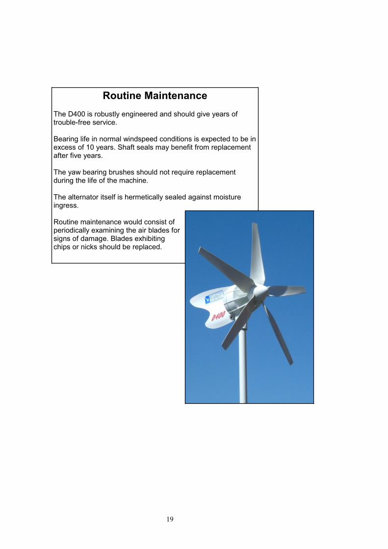
Routine MaintenanceThe D400 is robustly engineered and should give years oftrouble-free service.
Bearing life in normal windspeed conditions is expected to be inexcess of 10 years. Shaft seals may benefit from replacementafter five years.
The yaw bearing brushes should not require replacementduring the life of the machine.
The alternator itself is hermetically sealed against moistureingress.
Routine maintenance would consist ofperiodically examining the air blades forsigns of damage. Blades exhibitingchips or nicks should be replaced.

20
www.eclectic-energy.co.uk
DECLARATION OF CONFORMITY
We declare that this product complies with thefollowing standards/directives:
89/336/EEC
Product description: D400 Alternator
Model number: EE400
Serial number:
Signed:
Eclectic Energy LimitedUnit 22 Sherwood NetworkcentreSherwood Energy VillageOllertonNottinghamshireNG22 9FD +44 (0) 1623 821535United Kingdom [email protected]
GUARANTEE
The D400 Wind Generator is guaranteed against faulty parts and manufacture fora period of two years from date of purchase.
The unit should be returned prepaid to:
Eclectic Energy Ltd, Unit Sherwood Networkcentre, Sherwood Energy VillageOllerton, Nottinghamshire, NG22 9FD, United Kingdom
Damage caused by mishandling, faulty installation or accident is not covered.Eclectic Energy can not be liable for damage caused by the D400 in the event of
accidental contact, incorrect installation or insufficient care.
However, Eclectic Energy Limited is committed to provide after sales care as fullyand efficiently as possible in order to support our customers.

D400 Wind Turbine SpecificationsPerformance & Rated power 235 W @ 11m/s (22 knots), 420 W @ 14 m/s (28 knots)Power outputs Maxiumum power 600 + W
Rotational speed 1100 rpm @14m/sCut-in speed 2.5m/s (Knots)Cut-out wind speed None
Turbine features Turbine type Horizontal axis upwindNumber of blades 5Airfoil type Low Reynolds - variable camberDiameter of turbine 1.1mSwept area 0.95 sq. mTip speed ratio 4Typical noise level 2-6 dbA over backgroundBlade material Glass-filled nylon
Alternator Alternator type Direct drive - axial fieldfeatures 12 pole permanent magnet generator
Design 3-phase AC with rectificationOutputs direct current (DC)Annular high energy magnet rotorsEncapsulated stator windings
Voltages available DC: 12V, 24V, 48V, 72VAC: 240V grid connect via inverter
Materials Aluminium alloy housing, hermetically sealedAlocrom 1200 corrosion protection and polyester powder coat316 stainless steel shafts and A4 stainless fastners
EMI (electromagneticemissons) C.E. compliant
MCS Accreditation PendingControl system Stall regulationBrake system Electromagnetic braking switch
Yaw System Passive Low resonance, formed aluminim tailHeavy duty slip ring assembly with saddle spring loaded outputbrushes
Turning circle 700mmMounting Typical stub tower 50mm - 75mm O/DWeight Total 17kgFinish Colours available White with white blades
Black with translucent


