D3.2.6-1 Refinement of Model Transformation Rules€¦ · D3.2.6-1 Refinement of model...
23
D3.2.6-1 Refinement of model transformation rules Date : 14/Nov/2007 Author : UPD, Intecs Issue : 1 Rev : 0 ID : 004033.DDHRT.UPD.DVRB.08 Project IST-004033 ASSERT Automated proof based System and Software Engineering for Real-Time Applications Instrument: IST [FP6-2003-IST-2 4.3.2.5] Thematic Priority: Embedded Systems Deliverables D3.2.6-1 Refinement of Model Transformation Rules from Use Experience in V2 Demonstrator Work Package: WP3.2 Due date of deliverable: M33 Actual submission date: 22/October/2007 Start date of Project: September 5 th 2004 Duration: 3 years Organisation name of lead Contractor for this deliverable: UPD Issue – Revision I1R0 Project co-funded by the European Commission within the Sixth Framework Programme (2002-2006) Dissemination Level PU Public X PP Restricted to other programme participants (including the Commission Services) RE Restricted to a group specified by the consortium (including the Commission Services) CO Confidential, only for members of the consortium (including the Commission Services) 004033.DDHRT.UPD.DVRB.08.I1R0.D3.2.6-1 last modified: 14/11/2007 18:11:00 PM page 1 of 23
Transcript of D3.2.6-1 Refinement of Model Transformation Rules€¦ · D3.2.6-1 Refinement of model...
D3.2.6-1 Refinement of model transformation rules Date : 14/Nov/2007 Author : UPD, Intecs Issue : 1 Rev : 0 ID : 004033.DDHRT.UPD.DVRB.08
Project IST-004033
ASSERT
Automated proof based System and Software Engineering for Real-Time Applications
Instrument: IST [FP6-2003-IST-2 4.3.2.5] Thematic Priority: Embedded Systems Deliverables D3.2.6-1 Refinement of Model Transformation
Rules from Use Experience in V2 Demonstrator Work Package: WP3.2 Due date of deliverable: M33
Actual submission date: 22/October/2007
Start date of Project: September 5th 2004 Duration: 3 years
Organisation name of lead
Contractor for this deliverable: UPD
Issue – Revision I1R0
Project co-funded by the European Commission within the Sixth Framework Programme (2002-2006)
Dissemination Level
PU Public X
PP Restricted to other programme participants (including the Commission Services)
RE Restricted to a group specified by the consortium (including the Commission Services)
CO Confidential, only for members of the consortium (including the Commission Services)
004033.DDHRT.UPD.DVRB.08.I1R0.D3.2.6-1 last modified: 14/11/2007 18:11:00 PM page 1 of 23
D3.2.6-1 Refinement of model transformation rules Date : 14/Nov/2007 Author : UPD, Intecs Issue : 1 Rev : 0 ID : 004033.DDHRT.UPD.DVRB.08
Refinement of Model Transformation Rules from Use Experience in V2 Demonstrator
Distribution: TSC, DDHRT, all Project, EC
Prepared by: Matteo Bordin, Marco Panunzio (UPD), Silvia Mazzini, Stefano Puri (Intecs)
Checked by: Tullio Vardanega (UPD)
Release type: External Public Release
Status: Passed QPR/IPR
Disclaimer
This document contains material, which is the copyright of certain ASSERT consortium parties, and may not be reproduced or copied without permission.
• In case of Public (PU): All ASSERT consortium parties have agreed to full publication of this document.
• In case of Restricted to Programme (PP): All ASSERT consortium parties have agreed to make this document available on request to other framework programme participants.
• In case of Restricted to Group (RE): All ASSERT consortium parties have agreed to full publication of this document to a restricted group. However this document is written for being used by all interested projects, organisations and individuals.
• In case of Consortium confidential (CO): The information contained in this document is the proprietary confidential information of the ASSERT consortium and may not be disclosed except in accordance with the consortium agreement.
The commercial use of any information contained in this document may require a license from the proprietor of that information.
Neither the ASSERT consortium as a whole, nor a certain party of the ASSERT consortium warrant that the information contained in this document is capable of use, or that use of the information is free from risk, and accept no liability for loss or damage suffered by any person using this information.
004033.DDHRT.UPD.DVRB.08.I1R0.D3.2.6-1 last modified: 14/11/2007 18:11:00 PM page 2 of 23

D3.2.6-1 Refinement of model transformation rules Date : 14/Nov/2007 Author : UPD, Intecs Issue : 1 Rev : 0 ID : 004033.DDHRT.UPD.DVRB.08
Document Change Record
Issue Revision Date Affected
Section/Paragraph/Page Reason for Change/Brief Description of Change
I0R1 22/Oct/07 All First draft issue
I1R0 14/Nov/07 Abstract, Introduction, Conclusions Amended to address comments from the QPR/IPR
004033.DDHRT.UPD.DVRB.08.I1R0.D3.2.6-1 last modified: 14/11/2007 18:11:00 PM page 3 of 23
D3.2.6-1 Refinement of model transformation rules Date : 14/Nov/2007 Author : UPD, Intecs Issue : 1 Rev : 0 ID : 004033.DDHRT.UPD.DVRB.08
004033.DDHRT.UPD.DVRB.08.I1R0.D3.2.6-1 last modified: 14/11/2007 18:11:00 PM page 4 of 23
Table of Contents
1 ABBREVIATIONS ................................................................................................................................................. 6
2 INTRODUCTION................................................................................................................................................... 7
3 MAPPING HRT-UML/RCM TO THE ASSERT PROCESS............................................................................. 8 3.1 DEFINE LOGICAL ARCHITECTURE AND MODEL DATA ........................................................................................ 8 3.2 MODELLING HARDWARE .................................................................................................................................. 8 3.3 MAPPING SOFTWARE TO HARDWARE................................................................................................................ 8 3.4 GENERATING VM-LEVEL CONTAINERS ............................................................................................................ 8 3.5 FEASIBILITY ANALYSIS..................................................................................................................................... 9 3.6 GENERATION OF APPLICATION CODE ................................................................................................................ 9 3.7 SUMMARY ........................................................................................................................................................ 9
4 LOGIC AND READINESS OF TRANSFORMATION STEPS....................................................................... 10 4.1 FOUNDATIONS: THE NATURE OF APLC .......................................................................................................... 10 4.2 MODEL TRANSFORMATION............................................................................................................................. 14 4.3 GENERATION OF VMLC TYPES ...................................................................................................................... 14 4.4 GENERATION OF VMLC INSTANCES............................................................................................................... 16 4.5 MODEL- BASED ROUND-TRIP TIMING ANALYSIS ............................................................................................. 18 4.6 WORK IN PROGRESS........................................................................................................................................ 20
4.6.1 Support for operation modes .................................................................................................................... 20 4.6.2 Automated extraction of WCET estimates................................................................................................. 21 4.6.3 Complete modelling of the communication stack...................................................................................... 21
5 FEEDBACK EXPECTED FROM THE V3 DEMONSTRATORS.................................................................. 22
D3.2.6-1 Refinement of model transformation rules Date : 14/Nov/2007 Author : UPD, Intecs Issue : 1 Rev : 0 ID : 004033.DDHRT.UPD.DVRB.08
ABSTRACT This report is one of the M33 products of WP3.2, the work-package in the DDHRT cluster which focuses on the development of the model transformation infrastructure in support of the property-preserving model-driven engineering approach proposed by the cluster for ASSERT. This report, which is produced while work on the V3 demonstrators has only just commenced, has a threefold purpose: (1) it maps the model transformation logic embedded in the HRT-UML/RCM toolset to the ASSERT Process as described by the P&S cluster in D2.3-1, which is intrinsically the result of the consolidation work performed with the V2 demonstration milestone; (2) it shows the level of maturity of the said model transformation logic as it stands at the start of the V3 demonstration work, which is itself the product of the consolidation from the lessons learned with the V2 demonstration milestone; (3) it enumerates the feedback and the returns expected from the V3 demonstrators, the culminating moment of the ASSERT project, which may serve to improve the fitness of the proposed HRT-UML/RCM concept and infrastructure. Work in WP3.2 is not limited to the development of the HRT-UML/RCM toolset infrastructure. Parallel work aimed at identical goals is being conducted using AADL as the pivot formalism. It is therefore expected that a mirror report, along the very same lines as the present one, will be produced by the AADL team in WP3.2, as soon as the development work to feed the V3 demonstrators will have completed.
004033.DDHRT.UPD.DVRB.08.I1R0.D3.2.6-1 last modified: 14/11/2007 18:11:00 PM page 5 of 23
D3.2.6-1 Refinement of model transformation rules Date : 14/Nov/2007 Author : UPD, Intecs Issue : 1 Rev : 0 ID : 004033.DDHRT.UPD.DVRB.08
1 Abbreviations AADL SAE Architecture Analysis and Design Language ABB Application Building Block APLC Application-level container ASN.1 Abstract Syntax Notation One ATL Atlas Transformation Language DDHRT Dependability Distributed and Hard Real Time HRT Hard Real Time MPC Multiple Platform Coordination MTS Message Transfer Service OBCS Object Control Structure PI Provided Interface PP Pilot Project RCM Ravenscar Computational Model RI Required Interface UML Unified Modelling Language VM Virtual Machine VMLC VM-level container
004033.DDHRT.UPD.DVRB.08.I1R0.D3.2.6-1 last modified: 14/11/2007 18:11:00 PM page 6 of 23
D3.2.6-1 Refinement of model transformation rules Date : 14/Nov/2007 Author : UPD, Intecs Issue : 1 Rev : 0 ID : 004033.DDHRT.UPD.DVRB.08
2 Introduction The title of this deliverable report as stipulated in Annex 1 suggests that emphasis should be placed on the lessons learned on the model transformation logic from the V2 demonstration milestone. In actual fact, the incremental demonstration logic adopted in Phase II of the ASSERT project, which was meant to progress from the feasibility-geared V1 demonstrator in September 2006, via the consolidation-oriented V2 demonstrator in March 2007, to the evaluation-seeking V3 demonstrator due in December 2007, has translated into in obvious escalation in the relevance and strategic importance of the demonstrators. On this account, the authors of this report have considered that discussing (1) whether, (2) to what extent and (3) with what expectations the model transformation logic at the core of the Model-Driven Engineering approach to the ASSERT development process is ready to feed the V3 demonstration exercise is more interesting and worthwhile than discussing lessons learned from a partial and incremental stage in the route to attaining the project objectives. For this reason, this deliverable report takes stock of the technical situation of the project (seen from the HRT-UML/RCM side of things) at the end of September 2007, when preparation for the V3 demonstration stage is just beginning and discusses:
1. how the ASSERT process (as currently understood, and thus prior to the consolidation expectedly attained with the V3 demonstration) is reflected in the HRT-UML/RCM model transformation logic
2. the level of maturity currently achieved by the model transformation logic as implemented in the HRT-UML/RCM infrastructure
3. the areas and issues on which feedback from the V3 demonstration exercise is considered most critical to the final refinement of the HRT-UML/RCM technology infrastructure and the industrial prospects of the methodological vision it pursues.
004033.DDHRT.UPD.DVRB.08.I1R0.D3.2.6-1 last modified: 14/11/2007 18:11:00 PM page 7 of 23

D3.2.6-1 Refinement of model transformation rules Date : 14/Nov/2007 Author : UPD, Intecs Issue : 1 Rev : 0 ID : 004033.DDHRT.UPD.DVRB.08
3 Mapping HRT-UML/RCM to the ASSERT Process In this section we describe the current support provided by the HRT-UML/RCM Methodology and the related tool to the applicable software development ASSERT process areas as described in D2.3-1 (ASSERT Process Definition).
3.1 Define logical architecture and model data HRT-UML/RCM fully supports the graphical modelling of the logical architecture, including the modelling of data. The functional view supports the identification of logical blocks and the definition of the ABB functional blocks: the ABB detail design is statically defined through the usage of a class and interface diagrams while the sequential behaviour is modelled using state machine diagrams with the application of the framework profile developed by ETH in WP4.2. The data view definition is supported according to the data type definition appearing in the RCM metamodel. The RCM metamodel is compatible with the ASN.1 data definition: model transformations from ASN.1 to the RCM metamodel are provided (via a asn2uml bridge). The interface view supports the definition of Application Level Components (APLC) which embed the ABB: the non-functional properties of the APLC can be defined and APLC can be interconnected through their provided and required interfaces. Specific class and instance diagrams are provided to support these activities.
3.2 Modelling hardware HRT-UML/RCM fully supports this process through the usage of the deployment diagram where entities like computational node, processor and memory can be defined.
3.3 Mapping software to hardware HRT-UML/RCM fully supports the mapping of APLC instances to partitions and computational nodes: an APLC instance can be mapped to a partition and a partition can be mapped to a computational node, where the mapping sequence is not relevant and the order can be changed.
3.4 Generating VM-level Containers HRT-UML/RCM supports automated transformation from APLC to VM-level containers (VMLC). From the user standpoint this step need not be invoked explicitly; in fact it is automatically performed by the tool and its results are automatically given as input to the subsequent steps of the process (that is, feasibility analysis and generation of application code). Those two steps are in fact the only transformations that the user can explicitly initiate from the graphical user interface of the tool from the deployment view.
004033.DDHRT.UPD.DVRB.08.I1R0.D3.2.6-1 last modified: 14/11/2007 18:11:00 PM page 8 of 23
D3.2.6-1 Refinement of model transformation rules Date : 14/Nov/2007 Author : UPD, Intecs Issue : 1 Rev : 0 ID : 004033.DDHRT.UPD.DVRB.08
3.5 Feasibility analysis HRT-UML/RCM integrates automated transformations geared for round-trip analysis: the tool enables the invocation of this process from a model where the interface view and the deployment view have been modelled completely. The results of the analysis are made visible in the user defined model (e.g. worst-case response time for APLC cyclic/sporadic services).
3.6 Generation of application code HRT-UML/RCM integrates automated transformations geared to the generation of Ada 2005 code which implements the system software model: the tool allows the user to invoke this transformation process from a model where the functional, interface and deployment view have been modelled completely (and, ideally, after model feasibility has been ascertained).
3.7 Summary HRT-UML/RCM integrates the automated RCM transformations and offers dedicated commands for their invocation, thereby facilitating their use. Whereas the HRT-UML/RCM tool has been built with the goal to insure that the correctness by construction principle holds at all times throughout the entire modelling process, some completeness and consistency preconditions should be verified on the input model in order for the transformations to be applied safely and correctly. The required precondition constraints (e.g., all the non-functional attribute values for APLC have to be specified) need an explicit validation process. HRT-UML/RCM offers a specific feature to support the check of precondition constraints that have been identified for the model to hold in the different views: the validation process is automatically started before any transformation step, such as launching round-trip analysis and code generation, so as to guarantee that that particular transformation step can be applied safely and successfully. The toolset User Manual provides a detailed list of the HRT-UML/RCM applicable constraints. The current validation mechanism could be enhanced. Currently the relevant constraints have been partitioned among the different modelling views and are always applied in all the different views. In the future it should be possible to validate each single view independently, according to the view-specific or user-selected set of constraints. For instance, when performing only functional code generation any error in the interface view (for instance regarding an incomplete APLC specification) should not be notified by the user.
004033.DDHRT.UPD.DVRB.08.I1R0.D3.2.6-1 last modified: 14/11/2007 18:11:00 PM page 9 of 23
D3.2.6-1 Refinement of model transformation rules Date : 14/Nov/2007 Author : UPD, Intecs Issue : 1 Rev : 0 ID : 004033.DDHRT.UPD.DVRB.08
4 Logic and readiness of transformation steps This section provides a concise yet detailed summary of the transformation process which automatically generates the concurrency view from the interface view and the deployment view. The discussion in this section complements the information on the HRT-UML/RCM toolset infrastructure presented in D3.1.4-1 (Guide for using AP-level modelling containers).
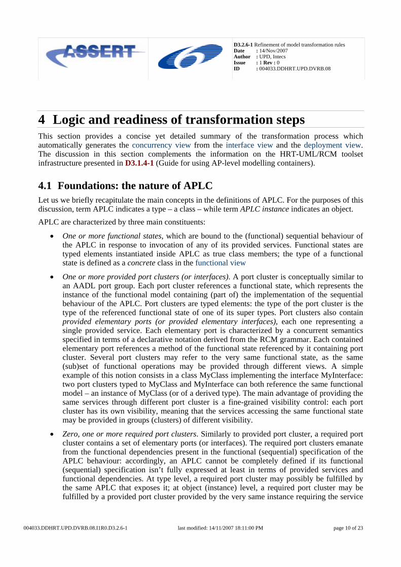
4.1 Foundations: the nature of APLC Let us we briefly recapitulate the main concepts in the definitions of APLC. For the purposes of this discussion, term APLC indicates a type – a class – while term APLC instance indicates an object. APLC are characterized by three main constituents:
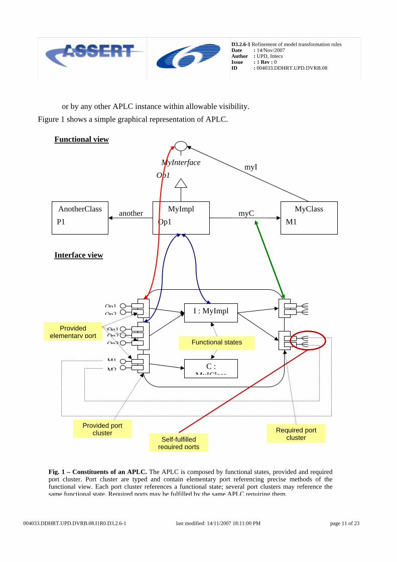
• One or more functional states, which are bound to the (functional) sequential behaviour of the APLC in response to invocation of any of its provided services. Functional states are typed elements instantiated inside APLC as true class members; the type of a functional state is defined as a concrete class in the functional view
• One or more provided port clusters (or interfaces). A port cluster is conceptually similar to an AADL port group. Each port cluster references a functional state, which represents the instance of the functional model containing (part of) the implementation of the sequential behaviour of the APLC. Port clusters are typed elements: the type of the port cluster is the type of the referenced functional state of one of its super types. Port clusters also contain provided elementary ports (or provided elementary interfaces), each one representing a single provided service. Each elementary port is characterized by a concurrent semantics specified in terms of a declarative notation derived from the RCM grammar. Each contained elementary port references a method of the functional state referenced by it containing port cluster. Several port clusters may refer to the very same functional state, as the same (sub)set of functional operations may be provided through different views. A simple example of this notion consists in a class MyClass implementing the interface MyInterface: two port clusters typed to MyClass and MyInterface can both reference the same functional model – an instance of MyClass (or of a derived type). The main advantage of providing the same services through different port cluster is a fine-grained visibility control: each port cluster has its own visibility, meaning that the services accessing the same functional state may be provided in groups (clusters) of different visibility.
• Zero, one or more required port clusters. Similarly to provided port cluster, a required port cluster contains a set of elementary ports (or interfaces). The required port clusters emanate from the functional dependencies present in the functional (sequential) specification of the APLC behaviour: accordingly, an APLC cannot be completely defined if its functional (sequential) specification isn’t fully expressed at least in terms of provided services and functional dependencies. At type level, a required port cluster may possibly be fulfilled by the same APLC that exposes it; at object (instance) level, a required port cluster may be fulfilled by a provided port cluster provided by the very same instance requiring the service
004033.DDHRT.UPD.DVRB.08.I1R0.D3.2.6-1 last modified: 14/11/2007 18:11:00 PM page 10 of 23
D3.2.6-1 Refinement of model transformation rules Date : 14/Nov/2007 Author : UPD, Intecs Issue : 1 Rev : 0 ID : 004033.DDHRT.UPD.DVRB.08
or by any other APLC instance within allowable visibility. Figure 1 shows a simple graphical representation of APLC.
Functional view
MyImplOp1
MyInterfaceOp1 O 2
I : MyImpl
MyClass M1
myC
myI
AnotherClass P1
Interface view
another
C : MyIClass
Op1Op2
Op1Op2Op3
M1M2
Functional states
Provided port cluster
Provided elementary port
Required port cluster Self-fulfilled
required ports
Fig. 1 – Constituents of an APLC. The APLC is composed by functional states, provided and required port cluster. Port cluster are typed and contain elementary port referencing precise methods of the functional view. Each port cluster references a functional state; several port clusters may reference the same functional state. Required ports may be fulfilled by the same APLC requiring them.
004033.DDHRT.UPD.DVRB.08.I1R0.D3.2.6-1 last modified: 14/11/2007 18:11:00 PM page 11 of 23
D3.2.6-1 Refinement of model transformation rules Date : 14/Nov/2007 Author : UPD, Intecs Issue : 1 Rev : 0 ID : 004033.DDHRT.UPD.DVRB.08
The concurrent semantics of APLC provided elementary port may be decided choosing one of the following values:
• Cyclic: represents a parameter-less deferred service automatically executed by a dedicated task released on a constant period by the system clock.
• Sporadic: represents a deferred service whose invocation entails the buffering of the parameters and the release of a dedicated sporadic task to handle the request. The release protocol of the sporadic task enforces a minimum interval between subsequent invocations.
• Modifier: represents non-nominal deferred service. Modifiers can be used to map several operations onto the same physical task: a modifier is indeed always associated to a Sporadic or Cyclic service, which represent the nominal operation executed by the underlying task. The Modifier shares its release policy (time-triggered or event triggered) with its associated nominal service.
• Protected: represent an immediate service offering protection against concurrent access.
• Unprotected: represent an immediate service void of any concurrent semantics. If any two services access the same (static) variables, a main constraint holds for their concurrent semantics. Their concurrent semantics must in fact be one of the possible couples (the order is not important):
• Cyclic, Modifier
• Sporadic, Modifier
• Modifier, Modifier
• Protected, Protected
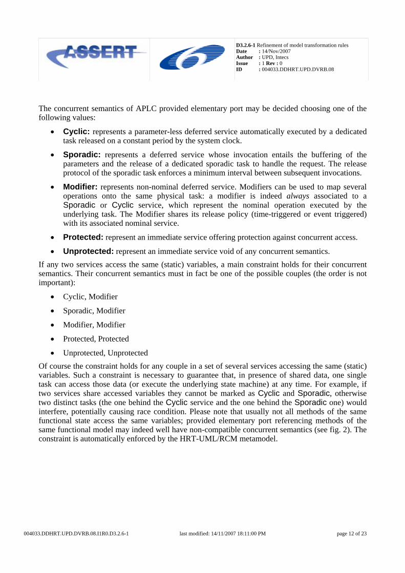
• Unprotected, Unprotected Of course the constraint holds for any couple in a set of several services accessing the same (static) variables. Such a constraint is necessary to guarantee that, in presence of shared data, one single task can access those data (or execute the underlying state machine) at any time. For example, if two services share accessed variables they cannot be marked as Cyclic and Sporadic, otherwise two distinct tasks (the one behind the Cyclic service and the one behind the Sporadic one) would interfere, potentially causing race condition. Please note that usually not all methods of the same functional state access the same variables; provided elementary port referencing methods of the same functional model may indeed well have non-compatible concurrent semantics (see fig. 2). The constraint is automatically enforced by the HRT-UML/RCM metamodel.
004033.DDHRT.UPD.DVRB.08.I1R0.D3.2.6-1 last modified: 14/11/2007 18:11:00 PM page 12 of 23
D3.2.6-1 Refinement of model transformation rules Date : 14/Nov/2007 Author : UPD, Intecs Issue : 1 Rev : 0 ID : 004033.DDHRT.UPD.DVRB.08
MyImpl- State1 : Type1 - State2 : Type2 + Op1 + Op2 + O 3
Op1 accesses State1;Op2 accesses State2;
I : MyImpl<<sporadic>> Op1
<<protected>> Op2
<<sporadic>> Op1 <<protected>> Op2 <<protected>> Op3
Fig. 2 – Concurrent semantics of provided elementary port. If two methods of the same functional model don’t share accessed variables, the concurrent semantics of the referencing elementary provided port can be non-compatible. Provided elementary port referencing the same method of the same functional state are forced to declare the same concurrent semantics (for example, Op1 and Op2).
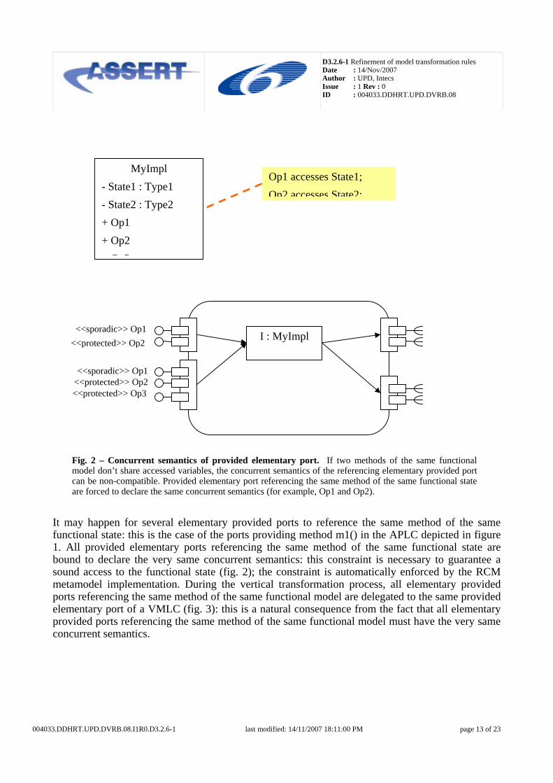
It may happen for several elementary provided ports to reference the same method of the same functional state: this is the case of the ports providing method m1() in the APLC depicted in figure 1. All provided elementary ports referencing the same method of the same functional state are bound to declare the very same concurrent semantics: this constraint is necessary to guarantee a sound access to the functional state (fig. 2); the constraint is automatically enforced by the RCM metamodel implementation. During the vertical transformation process, all elementary provided ports referencing the same method of the same functional model are delegated to the same provided elementary port of a VMLC (fig. 3): this is a natural consequence from the fact that all elementary provided ports referencing the same method of the same functional model must have the very same concurrent semantics.
004033.DDHRT.UPD.DVRB.08.I1R0.D3.2.6-1 last modified: 14/11/2007 18:11:00 PM page 13 of 23
D3.2.6-1 Refinement of model transformation rules Date : 14/Nov/2007 Author : UPD, Intecs Issue : 1 Rev : 0 ID : 004033.DDHRT.UPD.DVRB.08
<<sporadic>> Op1 <<protected>> Op2
<<sporadic>> Op1 <<protected>> Op2 <<protected>> Op3
Fig. 3 – Delegation to VMLC. If two provided elementary ports reference the same method of the same functional state, then they are delegated to the same provided port of the same VMLC (see for example, the two provided port providing Op1 and the two providing Op2).
VMLC
VMLC
4.2 Model transformation Model transformation is comprised of two main steps: the first one generates VMLC types implementing each APLC on top of a Ravenscar-compliant VM; the second one generates interconnected VMLC instances starting from interconnected APLC instances.
4.3 Generation of VMLC types The vertical transformation proceeds per functional state: the presence of multiple functional states does not affect the transformations: for this reason, our examples from now on mostly encompass APLC with a single functional state. During the transformation, each functional state is considered along with all the provided/required port clusters referencing it; all provided elementary ports referencing the same method of the same functional state are delegated to the same VMLC provided port. Since all provided elementary port referencing the same method of the same functional state must present the same concurrent semantics, we may well initially assume the existence of exactly a single provided port for each method of the functional state; moving to a more complex model is just a matter of scaling. VMLC are generated following a set of strict rules, which applies to provided elementary ports contained in the same provided port cluster:
Cyclicid, Modifier*{variates=id} ::= Cyclic(Cyclic, Modifier*) (1.1) A provided port marked as Cyclic and all Modifier referencing it generate a single cyclic VMLC providing all ports.
004033.DDHRT.UPD.DVRB.08.I1R0.D3.2.6-1 last modified: 14/11/2007 18:11:00 PM page 14 of 23
D3.2.6-1 Refinement of model transformation rules Date : 14/Nov/2007 Author : UPD, Intecs Issue : 1 Rev : 0 ID : 004033.DDHRT.UPD.DVRB.08
Sporadicid, Modifier*{variates=id} ::= Sporadic(Sporadic, Modifier*) (1.2) A provided port marked as Sporadic and all Modifier referencing it generate a single sporadic VMLC providing all ports.
Protected+ ::= Protected(Protected+) (1.3) All provided ports marked as Protected and contained by the same portcluster generate a single protected VMLC providing all ports.
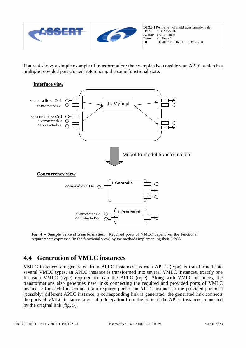
Unprotected+ ::= Passive(Unprotected+) (1.4) All provided ports marked as Unprotected and contained by the same portcluster generate a single Passive VMLC providing all ports. The required ports of a VMLC are directly and univocally determined by the functional requirements expressed (in the functional view) by the methods implementing the functional behaviour of its provided ports (see figure 4).
004033.DDHRT.UPD.DVRB.08.I1R0.D3.2.6-1 last modified: 14/11/2007 18:11:00 PM page 15 of 23
D3.2.6-1 Refinement of model transformation rules Date : 14/Nov/2007 Author : UPD, Intecs Issue : 1 Rev : 0 ID : 004033.DDHRT.UPD.DVRB.08
Figure 4 shows a simple example of transformation: the example also considers an APLC which has multiple provided port clusters referencing the same functional state.
I : MyImpl<<sporadic>> Op1<<protected>>
<<sporadic>> Op1<<protected>><<protected>>
Fig. 4 – Sample vertical transformation. Required ports of VMLC depend on the functional requirements expressed (in the functional view) by the methods implementing their OPCS.
I Sporadic
I Protected
<<sporadic>> Op1
<<protected>><<protected>>
Interface view
Concurrency view
Model-to-model transformation
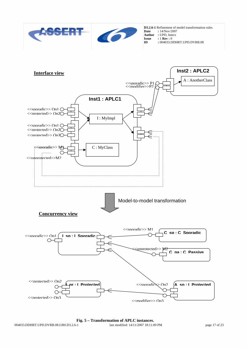
4.4 Generation of VMLC instances VMLC instances are generated from APLC instances: as each APLC (type) is transformed into several VMLC types, an APLC instance is transformed into several VMLC instances, exactly one for each VMLC (type) required to map the APLC (type). Along with VMLC instances, the transformations also generates new links connecting the required and provided ports of VMLC instances: for each link connecting a required port of an APLC instance to the provided port of a (possibly) different APLC instance, a corresponding link is generated; the generated link connects the ports of VMLC instance target of a delegation from the ports of the APLC instances connected by the original link (fig. 5).
004033.DDHRT.UPD.DVRB.08.I1R0.D3.2.6-1 last modified: 14/11/2007 18:11:00 PM page 16 of 23
D3.2.6-1 Refinement of model transformation rules Date : 14/Nov/2007 Author : UPD, Intecs Issue : 1 Rev : 0 ID : 004033.DDHRT.UPD.DVRB.08
004033.DDHRT.UPD.DVRB.08.I1R0.D3.2.6-1 last modified: 14/11/2007 18:11:00 PM page 17 of 23
I : MyImpl
C : MyClass
<<sporadic>> Op1<<protected>> Op2
<<sporadic>> M1
<<unprotected>>M2
Interface view
Fig. 5 – Transformation of APLC instances.
Inst1 : APLC1
A : AnotherClass<<sporadic>> P1<<modifier>>P2
Inst2 : APLC2
<<sporadic>> Op1<<protected>> Op2<<protected>> Op3
I sp : I Sporadic
I pr : I Protected
<<sporadic>> Op1
<<protected>> Op2
<<protected>> Op3
Concurrency view
A sp : I Protected<<sporadic>> Op2
<<modifier>> Op3
C sp : C Sporadic<<sporadic>> M1
C pa : C Passive<<unprotected>> M2
Model-to-model transformation
D3.2.6-1 Refinement of model transformation rules Date : 14/Nov/2007 Author : UPD, Intecs Issue : 1 Rev : 0 ID : 004033.DDHRT.UPD.DVRB.08
4.5 Model- based round-trip timing analysis The goal of the round-trip timing analysis is to perform timing analysis on a suitable representation of the system under development and to report back the results directly at model-level. The process associated to it shall provide seamless support to perform automatically all the required model transformations and other involved mechanisms and make the results available to the designer as information that complement the description of the system. The concurrency view encompasses a faithful representation of the system under development. VMLC types and instances are a representation of legal run-time entities abiding by the Ravenscar Computational Model. VMLC are complemented with:
• the description of the hardware of the system;
• the description of the relevant run-time platform mechanism and their cost;
• the (indirect) assignment of VMLC to logical partitions (in the deployment view each APLC instance is assigned to a single logical partition, hence the VMLC instances generated from that APLC instance are assigned to that very logical partition);
• the assignment of logical partitions to computational nodes.
The VMLC, the hardware description, the run-time platform description and all deployment information are an architectural description of the system with all the information required to perform model-based timing analysis on it. The round-trip process is comprised of several steps:
1. the vertical transformation generates the concurrency view of the system; 2. the concurrency view is analysed to extract all the information relevant to the timing
analysis; 3. the information are used to create a model-based representation of the system that abides by
the real-time system model of the MAST+ timing analysis tool; 4. the MAST+ tool performs the analysis; 5. the results of the analysis are propagated to the concurrency view and referred to the
relevant entities (VMLC instances, computational nodes, partitions); 6. an additional step propagates backward the results from VMLC instances to the operations
of APLC instances that generated them. Some details about the input information for the analysis follow.
• The designer establishes the concurrent type of operations on APLC types. A provided operation of an APLC instance abides by the concurrent type specified on the respective operation on its APLC type.
• The WCET information is specified in the functional view. The designer specify the WCET of each operation of each concrete class (abstract class and interfaces are not
004033.DDHRT.UPD.DVRB.08.I1R0.D3.2.6-1 last modified: 14/11/2007 18:11:00 PM page 18 of 23
D3.2.6-1 Refinement of model transformation rules Date : 14/Nov/2007 Author : UPD, Intecs Issue : 1 Rev : 0 ID : 004033.DDHRT.UPD.DVRB.08
considered). The WCET is then the cost to execute the pure sequential code of the operation (since the functional view is void of any concurrent semantics)1. The WCET of single operations is used to compute the worst-case execution time of call chains, basing the calculation on the interconnections between APLC instances. Thus it is possible to provide the pure functional cost of the execution of an entire deferred operation of an APLC.
• The designer specifies real-time attributes on provided operations of APLC instances (period or minimum inter-arrival time, deadline, relative importance between deferred operations of the same partition).
• The designer specifies a partial order between logical partitions deployed on one and the same computational node.
• The designer specifies the relevant information about network interconnections (bandwidth, maximum packet size, maximum propagation time).
• The designer specifies the cost of the relevant run-time mechanisms of the RCM Virtual Machine (cost to perform context switches, cost to move a task from the suspended queue to the ready queue, etc..)
A set of analysis are supported by the roundtrip: Classical Response Time Analysis, Sensitivity Analysis, and Feasibility Analysis for mono-processor systems; RCM Holistic Analysis for distributed systems. Feasibility analysis is a response time analysis that can analyse partitioned systems with heterogeneous local schedulers. The pessimism in the worst-case scenario is higher than classical response time analysis. Sensitivity analysis can also report information about the changes required to make feasible an unfeasible system or to improve the fit of a feasible system. RCM Holistic analysis is the classical analysis for distributed systems extended to take into account the metrics of the RCM Virtual Machine, in order to provide more accurate results. The following results are propagated back to the interface view (and the deployment view) upon completion of the analysis:
1. For each deferred operation: worst-case response time, maximum blocking time (induced by the use of synchronization protocols on protected resources), the priority of the thread of control that executes the operation, the ceiling of the OBCS (for sporadic operations and
1 Several support tools exist which can help determine the WCET of code fragments and/or complete programs for
specific targets. The incorporation of tools to that end in the HRT-UML/RCM infrastructure has of course been considered but discarded owing to lack of resources. Two concrete tools were regarded as the primary candidates for integration: Bound-T, developed by Tidorum, Finland, (http://www.tidorum.fi/bound-t/); and RapiTime developed by Rapita Systems, UK (http://www.rapitasystems.com/rapitime). Those two were considered because they can analyze code which targets the processors of primary interest to ASSERT partners. Other important WCET analysis tools exist however, including aiT developed by AbsInt, Germany (http://www.absint.com/).
004033.DDHRT.UPD.DVRB.08.I1R0.D3.2.6-1 last modified: 14/11/2007 18:11:00 PM page 19 of 23
D3.2.6-1 Refinement of model transformation rules Date : 14/Nov/2007 Author : UPD, Intecs Issue : 1 Rev : 0 ID : 004033.DDHRT.UPD.DVRB.08
cyclic operations with modifiers associated to them), the maximum feasible WCET of the entire operation and the minimum feasible period or minimum inter-arrival time (only if sensitivity analysis is used).
2. For each protected port cluster: the ceiling of the protected object that realise it. 3. Utilization for computational nodes, partitions, APLC instances, provided deferred
operations.
4.6 Work in progress
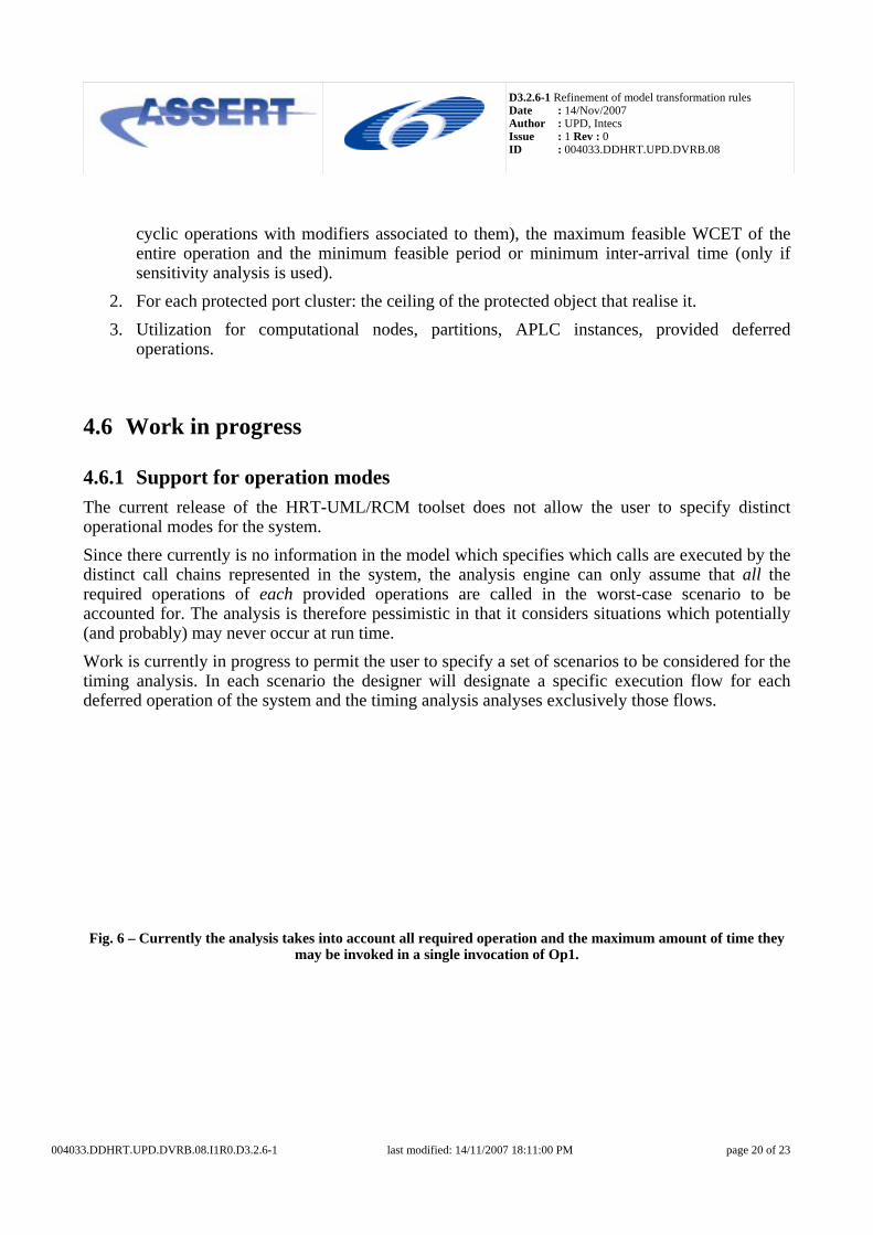
4.6.1 Support for operation modes The current release of the HRT-UML/RCM toolset does not allow the user to specify distinct operational modes for the system. Since there currently is no information in the model which specifies which calls are executed by the distinct call chains represented in the system, the analysis engine can only assume that all the required operations of each provided operations are called in the worst-case scenario to be accounted for. The analysis is therefore pessimistic in that it considers situations which potentially (and probably) may never occur at run time. Work is currently in progress to permit the user to specify a set of scenarios to be considered for the timing analysis. In each scenario the designer will designate a specific execution flow for each deferred operation of the system and the timing analysis analyses exclusively those flows.
Fig. 6 – Currently the analysis takes into account all required operation and the maximum amount of time they may be invoked in a single invocation of Op1.
004033.DDHRT.UPD.DVRB.08.I1R0.D3.2.6-1 last modified: 14/11/2007 18:11:00 PM page 20 of 23

D3.2.6-1 Refinement of model transformation rules Date : 14/Nov/2007 Author : UPD, Intecs Issue : 1 Rev : 0 ID : 004033.DDHRT.UPD.DVRB.08
Fig. 7 – The designer specifies a specific call chain that has to be analysed in a specific operational mode. Only Ri1 and Ri2 are analysed in the example.
4.6.2 Automated extraction of WCET estimates It may be overly difficult, time-consuming and error-prone for the user to decorate individual operations with their attributed WCET estimate in models of realistic size and complexity by hand, without the aid of some automation engine. To remedy this problem, the obvious enhancement to implement should permit to feed the decoration process with the output of a WCET analysis tool. Candidate tools for integration in the HRT-UML/RCM toolset include: Bound-T (developed by Tidorum, Finland, http://www.tidorum.fi/bound-t/) and RapiTime (developed by Rapita Systems, UK, http://www.rapitasystems.com/rapitime).
4.6.3 Complete modelling of the communication stack The communication stack embedded in the middleware layer of the ASSERT Virtual Machine comprises several threaded components whose behaviour has to be accurately accounted for in the timing feasibility analysis of the system model. To this end, the transformation process that turns the interface view into the concurrency view (which is the input to the timing feasibility analysis) should produce a faithful representation of the communication stack in terms of the VMLC elements that compose it. At the time this report is being written, only the PolyORB-HI tier is completely modelled. Work is in progress to include the modelling of the MTS/ SpaceWire driver tiers.
004033.DDHRT.UPD.DVRB.08.I1R0.D3.2.6-1 last modified: 14/11/2007 18:11:00 PM page 21 of 23

D3.2.6-1 Refinement of model transformation rules Date : 14/Nov/2007 Author : UPD, Intecs Issue : 1 Rev : 0 ID : 004033.DDHRT.UPD.DVRB.08
5 Feedback expected from the V3 demonstrators Important feedback and returns are expected from the development of the V3 demonstrators in different respects. From the methodological point of view, the issues of interest include:
• How does the designer like working with the different views that are currently available? Is their modelling well supported? Do they correspond to the user perspective of the problem? Are there any other suitable points of view that can be addressed and supported by the methodology?
• Is the separation between the functional and the non-functional views a useful means to foster the reusability of models?
From the toolset point of view, the issues of interest include:
• Is the tool prototype effective, easy to use, well documented? Did the user experience any model or diagram corruption?
• Is the diagram support for the different views effective?
• Is the integration with model transformations effective?
• Is the presentation of round-trip analysis results satisfactory for the user? In more detail, the following issues will be addressed with special care throughout the development of the V3 demonstrators, which is just starting at the time this report is being edited. Expressivity of HRT-UML/RCM HRT-UML/RCM provides the designer with comparatively vast expressive power, mainly by promoting a declarative specification for concurrent semantics, by taking care of stubs/skeletons via an automated model transformation and by providing a family of design/transformation patterns: the latter are particularly useful to give the designer the impression of not being too limited by Ravenscar constraints. It is however still necessary to investigate on how to provide PIM-level modelling for the state machine of the protocol agent (the OBCS in RCM jargon) Separation of concerns Even if HRT-UML/RCM promotes and pursues complete separation of concerns between the functional view and the concurrency view, sometimes such separation is impossible to achieve. For example, the callback pattern (which is used to realize deferred operations with out parameters in an asynchronous manner, to legally bypass the RCM restriction which prohibits synchronous communications by disallowing out parameters in deferred invocations) forces the functional designer to split the specification of a (logically single) method into two distinct operations. Several other similar examples exist. User feedback is therefore crucial to understand where the intended separation of concerns may or should be blurred for the greater benefit of the design model.
004033.DDHRT.UPD.DVRB.08.I1R0.D3.2.6-1 last modified: 14/11/2007 18:11:00 PM page 22 of 23
D3.2.6-1 Refinement of model transformation rules Date : 14/Nov/2007 Author : UPD, Intecs Issue : 1 Rev : 0 ID : 004033.DDHRT.UPD.DVRB.08
004033.DDHRT.UPD.DVRB.08.I1R0.D3.2.6-1 last modified: 14/11/2007 18:11:00 PM page 23 of 23
HRT-UML/RCM and AADL The current findings indicate that HRT-UML/RCM has proven to be superior to the current version of AADL for the modeling of the interface view and the functional view, mainly due to its higher-level semantics (including the support to Ravenscar-compliant design/transformation patterns) and support for object orientation; AADL however has proven superior in modeling hardware and hardware-software interactions. User feedback is important in this regard not so much to rank formalisms but rather to understand the designer needs and determine how they could be better addressed by each distinct formalism. Design process The design process promoted by HRT-UML/RCM leans toward bottom-up, starting from the functional contract behind the functional specification instead of top-down from system specification. The most evident limitation with that approach however presently appears to be caused by limitations with the modeling tools, in particular the contingent requirement that the functional view be fixed (non-mutable) before the design of the interface view may start. We postulate that, once modifications on the functional view may be mirrored on the interface view (for example by adding a provided interface if a new method is created), the bottom-up approach promoted by HRT-UML/RCM will match industrial needs. Needless to day, user feedback on this aspect is absolutely crucial to determine whether the direction taken in the very conception of HRT-UML/RCM is valid or needs rectifying. Quality of the developed tools The developed tools are not always as reliable as expected: this problem affects all aspects of the modeling/analysis process. The sheer size of the developed tools is such that it has become difficult to keep them synchronized and guarantee that their interaction is bug-free: the whole transformation chain (including round-trip) is extremely complex to handle and maintain; at the same time, some development tools (both ATL and MOFscript) sometimes include residual bugs. Since the V3 demonstrators aim at being realistic representations of real-life systems, user feedback on the perceived quality of the HRT-UML/RCM toolset will be a precious indicator of whether areas of it exist which need particular attention to robustness and reliability aspects.