D3.2 Aircraft aspects of the Endless Runway · D3.2 Aircraft aspects of the Endless Runway. This...
89
D3.2 Aircraft aspects of the Endless Runway This document details the studies that have been made in order to identify the most promising runway cross-section and to design a future aircraft concept tailored for operations on a circular runway. Project Number 308292 Document Identification D3.2_Aircraft_Aspects Status Final Version 1.0 Date of Issue 30-09-2013 Authors Schmollgruber P.; De Giuseppe A.; Dupeyrat M.; Organisation ONERA Classification Public
Transcript of D3.2 Aircraft aspects of the Endless Runway · D3.2 Aircraft aspects of the Endless Runway. This...

D3.2 Aircraft aspects of the Endless Runway
This document details the studies that have been made in order to identify the most promising runway cross-section and to design a future aircraft concept tailored for operations on a circular runway.
Project Number 308292 Document Identification D3.2_Aircraft_Aspects Status Final Version 1.0 Date of Issue 30-09-2013
Authors Schmollgruber P.; De Giuseppe A.; Dupeyrat M.;
Organisation ONERA
Classification Public

EC DG-RTD
Contract: ACP2-GA-2012-308292- ENDLESS RUNWAY
Ref.: D3.2_Aircraft_Aspects
Status: Final version 1.0 Date: 30-09-2013 Page 2/89
Public
The Endless Runway D3.2_Aircraft_Aspects
Document Change Log Versio
Author Date Affected Sections Description of Change
0.1 P. Schmollgruber 7/02/2013 All Initiation of the document structure
0.2 P. Schmollgruber
A. De Giuseppe
24/08/2013 All Methodology and results of the various simulations described.
0.3 M. Dupeyrat 26/08/2013 All Review and addition of the chapters regarding the ground clearance of the aircraft elements and runway volume calculation.
0.4 S. Aubry All Review
0.5 J. Hermetz All Review
1.0 P. Schmollgruber 30/09/2013 All Release version
Document Distribution Organisation Name
EC Ivan Konaktchiev
NLR Henk Hesselink, René Verbeek, Carl Welman, Joyce Nibourg
DLR Steffen Loth, Franz Knabe, Sandro Lorenz, Paul Weitz
ONERA Maud Dupeyrat, Sébastien Aubry, Peter Schmollgruber
INTA Francisco Mugnoz Sanz, María Vega Ramírez, Albert Remiro
ILOT Marián Jez
Review and Approval of the Document Organisation Responsible for Review Reference of comment documents Date
All 1.0 30-09-2013
Organisation Responsible for Approval Name of person approving the document Date
NLR H. Hesselink 30-09-2013

EC DG-RTD
Contract: ACP2-GA-2012-308292- ENDLESS RUNWAY
Ref.: D3.2_Aircraft_Aspects
Status: Final version 1.0 Date: 30-09-2013 Page 3/89
Public
The Endless Runway D3.2_Aircraft_Aspects
Table of Contents
Document Change Log 2 Document Distribution 2 Review and Approval of the Document 2 Abbreviations 5
Introduction 7 1.
Simulation environment 8 2.
2.1 Simulation environment selection 9 2.2 General use of Flight Gear in WP3 10
Feasibility of a conventional configuration 12 3.
3.1 Approach 12 3.2 Reference aircraft selection 12 3.3 Definition of the B747-100 model 13 3.3.1 Aircraft 3D model 14 3.3.2 Aircraft characteristics 14 3.3.3 Engine model 18 3.4 Validation of the B747-100 model 18 3.4.1 Take-off performance 18 3.4.2 Calibration of the landing performance 20 3.5 Parametric studies 21 3.5.1 Runway shape definition 21 3.5.2 Runway volume calculation 24 3.5.3 Take-off simulations 25 3.5.4 Performance analysis 26 3.5.4.1 Definition of the take-off and landing distances 26 3.5.4.2 Linear speed distribution 27 3.5.4.3 Square root speed distribution 31 3.5.4.4 Square speed distribution 34 3.5.5 Assessment 34 3.5.5.1 Square root speed vs. linear speed distribution for a reference width of 140 meters 35 3.5.5.2 Selection of the reference width 36 3.5.6 Landings 37 3.5.7 B747-100 ground clearance analysis 40

EC DG-RTD
Contract: ACP2-GA-2012-308292- ENDLESS RUNWAY
Ref.: D3.2_Aircraft_Aspects
Status: Final version 1.0 Date: 30-09-2013 Page 4/89
Public
The Endless Runway D3.2_Aircraft_Aspects
3.6 Conclusions on exchange parameters 41
New aircraft tailored for the Endless Runway 43 4.
4.1 Approach 43 4.2 ERAC Conceptual Design 43 4.2.1 Mission definition 43 4.2.2 Preliminary requirement analysis 44 4.2.3 ERAC Concepts exploration 44 4.2.4 ERAC sizing 49 4.2.4.1 Sizing process 49 4.2.4.2 Engine selection 51 4.2.4.3 ERAC geometry 53 4.2.4.4 ERAC weight breakdown 53 4.2.4.5 Final ERAC sketch 54 4.2.5 ERAC ground clearance analysis 56 4.3 ERAC model for Flight Gear 57 4.3.1 Inertial properties 57 4.3.2 Refined aerodynamics study 58 4.3.2.1 Lift-to-drag ratio verification 58 4.3.2.2 Complementary aerodynamics coefficients for Flight Gear 60 4.3.3 3D model 63 4.4 ERAC simulations 64 4.5 ERAC performance analysis 65 4.5.1 Take-off 65 4.5.2 Landing 68 4.6 Requirements review 71 4.7 Conclusion on exchange parameters 72
Conclusion 74 5.
5.1 Aircraft aspects for the Endless Runway 74 5.2 Perspective 75
References 77 6.
Appendix A Key parameters of the Endless Runway project 78
Appendix B Detail of the calculations 79
Appendix B.1 Calculation of the various runway profiles equations 79 Appendix B.2 Calculation of the runway volume for the linear speed evolution runway profile 81 Appendix B.3 Ground clearance of aircraft critical elements with the Endless Runway 82

EC DG-RTD
Contract: ACP2-GA-2012-308292- ENDLESS RUNWAY
Ref.: D3.2_Aircraft_Aspects
Status: Final version 1.0 Date: 30-09-2013 Page 5/89
Public
The Endless Runway D3.2_Aircraft_Aspects
Abbreviations Acronym Definition
α Angle of attack
δa Aileron deflection
δe Elevator deflection
δr Rudder deflection
ATM Air Traffic Management
CDERAC Total drag coefficient of ERAC
CDi Induced Drag Coefficient
CD0 Zero-lift drag Coefficient
Cl Rolling moment Coefficient
CL Lift Coefficient
CL0 Lift Coefficient at zero angle of attack
Cm Pitching moment Coefficient
Cn Yawing moment Coefficient
CY Side-force Coefficient
∆CLFlap Changes in Lift Coefficient due to Flap
DLR Deutsches Zentrum für Luft- und Raumfahrt
EIS Entry Into Service
ER Endless Runway
ERAC Endless Runway Aircraft Concept
FAR Federal Aviation Regulation
ft feet
ILOT Institute of Aviation
INTA Instituto Nacional de Técnica Aeroespacial
Ixx Moment of Inertia around the X axis
ISA International Standard Atmosphere
kts Knots

EC DG-RTD
Contract: ACP2-GA-2012-308292- ENDLESS RUNWAY
Ref.: D3.2_Aircraft_Aspects
Status: Final version 1.0 Date: 30-09-2013 Page 6/89
Public
The Endless Runway D3.2_Aircraft_Aspects
LDL Landing Length
m meter
MIT Massachusetts Institute of Technology
MLW Maximum Landing Weight
MTOW Maximum Take-Off Weight
NLR National Aerospace Laboratory of the Netherlands
OEI One Engine Inoperative
Onera The French Aerospace Lab
p Roll rate
q Pitch rate
r Yaw rate
s second
T/W Thrust-to-Weight ratio
TSFC Thrust Specific Fuel Consumption
VLO Lift-off speed
VR Rotation speed
W/S Wing loading [kg/m²]

EC DG-RTD
Contract: ACP2-GA-2012-308292- ENDLESS RUNWAY
Ref.: D3.2_Aircraft_Aspects
Status: Final version 1.0 Date: 30-09-2013 Page 7/89
Public
The Endless Runway D3.2_Aircraft_Aspects
Introduction 1.According to various publications proposing vision statements for air transportation [1][2], the global traffic could reach 16 billion passengers annually in 2050 leading thus to “congestion of infrastructure”. It is then mandatory for research institutes today to explore innovative airport concepts that present a certain discontinuity in order to achieve a significant step forwards in terms of capacity performance. Today’s solutions that have been optimized for decades have indeed only small margins for improvement left.
With this objective, the Endless Runway consortium (NLR, DLR, ILOT, INTA, Onera) proposes to investigate a radical solution for airport layouts based on a circular banked runway. The key asset is to offer the possibility to take-off and land in any direction from any point on the circle. In addition, since the airport facilities would be located inside the circle, the expensive land covered by the entire airport would be reduced.
Such a global concept not only requires to redesign the complete airport layout but also to analyze in details the air traffic management (ATM) aspects. However, regarding operations on this Endless Runway, it must be noted that an aircraft will move to the outside of the circle during the take-off acceleration because of the centrifugal force. To limit its effects on the aircraft structure and passengers, the runway will be banked. Therefore, at lift-off, the aircraft will be operating in a specific position on the runway with a certain bank angle at a given height. For landing, the aircraft will touchdown in a specific point, with a given speed and a specific bank angle. As the velocity decreases, the airplane will move towards the center of the runway where the bank angle tends to be null. These unconventional maneuvers for take-off and landing require to complete a study (WP3) focusing on aircraft design aspects that will use the Endless Runway.
Preliminary discussions within the consortium identified five decisive requirements that shall be achieved during the investigations related to the aircraft aspects of the Endless Runway:
• To indicate whether it is possible for a 2010 civil transport aircraft to take-off and land on a circular runway;
• To investigate the required changes on a conventional aircraft to use the Endless Runway concept; • To calculate the take-off and landing performance of the aircraft; • To identify the best suited new configuration for taking-off and landing from a circular runway; • To compare the take-off and landing performances of this unconventional aircraft to the ones of a
standard aircraft.
The completed work will allow the determination of the exchanges parameters (Appendix A) that are necessary for an assessment of the Endless Runway from an airport and ATM point of view.
Regarding the level of details needed to take-off and land from an Endless Runway, it is necessary to set-up a complete design and simulation environment. Thus, the first technical section of this report presents such an environment that is based on the free and open-source program Flight Gear. Subsequently, the document details all the work that has been performed to assess the feasibility to take-off and land from a circular runway with an existing aircraft (task T3.1 in the project). Additional information is provided in order to explain the rationale behind the selection of the runway cross section as well as its reference width. Finally, this report details the activities that have been performed in order to design and simulate in Flight Gear an innovative aircraft concept that is tailored to the Endless Runway (task T3.2 in the project).

EC DG-RTD
Contract: ACP2-GA-2012-308292- ENDLESS RUNWAY
Ref.: D3.2_Aircraft_Aspects
Status: Final version 1.0 Date: 30-09-2013 Page 8/89
Public
The Endless Runway D3.2_Aircraft_Aspects
Simulation environment 2.When looking at the decisive requirements as stated in the introduction, emphasis is given to the performance calculation of today’s and tomorrow’s aircraft on a circular runway. In aircraft design, the general approach to determine the take-off and landing performance is to make a two-dimension analysis of the aircraft considered as a point mass where different forces are applied: lift, drag, thrust, ground reactions. An example of this approach well suited for classical operations on a flat runway is illustrated in the following figure.
Figure 1 : Classical performance analysis for take-off [3]
By solving the equations along the X axis, it is then possible to find an analytical solution corresponding to the take-off field length. The method is quick, reliable and it allows taking into account a certain slope of the runway as well as a wind component. However, in the case of the Endless Runway concept, the runway is asymmetric and curved. The take-off and landing phases must then be analyzed in three-dimensions and a numerical method will be required to solve the equations of motion.
Another decisive requirement for WP3 stresses the necessity to be able to assess the capability of a current aircraft to take off and land on a circular runway. In this case, a full analysis of the aircraft motion is required and the system to be solved takes into account the three degrees of freedom along (forces) and the three degrees of freedom around (moments) the reference axes and the various associated variables. The figure here below illustrates the different variables to be considered.
Figure 2 : Variables to be considered to assess the aircraft motion (ground reactions are not shown) [4]

EC DG-RTD
Contract: ACP2-GA-2012-308292- ENDLESS RUNWAY
Ref.: D3.2_Aircraft_Aspects
Status: Final version 1.0 Date: 30-09-2013 Page 9/89
Public
The Endless Runway D3.2_Aircraft_Aspects
The two previous points indicate that in order to analyze the aircraft behavior during take-off and landing and to calculate its take-off and landing performance on a banked runway, a 6 degrees-of-freedom (DOF) simulator will be mandatory.
There are several 6DOF simulators available (commercial and free) and all aeronautical research centers developed their own propreterian codes over the years. However, the simulator to be used in the Endless Runway project for WP3 has to meet a number of specific requirements:
1. It must be flexible enough to enable take-offs and landings from circular runways with different bank angles;
2. It must be flexible enough to enable simulations with new aircraft concepts; 3. It must be shared by the different partners; 4. It must be open to modifications by all partners; 5. It must be as reliable as possible.
2.1 Simulation environment selection With the basic requirements of the simulator fixed, a review of the possible options has been carried out. The problem with most of commercial software is their limited flexibility. It is indeed difficult to implement in the simulation a new aircraft with its characteristics as well as a new type of three dimensional runway. However, among these products, X-Plane [5] enables users to build airplanes through the program “Plane-maker” and it offers also the possibility to design sceneries. Regarding free software, partners all agree that Flight Gear [6] is the key reference in the domain of 6DOF simulations. An important asset for Flight Gear is its large community of contributors since it is a free software. The continuous improvements made over the years resulted in a reliable product. Another reason for its success is its flexibility: Flight Gear offers the possibility to use its different modules independently, to select different flight dynamics models and their associated aircraft characteristics, to add new vehicles and airports layouts. Some 6DOF simulators offer 3D visualizations. They are generally developed in C++ or with Matlab and their outputs are plots of different variables over time. All Endless Runway partners have developed such simulators over the years that could be used (with some modifications) in the project. However, since the software has to be shared and modified by the different contributors, there are complicated intellectual properties issues. There is then the option to develop from scratch such a code that would be tailored to the need of the required analyses.
Since there are requirements stipulating that the simulator must be shared and can be modified by all partners, it cannot be affected by proprietary aspects. Regarding commercial software, X-Plane seems to be a good choice given its low price and the positive feedback about its reliability. Flight Gear on the other hand is completely free. In addition, its architecture makes it easy to implement new aircraft and new runway shape with their associated files containing all characteristics. In the end, the remaining two options for the simulation environment are:
• An especially developed 6-degrees-of-freedom model tailored on the project requirements; • Flight Gear (no cost at all with respect to X-Plane).
The subsequent qualitative assessment between these two solutions is presented in the following table that summarizes pros and cons of both solutions.

EC DG-RTD
Contract: ACP2-GA-2012-308292- ENDLESS RUNWAY
Ref.: D3.2_Aircraft_Aspects
Status: Final version 1.0 Date: 30-09-2013 Page 10/89
Public
The Endless Runway D3.2_Aircraft_Aspects
Table 1: Assets and drawbacks of the possible simulation environments
Tailored 6DOF simulator Flight Gear
Assets
• Complete knowledge of the physics behind the simulation
• Possibility to modify the code in case of a specific issue
• Possibility to run completely automated take-off and landing segments
• Proven simulation software based on a 6 DOF model
• It is a full simulation tool enabling any user to fly the aircraft
• A large community developed auxiliary tools to develop the scenery
• Possibility to model new aircraft concepts • Source code available • Good visualization possibilities
Drawbacks
• Significant development time • Outputs would be plots • Difficulty in the modelling of the
circular runway • Difficulty to organize the work
between the partners
• Changes to the original code are risky • Physics needs to be validated before use • Simulations might require manual inputs
decreasing thus the repeatability
After weighting all the different options, the WP team decided to use Flight Gear as the simulation environment for the activities of WP3. This choice is consolidated by the fact that this program is widely used in research for simulation developments [7]. However, the associated drawbacks must be taken into account. Therefore, to verify the physics laws implemented in Flight Gear, there is a task in WP3 that is solely dedicated to validate the reference aircraft model.
2.2 General use of Flight Gear in WP3 The goal of this section is to quickly present the structure of Flight Gear and how this simulator will be used in WP3. First, it is important to know that the overall simulation relies on a Flight Dynamics Model (FDM). This is the module that takes into account all pilots inputs, ground reactions during take-off and landing, aircraft properties (aerodynamics, weights, inertia, propulsion…) and determines the behavior of the airplane over time. The aircraft characteristics are stored in .xml files where the FDM will look for specific values. There is then the visualization part: 3D models in the .ac format [8] are integrated in the virtual environment and the user can see its aircraft flying over the newly created airport.
For the scope of aircraft studies in the Endless Runway project, the selected Flight Dynamics model is JSBSim [9]. Through this selection, the partners have complete control of the inputs that are transferred to the simulator: JSBSim relies indeed on all the aircraft characteristics that are indicated by the designers in the .xml file. Then, 3D models of both the aircraft and the banked circular runway are integrated in the simulator. At this point, it is possible to manually fly the mission and to assess in a qualitative manner the behavior of the aircraft on the Endless Runway concept. However, the decisive requirements stated in the introduction require a quantitative approach. In order to enable a more refined analysis, the recording of all aircraft parameters during the mission is activated. In this manner, Flight Gear generates a .txt file (called telemetry.txt in the project) that collects all necessary aircraft parameters. Following the approach taken during flight test analyses, the take-off and landing performances are calculated based on the recorded values provided by the simulator. In this first assessment of the aircraft behavior on a circular runway, the simulations are made without the effects of wind. The Flight Gear set-up used in WP3 is illustrated in the following figure:

EC DG-RTD
Contract: ACP2-GA-2012-308292- ENDLESS RUNWAY
Ref.: D3.2_Aircraft_Aspects
Status: Final version 1.0 Date: 30-09-2013 Page 11/89
Public
The Endless Runway D3.2_Aircraft_Aspects
Figure 3 : Flight Gear set-up for WP3
Flight Dynamics Model : JSBSim
.XML file
Pilot inputs
Computer Screen
Airport 3D model
Aircraft 3D model
Flight Gear Virtual Mission
Telemetry.txt

EC DG-RTD
Contract: ACP2-GA-2012-308292- ENDLESS RUNWAY
Ref.: D3.2_Aircraft_Aspects
Status: Final version 1.0 Date: 30-09-2013 Page 12/89
Public
The Endless Runway D3.2_Aircraft_Aspects
Feasibility of a conventional configuration 3.
3.1 Approach The work presented in this chapter corresponds to the activities performed within Task 3.1 “Feasibility of a conventional configuration”. The objective is to take an existing passenger aircraft and to operate it on an Endless Runway airport to both assess its behavior and define the attainable level of performance. From a practical point of view, the work is divided in two parts. The first one consists in modeling a reference aircraft and validating its take-off and landing performances on a classical dry runway. This stage is mandatory in order to minimize the uncertainty regarding the physics used in the simulator as explained in the previous chapter. The second step focuses on simulations with different banked circular runways. The outcome of these tests is a direct comparison of the aircraft behavior on these different tracks, the determination of the level of take-off and landing performances and the identification of the most promising runway cross section. The approach that has been used in the final part of T3.1 is illustrated here below:
Figure 4 : Approach to be used in the final part of T3.1
3.2 Reference aircraft selection In such a prospective study, it is important to select the correct reference or baseline in order to draw conclusions on the investigated system. Usually, in aircraft studies, single aisle aircraft (Boeing 787 or Airbus A320) are usually taken as references since they are a key market segment [10][11]. However, in the case on the Endless Runway project, the object under study is the runway and the reference aircraft provides only metrics for the assessment. With the objective of remaining conservative, the baseline aircraft must then correspond to the most challenging case for the design of the Endless Runway. Because of the banking of the runway, it is clear that large wingspans aircraft (and especially with wings in the lower position) may have ground contact issues. This problem is emphasized if engines are located under the wing. These different elements lead to the selection of a 4 engines low-wing twin-aisle aircraft as reference: it would indeed have a large wing area because of the high weight and a lower ground clearance between the track and the outer engines. At this stage, the WP3 Team identified 3 possibilities:
• The Airbus A340 • The Airbus A380 • The Boeing B747
Flight Dynamics Model : JSBSim
validated.XML file
Pilot inputs
Computer Screen
3D parametric shapes
Flight Gear Virtual Mission
Telemetry.txt
Reference Aircraft3D model
Post Flight Analysis
Performance analysis
Runway cross section selection
0
5
10
15
20
25
30
35
40
45
50
0 20 40 60 80 100 120 140
y
x
EC DG-RTD
Contract: ACP2-GA-2012-308292- ENDLESS RUNWAY
Ref.: D3.2_Aircraft_Aspects
Status: Final version 1.0 Date: 30-09-2013 Page 13/89
Public
The Endless Runway D3.2_Aircraft_Aspects
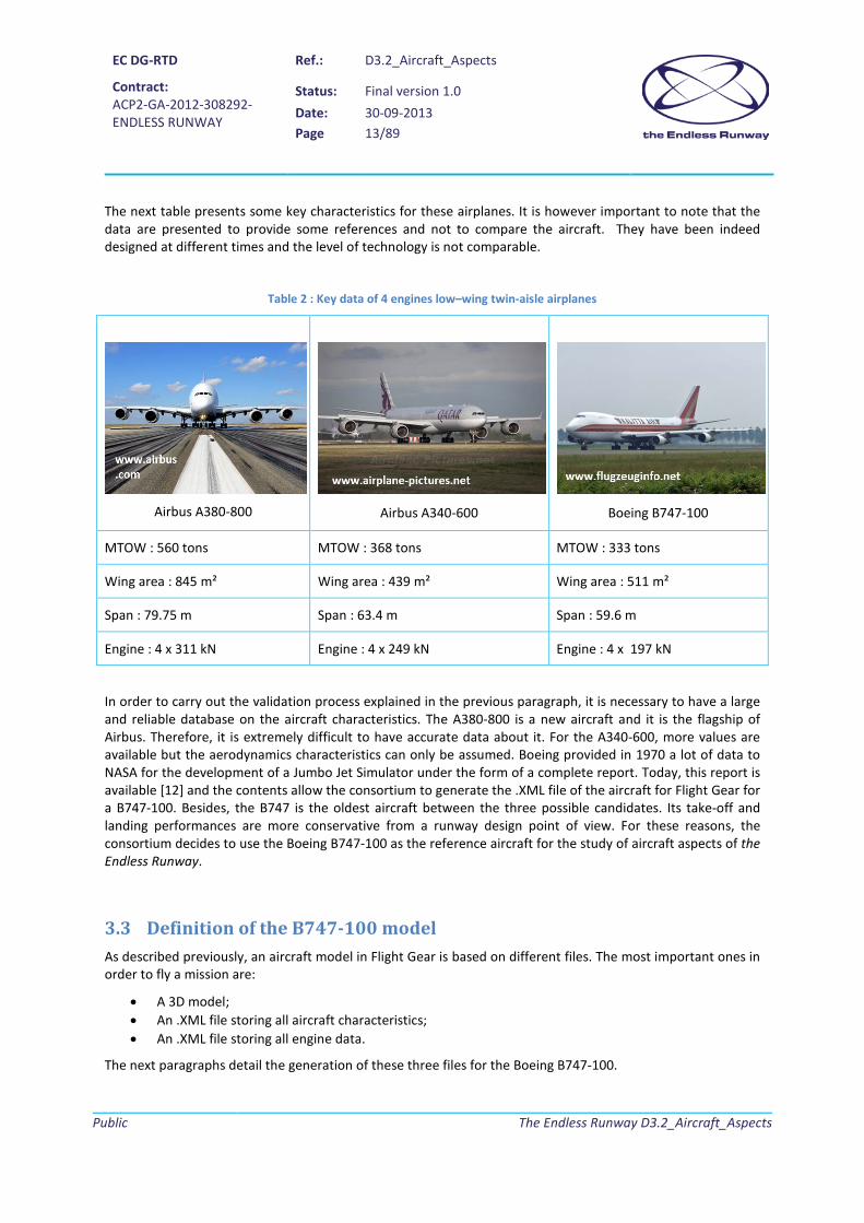
The next table presents some key characteristics for these airplanes. It is however important to note that the data are presented to provide some references and not to compare the aircraft. They have been indeed designed at different times and the level of technology is not comparable.
Table 2 : Key data of 4 engines low–wing twin-aisle airplanes
Airbus A380-800
Airbus A340-600
Boeing B747-100
MTOW : 560 tons MTOW : 368 tons MTOW : 333 tons
Wing area : 845 m² Wing area : 439 m² Wing area : 511 m²
Span : 79.75 m Span : 63.4 m Span : 59.6 m
Engine : 4 x 311 kN Engine : 4 x 249 kN Engine : 4 x 197 kN
In order to carry out the validation process explained in the previous paragraph, it is necessary to have a large and reliable database on the aircraft characteristics. The A380-800 is a new aircraft and it is the flagship of Airbus. Therefore, it is extremely difficult to have accurate data about it. For the A340-600, more values are available but the aerodynamics characteristics can only be assumed. Boeing provided in 1970 a lot of data to NASA for the development of a Jumbo Jet Simulator under the form of a complete report. Today, this report is available [12] and the contents allow the consortium to generate the .XML file of the aircraft for Flight Gear for a B747-100. Besides, the B747 is the oldest aircraft between the three possible candidates. Its take-off and landing performances are more conservative from a runway design point of view. For these reasons, the consortium decides to use the Boeing B747-100 as the reference aircraft for the study of aircraft aspects of the Endless Runway.
3.3 Definition of the B747-100 model As described previously, an aircraft model in Flight Gear is based on different files. The most important ones in order to fly a mission are:
• A 3D model; • An .XML file storing all aircraft characteristics; • An .XML file storing all engine data.
The next paragraphs detail the generation of these three files for the Boeing B747-100.

EC DG-RTD
Contract: ACP2-GA-2012-308292- ENDLESS RUNWAY
Ref.: D3.2_Aircraft_Aspects
Status: Final version 1.0 Date: 30-09-2013 Page 14/89
Public
The Endless Runway D3.2_Aircraft_Aspects
3.3.1 Aircraft 3D model
One of the key inputs for the simulation visualization is the 3D model of the aircraft. The Flight Gear community developed over the years numerous 3D aircraft models that can be downloaded and used in the simulations. After a review of different digital-mock-ups associated to the Boeing B747-100, the partners identified an accurate 3D model available in [6] and illustrated in the next figure as an option to be used in the Endless Runway project. The model has indeed a lot of details such as high-lift devices and landing gears.
Figure 5 : 3D model of the B747-100
In order to validate this model, some verification must be made. The partners have therfore compared various lengths on the 3D model with reference data that are measured on the three-view drawing provided by Boeing [13]. Since no major deviation has been noted, the selected 3D model is used in the project for the planned activities.
3.3.2 Aircraft characteristics
To feed the Flight Dynamics Model (JSBSim in this case), all aircraft characteristics are stored in an .xml file whose name is the aircraft name. The next figure shows the highest level of the file where all systems and disciplines are listed:

EC DG-RTD
Contract: ACP2-GA-2012-308292- ENDLESS RUNWAY
Ref.: D3.2_Aircraft_Aspects
Status: Final version 1.0 Date: 30-09-2013 Page 15/89
Public
The Endless Runway D3.2_Aircraft_Aspects
Figure 6 : Highest level of the B747 description file (747-100.xml)
Values available in the reference report [12] and data provided by Boeing [13] allow the completion of both the “metrics” section (storage of geometrical reference lengths) and the “mass_balance” section (storage of weight and inertial data) in the .xml file:
Figure 7 : How inertia data are provided to JSBSim in the .xml file
It must be noted that the inertia data (moments of inertia and products of inertia) are in this case fixed. One file describes the B747-100 characteristics in the take-off configuration and a second one provides characteristics for landing. The changes are clearly not negligible (Ixx, the body axis moment of inertia varies from 14e+06 to 19e+6 slug.ft² at MTOW).
For ground reactions, landing gear position entered in the .xml file correspond to the values presented in [12] and the rolling friction coefficient is fixed to the average value for a dry concrete surface. Regarding the parameters of the landing gear, the values found in the original .xml file are kept. Moreover, with the objective of checking the possible contacts between the aircraft and the banked runway during the take-off and landing phases, it has been decided to add contact points (23) on the critical area of the aircraft. The contact points are defined by their geometrical location (X, Y, Z coordinates) and very high values for both the static and dynamic friction coefficient. This non-physical value generates such a high friction force that the aircraft cannot move

EC DG-RTD
Contract: ACP2-GA-2012-308292- ENDLESS RUNWAY
Ref.: D3.2_Aircraft_Aspects
Status: Final version 1.0 Date: 30-09-2013 Page 16/89
Public
The Endless Runway D3.2_Aircraft_Aspects
anymore. In this manner, if one of these critical points ends up touching the 3D model of the circular track, the simulation is stopped. The user understands then that the cause is a ground contact.
Figure 8 : Ground reaction data
For the propulsion system, the high level .xml file calls another file where the performances of the engine are described (see section 3.3.3) and provides the location of the 4 engines.
To complete the necessary data for the Flight Dynamic Model, the B747-100 aerodynamics must be implemented. Based on curves provided in [12], ONERA generated the lookup table requested by JSBSim. The next figures illustrate the reference curves for the lift coefficient (for different flap settings) and how the data are entered in the .xml file.

EC DG-RTD
Contract: ACP2-GA-2012-308292- ENDLESS RUNWAY
Ref.: D3.2_Aircraft_Aspects
Status: Final version 1.0 Date: 30-09-2013 Page 17/89
Public
The Endless Runway D3.2_Aircraft_Aspects
Figure 9 : Lift coefficient data for the B747-100 [12]
Figure 10 : Lift coefficient lookup table used in Flight Gear
The same procedure is repeated for the other two force coefficients (drag and side-force) and the three moment coefficients (roll, pitch and yaw).

EC DG-RTD
Contract: ACP2-GA-2012-308292- ENDLESS RUNWAY
Ref.: D3.2_Aircraft_Aspects
Status: Final version 1.0 Date: 30-09-2013 Page 18/89
Public
The Endless Runway D3.2_Aircraft_Aspects
3.3.3 Engine model
The engine data are stored in a specific .xml file that has the name of the engine installed on the aircraft. For the B747-100 mode, a file called JTD9D.xml is available. In order to model the engine performance with respect to flight altitude and Mach, the WP3 Team uses the formulas proposed in E. Roux’ PhD [14]. Part of her work focused on the development of an analytical engine model suited for conceptual design studies. With respect to other models, her approach took into account physical aspects to have more reliable results.
In [15], the characteristics of the JT9D-3A are given:
• Static Thrust : 196833 N • By-Pass ratio : 5.2 • Overall Pressure Ratio : 21.5
Based on these values, the evolution of the installed thrust for each engine as a function of Mach and altitude has been determined. The figure below details the evolution of the installed maximum thrust for the JT9D-3A engine at the take-off.
Figure 11 : JT9D-3A installed thrust at take-off
3.4 Validation of the B747-100 model With the B747-100 model completed, the next step is to compare the take-off distance (all engines operative) obtained through Flight Gear simulations and reference values provided in [12].
3.4.1 Take-off performance
The take-off distance is defined as the distance covered by the aircraft from where the brake-release point to the altitude of 35 ft. Between these two points, the aircraft reaches various speeds related to the certification.

EC DG-RTD
Contract: ACP2-GA-2012-308292- ENDLESS RUNWAY
Ref.: D3.2_Aircraft_Aspects
Status: Final version 1.0 Date: 30-09-2013 Page 19/89
Public
The Endless Runway D3.2_Aircraft_Aspects
At VR, the rotation speed, the pilot provides an input to initiate the rotation. At VLO, the aircraft becomes airborne. The distance from the starting point up to VLO is called the ground run. Figure 12 illustrates this critical phase of the mission.
Figure 12 : Illustration of the take-off distance (modified picture from [3])
In the Boeing report [12], experimental data of a ground run up to lift-off speed are provided. Since it is difficult to repeat in Flight Gear the same rotation input as in [12], the consortium decided to compare the experimental data to the simulation value up to VR. The next figures show that the simulation is capable of reproducing the real behavior of the aircraft with only limited error margin.
Figure 13 : Speed behavior during the ground run
H=35 ft
Take-off distance

EC DG-RTD
Contract: ACP2-GA-2012-308292- ENDLESS RUNWAY
Ref.: D3.2_Aircraft_Aspects
Status: Final version 1.0 Date: 30-09-2013 Page 20/89
Public
The Endless Runway D3.2_Aircraft_Aspects
Figure 14 : Behavior of the model concerning the ground distance
These results validate the correct behavior of the B747-100 model in Flight Gear for the take-off phase.
3.4.2 Calibration of the landing performance
For the landing phase, the validation cannot be performed. In the case of the B747-100, there are no clear indications in the available documents about the braking procedures. It has been thus decided to use the FAR (Federal Aviation Regulation) Landing Length presented in [12] to calibrate the static friction coefficient in the B747-100.xml file used for landing simulations as indicated in Figure 15.
Figure 15 : FAR Landing length for the B747-100 [12]

EC DG-RTD
Contract: ACP2-GA-2012-308292- ENDLESS RUNWAY
Ref.: D3.2_Aircraft_Aspects
Status: Final version 1.0 Date: 30-09-2013 Page 21/89
Public
The Endless Runway D3.2_Aircraft_Aspects
From the previous figure, it can be observed that the B747-100 lands in about 1950 m in its maximum landing weight configuration. After several simulations, the team decided to fix the static friction coefficient to 0.2. This coefficient has been chosen in order to obtain the FAR landing distance with full-brakes activated for the entire ground run.
3.5 Parametric studies The following parametric studies based on simulations aim at identifying the most promising cross section of the runway considering various aspects including take-off performance and subsequently the best width. Landings are tested next on the best shape considering the most advantageous width.
3.5.1 Runway shape definition
Following the preliminary review of circular runway activities in [16], the consortium decided to compare three runway cross-sections. These sections are classified according to the speed variation they provide along the circle radius (x):
• Linear speed distribution 𝑉 = 𝐾. 𝑥
• Square speed distribution 𝑉 = 𝐾. 𝑥2
• Root square speed distribution 𝑉 = 𝐾.√𝑥
As expressed in [17], the shape of the runway is defined by the following equation (with R0 the radius of the inner circle, x the radial position and z the runway height):
𝑧 =1
𝑔.𝑅0�
𝑉2
�1 + 𝑥𝑅0�
𝑥
0𝑑𝑥
It is then possible to mathematically calculate the runway height depending on the position along the circle radius (see Appendix B.1 for calculation detail):
• For a linear speed distribution, the height is defined as:
𝑧 =𝐾2𝑅02
𝑔�12𝑋2
𝑅02−𝑋𝑅0
+ ln �1 +𝑋𝑅0�� , with 𝐾 =
𝑉𝑚𝑟𝑥𝑊𝑟𝑟𝑟𝑟𝑟𝑟
• For a square speed distribution, the height is defined as:

EC DG-RTD
Contract: ACP2-GA-2012-308292- ENDLESS RUNWAY
Ref.: D3.2_Aircraft_Aspects
Status: Final version 1.0 Date: 30-09-2013 Page 22/89
Public
The Endless Runway D3.2_Aircraft_Aspects
𝑧 =𝐾2𝑅03
𝑔�𝑋4
4𝑅03−𝑋3
3𝑅02+𝑋2
2𝑅0− 𝑋 + 𝑅0 ln �1 +
𝑋𝑅0�� , with 𝐾 =
𝑉𝑚𝑟𝑥𝑊𝑟𝑟𝑟𝑟𝑟𝑟
2
• For a square root speed distribution, the height is defined as:
𝑧 =𝐾2
𝑔�𝑋 − 𝑅0 ln �1 +
𝑋𝑅0�� , with 𝐾 =
𝑉𝑚𝑟𝑥�𝑊𝑟𝑟𝑟𝑟𝑟𝑟
The first parametric study consists in fixing the reference width to 140 meters and applying the different formulas to calculate the correct cross section. During simulations with the B747-100 on straight runways, the rotation speed was fixed to 160 kts. In order to have a certain security margin, the maximum speed to be achieved on the banked runway is set at 200 kts (102.9 m/s). Knowing that the inner radius of the circular runway is equal to 1500 m and that the speed of 102.9 m/s is reached at a width of 140 m, it is possible to draw the complete runway cross section. The figure below shows the different speed distribution and the corresponding shapes.

EC DG-RTD
Contract: ACP2-GA-2012-308292- ENDLESS RUNWAY
Ref.: D3.2_Aircraft_Aspects
Status: Final version 1.0 Date: 30-09-2013 Page 23/89
Public
The Endless Runway D3.2_Aircraft_Aspects
Figure 16 : Speed distributions and associated runway profiles
With these curves, each runway cross section has been modeled with AC3D. The next figures illustrate the 3D model of a circular runway based on the linear speed distribution:
Figure 17 : 3D model of the circular runway (linear speed variation – width = 140m)

EC DG-RTD
Contract: ACP2-GA-2012-308292- ENDLESS RUNWAY
Ref.: D3.2_Aircraft_Aspects
Status: Final version 1.0 Date: 30-09-2013 Page 24/89
Public
The Endless Runway D3.2_Aircraft_Aspects
3.5.2 Runway volume calculation
In order to provide additional information for the multi-criteria analysis, it is decided to estimate the required volume of ballast that would be necessary build the banked circular runway. The next figure illustrates the parameters that are used to complete this preliminary calculation:
Figure 18 - Parameters used for the computation of the runway volume
Guldin second theorem tells us that the volume of the runway section is the product of the area A of the section between f(x) and z=0 by the length of the circle covered by its center of gravity, G, of abscises xG.
𝑉 = 2𝜋𝑥𝐺𝐴
The following formula ([33]) gives the abscissa of the center of mass:
𝑥𝐺 =1𝐴� 𝑥𝑓(𝑥)𝑑𝑥𝑅0′
𝑅0
The two previous equations combined imply:
𝑉 = 2𝜋 �1𝐴� 𝑥𝑓(𝑥)𝑑𝑥 𝑅0′
0� 𝐴
And finally:
V = 2π� xf(x)dx R0′
R0
The generic formula expressed above is now specifically applied to the “linear speed” runway profile.
In the 2D plan (O, x, z), the runway section profile is defined by F, translation of f(x) of which origin is moved at the center of the circular runway:
O
z
x R0 R’0
f(x)
𝑅0′ = 𝑅0 + 𝑊𝑟𝑟𝑟𝑟𝑟𝑟
xcg
Area A

EC DG-RTD
Contract: ACP2-GA-2012-308292- ENDLESS RUNWAY
Ref.: D3.2_Aircraft_Aspects
Status: Final version 1.0 Date: 30-09-2013 Page 25/89
Public
The Endless Runway D3.2_Aircraft_Aspects
𝐹(𝑥) = �0, 𝑥 < 𝑅0
𝐾2𝑅02
𝑔�12
(𝑥 − 𝑅0)2
𝑅02−𝑥 − 𝑅0𝑅0
+ ln �1 +𝑥 − 𝑅0𝑅0
�� ,𝑅0 ≤ 𝑥 ≤ 𝑅0′
At this stage of the project, the outward section of the Endless Runway has not been defined. Therefore, the volume computation will only consider the runway inwards section (up to the highest point).
The preceding generic formula becomes:
𝑉 =2𝜋𝐾2𝑅02
𝑔� 𝑥 �
12
(𝑥 − 𝑅0)2
𝑅02−𝑥 − 𝑅0𝑅0
+ ln �1 +𝑥 − 𝑅0𝑅0
��𝑑𝑥 𝑅0′
𝑅0
⇒ 𝑉 =2𝜋𝐾2𝑅02
𝑔�
(𝑅0′ − 𝑅0)4
8𝑅02−
(𝑅0′ − 𝑅0)3
6𝑅0−
(𝑅0′ − 𝑅0)2
2+𝑅02 − 𝑅0′
2
4+𝑅0′
2
2ln�
𝑅0′
𝑅0��
The detail of the computation is given in Appendix B.2.
After calculation, we find that for a 1500 m inner radius runway, 140 m width, with the external runway circle planned for aircraft speed of 102,9 m.s-1, the volume of ballast is of almost 11 millions of cubic meters. For a 150 m width, it increases to about 13 million and for 130 m, it decreases to 9,7 million.
Again, these results do not account for the outward section of the runway, as this has not yet been defined at this stage of the project (WP2 responsibility).
Table 3 : Runway ballast volume
Input values
R0 1500 m
Wrunway 140 m
VT/Omax 102,9 m.s-1
g 9,81 m.s-2
Intermediary values
K 0,735
R'0 1640 m
Result
V 11 274 459 m3
3.5.3 Take-off simulations
With the circular runway models integrated in Flight Gear, it is then possible to perform take-off simulations with the validated B747-100 model. Figure 19 illustrates the take-off simulation.

EC DG-RTD
Contract: ACP2-GA-2012-308292- ENDLESS RUNWAY
Ref.: D3.2_Aircraft_Aspects
Status: Final version 1.0 Date: 30-09-2013 Page 26/89
Public
The Endless Runway D3.2_Aircraft_Aspects
Figure 19 : Take-off simulation with the B747-100 on a circular runway
A drawback in the Flight Gear set-up is the obligation to have manual inputs during the take-off phase. To limit the uncertainty regarding the take-off field length and the overall behavior of the aircraft, several simulations are performed. In addition, stripes of alternated colors are mapped of the runway to provide information about the speed to allow more accurate manual manoeuvers in Flight Gear:
• In the first stripe (from 1500 to 1520m of radius), the speed should vary between 0 and 28.5 Knots; • In the second stripe (from 1520 to 1580m of radius), the speed should vary between 28.5 and 114
Knots; • In the third stripe (from 1580 to 1610m of radius), the speed should vary between 114 and 157 Knots; • In the fourth stripe (from 1610 to 1640m of radius), the speed should vary between 157 and 200
Knots.
3.5.4 Performance analysis
Before initiating the analysis of the recorded flight data (telemetry.txt), it is mandatory to define the take-off distance to be considered in the performance analysis. Subsequently, the different plots that are reviewed to complete the performance analysis for different runway shapes are presented.
3.5.4.1 Definition of the take-off and landing distances
As presented in 3.4.1, the take-off distance corresponds to the ground distance that is covered by the airplane up to an altitude of 35 feet. In the case of the Endless Runway project, the performance analyses at this conceptual stage only consider the case when all engines are performing properly. In addition, the take-off distance in the case of a banked and circular runway is defined as the ground distance covered by the airplane up to an altitude that corresponds to the addition of the lift-off height of the runway and the 35 ft obstacle. The following figure illustrates the definition of the take-off distance:

EC DG-RTD
Contract: ACP2-GA-2012-308292- ENDLESS RUNWAY
Ref.: D3.2_Aircraft_Aspects
Status: Final version 1.0 Date: 30-09-2013 Page 27/89
Public
The Endless Runway D3.2_Aircraft_Aspects
Figure 20 – Take-off distance definition for the Endless Runway
The same approach is used for the definition of the landing distance. In this case, the altitude corresponding to the start of the landing phase is defined as the runway height at touchdown plus the obstacle height (fixed to 50 ft as indicated in [3]).
In the case of the endless runway, more conservative definitions of take-off and landing distances could be used. However, the selected approach is somehow very similar to the existing one for conventional operations and allows thus a reasonable comparison of the performances.
3.5.4.2 Linear speed distribution
This section will analyze the take-off performance of the B747-100 taking of the Endless runway when a linear speed distribution is used to define the runway cross section.
The first plot to be observed is the flight path. This overall view allows to have an idea of the complete take-off path in 3 dimensions and to quickly identify issues during take-off (wrong manoeuver or telemetry recording issues). The break release on the circular runway occurs at (0,0).
35 ft obstacle
Lift-off height
End of take-off altitude

EC DG-RTD
Contract: ACP2-GA-2012-308292- ENDLESS RUNWAY
Ref.: D3.2_Aircraft_Aspects
Status: Final version 1.0 Date: 30-09-2013 Page 28/89
Public
The Endless Runway D3.2_Aircraft_Aspects
Figure 21 : Take-off flight path
The second figure to be analyzed facilitates the identification of the rotation speed during the take-off phase on a circular runway. The evolution of the elevator position provides the time at which the pilot commanded the rotation. In this case, it is 51 seconds. At this time, the airspeed is about 165 knots which is close enough to the reference rotation speed provided in [12] to prove validity of the simulation (the difference is about 3%).
Figure 22 : Evolution of both the airspeed and the normalized elevator position over time
-300 -200 -100 0 100 200 300 400
0200
400600
8001000
12001400
0
10
20
30
40
x [m]
Flight Path
y [m]
z [m
]
0 10 20 30 40 50 600
50
100
150
200
t [s]
Airs
peed
[Kno
ts]
0 10 20 30 40 50 60-0.8
-0.6
-0.4
-0.2
0
t [s]
Ele
vato
r Pos
ition
Nor
m. [
-]
EC DG-RTD
Contract: ACP2-GA-2012-308292- ENDLESS RUNWAY
Ref.: D3.2_Aircraft_Aspects
Status: Final version 1.0 Date: 30-09-2013 Page 29/89
Public
The Endless Runway D3.2_Aircraft_Aspects
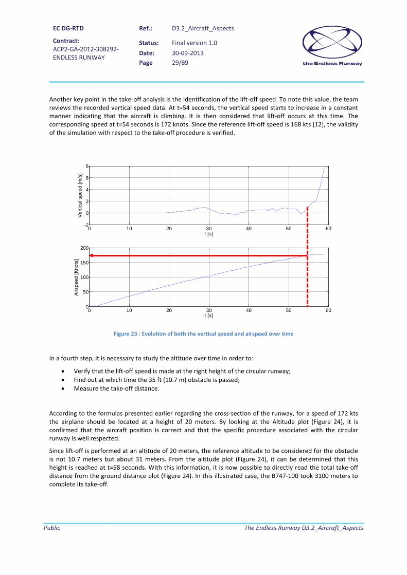
Another key point in the take-off analysis is the identification of the lift-off speed. To note this value, the team reviews the recorded vertical speed data. At t=54 seconds, the vertical speed starts to increase in a constant manner indicating that the aircraft is climbing. It is then considered that lift-off occurs at this time. The corresponding speed at t=54 seconds is 172 knots. Since the reference lift-off speed is 168 kts [12], the validity of the simulation with respect to the take-off procedure is verified.
Figure 23 : Evolution of both the vertical speed and airspeed over time
In a fourth step, it is necessary to study the altitude over time in order to:
• Verify that the lift-off speed is made at the right height of the circular runway; • Find out at which time the 35 ft (10.7 m) obstacle is passed; • Measure the take-off distance.
According to the formulas presented earlier regarding the cross-section of the runway, for a speed of 172 kts the airplane should be located at a height of 20 meters. By looking at the Altitude plot (Figure 24), it is confirmed that the aircraft position is correct and that the specific procedure associated with the circular runway is well respected.
Since lift-off is performed at an altitude of 20 meters, the reference altitude to be considered for the obstacle is not 10.7 meters but about 31 meters. From the altitude plot (Figure 24), it can be determined that this height is reached at t=58 seconds. With this information, it is now possible to directly read the total take-off distance from the ground distance plot (Figure 24). In this illustrated case, the B747-100 took 3100 meters to complete its take-off.
0 10 20 30 40 50 60-2
0
2
4
6
8
t [s]
Ver
tical
spe
ed [m
/s]
0 10 20 30 40 50 600
50
100
150
200
t [s]
Airs
peed
[Kno
ts]

EC DG-RTD
Contract: ACP2-GA-2012-308292- ENDLESS RUNWAY
Ref.: D3.2_Aircraft_Aspects
Status: Final version 1.0 Date: 30-09-2013 Page 30/89
Public
The Endless Runway D3.2_Aircraft_Aspects
Figure 24 : Altitude and ground distance variation over time
The last elements to be assessed during the take-off simulation are the required steering to perform the circular movement and the sustained lateral acceleration. The next figure illustrates the value observed with Flight Gear (associated rudder displacement is not shown).
Figure 25 : Steering and lateral acceleration variation over time
0 10 20 30 40 50 60-20
0
20
40
60
t [s]
Alti
tude
[m]
0 10 20 30 40 50 600
1000
2000
3000
4000
t [s]
Gro
und
Dis
tanc
e [m
]
0 10 20 30 40 50 60-5
0
5
10
15
20
t [s]
Ste
erin
g [d
eg]
0 10 20 30 40 50 60-1.5
-1
-0.5
0
0.5
1
t [s]
Acc
eler
atio
n al
ong
Y [m
/s²]

EC DG-RTD
Contract: ACP2-GA-2012-308292- ENDLESS RUNWAY
Ref.: D3.2_Aircraft_Aspects
Status: Final version 1.0 Date: 30-09-2013 Page 31/89
Public
The Endless Runway D3.2_Aircraft_Aspects
Regarding steering, the first plot in Figure 25 shows that the circular movement of the aircraft has been achieved with several discontinuous inputs from the pilot. It is interesting to note that the absolute value of these inputs increased over time to achieve the desired trajectory. The consortium agrees that a continuous controlled steering would improve the overall performances as well as lower steering angles. The second plot in Figure 25 identifies the lateral acceleration related to passenger comfort. The idea is to verify that during the circular trajectory during take-off, the sustained accelerations do not exceed 1.2 m/s² [31]. The recorded data show a maximum value of 1 m/s², indicating thus that the performed maneuver would be below discomfort for passengers. For the subsequent multi-criteria assessment, it is decided to take into consideration average values regarding steering and lateral acceleration. In the presented simulation, the calculated values are:
• Average steering angle : 2.4 deg (for the ground run) • Average absolute lateral acceleration : 0.37 m/s²
3.5.4.3 Square root speed distribution
This section will analyze the take-off performance of the B747-100 taking of the Endless runway when a square root speed distribution is used to define the runway cross section.
The same plots as described in the previous section are reviewed for take-off simulations performed on a circular runway with a cross section defined by a square root speed distribution. In Figure 26, the aircraft trajectory during take-off is shown (it is important to note that this take-off is completed in the other direction when compared to Figure 26). The circular path is visible as well as the airborne segment that is considered in the analysis.
Figure 26 : Take-off flight path
The first step in the analysis focuses on the determination of the rotation speed. With this objective, the elevator position is reviewed to determine the time at which the pilot commanded the rotation. Figure 27
0
500
1000
1500
-2000
200400
600800
10000
20
40
60
80
x [m]
Flight Path
y [m]
z [m
]

EC DG-RTD
Contract: ACP2-GA-2012-308292- ENDLESS RUNWAY
Ref.: D3.2_Aircraft_Aspects
Status: Final version 1.0 Date: 30-09-2013 Page 32/89
Public
The Endless Runway D3.2_Aircraft_Aspects
shows that the input is given at t=53 seconds. At this time, the airspeed is about 161 knots. Since the rotation speed provided in the reference document [12] is 160 knots, the resulting small difference indicates that the simulation is performed correctly.
Figure 27 : Evolution of both the airspeed and the normalized elevator position over time
Once this verification about the pilot inputs is made, the subsequent step is the determination of lift-off speed. This value is measured by looking at the recorded vertical speed:
Figure 28 : Evolution of both the vertical speed and airspeed over time
0 10 20 30 40 50 60 700
50
100
150
200
t [s]
Airs
peed
[Kno
ts]
0 10 20 30 40 50 60 70-0.8
-0.6
-0.4
-0.2
0
t [s]
Ele
vato
r Pos
ition
Nor
m. [
-]
0 10 20 30 40 50 60 70-5
0
5
10
t [s]
Ver
tical
spe
ed [m
/s]
0 10 20 30 40 50 60 700
50
100
150
200
t [s]
Airs
peed
[Kno
ts]
EC DG-RTD
Contract: ACP2-GA-2012-308292- ENDLESS RUNWAY
Ref.: D3.2_Aircraft_Aspects
Status: Final version 1.0 Date: 30-09-2013 Page 33/89
Public
The Endless Runway D3.2_Aircraft_Aspects
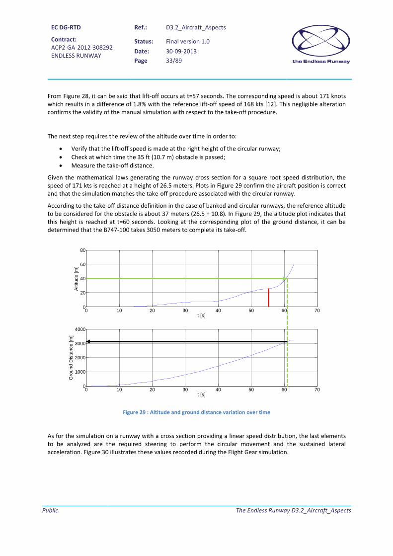
From Figure 28, it can be said that lift-off occurs at t=57 seconds. The corresponding speed is about 171 knots which results in a difference of 1.8% with the reference lift-off speed of 168 kts [12]. This negligible alteration confirms the validity of the manual simulation with respect to the take-off procedure.
The next step requires the review of the altitude over time in order to:
• Verify that the lift-off speed is made at the right height of the circular runway; • Check at which time the 35 ft (10.7 m) obstacle is passed; • Measure the take-off distance.
Given the mathematical laws generating the runway cross section for a square root speed distribution, the speed of 171 kts is reached at a height of 26.5 meters. Plots in Figure 29 confirm the aircraft position is correct and that the simulation matches the take-off procedure associated with the circular runway.
According to the take-off distance definition in the case of banked and circular runways, the reference altitude to be considered for the obstacle is about 37 meters (26.5 + 10.8). In Figure 29, the altitude plot indicates that this height is reached at t=60 seconds. Looking at the corresponding plot of the ground distance, it can be determined that the B747-100 takes 3050 meters to complete its take-off.
Figure 29 : Altitude and ground distance variation over time
As for the simulation on a runway with a cross section providing a linear speed distribution, the last elements to be analyzed are the required steering to perform the circular movement and the sustained lateral acceleration. Figure 30 illustrates these values recorded during the Flight Gear simulation.
0 10 20 30 40 50 60 700
20
40
60
80
t [s]
Alti
tude
[m]
0 10 20 30 40 50 60 700
1000
2000
3000
4000
t [s]
Gro
und
Dis
tanc
e [m
]

EC DG-RTD
Contract: ACP2-GA-2012-308292- ENDLESS RUNWAY
Ref.: D3.2_Aircraft_Aspects
Status: Final version 1.0 Date: 30-09-2013 Page 34/89
Public
The Endless Runway D3.2_Aircraft_Aspects
Figure 30 : Steering and lateral acceleration variation over time
As in section 3.5.4.2, the steering plot of Figure 30 indicates that the circular path of the B747-100 has been obtained thought discontinuous and increasing inputs from the pilot. Once again, a continuous controlled steering would allow better overall performances as well as lower steering angles. It must be noted that the steering values are in this case negative because of the direction of take-off. The second plot of Figure 30 shows the lateral accelerations that are correlated to passenger comfort. In this case, it can be seen that the value of 1.2 m/s² is never exceeded. A take-off on a circular runway with a cross-section generating a square root speed distribution would then be acceptable from a passenger point of view. The average values obtained for this simulation are:
• Average steering angle : -3.8 deg (for the ground run) • Average absolute lateral acceleration : 0.38 m/s²
3.5.4.4 Square speed distribution
The square speed distribution results in a really radical cross section that is not suitable for taking-off with the B747-100. Several attempts have been made but all were unsuccessful. This cross section will therefore not be investigated in this assessment.
3.5.5 Assessment
After completion of the take-off simulations and the associated data analyses, a multi-criteria assessment has been made to identify the best runway cross-section. In a second step, additional points are investigated in order to converge to the definitive runway width.
0 10 20 30 40 50 60 70-50
-40
-30
-20
-10
0
t [s]
Ste
erin
g [d
eg]
0 10 20 30 40 50 60 70-1
-0.5
0
0.5
1
1.5
t [s]
Acc
eler
atio
n al
ong
Y [m
/s²]

EC DG-RTD
Contract: ACP2-GA-2012-308292- ENDLESS RUNWAY
Ref.: D3.2_Aircraft_Aspects
Status: Final version 1.0 Date: 30-09-2013 Page 35/89
Public
The Endless Runway D3.2_Aircraft_Aspects
3.5.5.1 Square root speed vs. linear speed distribution for a reference width of 140 meters
To compare the two possible speed distributions, the assessment has been made concerning the three main performance criteria:
• The take-off distance; • The average absolute lateral acceleration; • The average steering angle.
Besides, elements related to the runway itself are taken into consideration:
• The runway maximum height; • The runway volume.
In addition, a more qualitative element is introduced. It is called “Pilot feedback” and it corresponds to the user appreciation of the difficulty to perform a take-off in a manual manner. Since taking-off from a straight and flat runway is the easiest option, the value for this, will be indicated as 10. Regarding the linear speed distribution, the manoeuver requires some experience and there is always a risk of touching the ground. A value of 5 is then reported. Lastly, since maneuvering on a runway defined by a square root speed distribution is easier, an appreciation of 7 is given. The following table synthesizes all inputs related to the different cross sections:
Table 4 : Summary table to select the runway cross section for a reference width of 140 meters
Conventional runway
Linear speed distribution
Square root speed distribution
Take-off distance [m] 2860 3100 3050
Average absolute lateral acceleration [m/s²] - 0.37 0.38
Average steering angle [deg] - 2.4 3.8
Pilot feedback 10 5 7
Runway maximum height [m] 0 31 47
Runway volume [m3] - 11 274 459 22 652 185
When looking at the efficiency of an airport, the take-off distance is a key parameter. With regard to this aspect, the square root speed distribution is preferable since the distance with respect to the linear speed distribution is shorter (6.6% increase with respect to the standard runway while the linear speed distribution results in an 8.4% increase). As important as the performance aspect, the cost related to the construction of an Endless Runway is paramount. From this point of view, the linear speed distribution is the best option.
Since the Entry Into Service (EIS) of the Endless Runway would be about 2050, it can be foreseen that the operations would be fully automated. In this case, the pilot feedback is no more relevant in the comparison. The same can be said about lateral accelerations and average steering: in 2050, a specific control system could be installed to allow continuous small actuations decreasing thus the peak values. Therefore, the choice to be made is about performance against cost.

EC DG-RTD
Contract: ACP2-GA-2012-308292- ENDLESS RUNWAY
Ref.: D3.2_Aircraft_Aspects
Status: Final version 1.0 Date: 30-09-2013 Page 36/89
Public
The Endless Runway D3.2_Aircraft_Aspects
Even if the square root speed distribution is better from a performance point of view, the difference is negligible while differences regarding the size of the runway (and thus cost) are not. For these reasons, the runway cross section following a linear speed distribution is selected as the most promising solution.
3.5.5.2 Selection of the reference width
With the runway cross-section fixed, simulations are performed with reference widths of 130 meters and 150 meters. From a performance point of view, the differences regarding the take-off distance appear to be negligible. When looking at the runway volume (cost aspects), a width of 130 meters is preferable. Simulations on a runway with a smaller width resulted in high lateral accelerations.
Figure 31 : Observed lateral accelerations during a take-off for a reference width of 130 m
The previous figure shows that the limit of 1.2 m/s² set in [16] is exceeded during the ground run on the circular runway with a width of 130 meters. Even if future aircraft could be equipped with a control system allowing a better automated trajectory resulting in lower acceleration, a width of 140 meters is to be preferred. Regarding the 150 meters option, no real benefits have been pointed out by the simulation. The consortium fixes then the reference runway width to 140 meters.
To conclude the aspects related to the runway width, a complete runway cross section is illustrated in the next figure:
Figure 32 : Runway cross section (B747-100 is positioned at the height corresponding to the rotation speed)
0 10 20 30 40 50 60 70-0.5
0
0.5
1
1.5
2
t [s]
Acc
eler
atio
n al
ong
Y [m
/s²]
EC DG-RTD
Contract: ACP2-GA-2012-308292- ENDLESS RUNWAY
Ref.: D3.2_Aircraft_Aspects
Status: Final version 1.0 Date: 30-09-2013 Page 37/89
Public
The Endless Runway D3.2_Aircraft_Aspects
For aircraft that operates on the curved surface, the available width is larger than the reference length. In order to avoid an abrupt end of the runway below the wing tip (asymmetric aerodynamics), a linear portion is added (blue line in Figure 32). Airport designers have to consider this additional part as well as the external shape of the Endless Runway considering safety aspects (dashed line in Figure 32).
3.5.6 Landings
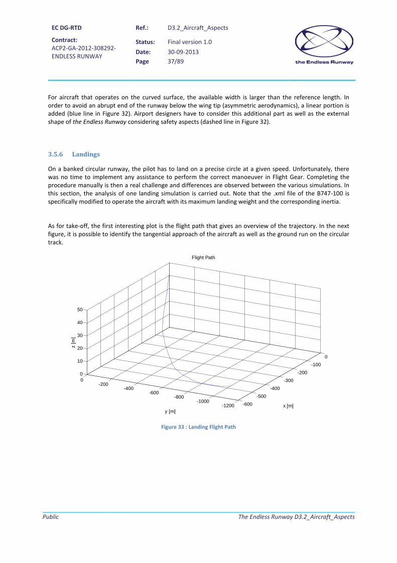
On a banked circular runway, the pilot has to land on a precise circle at a given speed. Unfortunately, there was no time to implement any assistance to perform the correct manoeuver in Flight Gear. Completing the procedure manually is then a real challenge and differences are observed between the various simulations. In this section, the analysis of one landing simulation is carried out. Note that the .xml file of the B747-100 is specifically modified to operate the aircraft with its maximum landing weight and the corresponding inertia.
As for take-off, the first interesting plot is the flight path that gives an overview of the trajectory. In the next figure, it is possible to identify the tangential approach of the aircraft as well as the ground run on the circular track.
Figure 33 : Landing Flight Path
-600-500
-400-300
-200-100
0
-1200-1000
-800-600
-400-200
00
10
20
30
40
50
x [m]
Flight Path
y [m]
z [m
]

EC DG-RTD
Contract: ACP2-GA-2012-308292- ENDLESS RUNWAY
Ref.: D3.2_Aircraft_Aspects
Status: Final version 1.0 Date: 30-09-2013 Page 38/89
Public
The Endless Runway D3.2_Aircraft_Aspects
To point out issues concerning the touchdown point, it is useful to examine the landing gear compression. In Figure 33, it can be seen that the impact with the track occurs at t=6 seconds. At this time, the airspeed is about 137 knots. The difference of 5% with the reference speed provided in [12] is acceptable.
Figure 34 : Evolution of the landing gear compression and the airspeed over time
According to the runway cross-section formulas, a speed of 137 knots corresponds to a height of 10 meters above the ground. Since the definition of the landing distance requires a clearance over a 15 meters obstacle, it can be said that the landing distance must be calculated from the point where the altitude of the aircraft is 25 meters. In Figure 34, it can be observed that the altitude of 25 meters is reached at t=4 seconds. The ground distance corresponds then to 1900 meters.
0 10 20 30 40 50 600
0.1
0.2
0.3
0.4
t [s]
L.G
.2com
pres
sion
0 10 20 30 40 50 600
50
100
150
t [s]
Airs
peed
[Kno
ts]

EC DG-RTD
Contract: ACP2-GA-2012-308292- ENDLESS RUNWAY
Ref.: D3.2_Aircraft_Aspects
Status: Final version 1.0 Date: 30-09-2013 Page 39/89
Public
The Endless Runway D3.2_Aircraft_Aspects
Figure 35 : Altitude and ground distance evolution over time
Regarding the passenger comfort, the plot of the sustained lateral accelerations presented here below shows that the limit of 1.2 m/s² is exceeded several times (red circles). However, the average value of the acceleration is 0.66 m/s².
Figure 36 : Lateral acceleration evolution over time
Because of the difficulty of the manual approach used for landing simulations, it is preferable to review other telemetries before defining the performance. Since the previous simulation has a low landing speed, the consortium decided to perform a landing with a higher speed (150 knots). The next figure shows the resulting landing distance knowing that the FAR obstacle is cleared at t=2 seconds.
0 10 20 30 40 50 60-20
0
20
40
60
t [s]
Alti
tude
(m]
0 10 20 30 40 50 600
500
1000
1500
2000
2500
t [s]
Gro
und
Dis
tanc
e [m
]
0 10 20 30 40 50 60-3
-2
-1
0
1
2
t [s]
Acc
eler
atio
n al
ong
Y [m
/s²]

EC DG-RTD
Contract: ACP2-GA-2012-308292- ENDLESS RUNWAY
Ref.: D3.2_Aircraft_Aspects
Status: Final version 1.0 Date: 30-09-2013 Page 40/89
Public
The Endless Runway D3.2_Aircraft_Aspects
Figure 37 : Landing distance measured for another simulation (higher landing speed)
In this case, the landing distance is about 2400 meters. With data gathered from other simulations, an average value of 2200 meters can be defined as the landing distance for the B747-100 on a circular runway.
3.5.7 B747-100 ground clearance analysis
In Figure 37, a front view of the B747-100 ([32]) allows to measure the fixed reference distance d3 as well as the distances d1 and d2 for the critical elements, in this case the wingtips. d1 and d2 are also reported for both the inner and outer engines.
Figure 38 - Example of measure taking for the wingtips of the B747-100
The measures are reported in Table 5.
0 10 20 30 40 50 60 700
1000
2000
3000
t [s]
Gro
und
Dis
tanc
e [m
]
d3 d2
d1

EC DG-RTD
Contract: ACP2-GA-2012-308292- ENDLESS RUNWAY
Ref.: D3.2_Aircraft_Aspects
Status: Final version 1.0 Date: 30-09-2013 Page 41/89
Public
The Endless Runway D3.2_Aircraft_Aspects
Table 5 : B747-100 key distances for ground clearance calculation
Landing gear d3 6,3 [m]
Inner engine d1 1,7 [m]
d2 12,3 [m]
Outer engine d1 2,5 [m]
d2 21,5 [m]
Wingtip d1 6,2 [m]
d2 30,0 [m
Based on the mathematical formulas developed in Appendix B.3, a routine developed in Python (high-level programming language) computes the distance values and indicates the corresponding position of the aircraft on the linear speed distribution. The results are presented in Table 6.
Table 6 : B747-100 ground clearance calculations
Nominal distance on flat ground
(m)
Internal aircraft side External aircraft side Minimum
distance (m) Corresponding abscissa of the center of the
landing gear (m)
Minimum distance (m)
Corresponding abscissa of the center of the
landing gear (m) Outer engine 2,5 1,18 127,5 1,35 113,8 Inner engine 1,7 1,27 103,9 1,42 128,5 Wingtip 6,2 3,55 120,6 3,68 103,9
As seen in chapter 3.5.4.2, the B747-100 lift-off speed observed during the simulation is 172 kts (88,5 m.s-1). Therefore, according to Figure 16 (Speed distribution), the aircraft will never roll beyond the 1620 m radius runway circle. Hence the most critical element, that is to say the downhill outer engine, will actually have a clearance greater than 1,18 meters that occurs on radius 1627,5 m.
To conclude, all aircraft elements remain clear from the ground with sufficient margin during the ground roll.
3.6 Conclusions on exchange parameters The simulations performed in Flight Gear on a validated B747-100 model enabled the consortium to define the parameters to operate The Endless Runway:
• Size of the circle (radius) The first simulations in Flight Gear showed that the value of 1500 meters for the internal radius of the runway was not a stopper from an aircraft point of view.
• Profile of the runway (bank angle) Simulations with a B747-100 (validated on straight runways) in Flight Gear and the subsequent analysis of the flight parameters indicated that the most promising cross-section is the one associated with a linear speed distribution.

EC DG-RTD
Contract: ACP2-GA-2012-308292- ENDLESS RUNWAY
Ref.: D3.2_Aircraft_Aspects
Status: Final version 1.0 Date: 30-09-2013 Page 42/89
Public
The Endless Runway D3.2_Aircraft_Aspects
• Width of the runway
Since the width does not have a strong impact on the take-off distance, it is fixed to 140 meters to limit the size of the Endless Runway. A smaller width is not recommended because of the resulting higher lateral acceleration.
• Aircraft landing gear During take-off and landing operations performed with the B747-100 model in Flight Gear, the landing gear struts always operated within the defined ranges.
• Take-off performance From the simulations and the subsequent data analysis, the B747-100 take-off distance on a circular runway is increased of about 10% with respect to its reference value (in a curved abscissa).
• Landing performance From the simulations and the subsequent data analysis, the B747-100 landing distance on a circular runway is increased of about 13% with respect to its reference value (in a curved abscissa).
• Lateral acceleration The B747-100 simulations performed in Flight Gear indicated that the lateral accelerations during take-offs are below the accepted limits. For landing, the limit is exceeded for brief periods.

EC DG-RTD
Contract: ACP2-GA-2012-308292- ENDLESS RUNWAY
Ref.: D3.2_Aircraft_Aspects
Status: Final version 1.0 Date: 30-09-2013 Page 43/89
Public
The Endless Runway D3.2_Aircraft_Aspects
New aircraft tailored for the Endless Runway 4.
4.1 Approach The work presented in this chapter corresponds to the activities performed within Task 3.2 “Exploration of new concepts optimized for the Endless Runway”. Since the Endless Runway concept offers a real discontinuity with today’s airport layout, the project also defines an innovative aircraft that would be tailored to the circular runway and its specific procedures. After the definition of the reference mission for this new airplane called “Endless Runway Aircraft Concept” (ERAC), the vehicle configuration is the result of both a concept exploration and an analysis of the specific constraints. Subsequently, ERAC is sized according to the classical approach used in conceptual design. The last step consists in performing simulations within the same environment as in T3.1 to assess ERAC from a performance point of view. This process is illustrated in the following figure.
Figure 39 : Approach to be used in T3.2
4.2 ERAC Conceptual Design
4.2.1 Mission definition
In order to compare the performances of ERAC with the ones calculated for the B747-100, the two aircraft should have a similar purpose. However, the B747-100 being designed in the 1960’s, its classification as “large aircraft” is not valid in 2013 (see aircraft fleet categories detailed in [18]) nor it will be in 2050 for the targeted EIS. The consortium therefore decided to design ERAC according to specifications derived from the B747-100 replacement, the B777-300 [19]:
Propulsion
Flight Dynamics Model : JSBSim
.XML file
Pilot inputs
Computer Screen
Selected shape for the runway
Flight Gear Virtual Mission
Telemetry.txt
ERAC 3D model
Post Flight Analysis
Performance analysis
ERAC conceptual design
Aerodynamics
Sizing processConcept selection
Mission definition

EC DG-RTD
Contract: ACP2-GA-2012-308292- ENDLESS RUNWAY
Ref.: D3.2_Aircraft_Aspects
Status: Final version 1.0 Date: 30-09-2013 Page 44/89
Public
The Endless Runway D3.2_Aircraft_Aspects
• The initial cruise altitude is set to 33 000 ft as for today’s airplanes; • The seating capacity is fixed to 450 passengers divided into 2 classes; • The design range of 8000 NM is approaching the one of the B777-300 Extended Range in order to
match the value indicated for large aircraft in [18]. It is indeed assumed that future twin-aisle aircraft would have the same range as today’s large aircraft.
• The cruise speed is established to Mach 0.8
It can be surprising to have the ERAC cruise speed set to M=0.8 while the B777-300 currently flies at M=0.84. The reason behind this assumption is that several prospective studies presented in [18] recommend a reduction of the cruise speed for environmental purposes. However, since ERAC is a long range aircraft, a severe reduction in the cruise speed would lead to critical increase of the travel time. The next table illustrates this issue showing the impact of the cruise speed on the duration of a Paris to New York flight (5800 km).
Table 7 : Effect of cruise speed reduction for a Paris to New-York flight
4.2.2 Preliminary requirement analysis
Before exploring aircraft configurations, it is important to carry out a preliminary requirement analysis that takes also into account results from the simulations with the B747-100. First the numerous manual take-offs and landings stressed the possibility to have a contact between the ground and the aircraft components. Thus, the ground clearance must be reduced at all costs. To achieve this goal, the concept exploration has to consider:
• a limited wing span; • a different wing position; • a different engine location.
In addition, the previous simulations have shown that the ground handling of the aircraft is critical and ERAC must therefore provide improvements in this area. Finally, because of the complex manoeuver at low speed, ERAC has to be designed in order to have better control in this flight regime.
4.2.3 ERAC Concepts exploration
In the first step of the concept exploration, the idea is to define as many aircraft architectures as possible that match one or more key requirements identified in the previous section. At this stage, the consortium made the assumption that the best control at low speed would be achieved with an increase of the control surfaces. This feature is valid for all proposed architectures. The starting point (or reference configuration) is of course the B747-100 architecture:
Cruise Mach Speed of sound Approx. flight duration DifferenceNumber [m/s] [m/s] [km/h] [h] [%]
0.6 295 177 637.2 9.1 400.65 295 191.75 690.3 8.4 29.20.7 295 206.5 743.4 7.8 200.75 295 221.25 796.5 7.3 120.8 295 236 849.6 6.8 50.84 295 247.8 892.08 6.5 00.9 295 265.5 955.8 6.1 -6.7
Airspeed

EC DG-RTD
Contract: ACP2-GA-2012-308292- ENDLESS RUNWAY
Ref.: D3.2_Aircraft_Aspects
Status: Final version 1.0 Date: 30-09-2013 Page 45/89
Public
The Endless Runway D3.2_Aircraft_Aspects
Figure 40 : Reference configuration (4 engines)
In order to improve the ground clearance, a first option leads to reduce the number of engines (keeping the same overall thrust) and to locate them in the best position along the span, that is to say closer to the fuselage as the external engines were the problematic ones. Particular attention should be given in this case to the critical diameter of the more powerful engines.
Figure 41 : Classical configuration with 2 engines
In order to improve the ground stability a common rule recommends to increase the distance between the main landing gears. Moreover, this will increase the ground clearance of aircraft critical elements. The design team has identified four architectures that are based on two smaller fuselages. The idea is to account for the same passenger capacity, but to allow a larger landing gear track. Following this main idea, four options are proposed with variations on the engine number, position and lifting surfaces layout.
1 TraditionalREFERENCE Classic
AIRCRAFT number 4location Wing
LowClassic
Multi-Bogey
ConfigurationFuselage
Engine
WingTail
Landing Gear
2 Configuration TraditionalFuselage ClassicEngine number 2
location WingWing LowTail Classic
Landing Gear Multi-Bogey

EC DG-RTD
Contract: ACP2-GA-2012-308292- ENDLESS RUNWAY
Ref.: D3.2_Aircraft_Aspects
Status: Final version 1.0 Date: 30-09-2013 Page 46/89
Public
The Endless Runway D3.2_Aircraft_Aspects
3 Double FuselageDouble Fuselage
number 3location Wing
HighClassic
Multi-BogeyLanding Gear
WingTail
ConfigurationFuselage
Engine
4 Double FuselageDouble Fuselage
number 2location Wing
HighClassic
Multi-Bogey
Wing
ConfigurationFuselage
Engine
TailLanding Gear
5 Double FuselageDouble Fuselage
number 2location Tail
LowT
Multi-Bogey
ConfigurationFuselage
Engine
WingTail
Landing Gear

EC DG-RTD
Contract: ACP2-GA-2012-308292- ENDLESS RUNWAY
Ref.: D3.2_Aircraft_Aspects
Status: Final version 1.0 Date: 30-09-2013 Page 47/89
Public
The Endless Runway D3.2_Aircraft_Aspects
Figure 42 : Bi-fuselage configurations
Still with the idea to increase the landing gear track, a less impressive but also very innovative option is the double-bubble fuselage. This name comes after the shape of the structural cross section of the fuselage.
Figure 43 : Large fuselage configuration
6Triple Surface
Double FuselageDouble Fuselage
number 2location Tail
LowClassic
Multi-Bogey
Configuration
Fuselage
Engine
WingTail
Landing Gear
7 ClassicDouble Bubble Section
number 2location Tail
LowT
Multi-BogeyTail
Landing Gear
ConfigurationFuselage
Engine
Wing
8 ClassicDouble Bubble Section
number 2location Wing
HighΠ
Multi-BogeyTail
Landing Gear
ConfigurationFuselage
Engine
Wing

EC DG-RTD
Contract: ACP2-GA-2012-308292- ENDLESS RUNWAY
Ref.: D3.2_Aircraft_Aspects
Status: Final version 1.0 Date: 30-09-2013 Page 48/89
Public
The Endless Runway D3.2_Aircraft_Aspects
Introduced by MIT in the NASA N+3 studies [11], this solution, as illustrated in the previous figure, results in a larger (and automatically shorter) fuselage. In this case, the main landing gear can be moved along the span to increase its track. The proposed configurations are based on changes on the wing position as well as the engine position.
As described in [18], the flying wing configuration is often cited as a possible architecture for 2050 EIS airplanes. Its aerodynamic efficiency makes it indeed an appealing option for long range missions. It is then naturally considered as a possible candidate for ERAC.
Figure 44 : Flying wing configuration
The last configuration to be considered for ERAC is derived from the ATR architecture [20]. This aircraft has a high wing that reduces ground clearance problems. Then, the idea is to extend the lower structure of the fuselage connected to the landing gear to achieve a larger track. Such solution requires a tailored fairing on this lower portion of the airframe to minimize the aerodynamic degradation.
Figure 45 : large landing gear fairing configuration
9 Flying WingNo Fuselage
number 2location -
--
Multi-Bogey
Engine
WingTail
Landing Gear
ConfigurationFuselage
10 Configuration TraditionalFuselage ClassicEngine number 2
location WingWing HighTail T
Landing Gear Multi-Bogey

EC DG-RTD
Contract: ACP2-GA-2012-308292- ENDLESS RUNWAY
Ref.: D3.2_Aircraft_Aspects
Status: Final version 1.0 Date: 30-09-2013 Page 49/89
Public
The Endless Runway D3.2_Aircraft_Aspects
Regarding configuration N°2, preliminary estimations of the necessary thrust lead to an important size of the engines that will be closer to the ground. Thus, this configuration still has ground clearance issues. For configurations N°3 to N°6, even though the ground stability would be increased, the quadricycle layout is not recommended for unconventional runways [21]. Another drawback of these configurations is that the two-fuselage architecture results in a significant increase of the wing span. For the Endless Runway concept, this is a major drawback. Concerning the flying wing option, it has several interesting assets such as the possibility to have a tri-cycle layout for the landing gear with a large track. On the other hand, a known disadvantage is its poor controllability at low speeds. This is a clear stopper when designing an aircraft tailored for the Endless Runway concept. Concerning configuration N°10, preliminary aerodynamics assessments indicated that even if well optimized, the fairing would lead to an important drag penalty. For a long range mission aircraft such as ERAC, the result would be a non-acceptable fuel consumption.
The down-selection converges then to configurations N°7 and N°8 as the most promising ERAC architecture, both based on the double-bubble fuselage. However, a closer look to configuration N°8 reveals that the fuselage would require local reinforcements: one in the upper area to fix the wing box and a second one in the lower area to withstand the landing gear loads. In this case, the fuselage weight would be higher than the one obtained for configuration N°7.
The consortium decides therefore that configuration N°7 is the most promising option for ERAC. Its main features are synthesized here below:
• Double bubble fuselage; • Low wing; • T-Tail empennage; • Two engines located in the rear fuselage.
4.2.4 ERAC sizing
4.2.4.1 Sizing process
In order to size ERAC, the design team combines a conventional statistical analysis [22] and the method presented by Jenkinson in [23]. The overall process is illustrated in the next figure:
Figure 46 : Sizing process flow diagram

EC DG-RTD
Contract: ACP2-GA-2012-308292- ENDLESS RUNWAY
Ref.: D3.2_Aircraft_Aspects
Status: Final version 1.0 Date: 30-09-2013 Page 50/89
Public
The Endless Runway D3.2_Aircraft_Aspects
The statistical analysis requires at first to gather an important database of existing transport aircraft parameters. These data can focus on the overall aircraft (MTOW, cruise speed, etc.) or on certain components (empennages). Subsequently, interpolation rules are defined between the values and various independent variables (among them, the key mission figures: Mach, number of passengers, range) in order to provide a first estimation of ERAC’s geometry and MTOW. Table 10 presents the airplanes that have been used to generate the database. It must be nothed that empennage data for the Airbus A350 and Boeing B787 have not been included in the calculation of the interpolation rules.
Table 8 : Aircraft database for statistical analysis
However, ERAC is an unconventional airplane and such conceptual sizing based on historical data may lead to biased values. For this reason, the sizing process includes an iterative calculation of the necessary mission fuel and the weight estimation of the aircraft components (semi-empirical equations) as recommended in [23]. In order to complete this mission sizing, several assumptions have been made:
• Since ERAC targets an EIS in 2050, the specific fuel consumption (SFC) has to consider evolutions that could be made in the next decades. In [24], a reduction of 15% to 20% for the SFC is indicated. Therefore, during the mission sizing, a value of 15% is taken to keep a conservative approach.
• Given the long term EIS of ERAC, the mission sizing must also consider the future progress regarding aircraft materials and structures. It is then assumed that composites will be fully mastered and applied on the main wing, control surfaces and empennage leading to a weight reduction of 20% with respect to today’s data. For the nacelles, improvements are fixed to a lower value (10%) since composites are already used and the margin for improvement is smaller.
• ERAC is based on the innovative fuselage called Double Bubble proposed in [11]. The complexity of such structure cannot be captured by the equations proposed in [23]. However, this reference indicates a range for the fuselage with respect to MTOW between 7% and 12%. It is therefore decided to set the fuselage weight to 9% of MTOW to take into account a probable heavier structure because of the Double Bubble concept that is compensated by the use of advanced materials. This value is also corroborated by data obtained according to formulas provided in [22].
Manufacturer Model Version Manufacturer Model Version
300 600 R 747 100310 300 747 200320 200 747 400321 200 757 200330 200 757 300330 300 767 200340 200 767 200 ER340 300 767 300340 500 767 300 ER340 600 767 400350 800 777 200 ER 350 900 787 8350 1000 787 9
DC10 10 787 10DC10 30 Ilyushin Il-96 MMD11 ERMD12 HC
Airbus
McDonnel Douglas
Boeing

EC DG-RTD
Contract: ACP2-GA-2012-308292- ENDLESS RUNWAY
Ref.: D3.2_Aircraft_Aspects
Status: Final version 1.0 Date: 30-09-2013 Page 51/89
Public
The Endless Runway D3.2_Aircraft_Aspects
• To calculate the fuel consumption, the efficiency of ERAC must also be estimated. In order to be conservative, the design team made a 5% reduction of the calculated lift-to-drag ratio in [11] for the long range mission. The mission sizing considers then a cruise lift-to-drag of 20.
Figure 47 : Double Bubble concept defined by the MIT team for a long range mission [11]
• To set the payload mass, it is assumed that a passenger weights about 75 kg, to which 20 kg of luggage must be added. For 450 passengers, the resulting payload weight is 42750 kg.
• Given future’s trends regarding on-board systems, it can be foreseen that in 2050, ERAC would be an all-electric aircraft (the propulsion system is still based on kerosene). However, it has been decided to design ERAC following today’s standing that is “a more electrical aircraft”. For this reason, the aircraft sizing still considers some hydraulic components.
4.2.4.2 Engine selection
The engine selection is a critical step in the sizing of a new aircraft concept. In order to determine in an accurate manner the required thrust for ERAC, the design team decided to follow the method proposed by Mattingly in [25]. In this approach, the different phases of the mission are analyzed from a performance point of view and described with an equation that relates the thrust-to-weight ratio (T/W) and the wing loading (W/S) of an airplane. Subsequently, constraints for the different segments are taken into account in the equations. By plotting the evolution of T/W versus W/S (a graph called “constraint diagram”), it is then possible to identify the possible combinations that match the requirements. For ERAC sizing, a preliminary

EC DG-RTD
Contract: ACP2-GA-2012-308292- ENDLESS RUNWAY
Ref.: D3.2_Aircraft_Aspects
Status: Final version 1.0 Date: 30-09-2013 Page 52/89
Public
The Endless Runway D3.2_Aircraft_Aspects
review of the mission phases indicated that the most critical one regarding the engine sizing is as expected the take-off phase. For this reason, only the relationship between T/W and W/S for take-off has been examined.
As a design objective, it is decided that ERAC should take-off in less than 3000 meters on an Endless Runway to have an improvement with respect to the B747-100 (3100 m). However, the constraint analysis proposed in [25] considers a classical take-off on a straight runway. Since the previous chapter detailing the B747-100 simulation showed an increase of the take-off distance about 9%, the take-off field length constraint has then been fixed to 2500 meters. Such value in the early stages of the design process is voluntarily conservative in order to take into account possible performance degradations that are not yet identified. In addition, the design team considered the possibility to operate from an airport located at 3000 ft. This latest requirement shifts the feasibility zone in the constraint diagram as illustrated below:
Figure 48 : ERAC constraint diagram (take-off phase only)
In Figure 47, all feasible T/W and W/S combinations that meet the 2500 meters take-off distance on an airport at 3000 ft are on or above the red line. As complementary information, values of existing airplanes have been added on the constraint diagram.
During the sizing of an airplane designed to take-off and land from a conventional runway, designers have the freedom to choose the most appropriate values for the wing-loading and the T/W ratio. In the case of an airplane tailored to the circular track, the problem is somewhat different: because of ground clearance issues, the span (and thus the wing area) is limited. Thus, the only real variable parameter is the engine thrust.
From a practical point of view, with the MTOW and wing area of ERAC converging to their definitive value after a few iterations, it has been possible to fix its wing loading and to identify the required thrust. With this value, the most suitable engine has been selected. The consortium prefers indeed to take an existing engine instead of non-existing one based on the semi-empirical model defined in [14] matching the exact required thrust to

EC DG-RTD
Contract: ACP2-GA-2012-308292- ENDLESS RUNWAY
Ref.: D3.2_Aircraft_Aspects
Status: Final version 1.0 Date: 30-09-2013 Page 53/89
Public
The Endless Runway D3.2_Aircraft_Aspects
have even more reliable reference data on weight, geometric characteristics and consumption to which technological improvements are then applied.
This approach results in installing on ERAC an evolution of the GE90-94B (used on today’s B777). For a wing loading of about 680 kg/m², T/W equals then to 0.327, a number that is above the constraint limit. To take into account the evolutions to be made on this engine in the next decades (2050 EIS), designers decided to keep the geometry, mass and thrust level constant and to reduce the Thrust Specific Fuel Consumption (TSFC) by 15%. The sizing process considers then an engine with the following characteristics:
• Maximum thrust at sea level : 416.5 kN; • Maximum diameter : 3.4 m; • Total length : 7.3 m; • Weight : 7550 Kg; • TSFC : 0.458 lb/h/lbf
4.2.4.3 ERAC geometry
At the end of the sizing process, the main geometrical parameters of ERAC are defined. The next table details their values:
Table 9 : ERAC main geometrical data
4.2.4.4 ERAC weight breakdown
After several iterations between the statistical analysis and the mission sizing according to Jenkinson’s method, the process converges to a final value of MTOW and the weight breakdown is completed. The following table details ERAC weight breakdown:
Length 66.4 [m]Maximum width 8.7 [m]
Span 61 [m]Sweep (1/4 chord) 29 [°]Area 392 [m²]Taper ratio 0.2
Span 20.9 [m]Sweep (1/4) chord 31 [°]Area 81.5 [m²]Taper ratio 0.3
Span 8.1 [m]Sweep (1/4) chord 30 [°]Area 60 [m²]Taper ratio 0.7
FUSELAGE
WING
HORIZONTAL TAIL
VERTICAL TAIL

EC DG-RTD
Contract: ACP2-GA-2012-308292- ENDLESS RUNWAY
Ref.: D3.2_Aircraft_Aspects
Status: Final version 1.0 Date: 30-09-2013 Page 54/89
Public
The Endless Runway D3.2_Aircraft_Aspects
Table 10 : ERAC Weight Breakdown
It is important to note that using solely the statistical analysis would have led to an MTOW of more than 300000 kg (12.6% increase). The coupling of both approaches is then a valuable method that enables designers to decrease uncertainties during the sizing. It is obvious that the assumptions made during the mission sizing have a critical impact on the presented conceptual weight breakdown.
4.2.4.5 Final ERAC sketch
In the final iterations of the sizing process, AVL [26] and OpenVSP [27] have been used in order to respectively calculate aerodynamics properties and to generate 3D models of ERAC. The acquired additional information allows a refinement of the concept. The following figure illustrates the final ERAC sketch obtained with OpenVSP:
Weight [kg] %
Wing 29816 11.2
Control surfaces 2056 0.8Flaps 973 0.4
Empennage 4209 1.6Fuselage 23968 9.0
Landing gear 11585 4.4Nacelles 4484 1.7
Airframe 77091 28.9
Propulsion system 20216 7.6Fixed equipment 21305 8.0
Empty weight 118612 44.5
Mission equipment 7056 2.6Crew 1131 0.4
Operative Empty Weight 126799 47.6
Fuel 96765 36.3Payload 42750 16.1
MTOW 266314 100.0

EC DG-RTD
Contract: ACP2-GA-2012-308292- ENDLESS RUNWAY
Ref.: D3.2_Aircraft_Aspects
Status: Final version 1.0 Date: 30-09-2013 Page 55/89
Public
The Endless Runway D3.2_Aircraft_Aspects
Figure 49 : ERAC 3D sketch
By modeling digital mock-ups, the design team has the possibility to determine the Center of Gravity position in various conditions. Thus, after a few iterations, the design team converges to an optimized position of the various components in order to obtain a satisfactory static margin for ERAC (the neutral point is provided by AVL). With the rear limit of the center of gravity (aft CG position) fixed, the position of the landing has been subsequently set and the shape of the fuselage has been designed in order to obtain the same tip-back angle as the B747-100. Since no ground contact issues have been observed in the earlier simulations with Flight Gear, no changes were necessary in this area.
In addition, OpenVSP enables wet surface calculations for the aircraft main components. These values are very valuable for more accurate calculations of ERAC aerodynamics properties:
• Fuselage wet surface: 1175 m² • Wing wet surface: 627 m² • Horizontal tail wet surface: 163 m²; • Vertical tail wet surface: 119.5 m².
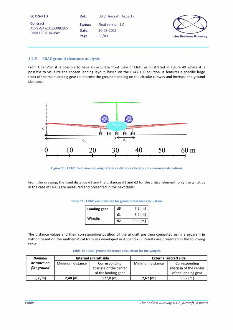
EC DG-RTD
Contract: ACP2-GA-2012-308292- ENDLESS RUNWAY
Ref.: D3.2_Aircraft_Aspects
Status: Final version 1.0 Date: 30-09-2013 Page 56/89
Public
The Endless Runway D3.2_Aircraft_Aspects
4.2.5 ERAC ground clearance analysis
From OpenVSP, it is possible to have an accurate front view of ERAC as illustrated in Figure 49 where it is possible to visualize the chosen landing layout, based on the B747-100 solution. It features a specific large track of the main landing gear to improve the ground handling on the circular runway and increase the ground clearance.
Figure 50 : ERAC front view showing reference distances for ground clearance calculations
From this drawing, the fixed distance d3 and the distances d1 and d2 for the critical element (only the wingtips in the case of ERAC) are measured and presented in the next table:
Table 11 : ERAC key distances for ground clearance calculation
Landing gear d3 7,6 [m]
Wingtip d1 5,2 [m]
d2 30,5 [m]
The distance values and their corresponding position of the aircraft are then computed using a program in Python based on the mathematical formulas developed in Appendix B. Results are presented in the following table:
Table 12 : ERAC ground clearance calculation for the wingtip
Nominal distance on flat ground
Internal aircraft side External aircraft side Minimum distance Corresponding
abscissa of the center of the landing gear
Minimum distance Corresponding abscissa of the center
of the landing gear 5,2 [m] 2,48 [m] 122,8 [m] 2,67 [m] 99,2 [m]
d3 d2
d1

EC DG-RTD
Contract: ACP2-GA-2012-308292- ENDLESS RUNWAY
Ref.: D3.2_Aircraft_Aspects
Status: Final version 1.0 Date: 30-09-2013 Page 57/89
Public
The Endless Runway D3.2_Aircraft_Aspects
As it will be explained in section 4.5.1, the simulated ERAC lift-off speed is about 174 kts (89,5 m.s-1). Therefore, according to Figure 16 (Speed distribution), the aircraft will never roll beyond the 1621 m radius runway circle. Hence the distance to the ground gets in the worst case close to 2,48 m for the downhill wingtip, which is acceptable and is an improvement compared with the B747-100, where the downhill outer engine distance to the runway could get close to 1,18 m.
4.3 ERAC model for Flight Gear
4.3.1 Inertial properties
Classical performance analyses take into account the weight of the aircraft and the center of gravity. In the case of 6DOF simulations, the inertial properties of the aircraft are also required. These parameters have been then determined with OpenVSP that offers the possibility to make the automatic calculation (see Figure 50).
Figure 51 : Inertial properties of ERAC calculated with OpenVSP
The next table details all inertial data calculated for three configurations. Because of symmetry of ERAC, products of inertia IXY and IYZ are fixed to 0.
Table 13 : ERAC inertial properties
MTOW Cruise Zero Fuel Weight
Weight [kg] 266400 218400 169600
XCG [m] 35.3 36 36.9
IXX [Kg.m3] 14656104 11166185 7606613
IYY [Kg.m3] 26970341 26496378 25735984
IZZ [Kg.m3] 40223760 36303717 32054680
IXZ [Kg.m3] 2338700 2239159 2079297

EC DG-RTD
Contract: ACP2-GA-2012-308292- ENDLESS RUNWAY
Ref.: D3.2_Aircraft_Aspects
Status: Final version 1.0 Date: 30-09-2013 Page 58/89
Public
The Endless Runway D3.2_Aircraft_Aspects
4.3.2 Refined aerodynamics study
4.3.2.1 Lift-to-drag ratio verification
During the sizing process, an important assumption has been made regarding ERAC lift-to-drag ratio for the cruise segment (value fixed to 20). To verify the hypothesis, refined aerodynamics calculations with AVL [26] and an estimation of the zero-lift drag coefficient have been performed.
As a first step, the necessary level of lift in cruise must be calculated. Assuming a consumption of half of the fuel and a cruise Mach number equal to 0.8, the reference lift coefficient for the cruise segment is fixed to 0.6517. Subsequently, AVL is used to find the elevator deflection and the angle of attack associated to the trimmed cruise condition. It is important to detail at this point several features of the AVL model that is used:
• The main wing is designed using the supercritical airfoil NASA SC(2)-0412 with a twist law that avoids stall in the ailerons region;
• The horizontal tail uses the same airfoil but upside-down; • The vertical tail uses a NACA 0008 airfoil; • In order to match the specific requirement about a better control at low speed, the control surfaces
(elevator, rudder, ailerons) are sized using the upper values of the statistical data found in [28]; • ERAC fuselage model is based on the D8.1 model that can be found in the AVL package [26] in order
to take into account its contribution to the pitching moment. • The reference Reynolds number is fixed to 39.106.
The figure here below illustrates the resulting loads on ERAC for the cruise trimmed condition:
Figure 52 : Load distribution in the trim condition
The associated AVL outputs indicate that the equilibrium is obtained for:
• α = 0.375°; • δe = 2.8°

EC DG-RTD
Contract: ACP2-GA-2012-308292- ENDLESS RUNWAY
Ref.: D3.2_Aircraft_Aspects
Status: Final version 1.0 Date: 30-09-2013 Page 59/89
Public
The Endless Runway D3.2_Aircraft_Aspects
Figure 53 : ERAC Trefftz Plane
AVL enables also the calculation of the induced drag coefficient CDi. As shown in Figure 52, in the cruised trimmed condition, CDi=0.0147. In order to find the total drag coefficient of ERAC (CDERAC), it is necessary to estimate the zero-lift drag coefficient CD0.
Since CD0 takes into account the form drag, it is difficult to calculate its accurate value without performing numerical simulations. However, given the exploratory purpose of the Endless Runway project, such time consuming calculations are not viable. It is therefore decided to use the program friction.exe from Mason that can be found in [29]. This program offers the possibility to compute both friction and form drag with an accuracy that is sufficient for conceptual design studies. Using information about ERAC geometry available through the OpenVSP model of ERAC (wetted area and length of components), friction.exe provides the following outputs:
• CDfriction= 0.00944; • CDform= 0.00456.
It is then possible to calculate the total drag coefficient of ERAC in the cruise trimmed condition:
𝐶𝐷𝐸𝑅𝐴𝐶 = 𝐶𝐷0 + 𝐶𝐷𝑖 = 𝐶𝐷𝑓𝑟𝑖𝑐𝑡𝑖𝑜𝑟 + 𝐶𝐷𝑓𝑜𝑟𝑚 + 𝐶𝐷𝑖
𝐶𝐷𝐸𝑅𝐴𝐶 = 0.00944 + 0.00456 + 0.0147
𝐶𝐷𝐸𝑅𝐴𝐶 = 0.0287
Knowing that the corresponding lift coefficient is 0.6517, the resulting lift-to-drag ratio is 22.7. This value being superior to the one that has been used in the sizing process, the calculated fuel weight is larger than it could

EC DG-RTD
Contract: ACP2-GA-2012-308292- ENDLESS RUNWAY
Ref.: D3.2_Aircraft_Aspects
Status: Final version 1.0 Date: 30-09-2013 Page 60/89
Public
The Endless Runway D3.2_Aircraft_Aspects
be. The value of ERAC MTOW of 266.4 tons is then higher than it could be. However, since there are some uncertainties related to the assumptions and calculations made during the conceptual study, it is decided that such a conservative approach is preferable and a new sizing process based on this efficiency of 22.7 is not performed.
4.3.2.2 Complementary aerodynamics coefficients for Flight Gear
As for the B747-100 model, Flight Gear requires values for all aerodynamics coefficients (lift, drag, sideforce, rolling moment, pitching moment, yawing moment). Here below are presented the linear equations used to model these aerodynamic coefficients:
• For the lift coefficient:
𝐶𝐿 = 𝐶𝐿0 + 𝐶𝐿𝛼 .𝛼 + 𝐶𝐿𝑞 .𝑞 + 𝐶𝐿𝛿𝑒 . 𝛿𝑒 + ∆𝐶𝐿𝐹𝑙𝑟𝑝
• For the drag coefficient:
𝐶𝐷 = 𝐶𝐷0 + 𝑘.𝐶𝐿2
with
𝐶𝐷0 = 𝐶𝐷𝐹𝑟𝑖𝑐𝑡𝑖𝑜𝑟 + 𝐶𝐷𝐹𝑜𝑟𝑚 + ∆𝐶𝐷𝐿𝑟𝑟𝑑𝑖𝑟𝑔𝐺𝑒𝑟𝑟 + ∆𝐶𝐷𝐹𝑙𝑟𝑝
• For the pitching moment coefficient:
𝐶𝑚 = 𝐶𝑚0 + 𝐶𝑚𝛼 .𝛼 + 𝐶𝑚𝑞 . 𝑞 + 𝐶𝑚𝛿𝑒 . 𝛿𝑒
• For the side force coefficient:
𝐶𝑌 = 𝐶𝑌𝛽 .𝛽 + 𝐶𝑌𝑝 . 𝑝 + 𝐶𝑌𝑟 . 𝑟 + 𝐶𝑌𝛿𝑟 . 𝛿𝑟
• For the rolling moment coefficient:
𝐶𝑙 = 𝐶𝑙𝛽 .𝛽 + 𝐶𝑙𝑝. 𝑝 + 𝐶𝑙𝑟 . 𝑟 + 𝐶𝑙𝛿𝑟. 𝛿𝑟
• For the yawing moment coefficient:
𝐶𝑟 = 𝐶𝑟𝛽 .𝛽 + 𝐶𝑟𝑝. 𝑝 + 𝐶𝑟𝑟. 𝑟 + 𝐶𝑟𝛿𝑟 .𝛿𝑟
AVL is now used to calculate the necessary aerodynamics derivatives at different Mach numbers. The following tables detail the outputs of the aerodynamic assessment:

EC DG-RTD
Contract: ACP2-GA-2012-308292- ENDLESS RUNWAY
Ref.: D3.2_Aircraft_Aspects
Status: Final version 1.0 Date: 30-09-2013 Page 61/89
Public
The Endless Runway D3.2_Aircraft_Aspects
Table 14 : Reference database for the lift coefficent
Table 15 : Reference database for the drag coefficent
Table 16 : Reference database for the pitching moment coefficent
Table 17 : Reference database for the side force coefficient
Table 18 : Additional data for sideforce derivative
Mach CL0 CLα CLq CLδe
[/rad] [/rad/s] [/°]0.1 0.438 5.636 9.77 0.0083
0.25 0.445 5.72 9.9 0.00840.8 0.573 7.225 12.27 0.011
Mach Cdi CL CL² k
0.1 0.00728 0.438 0.192 0.0380.25 0.00754 0.445 0.198 0.0380.8 0.01278 0.573 0.328 0.0389
Mach Cm0 Cmα Cmq Cmδe
[/rad] [/rad/s] [/°]0.1 0.105 -0.5272 -26.29 -0.027
0.25 0.1057 -0.559 -26.66 -0.02750.8 0.1121 -1.217 -33.14 -0.0368
Mach CYβ CYr CYδr
[/rad] [/rad/s] [/°]0.1 -0.2597 0.2506 -0.0029
0.25 -0.2612 0.2523 -0.002950.8 -0.2946 0.2776 -0.00336
α CYp
[/rad/s]-10 -0.46330 0.06210 0.577

EC DG-RTD
Contract: ACP2-GA-2012-308292- ENDLESS RUNWAY
Ref.: D3.2_Aircraft_Aspects
Status: Final version 1.0 Date: 30-09-2013 Page 62/89
Public
The Endless Runway D3.2_Aircraft_Aspects
Table 19 : Reference database for the rolling moment coefficient
Table 20 : Additional data for rolling moment derivative
Table 21 : Reference database for the yawing moment coefficient
Table 22 : Additional data for yawing moment derivative
Regarding the Flap effect in Flight Gear, it is assumed in this first study that ERAC has the same high-lift devices as the B747-100 and they cover the same portion of the main wing. The Flap effects can then be extracted from the NASA reference document [12]. Also, since no changes have been made on the landing gear, its effect on the drag coefficient is the same as reported in [12]. The next table summarizes these impacts for ERAC:
Mach Clβ Clp Clδa
[/rad] [/rad/s] [/°]0.1 -0.1893 -0.395 0.00224
0.25 -0.1921 -0.401 0.002270.8 -0.238 -0.492 0.00281
α Clr
[/rad/s]-10 -0.0440 0.13110 0.3039
Mach Cnβ Cnp Cnr Cnδr
[/rad] [/rad/s] [/rad/s] [/°]0.1 0.0894 -0.0423 -0.0928 0.00129
0.25 0.0898 -0.043 -0.093 0.001310.8 0.0944 -0.0584 -0.1 0.00151
α Cnp
[/rad/s]-10 0.08330 -0.04310 -0.168

EC DG-RTD
Contract: ACP2-GA-2012-308292- ENDLESS RUNWAY
Ref.: D3.2_Aircraft_Aspects
Status: Final version 1.0 Date: 30-09-2013 Page 63/89
Public
The Endless Runway D3.2_Aircraft_Aspects
Table 23 : Changes to CL and CD according to the flap position
Based on the linear equations and the different tables presented earlier, the aerodynamics characteristics are implemented in the Flight Gear .xml file dedicated to ERAC.
4.3.3 3D model
To complete the Flight Gear Model, a 3D model of ERAC must be provided in the .ac format. The consortium uses again the program AC3D from Invis [8] to generate the virtual mock-up based on the three views made with OpenVSP. Figure 53 shows the final model with the Endless Runway project logo on the fuselage. It must be noted that in the AC3D model, the control surfaces are not created. Thus, during simulations, the user is not able to see their rotations following pilot’s inputs. The aircraft behavior on the other hand takes into account deflections since the flight dynamic model relies on the .xml file.
Figure 54 : ERAC 3D model for Flight Gear (.ac format)
Flap ∆CDLandingGear ∆CDFlap ∆CLFlap
0 0.0267 0 020 0.02 0.04 0.430 0.009 0.1 1

EC DG-RTD
Contract: ACP2-GA-2012-308292- ENDLESS RUNWAY
Ref.: D3.2_Aircraft_Aspects
Status: Final version 1.0 Date: 30-09-2013 Page 64/89
Public
The Endless Runway D3.2_Aircraft_Aspects
4.4 ERAC simulations With ERAC flight dynamic model completed and its .ac file validated, it is now possible to make carry out take-off and landing simulations on the circular runway in Flight Gear (Figure 54) to assess the performance of the aircraft.
Figure 55 : Take-off simulation with ERAC on a circular runway
For the Flight Gear simulations and the associated performance analysis, two key parameters are the rotation speed and the landing speed that are directly derived from the stall speed. However, since the aerodynamic model used for ERAC is linear, stall cannot be simulated. Given the aerodynamic characteristics presented earlier in the report, it can be assumed that ERAC stall speed is lower than then one of the B747-100. It is then possible to use a conservative approach that fixes the key reference speeds to the ones of the B747-100. Therefore, ERAC simulations are performed with:
• a rotation speed set to 160 kts; • a landing speed set to 144 kts.
With this approach, the take-off performance comparison between the B747-100 and ERAC will mainly be affected by the increased Thrust-to-Weight ratio (there is a small variation in W/S between the two aircraft).

EC DG-RTD
Contract: ACP2-GA-2012-308292- ENDLESS RUNWAY
Ref.: D3.2_Aircraft_Aspects
Status: Final version 1.0 Date: 30-09-2013 Page 65/89
Public
The Endless Runway D3.2_Aircraft_Aspects
4.5 ERAC performance analysis
4.5.1 Take-off
To analyze the take-off phase of ERAC, the same approach used with the B747-100 simulation is carried out. Again, the first plot to be reviewed is the aircraft trajectory. Illustrated in Figure 55, the flight path shows compliance with the circular take-off on the endless runway concept.
Figure 56 : ERAC Take-off flight path
In a second step, the recorded data are plotted to identify the rotation speed. Therefore, the consortium observes the evolution of the elevator input over time to fix the time at which the pilot commanded the aircraft rotation. In the second plot of Figure 56, it can be seen that the elevator deflection associated with the rotation occurs at t=40 seconds. At that time, the speed equals 166 kts which corresponds to a difference of 3.8% with reference value. The manual maneuver matches then the ideal ground trajectory detailed in [18].

EC DG-RTD
Contract: ACP2-GA-2012-308292- ENDLESS RUNWAY
Ref.: D3.2_Aircraft_Aspects
Status: Final version 1.0 Date: 30-09-2013 Page 66/89
Public
The Endless Runway D3.2_Aircraft_Aspects
Figure 57 : Evolution of the airspeed and the normalized elevator position over time for ERAC
Subsequently, the lift-off speed is verified through the observation of the recorded vertical speed data. From the first plot of Figure 57, it can be seen that ERAC becomes airborne at t=43 seconds. From the second plot of Figure 57, the corresponding lift-off speed is identified (174 knots). With respect to the reference speed provided in [12], the difference is about 3.5%: the manual take-off is then performed accordingly to the reference procedure.
Figure 58 : Evolution of the vertical speed and airspeed over time for ERAC
0 10 20 30 40 50 600
50
100
150
200
t [s]
Airs
peed
[Kno
ts]
0 10 20 30 40 50 60-0.8
-0.6
-0.4
-0.2
0
t [s]
Ele
vato
r Pos
ition
Nor
m. [
-]
0 10 20 30 40 50 60-5
0
5
10
15
20
t [s]
Ver
tical
spe
ed [m
/s]
0 10 20 30 40 50 600
50
100
150
200
t [s]
Airs
peed
[Kno
ts]

EC DG-RTD
Contract: ACP2-GA-2012-308292- ENDLESS RUNWAY
Ref.: D3.2_Aircraft_Aspects
Status: Final version 1.0 Date: 30-09-2013 Page 67/89
Public
The Endless Runway D3.2_Aircraft_Aspects
To conclude the take-off distance analysis, the evolution of the altitude is plotted over time. Given the shape of the runway cross-section, at lift-off (t=43 s), ERAC should be at a height of 21 meters. In the first graph of Figure 58, it is shown that at t=43 seconds, an altitude of 20 meters is reached. With such a small difference compared to the ideal trajectory, the manual take-off simulation is accepted.
Since the definition of the take-off distance (see 3.5.4.1) considers a 35 ft obstacle above the lift-off height, the take-off ground distance in the second graph of Figure 58 must be considered from t=0 to t=46s, when the aircraft reaches 31 meters. According to the recorded data ERAC takes 2450 meters to complete the take-off phase (with all engines operative).
Figure 59 : Altitude and ground distance variation over time for ERAC
The performance analysis is completed by reviewing the steering inputs and lateral accelerations during take-off. The first plot in Figure 59 demonstrates that it is possible to control ERAC during the take-off run with discontinuous inputs (with increasing values) that are never close to the physical limit (70 degrees). The average value is notably low as it reaches 1.6 degrees. The second plot in Figure 59 focuses on the other hand on the lateral accelerations that are sustained by the passengers during the take-off phase. The limit of 1.2 m/s² is never exceeded and the average value is low (0.2133 m/s²).
0 10 20 30 40 50 60-50
0
50
100
150
t [s]
Alti
tude
[m]
0 10 20 30 40 50 600
1000
2000
3000
t [s]
Gro
und
Dis
tanc
e [m
]

EC DG-RTD
Contract: ACP2-GA-2012-308292- ENDLESS RUNWAY
Ref.: D3.2_Aircraft_Aspects
Status: Final version 1.0 Date: 30-09-2013 Page 68/89
Public
The Endless Runway D3.2_Aircraft_Aspects
Figure 60 : Steering and lateral acceleration variation over time for ERAC
4.5.2 Landing
In order to analyze the landing segment carried out with ERAC, the same telemetries as in section 3.5.6 are reviewed. In order to have an overview of the landing phase, the trajectory is plotted in 3 dimensions (Figure 61).
Figure 61 : Landing Flight Path with ERAC
0 10 20 30 40 50 600
5
10
15
20
t [s]
Ste
erin
g [d
eg]
0 10 20 30 40 50 60-2
-1
0
1
2
t [s]
Acc
eler
atio
n al
ong
Y [m
/s²]
-800-700
-600-500
-400-300
-200-100
0
050
100150
200250
300350
400
0
10
20
30
y [m]
Flight Path
x [m]
z [m
]

EC DG-RTD
Contract: ACP2-GA-2012-308292- ENDLESS RUNWAY
Ref.: D3.2_Aircraft_Aspects
Status: Final version 1.0 Date: 30-09-2013 Page 69/89
Public
The Endless Runway D3.2_Aircraft_Aspects
On the previous figure, it is possible to see the trajectory of the air segment that is tangent to the circular runway. In addition, the circular ground run on the runway is visible.
By looking at the recorded value of the landing gear compression ratio, it can be said that touchdown happens at t=4 seconds. At this time, the airspeed is about 136 kts, which is extremely close to the landing speed during simulations with the B747-100.
Figure 62 : Evolution of the landing gear compression and the airspeed over time with ERAC
Given the runway cross-section and its associated speed distribution, such speed is attained when the runway is about 10 meters above the ground (simulation indicates 10.5 meters which shows that the simulated procedure matches the objective). Given the definition of the performance criteria in 3.5.4.1, it can be said that the landing distance starts when the aircraft has an altitude of 26 meters (t=0.5s). The plots presented in Figure 63 indicate then a landing distance of about 1930 meters.
0 5 10 15 20 25 30 35 40 45 500
0.1
0.2
0.3
0.4
t [s]
L.G
.2com
pres
sion
0 5 10 15 20 25 30 35 40 45 500
25
50
75
100
125
150
t [s]
Airs
peed
[Kno
ts]

EC DG-RTD
Contract: ACP2-GA-2012-308292- ENDLESS RUNWAY
Ref.: D3.2_Aircraft_Aspects
Status: Final version 1.0 Date: 30-09-2013 Page 70/89
Public
The Endless Runway D3.2_Aircraft_Aspects
Figure 63 : Altitude and ground distance evolution over time with ERAC
Since the B747-100 and ERAC have approximately the same W/S and the landing speed is the same, this result is not surprising. As for the passenger comfort, the recorded lateral accelerations show that the limit of 1.2 m/s² is never exceeded and the average value is about 0.47 m/s².
Figure 64 : Lateral acceleration evolution over time with ERAC
0 5 10 15 20 25 30 35 40 45 500
10
20
30
t [s]
Alti
tude
(m]
0 5 10 15 20 25 30 35 40 45 500
500
1000
1500
2000
t [s]
Gro
und
Dis
tanc
e [m
]
0 5 10 15 20 25 30 35 40 45 50-1
-0.5
0
0.5
1
1.5
t [s]
Acc
eler
atio
n al
ong
Y [m
/s²]
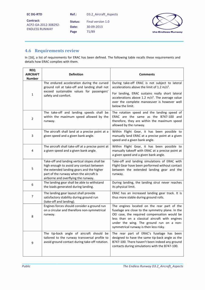
EC DG-RTD
Contract: ACP2-GA-2012-308292- ENDLESS RUNWAY
Ref.: D3.2_Aircraft_Aspects
Status: Final version 1.0 Date: 30-09-2013 Page 71/89
Public
The Endless Runway D3.2_Aircraft_Aspects
4.6 Requirements review In [16], a list of requirements for ERAC has been defined. The following table recalls these requirements and details how ERAC complies with them.
REQ AIRCRAFT Number
Definition Comments
1
The endured acceleration during the curved ground roll at take-off and landing shall not exceed sustainable values for passengers’ safety and comfort.
During take-off ERAC is not subject to lateral accelerations above the limit of 1.2 m/s².
For landing, ERAC sustains really short lateral accelerations above 1.2 m/s². The average value over the complete manoeuver is however well below the limit.
2
The take-off and landing speeds shall be within the maximum speed allowed by the runway.
The rotation speed and the landing speed of ERAC are the same as the B747-100 and therefore, they are within the maximum speed allowed by the runway.
3 The aircraft shall land at a precise point at a given speed and a given bank angle.
Within Flight Gear, it has been possible to manually land ERAC at a precise point at a given speed and a given bank angle.
4 The aircraft shall take-off at a precise point at a given speed and a given bank angle.
Within Flight Gear, it has been possible to manually takeoff with ERAC at a precise point at a given speed and a given bank angle.
5
Take-off and landing vertical slopes shall be high enough to avoid any contact between the extended landing gears and the higher part of the runway when the aircraft is airborne and overflying the runway.
Take-off and landing simulations of ERAC with Flight Gear have been performed without contact between the extended landing gear and the runway.
6 The landing gear shall be able to withstand the loads generated during landing.
During landing, the landing strut never reaches its physical limit.
7 The landing gear layout shall provide satisfactory stability during ground run (take-off and landing).
ERAC has an increased landing gear track. It is thus more stable during ground rolls.
8
Engines forces should consider a ground run on a circular and therefore non-symmetrical runway.
The engines located on the rear part of the fuselage are close to the symmetry plane. In the OEI case, the required compensation would be less than on a classical aircraft with engines under the wing. The ground run on a non-symmetrical runway is then less risky.
9
The tip-back angle of aircraft should be tailored to the runway transversal profile to avoid ground contact during take-off rotation.
The rear part of ERAC’s fuselage has been designed to have the same tip-back angle as the B747-100. There haven’t been indeed any ground contacts during simulations with the B747-100.

EC DG-RTD
Contract: ACP2-GA-2012-308292- ENDLESS RUNWAY
Ref.: D3.2_Aircraft_Aspects
Status: Final version 1.0 Date: 30-09-2013 Page 72/89
Public
The Endless Runway D3.2_Aircraft_Aspects
10 The aircraft configuration shall ensure clearance between aircraft components (e.g., wingtips and engines) and the banked runway.
The engines located on the rear part of the fuselage allow a larger ground clearance for ERAC.
11 The flight crew shall receive the landing or take-off point in negotiation with ATC.
This specific requirement that has not been considered in the early stages of ERAC design and simulations.
12 The flight crew shall be able to follow the take-off and landing sequence thanks to appropriate on-board navigation systems.
This specific requirement that has not been considered in the early stages of ERAC design and simulations.
4.7 Conclusion on exchange parameters The simulations performed in Flight Gear on ERAC enabled the consortium to define the exchange parameters associated to T3.2:
• Size of the circle (radius) Simulations in Flight Gear showed that the value of 1500 meters for the internal radius of the runway was not a stopper when performing take-offs and landings with ERAC.
• Profile of the runway (bank angle) The profile of the runway has been selected following simulations with the B747-100 solely as indicated in [30].
• Width of the runway The width of the runway has been selected following simulations with the B747-100 solely as indicated in [30].
• Aircraft landing gear During take-off and landing operations performed with ERAC model in Flight Gear, the landing gear struts (based on B747-100 parameters) always operated within the defined ranges.
• Aircraft engine design ERAC sizing according to specific constraints leads to a higher thrust-to-weight ratio than today’s airplanes. This increase is required given the limitation on decreasing the wing loading (aircraft span is limited because of the ground clearance).
• Take-off performance From the simulations and the subsequent data analysis, ERAC decreases the take-off distance on a circular runway of about 21% with respect to the Boeing 747-100 as expected because of the higher Thrust-to-Weight ratio.
• Landing performance From the simulations and the subsequent data analysis, ERAC needs as expected the same landing distance as the Boeing 747-100 (similar W/S). However, it must be noted that the landing speed at which the simulation have been performed is a conservative choice. The landing distance could then be smaller.

EC DG-RTD
Contract: ACP2-GA-2012-308292- ENDLESS RUNWAY
Ref.: D3.2_Aircraft_Aspects
Status: Final version 1.0 Date: 30-09-2013 Page 73/89
Public
The Endless Runway D3.2_Aircraft_Aspects
• Lateral acceleration ERAC simulations performed in Flight Gear indicated that the lateral accelerations during take-offs and landings are below the accepted limits.

EC DG-RTD
Contract: ACP2-GA-2012-308292- ENDLESS RUNWAY
Ref.: D3.2_Aircraft_Aspects
Status: Final version 1.0 Date: 30-09-2013 Page 74/89
Public
The Endless Runway D3.2_Aircraft_Aspects
Conclusion 5.
5.1 Aircraft aspects for the Endless Runway The study of the aircraft aspects of the Endless Runway had to answer to five decisive requirements in order to contribute to an overall assessment of the innovative system that includes airport assessment and ATM integration:
• To indicate whether it is possible for a 2010 civil transport aircraft to take-off and land on a circular runway;
• To investigate the required changes on an aircraft to use the Endless Runway concept; • To calculate the take-off and landing performance of the aircraft; • To identify the best suited new configuration for taking-off and landing from a circular runway; • To compare the take-off and landing performances of this unconventional aircraft to the ones of a
standard aircraft.
Given the requested level of details, a new design and simulation environment more advanced than the usual conceptual design process used in prospective studies has been set-up by the consortium. Since the analysis of the aircraft behavior on a banked circular runway necessitates a complete 6 DOF dynamic model, this new environment is based on the use of Flight Gear, a free and open-source simulator. Then, a suite of tools (OpenVSP, AVL, friction.exe, AC3D) has been added to the classical sizing methods in order to provide all mandatory inputs for the take-off and landing simulations. From a practical point of view, this innovative process allows to simulate a mission with any aircraft of which characteristics are indicated by designers (existing reference data or results of a multi-disciplinary design). During the mission, key aircraft parameters (speed, altitude, etc.) are recorded. Subsequently a post-flight analysis as the one completed during flight tests is completed in order to determine the aircraft performances.
In a first step, this environment has been used to model a current aircraft (Boeing 747-100) based on reliable data, to assess its feasibility to take-off and land on a circular runway and to determine its performances in the standard all-engines-operative case. The first result from the Flight Gear simulations is that a Boeing B747-100 with no specific modifications can take-off and land from the banked runway with average lateral accelerations that are within the acceptable limits. However, the maneuvers are riskier than on a classical track because of the smaller ground clearance. In addition, the telemetry analysis indicated that in the case of the Endless Runway, the take-off and landing distances increase respectively of about 8.4% and 12.8%. Regarding take-off, this increase is due to the nonlinear trajectory as well as the positive slope that the aircraft has to counter during the ground roll. This difference is then used by the consortium as a key exchange parameter for the evaluation of the ATM aspects. Still related to B747-100, additional parametric studies have been made in order to select the most appropriate runway cross section as well as its reference width. Initial simulations indicated that a cross section generating a square speed distribution is not suited for take-off because of the smaller ground clearance. Then, the consortium decided to select the shape associated with a linear speed evolution since it limits the runway height (associated to cost) and there is no difference regarding the level of performances when compared with the cross section offering a square root speed distribution. Regarding the reference width, the value of 140 meters has been selected as a good trade-off between 150 m and 130 m in order to once again limit the overall size while reducing the lateral acceleration sustained by the passengers. These conclusions have been also used by the consortium as a key exchange parameter required for the airport design.
In a second phase, the design and simulation process has been used to define an airplane tailored to the circular runway, which is called Endless Runway Aircraft (ERAC). From a mission point of view, ERAC is capable to transport 450 passengers at Mach 0.8 over a distance of 8000 Nm. Taking into account the ground clearance

EC DG-RTD
Contract: ACP2-GA-2012-308292- ENDLESS RUNWAY
Ref.: D3.2_Aircraft_Aspects
Status: Final version 1.0 Date: 30-09-2013 Page 75/89
Public
The Endless Runway D3.2_Aircraft_Aspects
issue that may appear on classical aircraft architecture, the necessity for an improved ground handling and the need to improve the take-off and landing performances, ERAC features:
• A double bubble fuselage (as the D8 series proposed by MIT) enabling a larger landing gear track and providing a certain lift;
• A T-tail empennage; • 2 engines providing a thrust-to-weight ratio of 0.32 located in the rear part of the fuselage decreasing
thus the risk of contact with the runway; • Larger control surfaces to increase its maneuverability during low-speed phases.
The conservative sizing resulted in a large aircraft of about 266.4 tons of which higher ground clearance reduce in an important manner the risk of ground contact during take-offs and landings with respect to a B747-100. In addition, the take-off distance in the nominal case (all engines operative) on the Endless Runway is reduced of about 21% without generating critical accelerations for the passengers. For landing, since there are no significant changes on W/S between ERAC and the B747-100, the landing distance is the same. Improvements on the sustained accelerations must be however noted. The tailored ERAC airplane offers then a level of take-off performance on a circular runway that is better than the B747-100 on a classical runway. Such an improvement is a key element in achieving the calculation of the airport capacity1.
Overall, this complete work focused on the aircraft aspects of the Endless Runway allowed the development of an innovative design and simulation environment, the assessment of an existing aircraft through 6DOF simulations, the evaluation of different runway shapes and the design of a tailored new concept. These efforts provided by the consortium to achieve these goals are valuable and the associated development of competences will be used in future European projects. Moreover, this project demonstrated that a true revolutionary solution for the future of air transport is viable only if benefits are observed considering at the same time the aircraft, the airport and the air traffic management.
5.2 Perspective Looking at future studies related to the aircraft aspects of the Endless Runway, it must noticed that ERAC design relied primarily on low-fidelity tools. There are thus several tasks that should be completed in order to improve the definition of the new airplane:
• Definition of key performances indicators for operations on an Endless Runway The definition for the take-off and landing distance (see 3.5.4.1) has a strong impact on the performance level of the aircraft. Before initiating further technical studies regarding the aircraft aspect, it is then mandatory to discuss and define with the support of regulatory texts the safest performance indicators.
• Double bubble fuselage weight estimation ERAC features the innovative fuselage concept proposed by MIT. However, the weight estimation relied on statistical data and the results are thus uncertain. A detail structural analysis of the double bubble fuselage would then add a notable accuracy in the sizing process.
• Automated mission Even if the manual flights performed in Flight Gear resulted in reliable outputs, a fully automated mission would lead to quicker results and would help in the extension of the parametric studies. Such
1 The ATM simulations leading to the Endless Runway airport capacity estimations were done in parallel, and therefore are based on current aircraft performances ([34]).

EC DG-RTD
Contract: ACP2-GA-2012-308292- ENDLESS RUNWAY
Ref.: D3.2_Aircraft_Aspects
Status: Final version 1.0 Date: 30-09-2013 Page 76/89
Public
The Endless Runway D3.2_Aircraft_Aspects
automation would allow also to assess the impact of various trajectories with an accurate control of the vertical speed for example.
• High-fidelity aerodynamics assessment – part 1 The use of AVL and friction.exe allowed a rapid first estimation of the lift-to-drag ratio of ERAC. However, given the unconventional shape of the fuselage, CFD calculations would be required in order to reduce uncertainties, especially regarding drag.
• High-fidelity aerodynamics assessment – part 2 CFD calculations would be required to assess with accuracy the ground effect on a circular runway, especially with changes on the wing tip ground clearance associated to the local bank angle, or with the wing tip located outside the reference width.
• High-fidelity aerodynamics assessment – part 3 All simulations have been performed without considering side-wind. However, before running such tests, a model of the wind profile on the circular runway must be generated. A CFD assessment would then be necessary to capture the physics behind the complex phenomena that consists of two asymmetric cases: for a given cross section, the wind can come from the external side and the internal side.
• Design of an all-electric aircraft In the present study, the sizing of ERAC considers hydraulic components. Given its EIS, it is highly probable that the airplane would be all-electric regarding the systems. It would then be necessary to perform a complete resizing of ERAC focusing on the evolution of the on-board systems between today and 2050. Such a study would also include specific analyses of the required equipment to be installed both on the aircraft and on the ground to perform fully automated take-offs and landings.
• Refined 3D Model of ERAC The current ERAC model generated with AC3D only features the external shell, the landing gear and a basic cockpit. For futures studies, even if it is not mandatory for research purposes, it would be better for dissemination purposes to enhance this model by adding the movable control surfaces as well as the high lift devices. In addition, following a more accurate study of the on-board system, the cockpit could be completely redesigned to match the specific constraints related to automated take-offs and landing on circular runways.
• Smaller AC design The selected configuration for ERAC is directly related to its long range mission. It would be interesting to perform the same architecture exploration for a medium range aircraft. In this case, the solution proposed by Bombardier with its Q400 looks tailored for an Endless Runway.

EC DG-RTD
Contract: ACP2-GA-2012-308292- ENDLESS RUNWAY
Ref.: D3.2_Aircraft_Aspects
Status: Final version 1.0 Date: 30-09-2013 Page 77/89
Public
The Endless Runway D3.2_Aircraft_Aspects
References 6.[1] Flightpath 2050 Europe’s Vision for Aviation, Report of the High Level Group on Aviation Research,
2011 [2] Aeronautics and Air Transport: Beyond Vision 2020 (Towards 2050), Background Document for ACARE
(Advisory Council for Aeronautics Research in Europe, 2010 [3] Anderson J. D., Aircraft performance and design, McGraw-Hill, 1999. [4] Cook M. V., Flight Dynamics Principles, Butterworth-Heinemann, 2008. [5] Website: www.x-plane.com [6] Website: www.flightgear.org [7] Website: http://wiki.flightgear.org/Professional_and_educational_FlightGear_users [8] Website: http://www.inivis.com/ [9] Website: http://jsbsim.sourceforge.net/ [10] Raymer D. P., Advanced Technology Subsonic Transport Study N+3 Technologies and Design Concepts,
2011. [11] The MIT, Aurora Flight Sciences, and Pratt&Whitney Team, Greitzer E. M., Slater H. N. , Volume 1: N+3
Aircraft Concept Designs and Trade Studies, 2010. [12] Hanke C. R., The simulation of a Jumbo Jet Transport Aircraft – Volume II : Modeling data, D6-30643,
1970. [13] Website: http://www.boeing.com [14] Roux E., Pour une approche analytique de la dynamique du vol, PhD thesis, 2005 [15] Roux E., Réacteurs simple et double flux, 2007 [16] Hesselink H. et.al., D1.3 The Endless Runway Concept Description, The Endless Runway – Concept,
High-level overview, Deliverable of the Endless Runway Project, version 2.0, December 2012 [17] The Circular Runway, AD61 7273, 1965 [18] Loth S., Dupeyrat M. et.al., D1.2 - The Endless Runway State of the Art, runway and airport design,
ATM procedures and aircraft, Deliverable of the Endless Runway Project, version 2.0, November 2011 [19] Website: http://en.wikipedia.org/wiki/Boeing_777 [20] Website: http://www.atraircraft.com [21] Raymer D. P, Aircraft Design – A Conceptual approach, AIAA Education Series), 1999 [22] Roskam J., Airplane Design: Part I Preliminary Sizing of Airplanes, Darcorporation, 1985 [23] Jenkinson L. R., Simpkin P., Rhodes D., Civil Jet Aircraft Design, 1999 [24] Seitz A., Schmitt D., Donnerhack S., Emission Comparison of Turbofan and Open Rotor Engines under
Special Consideration of Aircraft and Mission Design Aspects [25] Mattingly J. D., Heiser W. H., Pratt D. T., Aircraft Engine Design, AIAA, 2002 [26] Website : http://web.mit.edu/drela/Public/web/avl/ [27] Website : http://www.openvsp.org [28] Roskam J., Airplane Design: Part II Preliminary Configuration Design and Integration of the Propulsion
System, Darcorporation, 2002 [29] Website : http://www.dept.aoe.vt.edu/~mason/Mason_f/MRsoft.html#SkinFriction [30] Schmollgruber P., D3.1 Work Plan WP3 Aircraft Configuration, Deliverable of the Endless Runway
Project, version 1.0, January 2013 [31] Traction éléctrique, Jean-March Allenbach and all, deuxième edition entièrement revue et
augmentée, Presses Polytechniques et Universitaires Normandes [32] Avions civils a réaction : Plans 3 vues et données caractéristiques, éditions Elodie Roux, 2007 [33] Center of mass tutorial: http://tutorial.math.lamar.edu/Classes/CalcII/CenterOfMass.aspx [34] Loth S., Dupeyrat M., Hesselink H., D4.3 The Endless Runway Simulation: Modelling and Analyses,
Deliverable of the Endless Runway Project, version 1.0, September 2013

EC DG-RTD
Contract: ACP2-GA-2012-308292- ENDLESS RUNWAY
Ref.: D3.2_Aircraft_Aspects
Status: Final version 1.0 Date: 30-09-2013 Page 78/89
Public
The Endless Runway D3.2_Aircraft_Aspects
Appendix A Key parameters of the Endless Runway project
The following table presents the key parameters of the Endless Runway project produced and exchanged between the following work packages of the project: WP2 - Airport, WP3 - Aircraft and WP4 - ATM.
Parameter WP2 WP3 WP4
Size of the circle (radius) contribute contribute yes
Profile of the runway (bank angle) yes
Width of the runway yes contribute
Outer area of the runway (connection to outside) yes contribute
High speed exits and entries contribute yes
Taxiway lay out (incl. inner and outer circles) yes contribute
Apron lay out yes contribute
De-icing areas location yes
TMA lay out yes
Terminal building location & organisation (incl. pax movements) yes contribute
Other buildings locations, incl. tower yes contribute
Gate and stand distribution yes contribute
Airport curb side and APM yes
Aircraft landing gear yes
Aircraft engine design yes
Other coordination issue WP2 WP3 WP4
High-level scenarios yes
Simulation scenarios yes
Runway operational procedures (landing) yes
Runway operational procedures (take-off) yes
Take-off performance yes
Landing performance yes
Runway allocation (segments) yes
Taxiway operational procedures yes
TMA operational procedures yes
Key Performance Indicators for the simulations evaluation contribute contribute yes

EC DG-RTD
Contract: ACP2-GA-2012-308292- ENDLESS RUNWAY
Ref.: D3.2_Aircraft_Aspects
Status: Final version 1.0 Date: 30-09-2013 Page 79/89
Public
The Endless Runway D3.2_Aircraft_Aspects
Appendix B Detail of the calculations
Appendix B.1 Calculation of the various runway profiles equations
𝑦 =1
𝑔 ∙ 𝑅0�
𝑉2
�1 + 𝑥𝑅0�
𝑥
0𝑑𝑥
Three runway profiles are studied, where the speed V varies as a function of the aircraft position on the runway, represented by its abscissa x:
1. Linear V = K ∙ x
2. Square V = K ∙ x2
3. Square Root V = K ∙ √x
1. Linear relation V = K ∙ x
𝑦 =𝐾2
𝑔𝑅0�
𝑥2
�1 + 𝑥𝑅0�
𝑋
0𝑑𝑥
Let’s transform the polynomial form in a form that can easily be integrated:
𝑥2
�1 + 𝑥𝑅0�
= 𝑅02� 𝑥𝑅0
�2
1 + 𝑥𝑅0
= 𝑅02�� 𝑥𝑅0
�2− 1 + 1�
1 + 𝑥𝑅0
= 𝑅02�� 𝑥𝑅0
+ 1� � 𝑥𝑅0− 1� + 1�
1 + 𝑥𝑅0
= 𝑅02 �1
� 𝑥𝑅0+ 1�
+ �𝑥𝑅0
− 1��
Then :
𝑦 =𝐾2
𝑔𝑅0� 𝑅02 �
1
� 𝑥𝑅0+ 1�
+ �𝑥𝑅0
− 1��𝑋
0𝑑𝑥 =
𝐾2𝑅0𝑔
�1
2𝑅0𝑥2 − 𝑥 + 𝑅0 ln �1 +
𝑥𝑅0��
0
𝑋
= 𝐾2𝑅02
𝑔 �12𝑋2
𝑅02−𝑋𝑅0
+ ln �1 +𝑋𝑅0��
To conclude:
𝑦 = 𝐾2𝑅02
𝑔�12𝑋2
𝑅02−𝑋𝑅0
+ ln �1 +𝑋𝑅0�� , with 𝐾 =
𝑉𝑚𝑟𝑥𝑊𝑟𝑟𝑟𝑟𝑟𝑟

EC DG-RTD
Contract: ACP2-GA-2012-308292- ENDLESS RUNWAY
Ref.: D3.2_Aircraft_Aspects
Status: Final version 1.0 Date: 30-09-2013 Page 80/89
Public
The Endless Runway D3.2_Aircraft_Aspects
2. Square relation V = K ∙ x2
𝑦 =𝐾2
𝑔𝑅0�
𝑥4
�1 + 𝑥𝑅0�
𝑋
0𝑑𝑥
Let’s transform the polynomial form in a form that can easily be integrated:
𝑥4
�1 + 𝑥𝑅0�
= 𝑅04� 𝑥𝑅0
�4
1 + 𝑥𝑅0
= 𝑅04�� 𝑥𝑅0
�4− 1 + 1�
1 + 𝑥𝑅0
= 𝑅04�� 𝑥
2
𝑅02+ 1� � 𝑥
2
𝑅02− 1� + 1�
1 + 𝑥𝑅0
= 𝑅04��1 + 𝑥2
𝑅02� � 𝑥𝑅0
+ 1� � 𝑥𝑅0− 1� + 1�
1 + 𝑥𝑅0
Then:
𝑦 =𝐾2
𝑔𝑅0� 𝑅04 �
1
� 𝑥𝑅0+ 1�
+ �𝑥𝑅0
− 1� �1 +𝑥2
𝑅02��
𝑋
0𝑑𝑥
=𝐾2𝑅03
𝑔�𝑥4
4𝑅03−
𝑥3
3𝑅02+
𝑥2
2𝑅0− 𝑥 + 𝑅0 ln �1 +
𝑥𝑅0��
0
𝑋
= 𝐾2𝑅03
𝑔�𝑋4
4𝑅03−
𝑋3
3𝑅02+𝑋2
2𝑅0− 𝑋 + 𝑅0 ln �1 +
𝑋𝑅0��
To conclude:
𝑦 =𝐾2𝑅03
𝑔�𝑋4
4𝑅03−
𝑋3
3𝑅02+𝑋2
2𝑅0− 𝑋 + 𝑅0 ln �1 +
𝑋𝑅0�� , with 𝐾 =
𝑉𝑚𝑟𝑥𝑊𝑟𝑟𝑟𝑟𝑟𝑟
2

EC DG-RTD
Contract: ACP2-GA-2012-308292- ENDLESS RUNWAY
Ref.: D3.2_Aircraft_Aspects
Status: Final version 1.0 Date: 30-09-2013 Page 81/89
Public
The Endless Runway D3.2_Aircraft_Aspects
3. Square Root relation V = K ∙ √x
𝑦 =𝐾2
𝑔𝑅0�
𝑥
�1 + 𝑥𝑅0�
𝑋
0𝑑𝑥
Let’s transform the polynomial form in a form that can easily be integrated:
𝑥
�1 + 𝑥𝑅0�
= 𝑅0
𝑥𝑅0
1 + 𝑥𝑅0
= 𝑅0� 𝑥𝑅0
+ 1 − 1�
1 + 𝑥𝑅0
= 𝑅0 �1 −1
1 + 𝑥𝑅0�
Then :
𝑦 =𝐾2
𝑔𝑅0� 𝑅0 �1 −
1
1 + 𝑥𝑅0�
𝑋
0𝑑𝑥 =
𝐾2
𝑔�𝑥 − 𝑅0 ln �1 +
𝑥𝑅0��
0
𝑋=
𝐾2
𝑔�𝑋 − 𝑅0 ln �1 +
𝑋𝑅0��
To conclude:
𝑦 =𝐾2
𝑔�𝑋 − 𝑅0 ln �1 +
𝑋𝑅0�� , with 𝐾 =
𝑉𝑚𝑟𝑥�𝑊𝑟𝑟𝑟𝑟𝑟𝑟
Appendix B.2 Calculation of the runway volume for the linear speed evolution runway profile
The aim is to calculate a primitive of 𝑽 = 𝟐𝝅𝑲𝟐𝑹𝟎𝟐
𝒈 ∫ 𝒙 �𝟏𝟐
(𝒙−𝑹𝟎)𝟐
𝑹𝟎𝟐 − 𝒙−𝑹𝟎
𝑹𝟎+ 𝐥𝐧 �𝟏 + 𝒙−𝑹𝟎
𝑹𝟎�� 𝒅𝒙 𝑹𝟎
′
𝑹𝟎.
To get a primitive of a polynomial form in (x-R0), we proceed as follows:
⇒ 𝑉 =2𝜋𝐾2𝑅02
𝑔� ((𝑥 − 𝑅0) + 𝑅0)�
12
(𝑥 − 𝑅0)2
𝑅02−𝑥 − 𝑅0𝑅0
+ ln �1 +𝑥 − 𝑅0𝑅0
�� 𝑑𝑥 𝑅0′
𝑅0
⇒ 𝑉 =2𝜋𝐾2𝑅02
𝑔� �
12𝑅02
((𝑥 − 𝑅0)3 + 𝑅0(𝑥 − 𝑅0)2) −1𝑅0�(𝑥 − 𝑅0)2 + 𝑅0(𝑥 − 𝑅0)� + 𝑥𝑙𝑛 �
𝑥𝑅0��𝑑𝑥
𝑅0′
𝑅0
⇒ 𝑉 =2𝜋𝐾2𝑅02
𝑔� �
(𝑥 − 𝑅0)3
2𝑅02−
12𝑅0
(𝑥 − 𝑅0)2 + (𝑥 − 𝑅0) + 𝑥𝑙𝑛 �𝑥𝑅0��𝑑𝑥
𝑅0′
𝑅0
A primitive of the function 𝑥 → 𝑥𝑙𝑛 � 𝑥𝑅0� can be calculated by integration by parts:
We state that:
�𝑢(𝑥) = ln � 𝑥
𝑅0�
𝑣′(𝑥) = 𝑥 �𝑢′(𝑥) = 1
𝑥
𝑣(𝑥) = 𝑥2
2
�𝑥𝑙𝑛 �𝑥𝑅0� 𝑑𝑥 = [𝑣(𝑥)𝑢(𝑥)] −�𝑢′(𝑥)𝑣(𝑥)𝑑𝑥 =
𝑥2
2𝑙𝑛 �
𝑥𝑅0� − �
𝑥2𝑑𝑥 =
𝑥2
2𝑙𝑛 �
𝑥𝑅0� −
𝑥2
4
Therefore:

EC DG-RTD
Contract: ACP2-GA-2012-308292- ENDLESS RUNWAY
Ref.: D3.2_Aircraft_Aspects
Status: Final version 1.0 Date: 30-09-2013 Page 82/89
Public
The Endless Runway D3.2_Aircraft_Aspects
𝑉 =2𝜋𝐾2𝑅02
𝑔�(𝑥 − 𝑅0)4
8𝑅02−
(𝑥 − 𝑅0)3
6𝑅0−
(𝑥 − 𝑅0)2
2+𝑥2
2ln �
𝑥𝑅0� −
𝑥2
4�𝑅0
𝑅0′
Appendix B.3 Ground clearance of aircraft critical elements with the Endless Runway
Let’s pose:
R0: inner radius of the circular runway W: runway width in its inner part S: runway stop point where the external part of the runway meets the ground
The function f, continuous and differentiable, representing the transversal profile of the runway is defined on the [−𝑅0, 𝑆] interval as:
𝑥 → 𝑓(𝑥) = �0 𝑖𝑓 − 𝑅0 ≤ 𝑥 ≤ 0𝑓1(𝑥) 𝑖𝑓 0 ≤ 𝑥 ≤ 𝑊 (𝑤𝑖𝑡ℎ 𝑓1(0) = 0)𝑓2(𝑥) 𝑖𝑓 𝑊 ≤ 𝑥 ≤ 𝑆 (𝑤𝑖𝑡ℎ 𝑓2(𝑊) = 𝑓1(𝑊))
For differentiability reasons, we will also make sure that:
� 𝑓1′(0+) = 0 𝑓1′(𝑊 −) = 𝑓2′(𝑊 +)
The aircraft is located on the inner part of the runway of which the transversal profile is defined as above by the function f. The relevant aircraft elements are modelled geometrically in a simplified way. The absorption of the landing gears is not taken into account. On the following transversal view, the aircraft is considered to move tangentially to the runway, whereas in reality it will head slightly towards the outwards or the inwards of the runway (steering always lower than 6°). The following figures present the various points that are considered for the calculation.
z
x
f1 G
C
E
E’
I
I’
d
d
xJ θ
W
f2
O
d
J
F
S

EC DG-RTD
Contract: ACP2-GA-2012-308292- ENDLESS RUNWAY
Ref.: D3.2_Aircraft_Aspects
Status: Final version 1.0 Date: 30-09-2013 Page 83/89
Public
The Endless Runway D3.2_Aircraft_Aspects
Figure 65 - Transversal and top views of the aircraft on the runway
C: center of the line passing through the considered symmetrical aircraft elements
J: point of contact between the ground and the left landing gear outer wheel
F: point of contact between the ground and the right landing gear outer wheel
G: center of segment [JF] (middle of the landing gear)
E: external aircraft element
E’: shortest distance between E and the graph of f
I: internal aircraft element
I’: shortest distance between I and the graph of f
𝜃: angle between (JF) and z=0 (as the absorption of the landing gears is not taken into account, it will be the same angle than between (IE) and z=0).
d1: distance between the center of the line passing through the considered symmetrical aircraft elements and the ground
d2: distance between the center of the line passing through the considered symmetrical aircraft elements and the element
d3: half width of the main landing gears span (half the distance between J and F)
d1, d2 and d3 are known aircraft geometrical properties. We suppose that 𝑑3 < 𝑑2.
The distance between aircraft elements (wingtips, engines) and the ground is reduced on the circular runway compared to a flat runway due to its curved profile. For example, if we consider an element placed at point E (e.g. wingtip, bottom of the engine or of the propellers), its clearance to the ground is equal to the distance between E and E’. The same reasoning applies between for the inboard element I for which the clearance to the ground is equal to the distance between I and I’.
R0
W
45°
I
E d2
x
O

EC DG-RTD
Contract: ACP2-GA-2012-308292- ENDLESS RUNWAY
Ref.: D3.2_Aircraft_Aspects
Status: Final version 1.0 Date: 30-09-2013 Page 84/89
Public
The Endless Runway D3.2_Aircraft_Aspects
Let’s find an analytical expression of these distances. As J can move along the runway profile, the coordinates of F, G, C and E are determined based on the abscissa of J, xJ. We will concentrate on the runway part where the aircraft operates, that is to say between 0 and W where f is defined by f1 (0 ≤ 𝑥𝐽 < 𝑥𝐹 ≤ 𝑊).
The coordinates of the reference point J are:
𝑱 �𝒙𝑱𝒛𝑱 = 𝒇𝟏(𝒙𝑱)
Let’s first find θ, F and G.
By construction: �𝐽𝐹����⃗ � = 2𝑑3
Trigonometric considerations give the following system:
�𝑥𝐹 − 𝑥𝐽 = 2𝑑3 cos𝜃𝑓1(𝑥𝐹) − 𝑓1(𝑥𝐽) = 2𝑑3 sin 𝜃
These two equations can combine and be expressed as:
𝒇𝟏(𝒙𝑱 + 𝟐𝒅𝟑 𝐜𝐨𝐬 𝜽) − 𝒇𝟏�𝒙𝑱� − 𝟐𝒅𝟑 𝐬𝐢𝐧 𝜽 = 𝟎 (1)
Solving this equation will give us the value of θ for each position of the aircraft on the profile.
Knowing θ, we can now compute the coordinates of F:
𝑭�𝒙𝑭 = 𝒙𝑱 + 𝟐𝒅𝟑 𝐜𝐨𝐬 𝜽𝒛𝑭 = 𝒇𝟏(𝒙𝑭) = 𝒇𝟏�𝒙𝑱� + 𝟐𝒅𝟑 𝐬𝐢𝐧 𝜽
As G is at the middle of the segment [JF], we find the coordinates of G:
𝐺 �𝑥𝐺 =
𝑥𝐽 + 𝑥𝐹2
𝑧𝐺 =𝑧𝐽 + 𝑧𝐹
2
Which is equivalent to:
𝑮�𝒙𝑮 = 𝒙𝑱 + 𝒅𝟑 𝐜𝐨𝐬 𝜽𝒛𝑮 = 𝒇𝟏�𝒙𝑱� + 𝒅𝟑𝒔𝒊𝒏𝜽
Then, geometrical considerations allow determining the coordinates of C:
𝐶 �𝑥𝐶 = 𝑥𝐺 − 𝑑1 sin𝜃𝑧𝐶 = 𝑧𝐺 + 𝑑1 cos 𝜃
Which can be expressed as:
𝑪 �𝒙𝑪 = 𝒙𝑱 + 𝒅𝟑 𝐜𝐨𝐬 𝜽 − 𝒅𝟏 𝐬𝐢𝐧 𝜽𝒛𝑪 = 𝒇𝟏�𝒙𝑱� + 𝒅𝟏 𝐜𝐨𝐬 𝜽 + 𝒅𝟑 𝐬𝐢𝐧 𝜽
A. Distance between an external element of the aircraft and the runway
The coordinates of E can be obtained from the Chasles relation:
𝑂𝐸�����⃗ = 𝑂𝐶�����⃗ + 𝐶𝐸�����⃗
Knowing C coordinates, geometrical considerations give:

EC DG-RTD
Contract: ACP2-GA-2012-308292- ENDLESS RUNWAY
Ref.: D3.2_Aircraft_Aspects
Status: Final version 1.0 Date: 30-09-2013 Page 85/89
Public
The Endless Runway D3.2_Aircraft_Aspects
𝐸(𝑥𝐺 − 𝑑1 sin𝜃 + 𝑑2 cos 𝜃 ; 𝑧𝐺 + 𝑑1 cos 𝜃 + 𝑑2 sin𝜃)
Or better:
𝑬�𝒙𝑬 = 𝒙𝑱 − 𝒅𝟏 𝐬𝐢𝐧 𝜽 + (𝒅𝟐 + 𝒅𝟑)𝐜𝐨𝐬 𝜽𝒛𝑬 = 𝒇𝟏�𝒙𝑱� + 𝒅𝟏 𝐜𝐨𝐬 𝜽 + (𝒅𝟐 +𝒅𝟑)𝐬𝐢𝐧 𝜽
Let’s now compute the shortest distance between E and the runway.
1. The aircraft is completely on the flat part inwards of the circular runway
E is also above the flat section. The distance between E and the ground is equal to 𝑑1.
2. The departing aircraft arrives on the runway from the high-speed 45° taxiway and finishes its turn on the runway to line up tangentially to a circle of the circular runway, or the arriving aircraft leaves the runway towards the high-speed exit taxiway
The distance between E and the runway is minored by the distance when the aircraft is tangent to the runway circle. This corresponds to case 3 described below.
3. The aircraft rolls on the inner part of circular runway
In this configuration, J and F are above the inner runway profile defined by f1. When F reaches the limit with f2, it means that is abscissa is equal to W, as shown on Figure 61.
Figure 66 - Aircraft position when the landing gear reaches the limit between f1 and f2
This limit translates mathematically into the following coordinates of Fmax:
𝐹𝑚𝑟𝑥 �𝑥𝐹𝑚𝑎𝑥 = 𝑊𝑧𝐹𝑚𝑎𝑥 = 𝑓1(𝑊)
Using the previous expression of the coordinates of F:
�𝑊 = 𝑥𝐽𝑚𝑎𝑥 + 2𝑑3 cos 𝜃𝑚𝑟𝑥𝑓1(𝑊) = 𝑓1�𝑥𝐽𝑚𝑎𝑥� + 2𝑑3 sin𝜃𝑚𝑟𝑥
⇒ �𝑥𝐽𝑚𝑎𝑥 = 𝑊 − 2𝑑3 cos 𝜃𝑚𝑟𝑥𝑓1�𝑥𝐽𝑚𝑎𝑥� = 𝑓1(𝑊) − 2𝑑3 sin𝜃𝑚𝑟𝑥
Solving the following equation allows to find θmax:
𝑓1(𝑊 − 2𝑑3 cos𝜃𝑚𝑟𝑥) − 𝑓1(𝑊) + 2𝑑3 sin𝜃𝑚𝑟𝑥 = 0
Knowing θmax, let’s find the coordinates of Jmax:
𝜃𝑚𝑟𝑥
z
x
f1
W
f2
O 𝑥𝐽𝑚𝑎𝑥
𝐺𝑚𝑟𝑥 d1
d2
d3 𝐽𝑚𝑟𝑥
𝐹𝑚𝑟𝑥
S

EC DG-RTD
Contract: ACP2-GA-2012-308292- ENDLESS RUNWAY
Ref.: D3.2_Aircraft_Aspects
Status: Final version 1.0 Date: 30-09-2013 Page 86/89
Public
The Endless Runway D3.2_Aircraft_Aspects
𝐽𝑚𝑟𝑥 �𝑥𝐽𝑚𝑎𝑥 = 𝑊 − 2𝑑3 cos𝜃𝑚𝑟𝑥𝑧𝐽𝑚𝑎𝑥 = 𝑓1(𝑥𝐽𝑚𝑎𝑥)
In the next paragraphs, we will therefore consider that 0 ≤ 𝑥𝐽 ≤ 𝑥𝐽𝑚𝑎𝑥 .
The purpose is to minimize the distance between 𝐸(𝑥𝐸 ,𝑦𝐸) and a point 𝑀𝑥(𝑥, 𝑓(𝑥)) of the runway profile defined by 𝑓1, e.g. 𝑑(𝑥) = �(𝑥 − 𝑥𝐸)2 + (𝑓1(𝑥) − 𝑧𝐸)2.
To reach this minimum, we can compute the derivative of d.
𝑑′(𝑥) =12
2𝑥 − 2𝑥𝐸 + 2𝑓1′(𝑥)𝑓1(𝑥) − 2𝑦𝐸𝑓1′(𝑥)
𝑑(𝑥)=
(𝑥 − 𝑥𝐸) + 𝑓1′(𝑥)(𝑓1(𝑥) − 𝑧𝐸)𝑑(𝑥)
Of course, we assume that the distance between E and the runway profile is never null, e.g. 𝑑(𝑥) ≠ 0, as no aircraft element should be in contact with the ground.
Let’s take a look at the numerator of d’(x), 𝑁(𝑥) = (𝑥 − 𝑥𝐸) + 𝑓1′(𝑥)(𝑓1(𝑥) − 𝑧𝐸).
It can be seen as the scalar product of 𝐸𝑀𝑥��������⃗ (𝑥 − 𝑥𝐸 , 𝑓1(𝑥) − 𝑧𝐸) and 𝑉𝑥���⃗ �1, 𝑓1′(𝑥)�, which is a direction vector of the tangent to the profile at the point 𝑀𝑥. We can rewrite:
𝑁(𝑥) = 𝐸𝑀𝑥��������⃗ .𝑉𝑥���⃗
We are at an extremum of d when its derivative gets null and its sign changes. The derivative is null means that 𝑁(𝑥) = 𝐸𝑀𝑥��������⃗ .𝑉𝑥���⃗ = 0, in other words, (𝐸𝑀𝑥) and the tangent to 𝑓1 at point M are perpendicular. Due to the complexity of the 𝑓1 function, it is not possible to prove analytically that the sign changes only once in order to prove the uniqueness of 𝑀𝑥. However, drawing the function N (equivalent to d’ in terms of the sign variations and annulation) with a Python program has shown that it gets null only once on the considered interval. This means that the distance is minimized for only one point of the runway profile, where the tangent to 𝑓1 is perpendicular to the line passing through this point and E. This unique point is named 𝐸′.
Figure 67 - Distance between an aircraft external element E and the runway profile points for various positions of J
As we have seen before, its abscissa 𝑥𝐸′ is solution of the following equation:
𝑑′(𝑥) = 0 ⟺ (𝑥 − 𝑥𝐸) + 𝑓1′(𝑥)(𝑓1(𝑥) − 𝑧𝐸) = 0
Its ordinate is obviously equal to 𝑧𝐸′ = 𝑓1(𝑥𝐸′).
From a programming point of view, looking for 𝐸′ is more efficient than computing the distances between E and the points of the profile and then finding the minimum, this for all positions of J.

EC DG-RTD
Contract: ACP2-GA-2012-308292- ENDLESS RUNWAY
Ref.: D3.2_Aircraft_Aspects
Status: Final version 1.0 Date: 30-09-2013 Page 87/89
Public
The Endless Runway D3.2_Aircraft_Aspects
We need to make sure that 𝐸′ does not jut out above 𝑓1, which corresponds to a limit point where the abscissa of 𝐸′ is 𝑊. Let’s find the corresponding coordinates of 𝐸𝐿(L for limit), and then, backwards, of 𝐽𝐿. The following figure shows the position of the aircraft in that case.
Figure 68 - Aircraft position limit when E' reaches the limit between f1 and f2
The previous orthogonality condition applies:
𝐸𝐿𝑀𝑊������������⃗ .𝑉𝑊�����⃗ = 0
⇒ �𝑊 − 𝑥𝐸𝐿� + 𝑓1′(𝑊)�𝑓(𝑊) − 𝑧𝐸𝐿� = 0
⇒ �𝑊 − �𝑥𝐽𝐿 − 𝑑1 sin𝜃𝐿 + (𝑑2 + 𝑑3) cos 𝜃𝐿�� + 𝑓1′(𝑊) �𝑓(𝑊) − �𝑓1�𝑥𝐽𝐿� + 𝑑1 cos𝜃𝐿 + (𝑑2 + 𝑑3) sin𝜃𝐿��= 0
Equation (1) can be used to have another relation between these two variables:
𝑓1(𝑥𝐽𝐿 + 2𝑑3 cos 𝜃𝐿) − 𝑓1�𝑥𝐽𝐿� − 2𝑑3 sin 𝜃𝐿 = 0
With this system of two equation with two unknown variables, we are able to find 𝑥𝐽𝐿 and 𝜃𝐿.
��𝑊 − �𝑥𝐽𝐿 − 𝑑1 sin𝜃𝐿 + (𝑑2 + 𝑑3) cos𝜃𝐿�� + 𝑓1′(𝑊) �𝑓(𝑊) − �𝑓1�𝑥𝐽𝐿� + 𝑑1 cos 𝜃𝐿 + (𝑑2 + 𝑑3) sin𝜃𝐿�� = 0
𝑓1(𝑥𝐽𝐿 + 2𝑑3 cos 𝜃𝐿) − 𝑓1�𝑥𝐽𝐿� − 2𝑑3 sin𝜃𝐿 = 0
The condition regarding the aircraft displacement translates to: 0 ≤ 𝑥𝐽 ≤ 𝑥𝐽𝐿 .
Combined with the previous condition about 𝑥𝐽𝑚𝑎𝑥 , we finally need to satisfy to the following condition:
0 ≤ 𝑥𝐽 ≤ 𝑥𝐽𝑀 = 𝑚𝑖𝑛�𝑥𝐽𝑚𝑎𝑥 ,𝑥𝐽𝐿�
The case where𝑥𝐽𝑀 = 𝑥𝐽𝑚𝑎𝑥 is not foreseen as it would mean that the aircraft element is above the landing gear, e.g. 𝑑2 < 𝑑3. Therefore, it is not considered and the previous condition translates to:
0 ≤ 𝑥𝐽 ≤ 𝑥𝐽𝐿
Let’s conclude on this case.
We have established that for 𝑥𝐽 ∈ �0, 𝑥𝐽𝐿�, 𝑑𝐸 = �𝐸𝐸′�������⃗ � = �(𝑥𝐸′ − 𝑥𝐸)2 + (𝑧𝐸′ − 𝑧𝐸)2.
To know when the shortest distance between the external element and the runway is attained, we need to check this distance when J covers the runway section between 0 and 𝑥𝐽𝑀, and find the greatest lower bound of the distances:
𝜃𝐿
z
x
f1
𝐸𝐿
𝐸𝐿′
W
f2
O
𝐺𝐿
𝐶𝐿
d1
d2
xJ
d3 𝐽𝐿
𝐹𝐿
S

EC DG-RTD
Contract: ACP2-GA-2012-308292- ENDLESS RUNWAY
Ref.: D3.2_Aircraft_Aspects
Status: Final version 1.0 Date: 30-09-2013 Page 88/89
Public
The Endless Runway D3.2_Aircraft_Aspects
𝐷𝐸𝑥𝑡 = inf𝑥𝐽∈�0,𝑥𝐽𝐿�
𝑑𝐸
4. Case 𝒙𝑱 > 𝒙𝑱𝑳
The landing gear moves on the external side of the runway profile defined by f1. Geometrically speaking, this means that 𝑥𝐽 ∈ �𝑥𝐽𝐿 , 𝑥𝐽𝑚𝑎𝑥�.
If d2>d3, point E is “above” f2. In this case, the shortest distance is reached with the function f2. We can write:
𝐷𝐸𝑥𝑡 = inf𝑥∈[𝑊,𝑆]
�(𝑥 − 𝑥𝐸)2 + (𝑓2(𝑥) − 𝑧𝐸)2
B. Distance between an internal element of the aircraft and the runway
A similar reasoning applies to an internal aircraft element for which bottom is at point I.
The coordinates of I can be obtained from the Chasles relation:
𝑂𝐼����⃗ = 𝑂𝐶�����⃗ + 𝐶𝐼����⃗
Knowing C coordinates, geometrical considerations give:
𝐼(𝑥𝐺 − 𝑑1 sin𝜃 − 𝑑2cos 𝜃 ; 𝑧𝐺 + 𝑑1 cos𝜃 − 𝑑2sin 𝜃)
Or better:
𝑰 �𝒙𝑰 = 𝒙𝑱 − 𝒅𝟏 𝐬𝐢𝐧 𝜽 + (𝒅𝟑 − 𝒅𝟐)𝐜𝐨𝐬 𝜽𝒛𝑰 = 𝒇𝟏�𝒙𝑱� + 𝒅𝟏 𝐜𝐨𝐬 𝜽 + (𝒅𝟑 − 𝒅𝟐)𝐬𝐢𝐧 𝜽
Let’s now compute the shortest distance between I and the runway.
1. The aircraft is completely on the flat part inwards of the circular runway
I is also above the flat section. The distance between I and the ground is equal to 𝑑1.
2. The departing aircraft arrives on the runway from the high-speed 45° taxiway and finishes its turn on the runway to line up tangentially to a circle of the circular runway, or the arriving aircraft leaves the runway towards the high-speed exit taxiway
The distance between I and the runway is minored by the distance when the aircraft is tangent to the runway circle. This corresponds to case 3 described below.
3. The aircraft rolls on the inner part of circular runway
Two situations can occur:
a. The landing gears are moving on the runway but the internal aircraft element is still above the flat part.
This corresponds geometrically to 𝑥𝐼 < 0.

EC DG-RTD
Contract: ACP2-GA-2012-308292- ENDLESS RUNWAY
Ref.: D3.2_Aircraft_Aspects
Status: Final version 1.0 Date: 30-09-2013 Page 89/89
Public
The Endless Runway D3.2_Aircraft_Aspects
Figure 69 - Aircraft position when the internal element reaches the limit between f1 and the flat part of the runway
At the limit, 𝑥𝐼𝐿 = 0. We find the corresponding point J, named 𝐽𝐿′. Let’s find its coordinates.
𝑥𝐼𝐿 = 0 ⇒ 𝑥𝐽𝐿′ − 𝑑1 sin𝜃𝐿′ + (𝑑3 − 𝑑2) cos 𝜃𝐿′ = 0
Equation (1) becomes 𝑓1(𝑥𝐽𝐿′ + 2𝑑3 cos𝜃𝐿′) − 𝑓1�𝑥𝐽𝐿′� − 2𝑑3 sin𝜃𝐿′ = 0.
The following system allows to find 𝜃𝐿′ and 𝑥𝐽𝐿′ :
�𝑥𝐽𝐿′ − 𝑑1 sin𝜃𝐿′ + (𝑑3 − 𝑑2) cos 𝜃𝐿′ = 0𝑓1(𝑥𝐽𝐿′ + 2𝑑3 cos𝜃𝐿′) − 𝑓1�𝑥𝐽𝐿′� − 2𝑑3 sin𝜃𝐿′ = 0
In the case where 0 ≤ 𝑥𝐽 ≤ 𝑥𝐽𝐿′, the distance between the element I and the flat ground is simply:
𝑧𝐼 = 𝑓1�𝑥𝐽� + 𝑑1 cos 𝜃 + (𝑑3 − 𝑑2)sin 𝜃
b. The whole aircraft is above the runway part represented by f1
This condition translates mathematically in 𝑥𝐽𝐿′ ≤ 𝑥𝐽 ≤ 𝑥𝐽𝑚𝑎𝑥.
To minimise the distance between 𝐼(𝑥𝐼 , 𝑧𝐼) and a point 𝑀𝑥(𝑥, 𝑓(𝑥)) of the runway profile, 𝑑(𝑥) =�(𝑥 − 𝑥𝐼)2 + (𝑓(𝑥) − 𝑧𝐼)2, the reasoning explained for E applies to I. The minimum is attained at a unique point I’ where the tangent to 𝑓1 at the point I’ is perpendicular to the line passing through I’ and I.
To find I’, we solve the following equation, where the coordinates of I are known depending on the ones of J:
(𝑥 − 𝑥𝐼) + 𝑓1′(𝑥)(𝑓1(𝑥) − 𝑧𝐼) = 0
Then 𝑧𝐼′ = 𝑓1(𝑥𝐼′).
The distance obtained between the aircraft element I and the runway at I’, for 𝑥𝐽 ∈ �𝑥𝐽𝐿′ , 𝑥𝐽𝑚𝑎𝑥�, is:
𝑑𝐼 = �𝐼𝐼′����⃗ � = �(𝑥𝐼′ − 𝑥𝐼)2 + (𝑧𝐼′ − 𝑧𝐼)2
Finally, the shortest distance between the internal element and the runway is:
𝑫𝑰𝒏𝒕 = 𝐢𝐧𝐟𝒙𝑱∈�𝟎,𝒙𝑱𝒎𝒂𝒙�
𝒅𝑰
𝜃𝐿′
z
x
f1
W
f2
O 𝑥𝐼𝐿′ = 0
d1
d2
d3 𝐼𝐿′
S
𝐽𝐿′