
D3--HSC High Speed Counter - AutomationDirect · Getting Started 2 Overview This manual is designed...
29
D3--HSC High Speed Counter Manual Number D3--HSC-M
Transcript of D3--HSC High Speed Counter - AutomationDirect · Getting Started 2 Overview This manual is designed...

D3--HSC
High Speed Counter
Manual Number D3--HSC-M

WARNING
Thank you for purchasing automation equipment from PLCDirect. We want your new DirectLOGIC automationequipment to operate safely. Anyone who installs or uses this equipment should read this publication (and any otherrelevant publications) before installing or operating the equipment.
To minimize the risk of potential safety problems, you should follow all applicable local and national codes that regulatethe installation and operation of your equipment. These codes vary from area to area and usually change with time. It isyour responsibility to determine which codes should be followed, and to verify that the equipment, installation, andoperation is in compliance with the latest revision of these codes.
At a minimum, you should follow all applicable sections of the National Fire Code, National Electrical Code, and thecodes of the National Electrical Manufacturer’s Association (NEMA). There may be local regulatory or governmentoffices that can also help determine which codes and standards are necessary for safe installation and operation.
Equipment damage or serious injury to personnel can result from the failure to follow all applicable codes andstandards. We do not guarantee the products described in this publication are suitable for your particular application,nor do we assume any responsibility for your product design, installation, or operation.
If you have any questions concerning the installation or operation of this equipment, or if you need additionalinformation, please call us at 1--800--633--0405.
This publication is based on information that was available at the time it was printed. At PLCDirect we constantlystrive to improve our products and services, so we reserve the right to make changes to the products and/orpublications at any time without notice and without any obligation. This publication may also discuss features that maynot be available in certain revisions of the product.
TrademarksThis publication may contain references to products produced and/or offered by other companies. The product andcompany names may be trademarked and are the sole property of their respective owners. PLCDirect disclaims anyproprietary interest in the marks and names of others.
Stage is a trademark of Koyo Electronics Industries Co., LTD. Texas Instruments is a registered trademark of TexasInstruments, Inc. TI, TIWAY, Series 305, Series 405, TI305, and TI405 are trademarks of Texas Instruments, Inc.Siemens and SIMATIC are registered trademarks of Siemens, AG. GE is a registered trademark of General ElectricCorporation. Series One is a registered trademark of GE Fanuc Automation North America, Inc. MODBUS is aregistered trademark of Gould, Inc. IBM is a registered trademark of International Business Machines. MS-DOS andMicrosoft are registered trademarks of Microsoft Corporation. Windows is a trademark of Microsoft Corporation.OPTOMUX and PAMUX are trademarks of OPTO 22.
Copyright 1997, PLCDirect IncorporatedAll Rights Reserved
No part of this manual shall be copied, reproduced, or transmitted in any way without the prior, written consent ofPLCDirect Incorporated. PLCDirect retains the exclusive rights to all information included in this document.

1Manual RevisionsIf you contact us in reference to this manual, please include the revision number.
Title: DL--305 High Speed CounterManual Number: D3--HSC--M
Issue Date Effective Pages Description of Changes
Original 7/95 Cover/CopyrightContents 1--22Back Cover
Original Issue
Rev. A 6/98 Entire ManualManual Revisions
Downsize to spiralRev. A

1Table of ContentsGetting StartedManual Overview 2. . . . . . . . . . . . . . . . . . . . . . . . . . . . . . . . . . . . . . . . . . . . . . . . . . . . . . . . . . . . . . . . . . . .Introduction to High Speed Counters 3. . . . . . . . . . . . . . . . . . . . . . . . . . . . . . . . . . . . . . . . . . . . . . . . .
What is a High Speed Counter? 3. . . . . . . . . . . . . . . . . . . . . . . . . . . . . . . . . . . . . . . . . . . . . . . . . . . . .Who Needs a High Speed Counter? 3. . . . . . . . . . . . . . . . . . . . . . . . . . . . . . . . . . . . . . . . . . . . . . . . .Types of Counting 3. . . . . . . . . . . . . . . . . . . . . . . . . . . . . . . . . . . . . . . . . . . . . . . . . . . . . . . . . . . . . . . . .
Using Presets and Current Count 4. . . . . . . . . . . . . . . . . . . . . . . . . . . . . . . . . . . . . . . . . . . . . . . . . . . . .What is a Preset and Current Count? 4. . . . . . . . . . . . . . . . . . . . . . . . . . . . . . . . . . . . . . . . . . . . . . . .Using an Offset Value for Current Count 4. . . . . . . . . . . . . . . . . . . . . . . . . . . . . . . . . . . . . . . . . . . . . .Positive Value Requirement 4. . . . . . . . . . . . . . . . . . . . . . . . . . . . . . . . . . . . . . . . . . . . . . . . . . . . . . . .
The HSC Outputs 5. . . . . . . . . . . . . . . . . . . . . . . . . . . . . . . . . . . . . . . . . . . . . . . . . . . . . . . . . . . . . . . . . . . .External Outputs OUTPUT1 and OUTPUT2 5. . . . . . . . . . . . . . . . . . . . . . . . . . . . . . . . . . . . . . . . . .Two Modes of Controlling Outputs 5. . . . . . . . . . . . . . . . . . . . . . . . . . . . . . . . . . . . . . . . . . . . . . . . . . .Output Logic Control 5. . . . . . . . . . . . . . . . . . . . . . . . . . . . . . . . . . . . . . . . . . . . . . . . . . . . . . . . . . . . . . .Current Count Outputs in BCD 5. . . . . . . . . . . . . . . . . . . . . . . . . . . . . . . . . . . . . . . . . . . . . . . . . . . . . .Status Flags (I/O Points) 6. . . . . . . . . . . . . . . . . . . . . . . . . . . . . . . . . . . . . . . . . . . . . . . . . . . . . . . . . . .
Counter Reset 7. . . . . . . . . . . . . . . . . . . . . . . . . . . . . . . . . . . . . . . . . . . . . . . . . . . . . . . . . . . . . . . . . . . . . . .External Reset 7. . . . . . . . . . . . . . . . . . . . . . . . . . . . . . . . . . . . . . . . . . . . . . . . . . . . . . . . . . . . . . . . . . . .Two Response Rates 7. . . . . . . . . . . . . . . . . . . . . . . . . . . . . . . . . . . . . . . . . . . . . . . . . . . . . . . . . . . . . .
General Specifications 8. . . . . . . . . . . . . . . . . . . . . . . . . . . . . . . . . . . . . . . . . . . . . . . . . . . . . . . . . . . . . . .3 Steps For Setting Up and Using the D3-HSC 9. . . . . . . . . . . . . . . . . . . . . . . . . . . . . . . . . . . . . . . . .
Installation and WiringInstalling the Module 10. . . . . . . . . . . . . . . . . . . . . . . . . . . . . . . . . . . . . . . . . . . . . . . . . . . . . . . . . . . . . . . .
Selecting a Slot for the HSC Module 10. . . . . . . . . . . . . . . . . . . . . . . . . . . . . . . . . . . . . . . . . . . . . . . . .Selecting the Response Rate 10. . . . . . . . . . . . . . . . . . . . . . . . . . . . . . . . . . . . . . . . . . . . . . . . . . . . . . .Inserting the Module in the Base 10. . . . . . . . . . . . . . . . . . . . . . . . . . . . . . . . . . . . . . . . . . . . . . . . . . . .
Wiring the Module 11. . . . . . . . . . . . . . . . . . . . . . . . . . . . . . . . . . . . . . . . . . . . . . . . . . . . . . . . . . . . . . . . . . .General Considerations 11. . . . . . . . . . . . . . . . . . . . . . . . . . . . . . . . . . . . . . . . . . . . . . . . . . . . . . . . . . . .Soldering the Wires to the Connector Block 11. . . . . . . . . . . . . . . . . . . . . . . . . . . . . . . . . . . . . . . . . . .Wiring for UP/ DOWN Counting 11. . . . . . . . . . . . . . . . . . . . . . . . . . . . . . . . . . . . . . . . . . . . . . . . . . . . .
Encoder Wiring Diagram 12. . . . . . . . . . . . . . . . . . . . . . . . . . . . . . . . . . . . . . . . . . . . . . . . . . . . . . . . . . . . .Output Wiring Diagram 13. . . . . . . . . . . . . . . . . . . . . . . . . . . . . . . . . . . . . . . . . . . . . . . . . . . . . . . . . . . . . .Reset Wiring Diagram 14. . . . . . . . . . . . . . . . . . . . . . . . . . . . . . . . . . . . . . . . . . . . . . . . . . . . . . . . . . . . . . .BCD Outputs 15. . . . . . . . . . . . . . . . . . . . . . . . . . . . . . . . . . . . . . . . . . . . . . . . . . . . . . . . . . . . . . . . . . . . . . . .I/O Specifications 16. . . . . . . . . . . . . . . . . . . . . . . . . . . . . . . . . . . . . . . . . . . . . . . . . . . . . . . . . . . . . . . . . . .

iiTable of Contents
Writing the ProgramWriting the Program 17. . . . . . . . . . . . . . . . . . . . . . . . . . . . . . . . . . . . . . . . . . . . . . . . . . . . . . . . . . . . . . . . .
How to Enter Your Program: 17. . . . . . . . . . . . . . . . . . . . . . . . . . . . . . . . . . . . . . . . . . . . . . . . . . . . . . . .Setup Procedure 17. . . . . . . . . . . . . . . . . . . . . . . . . . . . . . . . . . . . . . . . . . . . . . . . . . . . . . . . . . . . . . . . . .Flow Diagram of SetupLogic 17. . . . . . . . . . . . . . . . . . . . . . . . . . . . . . . . . . . . . . . . . . . . . . . . . . . . . . . .
Setting Up the Counters 18. . . . . . . . . . . . . . . . . . . . . . . . . . . . . . . . . . . . . . . . . . . . . . . . . . . . . . . . . . . . .Programming Conventions 18. . . . . . . . . . . . . . . . . . . . . . . . . . . . . . . . . . . . . . . . . . . . . . . . . . . . . . . . .Preset and Current Count 18. . . . . . . . . . . . . . . . . . . . . . . . . . . . . . . . . . . . . . . . . . . . . . . . . . . . . . . . . .Relationship Between Preset and Current Count 19. . . . . . . . . . . . . . . . . . . . . . . . . . . . . . . . . . . . . .What Happens After the Counter Reaches the Upper Limit? 19. . . . . . . . . . . . . . . . . . . . . . . . . . . .Overflow 19. . . . . . . . . . . . . . . . . . . . . . . . . . . . . . . . . . . . . . . . . . . . . . . . . . . . . . . . . . . . . . . . . . . . . . . . .
Setting Up the Outputs 20. . . . . . . . . . . . . . . . . . . . . . . . . . . . . . . . . . . . . . . . . . . . . . . . . . . . . . . . . . . . . .How to Control The Outputs: 20. . . . . . . . . . . . . . . . . . . . . . . . . . . . . . . . . . . . . . . . . . . . . . . . . . . . . . . .Flow Diagram of SetupLogic 20. . . . . . . . . . . . . . . . . . . . . . . . . . . . . . . . . . . . . . . . . . . . . . . . . . . . . . . .Table 1: Status of Mode and Logic Controls in the Automatic Mode 20. . . . . . . . . . . . . . . . . . . . . .Setting Mode and Output Logic Control 21. . . . . . . . . . . . . . . . . . . . . . . . . . . . . . . . . . . . . . . . . . . . . .
Putting It All Together -- ExamplesExample 1: Activating both Outputs Automatically 22. . . . . . . . . . . . . . . . . . . . . . . . . . . . . . . . . . . . .Example 2: Mixing Modes of Operation for Outputs 23. . . . . . . . . . . . . . . . . . . . . . . . . . . . . . . . . . . .Example 3: Changing Presets On the Fly 24. . . . . . . . . . . . . . . . . . . . . . . . . . . . . . . . . . . . . . . . . . . . . .

D3--HSCHigh-Speed Counter
In This Manual. . . .— Getting Started— Installation and Wiring— Writing the Program— Putting It All Together -- Examples

Getting Started2
OverviewThis manual is designed to allow you to setupand install your D3--HSC High-Speed Counter(HSC).
Here are two additional manuals that you may find necessary or helpful:User Manuals
D DL305 User Manual part number D3--USER--MD DirectSoft Programming Software part number DA--DSOFT--M
If you need a High-Speed Counter for your DL305 PLC and you understand thebasics of installing and programming PLCs, this is the right manual for you.
We strive to make our manuals the best in the industry, and we rely on your feedbackto let us know if we are reaching our goal. If you cannot find the solution to yourparticular application, or, if for any reason you need additional assistance, pleasecall us at 800--633--0405. Our technical support group is glad to work with you inanswering your questions. They are available weekdays from 9:00 a.m. to 6:00p.m. Eastern Time. You can also contact us on the worldwide web at:
http://www.plcdirect.com (PLCDirect Web site for general info/file transfers)
You can also find a variety of support solutions at our 24--hour per day BBS at:
770--844--4209If you find a problem with any of our products, services, or manuals, please fill outand return the ’Suggestions’ card that came with this manual.
The Purpose ofthis Manual
SupplementalManuals
Who Should Readthis Manual
Quality TechnicalManuals andTechnical Support

Getting Started33
3
Introduction to High Speed CountersLiterally, high speed counters count fast! The DL305 High Speed Counter (D3-HSC)has its own microprocessor that asynchronously counts and accumulates the highspeed pulses. The D3-HSC will count pulses from sensors, encoders, switches, andso on, at two different response modes. You can use its10 kHz mode whenmeasuring the fast pulses ( 500 Hz to 10kHz), or you can use the 500 Hz mode whenmeasuring pulses being transmitted at a much slower frequency (below 500 Hz).Both frequencies require 50% duty cycle.
If you are using a DL305 system andhave an application that needs to countpulses rapidly, then you are a primecandidate for an HSC. In mostapplications, the HSC counts pulsesbeing sent from encoders.
Encoders are used to emit pulses inrelation to a turning motor shaft. Theencoders emit a certain number ofpluses with each shaft rotation. Bycounting the pulses, you can easilydetermine the position of things beingcontrolled by the motors. The pulses arecounted at high speed, and are thencompared to a preset that you define inyour program. The results of thiscomparison control the built-in HSCoutputs or can be used to performoperations within your RLL program.
OUTPUT2
OUTPUT1
2 outputs:
Encoder
DL305 System
HSC
An example application could be as follows: An encoder could be connected to amotor shaft that is moving boards into position for cutting. An output (OUTPUT1)could control the OFF and ON signal to a motor that advances the boards. Since thesame current count and preset can be setup to affect both outputs, you could useOUTPUT2 to control the cutting blade.The D3-HSC can do standard UP and DOWN counting. It cannot do quadraturecounting, and therefore cannot be used with a quadrature encoder. The UP/DOWNinput signals can come from standard 1--channel encoders. One channel is used forUP counting and the other channel is used for DOWN counting.
INAUP
INB DWN
Using 1 Encoder for UP Counting Using 1 Encoder for DOWN Counting
What is a HighSpeed Counter?
Who Needs a HighSpeed Counter?
Types of Counting

Getting Started4
Using Presets and Current CountHigh speed counters allow you to enter a target pulse count value (called the Preset) that you can use to make some event (or events) happen. The event could beturning on a lamp, starting a motor, tripping a switch--virtually anything. When theHSC starts counting pulses the accumulated count is continuously being written tothe HSC’s memory. This value is referred to as the Current Count. In mostapplications, when current count equals preset (C = P), the event or events will betriggered. The D3--HSC will turn ON or OFF up to two external outputs when C = P.You determine whether the outputs are turned ON or OFF when you write yourladder logic. Actually with the D3--HSC you are given the option to automatically turnoutputs ON or OFF when C = P, or you can turn the outputs on manually at any timeregardless of the relationship between C and P. We’ll talk more about automatic andmanual operation on the next page.
Time
PulseCount
Preset Value
Normal place to triggeran event (C = P)
You do not have to start your current count at zero when starting your high speedcounter. If you start at some number other than zero, this is called an “offset”. We’llshow you how to enter the offset when we explain the setup procedure in greaterdetail.
When setting up the preset or current count offset value, you must use a positivenumber between 0 and 9999. The D3--HSC does not understand negative numbers.
What is a Presetand Current Count?
Using an OffsetValue for CurrentCount
Positive ValueRequirement

Getting Started55
The HSC OutputsIn most applications, you need to take some type of action when the number ofpulses (current count) received equals your preset target (C=P).There are twodiscrete external outputs (OUTPUT1 and OUTPUT2) for the D3--HSC. The outputsare triggered by a combination of your ladder logic and/or the pulses received on thecount inputs of the HSC.
OUTPUT2
OUTPUT1
INA--UP 2 outputs:
Encoder A
DL305 SystemDL305
HSC
You can control the two outputs of the D3-HSC by choosing one of two modes:D Automatic (Mode=1)----If you choose the automatic mode, then the current
count alone will determine when an output will change status (ON or OFF).D Manual (Mode=0)----If you choose to operate the outputs manually, then the
current count of the counter does not affect the outputs. Instead, you can usethe outputs just like any normal output, which means you control them withyour ladder logic program.
The relationship between current count and preset controls the outputs, when inautomatic mode. However, there is an additional feature called Output Logic Controlthat lets you choose how the outputs operate. For example, in one application youmay want the output to come on when current count equals preset (C=P). However,in another application, you may want the output to go off when current count equalspreset (C=P). Fortunately, you can choose the method individually for each point.Pages 18--19 explain this in more detail.You cannot read the current count of the HSC by reading an internal register. This isdifferent from the HSC modules offered in the DL205 and DL405 families. However,there are 16 outputs that can be connected to a display (or even an input module) toshow the current count in BCD. We’ll talk about this in a later section.
User--SuppliedDisplay Circuit
Example Interface for BCD Output of Current Count Value to LED Display
External OutputsOUTPUT1 andOUTPUT2
Two Modes ofControlling Outputs
Output Logic Control
Current CountOutputs in BCD

Getting Started6
In addition to the two external outputs (OUTPUT1 and OUTPUT2) and the BCDoutputs, the D3-HSC also will set several status flags (C < P, C = P, C > P andCarry/Borrow) that are assigned to certain I/O points that you can use in your ladderlogic. These I/O points are internal to the HSC and have no outside connectingpoints on the module connector.
C < P
C = P
C > P
Carry/Borrow
Base Backplane
Output1
Output2
Field Devices
CurrentCountBCD
Output
HSCCPU
Later, we’ll present a table that shows you what memory reference to use in yourladder logic in order for the CPU to read the status of these flags. The numbersreferring to the status flag relays are uniquely determined by the base slot positionthat you choose for your HSC.
Below is a diagram showing the internal and external I/O of the HSC.
Status Flags(Internal Relays)

Getting Started77
Counter ResetOnce the pulses have been counted you need a way to reset the counter. There aretwo options:D External Reset--You can reset the counter of the HSC externally via a device
connected to pins 6A and 6B on the front of the module. The wiring diagramon Page 12 provides the electrical details. This can be a limit switch,proximity switch, photoswitch, or virtually any field device that will provide alogical high pulse (in the range of 3VDC to 7VDC) for a period of at least 100milliseconds.
D Internal Ladder Logic Reset-- You can also reset the counter by using theproper sequence of commands in your ladder logic. You do this by entering anew Current Count value, followed by entering a Preset Value in the samescan cycle. We’ll show you how to do this in the back part of this manualwhen we show you how to write logic for some specific applications.
There are two dip switches located on thecircuit board of the HSC----the onemarked SW2 (with the letters S and Mmarking the switch positions) is formatching up the responsiveness of thereset switch with the counting rate. SW1is for setting the counting rate.Consequently, when you set the countingrate on SW1 (either 500 Hz or 10 kHz),you will want to set SW2 so that itmatches.
Position M= 500 Hz and Position S =10kHz.
OPEN
1 2
S
M
Set responsefor countinginputs
Set responsefor externalreset
SW1
SW2
External Reset
Two Response Rates

Getting Started8
General Specifications
Item Specification
Counter UP/DOWN Counter
Counter Speed 10 kHz maximumDip Switch Selectable Response Rates:Either 10 kHz or 500 Hz (50% Duty Cycle)
Counter Inputs 1 Count UP Input1 Count DOWN Input
Reset External Reset Available
Count Value Non-Retentive Upon Power Cycle
Counter Preset Set by CPU Ladder Logic Program
Outputs(External Points)
16-Outputs for BCD DisplayOutput1Output2
Status Flags(Internal Relays)
C < P FlagC = P FlagC > P FlagCarry/Borrow Flag
Output Response 0.01 ms, maximum
Base Power Requirement 9V 70 mA, maximum
Weight 4.6 ounces (130 grams)
NOTE: The D3-HSC cannot perform quadrature counting. This module will not workwith a quadrature type encoder.

Getting Started99
3 Steps For Setting Up and Using the D3-HSCStep 1: Set Response and WireModule(See “Installation and Wiring”,Pages 8 through 14)
The HSC has two responsespeeds--either 10kHz or 500Hz. Theseare selectable via two sets of dipswitches on the side of the module. Youshould set these to your choice ofresponse speeds. Then, solder the wiresto the removable connector block,following the wiring diagram in thismanual.
OPEN
1 2
S
M
RemovableConnectorBlock
Set responsefor countinginputs
Set responsefor externalreset
Step 2: Install the Module(See “Installation and Wiring”,Pages 8 through 9)
You will decide which slot to use for theHSC. You have your choice of Slots 0, 1,2, or 3. This will, in turn, determine thememory locations assigned to the HSCinputs and outputs.
DL305
Choose a slotfor the HSC
IO110
Step 3: Write the Setup Program(See “Writing the Program”,Pages 15 through 19)
With a segment of ladder logic enteredvia DirectSOFT or a handheldprogrammer, you will write ladder logicthat sets up the counter and optionallydetermines the logic and mode of controlfor the outputs. The setup sequence is asfollows:D Set up the current count and preset
for the counter.D Select the mode--automatic or
manualD If you choose the automatic mode,
you must select the Output LogicControl method (ON-to-OFF orOFF-ON) for OUTPUT1 andOUTPUT2
D If you choose the manual mode,you must write the logic to controlOUTPUT1 and OUTPUT2 directly.
Only the first bullet point in Step 3 isnecessary if you plan to use no outputs.
IO111
IO112
IO113
IO020
C160
C160
SET
SET
SET
OUT RST
SET

Installation and Wiring10
Installing the ModuleThe D3-HSC can occupy Slots 0,1, 2, or 3 of any DL305 base. The module will notfunction in any other slots.The memory assignments for the HSC’s inputs andoutputs (to be used in your ladder logic) are affected by the slot you choose. Pages17 through 19 of this manual show you the specific memory assignments for inputsand outputs. For example, the following diagram is of a D3-08B 8-slot base. Noticethat the CPU slot has no number.
Slot No. 013 2456 CPU
Power SupplyBase
Example withHSC in Slot 1 DL305
As mentioned earlier, the response rate for counting is dip switch selectable. Alsothe speed at which the reset input can be detected is selectable. These switches areon the component side of the module’s internal circuit board. SW1 is at the top andSW2 at the bottom. Use the table below to select the rate. If the pulses are being sentat a rate higher than 500 Hz, then you need to choose the 10 kHz setting. Be awarethat the frequency response rate of SW1 must match that of SW2 if you plan to usethe external reset.
External Reset
10 kHz 500 Hz
OPENOPEN
CLOSEDCLOSED
SPosition
MPosition
Position 1Position 2
SW1
SW2
Counting Inputs:OPEN
1 2
S
M
SW1
SW2
When inserting components into the base, align the PC board of the HSC modulewith the grooves on the top and bottom of the base. Push the module straight into thebase until it is firmly seated in the backplane connector.
Align module toslots in base and slide in
WARNING: Never connect or install a module into the base while the power isapplied. Failure to remove the power prior to the installation can result indamage to the module, other installed modules, the power supply and/or theCPU itself.
Selecting a Slot forthe HSC Module
Selecting theResponse Rate
Inserting the Modulein the Base

Installation and Wiring1111
Wiring the Module
Consider the following guidelines when connecting the field wiring to the D3-HSC.
1. There is a maximum size wire the module can accept. We recommend that youuse wire that is no smaller than 22 AWG and no larger than 18 AWG.
2. Always use a continuous length of wire, do not combine wires to attain a desiredlength.
3. Use the shortest possible cable length.4. Use wire trays for routing where possible5. Avoid running wires near high energy wiring.6. Avoid running input wiring in close proximity to output wiring where possible.7. To minimize voltage drops when wires must run a long distance , consider using
multiple wires for the return line.8. Avoid running DC wiring in close proximity to AC wiring where possible.9. Avoid creating sharp bends in the wires.
The D3-HSC is shipped with the connector block and snap-together wire coverpackaged separately. This block fits on the 32-pin male connector slot on the front ofthe module. Before you connect it to the HSC, you may find it easier to solder thewires that you will be connecting from the encoders, the external power supply, theoptional BCD outputs, the external reset, and two discrete outputs (OUTPUT1 andOUTPUT2). Refer to the wiring diagram on the next few pages for details.Be careful not to create cold solder joints or place so much solder on a connecting pinthat it shorts out against a neighboring pin. Make sure you refer to Page 13 forconnecting the BCD outputs correctly. Note which bit of the 16-bit word goes with theeach weighted position of the BCD value (4 bits per numeral). You don’t want to mixup the bits; otherwise, you will get a current count number that is incorrect.Take care also to position the wires while soldering so that the cover can be snappedsecurely around the wires. The cover consists of two pieces. They are held togetherby small screws and hex nuts. Two long-shaft thumb screws attach the coversecurely to the module as a final step.
WARNING: To minimize potential shock, turn off power to the I/O base and anymodules installed in the base before inserting or removing a module. Failureto do so may result in potential injury to personnel or damage to theequipment.
On Page 10 of this manual you will be shown how to wire encoders for UP counting orfor DOWN counting. Different connecting pins are used for each task.
IMPORTANT: When one channel is counting (either UP or DOWN), the otherchannel must be held high. If you are using only one encoder, tie the (+) connectingpin for the unused input to the high (positive) side of the encoder’s power supply ;and the (--) pin to the negative side.
GeneralConsiderations
Soldering the Wiresto the ConnectorBlock
Wiring for UP/ DOWNCounting
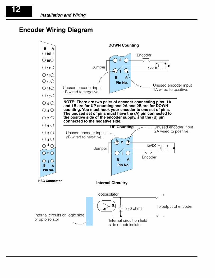
Installation and Wiring12
Encoder Wiring Diagram
AB
AB1
2
4
5
6
7
8
9
10
11
12
13
14
15
16
Pin No.
HSC Connector
3
DOWN Counting
AB
1
2
Pin No.
UP Counting
AB
1
2
Pin No.
330 ohms
optoisolator
Internal Circuitry
Jumper
Jumper
Encoder
Encoder
To output of encoder
+
--
+
+
--
--
NOTE: There are two pairs of encoder connecting pins. 1Aand 1B are for UP counting and 2A and 2B are for DOWNcounting. You must hook your encoder to one set of pins.The unused set of pins must have the (A) pin connected tothe positive side of the encoder supply, and the (B) pinconnected to the negative side.
Unused encoder input1A wired to positive.
Unused encoder input2A wired to positive.
12VDC
12VDC
Internal circuits on logic sideof optoisolator Internal circuit on field
side of optoisolator
Unused encoder input1B wired to negative.
Unused encoder input2B wired to negative.

Installation and Wiring1313
Output Wiring Diagram
AB
AB1
2
4
5
6
7
8
9
10
11
12
13
14
15
16
Pin No.
HSC Connector
3
Internal Circuitry
Internal circuits on logic sideof optoisolator
B A
16
5
4
3
Load
Load
5 or 24 VDC
V1+
5 or 24 VDC
Load
V1+
V1--
V1+
V1--
16A
3A, 4A, or 5A
NOTE: Pins 3, 4 and 5 are internally connected. Any one ofthese pins can be used for the supply wiring.
Optoisolator
Internal circuit on fieldside of optoisolator
3B, 4B, or 5B

Installation and Wiring14
Reset Wiring Diagram
AB1
2
4
5
6
Pin No.
HSC Connector
3
Internal Circuitry
AB
7
8
9
10
11
12
13
14
15
16
B A
6
330 ohms
optoisolator +
--Internal circuits on logic sideof optoisolator Internal circuit on field
side of optoisolator
+
--5 or 12 VDC

Installation and Wiring1515
BCD OutputsThe CPU cannot read the current count directly, but there are 16 BCD outputs fordriving a BCD display or connecting to a DC input module to read the current countinto the CPU. The 16-connecting points (7A&B thru 14A&B) are attached to the BCDinput of the drivers for visually displaying the BCD value or you can wire them to aninput module. Such a configuration is completely optional, and requires that yousupply the external devices. You determine the voltage level of these 16 pointsthrough your choice of an external power supply with the positive side connected topoints 3A, 4A, 5A, and negative side connected to 3B, 4B, and 5B.
User--Supplied Display Circuit
123
4
0
5
6
7
8
9
1011
1213
1415
AB
AB
1
2
3
4
5
6
7
8
9
10
11
12
13
14
15
16
Pin No.
Bit No.Thousands
Hundreds
Tens
Units
1248
10204080
100200400800
1000200040008000
HSC Connector
Example Interface for BCD Output of Current Count Value to LED Display
5 or 12 VDC+
--
Drivers LEDs
BCD Output Circuit (For Interfacing Display Device or Input Module)
Photocoupler10K
V1
InternalPower
SourcingSinking
Photocoupler
10K
Load
Load
V1--
NegativeLogic Positive
Logic
V1--
V1+V1+
Note:Pins 3, 4 and 5are internallyconnected.

Installation and Wiring16
I/O SpecificationsInput Specifications Count Input Reset Input
Minimum Input Pulse Width 25 µs 100 µs
Signal Direction Falling Edge ON
Power Source Voltage 12 VDC 10% 12 VDC 10%
ON Current 10--25 mA 10--25 mA
OFF Current 3 mA max. 3 mA max.
ON Voltage 7 V min. 7 V min.
OFF Voltage 3 V max. 3 V max.
BCD Output Specifications 5 V ¦ 5% 12V ¦ 10%
Current Consumption 10 mA max. 25 mA max.
Ripple 1% max. 3% max.
Output Current (source) (6.0 V) 0.1 mA 0.4 mA
External Output Specifications Rating
Output Type NPN Open Collector
Output Voltage 5--24 VDC
Output Current 0.3 A
Leakage Current 0.05 mA max.

Writing the Program1717
Writing the Program
You can write your PLC program by using acomputer with DirectSOFT programmingsoftware, or using a handheld programmercompatible with your particular model ofCPU.
Program-ming viaComputer
HandheldProgram-mer
DL305
HSC
The HSC must be set up with your ladder logic in a specified manner. If you are usingthe counters only (and not the external outputs), then you only have to worry aboutsetting up the counters:D Setup the Counters -- Your logic must setup a current count value (C) and a
preset value (P) in the same scan cycle. The order of execution must becurrent count first and preset second. The values used for either C or P canbe any integer between 0 and 9999. A value must be entered--there are nodefault values.
D Setup the Outputs (Optional) -- If you plan to use the external outputs, you mustsetup something called Output Mode and Output Logic Control for each of the twooutputs. These two settings will ultimately control the logic status (OFF or ON) andthe method for triggering each output.
Do youwant counting
only?
Stop!No need to setMode or theLogic Control
Do youwant the counterto automatically
control theoutput?
Whatoutput statusdo you wantwhen C< P?
Whatoutput statusdo you want?
Set OutputLogic=0
Set OutputLogic=1 Set Output
Logic=1Set OutputLogic=0
YES!
NO!
OFF!ON!
ON!OFF!
Output=ON Output=OFFOutput=OFFOutput=ON
(Mode=1) (Mode=0)AUTOMATIC MANUAL
Setup Current Count Setup Preset
YES! NO!
when C= P when C= P
Start
Immediately Immediatelyand C> P and C> P
How to Enter YourProgram:
Setup Procedure
Flow Diagram ofSetupLogic

Writing Your Program18
Setting Up the Counters
As mentioned earlier, you can use either a handheld programmer or DirectSOFT toenter your ladder logic. The examples we will be giving in this section of the manualare specific to DirectSOFT. We will, however, where necessary point out somesubtle differences for the handheld programmer. When setting up your counters, youwill be using the following conventions:D Instructions -- You will not be using the normal counter box when setting up the
HSC. While in DirectSOFT, if you use hot key F7 and examine the list of boxesavailable, you will find that one of them is called HSC. This is the box that you use inyour ladder logic for setting up the HSC. If you are using the handheld programmerfor the DL305, you will use the conventional CNT key (followed by the appropriatecounter number) in order to do the setup.
D Registers or Constants -- In order to setup the current count and preset inyour counters, you can either enter constant values directly (i.e. K125) or youcan point to any user-register (i.e. R400 ) where the values are stored. This isentirely up to you. We have used the direct reference with a constant in all ofour examples.
D Activating the Setup -- the counter begins counting pulses as soon as the CPUenters the RUN mode and the setup logic is scanned. You can use any type ofpermissive contact to trigger the setup logic. The setup logic only has to be scannedone time to setup the preset and the current count starting point. Therefore, it isimportant to trigger the setup logic with a one--shot. (See the example below as tohow this is done.) If you don’t use a one-shot, the current count and preset setup willbe executed as long as the permissive contact is on. (It will look like the counter isn’tworking properly, but in reality your program is simply loading a current count onevery scan!)
Shown below is a table with the counter numbers that you will enter either in yourHSC box (when using DirectSOFT) or following your CTR command when using thehandheld programmer. Notice that the counter used depends on the modulelocation in the base.
Counter Setup Slot 0 Cntr Slot 1 Cntr Slot 2 Cntr Slot 3 Cntr
Current Count CT100 CT102 CT104 CT106
Preset CT101 CT103 CT105 CT107
Example: The following ladder logic initializes an HSC in Slot 0 with a preset value of 125and a current count of 0. Notice the OUT RST instruction. In the DL305 instruction set, theOUT RST is a one-shot, similar to the PD (positive differential) instruction of the DL205 andDL405 families.
Start Setup
Setup One--Shot
Setup CurrentCountLoad 0 into cur-rent count counter
Setup PresetLoad 125 into
preset counter
CT100K0
HSC
HSCCT101K125
C160
IO120 C160OUT RST
ProgrammingConventions
Preset and CurrentCount

Writing the Program1919
The relationship between current count and preset will change as your program runsand the HSC continues to count pulses. You can monitor the status of C<P, C=P, andC>P by checking certain I/O points. Each of the three flags have I/O points assignedto them for storing the status of each. The addresses associated with these pointschanges according to which slot you have used for the HSC. You can use the I/Opoints for these flags to trigger events inside your RLL program.
Counter Status Slot 0 Slot 1 Slot 2 Slot 3
C >P IO000 IO010 IO020 IO030
C = P IO001 IO011 IO021 IO031
C < P IO002 IO012 IO022 IO032
Example: The following ladder logic will turn ON an indicataor lamp when C = P for an HSCin Slot2.
OUT
C = P
Turn ON indicator lamp.
Setup of HSC precedes this section of code.
IO150IO021
The upper limit for the counter is 9999. If your ladder logic has been written so thatthe counter continues to count past C=P and eventually reach a current count of9999, the counter will stop counting pulses when it reaches the upper limit. It doesnot wrap around to zero. It is instead in an “overflow” status.
The I/O point assigned to the Overflow function (current count greater than 9999range) of the HSC can also be monitored by your RLL to either report the status ortrigger an event. The address associated with the I/O point changes according toHSC slot position and is shown in the following table:
Counter Overflow Slot 0 Slot 1 Slot 2 Slot 3
Count > 9999 IO003 IO013 IO023 IO033
Example: The following ladder logic will sound an alarm if the current countexceeds 9999. This example assumes the HSC is in Slot 0.
Overflow relay
Turn On Alarm connected at IO140
Setup of HSC precedes this section of code.
OUT
IO140IO003
RelationshipBetween Preset andCurrent Count
What Happens Afterthe Counter Reachesthe Upper Limit?
Overflow

Writing Your Program20
Setting Up the Outputs
You use your ladder logic to select the way that the HSC outputs operate. You willuse your logic to turn ON or OFF certain internal I/O points that control what arecalled Output Mode and Output Logic Control. By controlling the mode and logicfor Outputs1 and 2, we are able to determine when the outputs turn ON or OFF. Theflow diagram shown below explains the thought process for setting the mode andlogic control to determine the status of the outputs. For example, if you choose tooperate OUTPUT1 in the automatic mode, and you want to have the output ONwhen current count is less thant preset (C < P), then you will want to set Output1Mode = 1 and set Output1 Logic Control = 1.
Do youwant the counterto automatically
control theoutput?
Whatoutput statusdo you wantwhen C< P?
Whatoutput statusdo you want?
Set OutputLogic=0
Set OutputLogic=1 Set Output
Logic=1Set OutputLogic=0
OFF!ON!
ON!OFF!
Output=ON Output=OFFOutput=OFFOutput=ON
(Mode=1) (Mode=0)AUTOMATIC MANUAL
YES! NO!
when C= P when C= P Immediately Immediately
It may be also useful to look at the relationship between the Output Mode and OutputLogic control and the external outputs for C < P and C = P using a table.
Output 1 Mode Output 1 LogicControl
Output 1C < P
Output 1C = P
1 0 OFF ON
1 1 ON OFFOutput 2 Mode Output 2 Logic
ControlOutput 2
C < POutput 2
C = P
1 0 OFF ON
1 1 ON OFF
NOTE: When in the Automatic Mode (Output Mode = 1), the output will assume thestate determined by the output logic control as soon as the CPU is placed into theRun Mode.
How to Control TheOutputs:
Flow Diagram ofSetupLogic
Table 1Status of Mode andLogic Controls in theAutomatic Mode

Writing the Program2121
The table shown below will help you determine the appropriate internal I/O points forselecting the Mode and Output Logic Control associated with the two outputs of theHSC. Remember the HSC can go into Slots 0, 1, 2 or 3. The numbers associatedwith the I/O points change depending on which slot you have selected.
CPU Output Reference Slot 0 Slot 1 Slot 2 Slot 3
Output 1 Mode IO100 IO110 IO120 IO130
Output 1 Logic Control IO101 IO111 IO121 IO131
Output 2 Mode IO102 IO112 IO122 IO132
Output 2 Logic Control IO103 IO113 IO123 IO133
Example: The following example shows how to set up an HSC installed in Slot 1 toautomatically control the outputs. You want both outputs to be ON when the PLC isplaced in RUN (C<P), but turn OFF when C=P. The table shows IO110--IO113 forSlot1. If we follow the flow chart, we see that we need to turn ON IO110--IO113, whichselects the automatic mode for both outputs and the C=P operation to go from ON toOFF.
Start Setup
Setup One--Shot
Output 1 Mode= 1 (Automatic)
Output 2 Mode= 1 (Automatic)
Output 1 Logic Control = 1
Output 2 Logic Control= 1
OUT RST
C160SET
IO020 C160
SET
SET
SET
IO110
IO111
IO112
IO113
When using the automatic mode (as shown above), the state of Output 1 LogicControl and Output 2 Logic Control determines the state of Output1 and Output2until C = P. So in the above example, both outputs will turn ON as soon as the PLCenters RUN mode. These outputs will remain ON until enough pulses have beencounted for current count to equal preset (C = P).The example below, uses the RST command to set the Mode to manual and it usesthe OUT command to control the Logic Controls for the two outputs IO21 and IO22.
Start Setup
Setup One--Shot
Output 1 Mode= 0 (Manual)
Output 2 Mode= 0 (Manual)
IO21 and IO22 are inputs from a disc-trete input module installed in Slot 2.Output1 will follow the status of IO21.Output2 will follow the status of IO22.
IO21
IO22
OUT RST
C160RST
IO020 C160
RST
OUT
OUT
IO110
IO111
IO112
IO113
Setting Mode andOutput Logic Control

Putting It All Together22
Example 1:Activating both Outputs Automatically
Set Output1 Mode=Automatic (1)
Set Output2 Mode=Automatic(1)
Set Output1 Logic = 1
Setup One--Shot
Setup CurrentCountLoad 0 into cur-rent count counter
Setup PresetLoad 20 into
preset counter
HSC
HSC
CT102
CT103
K0
K20
Start Switch
One-Shot
Set Output2 Logic = 1
END
The core of your program goes here.
As you know from reading earlierpages, the HSC module can go in slots0,1, 2, or 3. In this program, we areassuming that the HSC module hasbeen placed in Slot 1. This means thatthe counters (HSC boxes) in yourprogram would be designated asCT102 and CT103 (See Page 16). TheOutput Mode and Output Logic controlare assigned I/O points 110 through113 (See Page 19).
We are using IO0 and C160 as aone-shot to start this setup.Theone-shot enables the two HSC boxes,CT102 and CT103 for one scan. Thisinitializes the preset value to 20 andthe current count to 0.
C160 also turns ON IO111 and IO113,enabling the Automatic Mode for bothoutputs. This means when each outputwill turn ON or OFF is solely dependenton the current count and preset. WhenC = P, OUTPUT1 and OUTPUT2 willbe activated. Whether this meanseither output turns ON or OFF,depends on how you have set theOutput Logic Control in each case.Here you see that we have set thelogic of both to 1. So, this means thatthe output will be ON when C < P andturn OFF when C = P.
OUT RST
C160
SET
C160
SET
SET
SETIO110
IO111
IO112
IO113
C160
IO0

Putting It All Together2323
Example 2:Mixing Modes of Operation for Outputs
C160 IO111SET
IO113
IO11
RST
C162
IO110SET
Set internal relayC162 when cur-rent count equalspreset.
Set Output1 Mode = Automatic (1)
Set Output2 Mode=Manual (0)
Set Output1 Logic = 1
OUT RST
C160
IO0 C160
Setup One--Shot
Setup CurrentCountLoad 0 into cur-rent count counterSetup PresetLoad 20 into
preset counter
HSC
HSC
CT102
CT103
K0
K20
SET
TMRT600K10
C162
T600 IO112SET When T600 times
out, turn ONOUTPUT2 and resetthe timer.
Start Switch
One-Shot
Turns ON when C = P
C = P
Start timer that willrun for one se-cond.
In this example, we are illustrating howyou can use the manual and automaticmodes for controlling outputs in thesame program. We have decided tocontrol OUTPUT1 automatically, andto control OUTPUT2 manually. Thiscould be a cut-to-length applicationwhere OUTPUT1 advances a boardtoward a saw for a preset number ofpulses recorded by the HSC. OUT-PUT2 controls the cutting operation.We will assume the HSC module is inSlot 1.
When C = P, OUTPUT1 is turned OFF.At the same time, relay C162 turns ona timer (T600). When T600 times out,we turn ON OUTPUT2 by settingIO112. In our board cutting example,this could mean that a saw is activatedby OUTPUT2. The point being madehere is that manual control of anoutput or outputs operatesindependently from the status ofpreset and current count.
In the Manual Mode, the relationshipof current count compared to presetdoes not automatically affect the out-put. In the example shown here, wehave used an internal status flag relayIO11 (C=P) to start a timer. When thetimer times out(1 second), we turn ONOUTPUT2 by setting IO112. This isdone to insure the board has stoppedmoving before we start the cut.
END
The core of your program goes here.
C162RST
IO1 IO112RST When cut is com-
plete, turn OFFOUTPUT2.
Cut Complete

Putting It All Together24
Example 3: Changing Presets On the Fly
WARNING: The application shown below changes the counter’s preset value whilethe program is executing. Under some conditions (explained in a moment), thiscauses OUTPUT1 and OUTPUT2 to turn ON for approximately 1 millisecond assoon as preset is changed. This condition occurs only if the external outputs are OFFwhen the change is initiated, and you are in the automatic mode of control. Thiscould result in unsafe or unpredictable results if the field device connected to theoutputs sees this momentary ON signal. To prevent this, include a segment in yourladder logic that switches the operating mode of the HSC to manual before thepreset is changed. The example below illustrates how this is done.
Load HSC Current Count
C162 C165
OUTRST Disable Load Using One-shot
OUT
C162
IO002 C161
Configure HSC
Current CountValue Set to 0
Preset Value Setto 200
HSC
HSC
CT102
CT103
K0
K200
Load New PresetIn this example, we are illustrating howyou can change the preset value “on thefly”. This means you are changing thepreset while the program is still running.Although we are only showing the logic forcontrolling OUTPUT1, the same methodcould be used to affect both outputs.
We have placed the HSC in Slot 1 for thisexample. It can, of course, go into any Slot0 through 3. We will assume at the point inin your program where this logic starts, theprocess has been running with a Presetthat had been entered in earlier ladderlogic not shown here. At the point thisladder logic is executed, the counter hasalready been counting pulses andcomparing them against the previousPreset.
This part of the program uses an MCS andMCR instruction to load a new CurrentCount and Preset value. The logicbetween MCS and MCR will only executewhen the MCS rung has power flow.
With this example, the process is startedvia IO002. When energized, C161 islatched in the ON state. C161 also enablesthe MCS. C161 resets IO111, putting theHSC in Manual Mode. The only other rungthat executes during this first scan is therung that causes C161 to turn ON C162.
On the second scan through the logicinside the MCS/MCR, since C162 is nowON, CT102 loads a new Current Count of0 and CT103 writes a new Preset of 200.C162 will one-shot C165, which puts theHSC back into autmatic mode and resetsIO110. It also disables the MCS/MCR.
End logic under MCSand MCR Control
MCR
C161Configure HSC
C165Disable Load
C161
MCS
Configure HSC
IO111
RST
C162Load HSC Preset
C161 C162
OUTLoad HSC CurrentCount and Preset
C165
SET Set Output1 Mode =1 (automatic)
Disable Load
IO110
RST Output 1 Logic Control=0
IO111
END
C161Configure HSC
Set Output1 Mode =0 (manual)
Configure HSC


