D2.5 – Development of reliability test procedures for … · D2.5 – Development of reliability...
41
Public Electric Vehicle Enhanced Range, Lifetime And Safety Through INGenious battery management D2.5 – Development of reliability test procedures for EV BMS February 2018 This project has received funding from the European Union’s Horizon 2020 research and innovation programme under grant agreement No 713771
-
Upload
nguyenhanh -
Category
Documents
-
view
219 -
download
0
Transcript of D2.5 – Development of reliability test procedures for … · D2.5 – Development of reliability...

Public
Electric Vehicle Enhanced Range, Lifetime And Safety Through INGenious battery management
D2.5 – Development of reliability test procedures for EV BMS
February 2018
This project has received funding from the European Union’s Horizon 2020 research and innovation programme under grant agreement No 713771

D2.5 – Development of reliability test procedures for EV BMS
Author: Alexander Stadler (TUV SUD)– Feb. 2018
EVERLASTING - Grant Agreement 71377 (Call: H2020-GV8-2015) Electric Vehicle Enhanced Range, Lifetime And Safety Through INGenious battery management
Public 2 / 41
PROJECT SHEET
Project Acronym EVERLASTING
Project Full Title Electric Vehicle Enhanced Range, Lifetime And Safety Through INGenious battery management
Grant Agreement 713771
Call Identifier H2020-GV8-2015
Topic GV-8-2015: Electric vehicles’ enhanced performance and integration into the transport system and the grid
Type of Action Research and Innovation action
Project Duration 48 months (01/09/2016 – 31/08/2020)
Coordinator VLAAMSE INSTELLING VOOR TECHNOLOGISCH ONDERZOEK NV (BE) - VITO
Consortium Partners
COMMISSARIAT A L ENERGIE ATOMIQUE ET AUX ENERGIES ALTERNATIVES (FR) - CEA SIEMENS INDUSTRY SOFTWARE SAS (FR) - Siemens PLM TECHNISCHE UNIVERSITAET MUENCHEN (DE) - TUM TUV SUD BATTERY TESTING GMBH (DE) - TUV SUD ALGOLION LTD (IL) - ALGOLION LTD RHEINISCH-WESTFAELISCHE TECHNISCHE HOCHSCHULE AACHEN (DE) - RWTH AACHEN LION SMART GMBH (DE) - LION SMART TECHNISCHE UNIVERSITEIT EINDHOVEN (NL) - TU/E VOLTIA AS (SK) - VOLTIA VDL ENABLING TRANSPORT SOLUTIONS (NL) – VDL ETS
Website www.everlasting-project.eu

D2.5 – Development of reliability test procedures for EV BMS
Author: Alexander Stadler (TUV SUD)– Feb. 2018
EVERLASTING - Grant Agreement 71377 (Call: H2020-GV8-2015) Electric Vehicle Enhanced Range, Lifetime And Safety Through INGenious battery management
Public 3 / 41
DELIVERABLE SHEET
Title D2.5 – Development of reliability test procedures for EV BMS
Related WP WP2 (Increased reliability)
Lead Beneficiary TUV SUD
Author(s) Alexander Stadler (TUV SUD) Thore Klink (TUV SUD)
Reviewer(s) Javier Muñoz Alvarez (LION Smart) Levin Hennig (LION Smart) Klaas De Craemer (VITO)
Type Report
Dissemination level PUBLIC
Due Date M18
Submission date February 28, 2018
Status and Version Peer reviewed version V1.0

D2.5 – Development of reliability test procedures for EV BMS
Author: Alexander Stadler (TUV SUD)– Feb. 2018
EVERLASTING - Grant Agreement 71377 (Call: H2020-GV8-2015) Electric Vehicle Enhanced Range, Lifetime And Safety Through INGenious battery management
Public 4 / 41
REVISION HISTORY
Version Date Author/Reviewer Notes
V0.1 14/02/2018 Alexander Stadler (TÜV SÜD) Lead Beneficiary
First draft for review
V0.2 26/02/2018 Alexander Stadler (TÜV SÜD) Javier Muñoz Alvarez (LION Smart) Levin Hennig (LION Smart) Klaas De Craemer (VITO)
Reviewed by partners
V1.0 28/02/2018 Carlo Mol (VITO) Coordinator
Submission to the EC

D2.5 – Development of reliability test procedures for EV BMS
Author: Alexander Stadler (TUV SUD)– Feb. 2018
EVERLASTING - Grant Agreement 71377 (Call: H2020-GV8-2015) Electric Vehicle Enhanced Range, Lifetime And Safety Through INGenious battery management
Public 5 / 41
DISCLAIMER The opinion stated in this report reflects the opinion of the authors and not the opinion of the European Commission. All intellectual property rights are owned by the EVERLASTING consortium members and are protected by the applicable laws. Except where otherwise specified, all document contents are: “© EVERLASTING Project - All rights reserved”. Reproduction is not authorised without prior written agreement. The commercial use of any information contained in this document may require a license from the owner of that information. All EVERLASTING consortium members are committed to publish accurate information and take the greatest care to do so. However, the EVERLASTING consortium members cannot accept liability for any inaccuracies or omissions nor do they accept liability for any direct, indirect, special, consequential or other losses or damages of any kind arising out of the use of this information. ACKNOWLEDGEMENT This project has received funding from the European Union’s Horizon 2020 research and innovation programme under grant agreement No 713771

D2.5 – Development of reliability test procedures for EV BMS
Author: Alexander Stadler (TUV SUD)– Feb. 2018
EVERLASTING - Grant Agreement 71377 (Call: H2020-GV8-2015) Electric Vehicle Enhanced Range, Lifetime And Safety Through INGenious battery management
Public 6 / 41
EXECUTIVE SUMMARY
This report proposes dedicated test cases for testing a Battery Management System independently from the full battery system. The first chapter defines the functional, performance and safety requirements that shall be defined and provided by the BMS manufacturer. If the in the following proposed tests cannot validate these requirements, additional test cases need to be developed to verify the BMS. Furthermore, a possible test setup is proposed, including a general classification of modes of operation and functional statuses. In chapter two, the different tests are defined, categorized in environmental tests, functional and safety tests, electrical tests, and evaluation of SoC und SoH performance.

D2.5 – Development of reliability test procedures for EV BMS
Author: Alexander Stadler (TUV SUD)– Feb. 2018
EVERLASTING - Grant Agreement 71377 (Call: H2020-GV8-2015) Electric Vehicle Enhanced Range, Lifetime And Safety Through INGenious battery management
Public 7 / 41
TABLE OF CONTENTS
EXECUTIVE SUMMARY ........................................................................................................ 6 TABLE OF CONTENTS .......................................................................................................... 7 LIST OF ABBREVIATIONS AND ACRONYMS ......................................................................... 8 LIST OF FIGURES ................................................................................................................ 8 LIST OF TABLES .................................................................................................................. 8 INTRODUCTION .................................................................................................................. 9 1 DEFINITION OF DEVICE UNDER TEST AND CRITERIA ................................................... 9
1.1 DEFINITION OF BMS FUNCTIONALITY AND SAFETY REQUIREMENTS .................................................. 9 1.2 DEFINITION OF TEST SAMPLE ............................................................................................. 9 1.3 DEFINITION OF OPERATING MODES AND TEST CRITERIA ............................................................ 13 1.4 LIST OF TESTS ............................................................................................................ 14
2 TEST DEFINITION ....................................................................................................... 15 2.1 ENVIRONMENTAL TESTS .................................................................................................. 17
2.1.1 Initial temperature cycling ................................................................................... 17 2.1.2 Rapid temperature change ................................................................................... 18 2.1.3 Mechanical shocks .............................................................................................. 19 2.1.4 Mechanical vibration ........................................................................................... 20
2.2 FUNCTIONAL AND SAFETY TESTS ....................................................................................... 22 2.2.1 Detection and Protection against battery overcharging ............................................ 22 2.2.2 Detection and Protection against battery over discharging ....................................... 23 2.2.3 Detection and Protection against single cell over and under voltage .......................... 24 2.2.4 Detection and Protection against overcurrent ......................................................... 25 2.2.5 Detection of a short circuit ................................................................................... 26 2.2.6 Measurement of temperatures and protection against overuse ................................. 27 2.2.7 Detection of insulation faults ................................................................................ 28 2.2.8 Test of pre-charge interlock functions .................................................................... 29 2.2.9 Functional behavior for full temperature range ....................................................... 30
2.3 ELECTRICAL TESTS........................................................................................................ 31 2.4 EVALUATION OF SOC & SOH PERFORMANCE ......................................................................... 32
2.4.1 Determining SoC estimation performance .............................................................. 33 2.4.2 Determining SoH estimation performance .............................................................. 36
CONCLUSIONS .................................................................................................................. 40 REFERENCES ..................................................................................................................... 41
D2.5 – Development of reliability test procedures for EV BMS
Author: Alexander Stadler (TUV SUD)– Feb. 2018
EVERLASTING - Grant Agreement 71377 (Call: H2020-GV8-2015) Electric Vehicle Enhanced Range, Lifetime And Safety Through INGenious battery management
Public 8 / 41
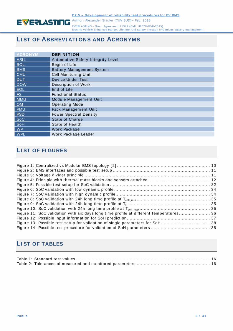
LIST OF ABBREVIATIONS AND ACRONYMS
ACRONYM DEFINITION ASIL Automotive Safety Integrity Level BOL Begin of Life BMS Battery Management System CMU Cell Monitoring Unit DUT Device Under Test DOW Description of Work EOL End of Life FS Functional Status MMU Module Management Unit OM Operating Mode PMU Pack Management Unit PSD Power Spectral Density SoC State of Charge SoH State of Health WP Work Package WPL Work Package Leader
LIST OF FIGURES
Figure 1: Centralized vs Modular BMS topology [2] .................................................................. 10 Figure 2: BMS interfaces and possible test setup ..................................................................... 11 Figure 3: Voltage divider principle ......................................................................................... 11 Figure 4: Principle with thermal mass blocks and sensors attached ............................................ 12 Figure 5: Possible test setup for SoC validation ....................................................................... 32 Figure 6: SoC validation with low dynamic profile .................................................................... 34 Figure 7: SoC validation with high dynamic profile ................................................................... 34 Figure 8: SoC validation with 24h long time profile at Tcell_min .................................................... 35 Figure 9: SoC validation with 24h long time profile at TRT ......................................................... 35 Figure 10: SoC validation with 24h long time profile at Tcell_max .................................................. 35 Figure 11: SoC validation with six days long time profile at different temperatures ...................... 36 Figure 12: Possible input information for SoH prediction ........................................................... 37 Figure 13: Possible test setup for validation of single parameters for SoH ................................... 38 Figure 14: Possible test procedure for validation of SoH parameters .......................................... 38
LIST OF TABLES
Table 1: Standard test values ............................................................................................... 16 Table 2: Tolerances of measured and monitored parameters .................................................... 16

D2.5 – Development of reliability test procedures for EV BMS
Author: Alexander Stadler (TUV SUD)– Feb. 2018
EVERLASTING - Grant Agreement 71377 (Call: H2020-GV8-2015) Electric Vehicle Enhanced Range, Lifetime And Safety Through INGenious battery management
Public 9 / 41
INTRODUCTION
A Battery Management Systems (BMS) is a key component of a battery system, in charge of monitoring, controlling and protecting the battery system and the single cells. Due to its importance for the overall battery safety and performance, many of the final tests done on a complete battery system depend on the correct performance of the BMS. Final certification and homologation tests for EV batteries are done on complete systems as they are intended to be used in the vehicle. Tests on such batteries are expensive in terms of testing cost, as well as considering the cost of producing the necessary samples, especially when using prototypes. The aim of this document is to define different test scenarios and their corresponding pass/fail or performance criteria on BMS level in order to properly evaluate a BMS system and to avoid the high cost of testing a full battery system. Also, such tests would give the possibility for manufacturers and users to assess the quality of a BMS in relation to the intended use. In a next step in the EVERLASTING project, the defined tests will be applied to a prototype BMS, supplied by the project partner LION Smart GmbH in order to validate and refine the defined test cases.
1 DEFINITION OF DEVICE UNDER TEST AND CRITERIA
1.1 DEFINITION OF BMS FUNCTIONALITY AND SAFETY REQUIREMENTS
During the design process of a BMS system, the manufacturer will define certain performance and safety aspects to be fulfilled. Additionally, the manufacturer should assess the BMS according to ISO 26262, in order to identify additional safety requirements and their ASIL (Automotive Safety Integrity Level) rating. This set of functional, performance and safety requirements will be compiled into the requirement specification for the battery application, which the BMS system will be used in. This makes it difficult to fully define all required tests in a general approach applicable for all BMS systems. Therefore, it is important to include the manufacturers defined functional, performance and safety requirements in any analysis of the BMS reliability and functionality. Prior to testing, the manufacturer will have to supply all the required documentation to operate the BMS and to assess its functionality and the expected behavior. In this document, a basic set of tests and their corresponding minimal pass/fail criteria will be outlined. However, depending on the design characteristics of a BMS system, it is important to include the requirements of the BMS manufacturer to define additional criteria for each test. Also, it is advisable to derive additional test scenarios for essential functionalities of the BMS where necessary.
1.2 DEFINITION OF TEST SAMPLE
BMS architectures can be differentiated into centralized, modular and distributed systems. A brief technical overview has been given in the EVERLASTING deliverable “D6.1–Analysis of the state of the art on BMS” [1].

D2.5 – Development of reliability test procedures for EV BMS
Author: Alexander Stadler (TUV SUD)– Feb. 2018
EVERLASTING - Grant Agreement 71377 (Call: H2020-GV8-2015) Electric Vehicle Enhanced Range, Lifetime And Safety Through INGenious battery management
Public 10 / 41
Figure 1: Centralized vs Modular BMS topology [2]
Each BMS has a considerable number of in- and output signals. Typical interfaces are shown in Figure 2.
• Cell voltages of single cells or cells in parallel (Macrocells); o Currently, the EVERLASTING demonstrator is planned with 192 cells in series.
Therefore the BMS will have 192 voltage signals; • Battery voltage and voltage of a pre-charge connection;
o Typically, before connecting the battery to the load by closing the main contactors, a pre-charge of the load circuits is done via a dedicated contactor and a certain resistance in series. This allows to slowly charge the load circuits to the battery voltage to avoid current peaks when switching the battery on. The rise of the pre-charge voltage over time is usually monitored to verify the integrity of the load circuit;
• Cell temperatures of reference cells; o The EVERLASTING BMS is planned with at least 96 temperature sensors distributed
throughout the different cells in the battery pack; • Current sensors for at least the battery current, sometimes additional current sensors on
modules; • An insulation monitoring system;
o Monitoring the insulation resistance between both battery terminals and the ground of the battery casing;
• Additional sensors, if applicable; o Temperature sensors monitoring temperatures of the electronics, temperatures of
cooling plates or fluids; o Sometimes new sensor technologies to determine SoC and SoH.

D2.5 – Development of reliability test procedures for EV BMS
Author: Alexander Stadler (TUV SUD)– Feb. 2018
EVERLASTING - Grant Agreement 71377 (Call: H2020-GV8-2015) Electric Vehicle Enhanced Range, Lifetime And Safety Through INGenious battery management
Public 11 / 41
Figure 2: BMS interfaces and possible test setup
In order to simulate a complete battery environment for a full scale BMS, a considerable number of signals needs to be generated and controlled. There are different ways to simulate cell voltages and temperatures. The final setup will depend on the BMS architecture and must be defined on a case by case basis. The following principles could be used:
• Generating cell voltages based on a voltage divider principle (Figure 3); o The virtual cell voltages can be simultaneously raised and lowered by varying the total
voltage; o Variations in single cell voltages can be archived by using variable resistors;
• Simulating a stable temperature environment by using an adequate thermal mass to place the sensors on;
o By using separate mass blocks different temperatures can be simulated (Figure 4); • Using a low voltage high current power supply to generate a noticeable current for the main
battery current sensor.
Figure 3: Voltage divider principle

D2.5 – Development of reliability test procedures for EV BMS
Author: Alexander Stadler (TUV SUD)– Feb. 2018
EVERLASTING - Grant Agreement 71377 (Call: H2020-GV8-2015) Electric Vehicle Enhanced Range, Lifetime And Safety Through INGenious battery management
Public 12 / 41
Figure 4: Principle with thermal mass blocks and sensors attached
Due to the big number of interfaces for the EVERLASTING BMS, defining a mock-up as a Device Under Test (DUT) of the BMS with reduced input/output signals may be more efficient for testing. On the one hand, a mock-up will provide various advantages:
• Reduced number of generated voltage signals to simulate BMS operation; o For smaller BMS systems it might be thinkable to reduce the number of simulated cell
voltages to 13, which will allow to stay below 60V (approx. 4,3V*13) when setting up the test rig. Voltages below 60V are classified as low-voltage and do not require additional safety precautions and specially trained staff;
o For EV BMS systems, a reduction of voltage signals will reduce the effort and cost to design and build the setup. Even if the used voltage will exceed 60V, it can be limited to a level where the high voltage safety aspects are less severe;
• Reduced number of temperature readings; o A reduction of sensors would result in easier handling and reduce the required cost for
handling; • In general, it will allow for reduced efforts and cost to perform the defined tests. This will
enable for simple and cost-effective testing, which can motivate more BMS suppliers to test their systems independently from the final battery systems;
On the other hand, the required modification on software and hardware level for a mock-up will significantly change the BMS to be tested. If the modifications are done by e.g. reducing the number of slaves or deactivation a number input ports, the changes would also require software modifications. Furthermore, a reduction of slaves or input ports will influence the timing behavior of the communication and internal computing of the BMS. Therefore, it is challenging to provide proof that the test results of the mock-up will represent the tests on a full scale BMS. However, if the manufacturer is confident, that the software modifications will not affect the overall functionality of the BMS, the observed test results on a mock-up can still give an indication about the expected results on battery level at reduced costs. Some of the environmental tests, e.g. temperature shocks, aim on testing primarily the hardware, those tests are also not significantly affected by software modification. However, timing relevant aspects of the BMS performance will very likely be falsified by a smaller mock-up. In Conclusion, testing a BMS on a mock-up scale can be useful to reduce test cost and effort. However, it must be carefully decided by the manufacturer of the BMS if the test results are reliable enough to serve their intended purpose, e.g. indicative pre-tests, or if necessary to provide a formal proof of fulfilling a safety requirement, which will not be checked again in later tests on full battery level. In this case, tests on a mock-up are not recommended.

D2.5 – Development of reliability test procedures for EV BMS
Author: Alexander Stadler (TUV SUD)– Feb. 2018
EVERLASTING - Grant Agreement 71377 (Call: H2020-GV8-2015) Electric Vehicle Enhanced Range, Lifetime And Safety Through INGenious battery management
Public 13 / 41
1.3 DEFINITION OF OPERATING MODES AND TEST CRITERIA
For each test to be conducted, the operating mode of the DUT must be defined. Some tests, e.g. temperature cycling tests, do not require the system to be operational. For other tests, it is vital to be fully operational, e.g. contactors closed and current flowing. There are different industrial standards, defining Operating Modes (OM) for automotive equipment. In order to take into account the operating situation of a battery in electrical vehicles the following definition will be used.
• Operating mode 1 o No supply voltage, DUT off
Operating mode 1.1: no wiring connected Operating mode 1.2: external wiring (e.g. supply voltage, communication,
interlocks) and internal wiring (e.g. sensors) connected. • Operating mode 2
o The DUT is electrically operated with all electrical connections made. Operating mode 2.1: DUT functions are not activated (e.g. sleep mode). Operating mode 2.2: DUT in electric operation and no HV-load. Operating mode 2.3: DUT in electric operation and with HV-load.
It is also important to define a Functional Status (FS) of the system during or after each test.
• Functional Status 1 o The BMS performs as intended during and after the test. No critical operation of the
battery system is allowed at any time. o Functional Status 1.1
Battery usage is not limited or affected. o Functional Status 1.2
Battery usage limited or affected. Battery usage returns to normal operation if the battery is in a normal state and after the BMS is reset by a simple user action or an automated action of the vehicle.
o Functional Status 1.3 Battery usage limited or affected. Battery usage does not return to normal
operation without intervention of a qualified service personnel. • Functional Status 2
o One or more functions of the BMS do not perform as intended during the test, but no critical operation of the battery system is allowed at any time.
o Functional Status 2.1 Battery usage is not limited or affected.
o Functional Status 2.2 Battery usage limited or affected. Battery usage returns to normal operation if
the battery is in a normal state and after the BMS is reset by a simple user action or an automated action of the vehicle.
o Functional Status 2.3 Battery usage limited or affected. Battery usage does not return to normal
operation without intervention of qualified service personnel. • Functional Status 3
o One or more functions of the BMS do not perform as intended during the test, a critical operation of the battery cannot be safely prevented.
For each of the tests the required functional status will be defined. In case of unexpected deviations from the expected result, the manufacturer shall classify the test result and give a reasoning for the classification. Also, the manufacturer shall define additional criteria to demonstrate that the BMS will meet the defined specifications or safety requirements, where necessary. This should also include detailed information on timing (how fast should a certain reaction occur) and reaction (e.g. contactor status or CAN error messages). It shall also be defined, in which state and how the system shall recover after failure.
D2.5 – Development of reliability test procedures for EV BMS
Author: Alexander Stadler (TUV SUD)– Feb. 2018
EVERLASTING - Grant Agreement 71377 (Call: H2020-GV8-2015) Electric Vehicle Enhanced Range, Lifetime And Safety Through INGenious battery management
Public 14 / 41
1.4 LIST OF TESTS
The tests to be conducted on a BMS system can be grouped in the following categories: • Environmental tests • Functional and safety tests • Electrical tests
Environmental tests will include: • Functional tests at various temperature & humidity conditions • Vibration and shock tests
Functional and safety tests aim to verify the behavior of the BMS and its safety mechanisms in potentially dangerous situations. Also, the monitoring of relevant signals during normal operation will be verified. The following functionalities will be checked:
• Detection and protection against o Battery overcharging o Battery over-discharging o Single cell over- and under-voltage o Overcurrent
• Detection of a short circuit • Measurement of temperatures and protection against overuse • Detection of insulation faults • Pre-charge interlocks • Evaluation of SoC • Evaluation of SoH
Electrical tests will be used to check the robustness of the BMS against disturbances on external signal and power supply lanes. The tests will include:
• Electrical tests, verifying the functionality of the BMS in regard to the different requirements and possible operational situations in a low voltage on-board vehicle network
• insulation resistance and dielectric strength on vital BMS connectors and interfaces
The manufacturer shall define additional tests to demonstrate the fulfillment of prior identified safety requirements, if they have not been covered by other tests, yet. Any type of BMS will very likely be protected by an additional housing during assembly of the complete battery system. The BMS can either be included inside the housing of the battery system or be placed in a separate housing with feed-throughs and connections towards the main battery. The housing will protect the BMS against the effects of external humidity, water and dust. The degree of protection achieved is depending on the design of the housing and its seals. Additionally, the housing will shield the BMS from effects of external electromagnetic effects, and reduce the electromagnetic radiation. Therefore, the effects resulting from the housing cannot be tested on the BMS only. All tests which are strongly influenced by the presence of the housing, are therefore excluded from this test proposal:
• Test concerning humidity • Tests concerning dust and water tightness • Tests verifying the delayed access to high-voltage parts • Tests concerning electromagnetic radiation, immunity or coupling

D2.5 – Development of reliability test procedures for EV BMS
Author: Alexander Stadler (TUV SUD)– Feb. 2018
EVERLASTING - Grant Agreement 71377 (Call: H2020-GV8-2015) Electric Vehicle Enhanced Range, Lifetime And Safety Through INGenious battery management
Public 15 / 41
2 TEST DEFINITION
The defined tests are derived from the available battery testing standards and regulations with a focus on standards for EV batteries. The following standards have been used as a guideline and applicable tests have been extracted to test a BMS. The adaptation of the test cases has been done by using the experience and know-how of TÜV SÜD Battery Testing GmbH as testing laboratory.
• UN ECE R100 rev.2 – “Uniform provisions concerning the approval of vehicles with regard to specific requirements for the electric power train”
• ISO 12405-2 – “Electrically propelled road vehicles — Test specification for lithium-ion traction battery packs and systems — Part 2: High-energy applications
• ISO 12405-3 – “Electrically propelled road vehicles — Test specification for lithium-ion traction battery packs and systems — Part 3: Safety performance requirements
• IEC 62619:2017 – “Secondary cells and batteries containing alkaline or other non-acid electrolytes – Safety requirements for secondary lithium cells and batteries, for use in industrial applications”
• ISO 16750 – “Road vehicles — Environmental conditions and testing for electrical and electronic equipment”
In the following, the required standard test parameters will be defined. Some standards like ISO 16750 differentiate between supply voltages with the scenarios “generator off” and “generator on”. In a traditional combustion engine vehicle, this would imply approx. 12,6V and 14,4V (standard values for lead-acid batteries). Plugin-hybrid as well as electric vehicles in the near future will very likely still have separate batteries for a low-voltage supply. Low voltage supply batteries will then be charged via the generator (PHEV) or through a DC-DC converter (EV, HV-circuit operational). For a BMS, this distinction of operating states is not made. Instead, some of the tests proposed in this document will be done at different supply voltages, verifying the operational limits, defined by the manufacturer:
• Uop_min: Minimum operation voltage as specified by the manufacturer; • Uop_typ: Typical operation voltage as specified by the manufacturer; • Uop_max: Maximum operation voltage as specified by the manufacturer.
The following tests will be done at two different sets of temperatures. For tests using resistors simulating the cell voltages, the operational temperatures of the BMS shall be used. This will allow for testing the BMS at its limits, and because no real cells are used for the setup, the operational limits of the cells do not apply. However, for tests with simulated parameters that are based on temperature sensitive cell parameters, e.g. battery current, the BMS operational limits can be derived from the limits of the cells.
• TBMS_min Minimum operating temperature of the BMS as defined by the manufacturer • TRT Room temperature, 23°C • TBMS_max Maximum operating temperature of the BMS as defined by the manufacturer
For tests using real cells, the minimum and maximum temperatures shall be limited to a temperature range where the cell can be operated.
• Tcell_min Minimum operating temperature of the cell to be used with the BMS • TRT Room temperature, 23°C • Tcell_max Maximum operating temperature of the cell to be used with the BMS

D2.5 – Development of reliability test procedures for EV BMS
Author: Alexander Stadler (TUV SUD)– Feb. 2018
EVERLASTING - Grant Agreement 71377 (Call: H2020-GV8-2015) Electric Vehicle Enhanced Range, Lifetime And Safety Through INGenious battery management
Public 16 / 41
The following values will be used throughout the test definitions.
Value Definition TBMS_min Minimum operating temperature of the BMS TBMS store min Minimum storage temperature of the BMS Tcell_min Minimum operating temperature of the cell TRT Room temperature, 23°C TBMS_max Maximum operating temperature of the BMS TBMS_store_max Maximum storage temperature of the BMS Tcell_max Maximum operating temperature of the cell Uop_min Minimum operation voltage of the BMS (supply
voltage) Uop_typ Typical operation voltage of the BMS (supply
voltage) Uop_max Maximum operation voltage of the BMS (supply
voltage) Ubat_supply Supply voltage for resistance network simulating
cell voltages Ubat+ Voltage on positive battery terminal Ubat- Voltage on negative battery terminal Ubat_pre Voltage on pre-charge battery terminal Ibat Simulated current for BMS current sensor Rcell_var Adjustable resistance to simulate cell voltage
offset Cnom Nominal capacity of the used battery system
Table 1: Standard test values
The accuracy of the monitored parameters shall be at least within the following tolerances as defined in ISO 12405. Lower tolerances can be discussed between the BMS manufacturer and the test laboratory.
Value Definition Voltage ± 1 % Current ± 1 % Temperature ± 2 K Time ± 0,1% Mass ± 0,1%
Table 2: Tolerances of measured and monitored parameters
When changing test temperatures, the DUT will need a certain time to reach thermal equilibration. Thermal equilibration is defined to be reached when the deviation of all relevant measuring points is lower than ± 2 K. The following tests are designed to verify the requirements to the BMS and to identify potential design weaknesses. Therefore, a small number of DUT will be sufficient to check the BMS (ref. Annex B of ISO 16750-1). In common automotive test requirements, usually 6 DUT are required to be tested. A lower number of DUTs can be agreed upon, but to have at least a minimum amount of statistics, more than two DUT shall be tested.

D2.5 – Development of reliability test procedures for EV BMS
Author: Alexander Stadler (TUV SUD)– Feb. 2018
EVERLASTING - Grant Agreement 71377 (Call: H2020-GV8-2015) Electric Vehicle Enhanced Range, Lifetime And Safety Through INGenious battery management
Public 17 / 41
2.1 ENVIRONMENTAL TESTS
The following environmental tests shall reproduce different expected external influences on a BMS like thermal or mechanical stresses. After experiencing these tests, the BMS shall still function as required. Therefore, these tests shall be done in sequence on all samples prior to using them for the “Functional and Safety tests”, defined in the next section.
2.1.1 INITIAL TEMPERATURE CYCLING
Initial temperature cycling Test item BMS or pre-defined mock-up Operational Mode
Operating mode 1.1: • No wiring connected
Test setup
Test objective Validate if the BMS can withstand the stress of a thermal cycle without taking damage.
Test definition The tests shall be conducted with the BMS electronics only, no wiring attached. The DUT shall be thermally cycled between its maximum admissible storage temperatures. This will for example simulate temperature changes during transport or storage of the BMS. Only a few cycles will be done to verify the basic capability of the BMS to withstand stresses due to different thermal expansion coefficients of the used materials.
1. The DUT shall be in operation mode 1.1 at TRT 2. The following thermal cycling shall be completed three times
• Lower the environmental temperature to TBMS_store_min at a rate of 1 k/min.
• Rest at TBMS_store_min for at least 2 hours or until the BMS is thermally stabilized

D2.5 – Development of reliability test procedures for EV BMS
Author: Alexander Stadler (TUV SUD)– Feb. 2018
EVERLASTING - Grant Agreement 71377 (Call: H2020-GV8-2015) Electric Vehicle Enhanced Range, Lifetime And Safety Through INGenious battery management
Public 18 / 41
• Rise the environmental temperature to TBMS_store_max at a rate of 1 k/min.
• Rest at TBMS_store_max for at least 2 hours or until the BMS is thermally stabilized
3. After the last rest at TBMS_store_max the DUT shall be cooled down to TRT at a rate of 1 k/min
Monitored signals
• The environmental temperature shall be recorded • At least one external sensor shall be placed on the DUT and shall be
recorded Test criteria After the test the function of DUT shall be tested at operating mode 2.3
• All relevant measured values are correct • Contactors can be closed
Required minimum Functional Status: 1.1 The manufacturer shall define the expected DUT response, including the expected functional status and expected communication and error messages, if any.
2.1.2 RAPID TEMPERATURE CHANGE
RAPID TEMPERATURE CHANGE Test item BMS or pre-defined mock-up Operational Mode
Operating mode 1.1: • No wiring connected
Test setup
Test objective Validate if the BMS can withstand the stress of rapid temperature change without taking damage.
Test definition The tests shall be conducted with the BMS electronics only, no wiring attached. No additional housing of the BMS shall be used. The tests shall be done in accordance with IEC 60068-2-14. The min. and max. temperatures should represent limit storage temperatures and should be adjusted for this test if

D2.5 – Development of reliability test procedures for EV BMS
Author: Alexander Stadler (TUV SUD)– Feb. 2018
EVERLASTING - Grant Agreement 71377 (Call: H2020-GV8-2015) Electric Vehicle Enhanced Range, Lifetime And Safety Through INGenious battery management
Public 19 / 41
necessary.
1. The DUT shall be in operation mode 1.1 at TRT 2. The temperature cycles shall be done with the following parameters:
• Using TBMS_store_min and TBMS_store_max as limits. • Transition time <=30sec. • Soak time 30 minutes or until the temperature of the DUT is
stabilized • Number of cycles: 100
3. The DUT is to be exposed to at least 100 cycles of a rapid temperature change
Monitored signals
• The environmental temperature shall be recorded
Test criteria After the test, the functionalities of the DUT shall be tested in operating mode 2.3
• All relevant measured values are correct • Contactors can be closed and no BMS error message
Required minimum Functional Status: 1.1 The manufacturer shall define the expected DUT response, including the expected functional status and expected communication and error messages, if any.
2.1.3 MECHANICAL SHOCKS
MECHANICAL SHOCKS Test item BMS or pre-defined mock-up Operational Mode
Operating mode 1.2: • External and internal wiring connected
Test setup
Test objective Validate if the BMS can withstand shocks Test definition The tests are to be conducted with the BMS electronics connected to all wiring.
The DUT does not need to be in operation for the tests. The wiring shall be

D2.5 – Development of reliability test procedures for EV BMS
Author: Alexander Stadler (TUV SUD)– Feb. 2018
EVERLASTING - Grant Agreement 71377 (Call: H2020-GV8-2015) Electric Vehicle Enhanced Range, Lifetime And Safety Through INGenious battery management
Public 20 / 41
connected, and the loose wires shall be firmly secured in the test setup to represent the later installation in a battery system as recommended by the manufacturer.
1. The DUT shall be in operation mode 1.2 at TRT 2. The DUT shall be firmly secured to the test setup, using the mounting
points as intended by the manufacturer 3. The DUT shall be exposed to shocks in all six directions (±X, ±Y, ±Z)
using the following parameters: • Acceleration: 500 m/s2 • Shock duration: 6ms • Shock: Half-sine bump • Number of shocks per direction: 10
4. The DUT shall be exposed to 60 shocks in total. Monitored signals
• The acceleration over time shall be recorded
Test criteria No visual defects of the DUT shall occur. After the test the function of DUT shall be tested at operating mode 2.3
• All relevant measured values are correct • Contactors can be closed
Required minimum Functional Status: 1.1 The manufacturer shall define the expected DUT response, including the expected functional status and expected communication and error messages, if any.
2.1.4 MECHANICAL VIBRATION
MECHANICAL VIBRATION Test item BMS or pre-defined mock-up Operational Mode
Operating mode 2.3: • DUT in electrical operation and with HV-load
Test setup

D2.5 – Development of reliability test procedures for EV BMS
Author: Alexander Stadler (TUV SUD)– Feb. 2018
EVERLASTING - Grant Agreement 71377 (Call: H2020-GV8-2015) Electric Vehicle Enhanced Range, Lifetime And Safety Through INGenious battery management
Public 21 / 41
Test objective Validate if the BMS can perform properly under vibration Test definition The tests shall be conducted with the BMS electronics connected to all wiring.
The DUT shall be in operating mode 2.3 for the tests. The wiring shall be connected, and the loose wires shall be firmly secured in the test setup to represent the later installation in a battery system as recommended by the manufacturer. The external components of the BMS setup (e.g. circuits for cell voltages) do not need to be exposed to the vibration. The test shall be carried out according to IEC 60068-2-64 with the following parameters, The tests shall be conducted with the following parameters:
• Temperatures: Temperature cycle as described • Voltages: Uop_typ
• The DUT shall be in operation mode 2.3 • The DUT shall be firmly secured to the test setup, using the mounting
points as intended by the manufacturer. • The DUT shall be exposed to a random vibration profile in all three
directions (X, Y, Z) using the following parameters: a. r.m.s. acceleration: 27,8 m/s² b. Frequencies: 10-2000Hz c. PSD values
Frequency [Hz] PSD [(m/s²)²/Hz] 10 20 55 6,5 180 0,25 300 0,25 360 0,14 1000 0,14 2000 0,14
• The DUT shall be exposed to 8 hours vibration per axis. • During the vibration, the DUT shall be exposed to the following
temperature cycle Duration [min] Temp [°C]
0 TRT 60 TBMS_min 150 TBMS_min 210 TRT 300 TBMS_max 410 TBMS max 480 TRT
Monitored signals
• The acceleration over time shall be recorded • The temperature over time shall be recorded • The status of all applicable contactors shall be recorded • External communication of the BMS shall be recorded (error codes)
Test criteria No visual defects of the DUT shall occur. Required minimum Functional Status: 1.1 The manufacturer shall define the expected DUT response, including the expected functional status and expected communication and error messages, if any.

D2.5 – Development of reliability test procedures for EV BMS
Author: Alexander Stadler (TUV SUD)– Feb. 2018
EVERLASTING - Grant Agreement 71377 (Call: H2020-GV8-2015) Electric Vehicle Enhanced Range, Lifetime And Safety Through INGenious battery management
Public 22 / 41
2.2 FUNCTIONAL AND SAFETY TESTS
The test procedures represent the minimum functional and safety requirements a BMS should meet. The DUT to be tested in this section should have been tested according to: 2.1 Environmental tests to account for thermal and mechanical stresses on the DUT during its lifetime.
2.2.1 DETECTION AND PROTECTION AGAINST BATTERY OVERCHARGING
DETECTION AND PROTECTION AGAINST BATTERY OVERCHARGING
Test item BMS or pre-defined mock-up Operational Mode
Operating mode 2.3: • DUT in electric operation and with HV-load.
Test setup
Test objective BMS detecting overcharging through monitoring total battery voltage and taking protective measures
Test definition The tests shall be conducted with the following parameters: • Temperatures: TRT, Tcell_min, Tcell_max • Voltages: Uop_min, Uop_typ, Uop_max
1. The DUT shall be in operation mode 2.3 2. The voltage Ubat_supply shall be raised until the BMS detects an
overvoltage 3. The function of the BMS shall be observed 4. The test shall be repeated for all possible combinations of parameters
Monitored signals
• The status of all applicable contactors shall be recorded • The total voltage Ubat_supply shall be recorded • External communication of the BMS shall be recorded (error codes)
Test criteria The DUT shall detect the overvoltage and prohibit further charging. Required minimum Functional Status: <=1.3 The manufacturer shall define the expected DUT response, including the expected functional status and expected communication and error messages.

D2.5 – Development of reliability test procedures for EV BMS
Author: Alexander Stadler (TUV SUD)– Feb. 2018
EVERLASTING - Grant Agreement 71377 (Call: H2020-GV8-2015) Electric Vehicle Enhanced Range, Lifetime And Safety Through INGenious battery management
Public 23 / 41
2.2.2 DETECTION AND PROTECTION AGAINST BATTERY OVER DISCHARGING
DETECTION AND PROTECTION AGAINST BATTERY OVER DISCHARGING
Test item BMS or pre-defined mock-up Operational Mode
Operating mode 2.3: • DUT in electric operation and with HV-load.
Test setup
Test objective BMS detecting over-discharging through monitoring total battery voltage and taking protective measures
Test definition The tests shall be conducted with the following parameters: • Temperatures: TRT, Tcell_min, Tcell_max • Voltages: Uop_min, Uop_typ, Uop_max
1. The DUT shall be in operation mode 2.3 2. The voltage Ubat_supply shall be lowered until the BMS detects an under
voltage 3. The function of the BMS shall be observed 4. The test shall be repeated for all possible combinations of parameters
Monitored signals
• The status of all applicable contactors shall be recorded • The total voltage Ubat_supply shall be recorded • External communication of the BMS shall be recorded (error codes)
Test criteria The DUT shall detect the under voltage and prohibit further discharging. Required minimum Functional Status: <=1.3 The manufacturer shall define the expected DUT response, including the expected functional status and expected communication and error messages.

D2.5 – Development of reliability test procedures for EV BMS
Author: Alexander Stadler (TUV SUD)– Feb. 2018
EVERLASTING - Grant Agreement 71377 (Call: H2020-GV8-2015) Electric Vehicle Enhanced Range, Lifetime And Safety Through INGenious battery management
Public 24 / 41
2.2.3 DETECTION AND PROTECTION AGAINST SINGLE CELL OVER AND UNDER VOLTAGE
DETECTION AND PROTECTION AGAINST SINGLE CELL OVER AND UNDER VOLTAGE
Test item BMS or pre-defined mock-up Operational Mode
Operating mode 2.3: • DUT in electric operation and with HV-load.
Test setup
Test objective BMS detecting over- and under voltage of a single cell or multiple cells in parallel and taking protective measures
Test definition The tests are to be conducted with the following parameters: • Temperatures: TRT, Tcell_min, Tcell_max • Voltages: Uop_min, Uop_typ, Uop_max
1. The DUT shall be in operation mode 2.3 2. The resistance Rcell_var shall be adjusted until the BMS detects an under-
voltage of one cell 3. The function of the BMS shall be observed 4. The BMS shall be reset to initial Test conditions 5. The resistance Rcell_var shall be adjusted until the BMS detects an over-
voltage of one cell 6. The function of the BMS shall be observed 7. The test shall be repeated for all possible combinations of parameters
Monitored signals
• The status of all applicable contactors shall be recorded • The total voltage Ubat_supply shall be recorded • The adjusted virtual cell-voltage shall be recorded • External communication of the BMS shall be recorded (error codes)
Test criteria The DUT is to detect the undervoltage of the cell and prohibit further discharging. The DUT is to detect the overvoltage of the cell and prohibit further charging. Required minimum Functional Status: <=1.3 The manufacturer shall define the expected DUT response, including the expected functional status and expected communication and error messages.

D2.5 – Development of reliability test procedures for EV BMS
Author: Alexander Stadler (TUV SUD)– Feb. 2018
EVERLASTING - Grant Agreement 71377 (Call: H2020-GV8-2015) Electric Vehicle Enhanced Range, Lifetime And Safety Through INGenious battery management
Public 25 / 41
2.2.4 DETECTION AND PROTECTION AGAINST OVERCURRENT
DETECTION AND PROTECTION AGAINST OVERCURRENT Test item BMS or pre-defined mock-up Operational Mode
Operating mode 2.2: • DUT in electric operation and without HV-load.
Test setup
Test objective BMS detecting overcurrent and taking protective measures Test definition The tests are to be conducted with the following parameters:
• Temperatures: TRT, Tcell_min, Tcell_max • Voltages: Uop_min, Uop_typ, Uop_max
If the cells have different maximum temperatures for charging and discharging the temperatures Tcell_min, Tcell_max shall be adjusted to test all scenarios.
1. The DUT shall be in operation mode 2.2 2. The current Ibat shall be switched on, whereas Ibat shall be set to a value
above the maximum allowed level for the test temperature. Alternatively, the current can be gradually increased at a rate and with a limit as defined with the manufacturer.
3. The function of the BMS shall be observed 4. In case the BMS will behave differently at different overcurrent
conditions this test shall be done multiple times in charging and discharging direction to verify all conditions
5. The test shall be repeated for all possible combinations of parameters Monitored signals
• The status of all applicable contactors shall be recorded • The current Ibat shall be recorded • External communication of the BMS shall be recorded (error codes)
Test criteria The DUT shall detect and limit the overcurrent. Required minimum Functional Status: <=1.3 The manufacturer shall define the expected DUT response, including the expected functional status and expected communication and error messages.

D2.5 – Development of reliability test procedures for EV BMS
Author: Alexander Stadler (TUV SUD)– Feb. 2018
EVERLASTING - Grant Agreement 71377 (Call: H2020-GV8-2015) Electric Vehicle Enhanced Range, Lifetime And Safety Through INGenious battery management
Public 26 / 41
2.2.5 DETECTION OF A SHORT CIRCUIT
DETECTION OF A SHORT CIRCUIT Test item BMS or pre-defined mock-up Operational Mode
Operating mode 2.3: • DUT in electric operation and with HV-load.
Test setup
Test objective BMS detecting an activated fuse Test definition The tests are to be conducted with the following parameters:
• Voltages: Uop_min, Uop_typ, Uop_max
1. The DUT shall be in operation mode 2.3 2. The setup shall be adjusted to simulate a tipped fuse, usually this is
done by a switch creating an open circuit 3. The function of the BMS shall be observed 4. The test shall be repeated for all possible combinations of parameters
Monitored signals
• The status of all applicable contactors shall be recorded • The conductivity of the simulated fuse shall be recorded • External communication of the BMS shall be recorded (error codes)
Test criteria The DUT shall detect the activated fuse and shall take appropriate measures as defined by the manufacturer. Required minimum Functional Status: <=1.3 The manufacturer shall define the expected DUT response, including the expected functional status and expected communication and error messages.
D2.5 – Development of reliability test procedures for EV BMS
Author: Alexander Stadler (TUV SUD)– Feb. 2018
EVERLASTING - Grant Agreement 71377 (Call: H2020-GV8-2015) Electric Vehicle Enhanced Range, Lifetime And Safety Through INGenious battery management
Public 27 / 41
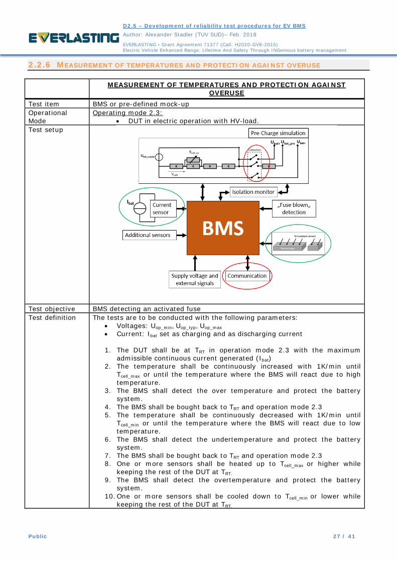
2.2.6 MEASUREMENT OF TEMPERATURES AND PROTECTION AGAINST OVERUSE
MEASUREMENT OF TEMPERATURES AND PROTECTION AGAINST OVERUSE
Test item BMS or pre-defined mock-up Operational Mode
Operating mode 2.3: • DUT in electric operation with HV-load.
Test setup
Test objective BMS detecting an activated fuse Test definition The tests are to be conducted with the following parameters:
• Voltages: Uop_min, Uop_typ, Uop_max • Current: Ibat set as charging and as discharging current
1. The DUT shall be at TRT in operation mode 2.3 with the maximum
admissible continuous current generated (Ibat) 2. The temperature shall be continuously increased with 1K/min until
Tcell_max or until the temperature where the BMS will react due to high temperature.
3. The BMS shall detect the over temperature and protect the battery system.
4. The BMS shall be bought back to TRT and operation mode 2.3 5. The temperature shall be continuously decreased with 1K/min until
Tcell_min or until the temperature where the BMS will react due to low temperature.
6. The BMS shall detect the undertemperature and protect the battery system.
7. The BMS shall be bought back to TRT and operation mode 2.3 8. One or more sensors shall be heated up to Tcell_max or higher while
keeping the rest of the DUT at TRT. 9. The BMS shall detect the overtemperature and protect the battery
system. 10. One or more sensors shall be cooled down to Tcell_min or lower while
keeping the rest of the DUT at TRT.

D2.5 – Development of reliability test procedures for EV BMS
Author: Alexander Stadler (TUV SUD)– Feb. 2018
EVERLASTING - Grant Agreement 71377 (Call: H2020-GV8-2015) Electric Vehicle Enhanced Range, Lifetime And Safety Through INGenious battery management
Public 28 / 41
11. The BMS shall detect the undertemperature and protect the battery system.
12. The test shall be repeated for all possible combinations of parameters
Monitored signals
• The status of all applicable contactors shall be recorded • The temperatures on the BMS sensors shall be recorded • External communication of the BMS shall be recorded (error codes)
Test criteria The DUT shall detect the over- or undertemperature of the system or singe cells and shall take appropriate measures, as defined by the manufacturer. Required minimum Functional Status: <=1.3 The manufacturer shall define the expected DUT response, including the expected functional status and expected communication and error messages.
2.2.7 DETECTION OF INSULATION FAULTS
DETECTION OF INSULATION FAULTS Test item BMS or pre-defined mock-up Operational Mode
Operating mode 2.2: • DUT in electric operation and without HV-load.
Operating mode 2.3: • DUT in electric operation and with HV-load.
Test setup
Test objective BMS detecting an insulation fault Test definition The tests shall be conducted with the following parameters:
• Voltages: Uop_min, Uop_typ, Uop_max • Operating mode: 2.2, 2.3 • insulation fault between UBat+ <-> GND and UBat- <-> GND
1. The DUT shall be in the defined operating mode at TRT 2. The insulation monitor shall be manipulated with a resistance to
simulate an insulation fault. 3. The BMS shall detect the insulation fault

D2.5 – Development of reliability test procedures for EV BMS
Author: Alexander Stadler (TUV SUD)– Feb. 2018
EVERLASTING - Grant Agreement 71377 (Call: H2020-GV8-2015) Electric Vehicle Enhanced Range, Lifetime And Safety Through INGenious battery management
Public 29 / 41
4. The test shall be repeated for all possible combinations of parameters
Monitored signals
• The status of all applicable contactors shall be recorded • The resistance of the inserted insulation fault shall be measured • External communication of the BMS shall be recorded (error codes)
Test criteria The DUT shall detect the insulation fault and shall take appropriate measures as defined by the manufacturer. Required minimum Functional Status: <=1.3 The manufacturer shall define the expected DUT response, including the expected functional status and expected communication and error messages.
2.2.8 TEST OF PRE-CHARGE INTERLOCK FUNCTIONS
TEST OF PRE-CHARGE INTERLOCK FUNCTIONS Test item BMS or pre-defined mock-up Operational Mode
Operating mode 2.2: • DUT in electric operation and without HV-load.
Test setup
Test objective BMS detecting an abnormal pre-charge behavior Test definition The tests shall be conducted with the following parameters:
• Voltages: Uop_min, Uop_typ, Uop_max 1. The DUT shall be in the defined operating mode at TRT 2. The pre-charge simulation shall be altered to simulate a too fast and a
too slow pre-charge behavior. 3. The signal “close contactors” is sent to the BMS 4. The BMS shall detect the deviation. 5. The test shall be repeated for all possible combinations of parameters
Monitored signals
• The status of all applicable contactors shall be recorded • The voltage Ubat_pre shall be recorded • External communication of the BMS shall be recorded (error codes)
D2.5 – Development of reliability test procedures for EV BMS
Author: Alexander Stadler (TUV SUD)– Feb. 2018
EVERLASTING - Grant Agreement 71377 (Call: H2020-GV8-2015) Electric Vehicle Enhanced Range, Lifetime And Safety Through INGenious battery management
Public 30 / 41
Test criteria The DUT shall detect abnormal pre-charge behavior and must not close the main contactors. Required minimum Functional Status: <=1.3 The manufacturer shall define the expected DUT response, including the expected functional status and expected communication and error messages.
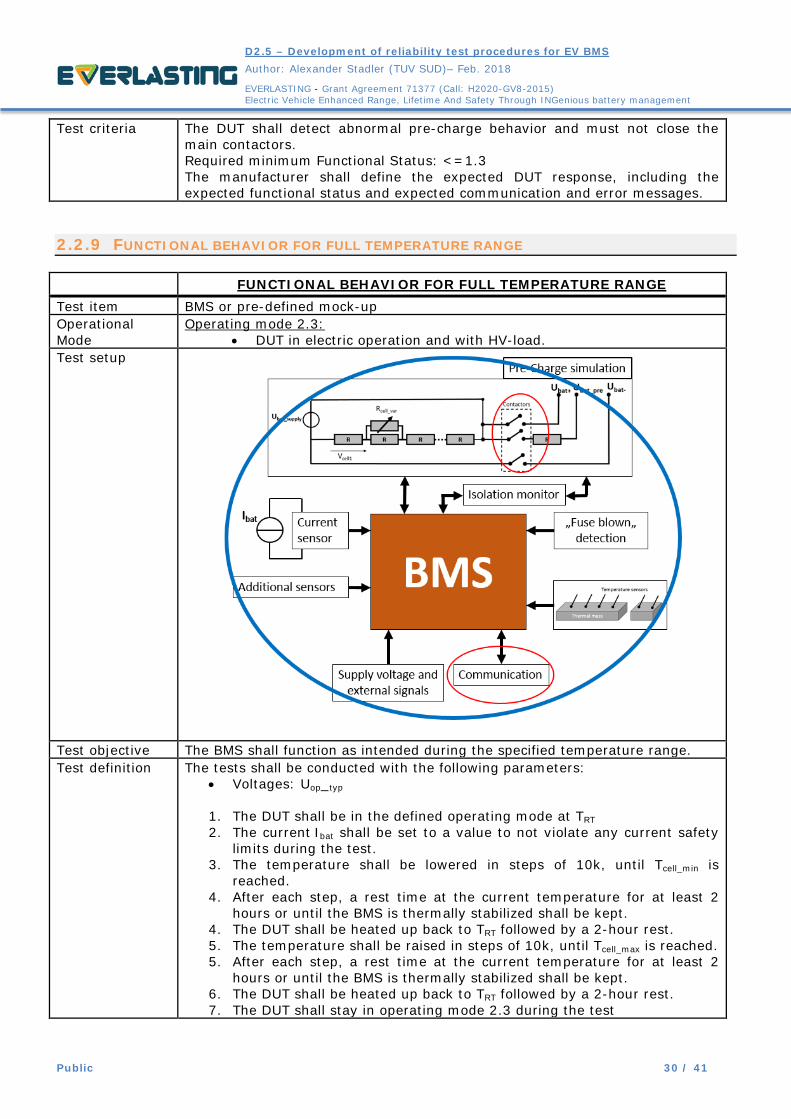
2.2.9 FUNCTIONAL BEHAVIOR FOR FULL TEMPERATURE RANGE
FUNCTIONAL BEHAVIOR FOR FULL TEMPERATURE RANGE Test item BMS or pre-defined mock-up Operational Mode
Operating mode 2.3: • DUT in electric operation and with HV-load.
Test setup
Test objective The BMS shall function as intended during the specified temperature range. Test definition The tests shall be conducted with the following parameters:
• Voltages: Uop_typ
1. The DUT shall be in the defined operating mode at TRT 2. The current Ibat shall be set to a value to not violate any current safety
limits during the test. 3. The temperature shall be lowered in steps of 10k, until Tcell_min is
reached. 4. After each step, a rest time at the current temperature for at least 2
hours or until the BMS is thermally stabilized shall be kept. 4. The DUT shall be heated up back to TRT followed by a 2-hour rest. 5. The temperature shall be raised in steps of 10k, until Tcell_max is reached. 5. After each step, a rest time at the current temperature for at least 2
hours or until the BMS is thermally stabilized shall be kept. 6. The DUT shall be heated up back to TRT followed by a 2-hour rest. 7. The DUT shall stay in operating mode 2.3 during the test

D2.5 – Development of reliability test procedures for EV BMS
Author: Alexander Stadler (TUV SUD)– Feb. 2018
EVERLASTING - Grant Agreement 71377 (Call: H2020-GV8-2015) Electric Vehicle Enhanced Range, Lifetime And Safety Through INGenious battery management
Public 31 / 41
Monitored signals
• The status of all applicable contactors shall be recorded • The environmental temperature shall be recorded • External communication of the BMS shall be recorded (error codes)
Test criteria The DUT shall function throughout the test as intended. Required minimum Functional Status: 1.1 The manufacturer shall define the expected DUT response, including the expected functional status and expected communication and error messages.
2.3 ELECTRICAL TESTS
When installed in an automotive vehicle, the BMS will be exposed to certain external disturbances caused by the vehicle’s low voltage network. The various possible stress scenarios have been defined by the standard ISO 16750-2 (“Road vehicles — Environmental conditions and testing for electrical and electronic equipment – Part 2: Electrical loads”) and shall be applied to the BMS to be tested. In order to simulate the required function, the setup as shown in Figure 2 shall be used to operate the BMS.
The following tests shall be performed:
1. Direct current supply voltage a. Operation of the DUT at minimum and maximum supply voltage
2. Overvoltage a. Operation of the DUT with increased supply voltage
3. Superimposed alternating voltage a. Operation of the DUT with a residual AC current on the voltage supply line
4. Slow decrease and increase of supply voltage 5. Discontinuities in supply voltage
a. Short voltage drops in the supply voltage b. Voltage variations during and after cranking c. Voltage spike during a load dump, e.g. due to disconnection of the 12V battery
6. Reversed voltage a. Simulating a falsely connected battery
7. Ground reference and supply offset a. Simulate a ground offset for different ground/supply lines of the DUT
8. Open circuit tests a. Simulate single and multiple line interruptions of external signal and communication
lines 9. Short circuit protection
a. Simulate short circuits on signal lines 10. Withstand voltage
a. Verify dielectric withstand voltage capability of the DUT of circuits with galvanic insulation
11. Insulation resistance a. Ensure a minimum ohmic resistance between galvanic isolated circuits of the DUT.

D2.5 – Development of reliability test procedures for EV BMS
Author: Alexander Stadler (TUV SUD)– Feb. 2018
EVERLASTING - Grant Agreement 71377 (Call: H2020-GV8-2015) Electric Vehicle Enhanced Range, Lifetime And Safety Through INGenious battery management
Public 32 / 41
2.4 EVALUATION OF SOC & SOH PERFORMANCE
The reliability of the BMS in terms of SoC or SoH calculation can be evaluated using real battery cells. As outlined in section 1.2 Definition of Test Sample the BMS can either be tested in full scale, with all inputs and outputs in operation, or as a reduced mock-up. When testing in full scale, a complete prototype battery will be necessary to evaluate SoC and SoH performance of the BMS. When testing a reduced mock-up, a smaller number of cells can be used, preferably staying below the previously discussed 60V. A possible Test setup with a few single cells is shown in the following (Figure 5).
Figure 5: Possible test setup for SoC validation
When assembling multiple cells in series, a battery cycler capable of cycling modules or small batteries will be necessary. Those cyclers are usually capable of providing several kW of power and therefore have a high current range (e.g. 0-300A). When using cells with small capacities in series, the total capacity of the setup will still be small, and a possible cut-off current, typical C/10 or C/20, will be even smaller. Therefore, it is advised to choose cells with an adequate minimal capacity to stay within a reasonable current range of the cycler used.

D2.5 – Development of reliability test procedures for EV BMS
Author: Alexander Stadler (TUV SUD)– Feb. 2018
EVERLASTING - Grant Agreement 71377 (Call: H2020-GV8-2015) Electric Vehicle Enhanced Range, Lifetime And Safety Through INGenious battery management
Public 33 / 41
2.4.1 DETERMINING SOC ESTIMATION PERFORMANCE
Testing the SoC performance of a BMS is very extensive as many factors can influence the SoC calculation. Also, the evaluation of the predicted SoC is not trivial. A general approach with a test setup with one single cell has been published by C. Campestrini et al: Validation and benchmark methods for battery management system functionalities: State of charge estimation algorithms. A detailed of SoC an its evaluation can be found in the EVERLASTING whitepaper D8.6 – White Paper 03: “EVALUATION OF SOC ACCURACY” C. Campestrini et al proposed three different synthetic load cycles to represent the different aspects of a battery behavior [3]:
• Low-dynamic profile • High-dynamic profile • Long-term profile
The power profiles have been made publicly available [4] and are meant to be divided by the nominal voltage of the cell and then scaled up to the maximum admissible current of the cell [3]. As a full pack or at least a mock-up of a few cells will be used, the power profile will need to be scaled up accordingly. The manufacturer can provide his own power profiles for different loads, if he is able to demonstrate that those profiles represent the intended use scenario of the BMS. If no specific profiles are available, the above referenced synthetic load cycles can be used. In the shown study [3], the performance of the BMS is continuously analyzed and compared to the values obtained through the cell external cell cycler. At the end of each performance test the residual charge is measured and compared to the estimated values of the BMS. As the performance of the SoC algorithm is only one aspect of many to be tested, the efforts to qualify its performance will be reduced to get a basic test result. Therefore, the proposed power profiles will be performed in different temperature and SoC regimes, while measuring the residual charge at different steps of the cycling. The difference in the SoC calculated by the BMS and the SoC measured by the test bench can be used to judge the quality of the BMS’S algorithm. If the SoC algorithm needs to be validated in more detail, the in this test generated data can be used in a separate study to optimize the BMS. In order to perform those tests, the in Figure 5 shown test setup will be used A full cycle shall be one charge -discharge cycle with CC-CV charge and CC discharge. The values shall be chosen as specified by the cell manufacturer. The discharge of the remaining residual capacity shall be done using the same values. The minimum and maximum temperature values shall be chosen in a way, that the cell still allows charging and discharging with a reasonable current. The load profile is to be scaled for the maximum allowed currents for each temperature step. The measured residual capacities shall be compared to the ones calculated by the BMS for each of the different tests. The manufacturer of the BMS shall give an expected accuracy of the BMS algorithm to compare the archived results to.

D2.5 – Development of reliability test procedures for EV BMS
Author: Alexander Stadler (TUV SUD)– Feb. 2018
EVERLASTING - Grant Agreement 71377 (Call: H2020-GV8-2015) Electric Vehicle Enhanced Range, Lifetime And Safety Through INGenious battery management
Public 34 / 41
2.4.1.1 SoC test 1: Slow dynamic load
The SoC test to evaluate the BMS performance for low dynamic loads shall be done as shown in Figure 6.
Figure 6: SoC validation with low dynamic profile
The Test shall be done at the following temperatures: • Tcell_min Minimum operating temperature of the cell to be used with the BMS • TRT Room temperature, 23°C • Tcell_max Maximum operating temperature of the cell to be used with the BMS
2.4.1.2 SoC test 2: Highly dynamic load
Figure 7: SoC validation with high dynamic profile
The test with the high dynamic load profile shall be done in three different steps as illustrated in Figure 7, shortening the duration of the profile in order to evaluate a narrower SoC windows.

D2.5 – Development of reliability test procedures for EV BMS
Author: Alexander Stadler (TUV SUD)– Feb. 2018
EVERLASTING - Grant Agreement 71377 (Call: H2020-GV8-2015) Electric Vehicle Enhanced Range, Lifetime And Safety Through INGenious battery management
Public 35 / 41
The Test shall be done at the following temperatures: • Tcell_min Minimum operating temperature of the cell to be used with the BMS • TRT Room temperature, 23°C • Tcell_max Maximum operating temperature of the cell to be used with the BMS
2.4.1.3 SoC test 3: Long term profile
In the work of C. Campestrini et al it is proposed to apply the long-term profile for in total seven days, while varying the temperature within a 24h window [3]. This approach is feasible when calculating the SoC performance continuously during the cycling. As is this test approach only the residual capacity will be measured against the estimated SoC of the BMS, the long-term profile will be split in different parts. First, 24 hour cycling steps at the different test temperatures shall be done to measure effects of different temperatures and to identify the sensitivity of the BMS algorithm to different temperatures (Figure 8, Figure 9, and Figure 10). Then a cycling of six days at all temperature levels shall be performed (Figure 11).
Figure 8: SoC validation with 24h long time profile at Tcell_min
Figure 9: SoC validation with 24h long time profile at TRT
Figure 10: SoC validation with 24h long time profile at Tcell_max
The temperature shall be ramped up/down with a gradient of 1k/min. The temperature shall be ramped down that one hour before end of the load profile the DUT can stabilize at TRT to deliver a comparable value for the residual capacity.

D2.5 – Development of reliability test procedures for EV BMS
Author: Alexander Stadler (TUV SUD)– Feb. 2018
EVERLASTING - Grant Agreement 71377 (Call: H2020-GV8-2015) Electric Vehicle Enhanced Range, Lifetime And Safety Through INGenious battery management
Public 36 / 41
Figure 11: SoC validation with six days long time profile at different temperatures
For the six days of cycling at different temperatures the ramp down of temperature before the end of the tests shall be analogue to the cycling shown before. The measured values for the residual capacity shall be compared to the estimated SoC values of the BMS. The manufacturer shall state which accuracy his prediction should meet.
2.4.2 DETERMINING SOH ESTIMATION PERFORMANCE
The SoH determination of the BMS gives an estimation of the state of health, indicating the current degradation state of the battery in comparison to a new battery. The SoH does not describe a physical value that can be verified by a direct measurement, in comparison to the SoC prediction for example. There are no fixed parameters for the determination of a SoH. Every BMS manufacturer defines his own criteria based on the requirements and the intended use. Also, the algorithm on how the SoH is calculated is usually not made available by the BMS manufacturer. Therefore, a measurement of the performance of a SoH calculation can only be done with the help of the BMS manufacturer. In the automotive industry, there are two commonly known and used criteria for SoH evaluation: the capacity of a battery system and its impedance. To define the end of life (EOL) of a battery system the following limits are commonly used [5].
• CEOL=0.8*CBOL Where a CBOL is the battery capacity at begin of live (BOL), and CEOL is the minimum accepted capacity before the battery is defined as not usable for automotive purposes anymore.
• REOL=2*RBOL With RBOL as initial impedance and REOL as the maximum accepted impedance of the battery. A BMS SoH calculation may take those values into account but can also be based on further information as for example accumulated energy throughput or number of cycles, see Figure 12. All the values recorded by the BMS will then be weighted and merged by an algorithm to determine a SoH expressed in the range of 100%-0%; where as 100% will represent a new battery, and 0% will indicate that the battery is at end of life.

D2.5 – Development of reliability test procedures for EV BMS
Author: Alexander Stadler (TUV SUD)– Feb. 2018
EVERLASTING - Grant Agreement 71377 (Call: H2020-GV8-2015) Electric Vehicle Enhanced Range, Lifetime And Safety Through INGenious battery management
Public 37 / 41
Figure 12: Possible input information for SoH prediction
In order to evaluate the SoH calculation, the input parameters of the BMS must be validated if possible. Therefore, the manufacturer of the BMS must disclose the input variables used to calculate the SoH and in which way they are stored in the BMS. A validation of the measurable parameters can then be done by comparing the values recorded and calculated by the BMS with values verified by an external test setup. In the proposed test case, it is assumed that the values battery capacity and battery impedance will be validated. The evaluation of the remaining capacity can be done by using an external cycler and performing a full cycle on the tested battery system. Battery impedance can be measured by charging and discharging the battery with high current pulses at different SoC levels. Both values are temperature dependent. Together with the BMS manufacturer it must be decided if the remaining capacity is to be measured at different temperatures. It must also be defined at which SoC levels and at which temperatures the impedance of the battery system should be measured. The objective is to measure values that can be compared to the values acquired by the BMS through normal operation. The measurement of those values should be done from time to time while performing a long time cycling of the battery to simulate its degradation in between measurements. The described measurements do not represent a standard use case, therefore the BMS will be deactivated during those to avoid generating data that will influence the BMS performance.

D2.5 – Development of reliability test procedures for EV BMS
Author: Alexander Stadler (TUV SUD)– Feb. 2018
EVERLASTING - Grant Agreement 71377 (Call: H2020-GV8-2015) Electric Vehicle Enhanced Range, Lifetime And Safety Through INGenious battery management
Public 38 / 41
The in chapter 0 shown test setup will be extended as shown in Figure 13 to be able to perform the tests:
Figure 13: Possible test setup for validation of single parameters for SoH
In parallel to the BMS operating the battery and connecting an electrical cycler to the battery main terminals, the simulated battery will be connected directly to an external cycler, allowing the operation of the battery without the BMS in function. For this type of test setup, a smaller battery model consisting of a few cells is required. Performing this test on battery level will be very costly to do, as for the safe cycling of a whole battery pack with disabled the BMS the whole pack will need to be modified, and the external cycler will require its own BMS system. The overall test procedure will look as shown in Figure 14.
Figure 14: Possible test procedure for validation of SoH parameters
D2.5 – Development of reliability test procedures for EV BMS
Author: Alexander Stadler (TUV SUD)– Feb. 2018
EVERLASTING - Grant Agreement 71377 (Call: H2020-GV8-2015) Electric Vehicle Enhanced Range, Lifetime And Safety Through INGenious battery management
Public 39 / 41
• The battery system will first be characterized performing a full cycle to measure its capacity, respecting the same cell voltage limits as used by the BMS
• A series of impedance pulses will be done at different SoC levels • After a rest the battery will be charged to 100% SoC using a CC-CV charge • During a rest at 100% SoC the BMS will be activated • The battery will be discharged down to 30% SoC using a driving profile
o A realistic driving profile for the intended use of the BMS shall be provided by the manufacturer. If no profile is available, the high-dynamic profile shown in chapter 0 can be used.
o The limit of 30% can be adjusted depending on the expected usage scenario of the battery
• After the end of the cycle, the battery will be fully charged using a CC-CV charge • The cycle with BMS operation shall be repeated for seven days, then the BMS will be
switched off while the battery is at 100% SoC. The values for capacity and impedance estimated by the BMS shall be logged after the cycling.
• The whole test procedure with and without BMs operation shall be repeated until the battery shows noticeable ageing effects. A degradation of at least 10% SoH is recommended. If the cells age quite fast, a longer test time will help to generate more reliable data.
The cycling with BMS in operation shall be done at different temperatures to be defined by the manufacturer. The previously defined temperatures can be used as a guide line but can be adjusted to allow a higher energy throughput during cycling.
• Tcell_min Minimum operating temperature of the cell to be used with the BMS • TRT Room temperature, 23°C • Tcell_max Maximum operating temperature of the cell to be used with the BMS
The during cycling measured values shall be compared to the estimated values of the BMS. The manufacturer shall state which accuracy his prediction of the relevant values should meet.

D2.5 – Development of reliability test procedures for EV BMS
Author: Alexander Stadler (TUV SUD)– Feb. 2018
EVERLASTING - Grant Agreement 71377 (Call: H2020-GV8-2015) Electric Vehicle Enhanced Range, Lifetime And Safety Through INGenious battery management
Public 40 / 41
CONCLUSIONS
In this document, various test cases have been defined based on existing test standards for lithium ion batteries. A testing environment to test a BMS without battery cells has been proposed, and the possibility to test on a reduced mock-up of a battery system has been discussed. The proposed test cases have been adapted to be compatible with the requirement of testing a BMS without a battery system. In order to assess the generated test results, the performance and safety requirements defined by the manufacturer of the BMS will be used as a reference. For validation and refinement, the proposed tests will be conducted on a prototype BMS system for the EVERLASTING project. Once the first test series is completed, the results can be compared to the results usually archived when testing a full-scale battery.

D2.5 – Development of reliability test procedures for EV BMS
Author: Alexander Stadler (TUV SUD)– Feb. 2018
EVERLASTING - Grant Agreement 71377 (Call: H2020-GV8-2015) Electric Vehicle Enhanced Range, Lifetime And Safety Through INGenious battery management
Public 41 / 41
REFERENCES
[1] J. Alvarez et al., D6.1–Analysis of the state of the art on BMS. EVERLASTING / LION SMART, 02/2017 [2] B. Scrosati, J. Garche, and W. Tillmetz, Eds., Advances in battery technologies for electric vehicles. Amsterdam: WP, Woodhead Publishing/Elsevier, 2015. [3] Campestrini et al, Validation and benchmark methods for battery management system functionalities: State of charge estimation algorithms, J. Energy Storage 7 (2016), 38-51 [4] http://www.ees.ei.tum.de/en/media/downloads/validation/ , 12.02.2018 [5] W. Waag, C. Fleischer, D. Sauer, Critical review of the methods for monitoring of lithium-ion batteries in electric and hybrid vehicles, J. Power Sources 258 (2014), 321-339