D1LVS-T GPS CONTROLLER - TWR Lighting · D1LVS-T GPS CONTROLLER ADDENDUM NOTE PLEASE READ ......
34
4300 WINDFERN RD. #100 HOUSTON TX 77041-8943 VOICE (713) 973-6905 FAX (713) 973-9352 WEB: twrlighting.com D1LVS-T GPS CONTROLLER ADDENDUM NOTE PLEASE READ ***IMPORTANT NOTICE*** This controller has been modified from a D1LVS to a D1LVS-T GPS. The changes are as follows: One (1)40 uF capacitor has been removed from this controller and PCB#1 has been changed from a STH01283 to a STH01285HK GPS. Please adhere to these changes when servicing this unit. FOR ADDITIONAL INFORMATION OR HELP, PLEASE CONTACT OUR TECHNICAL SUPPORT GROUP AT (713) 973-6905 EXT 132, 136, OR 151.
Transcript of D1LVS-T GPS CONTROLLER - TWR Lighting · D1LVS-T GPS CONTROLLER ADDENDUM NOTE PLEASE READ ......

4300 WINDFERN RD. #100 HOUSTON TX 77041-8943
VOICE (713) 973-6905 FAX (713) 973-9352 WEB: twrlighting.com
D1LVS-T GPS CONTROLLER
ADDENDUM
NOTE
PLEASE READ
***IMPORTANT NOTICE***
This controller has been modified from a D1LVS to a D1LVS-T GPS. The changes are as follows: One (1)40 uF capacitor has been removed from this controller and PCB#1 has been changed from a STH01283 to a STH01285HK GPS.
Please adhere to these changes when servicing this unit. FOR ADDITIONAL INFORMATION OR HELP, PLEASE CONTACT OUR TECHNICAL SUPPORT GROUP AT (713) 973-6905 EXT 132, 136, OR 151.

C:\Documents and Settings\esalazar\Local Settings\Temporary Internet Files\OLK1\D-1LVS Rev 040903.doc 12/98; Rev. 6/99; Rev. 03/00; Rev. 05/00; Rev. 07/07/00 (dwg H01-226B); Reg. 07/08/00 (Pg. 9, DSI); Rev. 07/00 (o2L/H); Rev. 10/18/00 (retyped & o2-dwgs.) Rev. 05/14/01 (revised pg 1 – mounting width; warranty & return policy) Rev. 03/20/03 (TWR logo Dwgs) Rev 04/09/03
4300 WINDFERN RD. #100 HOUSTON TX 77041-8943
VOICE (713) 973-6905 FAX (713) 973-9352 WEB: www.twrlighting.com
IMPORTANT!!!
PLEASE TAKE THE TIME TO FILL OUT THE FORM COMPLETELY. FILE IN A SAFE PLACE. IN THE EVENT YOU EXPERIENCE PROBLEMS WITH OR HAVE QUESTIONS CONCERNING YOUR CONTROLLER, THE FOLLOWING INFORMATION IS NECESSARY TO OBTAIN PROPER SERVICE AND PARTS.
MODEL # D-1LVS SERIAL # PURCHASE DATE PURCHASED FROM

D-1LVS CONTROLLER
C:\Documents and Settings\esalazar\Local Settings\Temporary Internet Files\OLK1\D-1LVS Rev 040903.doc 12/98; Rev. 6/99; Rev. 03/00; Rev. 05/00; Rev. 07/07/00 (dwg H01-226B); Reg. 07/08/00 (Pg. 9, DSI); Rev. 07/00 (o2L/H); Rev. 10/18/00 (retyped & o2-dwgs.) Rev. 05/14/01 (revised pg 1 – mounting width; warranty & return policy) Rev 03/20/03 (TWR logo Dwgs) Rev 04/09/03
TABLE OF CONTENTS 1.0 INTRODUCTION...............................................................................................................1 1.1 APPLICATION....................................................................................................... 1 1.2 SPECIFICATIONS OF EQUIPMENT .................................................................... 1 2.0 INSTALLATION................................................................................................................. 2 2.1 POWER SUPPLY CONTROL CABINET MOUNTING .......................................... 2 2.2 PHOTOCELL HOUSING....................................................................................... 2 2.3 PHOTOCELL WIRING .......................................................................................... 2 2.4 POWER WIRING................................................................................................... 3 2.5 TOWER LIGHTING KIT......................................................................................... 3 2.5.1 Beacon Mounting....................................................................................... 3 2.5.2 Lighting Kit Wiring...................................................................................... 4 2.6 ALARM WIRING................................................................................................................ 4 2.6.1 Alarm testing ......................................................................................................... 4 2.6.2 Strobe Failure (SF)................................................................................................ 4 2.6.3 Power Failure (PF) ................................................................................................ 4 2.6.4 Photocell (PC) ....................................................................................................... 5 2.7 CONTROLLER CONFIGURATION................................................................................... 5 3.0 THEORY OF OPERATION ............................................................................................... 6 3.1 THE POWER SUPPLY.......................................................................................... 6 3.2 THE FLASHTUBE ................................................................................................. 6 3.3 TIMING CIRCUIT .................................................................................................. 7 3.4 TRIGGER CIRCUIT............................................................................................... 7 3.5 ALARM CIRCUITS ................................................................................................ 7 3.5.1 Strobe Failure (SF) .................................................................................... 7 3.5.2 Photocell (PC)............................................................................................ 7 3.6 BLEEDER CIRCUIT .............................................................................................. 8 3.7 STROBE DIAGNOSTIC CIRCUITS ...................................................................... 8 3.7.1 Control Power On ...................................................................................... 8 3.7.2 High Voltage .............................................................................................. 8 3.7.3 Trigger Voltage .......................................................................................... 9 3.7.4 Nightmode ................................................................................................. 9 3.7.5 Primary Timing........................................................................................... 9 3.7.6 Timing Signal Verify................................................................................... 9 3.7.7 Flash Verified............................................................................................. 9 3.7.8 Strobe Fail Test ......................................................................................... 9

D-1LVS CONTROLLER
C:\Documents and Settings\esalazar\Local Settings\Temporary Internet Files\OLK1\D-1LVS Rev 040903.doc 12/98; Rev. 6/99; Rev. 03/00; Rev. 05/00; Rev. 07/07/00 (dwg H01-226B); Reg. 07/08/00 (Pg. 9, DSI); Rev. 07/00 (o2L/H); Rev. 10/18/00 (retyped & o2-dwgs.) Rev. 05/14/01 (revised pg 1 – mounting width; warranty & return policy) Rev 03/20/03 (TWR logo Dwgs) Rev 04/09/03
4.0 TROUBLE SHOOTING ................................................................................................... 10 4.1 TOOL REQUIREMENTS..................................................................................... 10 4.2 DIAGNOSTIC EVALUATION .............................................................................. 10 4.3 TROUBLE SHOOTING ASSISTANCE................................................................ 11 4.3.1 Flash Verify LED - Out............................................................................. 11 4.3.2 Control Power On LED - Out ................................................................... 11 4.3.3 Primary Timing LED Out.......................................................................... 11 4.3.4 False or Nonexistent Beacon Alarms ...................................................... 12 5.0 MAINTENANCE GUIDE.................................................................................................. 13 5.1 FLASHTUBE REPLACEMENT ........................................................................... 13 5.2 POWER SUPPLY................................................................................................ 13 5.3 PHOTOCELL....................................................................................................... 13 6.0 MAJOR COMPONENTS PARTS LIST ........................................................................... 14 7.0 RECOMMENDED SPARE PARTS LIST......................................................................... 16 PRODUCT WARRANTY............................................................................................................. 17 RETURN POLICY .................................................................................................................18 RETURN MERCHANDISE AUTHORIZATION FORM (RMA) .................................................... 19

D-1LVS CONTROLLER
C:\Documents and Settings\esalazar\Local Settings\Temporary Internet Files\OLK1\D-1LVS Rev 040903.doc 12/98; Rev. 6/99; Rev. 03/00; Rev. 05/00; Rev. 07/07/00 (dwg H01-226B); Reg. 07/08/00 (Pg. 9, DSI); Rev. 07/00 (o2L/H); Rev. 10/18/00 (retyped & o2-dwgs.) Rev. 05/14/01 (revised pg 1 – mounting width; warranty & return policy) Rev 03/20/03 (TWR logo Dwgs) Rev 04/09/03
APPENDIX Chassis Layout.....................................................................................................H40-283 Wiring Diagram ................................................................................................... M01-283
Housing Details D-1LVS......................................................................................HD0-283
Installation Guideline ............................................................................................ INS-283
Photocell Housing Detail ....................................................................................... 100239
Tower Lighting Kit - Cable ...................................................................................... 500-12
Control PCB #1 ................................................................................................. H01-226B
High Voltage Rectifier PCB #2 ......................................................................... H02-226A
Relay PCB #3.......................................................................................................H03-226
Strobe Beacon Detail ........................................................................................... 100437i
D-1LVS CONTROLLER
C:\Documents and Settings\esalazar\Local Settings\Temporary Internet Files\OLK1\D-1LVS Rev 040903.doc 3/8/2006 12/98; Rev. 6/99; Rev. 03/00; Rev. 05/00; Rev. 07/07/00 (dwg H01-226B); Reg. 07/08/00 (Pg. 9, DSI); Rev. 07/00 (o2L/H); Rev. 10/18/00 (retyped & o2-dwgs.) Rev. 05/14/01 (revised pg 1 – mounting width; warranty & return policy) Rev 03/20/03 (TWR logo – Dwgs) Rev 04/09/03 - 1 -
1.0 INTRODUCTION
TWR Lighting Division’s Model D-1LVS Type L-865 Controller has been designed and built to the Federal Aviation Administration’s (FAA) Advisory Circular 150/5345-43E with safety and reliability in mind. TWR is committed to providing our customers with some of the best products and services available. TWR welcomes you to our family of fine products and we look forward to servicing your needs now and in the future.
1.1 APPLICATION
The D-1LVS L-865 Controller is for use on lighting structures or towers that are approved to be lighted with Medium Intensity Strobes in accordance with the FAA’s Advisory Circular 70/7460-1K. Structures from 201' to 350' may be lighted with Medium Intensity lights. NOTE: Structures exceeding 500' will require to be painted in addition to this lighting for added visual hazard marking.
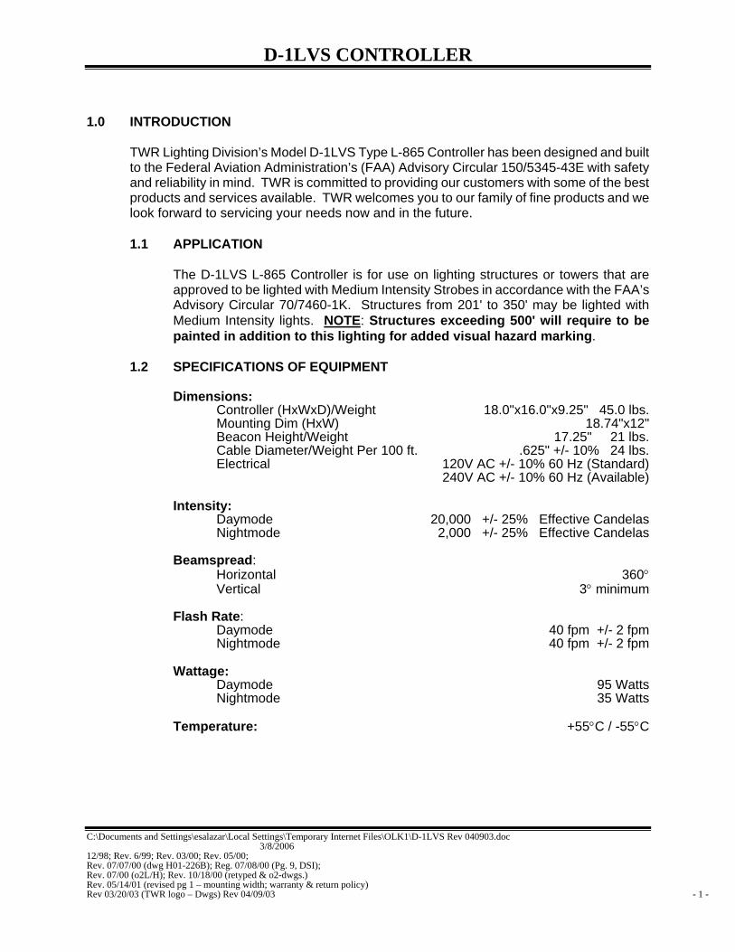
1.2 SPECIFICATIONS OF EQUIPMENT
Dimensions: Controller (HxWxD)/Weight 18.0"x16.0"x9.25" 45.0 lbs. Mounting Dim (HxW) 18.74"x12" Beacon Height/Weight 17.25" 21 lbs. Cable Diameter/Weight Per 100 ft. .625" +/- 10% 24 lbs. Electrical 120V AC +/- 10% 60 Hz (Standard)
240V AC +/- 10% 60 Hz (Available)
Intensity: Daymode 20,000 +/- 25% Effective Candelas Nightmode 2,000 +/- 25% Effective Candelas
Beamspread:
Horizontal 360° Vertical 3° minimum
Flash Rate:
Daymode 40 fpm +/- 2 fpm Nightmode 40 fpm +/- 2 fpm
Wattage:
Daymode 95 Watts Nightmode 35 Watts
Temperature: +55°C / -55°C

D-1LVS CONTROLLER
C:\Documents and Settings\esalazar\Local Settings\Temporary Internet Files\OLK1\D-1LVS Rev 040903.doc 3/8/2006 12/98; Rev. 6/99; Rev. 03/00; Rev. 05/00; Rev. 07/07/00 (dwg H01-226B); Reg. 07/08/00 (Pg. 9, DSI); Rev. 07/00 (o2L/H); Rev. 10/18/00 (retyped & o2-dwgs.) Rev. 05/14/01 (revised pg 1 – mounting width; warranty & return policy) Rev 03/20/03 (TWR logo – Dwgs) Rev 04/09/03 - 2 -
2.0 INSTALLATION
2.1 POWER SUPPLY CONTROL CABINET MOUNTING
The power supply control cabinet can be located at the base of the structure or in an equipment building. Mounting Dimensions can be found in Section 1.2 on page 1. Pay particular attention when choosing your controller mounting location to ensure proper door opening and room for service personnel. Refer to installation drawing HDO-283 for ease of install.
2.2 PHOTOCELL HOUSING
The standard photocell housing is supplied with a 20' pigtail of 16 AWG Type TFFN wire. On occasion, in mounting of the photocell, an additional amount of wire may be required. Refer to drawing 100239 for proper assistance on determining gauge of wire for your specific needs.
2.3 PHOTOCELL WIRING
(Refer to Drawings HD0-283 and H40-283)
If the control cabinet is mounted inside an equipment building, the photocell should be mounted vertically on ½” conduit outside the building above the eaves facing north. Wiring from the photocell housing socket to the control cabinet should consist of one each; red, black, and white wires. The white wire is connected to the socket terminal marked “COM”, the black wire is connected to the socket terminal marked “B”, and the red wire is connected to the socket terminal marked “R”. These socket connections are made by using .25" quick connect terminals, which must be crimped to the wires. The photocell should be positioned so that it does not “see” ambient light, which would prevent it from switching to the nightmode.
If the control cabinet is mounted outside an equipment building, the photocell should be mounted vertically on ½” conduit so the photocell is above the control cabinet. Care must be taken to assure that the photocell does not “see” any ambient light that would prevent it from switching into the nightmode. The photocell housing socket wiring is the same as above. 2.3.1 Connect the BLACK wire from the photocell to TB1-8.
2.3.2 Connect the RED wire from the photocell to TB1-6.
2.3.3 Connect the WHITE wire from the photocell to TB1-7.

D-1LVS CONTROLLER
C:\Documents and Settings\esalazar\Local Settings\Temporary Internet Files\OLK1\D-1LVS Rev 040903.doc 3/8/2006 12/98; Rev. 6/99; Rev. 03/00; Rev. 05/00; Rev. 07/07/00 (dwg H01-226B); Reg. 07/08/00 (Pg. 9, DSI); Rev. 07/00 (o2L/H); Rev. 10/18/00 (retyped & o2-dwgs.) Rev. 05/14/01 (revised pg 1 – mounting width; warranty & return policy) Rev 03/20/03 (TWR logo – Dwgs) Rev 04/09/03 - 3 -
2.3.4 Install the photocell into the receptacle and twist to the right while depressing
to lock into place.
Note: When installing multiple controllers together, the photocell is only required on one (1) unit. It can be installed on the master (or) slave. SSR interconnect wire must be common to all units. D2/3LV SSR TB3-2 / D-1LVS SSR TB1-6.
2.4 POWER WIRING
(Refer to Drawing H40-283)
Power wiring to the control cabinet should be in accordance with local methods and the National Electric Code (NEC).
2.4.1 A 15 amp circuit breaker is recommended at service panel.
2.4.2 Connect the “HOT” side of the 120V AC line to TB1-9.
2.4.3 Connect the “NEUTRAL” side of the 120V AC line to TB1-10.
2.4.4 Connect the AC ground to the ground stud to the lower right of the terminal
block TB1.
2.4.5 Controller panel should be connected to tower and/or building grounding system with the exception of installations on AM/RF Applications where controller grounding to earth ground is prohibited. Ground the controller only to the tower itself using a suitable RF ground.
2.5 TOWER LIGHTING KIT
When installing this system, the customer will need to use strobe cable to wire the strobe beacon. Refer to Lighting Kit Drawing 500-12 for cable installation.
2.5.1 Beacon Mounting
(Refer to Drawing HDO-283)
2.5.1.1 Bolt the beacon to the mounting plate using four 5/8" x 1 1/2" galvanized bolts that are supplied. Installer should make sure to check for full thread engagement on Anco locknut. Allow 18" clearance in back of the hinge (25" from the center of the base) to tilt lens back without hitting an obstruction.
2.5.1.2 Level the beacon using the level at the base of the lens. Shims
may be used under beacon base or triple nutting each bolt with palnuts on all four (4) nuts.

D-1LVS CONTROLLER
C:\Documents and Settings\esalazar\Local Settings\Temporary Internet Files\OLK1\D-1LVS Rev 040903.doc 3/8/2006 12/98; Rev. 6/99; Rev. 03/00; Rev. 05/00; Rev. 07/07/00 (dwg H01-226B); Reg. 07/08/00 (Pg. 9, DSI); Rev. 07/00 (o2L/H); Rev. 10/18/00 (retyped & o2-dwgs.) Rev. 05/14/01 (revised pg 1 – mounting width; warranty & return policy) Rev 03/20/03 (TWR logo – Dwgs) Rev 04/09/03 - 4 -

D-1LVS CONTROLLER
C:\Documents and Settings\esalazar\Local Settings\Temporary Internet Files\OLK1\D-1LVS Rev 040903.doc 3/8/2006 12/98; Rev. 6/99; Rev. 03/00; Rev. 05/00; Rev. 07/07/00 (dwg H01-226B); Reg. 07/08/00 (Pg. 9, DSI); Rev. 07/00 (o2L/H); Rev. 10/18/00 (retyped & o2-dwgs.) Rev. 05/14/01 (revised pg 1 – mounting width; warranty & return policy) Rev 03/20/03 (TWR logo – Dwgs) Rev 04/09/03 - 5 -
2.5.2 Lighting Kit Wiring
Install wiring between the controller to the beacon utilizing strobe cable method. (TWR LIGHTING CANNOT WARRANTY SYSTEMS THAT EMPLOY SPLICING CABLE.) Refer to drawings HDO-283 and 500-12 for install of lighting kits. Follow these minimum guidelines as well as any local or end user addition requirements. Installing lighting kits will require lifting of the cable by the supplied cable grip or conduit to affix to the tower. Always work safely and adhere to all OSHA Safety Guidelines when lifting wiring or working on the structure or tower itself. It is the installer’s responsibility to install the lighting kit in a safe manner. Installers can request from OSHA their requirements 29CFT 1926.21 and 29CFR 1926.105 to ensure compliance to regulations.
NOTE: On occasion a set of custom lighting kit drawings may be specifically requested by a customer and installed in this manual. In cases such as this, the drawings will precede the manual if a conflict occurs.
2.6 ALARM WIRING
Individual alarm contacts (Form C) are provided for strobe failure, power failure and photocell on. It is left up to the customer or installer on how they choose to utilize these contacts with their monitoring equipment. Alarm configurations are shown on drawing H40-283. 2.6.1 Alarm testing
To test alarms, follow these procedures using an “ohm” meter between alarm common and alarm points.
2.6.2 Strobe Failure (SF)
Strobe failure testing can be performed in either day or nightmode strobe operation. Check for status of strobe beacon. Turn on switch S1 on PCB #1 and status should change after an eight (8) second delay. After test, switch S1 to normal operating position.
2.6.3 Power Failure (PF)
While the controller is in normal operation, shut off power to the controller at the breaker panel. Alarm should be prompt. Reset breaker to resume normal operation.
2.6.4 Photocell (PC)
Controller should be in the daymode of operation when performing this test. Check status of operation. Turn SW3 on or cover the photocell and alarm

D-1LVS CONTROLLER
C:\Documents and Settings\esalazar\Local Settings\Temporary Internet Files\OLK1\D-1LVS Rev 040903.doc 3/8/2006 12/98; Rev. 6/99; Rev. 03/00; Rev. 05/00; Rev. 07/07/00 (dwg H01-226B); Reg. 07/08/00 (Pg. 9, DSI); Rev. 07/00 (o2L/H); Rev. 10/18/00 (retyped & o2-dwgs.) Rev. 05/14/01 (revised pg 1 – mounting width; warranty & return policy) Rev 03/20/03 (TWR logo – Dwgs) Rev 04/09/03 - 6 -
status should change state. After test turn SW3 to normal operating position.
2.7 CONTROLLER CONFIGURATION (Refer to Drawing H01-226B)
This unit is factory set-up to be a master controller. If this unit is to be used in conjunction with an additional unit, change dipswitch settings (DS1) as drawing indicates. 2.7.1 Connect at least an18/20 gauge wire from master unit D2/3LV PCB 1-15
(TS) to slave unit D2/3LV PCB1 P1-15 (TS) or D-1LVS PCB1 P1-15 (TS).
2.7.2 Connect at least an 18/20 gauge wire (ground) from one chassis to the other chassis.
2.7.3 Use a single breaker for supply power to all controllers.
2.7.4 Follow standard instructions provided in the manuals supplied with the
controllers.

D-1LVS CONTROLLER
C:\Documents and Settings\esalazar\Local Settings\Temporary Internet Files\OLK1\D-1LVS Rev 040903.doc 3/8/2006 12/98; Rev. 6/99; Rev. 03/00; Rev. 05/00; Rev. 07/07/00 (dwg H01-226B); Reg. 07/08/00 (Pg. 9, DSI); Rev. 07/00 (o2L/H); Rev. 10/18/00 (retyped & o2-dwgs.) Rev. 05/14/01 (revised pg 1 – mounting width; warranty & return policy) Rev 03/20/03 (TWR logo – Dwgs) Rev 04/09/03 - 7 -
3.0 THEORY OF OPERATION
3.1 THE POWER SUPPLY
The AC line is sent to transformer T1 through fuse F1 and relay K1. In order for K1 to energize and complete the circuit to T1, the safety interlock switch CSS, BSS, must be closed. The BSS switch is located in the base of the beacon. In order for the system to operate, the beacon and the power supply must be closed and secured.
Transformer T1 secondary output is around 1,000V AC. These outputs are sent to the high voltage rectifier PCB (PCB #3) and converts the 1,000V AC of the transformer to around +500V DC and -500V DC in daymode and +700V DC and -550V DC in nightmode. This high voltage is then used to charge the energy storage capacitor C102 through current limiting resistor R31 steering diode D5 for nightmode operation. Resistor R31 is by-passed through relay K5 for daymode operation.
Energy storage capacitors bank C103-109 is used for the daymode operation and are connected to the high voltage through the normally closed contacts of relay K5. When the light level drops below 3-foot candles, the photocell supplies 120V AC to relay K5, which removes C103-109 from the discharge path leaving capacitor C102 in the circuit for nightmode operation.
The energy storage capacitor bank is connected to the flashtube through the interconnecting tower wiring.
3.2 THE FLASHTUBE
The flashtube FT is a quartz tube containing two (2) electrodes each. The electrode at the positive (+) end is called the Anode and is connected to the positive side of the storage capacitors through inductor L1. The electrode at the negative (-) end of the tube is called the Cathode and is connected to the negative side of the energy storage capacitors banks.
The flashtube contains a gas called Xenon. When the high voltage energy in the storage capacitors is connected to the flashtube, nothing will happen since Xenon in its natural state is not a conductor of electricity. However, when a very short duration high voltage pulse is impressed on the trigger element of the tube (via the power supply and trigger transformer T4) the Xenon gas is ionized and thereby becomes a good conductor of electricity. This allows the electrical energy in the storage capacitors to discharge rapidly through the flashtube, which converts this energy to light energy and heat energy. When the voltage stored in the capacitors discharges to a low level the Xenon gas can no longer sustain conduction and since the short trigger pulse is gone by this time, it deionizes returning to its non-conducting state until another trigger pulse arrives to repeat the process. Meanwhile, the storage capacitor is being recharged by the transformer and the high voltage rectifier.

D-1LVS CONTROLLER
C:\Documents and Settings\esalazar\Local Settings\Temporary Internet Files\OLK1\D-1LVS Rev 040903.doc 3/8/2006 12/98; Rev. 6/99; Rev. 03/00; Rev. 05/00; Rev. 07/07/00 (dwg H01-226B); Reg. 07/08/00 (Pg. 9, DSI); Rev. 07/00 (o2L/H); Rev. 10/18/00 (retyped & o2-dwgs.) Rev. 05/14/01 (revised pg 1 – mounting width; warranty & return policy) Rev 03/20/03 (TWR logo – Dwgs) Rev 04/09/03 - 8 -

D-1LVS CONTROLLER
C:\Documents and Settings\esalazar\Local Settings\Temporary Internet Files\OLK1\D-1LVS Rev 040903.doc 3/8/2006 12/98; Rev. 6/99; Rev. 03/00; Rev. 05/00; Rev. 07/07/00 (dwg H01-226B); Reg. 07/08/00 (Pg. 9, DSI); Rev. 07/00 (o2L/H); Rev. 10/18/00 (retyped & o2-dwgs.) Rev. 05/14/01 (revised pg 1 – mounting width; warranty & return policy) Rev 03/20/03 (TWR logo – Dwgs) Rev 04/09/03 - 9 -
3.3 TIMING CIRCUIT
The timing circuit is contained entirely on printed circuit board #1. The timing circuit has its own power supply. This circuit converts the AC line voltage to approximately 12V DC, which is used to supply all of the components in this circuit. It uses this low voltage DC to generate pulses that control the flash rate of the flashtube. It actually generates two (2) groups of pulses. The first is a pulse approximately once every 1.4 seconds to operate the flashtube during the daylight hours. The second is a burst of 10 or more very rapid pulses (to elongate the apparent flash) every flash to operate the flashtube during the nighttime hours at reduced flash energy.
3.4 TRIGGER CIRCUIT
The trigger circuit is supplied by one (1) of transformer T1's secondary windings. The 300V AC is converted to DC, which is stored in a storage capacitor much like the action of the high voltage circuit. The main difference is that the storage capacitor is much smaller. The trigger circuit receives the pulses generated by the timing circuit. It releases its stored energy with each pulse and delivers it to the flashtube’s trigger element to initiate each flash.
3.5 ALARM CIRCUITS
3.5.1 Strobe Failure (SF)
Strobe Failure alarm circuit monitors each flash of the flashtube within each beacon. If the flashtube fails to flash (for any reason), the alarm circuit operates a relay (on PCB #1) that the customer can connect to their alarm transmitting devices. The alarm point can be accessed on J2 on PCB #1. The power failure alarm relay is energized during normal operation. Should the power be removed for any reason, then relay K6 would drop, creating an alarm for the customer alarm transmitting device.
3.5.2 Photocell (PC)
The photocell alarm relay is energized whenever the photocell or SW3 is on. This relay will allow the customer to monitor the modes of operation to determine if switch from day to nightmode has occurred.
3.6 BLEEDER CIRCUIT
The bleeder circuit is the most important safety item in this system. It consists of resistor R32 connected to the high voltage storage capacitor through relay K2. When the AC line voltage is turned off, relays close allowing the resistors to discharge the high voltage stored in the capacitor bank below 50V in 30 seconds.

D-1LVS CONTROLLER
C:\Documents and Settings\esalazar\Local Settings\Temporary Internet Files\OLK1\D-1LVS Rev 040903.doc 3/8/2006 12/98; Rev. 6/99; Rev. 03/00; Rev. 05/00; Rev. 07/07/00 (dwg H01-226B); Reg. 07/08/00 (Pg. 9, DSI); Rev. 07/00 (o2L/H); Rev. 10/18/00 (retyped & o2-dwgs.) Rev. 05/14/01 (revised pg 1 – mounting width; warranty & return policy) Rev 03/20/03 (TWR logo – Dwgs) Rev 04/09/03 - 10 -
***CAUTION***
NEVER RELY ON THIS CIRCUIT TO RENDER THIS SYSTEM HARMLESS. ANY DEFECT IN THIS CIRCUIT COULD ALLOW A HAZARDOUS HIGH VOLTAGE CHARGE TO REMAIN ON THE STORAGE CAPACITORS. ALWAYS WAIT AT LEAST 30 SECONDS AFTER POWER HAS BEEN TURNED OFF BEFORE STARTING ANY WORK ON THIS SYSTEM. ALWAYS MEASURE THE VOLTAGE ON THE STORAGE CAPACITORS WITH A VOLTMETER BEFORE STARTING ANY OTHER WORK ON THIS SYSTEM. NEVER ATTEMPT TO DEFEAT THE SAFETY INTERLOCKS.
3.7 STROBE DIAGNOSTIC CIRCUITS
The diagnostic circuit is provided as a means of making system checks and maintenance more convenient. This circuit is entirely contained on the printed circuit boards PCB #1 and PCB #2. The circuits that are contained on PCB #1, and PCB #2 are as follows:
3.7.1 Control Power On
Line from the 120V AC input is sent through safety switches CSS and BSS isolation transformer T2, fuse F3, and relay K1 to PCB #1. Once this voltage is at PCB #1, it is sent to a step down transformer and is rectified then sent to LED4 (D15). If for any reason power is interrupted, (beacon opened, controller door open, blown F3 fuse, failed relay, etc.) LED4 would be extinguished.
3.7.2 High Voltage
The Cathode side of the high voltage HV is routed through current limiting resistor. When the unit is in daymode, D14 will be at full brightness when the capacitors are at full charge, but dims with the discharging of the storage capacitors. A constant intensity indicates that high voltage is present but capacitors are not discharging (check other indicators for fault). When the red LED fails to glow, then high voltage is no longer present.
3.7.3 Trigger Voltage
The trigger voltage from fuse F2 (CT1A) is sent to current limiting resistor R30 and LED6 (D20). Under normal circumstances, the red LED should be at full intensity indicating voltage to be normal. An absence of this indication means that the voltage is no longer present.

D-1LVS CONTROLLER
C:\Documents and Settings\esalazar\Local Settings\Temporary Internet Files\OLK1\D-1LVS Rev 040903.doc 3/8/2006 12/98; Rev. 6/99; Rev. 03/00; Rev. 05/00; Rev. 07/07/00 (dwg H01-226B); Reg. 07/08/00 (Pg. 9, DSI); Rev. 07/00 (o2L/H); Rev. 10/18/00 (retyped & o2-dwgs.) Rev. 05/14/01 (revised pg 1 – mounting width; warranty & return policy) Rev 03/20/03 (TWR logo – Dwgs) Rev 04/09/03 - 11 -
3.7.4 Nightmode
Output voltage from the photocell (SSR) is connected to the coil of relay RLY1. Whenever the photocell senses darkness or switch SW3 is on, relay RLY1 will energize thereby sending 12V to the timing circuit as well as to LED7, letting LED7 (D7) glow a constant red.
3.7.5 Primary Timing
The primary timing pulses are received at LED8 (D3). LED8 will flash according to the pulses received from the timing circuit. If LED8 fails to flash, then the primary timing circuit has failed. Check LED9 for secondary timing operation. The strobe unit should produce 40 (+/-2) pulses per minute.
3.7.6 Timing Signal Verify
Timing pulses (either primary or secondary) are received at LED9 (D28). The LED will flash according to the pulses received from the timing circuit, but should be 40 +/-2 FPM. In the unlikely event that this LED is out, then total timing failure has occurred.
3.7.7 Flash Verified
Current from the Cathode side of the flashtube (FTC) is sent through the current sensing transformer T1 on PCB #1. T1 will send a pulse to the gate of the SCR’s Q2 and turns it on. Capacitor C11 via Q2 will send voltage to LED5 (D8). After each confirmed flash, LED 5 will blink. Absence of a blinking LED signifies that strobe beacon has ceased to flash.
3.7.8 Strobe Fail Test
Switch S1, when turned on, cuts off the timing signal to the trigger circuit and illuminates LED2 (D25). At this time a strobe alarm should be received at J2. The normal position of S1 is off (switch upward).

D-1LVS CONTROLLER
C:\Documents and Settings\esalazar\Local Settings\Temporary Internet Files\OLK1\D-1LVS Rev 040903.doc 3/8/2006 12/98; Rev. 6/99; Rev. 03/00; Rev. 05/00; Rev. 07/07/00 (dwg H01-226B); Reg. 07/08/00 (Pg. 9, DSI); Rev. 07/00 (o2L/H); Rev. 10/18/00 (retyped & o2-dwgs.) Rev. 05/14/01 (revised pg 1 – mounting width; warranty & return policy) Rev 03/20/03 (TWR logo – Dwgs) Rev 04/09/03 - 12 -
4.0 TROUBLE SHOOTING
Much of the trouble shooting of this system will consist of correcting a “beacon out” situation. There may also be a failure mode where the flashtube is still flashing, but at the wrong rate or the wrong intensity.
You must study and understand the safety messages and the theory of operation before attempting any service on this system. Servicing this system must be done by qualified personnel only.
***W A R N I N G - H I G H - V O L T A G E***
THIS SYSTEM OPERATES AT HIGH VOLTAGE LEVELS THAT COULD BE LETHAL TO SERVICE PERSONNEL. ALL INSTALLATION AND MAINTENANCE WORK SHOULD BE DONE BY QUALIFIED SERVICE PERSONNEL. READ AND UNDERSTAND THE THEORY OF OPERATION AND ITS SAFETY MESSAGES BEFORE ATTEMPTING INSTALLATION OF THIS SYSTEM. DO NOT ATTEMPT TO DEFEAT THE INTERNAL SAFETY DEVICES.
4.1 TOOL REQUIREMENTS
In order to be prepared to troubleshoot or repair this system, a minimum amount of tools and equipment will be required. A recommendation list includes:
1) 5/16 Electrician’s Screwdriver 1) Nut Drivers or Socket Set 1) Multi meter - Analog or Digital 600V AC/600V DC Minimum
4.2 DIAGNOSTIC EVALUATION
The first step in troubleshooting of this system or performing annual maintenance will require the technician to open the controller door. With the power off to the controller, the technician should look over the controller circuit and repair or replace any apparent problems such as loose wire connections or corroded terminations. After the initial visual checks have been completed, restore power to the controller and pull out on the plunger of the cabinet safety switch (CSS) located at the lower right edge of the enclosure. Observe at this time the LEDs located on PCB #1 and PCB #2. Determine by observation of these LED indicators if the controller is performing to normal operation.

D-1LVS CONTROLLER
C:\Documents and Settings\esalazar\Local Settings\Temporary Internet Files\OLK1\D-1LVS Rev 040903.doc 3/8/2006 12/98; Rev. 6/99; Rev. 03/00; Rev. 05/00; Rev. 07/07/00 (dwg H01-226B); Reg. 07/08/00 (Pg. 9, DSI); Rev. 07/00 (o2L/H); Rev. 10/18/00 (retyped & o2-dwgs.) Rev. 05/14/01 (revised pg 1 – mounting width; warranty & return policy) Rev 03/20/03 (TWR logo – Dwgs) Rev 04/09/03 - 13 -
LEDs on PCB #1 are numbered from top to bottom 1-9. LEDs on PCB #2 are numbered from top to bottom D14 - D16. The following chart will indicate normal LED operation.
INDICATOR OPERATION NORMAL STATUS LED 1 Flash Verify 2 N/A LED 2 Strobe Fail Test Normal OFF/Flashes in Test Mode LED 3 Flash Verify 1 Blinks LED 4 Control Power ON Steady ON LED 5 Flash Verify 3 N/A LED 6 Trigger Voltage Steady ON LED 7 Nightmode Steady ON During Nightmode Operation LED 8 Primary Timing Flashing LED 9 Timing Verify Flashing D11 High Voltage #1 Steady ON when Voltage Above 50V DC D12 High Voltage #2 N/A D13 High Voltage #3 N/A
4.3 TROUBLE SHOOTING ASSISTANCE
4.3.1 Flash Verify LED - Out
4.3.1.1 Observe high voltage LED on the same beacon circuit to
determine if it is available. If the LED is dim or out completely, then check high voltage capacitor bank for a short. If no capacitor is found to be shorted, check the resonant cap for a short. If the resonant cap is okay, replace PCB #2. If the LED is at full illumination, go to the next step.
4.3.1.2 Check the status of the trigger LED. If LED is dim or off, check
fuse F2. If blown, replace with exact type of fuse. If the fuse blows again, replace PCB #1. If LED is okay, go to the next step.
4.3.1.3 If steps 4.3.1.1 and 4.3.1.2 check out okay, relamp the beacon.
4.3.2 Control Power On LED - Out
Check interlock circuit for an open circuit. If open, make the necessary repairs. If okay, check fuse F3. Replace if bad.
4.3.3 Primary Timing LED Out
Observe the status of the timing LED. If the LED is dim or out completely, check LED9, if dim or out, replace PCB #1. If one or both are lit, you should have timing.

D-1LVS CONTROLLER
C:\Documents and Settings\esalazar\Local Settings\Temporary Internet Files\OLK1\D-1LVS Rev 040903.doc 3/8/2006 12/98; Rev. 6/99; Rev. 03/00; Rev. 05/00; Rev. 07/07/00 (dwg H01-226B); Reg. 07/08/00 (Pg. 9, DSI); Rev. 07/00 (o2L/H); Rev. 10/18/00 (retyped & o2-dwgs.) Rev. 05/14/01 (revised pg 1 – mounting width; warranty & return policy) Rev 03/20/03 (TWR logo – Dwgs) Rev 04/09/03 - 14 -
4.3.4 False or Nonexistent Beacon Alarms
4.3.4.1 If alarms trip when the system appears to be working normally or fails to show an alarm when there is an obvious failure, replace PCB #1.
4.3.4.2 The time delay between an actual failure and the point where the
relay trips is preset at the factory at about eight (8) seconds. This delay period can be tested by throwing “on” switch S1 (on the circuit board #1). When this switch is in the alarm test mode, the test mode indicator (LED2) will be illuminated or blinking slightly.

D-1LVS CONTROLLER
C:\Documents and Settings\esalazar\Local Settings\Temporary Internet Files\OLK1\D-1LVS Rev 040903.doc 3/8/2006 12/98; Rev. 6/99; Rev. 03/00; Rev. 05/00; Rev. 07/07/00 (dwg H01-226B); Reg. 07/08/00 (Pg. 9, DSI); Rev. 07/00 (o2L/H); Rev. 10/18/00 (retyped & o2-dwgs.) Rev. 05/14/01 (revised pg 1 – mounting width; warranty & return policy) Rev 03/20/03 (TWR logo – Dwgs) Rev 04/09/03 - 15 -
***W A R N I N G - H I G H - V O L T A G E*** THIS SYSTEM OPERATES AT HIGH VOLTAGE LEVELS THAT COULD BE LETHAL TO SERVICE PERSONNEL. ALL INSTALLATION AND MAINTENANCE WORK SHOULD BE DONE BY QUALIFIED SERVICE PERSONNEL. READ AND UNDERSTAND THE THEORY OF OPERATION AND ITS SAFETY MESSAGES BEFORE ATTEMPTING INSTALLATION OF THIS SYSTEM. DO NOT ATTEMPT TO DEFEAT THE INTERNAL SAFETY DEVICES. 5.0 MAINTENANCE GUIDE
5.1 FLASHTUBE REPLACEMENT
The only required maintenance needed to be performed is the replacement of the flashtubes every two (2) years. By following these instructions, maximum safety and performance can be achieved.
5.1.1 Loosen the wing nut on each latch pin so that it can recline.
5.1.2 Open the lens and tilt it back.
ALWAYS WAIT AT LEAST 30 SECONDS AFTER OPENING THE BEACON BEFORE STARTING ANY WORK ON THE BEACON.
5.1.3 Loosen the three (3) socket screws with a screwdriver to remove lamp.
5.1.4 Install the new flashtube making sure that the red marked pin is aligned with
the red wire on the socket. Make sure tube is flush on all socket lugs.
5.1.5 Tighten the socket screws snug, then 1/4 turn more.
5.1.6 Close the lens - make sure nothing hampers safety interlock action.
5.1.7 Re-tighten the three (3) wing nuts on the beacon.
5.2 POWER SUPPLY
No scheduled maintenance is required. Perform on an as needed basis only.
5.3 PHOTOCELL
The photocell is a sealed unit. No maintenance is needed or required other than

D-1LVS CONTROLLER
C:\Documents and Settings\esalazar\Local Settings\Temporary Internet Files\OLK1\D-1LVS Rev 040903.doc 3/8/2006 12/98; Rev. 6/99; Rev. 03/00; Rev. 05/00; Rev. 07/07/00 (dwg H01-226B); Reg. 07/08/00 (Pg. 9, DSI); Rev. 07/00 (o2L/H); Rev. 10/18/00 (retyped & o2-dwgs.) Rev. 05/14/01 (revised pg 1 – mounting width; warranty & return policy) Rev 03/20/03 (TWR logo – Dwgs) Rev 04/09/03 - 16 -
replacement as necessary.

D-1LVS CONTROLLER
C:\Documents and Settings\esalazar\Local Settings\Temporary Internet Files\OLK1\D-1LVS Rev 040903.doc 3/8/2006 12/98; Rev. 6/99; Rev. 03/00; Rev. 05/00; Rev. 07/07/00 (dwg H01-226B); Reg. 07/08/00 (Pg. 9, DSI); Rev. 07/00 (o2L/H); Rev. 10/18/00 (retyped & o2-dwgs.) Rev. 05/14/01 (revised pg 1 – mounting width; warranty & return policy) Rev 03/20/03 (TWR logo – Dwgs) Rev 04/09/03 - 17 -
6.0 MAJOR COMPONENTS PARTS LIST
SCHEMATIC TAG # DESCRIPTION TWR PART #
BSS1 BEACON SAFETY SWITCH STJ02003
C103 - C109 40uf 1KV CAP STB99006
C102 3uf 660V AC CAP STB99008CSI
C101 4uf 660V AC CAP STB99005
CSS CABINET SAFETY SWITCH STJ02001
F1 10 amp FUSE KTK10
F2 1/8 amp FUSE FLQ 1/8
F3 .5 amp FUSE FUSE .5
FT FLASHTUBE STFLSHTB5
K5 DPDT OCTAL RELAY KRPA11AG120
K6 SPDT OCTAL RELAY X9KE
K1, K4 DPDT OCTAL RELAY X99KE
K2 HV BLEEDER RELAY STJ10006
L1 INDUCTOR INDCTR3001
L11 BURSTING CHOKE 100273
MOV1, MOV2 METAL OXIDE VARISTOR MOV524V15
MOV3 METAL OXIDE VARISTOR V1000LA80A
P1 15 POSITION PLUG STT60009
PCB #1 D-1LVS CONTROL PCB STH01226B
PCB #2 HIGH VOLTAGE RECTIFIER PCB STH02226A
PCB #3 RELAY PCB STH03226
PHOTOCELL 120V AC PHOTOCELL P2455L
R31 150 ohm 100W STA08018
R32 35K 20W STA08015
R33 2.4 MEG 2W STA08010
SW3 SPDT 15 amp SWITCH STJ01004
T2 ISOLATION TRANSFORMER STC05004
T1 FERRORESONANT STC30018
D-1LVS CONTROLLER
C:\Documents and Settings\esalazar\Local Settings\Temporary Internet Files\OLK1\D-1LVS Rev 040903.doc 3/8/2006 12/98; Rev. 6/99; Rev. 03/00; Rev. 05/00; Rev. 07/07/00 (dwg H01-226B); Reg. 07/08/00 (Pg. 9, DSI); Rev. 07/00 (o2L/H); Rev. 10/18/00 (retyped & o2-dwgs.) Rev. 05/14/01 (revised pg 1 – mounting width; warranty & return policy) Rev 03/20/03 (TWR logo – Dwgs) Rev 04/09/03 - 18 -
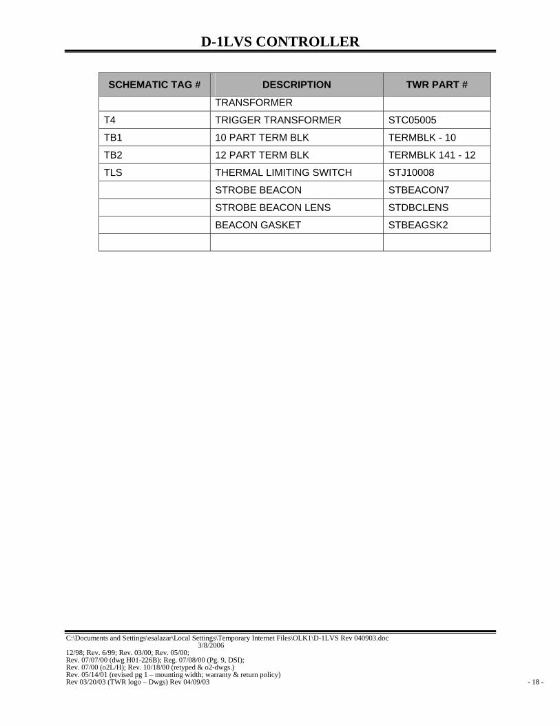
SCHEMATIC TAG # DESCRIPTION TWR PART #
TRANSFORMER
T4 TRIGGER TRANSFORMER STC05005
TB1 10 PART TERM BLK TERMBLK - 10
TB2 12 PART TERM BLK TERMBLK 141 - 12
TLS THERMAL LIMITING SWITCH STJ10008
STROBE BEACON STBEACON7
STROBE BEACON LENS STDBCLENS
BEACON GASKET STBEAGSK2

D-1LVS CONTROLLER
C:\Documents and Settings\esalazar\Local Settings\Temporary Internet Files\OLK1\D-1LVS Rev 040903.doc 3/8/2006 12/98; Rev. 6/99; Rev. 03/00; Rev. 05/00; Rev. 07/07/00 (dwg H01-226B); Reg. 07/08/00 (Pg. 9, DSI); Rev. 07/00 (o2L/H); Rev. 10/18/00 (retyped & o2-dwgs.) Rev. 05/14/01 (revised pg 1 – mounting width; warranty & return policy) Rev 03/20/03 (TWR logo – Dwgs) Rev 04/09/03 - 19 -
7.0 RECOMMENDED SPARE PARTS LIST
QUANTITY PART NUMBER DESCRIPTION
1 STH01226B D-1LVS PRINTED CIRCUIT BOARD
1 STJ10006 DPDT CONTACTOR RELAY
1 STFLSHTB5 STROBE FLASHTUBE
1 P2455L PHOTOCELL
2 KTK10 10 amp FUSE
2 FLQ18 1/8 amp FUSE
2 FUSE .5 1/2 amp FUSE
1 X9KE SPDT RELAY
2 X99KE DPDT RELAY


1
1
2
2
3
3
4
4
A A
B B
SHEET 1 OF 1
DRAWN
CHECKED
QA
MFG
APPROVED
jbustamante 7/26/2007
DWG NO
100437i_RA
TITLE
SIZE
BSCALE
REV
A
Enlightened TechnologyTWR Lighting, Inc.
Parts List
DESCRIPTIONPART NUMBERQTYITEM
DB QUICK OPEN SCREW FLAT RECEP12110201311
#16AWG BLACK TEFLON TYPE EE M#16AWGBLK12
INDUCTOR .47MH TRANSFORMER 2INDCTRC300113
TRIGGER TRANSFORMER 25KVSTC0500514------5
FLASHTUBE SOCKET INSERT T&BBU2720036------7
8-32 X 1/4 304 S/S PHILLIPS PA832X14PHH28
6-32 X 3/8 304 S/S PHILLIPS PA632X38PHH29
10-32 X 3/8 304 S/S PHIL HD CAPT1032X38PHW1010
RAD18277 T&B CONNECTOR18RAD18277211
GASKET NEOPRENE 13 1/4 X 15STBEAGSK2112
HI TEMP TY WRAPS T&B TEFZELTYZ23M1513
CLEAR DB LENSSTDBCLENS114
PRODUCT LABELSTCONLAB2115
1/8 X .400 SS POP RIVET #4418PRSS-2816
HOL 1/16 HOL 7X7 S.S. WI7X7SS1.7517
#360 CIRCULAR SPIRIT LEVEL2-10000118
1/4 FW CH16L 18-8 .265 ID/.514FWDB219
SHORT STROBE BEACON FRAME KITSTBFRAMKIT120
DUAL BEACON LENS RETAINER RING100337220A
DUAL BEACON CAP BRACKET100368620B
INDUCTOR BRACKET100396120C
DUAL BEACON SAFETY BRACKET100395M120D
CAP DUAL BEACON100344120E
DUAL BEACON UPPER HINGE ASSEMBLY100342120F
DUAL BEACON BASE100393-01M120G
#18AWG TEFLON TYPE EE BLUE M118AWG BLU221
#18AWG TEFLON TYPE EE BROWN M118AWG BRN222
DB QUICK OPEN CAPTIVE SCRES S/121340712123
#8 NYLON FLAT WASHER8NFW824
1/4 X 3/4 S/S SHORT CLEVIS PIN14X34CLVP225
1/2" S/S COTTER PIN12SSCP226
12-6-1 S/S RETAINER FOR QUICK OPEN1261127
CHERRY SWITCH, #E69-00ASTJ02003128
1" 90 DEGREE SHORT ELBOW GALVEL190S129
1" NPT CORD CONNECTOR .700 TO .984CC-MPT-1-G130
INDUCTOR BOTOM PAD GASKET100394-02131
FLSHTB 47.8Q30-3 2 TURN HELIXSTFLSHTB5132
1" CONDUIT LOCKNUT GALVANIZEDA315133
A325 5/8 X 1-1/2 BOLT W/ANCO L/NUT58X112434
#10 304 S/S FLAT WASHER1032FW635
8-32 X 5/8 304 S/S PHIL. PAN HEAD SCREW832X58PHH336
GASKET NEOPRENE 3/16 X 15 1/4STBEAGSKT137
DUAL BEACON FLASHTUBE SOCKET100319138
10-32X1/2 304 S/S PHILLIPS BIN1032X12PHH639
8-32 X 1/2 304 PHILLIPS PAN HEAD832X12PHH440
1/2" GLUE BASE HEAT SHRINKHEATSHRINK2141
1/16 COPPER SLEEVECSL062X100442
#16AWG RED TEFLON TYPE EE M16816AWG RED143
1/4" BLACK FIT 221-1/4BLK-100HEATSHRINK11544
STAKON (RB2237 BULK)14RB8FL245
TY WRAP ANCHOR 23N3669TYANCHOR146
7 POLE HIGH BARRIER TERM. BLOCK621 RZ 07147
TERMARKSTRIP 7 POSITION MARATMS621XP07148
14-16 AWG 6 LOCKING FORK T&B14RB-6FL849
BULK RA2217 22-18 AWG18RA6FL550
10-12 AWG #8 LOCKING FORK T&BKV10-8F-D251
NON-OEM PARTS WARNING LABEL DNONOEMLBL152
BULK RB877 P&B (BULK)14RB10R353
5/16 X 1/4 ROUND S/S SPACER115510SSO354
6-32 X 1/4 PH PH SCREW632X14PHH155
20E
16
20B
10
12
18
32
28
116
55
3938
36
20F
2526
19
4
20G
8
37
27
16
31
34
30
33
29
40
20C
352
15
9
17
48
35
40
24
20A
14
16
47
8
42
L-865 STROBE BEACON ASSEMBLY DETAIL(STBEACON7)
55
46
=ITEMS NOT SHOWN*
*
*
***
***
**
*
*
*
SEENOTE
#1
NOTE:1. ITEM #20A-#20G SOLD AS AN ASSEMBLY ONLY. ORDER ITEM PART #STBFRAMKIT.
23
ASSEMBLY VIEW
1
20D
10