D125B Dual Class B Initiating Module - Bosch...
16
Dual Class B Initiating Module D125B en Installation Instructions
Transcript of D125B Dual Class B Initiating Module - Bosch...
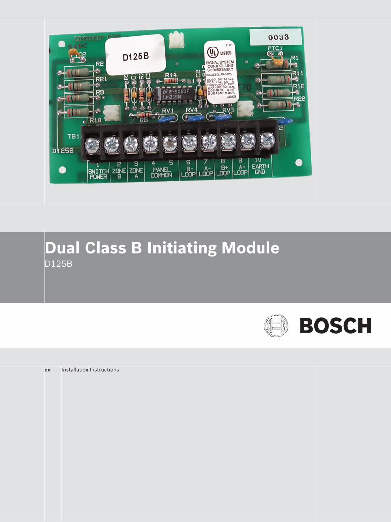
Dual Class B Initiating ModuleD125B
en Installation Instructions

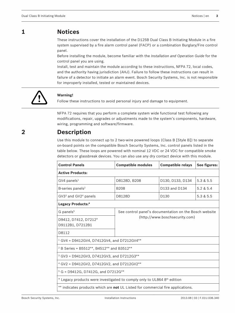
NoticesThese instructions cover the installation of the D125B Dual Class B Initiating Module in a firesystem supervised by a fire alarm control panel (FACP) or a combination Burglary/Fire controlpanel.Before installing the module, become familiar with the Installation and Operation Guide for thecontrol panel you are using.Install, test and maintain the module according to these instructions, NFPA 72, local codes,and the authority having jurisdiction (AHJ). Failure to follow these instructions can result infailure of a detector to initiate an alarm event. Bosch Security Systems, Inc. is not responsiblefor improperly installed, tested or maintained devices.
!Warning!
Follow these instructions to avoid personal injury and damage to equipment.
NFPA 72 requires that you perform a complete system wide functional test following anymodifications, repair, upgrades or adjustments made to the system’s components, hardware,wiring, programming and software/firmware.
DescriptionUse this module to connect up to 2 two‑wire powered loops (Class B [Style B]) to separateon‑board points on the compatible Bosch Security Systems, Inc. control panels listed in thetable below. These loops are powered with nominal 12 VDC or 24 VDC for compatible smokedetectors or glassbreak devices. You can also use any dry contact device with this module.
Control Panels Compatible modules Compatible relays See figures:
Active Products:
GV4 panels1 D8128D, B208 D130, D133, D134 5.3 & 5.5
B-series panels2 B208 D133 and D134 5.2 & 5.4
GV33 and GV24 panels D8128D D130 5.3 & 5.5
Legacy Products:*
G panels5 See control panel’s documentation on the Bosch website(http://www.boschsecurity.com)
D9412, D7412, D7212*D9112B1, D7212B1
D8112
1 GV4 = D9412GV4, D7412GV4, and D7212GV4**
2 B Series = B5512**, B4512** and B3512**
3 GV3 = D9412GV3, D7412GV3, and D7212G3**
4 GV2 = D9412GV2, D7412GV2, and D7212GV2**
5 G = D9412G, D7412G, and D7212G**
* Legacy products were investigated to comply only to UL864 8th edition
** indicates products which are not UL Listed for commercial fire applications.
1
2
Dual Class B Initiating Module Notices | en 3
Bosch Security Systems, Inc. Installation Instructions 2013.08 | 03 | F.01U.036.340

Figure 2.1: D125B powered loop interface module
1 Power-limited, supervised switchedauxiliary power (detector reset)
7 Power-limited, supervised negative toA loop detectors
2 Supervised connection to protectivezone or point on the control panel
8 Power-limited, supervised positive to Bloop detectors
3 Supervised connection to protectivezone or point on the control panel
9 Power-limited, supervised positive to Aloop detectors
4 Connect to only one common at thepanel
10 Earth ground
5 Connect to only one common on thecontrol panel
11 Mounting holes
6 Power-limited, supervised negative toB loop detectors
OperationThe module can be powered from the control panel’s switched auxiliary power output or froman external auxiliary power supply. Currently, the control panels can only supply 12 VDC, butexternal power supplies can provide either 12 VDC or 24 VDC.For wiring details, see Wiring, page 6.
Power from the control panelIn this mode, the control panel switched auxiliary power output supplies regulated,power‑limited, supervised 12 VDC power to the module. The switched power output allows alldetectors connected to the module to be reset by interrupting power using the Reset Sensorcommand. See Wiring for 12 VDC power supplied by the control panel, page 7.
3
3.1
4 en | Notices Dual Class B Initiating Module
2013.08 | 03 | F.01U.036.340 Installation Instructions Bosch Security Systems, Inc.

Power from an external auxiliary power supplyUse a separate power supply listed for fire signaling units and/or commercial or residentialburglary units. Depending on compatibility with the control panel, a D130, D133, or D134Relay can be required to reset the smoke detectors using the Reset Sensor command. SeeWiring for 12 VDC or 24 VDC power supplied by an external power supply, page 8.The external power supply must be UL1481 or UL864 Listed, regulated, and power‑limited.Install the control panel and external power supply in the same room no more than 20 ft (6 m)apart. The interconnecting wires between the control panel and external power supply mustbe in conduit.The power source for both the auxiliary power supply and the control panel must be from thesame dedicated AC branch circuit.
InstallationThe module can be mounted in the D8103, D8108A, D8109, D8109G, D8109H, or D8109LEnclosures. Only the D8108A and D8109 models are suitable for commercial fire applications.The D8108A and D8109L enclosures require use of a D137 Mounting Bracket to install themodule. The other enclosures have several module mounting locations to which the modulecan be installed using the supplied screws. Refer to the D137’s and the enclosure’sInstallation Instructions for mounting locations and instructions.
3.2
4
Dual Class B Initiating Module Notices | en 5
Bosch Security Systems, Inc. Installation Instructions 2013.08 | 03 | F.01U.036.340

Wiring
Wiring sensor loopsThe D125B has two loop inputs:
Loop A Loop B
A+ (terminal 9) B+ (terminal 8)
A- (terminal 7) B- (terminal 6)
Notice!
Observe polarity when wiring detection loops. Do not cross Loop A and Loop B connections.
To supervise the loops, install an end-of-line (EOL) resistor after the last detector of eachprotective loop. When installing a D125B in a new or existing system, use the 1.8 kΩ EOLresistor (P/N: F01U009011B) supplied with the module.
Notice!
To ensure system supervision, do not use looped wire under the terminals. Break the run to
provide supervision of the connections.
Figure 5.1: D125B loop wiring
1 Normally‑closed contacts (NC) 4 Point input terminal
2 Normally‑open contacts (NO) 5 Common
3 Combination: Normally‑open andnormally‑closed contacts (NO/NC)
6 1.8 kΩ EOL resistor (P/N: F01U009011B) supplied with themodule
The D125B shorts the protective loop on the control panel when the high (+) and low (-) sideof either module loop is shorted together or when a smoke detector activates. The moduleopens the protective loop on the control panel during the following conditions:– The module protective loop is opened.– The D125B is not powered.– Either the high (+) side of the loop or the low (-) side of the loop is shorted to ground.
5
5.1
6 en | Notices Dual Class B Initiating Module
2013.08 | 03 | F.01U.036.340 Installation Instructions Bosch Security Systems, Inc.

For control panels with Ground Fault Detect, a short to ground causes a ground faultcondition when Ground Fault Detect is enabled.When programming for fire applications, refer to the corresponding control panel operationand installation guide.
Wiring for 12 VDC power supplied by the control panel
Wiring B Series panels
Figure 5.2: Wiring two‑wire loops powered by a B Series control panel
1 Power‑limited, supervised switchedauxiliary power from Output A (NC) ofthe control panel1
7 Power-limited, supervised negative toA loop detectors (see Wiring sensorloops, page 6)
2 Supervised connection to Zone Bpower from an on‑board point of thepanel
8 Power-limited, supervised positive to Bloop detectors (see Wiring sensorloops, page 6)
3 Supervised connection to Zone Apower from an on‑board point of thepanel
9 Power-limited, supervised positive to Aloop detectors (see Wiring sensorloops, page 6)
4 Connection with terminal 5 to only onecommon on the panel
10 Earth ground
5 Connection with terminal 4 to only onecommon on the panel
11 Output A jumper (under cover) set forauxiliary power applications (AUXPWR)
6 Power-limited, supervised negative toB loop detectors (see Wiring sensorloops, page 6)
1 You can also use output B or C in conjunction with a D133 or D134 relay module.
5.2
5.2.1
Dual Class B Initiating Module Notices | en 7
Bosch Security Systems, Inc. Installation Instructions 2013.08 | 03 | F.01U.036.340

Wiring G Series panels
Figure 5.3: Wiring two‑wire loops powered by a G Series panel
1 Power‑limited, supervised switchedauxiliary power from the controlpanel’s relay C
6 Power-limited, supervised negative toB loop detectors (see Wiring sensorloops, page 6)
2 Supervised connection to Zone Bpower from an on‑board point of thepanel
7 Power-limited, supervised negative toA loop detectors (see Wiring sensorloops, page 6)
3 Supervised connection to Zone Apower from an on‑board point of thepanel
8 Power-limited, supervised positive to Bloop detectors (see Wiring sensorloops, page 6)
4 Connection with terminal 4 to only onecommon on the panel
9 Power-limited, supervised positive to Aloop detectors (see Wiring sensorloops, page 6)
5 Connection with terminal 5 to only onecommon on the panel
10 Earth ground
Wiring for 12 VDC or 24 VDC power supplied by an externalpower supplyUse either a 12 VDC or 24 VDC regulated, power‑limited auxiliary power supply listed underUL864 or UL1481.
Notice!
Do not mix 12 VDC and 24 VDC detectors on the same module.
5.2.2
5.3
8 en | Notices Dual Class B Initiating Module
2013.08 | 03 | F.01U.036.340 Installation Instructions Bosch Security Systems, Inc.

Wiring B Series panels
Figure 5.4: Wiring two‑wire loops for power supplied by an external auxiliary power supply controlled by a relay and a B Series
panel
1 Power‑limited, supervised switchedauxiliary power from Output A (NC) ofthe control panel1
9 Power-limited, supervised positive to Aloop detectors (see Wiring sensorloops, page 6)
2 Supervised connection to Zone Bpower from an on‑board point of thepanel
10 Earth ground
3 Supervised connection to Zone Apower from an on‑board point of thepanel
11 Output A (NC) of the control panelcontrols the relay
4 Connection with terminal 5 to only onecommon on the panel
12 For 24 V applications, cut this wire
5 Connection with terminal 4 to only onecommon on the panel
13 Negative connection from the auxiliarypower supply to the negative terminalof the relay and panel common
6 Power-limited, supervised negative toB loop detectors (see Wiring sensorloops, page 6)
14 Positive connection from the auxiliarypower supply to the positive terminalsof the relay
5.3.1
Dual Class B Initiating Module Notices | en 9
Bosch Security Systems, Inc. Installation Instructions 2013.08 | 03 | F.01U.036.340

7 Power-limited, supervised negative toA loop detectors (see Wiring sensorloops, page 6)
15 UL Listed regulated, power limitedauxiliary power supply (12 VDC or24 VDC) for fire protection systems
8 Power-limited, supervised positive to Bloop detectors (see Wiring sensorloops, page 6)
16 Output A jumper (under cover) set forauxiliary power applications (AUXPWR)
1 You can also use output B or C in conjunction with a D133 or D134 relay module
10 en | Notices Dual Class B Initiating Module
2013.08 | 03 | F.01U.036.340 Installation Instructions Bosch Security Systems, Inc.

Wiring G Series panels
Figure 5.5: Wiring two‑wire loops for power supplies by an external auxiliary power supply controlled by a relay and a G Series
panel
1 Power‑limited, supervised switchedauxiliary power from the switchingrelay
9 Power-limited, supervised positive to Aloop detectors (see Wiring sensorloops, page 6)
2 Supervised connection to Zone Bpower from an on‑board point of thepanel
10 Earth ground
3 Supervised connection to Zone Apower from an on‑board point of thepanel
11 Power‑limited, supervised switchedauxiliary power from the controlpanel’s relay C to the switching relay
4 Connection with terminal 5 to only onecommon on the panel
12 For 24 V applications, cut this wire
5 Connection with terminal 4 to only onecommon on the panel
13 Negative connection from the auxiliarypower supply to the negative terminalof the relay and panel common
6 Power-limited, supervised negative toB loop detectors (see Wiring sensorloops, page 6)
14 Positive connection from the auxiliarypower supply to the positive terminalsof the relay
7 Power-limited, supervised negative toA loop detectors (see Wiring sensorloops, page 6)
15 UL Listed regulated, power‑limitedauxiliary power supply (12 VDC or24 VDC) for fire protection systems
8 Power-limited, supervised positive to Bloop detectors (see Wiring sensorloops, page 6)
5.3.2
Dual Class B Initiating Module Notices | en 11
Bosch Security Systems, Inc. Installation Instructions 2013.08 | 03 | F.01U.036.340

SpecificationsElectrical
12 VDC 24 VDC
Nominal operating voltage Supplied by the control panelor by a regulated,power‑limited 12 VDC powersupply listed under UL864 orUL1481
Supplied by a regulated,power-limited 24 V powersupply listed under UL864 orUL1481
Alarm Current (maximum)
– One loop only 75 mA 168 mA
– Both loops 145 mA 300 mA
Standby Current (maximum)
– One loop only 12 mA 25 mA
– Both loops 24 mA 50 mA
Electrical – two‑wire powered loop Class B (Style B)
Current 12 VDC 24 VDC
– Alarm > 11.8 mA > 24.1 mA
– Detector 3 mA 7 mA
– Trouble < 3.5 mA < 7.5 mA
Loop wire resistance 50 Ω 50 Ω
Environmental
Environment Indoor, dry
Operating Temperature +32°F to +122°F (0°C to +50°C)
Relative Humidity 5% to 93% at +86°F (+30°C); non-condensing
Fire/Control Panel Cabling
Maximum Wire Resistance 2 Ω
Maximum distance per wire size
Maximum distance Wire size
60 ft (15 m) 22 AWG (0.34 mm2)
160 ft (40 m) 18 AWG (0.75 mm2)
Mechanical
Dimensions (H x W x D) 5 in. x 3 in. x 0.8 in. (12.7 cm x 7.6 cm x 2.0 cm)
6
12 en | Notices Dual Class B Initiating Module
2013.08 | 03 | F.01U.036.340 Installation Instructions Bosch Security Systems, Inc.

Compatible detectors and modules
Compatible 2‑wire detectorsUnderwriters Laboratories (UL) has found the following 2‑wire detectors to be compatiblewith the D125B:
Manufacturer CTN Series Base Reversing* Maximum numberof detectors per
loop
12 V 24 V
Bosch D263 D263 N/A 8 8
D263TH 8 8
D263THC 8 8
D263THS ● 8 8
D285 D285 D287,D288,D340
10 10
D285TH 10 10
F220-P F220 F220-B6 8 8
F220-PTH 8 8
F220-PTHC 8 8
F220-135 8 8
F220-135F 8 8
F220-190F 8 8
System Sensor 2W-B i3 N/A 8 8
2WTA-B 8 8
2WT-B 8 8
5151 100 B110LP 10 10
* D132A does not operate at 24 V; use only on 12 V powered loops.
7
7.1
Dual Class B Initiating Module Notices | en 13
Bosch Security Systems, Inc. Installation Instructions 2013.08 | 03 | F.01U.036.340

Compatible modulesUnderwriters Laboratories (UL) has found the following modules to be compatible with theD125B:
CTN Manufacturer 12 V 24 V Reversing*
D130 Bosch ● ●
D132A reversing relay* ● ●
D133 ● **
D134 ● **
* D132A does not operate at 24 V; use only on 12 V powered loops.
** Relay can switch 24 V, but operates at 12 V.
7.2
14 en | Notices Dual Class B Initiating Module
2013.08 | 03 | F.01U.036.340 Installation Instructions Bosch Security Systems, Inc.


Bosch Security Systems, Inc.
130 Perinton Parkway
Fairport, NY 14450
USA
www.boschsecurity.com
© Bosch Security Systems, Inc., 2013