D115 Quick Start Guide - Servo Dynamics · D115 Quick Start Guide And Host Software Guide Benjamin...
19
Document Number 3500500050 Rev- D115 Quick Start Guide And Host Software Guide Benjamin Paik 5/14/2014 Abstract - This manual describes how to get the D115 up and running. Each section of the host software is discussed. Users will be able to configure and tune the D115 controller to control Brushless, Brush, and voice coil motors.
Transcript of D115 Quick Start Guide - Servo Dynamics · D115 Quick Start Guide And Host Software Guide Benjamin...
Document Number 3500500050 Rev-
D115 Quick Start Guide
And Host Software Guide
Benjamin Paik
5/14/2014
Abstract - This manual describes how to get the D115 up and running. Each section of the host software
is discussed. Users will be able to configure and tune the D115 controller to control Brushless, Brush,
and voice coil motors.
D115 Quick Start and Host Guide 3500500050 Rev- Page 1
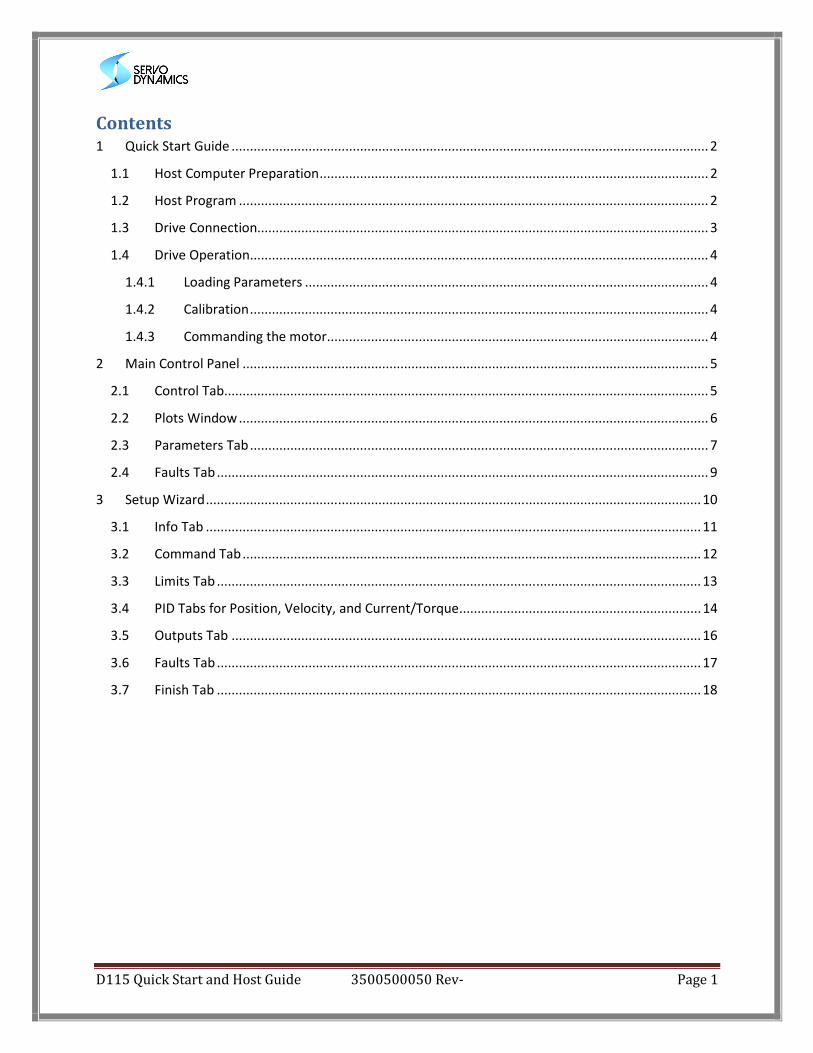
Contents 1 Quick Start Guide .................................................................................................................................. 2
1.1 Host Computer Preparation .......................................................................................................... 2
1.2 Host Program ................................................................................................................................ 2
1.3 Drive Connection........................................................................................................................... 3
1.4 Drive Operation ............................................................................................................................. 4
1.4.1 Loading Parameters .............................................................................................................. 4
1.4.2 Calibration ............................................................................................................................. 4
1.4.3 Commanding the motor ........................................................................................................ 4
2 Main Control Panel ............................................................................................................................... 5
2.1 Control Tab .................................................................................................................................... 5
2.2 Plots Window ................................................................................................................................ 6
2.3 Parameters Tab ............................................................................................................................. 7
2.4 Faults Tab ...................................................................................................................................... 9
3 Setup Wizard ....................................................................................................................................... 10
3.1 Info Tab ....................................................................................................................................... 11
3.2 Command Tab ............................................................................................................................. 12
3.3 Limits Tab .................................................................................................................................... 13
3.4 PID Tabs for Position, Velocity, and Current/Torque .................................................................. 14
3.5 Outputs Tab ................................................................................................................................ 16
3.6 Faults Tab .................................................................................................................................... 17
3.7 Finish Tab .................................................................................................................................... 18
D115 Quick Start and Host Guide 3500500050 Rev- Page 2
1 Quick Start Guide The Host program with USB connection is required to communicate with the controller and set
configuration parameters. The installation and setup is as follows
1.1 Host Computer Preparation
• The Host program is a Java program and requires that Java 7 be installed. Java 7 can be
downloaded and installed free from www.java.com.
• The USB connection requires Visual C++ drivers which are included with the “Microsoft Visual
C++ 2012 Redistributable Package”. This can be downloaded and installed free from Microsoft.
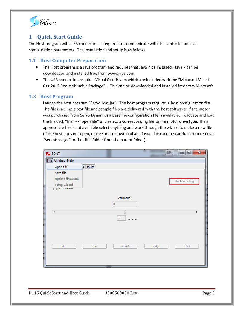
1.2 Host Program
Launch the host program “ServoHost.jar”. The host program requires a host configuration file.
The file is a simple text file and sample files are delivered with the host software. If the motor
was purchased from Servo Dynamics a baseline configuration file is available. To locate and load
the file click “file” -> “open file” and select a corresponding file to the motor drive type. If an
appropriate file is not available select anything and work through the wizard to make a new file.
(If the host does not open, make sure to download and install Java and be careful not to remove
“ServoHost.jar” or the “lib” folder from the parent folder).
D115 Quick Start and Host Guide 3500500050 Rev- Page 3
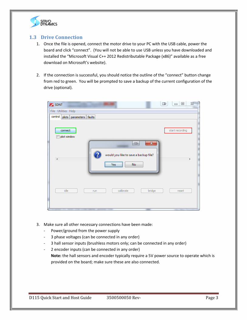
1.3 Drive Connection
1. Once the file is opened, connect the motor drive to your PC with the USB cable, power the
board and click “connect”. (You will not be able to use USB unless you have downloaded and
installed the “Microsoft Visual C++ 2012 Redistributable Package (x86)” available as a free
download on Microsoft’s website).
2. If the connection is successful, you should notice the outline of the “connect” button change
from red to green. You will be prompted to save a backup of the current configuration of the
drive (optional).
3. Make sure all other necessary connections have been made:
- Power/ground from the power supply
- 3 phase voltages (can be connected in any order)
- 3 hall sensor inputs (brushless motors only; can be connected in any order)
- 2 encoder inputs (can be connected in any order)
Note: the hall sensors and encoder typically require a 5V power source to operate which is
provided on the board; make sure these are also connected.
D115 Quick Start and Host Guide 3500500050 Rev- Page 4
1.4 Drive Operation
This section assumes the drive is successfully connected to a motor and to the host program. In order to
operate the drive the controller must be loaded with an appropriate parameter file and a calibration
run.
1.4.1 Loading Parameters
If the drive is being configured for the first time and the motor has been purchased from Servo
Dynamics there is a configuration file supplied with the drive. This file should be the file used to open
the host. Once the parameter file is in the host it can be loaded into the drive. This is detailed in
sections 2.3 using the setup wizard. The settings are viewable via the wizard and loaded via the last tab
where the parameters are sent. A more advanced and direct way is also possible from the parameters
tab and this is discussed in section 3.7.
1.4.2 Calibration
The drive must learn the motor connections. Clicking on the calibrate button the controller will go into a
sequence which will exercise the motor and observe the states of the Hall signals and the encoder. The
drive algorithm determines their order and configures the drive to operate with them. Once this is done
the drive will operate.
1.4.3 Commanding the motor
The Host Software assumes control of the motor and will run via the USB communication. The drive
must see a transition from “idle” to “run” to enable the drive. Therefore select idle and then run. The
drive will enable and the command will be generated via the scroll bar. The host defaults to mode 0.
The configuration file determines what mode 0 means. If it is position the motor will servo to the
commanded position, if it is velocity the controller will command the motor to a velocity and so on. See
section 2.1 for more detail on the control tab.
To switch over to run the controller via the I/O on the controller go to idle and then select the bridge
button. Transition the enable switch from off to enable to operate from the controller.
Adjust or make new configurations via the setup wizard and re-download until satisfied with
performance.
D115 Quick Start and Host Guide 3500500050 Rev- Page 5
2 Main Control Panel
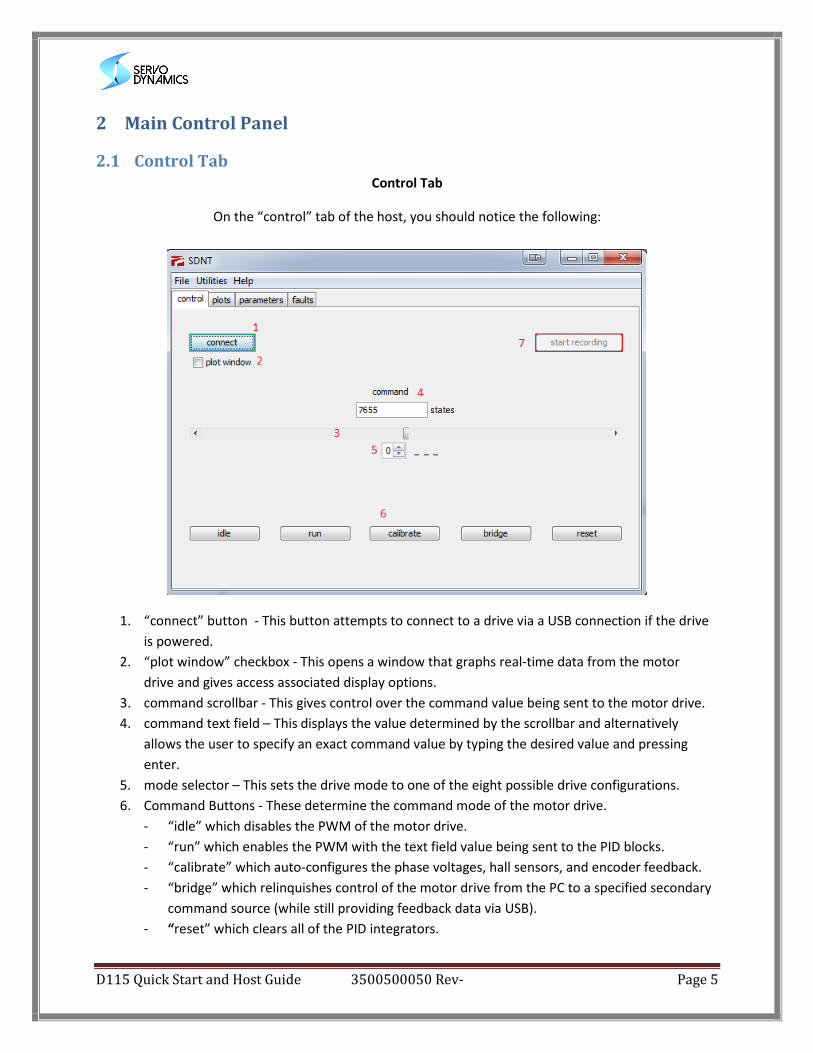
2.1 Control Tab
Control Tab
On the “control” tab of the host, you should notice the following:
1. “connect” button - This button attempts to connect to a drive via a USB connection if the drive
is powered.
2. “plot window” checkbox - This opens a window that graphs real-time data from the motor
drive and gives access associated display options.
3. command scrollbar - This gives control over the command value being sent to the motor drive.
4. command text field – This displays the value determined by the scrollbar and alternatively
allows the user to specify an exact command value by typing the desired value and pressing
enter.
5. mode selector – This sets the drive mode to one of the eight possible drive configurations.
6. Command Buttons - These determine the command mode of the motor drive.
- “idle” which disables the PWM of the motor drive.
- “run” which enables the PWM with the text field value being sent to the PID blocks.
- “calibrate” which auto-configures the phase voltages, hall sensors, and encoder feedback.
- “bridge” which relinquishes control of the motor drive from the PC to a specified secondary
command source (while still providing feedback data via USB).
- “reset” which clears all of the PID integrators.
D115 Quick Start and Host Guide 3500500050 Rev- Page 6
7. record button – This button becomes enabled by creating a data file (clicking “create data file”
from the “Utilities” drop down menu). Clicking the button once will begin saving all data
received over USB to the data file created. Clicking the button a second time will stop recording
data. The data file will not be readable as is and must be processed before it can be imported
into excel or some other analysis tool (click “process data file” from the “Utilities” drop down
menu and select the data file to create a readable file format).
Note: the command text field, scrollbar, buttons, and mode selector will be disabled until a valid .txt file
has been opened.
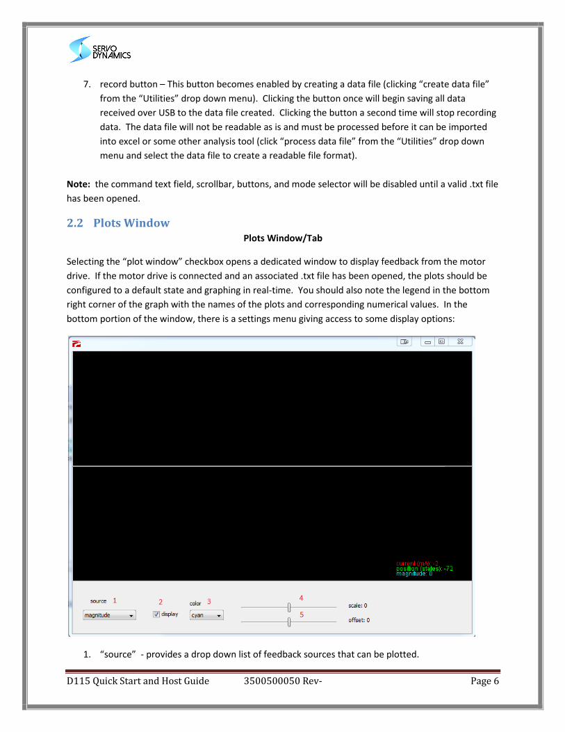
2.2 Plots Window
Plots Window/Tab
Selecting the “plot window” checkbox opens a dedicated window to display feedback from the motor
drive. If the motor drive is connected and an associated .txt file has been opened, the plots should be
configured to a default state and graphing in real-time. You should also note the legend in the bottom
right corner of the graph with the names of the plots and corresponding numerical values. In the
bottom portion of the window, there is a settings menu giving access to some display options:
1. “source” - provides a drop down list of feedback sources that can be plotted.
D115 Quick Start and Host Guide 3500500050 Rev- Page 7
2. “display” - determines if the selected feedback source will be graphed.
3. “color” - provides a drop down list of colors for the selected feedback source.
4. “scale” - slider which vertically rescales the selected plot to zoom in or out.
5. “offset” - slider which re-centers the plot on the graph.
In addition to the “plots window”, there is also a “plots” tab which graphs feedback if the “plots
window” checkbox is not selected in the “control” tab. The graphing in the “plots” tab is essentially the
same as in the popup window (with graph names and values shown in the bottom-right corner) except
that the screen is not resizable and there are no display options (though settings changes made in the
popup plots window will transfer over to the “plots” tab)
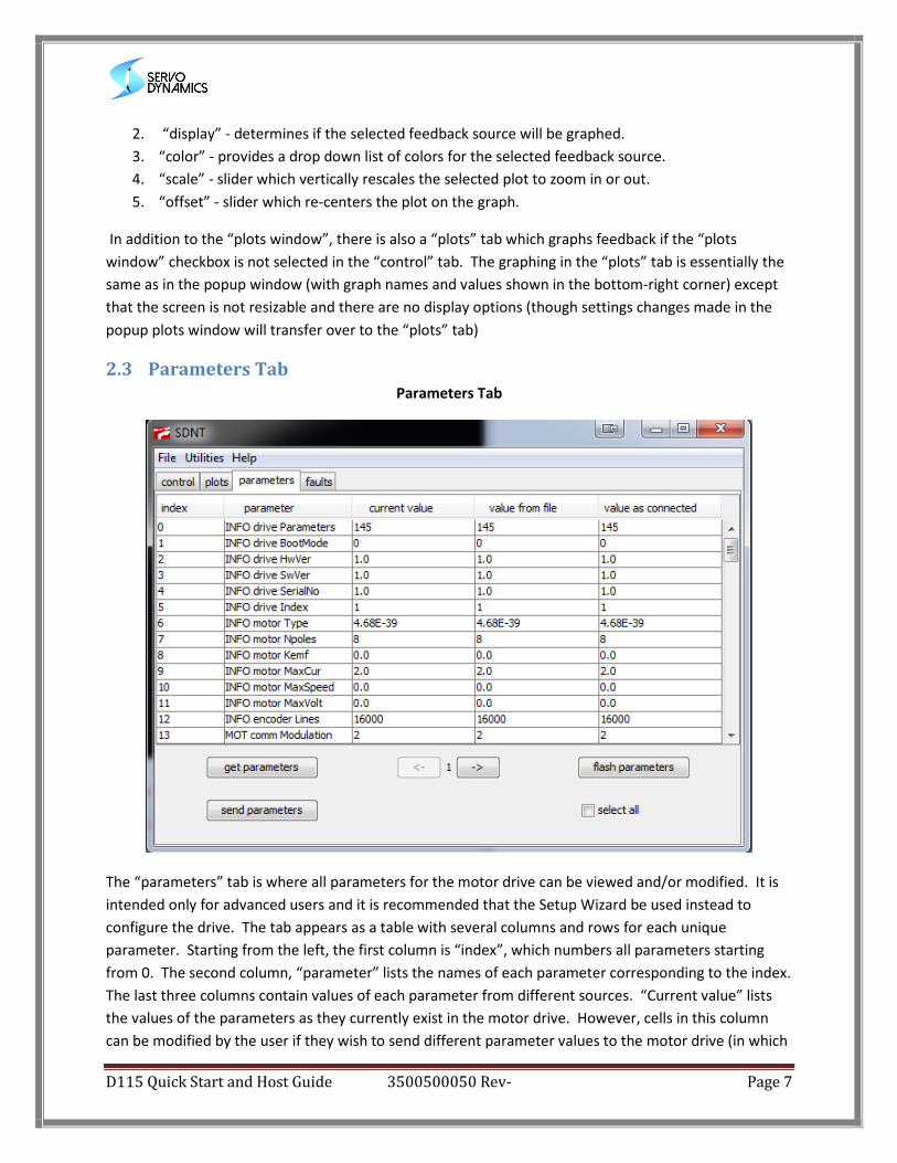
2.3 Parameters Tab
Parameters Tab
The “parameters” tab is where all parameters for the motor drive can be viewed and/or modified. It is
intended only for advanced users and it is recommended that the Setup Wizard be used instead to
configure the drive. The tab appears as a table with several columns and rows for each unique
parameter. Starting from the left, the first column is “index”, which numbers all parameters starting
from 0. The second column, “parameter” lists the names of each parameter corresponding to the index.
The last three columns contain values of each parameter from different sources. “Current value” lists
the values of the parameters as they currently exist in the motor drive. However, cells in this column
can be modified by the user if they wish to send different parameter values to the motor drive (in which
D115 Quick Start and Host Guide 3500500050 Rev- Page 8
case the value will be different than the parameter value currently in the motor drive). “Value from file”
lists the values of the parameters as they exist in the most recently opened text file (these cells cannot
be modified). “Value as connected” lists the values of the parameters in the motor drive when it was
first connected to host (these cells cannot be modified). This allows the user to observe changes
between the current and original parameter values. To help the user observe and track parameter
modifications, cells in any of the three parameter value columns will be highlighted in yellow if they are
different from the current parameter values in the motor drive. More details of the parameter tab are
described below:
- The “get parameters” button retrieves all the current parameter values from the motor
drive and fills the “current value” column accordingly.
- Parameters can be modified by changing values in the “current value” column and clicking
“send parameters”. (All parameters that have been changed will be highlighted in yellow
until they are sent to the motor drive.)
- The “flash parameters” button writes all the parameter values (as they currently exist in the
motor drive) to flash. This means that these parameter values will remain in the motor
drive even after it has been powered down (and will be the active parameter values
whenever the motor drive is powered on).
- Up to 100 parameters are shown per page. The parameter page can be changed by clicking
on the page arrows at the bottom of the parameter tab.
- Each of the column headers in the parameter table (except for “current value”) are actually
buttons, each with unique effects.
- “Index” and “parameter” column headers both affect the ordering of the parameter table.
Clicking “index” organizes the parameters by index while “parameter” organizes the
parameters alphabetically.
- Selecting parameter(s) will highlight them in blue. Clicking “value from file” or “value as
connected” will transfer values from these columns to the “current value” column for each
selected row. (Non-contiguous row selections can be made by holding the “Ctrl” key while
clicking/dragging the mouse cursor).
- The “select all” checkbox selects all rows on every page, easing the process of transferring
parameter values from the “value from file” or “value as connected” columns.
D115 Quick Start and Host Guide 3500500050 Rev- Page 9
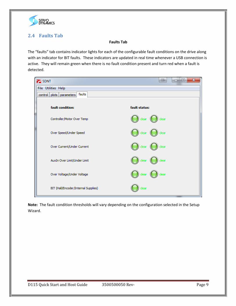
2.4 Faults Tab
Faults Tab
The “faults” tab contains indicator lights for each of the configurable fault conditions on the drive along
with an indicator for BIT faults. These indicators are updated in real time whenever a USB connection is
active. They will remain green when there is no fault condition present and turn red when a fault is
detected.
Note: The fault condition thresholds will vary depending on the configuration selected in the Setup
Wizard.
D115 Quick Start and Host Guide 3500500050 Rev- Page 10
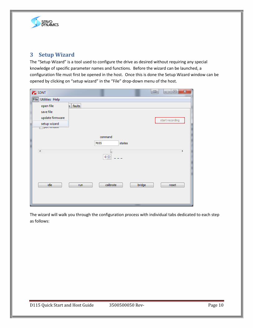
3 Setup Wizard The “Setup Wizard” is a tool used to configure the drive as desired without requiring any special
knowledge of specific parameter names and functions. Before the wizard can be launched, a
configuration file must first be opened in the host. Once this is done the Setup Wizard window can be
opened by clicking on “setup wizard” in the “File” drop-down menu of the host.
The wizard will walk you through the configuration process with individual tabs dedicated to each step
as follows:
D115 Quick Start and Host Guide 3500500050 Rev- Page 11
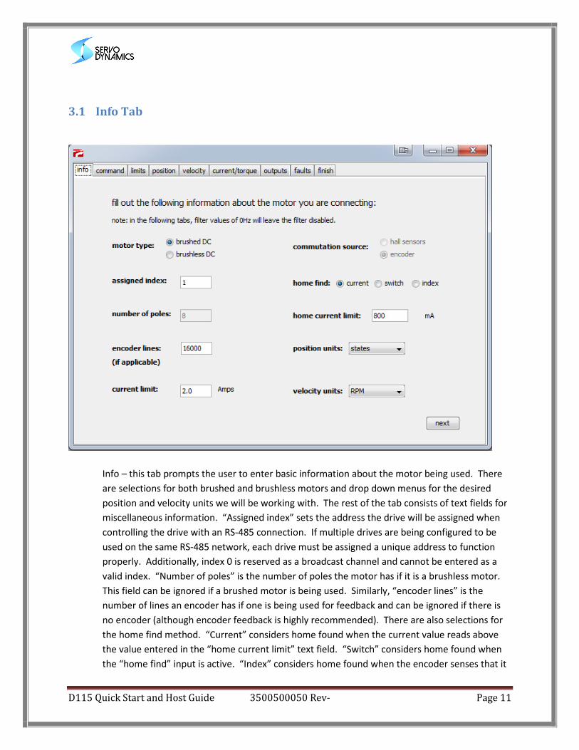
3.1 Info Tab
Info – this tab prompts the user to enter basic information about the motor being used. There
are selections for both brushed and brushless motors and drop down menus for the desired
position and velocity units we will be working with. The rest of the tab consists of text fields for
miscellaneous information. “Assigned index” sets the address the drive will be assigned when
controlling the drive with an RS-485 connection. If multiple drives are being configured to be
used on the same RS-485 network, each drive must be assigned a unique address to function
properly. Additionally, index 0 is reserved as a broadcast channel and cannot be entered as a
valid index. “Number of poles” is the number of poles the motor has if it is a brushless motor.
This field can be ignored if a brushed motor is being used. Similarly, “encoder lines” is the
number of lines an encoder has if one is being used for feedback and can be ignored if there is
no encoder (although encoder feedback is highly recommended). There are also selections for
the home find method. “Current” considers home found when the current value reads above
the value entered in the “home current limit” text field. “Switch” considers home found when
the “home find” input is active. “Index” considers home found when the encoder senses that it
D115 Quick Start and Host Guide 3500500050 Rev- Page 12
has passed the index marker. Lastly, “maximum current” sets the cycle-by-cycle current limit of
the drive in Amps.
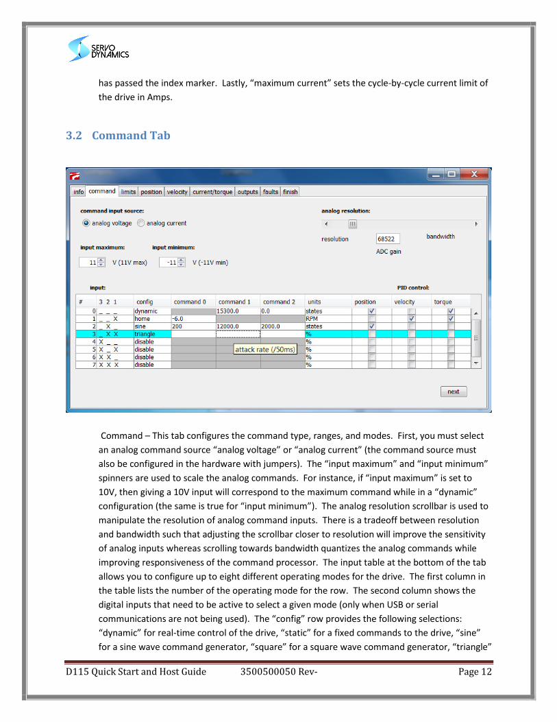
3.2 Command Tab
Command – This tab configures the command type, ranges, and modes. First, you must select
an analog command source “analog voltage” or “analog current” (the command source must
also be configured in the hardware with jumpers). The “input maximum” and “input minimum”
spinners are used to scale the analog commands. For instance, if “input maximum” is set to
10V, then giving a 10V input will correspond to the maximum command while in a “dynamic”
configuration (the same is true for “input minimum”). The analog resolution scrollbar is used to
manipulate the resolution of analog command inputs. There is a tradeoff between resolution
and bandwidth such that adjusting the scrollbar closer to resolution will improve the sensitivity
of analog inputs whereas scrolling towards bandwidth quantizes the analog commands while
improving responsiveness of the command processor. The input table at the bottom of the tab
allows you to configure up to eight different operating modes for the drive. The first column in
the table lists the number of the operating mode for the row. The second column shows the
digital inputs that need to be active to select a given mode (only when USB or serial
communications are not being used). The “config” row provides the following selections:
“dynamic” for real-time control of the drive, “static” for a fixed commands to the drive, “sine”
for a sine wave command generator, “square” for a square wave command generator, “triangle”
D115 Quick Start and Host Guide 3500500050 Rev- Page 13
for a triangle wave command generator, “home” to initiate a home find, or “disable” to disable
the drive when the mode is selected. The next three columns are labeled as “command 0”,
“command 1”, and “command 2”. These columns represent different parameters depending on
what has been selected for “config” in a given row. After making a “config” selection, moving
the cursor over any of the command cells will display a tooltip explaining what should be
entered in that command cell. At the right-most end of the table, we see columns with
checkboxes for “position”, “velocity”, and “torque”. These checkboxes enable/disable their
corresponding PID control loops. Enabling more than one PID loops will cascade the PID blocks
for finer control (where the left-most checkbox always closes the outer loop). The units
associated with the command amplitude, maximum command, or minimum command will
change depending on which of the PID blocks are selected in the row (and can be seen in the
“units” column). If none of the PID blocks are enabled, the command units default to duty cycle
percentage.
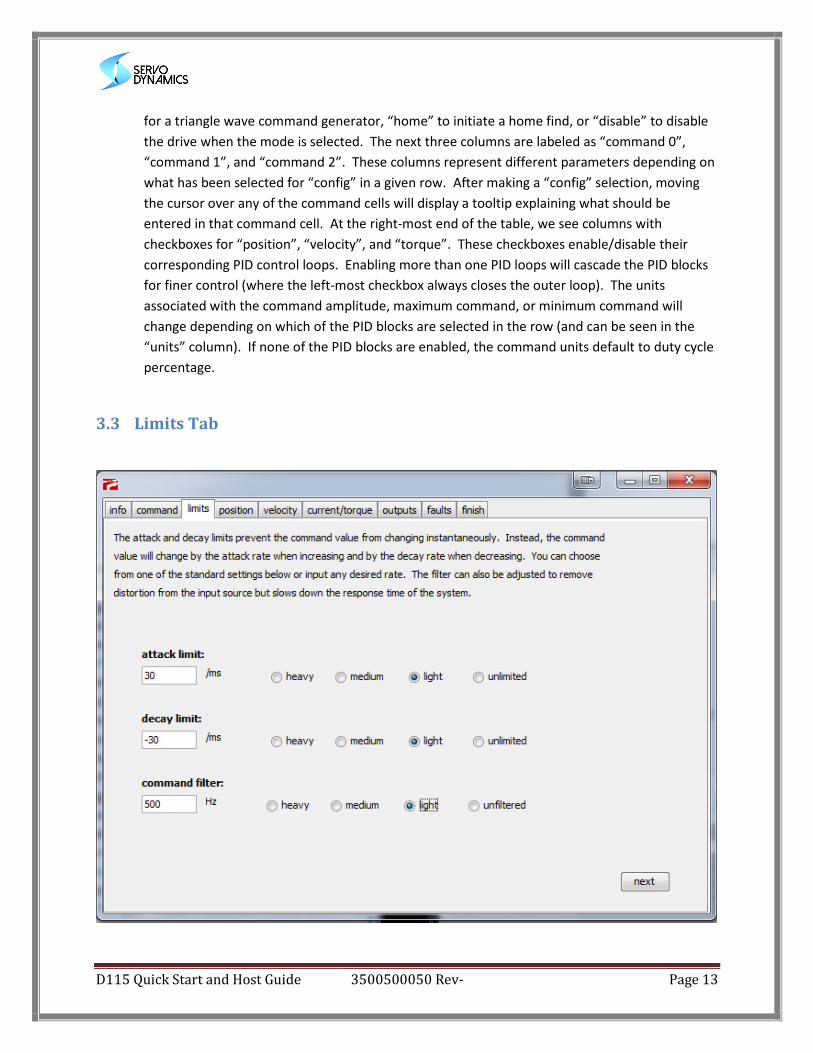
3.3 Limits Tab
D115 Quick Start and Host Guide 3500500050 Rev- Page 14
Limits – The limits tab configures command processor values for the drive. Each of these have
predefined values that can be used by selecting the “heavy”, “medium”, “light”, and
“unlimited/unfiltered” buttons. Alternatively, you can enter custom values by using the text
fields. The “attack limit” determines how much the absolute value of the magnitude of the
command can increase in one millisecond. The “decay limit” determines how much the
absolute value of the magnitude of the command can decrease in one millisecond. Lastly, the
command filter sets the cutoff frequency for the lowpass filter (where a value of 0 will bypass
the filter altogether).
3.4 PID Tabs for Position, Velocity, and Current/Torque
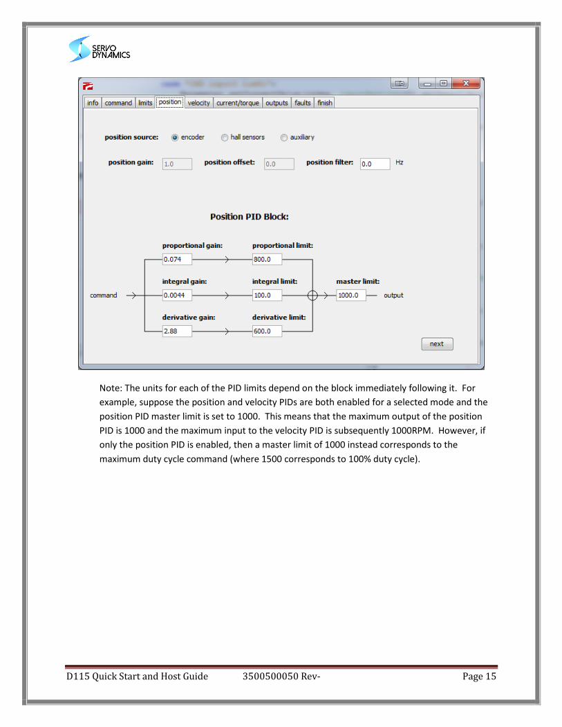
PID – The “position”, “velocity”, and “current/torque” PID tabs are used to configure gains,
limits, and feedback settings for each corresponding PID block. The “position” and “velocity”
tabs allow you to choose between “encoder”, “hall sensor”, and “auxiliary” feedback sources as
well as set a cutoff frequency for lowpass filtering applied prior to the feedback entering the PID
algorithm (where entering 0 will bypass the filter). The “current” tab only allows for filtering as
only the internal current sensors can be used as a feedback source. Floating-point values can
be entered for each of the three gains and associated limits. The proportional, integral, and
derivative terms are calculated independently before being summed and limited by the “master
limit” value. After being master limited, the output of the PID block is sent as the command to
any subsequent enabled PID blocks where the process is repeated. Tuning the PID values can be
tricky, and it is best to start with default values from a configuration file and make minor
adjustments as necessary.
D115 Quick Start and Host Guide 3500500050 Rev- Page 15
Note: The units for each of the PID limits depend on the block immediately following it. For
example, suppose the position and velocity PIDs are both enabled for a selected mode and the
position PID master limit is set to 1000. This means that the maximum output of the position
PID is 1000 and the maximum input to the velocity PID is subsequently 1000RPM. However, if
only the position PID is enabled, then a master limit of 1000 instead corresponds to the
maximum duty cycle command (where 1500 corresponds to 100% duty cycle).
D115 Quick Start and Host Guide 3500500050 Rev- Page 16
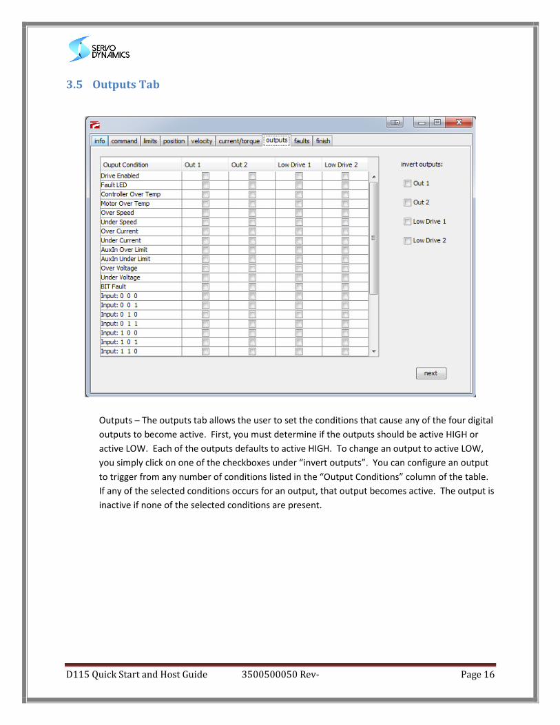
3.5 Outputs Tab
Outputs – The outputs tab allows the user to set the conditions that cause any of the four digital
outputs to become active. First, you must determine if the outputs should be active HIGH or
active LOW. Each of the outputs defaults to active HIGH. To change an output to active LOW,
you simply click on one of the checkboxes under “invert outputs”. You can configure an output
to trigger from any number of conditions listed in the “Output Conditions” column of the table.
If any of the selected conditions occurs for an output, that output becomes active. The output is
inactive if none of the selected conditions are present.
D115 Quick Start and Host Guide 3500500050 Rev- Page 17
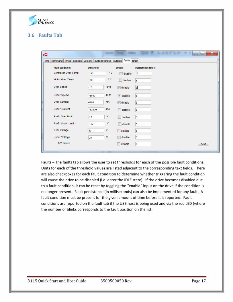
3.6 Faults Tab
Faults – The faults tab allows the user to set thresholds for each of the possible fault conditions.
Units for each of the threshold values are listed adjacent to the corresponding text fields. There
are also checkboxes for each fault condition to determine whether triggering the fault condition
will cause the drive to be disabled (i.e. enter the IDLE state). If the drive becomes disabled due
to a fault condition, it can be reset by toggling the “enable” input on the drive if the condition is
no longer present. Fault persistence (in milliseconds) can also be implemented for any fault. A
fault condition must be present for the given amount of time before it is reported. Fault
conditions are reported on the fault tab if the USB host is being used and via the red LED (where
the number of blinks corresponds to the fault position on the list.
D115 Quick Start and Host Guide 3500500050 Rev- Page 18
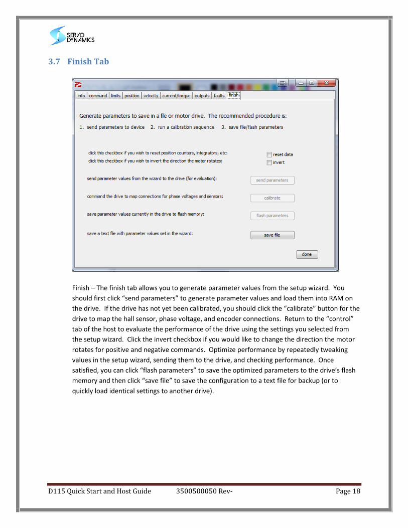
3.7 Finish Tab
Finish – The finish tab allows you to generate parameter values from the setup wizard. You
should first click “send parameters” to generate parameter values and load them into RAM on
the drive. If the drive has not yet been calibrated, you should click the “calibrate” button for the
drive to map the hall sensor, phase voltage, and encoder connections. Return to the “control”
tab of the host to evaluate the performance of the drive using the settings you selected from
the setup wizard. Click the invert checkbox if you would like to change the direction the motor
rotates for positive and negative commands. Optimize performance by repeatedly tweaking
values in the setup wizard, sending them to the drive, and checking performance. Once
satisfied, you can click “flash parameters” to save the optimized parameters to the drive’s flash
memory and then click “save file” to save the configuration to a text file for backup (or to
quickly load identical settings to another drive).