D T IC · Prepar'ed for D T IC AFWAL/FIuLA ... The test aircraft was modified at the 4950th Test...
138
4950-FTR-86-4 AD-A176 148 ADVANCED ELECTROMECHANICAL ACTUATION SYSTEM (EMS) ~ FLIGHT TEST William J. Norton, First Lieuterant, USAF Advanced Aircraft Systems Branch Aircraft and Avionics Division Directorate of Flight Test Engineering June 1986 Final Report for Period July 1985 - March 1986 Approved for public release; distribution unlimited. Prepar'ed for D T IC AFWAL/FIuLA Control Systems Development Branch JAN2 2 1987 Flight Controls DiVision Flight Dynamics Laboratory S " Air Force Wright Aeronautical Laboratory Aeronautical Systems Division Wright-Patterson AFB, Ohio 45433-6553 Sl riLE COwY 4950TH TEST WING /AERONAUTICAL SYSTEMS DIVISION AIR FORCE SYSTEMS COMMAND WRIGHT-DATIERSON AFB, OHIO 45433-6513 .-. 87 1 2 1I
-
Upload
nguyenhanh -
Category
Documents
-
view
213 -
download
0
Transcript of D T IC · Prepar'ed for D T IC AFWAL/FIuLA ... The test aircraft was modified at the 4950th Test...
4950-FTR-86-4
AD-A176 148ADVANCED ELECTROMECHANICAL ACTUATION SYSTEM (EMS)
~ FLIGHT TEST
William J. Norton, First Lieuterant, USAFAdvanced Aircraft Systems BranchAircraft and Avionics DivisionDirectorate of Flight Test Engineering
June 1986
Final Report for Period July 1985 - March 1986
Approved for public release; distribution unlimited.
Prepar'ed for D T ICAFWAL/FIuLAControl Systems Development Branch JAN2 2 1987Flight Controls DiVisionFlight Dynamics Laboratory
S " Air Force Wright Aeronautical LaboratoryAeronautical Systems DivisionWright-Patterson AFB, Ohio 45433-6553
Sl riLE COwY4950TH TEST WING
/AERONAUTICAL SYSTEMS DIVISIONAIR FORCE SYSTEMS COMMAND
WRIGHT-DATIERSON AFB, OHIO 45433-6513 .-.
87 1 2 1I
NOTICE
When Government drawings, specifications or other data are used for any purposeother than in connection with a definitely related Government operation, theUnited States Government thereby incurs no esponsibility nor any obligationwhatsoever; and the fact that the Government. may have formulated, furnished, orin any way supplied the said drawings, specifications, or other data, is not tobe regarded by implication or otherwise as in any manner licensing the holder orany other person or corporation, or conveying any rights or permission tomanufacture, use, or sell any patented invention that may in any way be relatedthereto.
This report has been reviewed and approved for publication.
ip Flght Tedt Ein~wrfn
ARK M. WALKER, -ni USAF
Do not return copies of this report unless contractual obligations or notices ona specific document require that it be returned.
*A1

ECLASSIF CA TON/OOF TIS AIGSCEO EAprvdfr ubcrees, itib in
~ PRFOMIN ORANI~ITON REPORT NUMERS) U .MONTAITOING ORGAEZTO EORURS
ttlI Ai ForceSI Wrigh Aeonutca ItaIIoratoriesARKN(.
A MEO PERFORMING ORG-ANI ZA TION REPOFFIC SYMBOL(S 5..ASO MONITORING ORGANIZATION RPR USRS
Wright-Pattersoni FoO 54361 rigtcteWrighn Aernatia OHbora3o-65s3
(3a NAME OF PEFUORINGSORGNSO IZAIO fb. OFFICE SYMBOL 'I. NRA URME r OF INSTQRUMN T O tRG NrIZA ICrON NMIlIORGANIAT IONappticatle)
6, ADDRESS (City. State and ZIP Code) 1b. SOURCES OFty F tt anOdN N o de)
NAM O FUDIG/PONORNG8b.OFICESYBO 9.PEL UEM LN ISTUENT NO NO.NTVCFON NOBI
11 ADDRLES tnctiY Staeur dIty C~aulctonAd vace El. ectRo- O1 F FNIGNS
12ORA PERSONA ACTIOS TAnclassified
ELEEN SUPLMNTR NOTATOOo
61101Ft and4 2403 0
I U 7 IF LE HU !Icld SUBrit C~sst ca n Adaned ectro-ietaio 6221OF 0)SytI1,Zm~.,lt..~i
TeAvneElcrmechanical Actuation System (EMAS)Lflight testipoetscesul
12PROAL-Eeti Airplane (AA)cncept.sAnieletidcutrwsintle nmdfe
maxt imuim effNortrolldgaenytmrls rdatpltrls ielpadtitst.TP pOint wEPRe also pefoMEd COVtE was verifEd tha REPR[Y.MAS. pefrance was simiarN t
the normal hydraulic actuator.tRoesultsincalude lessionso icat oiainItnra syte chrcersis maintnanc facors and compatiuility, with otherfflr rntt ytesta mayplanfluAnc, future intlations.~jTros,- perfomonc
19IU.I141U)NA~iAIIYO ABSTRACT 21ntnu AoTRn SECvRITY CLASSIFICATIONfybyblcnunb r . - D
demonstra It edN~i EDr the SAM st ASRTL tiC UE RS elenrcal actuai o fi a rmredih oto
litur Williamge.Nonrton ytmdmig Aircraft30rol pefomacethests included
D es FORM t 1473 e al3 APRored I t wasN OFife tha JAN perfOrOLEE.ancl as sified t
:en1w 1;4 Ik)TiN/ VALAI I Y F BSRAT ASTAC SC1RIY LASE FC A~Ty LSI FIAINOFTISPG

S UTiMAR Y
The purpose of this test was to demonstrate in flight for the first time thefeasibility of powering a primary flight control surface with anelectromechanical actuator (EMA) in place of the standard hydromechanicalactuation system. An advanced development model model EMA drove the left aileronon a specially modified C-141A aircraft and was to duplicate the functions of thestandard hydromechanical unit. Lockheed-Georgia Co. (GeLac) was the primecontractor with Sundstrand Corp. as the subcontractor.
The Electromechanical Actuation System (EMAS) consisted of a dual motor electricactuator mounted in the aileron actuator bay, and associated power supply andlogic electronics constituting the dual channel Controller Electronics (CE) unitlocated in the cargo bay of the aircraft. Both channels were as physically andelectrically isolated as possible. The system obtained its power from twoseparate electric buses aboard the aircraft. A single EMAS channel could powerthe actuator, though with reduced capability. The EMAS incorporates extensiveII built in test and fault detection circuitry that can automatically shut down afaulty channel(s). Operatir.g procedures of the EMAS were identical to that ofthe normal system.
The test aircraft was modified at the 4950th Test Wing to accommodate the EMAS,including electrical and hydraulic changes necessitated principally by therequirement to maintain electrical power to the system or to select backup taboperation of the aileron under all conceivable emergency situations. EMAS andaircraft instrumentation permitted the monitoring of system performance, aircraftresponse, and a one-for-one comparison with t~he unmodified right aileron controlsystem.
The testing included ground trials to ensure readiness for flight and a groundvibration test (GVT) to determine the dynamic frequency response of the systemand to verify unchanged damping characteristic. The flight test began with adamping investigation to clear the test envelope. Subsequent trials consisted ofroll perfermance and degraded systems tests.
Ground and flight tests showed that the damping of the modified system wasunchanged from the baseline configuration. A system modification was required toeliminate a system instability experienced during the GVT. The instability wascharacterized by a neutrally-damped aileron oscillation which was attributed toan aileron control system characteristic.
During the switching from ground to aircraft power sources, a single EMAS channeloften shut down. This may indicate a sensitivity to momentary losses of power.Also in ground trials, a channel repeatedly shut down during maximum commandaileron control cycles because of the drifting of electrically set actuatortravel limits. This drifting may have been caused by large ambient temperaturevariations or travel limit overshoot in the absence of airloads, and isundesirable. Rigging adjustment eliminated the shut downs.
The normal hydraulic actuator and the EMAS produced sudden aileron movementduring initial Dower up when the surface deflection was not in the proper

position relative to Lihe yoke. This created a potential hazard to maintenancepersonnel. The nature of the EMAS may provide the opportunity to eliminate thisground hazard. Higher backdrive forces for the inert EMA as compared with theinert hydraulic actuator increased the forces required to move the unpoweredaileron and presented an increased maintenance task. It was possible to positionthe aileron by turning the ball nut that moved the EMAS actuator ram. This wasadvantageous to maintenance personnel. When temperature dropped to approximatelybelow freezing, manual actuator movement was not possible.
Except for a few discrepancies, the flight test demonstrated that the EMASduplicated the hydromechanical aileron actuator performance, within themeasurement capability of the test instrumentation. Because of off-the-shelfcomponent inadequacies, the EMAS could not meet the normal travel limits of theC-141 aileron, falling short by one degree at each end-of-travel. The EMASend-of-travel slow-down feature resulted in the aileron requiring an average of0.3 seconds more to reach the travel limit than the unmodified system. These twodiscrepancies resulted in different roll rates during maximum command rolls tothe left and right and inability to match limited baseline performance data.These discrepancies were not detectable by the pilots.
Single channel operations were similar to full system operation and no aileronmovement was experienced during channel deacti'vation and activation. Because ofthe higher forces required to move the aileron against an inert EMA, theunpowered left aileron floated to a smaller deflection than the unpoweredhydraulically-actuated right surface, although backup tab operable performancewas not reduced from baseline.
A maximum current draw by the EMAS of 12.5 amps was observed, well within the 50amp e,,cess capacity of the electrical buses. The EMAS was observed to be moresensitive to inputs than the hydraulic actuator, making more and larger fineadjustments during autopilot trim maneuvers and reproducing small control systemaberrations. The EMAS responded to autopilot inputs without difficulty. Nomotor or actiator bay temperature gradients were observed at any time duringground and flight operations
85% of the planned flight test was successfully completed. The testing wasterminated on the sixth sortie because of an EMAS failure. One channelrepeatedly disengaged in flight because of a current imbalance between themotors, and the aileron exceeding the normal displacement limits. Duringsubsequent ground testing, the actuator exhibited similar faults and alsoexecuted uncommanded deflections at higher than normal maximum travel rate. Thelast of these uncommanded excursions passed the normal travel and electricallimits, and resulted in the mechanical stops being damaged (not designed towithstand such a load). The cause of these faults could not be determined andcorrected in time to complete the flight test within schedule constraints.
The EMAS flight test demonstrated the feasibility of powering a primary flightcontrol surface with an electromechanical actuator and tailoring it to specificpcrformance requirements. It showed that the installation of such a system intoa pre-existing airframe can be effected without structural modification and withonly minor electrical changes.
ii

PREFACE
This flight test constituted the first use of a electromechanical actuator for aprimary flight control surface, and represented a major step toward therealization of the all-electric airplane concept.
This flight test was performed under project number 240306TP. The test was part
cf a program sponsored by the Air Force Wright Aeronautical Laboratories (AFWAL)in response to an unsolicited proposal from the Lockheed-Georgia Co., with theSundstrand Corp. acting as the subcontractor. The test aircraft, NC-141A, serialnumber 61-2775, was modified by the 4950th Test Wing and flown for 12.9 hours in6 sorties, all of which were launched and recovered at Wright-Patterson AFB,Ohio.
The author wishes to acknowledge the contributions of the aircrew; Project PilotCapt Samuel Kinard, Test Pilot Capt Larry Schultz, Pilot Maj Wayne Stanberry, andFlight Engineers MSgt Peter Van Havermat, TSgt Kenneth Hauprich, MSgt JosephKeck, SSgt Duane Smith, and CMSgt Donald Turner. Also, d special note of thanksfor test planning and modification assi.tance is extended to Flight Engineer TSgtStephen Broander. Thanks are extended to the instrumentation personnel, Mr BillBenedict and SSgt David Jankowski, and for' da.a reduction in the person of MrHobart Drum. A special thanks to Ms Lydia Flaugher and all the fine engineers atthe Special Programs Division of the Directorate of Aircraft Modification. Anote is due Mr Faus-tino Zapata for his advice Onl- structural drIdlySis. Thanks tothe contractor personnel who spent many long days on the project; Ken Thompson,Ralph Alden, and Mark Bailey of Lockheed-Georgia, Brent Kaiser, Fenton Reese, andGraham Bradbury of Sundstrand. Lastly, thanks to the Program Manager, Capt LarryHunter, who suffered through it all from the beginning. Accolades also to allthe other unnamed contributors in the Program Office, Test Wing, and contractorsorganizations.
iii

TABLE OF CONIENTS
Title Page
INTRODUCTION ............... ........................ ... 1-1
Background ............... .................... .. 1-1
Ojectives ............. ........................ ... 1-1
TEST ITEM AND INSTALLATION .......... ................. .. 2-1
EMAV Technical Description ........................... 2-1
Aircraft Modification ......... .................. ... 2-3
INSTRUMENTATION AND TEST EQUIPMENT ....... ............. .. 3-1
TEST PROCEDURES ................ ....................... 4-1
Ground Tests ..................... .4-1
Rigging ............. ....................... ... 4-1EMC/EMI ................. ....................... 4-1GVT ...................................... 4-1
Flight Tests . . . . . . . . . . . . . . . . . . . . . . 4-2
Airworthiness Tests .......... ................. .. 4-2Performance Tests ............................... 4-2
DATA REDUCTION AND ANALYSIS ....... ................. ... 5-1
TEST RESULTS AND DISCUSSION ......... ................. ... 6-1
Aircraft Modification ......... .................. ... 6-1
General Characteristics ......... ................. ... 6-1
Maintenance Factors .............. .................. 6-2
EMC/EMI. ............... ........................ .. 6-2
GVT .............. ........................... ... 6-2
iv

TABLE OF CONTENTS (cont.)
Title Page
Flight Test . . . . . . . . . . . . . . . . . . . . . . 6-3
Current Draw . ................... 6-3Thermal Behavior .................... 6-3Fully Powered Roll ?erforniance ........... 6-3Deflection Sensitivity ...... ....... ............... 6-4Degraded System Performance ....... ............. .. 6-5Tab Operable Roll Performance ..... .......... ... 6-5Aileron Damping ....... ..... ....................... 6-5Autopilot Interaction .. ..... ....... ................ 6-6Takeoff and Landing ....... ... ................. .. 6-6System Failure ...... ......... .................... 6-6Structural Design ....... ... .................. ... 6-7
CONCLUSIONS AND RECOMMENDATIONS ........ ............... ... 7-i
LIST OF ABBREVIATIONS .......................... 8-1
REFERENCES ....... ..... ... ......................... ... 9-i
APPENDIX A TEST DATA .......... .................. ... A-1
APPENDIX B BASELINE DATA ....... ................... ... B-1
APPENDIX C ADDITIONAL TEST DATA ...... ............. ... C-1
APPENDIX D ACIUATOR TECHNICAL DATA ..... .......... ... D-1
DISiRIBUTION LIST
V

LIST OF ILLUSTRATIONS
Figure Title Page
2-1 Electromechanical Actuator (EMA). ...... ..... ...... 2-4
2-2 EMAS Controller Electronics. ... ....... ............ 2-5
2-3 EMAS Block Diagram. .... ....... ..... ....... . ..... 2-6
2-4 C-141 Aileron Control System ... ....... ............ 2-7
2-5 Aileron Control System and EMAS Interface. .......... 2-8
2-6 C-141 Baseline/EMAS Aileron Schedule. .. .. .......... 2-9
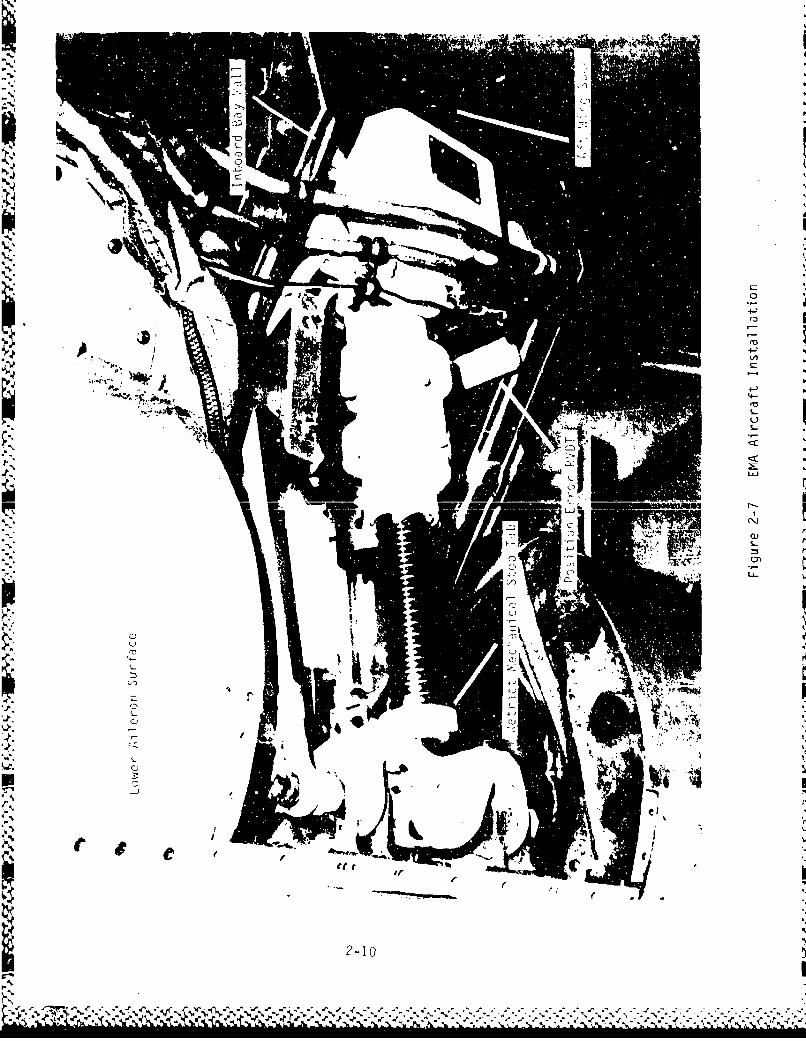
2-7 EMA Aircraft Installation ...... ..... ....... ...... 2-10
2-8 EMAS Modification Profile. ..... ..... ....... ...... 2-11
2-9 Hydraulic System Modification. ..... ..... .......... 2-12
6-1 Baseline/EMAS Roll Comparison. ..... . .... .......... 6-9
6-2 EMA Mechanical Stop Damage ..... ....... ..... . ..... 6-12
I PEDXA-1 Ground Control Cycle. .... ....... ..... ............ A-i
A-2 Maximum Deflection Roll .. .... ....... ..... ........ A-6
A-3 Control System Response .... ..... ....... ........ A-26
A-4 Autopilot Roll ....... . .... ....... . .... .......... A-30
A-5 Maximum Deflection Degraded Roll. ...... ..... . ..... A-34
A-6 Maximum Deflection Tab Roll. ..... . ...... .......... A-42
A-7 Tab Operable Roll-Off .. .... ..... ....... .......... A-50
A-8 Trim Shot .. .. ....... . ...... ..... ....... ........ A-60
A-9 Aileron Pulse. ..... ..... ....... ..... ............ A-62
vi

LIST OF ILLUSTRATIOS(cn.
Figure Title Page
APPENDIX B
81 Maximum Deflection Roll ...... ............ ........B-1
B-2 Tab Select Trim Change..... ............ ...........-3
B-3 Tab De-Select Trim Change.... ............ ........B-4
8-4 Bank-To-Bank Tab Roll ...... ............ ...........- 5
APPENDIX C
C-1 Wing Response........ ..... .. . .. .. .. .. .. . .....
vii

LIST OF IABLES
Table Title Fage
3-1 EMAS Aircraft Instrumentation ... ........... .... 3-3
4-1 Flight Test Matrix ... ....................... ... 4-4
6-1 Maximum Deflection Rolls ... ... ............. ... 6-8
6-2 Degraded System Roll Performance ... ..... ........ 6-10
6-3 Tab Operable Roll Performance 6............-1
viii

INTRODUCT ION
1. Background
a. The Advanced Electromechanical Actuation System (EMAS) flight testprogram demonstrated for the first time the performance of an electromechanicalactuator (EMA) while powering a primary flight control surface on a C-141Aaircraft. The EMA had been designed to replace the existing hydromechanicalactuatur system with a power-by-wire system. When combined with its naturaladjunct, the fly-by-wire technology, this will be a critical step towardrealization of the all-electric airplane (AEA) concept. The principal benefitsof EMAS and an all-electric airplane are anticipated to be reduced componentweight, greater reliability, improved maintainability, reduced logistics, betterredundancy management, increased safety, and a significant reduction in lifecycle costs. Among factors that influenced the selection of the C-141 aircraftas the testbed airframe was that there is sufficient space within the C-141actuator bay to accommodate the EMA unit. The C-141 has a backup tab operablecontrol system for aileron actuation which enhanced flight safety in the event ofa total EMAS failure. Operational incidents have demonstrated that the aircraftcan be safely recovered and landed with an aileron hardover failure. And, thetest aircraft was readily available.
b. NC-141A, serial number 61-2775, was modified by the 4950th Test Wing forthe EMAS flight test between July and September 1935 at Wrinht-Patterson ,A, FB,Ohio. Testing included a ground phase to ensure flight safety and systempreparedness followed by the flight phase. The flight phase consisted of anairworthiness portion followed by roil performance tests. The aircraft was flownfor 12.9 hours during six sorties in February 1986. All phases of the test wereconducted at Wright-Patterson AF8. The 49.,Oth Test Wing project number was240306TP.
2. Objectives
This project was to demonstrate, in-flight, the feasibility of powering andcontrolling a primary flight control surface witi a dual channel redundantelectromechanical actuator, document the performance of the actuator, and confirmthat the EMAS installation could be implemented safely and efficiently,consistent with the performance requirements of the control surface.
LI
1-1 (1-2 blank)
* I,.

TEST ITEM AND INSTALLATION
"1. EMAS Technical Description
a. The advanced development model EMA (see Figure 2-1) weighed 65 pounds(Ibs), six lbs heavier than the conventional hydraulic power control unit (PCU).This difference was caused primarily by an assembly that interfaces the singleEMA ram with the existing dual ram connection, and the use of commerciallyavailable components and machined rather than cast hardware. The contractorpredicted that a production version would weigh less than the hydromechanicalunit. The EMAS dimensions are comparable to those of the PCU, fitting theactuator bay without structural modification. EMAS was designed to perform allof the functions of the original hydraulic actuator without altering theperformance or stability and control of the aircraft. A listing of detailed EMAStechnical data is given in Appendix D. The EMAS was a redundant dual channelunit (channel A and channel B) employing two electric motors, a gear train, and alinear ball screw assembly. A single motor is capable of effectively moving theaileron. The controller electronics (CE) provided the power to the EMA motorsand processed all EMA signals, transmitted via a wire bundle between itself andthe aileron actuator bay. The CE is contained in a double-bay Johnson rack (seeFigure 2-2); however, a production unit would be reduced to a small box.
b. The CE required 115 VAC-3 phase and 28 VDC power. AC power was obtainedfrom the aircraft number two main and number two essential buses, powering the Aand B channels, respectively, and converted at the EMAS rack to direct current(up to 270 VDC) to power the actuator and other powar for electronicrequirements. The 28 VDC originated at the pilot overhead left aileron switchingpanel and serves to turn on the EMA channels when the switches are in the NORMALposition by holding closed a relay between the CE power supply and the actuator.These switches (one for each hydraulic or EMAS channel) have NORMAL (powered),OFF (unpowered), and TAB (tab operable) settings and served the same functionswith the EMAS as they do for the hydraulic PCU.
c. Aileron deflection commands were transmitted to the actuator by way of thenormal aircraft mechanical control system consisting of cables, pulleys,
bellcranks, pushrods, and linkages (see Figure 2-3 and 2-4). The feedbacklinkage normally used to position the hydraulic actuator control valve displacedtwo input or position error Rotary Variable Differential Transformers (RVDT), onefor each channel, through the override spring and input arm (see Figure 2-1).When displaced, the RVDT produced an electronic command interpreted by the CE.The CE supplied a corresponding amount of voltage necessary to produce therequired motor te.ýque (see Figure 2-5). The power is supplied until the surfacereaches the commanded position which mechanically returns the RVDTs to the nullposition, thus stopping the power for motor torque.
d. Prior to the test, it was understood that deficiencies in off-the-shelfcomponents resulted in the EMA being unable to meet expected maximum ailerontravel limits. In order to provide a sufficient aileron over-travel safetymargin above the normal C-141 aileron travel limits of 25 degrees (deg) trailingedge up and 15 deg down, travel was limited to 24 and 14 deg with the normaltravel schedule maintained up to these points (see Figure 2-6). System damage
2-1

was prevented by electronically restricting deflections from exceeding thiscontrol surface travel limit by more than one degree, and with actuator commandreduced to 10-15 percent of maximum deflection rate beginning at approximatelytwo degrees from the limits. This slow-down feature also worked in reverse,reducing aileron motion as it came off of the limit. System disengagementoccurred when the actuator reached the electrical stops. Mechanical stops are inthe form of two pair of metal tabs that butt at maximum extension or retractdeflection of 26 and 16 deg aileron travel. Additional aileron position RVDTsprovided information for the over-travel limit function.
e. Both EMA motors operated simultaneously along a single drive screw,producing equal loads, unless either had been selected OFF or had beenautomatically shut down as a result of a fault sensed by the CE. One motor wassufficient to perform actuator functions, though with degraded roll rate becauseof limited load, deflection travel, and deflection rate capability. Motor torquewas transmitted via the gear train and linear ball screw to produce surfacedeflection.
f. The EMAS incorporated fault detection and response functions for systemsafety. The CE shut down the affected channel when a thermal switch incorporatedinto the motor windings closed at 400 deg Fahrenheit (F) or when the motor drivepower transistors' heat sink exceeded 250 deg F. The two EMA channels weremonitored for force fight which would be reflected in a current difference. Anexcessive difference would result in channel A being disabled as an arbitraryselection to eliminate the imbalance. If channel B created the fault thatproduced the imbalance, that fault would then be detected and B shut down. Inanother fault detection, the affectea channel is disengaged if a vultage of 200VDC is supplied for two seconds or more (indication of a runaway motor) sinceonly one second was required for the actuator to stro' ý from full retract to fullextend, or vice versa. A disengagement of both EMA (or PCU) channels wouldresult in the aileron floating to approximately 5-8 deg trailing edge up
deflectioi, a freestream or zero hinge moment condition, prior to engagement ofthe tab operable system. 360 lbs of force was required to backdrive the screwagainst inert motors (both channels disengaged), equating to approximately 60-70lbs of force at the aileron trailing edge. Other fault modes include componentfailure detection such as RVDT nd motor resolver. Many of these faults wereidentified by indicators in the ront panel of the CE. If a fault resulted inthe channel being disengaged, only a power recycle (pilot switches) wouldreengage the unit, provided the fault was not still present. Each motor and CEchannel was physically and electrically isolateo to the greatest extent possibleto ensure that a fault disabling one channel did not affect the other. Thefailure of one of the aircraft electrical sources or EMAS internal powersupplies, such as a voltage surge to 325 VDC or sudden orop to 240 VDC, wouldresult in the loss of the affected channel.
g. The EMA had undergone extensive laboratory testing and computer simulationand was certified as airworthy. As with the hydraulic PCU, a failure of eitherEMAS channel was indicated by a flashing MASTER CAUTION light and a failure lightadjacent to the affected channel on the aileron power control switching panel.Power to the EMA was ccntrolled by the aileron power control switches in thecockpit. Power to EMAS was controlled by two circuit breakers, one for eachchannel. In the event of a dual motor failure, EMA shut down, or a totalaircraft electrical system failure the aileron could be operated by tab.
2-2

h. The EMAS had redundant fault monitoring for an aileron hardover failure.Such a failure would require a fault in both motors allowing runaway motors. Asingle motor runaway would be opposed by the second motor creating a force fight.This force fight would be detected as a current difference and result in an EMAshutdown. Travel limits and high motor drive voltage for an excessive period oftime would also result ir a shutdown prior to the aileron reaching the electri:alor mechanical travel limits. Therefore, multiple faults had to occursimultaneously for a hardover to result. In the event of a hardover, a singlemotor was sufficient to return the aileron from the hardover position or bedriven back by aerodynamic forces. Depowering EMAS and reverting to tab operablewas the standard emergency procedure. Depowering would result in the aileronfloating to a zero hinge moment condition.
2. Aircraft Modification
a. The EMA was designed as a "drop-in" replacement for the existing C-141aileron actuator, requiring no structural modification to the aircraft (seeFigure 2-7). It was compdtible with the manual tab operable aileron system foremergency backup, and required no change to the autopilot, roll trim, or rollartificial feel systems. It utilized the existing flight control systems andmonitoring functions and required no change to normal operating procedures. Amodification profile is provided in Figure 2-8.
b. Sections of the unused PCU hydraulic lines in the actuator bay wereremoved and capped to provide room for the EMA. In order to permit backup taboperation of the left aileron in the event of total electrical system failure,the tab operable solenoid valve was connected to the Number 2 hydraulic system inplace of the Number 3 system (see Figure 2-9). This valve ports hydraulic fluidto a tab operate cylinder, unlocking the tab lockout actuator and moving a tabinput bellcrank from an over-center position to permit control commands to deploythe tab and assist in moving the aileron with aerodynamic forces. The Number 3hydraulic system is electrically dependent whereas the Number 2 system is enginedriven and would continuously provide pressure to the solenoid in the event of anelectrical failure. In addition, a relay between the emergency DC bus and theisolated DC bus was installed to ensure an uninterrupted source for the 28 VDCpower used to hold open the solenoid valve, thus ensuring that this functioncould be performed in the event of a total electrical system failure or if thecrew should need to shut down the isolated bus as part of the electrical firechecklist procedure. A calibrated outside air temperature probe was added to theaircraft to provide a precise source for this parameter.
c. The EMA CE was placed in a double-bay "Johnson" rack. Electrical wirebundles from this rack and instrumentation wiring to the aileron actuator baysexited the pressurized cargo compartment through the life raft compartmentinspection window apertures which were modified to provide a positive pressureseal. Life rafts were removed as a result Gf this modification.
2-3
-2 -V-

Ln
4-)U
C.,
L/)4-)~
LLIJ
L)j
2-4
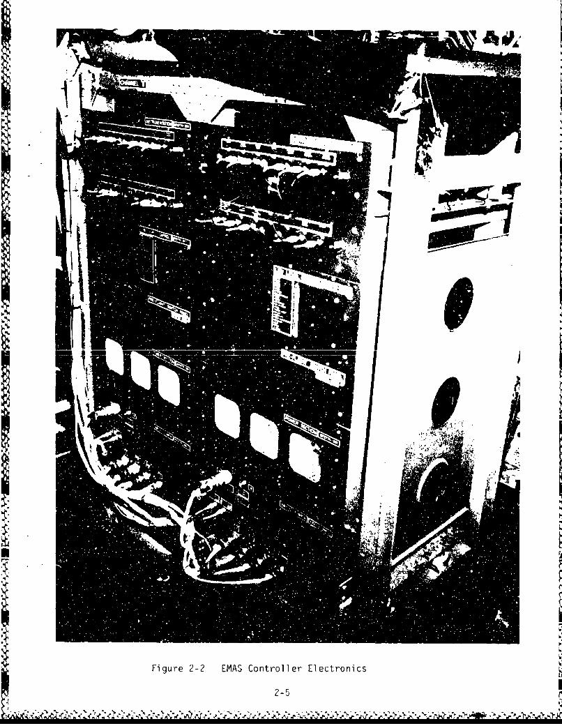
Figure 2-2 EMAS Controller Electronics
2-5 I

00
0 0
z %f
1I 0
Li -
0 I
VI 0
UA-
U. E ...
A4 coz 4A2-6

Cc
d coI.~V JA4 ~ .
qt LL C u
5-W . LC CO r-
4J 4A , 10
060
M, W Ln %a Cý 0 %
-0~L 44j 0
-- C~ 0 ,8
2-7.

TO R.H. AILERON(HYDROMECHANICAL) CONTROL
AUTO -PILOT SERVO
COCKPIT •FEEL BUNGEECONTROLS I
AILERON /"tRIM ACTUATOR
"NORKMAL F %d 1T ION)1`4
SHEAR JOINT "TAB OPERABLE" POSITION
TO TAB DRIVELINKAGE
- INPUT OVERRIDE BUNGEE
POSITION ERROR RVDT ACTUATOR WHICH POSITIONS ARM FROM
ON-CENTER (NORMAL) POSITION TO "TAB -
AILERON POSITION RVDT OPERABLE*POSlTION IS POWERED BY THENO. 2 HYD. SYS. ON L.H. WING AND BY
EMA THE NO. 3 (EMERG) SYS. ON R.H. W;ING
Figure 2-5 Aileron Control System and EMAS Interface
2-8

Figu re 2-6 C-141 Baseline/EMAS Aileron Schedule
EMASTrailing Edge (T. E.) Down Baseline
EMAS
T.E. Up
20
04
J
1'0~
o l
15
0
5 10 15
Aileron PositionT. E. Down - Deg
2-9
• •---4mm@'lmm.='m~m• -•'I .-'Aa AA MOL if &.Lv-'k•.amF•.U % M ,• rv- j, "-=. • - .- aft- ,-- ...... bM- bk. b,, A ,ý bL A % A ,b r 6 . .. ... r&-
2-L
- II
2-10

C41
EF
.0 a 0 0 a)4J. L
0. i. ~ IAaS U -
iv CN 0)f 4.L. 0 e ) .
4-)U
0 'o
CCA
r_4S
UJ
2-11

0~~~ z -w(. f- " , M M 4
.0z z 0J
00
A UJ
ua,
z z zz Z
0 L
2-12

INSTRUMENTATION AND TEST EQUIPMENT
1. The test EMA unit was instrumented by the contractor for performanceevaluation. 19 parameters were selected. The asterisk indicates parametersdisplayed real-time aboard the test aircraft.
a. Power supply bridge voltage, one for each channel. *
b. Power supply bridge current, one for each channel. *
c. Motor temperature, one for each motor. *
d. Actuator output position, one for each channel. *
e. Actuator position error, one for each channel. *
f. Current imbalance. *
g. Voltage command, one for each channel. *
h. Controller ON indicator, one for each channel.
i. Actuator brake switch, one for each motor.
j. Motor speed, one for each channel. *
2. The test aircraft was instrumented to permit an evaluation of aircraftresponse to the EMA inputs. A total of 24 aircraft parameters complemented theEMAS parameters. A summary of the principal instrumentation used in the analysisof test results are provided in Table 3-1. The aircraft parameters are listedbelow. Asterisks indicate parameters displayed real-time aboard the testaircraft, although usually for A channel only.
a. Center of gravity vertical acceleration. *
b. Left and right wing vertical acceleration. *
c. Essential number 2 and main number 2 bus voltage.
d. Essential number 2 and main number 2 bus current.
e. Left and right aileron position. *
f. Rudder position (35 deg travel limit either side).
g. Wing center section aileron control quadrant position.
h. EMAS and PCU input quadrant position.
i. Time (slow and modulated code). *
3-1
' ! _4I

j. Indicated airspeed.
k. Indicated pressure altitude.
1. Roll rate.
m. Yaw rate.
o. Bank angle.
p. Left and right aileron actuator bay temperature. *
q. Outside air temperature.
r. Autopilot aileron position command.
s. Event marker.
3. Primary test equipment included a magnetic tape recorder, stripchartrecorders, D/Pad Three pulse code modulation (PCM) monitor, time code generator,digfial temperature displays, and all supporting equipment.
4. The aileron position potentiometers had a relatively poor accuracy for theparameter measured. Although acceptable, this accuracy did not permit as fine acomparison of aileron positions relative to each other that would otherwise havebeen desirable. The relative low accuracy was the result of the small size ofthe instrument, dictated by the confined space available for mounting within theaalctuator . ... * r.* .r i alsou n"I• , uuces ani errur IiILU tLIS I drdIIleLer.
5. Wing accelerometers were mounted on brackets which were in turn mounted tothe rotation axis of the power control assembly input crank. This placed theinstruments within two inches of the inboard wall of the actuator bays. Duringthe initial second of dynamic maneuvers, the mounting bracket vibrated at highfrequency, as seen in the wing accelerometer response. This did not impact datareduction.
6. The autopilot command parameter is an autopilot computer syncro signal whichis proportional to that produced by the aileron position transmitter. Therelationship is:
A/P Command (in volts) = 11.8 x sin (2.06 x ail. def. (in deg))
3-2

S- -
I.. (J'U uI •
C4-) CL
Mn <
00 (JQ L. co U~ 0u-~ 0
,1o to OL, to U .4.) =a C 0.6a4E
0 4 .1i toCM 0) 0) M0= 0)
Sc- E s- E E -cmCL (.OU 0. 06
,.- 1 ,-. . ,-.' )',.,,-"-~ ~~ -,-cco • ;
433
a fo cr or' o
+j10 4-P 4J ) 0 4) 4-3 4-
-- -A - - -A' ->
w 43 (4 a 4) 0) Ut-
CD C
Q- 44C3D Ut43 c C) `- 0.D -- LA c04ý
0) C- CA w to-_ C' C7 0 c0 40 LO V e'ma 004wq
Luf cu C).oS
dr CD 01 CIC
C.0 433
0 j 01 fl a) C 4-3 -4C) e/5CL -j 43 4 Cg v 20- 4 34
I2r 4 -4 4-)C a 4- 'U0 4-J 4-43CA 4.. 14 (L) Q) to =- m U S
0 0 (V 41S3o I-. *a L- 0) 0)
a_ L. W- 4c4 1 a
-4 Im 0 /c S- -'4-
Ci 0 5- 5
L- - - - a -
m- (3D. "ankD

TEST PROCEDURES
1. Ground Tests
a. Rigging
The right aileron was checked for proper rigging prior to the flight test. Theleft aileron was rigged by moving the aileron to the normal travel limits,trailing edge up and trailing edge down, and adjusting the electronics to commanda stop. This operation was performed for each channel separately. The sameoperation was performed for the electrical stops, ensuring that the channels shutdown in this position. The mechanical stops were set by manually adjusting thescrew end fittings which incorporate one half of the tab pair (see Figure 2-7).The aileron was moved by manually rotating the actuator ball nut and using aninclinometer for precise measurement of the surface deflection.
b. EMC/EMI
Immediately after modification, a system checkout was performed to ensure thatthe EMAS and the EMAS-to-aircraft interface were functioning properly. Anelectromagnetic compatibility/electromagnetic interference (EMC/EMI) test wasperformed on the modified aircraft prior to the first flight to locate any mutualinterference problems between the EMAS and the aircraft. This test consisted ofoperating all aircraft systems in their various modes with the EMAS functioning.
c. Ground Vibration Test (GVT)
(1) A dynamic ground vibration test was performed by GeLac to reveal thedynamic frequency response characteristics of the control surfaces, systemdamping, and tendencies to couple with aircraft structural modes. This data wasused to ensure that the structural damping margins had not changed appreciably.The EMAS had been designed to the same dynamic characteristics as the originalhydraulic actuator. The C-141 aileron is statically and dynamically stable withthe critical flutter parameters being tip weight and actuator stiffness. Ifeither parameter were not present, the damping would still be sufficient withinthe aircraft normal operating envelope. Laboratory studies had shown that thestiffness or spring rate of the EMA was identical to the hydraulic unit. Allelse remaining unchanged, the structural damping of the modrified aircraft wasexpected to be the same as that of the baseline aircraft. The baseline aircrafthas a flutter margin more than 20% above the normal operating limitations of theC-141A, and well above the military specification (MILSPEC) requirements.
(2) The EMAS GVT consisted of three parts:
(a) Shakers were placed so as to induce excitation at the bottom ofthe ailerons near the trailin5 edges. Data was recorded during symmetric andantisymmetric excitations with the EMAS unpowered, fully powered, and with only asingle channel powered. The hydromechanical PCU was both powered (singleelectrically driven channel) and unpowered. Most of the data was obtained withthe surfaces tested individually. Frequency sweeps were made from 2 to 40 Hertz(Hz) with accelerometers placed on top of each aileron aft of the actuator and
4-1
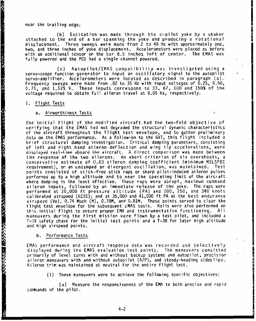
near the trailing edge.
(b) Excitation was made through the cpilot yoke by a shakerattached to the end of a bar spanning the yoke and producing a rotationaldisplacement. Three sweeps were made from 2 to 40 Hz with approximately one,two, and three inches of yoke displacement. Accelerometers were placed as beforewith an additional sensor on the bar 8.5 inches left of center. The EMAS wasfully powered and the PCU had a single channel powered.
(c) Autopilot/EMAS compatibility was investigated using aservo-scope function generator to input an oscillatory signal to the autopilotservo-amplifier. Accelerometers were located as described in paragraph (a).Frequency sweeps were made from .02 to 35 Hz with input voltages of 0.25, 0.50,0.75, and 1.125 V. These inputs correspond to 33, 67, 100 and 150% of thevoltage required to obtain full aileron travel at 0.05 Hz, respectively.
2. Flight Tests
a. Airworthiness Tests
The initial flight of the modified aircraft had the two-fold objective ofverifying that the EMAS had not degraded the structural dynamic characteristicsof the aircraft throughout the flight test envelope, and to gather preliminarydata on the EMAS performance. As a follow-on to the GVT, this flight included abrief structural damping investigation. Critical damping parameters, consistingof left and right hand aileron deflection and wing tip accelerations, weredisplayed real-time aboard the aircraft. A direct comparison was made betweenthe response of the two ailerons. An abort criterion of six overshoots, aconservative estimate of 0.03 aileron damping coefficient (minimum MILSPECrequirement), or an undamped or divergent oscillation, was maintained. Testpoints consisted of stick-free stick raps or sharp pilot-induced aileron pulsesperformed up to a high altitude and to near the operating limit of the aircraftwhere damping is the least effective. These raps were abrupt, maximum commandaileron inputs, followed by an immediate release of the yoke. The raps wereperformed at 20,000 ft pressure altitude (PA) and 200, 250, and 340 knotscalibrated airspeed (KCAS); and at 35,000 and 41,000 ft PA at the best enduranceairspeed (Ve), 0.74 Mach (M), 0.78M, and 0.81M. These points served to clear theflight test envelope for the subsequent EMAS tests. Rolls were also performed onthis initial flight to ensure proper EMA and instrumentation functioning. Allmaneuvers during the first mission were flown by a test pilot, and included aT-39 safety chase for the initial test points and a T-38 for later high altitudeand high airspeed points.
b. Performance Tests
EMAS performance and aircraft response data was recorded and selectivelydisplayed during the EMAS evaluation test points. The maneuvers consistedprimarily of level turns with and without backup systems and autopilot, precisionaileron maneuvers with and without autopilot (A/P), and steady-heading sideslips.Aileron trim was maintained at neutral for the entire flight test.
(1) These maneuvers were to achieve the following specific objectives:
(a) Measure the responsiveness of the EMA to both precise and rapidconmiands of the pilot.
4-2

(b) Compare the responsiveness of the EMA to that of the baselinehydromechanical and tab operable control in various scenarios of control systemdegradation.
(c) Subject the EMA to sudden control inputs producing rapid loadbuildup on the aileron and thus the actuator, and produce sustained loadsrequiring a constant motor torque.
(2) The individual flights consisted of similar maneuvers but performedat different conditions, and modified to suit these conditions. Test points wereperformed in a buildup fashion for pilot proficiency and safety purposes. Theollowing points were performed at 10,000 and 20,000 ft PA, respectively, and at?O0, 250, and 340 KCAS:
(a) Trim shots with autopilot ON and OFF.
(b) 30 and 45 deg bank angle rolls in both directions.
(c) Maximum autopilot command rolls to the left and right.
(d) Maximum command, rudder coordinated, full yoke throw stepaileron input to 30 or 45 deg bank angle in both directions.
(e) Degraded system performance with various combinations of EMA,tab operable, and right hydraulic PCU channels on and off, executing 30 and 45deg rolls in both directions-
(f) Maximum command, rudder coordinated, full wheel throw stepaileron input from 30 deg bank angle to 30 deg in the opposite direction(bank-to-bank). Repeated with 45 deg bank angle.
(g) 30 second maximum rudder deflection steady-heading sideslip inboth directions. This produced a sustained aileron deflection to counteract therolling moment created by the sideslip and thus induced a sustained electricaland actuator load.
(h) Standard instrument landing system (ILS) approach with a 45 degintercept to the localizer. At approximately ten miles from the threshold, thepilot deviated one dot to the left of course and flew the course deviationindicator to reestablish on course by the final approach fix. This was repeatedwith a right deviation. An autocoupled approach, deviating with control wheelsteering (CWS), could not be accomplished due to A/P system malfunctions.
(3) The same test points were repeated, with minor changes, at 35.000and 41,000 ft PA, respectively, and at Ve, 0.74M, and at 0.81M. Tab operable was
not engaged outside of the envelope defined by 150 - 250 KCAS and 10,000 - 20,000ft P.A. The 45 deg bank angle rolls and sideslips were not performed above20,000 ft P.A (see Table 4-1 for summary of test points).
(4) The yaw damper was ON except for the steady-heading sideslips. Alltest points were performed with the autopilot OFF except where specified. Theairspeeds and bank angles were selected across the range of the normal operatingconditions of the aircraft. The degraded systems points were done only at theend point airspeeds, not at the middle speed.
4-3

CDco x
co
S- C))
0 C)
4-)
tJ )(x X 2 xxxxx Xxxxx
L 0A
00Ot n:oi 0
- ccu
L) -a-
06 lu v cc0- 0W-0ww w w ----Ln ~ ~~~~~~~~ rac o-e=-dc (1 " ' OWý' 0 -0 w 0 = -
x x to= to co 0 C- 4 CD Ln4-' 0 40J Ln Lo. .C4) 4j DC
ra M: t ZE 1 0 1 0 qw9- 44- -J'4- 4-4- M)4. 4-41-cn 3
04)0 + )-jaa - - - - -U 4- (m (3) 9--4 -- --1 - L I -4 -t. -4-4 '+- W~) . -- 0 9-1 CC-9- C! C t d
I-) bf cc _30f S_ 4-- 4-c~ 4- 4-C 4-40. -- jý'V ..I rU - -l C I 4-) Q) C-' C)2~~. 0)C)C )C D0 MMI -
0 V cn 'V (M 0) Ca a: 0 . a' )c cii W. W- W~ W 4 -) 4I'4 0 .e0 e ( 0w- o=ac -0- E 04- 04- dJ.JC aI a~ waa U . w"4 w~J~ w a)--'0 -.- 0 a
-z w-0 "o C13 03 a == - 1:IQ=4-- * CD Ul 41 -) e C.: =D m~ C) C) 0 00 00 O LOC7 ) a) a )
+ -0- 4- ci .9- (= MV LC '4 4-Jc~a -9- 4J -C- 0- 0. ju()t ifi L)C )L nMmlr44. im 4 cm o en V Aw ~ 4+- c. M4- V X JA .C L Cl. Q-CL M C f) -Ci qci E~* 00E
4 D 4- j 0 -. (v 4- W - - M - o. Q ý -
4- M 4- (M < m2m
w )- .- Ji a c c4www DwW 4-' 4-) 4-J 4-J C Ca) 13 1 0' 0"M4JM4 AIn )t )V ^LnV a V J4ýX-CM C'C x xx4- OI ýgýc ý< - -4 4.mrnC nF'V C O L L ' ' ' 'OLn o( t oC>C o )C -00 ,2: X )a)a -,~~*- - - .-
X: cn( rxc Tq ia iU "U ju iu i- j- ec-I l
4-4

DATA REDUCTION AND ANALYSIS
1. Immediate test results were available real-time aboard the test aircraft bydisplay of limited parameters on two 8-channel stripchart recorders and displayof all PCM test parameters on a non-recall basis with the D/Pad Three. All datawas stored on magnetic tape for later playback and reduction. Stripchartplayback of all parameters immediately after each flight permitted quick-lookchecks of results. Final reduction utilized a digital computer program forconversion to engineering units, printing, and plotting of the data.
2. Aircraft stripcharts were utilized for immediate postflight analysis andnext-flight clearance. These recordings and the test event log were used tolocate events on the stripouts of the test instrumentation tape containing allparameters. These stripouts permitted easy examination of data trends duringevents and comparison against all other parameters. Some rudimentary conclusionswere drawn from the stripchart data; however, the data served largely to isolatetime bands for digital printouts of the parameters from which more preciseconclusions could be drawn. From this data, requests for plots in selectedscales were made for final analysis and report presentation.
3. Time histories were selected as the best means of presenting the EMASperformance flight test data. Results of similar maneuvers performed in oppositedirections are presented together in paired plots for ease of comparison.Bank-to-bank maneuvers are given as the primary roll performance maneuver.Principal areas for the comparison were similarity in maximum deflection angle,time to maximum deflection angle, deflection rate, roll rate, and yaw rate. Thedata was examined for uncommanded surface motion or motion that was not inconcert with the opposite surface. Examination was also made for stability atsurface positions and tendency to make more or less frequent small adjustments inposition. This latter criterion was applied particularly to trim and approachdata. Pilot technique can account for part of the differences in responsebetween maneuvers in opposite directions. Results were also compared to baselineC-141A roll performance data gathered during prototype testing as reported inReference 1.
4. Accelerometer data displays an offset from the anticipated 1.0 g in levelflight. This is attributed to mounting alignment discrepancies, the inflightdeck angle of the aircraft, and normal structural flexure. This offset must beconsidered when examining the accelerometer data. Wing accelerometer data hashad any steady state vertical acceleration (obtained from the CG accelerometer)subtracted from it.
5. Yaw rates resulting from the rolls were taken between the time of the aileroninput and the first evidence of a rudder input. A yaw rate often existed priorto the commencement of the roll. In this case only the difference of theroll-induced yaw rate and the intial yaw rate was used.
6. It was found that much of the data did not vary significantly between testconditions; therefore, only representative data is presented for many of the testmaneuvers. Data obtained at the maximum dynamic pressure (300 kts at 10,000 ftP.A.) and the minimum dynamic pressure (Ve at 35,000 ft) are principally used for

this purposes.
7. Sign conventions for aircraft test parameters are as follows:
a. Aileron trailing edge up is positive, trailing edge down negative.
b. Rudder trailing edge right is positive, left negative.
c. Right roll (bank aiigle and roll rate) is positive, left negative.
d. Right yaw raLe is positive, left negative.
e. Vertical acceleration up is positive, down negative.
5-2

TEST RESULTS AND DISCUSSION
1. Aircraft Modification
a. The aircraft modification to incorporate the EMAS was designed to meetthe enhanced safety requirements of a development test and evaluation project.It dealt with an engineering model item that did not represent a productionarticle in terms of volume or weight. A production installation as a retrofit toa pre-existing airframe might choose other aircraft systems for the electricalinterface and make different or no hydraulic changes for the tab capability.
b. A future installation of multiple EMAS units to an existing airframewould present the potential for an overload of the existing emergency generatorin the event of an emergency where the electrical flight controls become acritical item to keep powered. A second or higher capacity generator may berequired.
c. A dramatic failure of an EMAS system has the potential for producingunusual flight attitudes and motion rates which may make it difficult orimpossible for aircrew members to reach system circuit breakers. The testinstallation had the EMAS circuit breakers located in the cargo bay of theaircraft. A production EMAS installation should feature system circuit breakersi- the cockpit for easier aircrew access in the event of an emergency.
2. General Characteristics
a. During ground operation, it was discovered that the EMAS B channel wouldoften drop off line when the power source to the number 2 essential bus waschanged (such as switching from ground to aircraft power, or vice versa). Thisis considered to be an undesirable characteristic of the system, as an in-flightemergency procedure may include switching power sources and the disengagement ofone channel would reduce aircraft roll performance until it was recycled. A dualch? ýI disengagement would leave the aileron momentarily unpowered. Thispi.," enon could not be investigated in detail, and it is possible that themomc .iry power loss during a switching operation on the number 2 essential busrestC ng in the channel disengagement is longer than the MILSPEC requirements towhich the EMAS was designed.
b. .aboratory testing by the contractor demonstrated that temperaturevariatio..., can result in drifting of the electronically set travel limits andelectriral stops by as much as 0.3 deg. During early ground tests, the aircraftwas oi tii moved from a hangar to the outside winter environment. The travellimits and electrical stops drifted toward each other and caused one channel torepeatedly shut down when a full travel maximum aileron input was commanded.This problem was aggravated by each channel being adjusted separately, as part ofthe dual channel capability, with minor setting differences being inevitablyintroduced. It is possible that travel overshoot caused by the high inertiasgenerated on the ground (no air loads to assist in damping) contributed to thisfault. After re-rigging, with a greater spread between the two electricalsettings, the problem did not recur. This is considered to be an undesirablecharacteristic of the system and may require redesign, greater spread between the
6-1

travel limits and electrical stops, or simply a caution against such abrupt
inputs on the ground.
3. Maintenance Factors
a. It was found that if the left aileron and the yoke were in relativepositions not coincident with the normal travel schedule (yoke deflection doesnot match aileron position) when the EMAS is initially powered, a sudden aileronmovement will occur. This movement, if unanticipated, may create a hazard tounwary ground personnel. While this phenomenon is also a characteristic of thehydraulic actuator, the nature of the EMAS may permit a logic function to bedesigned that will eliminate or reduce this hazard (such as a slow movement atinitial power-up).
b. It was possible to position the aileron by turning the ball screw byhand. This made the checking and adjustment of the end-of-travel, electricalstops, and mechanical stops during control surface rigging an easy matter.However, in temperatures below freezing, manual surface positioning was no longerpossible without initially powering up and moving the actuator. It was alsofound that the force required to move the aileron against inert motors wascoinsiderdbly more than that required to move an inert hydraulic PCU poweredaileron (approximately 60-70 lbs at the trailing edge versus 10-20 lbs). Thesecharacteristics will increase the difficulty of maintenance tasks.
4. EMC/EMI
a. The EMC/EMI ground test found no anomalies.
b. Current aircraft designs often feature a flux gate compass transmitterpermitting the directional gyro to be slaved and thereby eliminate gyroscopicprecession. This instrument is typically placed in the wing tip to remove theinstrument from the effects of electrically generated magnetic fields generatedthroughout the aircraft. Placing electric motors such as those in the EMA in theoutboard wing area may require a relocation of the flux gate or enhancedshielding of the instrument. This was not a consideration in the test aircraftbecause the flux gate was in the right wing.
5. GVT
a. The measured EMAS aileron rotational frequencies of 8.0 Hz for the fullypowered configuration, 7.9 Hz for a single channel, and zero for unpowered, werecompared with the hydraulic PCU aileron rotational frequencies of 8.5 Hz fullypowered (from previous GeLac tests), and measured frequencies of 8.6 Hz with asingle channel and 8.4 Hz unpowered. This comparison was considered to besatisfactory and the aircraft was cleared for flight. With autopilot inputs,aileron response was attenuated by about 20 decibels (dB) at 2.5 Hz and wasessentially zero above 5 Hz, with both ailerons responding similarly. No servoinstabilities were observed. This data was considered satisfactory to clear theautopilot for use in conjunction with the EMAS in-flight.
b. The GVT was interrupted by a system instability that manifested itself ina neutrally-damped 9.1 Hz oscillation of the control surface with approximately 3deg of deflection. The oscillation could be excited by hand (longitudinal inputsto the input arm) with both channels on, but could not be sustained with a singlechannel though lightly damped. This response is attributed to a C-141 aileron
6-2

control system characteristic that is compensated for in the hydromechanical PCULby a viscous damper. The fault was eliminated by a system modification using anotch filter, and no further oscillaticns were observed despite considerableexcitation during the GVT. This experience points up the importance of testingsuch systems on the aircraft in a ground environment prior to flight.
6. Flight Test
a. Current Draw
The highest current draw from the aircraft buses was a total of 12.5 amps. Thisrepresents the sum of the draw from both buses for dual channel operation or thedraw from a single bus for single channel operation. This load was within the 50amps excess capacity of each bus. This peak draw occurred during maximum rollcommand maneuvers at 10,000 ft PA and 340 knots, the highest dynamic pressure (q)or load condition. The steady-heading sideslips failed to produce anysubstantial sustained current draw as a consequence of constant ailerondeflection.
b. Thermal Behavior
In flight, the EMAS motors operated at approximately one to two deg Centigrade(C), regardless of the ambient temperature (always less than one deg C at thetest altitudes), with no sudden gradients visible at any time. Steady-headingsideslips also failed to produce any gradient. The left aileron bay temperaturewas generally warmer than ambient by one to three deg C while the right bay wasapproximately three to seven deg warmer than ambient. This same bay temperaturedifference was observed during ground operations. These observations mayindicate that the EMAS operated at a lower, temperature than the PCU. All testswere performed at lower than standard temperature conditions because of thewinter environment. The EMAS flight test in no way represented a certificationtype trial with temperature extremes in conjunction with different levels ofactuator excitation.
c. Fully Powered Roll Performance
(1) The three pilots that flew the modified aircraft were unable todetect any difference in the feel of the control system or aircraft response withthe EMAS fully functional. A comparison of slopes for the deflection versus timecurves of the two ailerons during opposite rolls indicates identical deflectionrates (see Figure A-2). Within the accuracy of the instrumentation, the normalaileron deflection schedulc is verified for EMAS. Deflection rate and schedulewere not duplicated near the end-of-travel, trailing edge up or down. Thedeflection rate reduction feature of EMAS is evident in the roll performanceplots by the lower slopes of the deflection versus time curves of the leftaileron as compared with the right near the travel limits. The hydraulic PCUproduced no such pronounced round-off in deflection rate. The EMAS response isclearly a departure from normal aileron travel behavior and results in the leftaileron requiring an average of 0.3 sec longer to reach the maximum deflectionangle for an identical maneuver and test condition than the right aileron (seeTable 6-1). Also, because of the experimental nature of EMAS, this feature wasduplicated for travel off of the limits. The reduced rate off of the limits is acharacteristic that serves no useful function for such a control surface and,while not objectionable to the pilots, should be avoided.
6-3
AA&&AA1k1A L AA M L Afi K A" &f1-A~ M"i&B K~iU MAdM. AW~ a,~(j. r MU .0.. -" W, ft_,~ .. '.~ .~~~ r
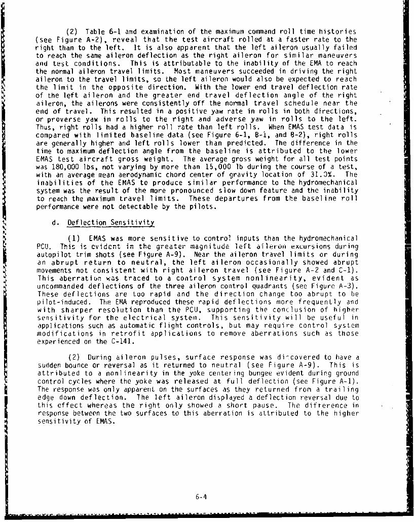
(2) Table 6-1 and examination of the maximum command roll time histories(see Figure A-2), reveal that the test aircraft rolled at a faster rate to theright than to the left. It is also apparent that the left aileron usually failedto reach the same aileron deflection as the right aileron for similar maneuversand test conditions. This is attributable to the inability of the EMA to reachthe normal aileron travel limits. Most maneuvers succeeded in driving the rightaileron to the travel limits, so the left aileron would also be expected to reachthe limit in the opposite direction. With the lower end travel deflection rateof the left aileron and the greater end travel deflection angle of the rightaileron, the ailerons were consistently off the normal travel schedule near theend of travel. This resulted in a positive yaw rate in rolls in both directions,or proverse yaw in rolls to the right and adverse yaw in rolls to the left.Thus, right rolls had a higher roll rate than left rolls. When EMAS test data iscompared with limited baseline data (see Figure 6-1, B-i, and B-2), right rollsare generally higher and left rolls lower than predicted. The difference in thetime to maximum deflection angle from the baseline is attributed to the lowerEMAS test aircraft gross weight. The average gross weight for all test pointswas 180,000 lbs, not varying by more than 15,000 lb during the course of a test,with an average mean aerodynamic chord center of gravity location of 31.3%. Theinabilities of the EMAS to produce similar performance to the hydromechanicalsystem was the result of the more pronounced slow down feature and the inabilityto reach the maximum travel limits. These departures from the baseline rollperformance were not detectable by the pilots.
d. Deflection Sensitivity
(1) EMAS was more sensitive to control inputs than the hydromechanicalPCU. This is evidcn-t+ in the greater magnitude left ailero,' excursions during
autopilot trim shots (see Figure A-9). Near the aileron travel limits or duringan abrupt return to neutral, the left aileron occasionally showed abruptmovements not consistent with right aileron travel (see Figure A-2 and C-1).This aberratiun w:as traced to a control system nonlinearity, evident asuncommanded deflections of the three aileron control quadrants (see Figure A-3).These deflections are too rapid and the direction change too abrupt to bepilot-induced. The EMA reproduced these rapid deflections more frequently andwith sharper resolution than the PCU, supporting the conclusion of highersensitivity for the electrical system. This sensitivity will be useful inapplications such as automatic flight controls, but may require control systemmodificdtions in retrofit applications to remove aberrations such as thoseexperienced on the C-141.
(2) During aileron pulses, surface response was di-covered to have d
sudden bounce or reversal as it returned to neutral (see Figure A-9). This isattributed to a nonlinearity in the yoke centering bungee evident during groundcontrol cycles where the yoke was released at full deflection (see Figure A-I).The response was only apparent on the surfaces as they returned from a trailingedge down deflection. The left aileron displayed a deflection reversal due tothis effect whereas the right only showed a short pause. The difterence inresponse between the two surfaces to this aberration is attributed to the highersensitivity of EMAS.
6-4

e. Degraded System Performance
The three pilots that flew the modified aircraft were unable to detectany difference in the feel of the control system or aircraft response in singlechannel operation. Aileron deflection and roll performance during degradedsystem rolls with first one and then the other channel of both actuatorsdepowered were comparable. Roll performance was comparable to the fully poweredconfiguration in low dynamic pressure conditions but degraded with an increase indynamic pressure as expected (see Table 6-2 and Figure A-5). No uncommandedaileron movement was seen as a consequence of deactivating or activating a singlechannel.
f. Tab Operable Roll Performance
(1) With tab operable selected on the left wing at 200 kts and 9,000 ft.,approximately 30 lbs of force and 45 deg of yoke deflection was required tomaintain level flight. Right aileron tab required 45 lbs and 55 deg. At 200 kt.sand 20,000 ft these values were 30 lbs of force arid 40 deg with left tab, and 65lbs and 50 deg with right tab. This difference is caused by the higher forcesrequired to backdrive the aileron against inert motors, resulting in less ailerondeflection at the neutral condition (trailing edge up zero hinge moment state,see Table 6-3 and Figure A-5 and A-6). Comparison of roll performance with tabselected on the left aileron and tab on the right for rolls in the same directionat identical test conditions but in the two tab scenarios (see Table 6-3 andFigure A-6) indicates that no degradation in performance has occurred. Baselinetab data is provided in Table 6-3 and Figure B-2, B-3, and B-4 (the baseline tabroll data corresponds to tab selected on both ailerons).
(2) Roll-off resulting from the selection and de- 3 election of tab wasfound to be similar in the two scenarios but for the final aileron positionbecasue of the higher backdrive force requirements of the EMA (see Figure A-6 andA-7). This roll-off is a consequence of the unpowered aileron floating to a zerohinge moment condition that is approximately eight deg trailing edge up.
g. Aileron Damping
(1) Aileron damping was found to be high or deadbeat at all testconditions (see Figure A-9). Wing accelerometer response to the aileron pulsesand maximum command inputs showed evidence of a structural mode superimposed onthe input response (see Figure A-9 and C-1). This was not considered critical.The intial part of the wing response show a high frequency oscillationsuperimposed on the wing trace. This is believed to be caused by vibration ofthe cantilever accelerometer mount. Wing response was considerably greaterduring maximum command rolls, however inertia overshoots are also included inthese oscillations (see Appendix C).
(2) Aileron pulses produced increasingly greater bank angles, from threeto 13 deg, as altitude increased. In general, right pulses produced less bankangle than left pulses by approximately two deg. The aircraft slowly rolled tolevel flight after the pulse. At 35,000 ft PA and 0.81M, and at all 41,000 ftairspeeds, left pulses produced bank angles that required pilot action torecover. These differences are nrt attributed to an EMAS effect.
6-5

h. Autopilot Interaction
(1) The test team had originaly intended to use the autopilot turn knobcontrol for a roll input, but the A/P would not function reliably in this mode.Therefore, the rolls were made in the NAV SELECT mode by moving the heading bugon the horizontal situation indicator (HSI). This limited roll attitude to 30deg of bank whereas the normal mode was expected to produce 38 deg. Regardlessof test conditions, maximum aileron deflection was approximately five deg andmaximum roll rate was approximately three to four deg/sec (see Figure A-4). Theautopilot malfunction precluded the accomplishment of autocoupled approaches.
(2) The left aileron made greater deflections than the right in responseto the small autopilot inputs. See paragraph 6d for EMAS sensitivity toautopilot trim shot commands.
i. Takeoff and Landing
Takeoff and landings were normal and no irregularities in the data werefound. No data is provided.
j. System Failure
(1) 85% of the flight test was successfully completed. Testing wasterminated on the sixth sortie because of an EMAS malfunction that could not becorrected in time to complete the program prior to scheduled aircraftdemodification. Up to that time, the system had performed flawlessly during theflight portion of the test. The inflight malfunction was ch.....tcrzd by threechannel A drop outs. The first drop out occurred during a maximum command leftroll at 174 knots airspeed (Ve) at 35,000 ft PA. The next drop outs occurredduring maximum command left and right rolls at 190 kts (Ve) and 41,000 ft PA.The indicated faults for the last two drop outs were position in limit and 200 Vfor greater than two seconds. The faults for the initial drop out could not berecorded prior to channel recycle. The channel recycled without difficulty andthe aircraft returned to base without incident.
(2) During ground testing to isolate the fault experienced in flight,the following events occurred:
(a) Event 1: Initially less than maximum rate and then maximumrate aileron inputs were made until channel A dropped out. No data was recordedduring these cycles.
(b) Event 2: During a maximum command left yoke input, the ailerondeflected at a higher than normal maximum rate to the trailing edge up electricaltravel limits, without a slow down, and shut down automatically. Motor speedswere abnormally high.
(c) Event 3: Without yoke input, channel 8 was powered up from thepilot overhead switches. The aileron began to move up at lower than maximumrate. During this excursion, channel A was turned on at which time deflectionrate increased to higher than normal maximum rate. The slow down feature worked,fhowever the aileron went to the electrical travel limits and both channelsautomatically shut down. Channel A voltage command displayed an abnormaloscillatory response before the shut down. Motor speed was normal.
6-6
ILI II I

(d) Event 4: Without yoke input, channel A was powered up, as inEvent 3, and the aileron travelez' at higher than normal maximum rate to the fulldown electrical limit and ':utomatlcally shut down. Channel B was not poweredduring this excursion. No sliw down was evident and motor speed was normal.
(e) Event 5: Both channels were powered up and the aileron movedat lower than maximum command in both directions without incident. Maximumcommand trailing edge up was executed without incident. Upon maximum commandtrailing edge down input, the aileron traveled at higher than normal maximum ratewithout a slow down to the retract mechanical stops. The stops were engaged withsuch force that a material failure occurred. Both channels automatically shutdown.
(3) The retract mechanical stop engagement resulted in the screw endfitting being sheared. The tab on the actuator housing bottomed out on the endfitting and bent outward (see Figure 6-2). The end fitting tab had been designedto fail at a lower load than the housing tab. This demonstrated that the fittingserved as a backup mechanical stop. The last forceful stop created enough momentto allow the nut holding the B otor resolver against an orientation pin to backoff from a restraining lock (safety or tine) washer. The resolver moved forwardand the pin fell out of a tight press fit through the motor shaft. This allowedthe resolver to change orientation and created multiple problems. After thisdamage was repaired, the basic fault that appeared to have produced the inflightdrop outs remained. This fault was a current imbalance, evidently caused by aphase error in motor A. This fdult was not evident in data from previous flightsand only became critical during high deflection rate situations with low airloads such as in a maximum command condition at low dynamic pressures; Just theconditions at which the inflight drop outs occurred. This however, does notexplain the motor runaways without inputs experienced in the groun6 tests. Theresults of contractor laboratory evaluation of the EMAS failure were notavailable prior to publication of this report.
k. Structural Design
The mechanical stops on the actuator were not required to be designed towithstand the loads imparted by a stop from normal EMAS maximum travel rate,programmed to be identical to the normal PCU system maximum rate. The EMAS wascapable of producing higher deflection rates when unrestrained. The inability towi thstand the normal or unres trai ned max imum deflIect ion rate i s not a Ilogi caldesign criteria and defeats the purpose of the stops.
6-7

Table 6-1 Maximum Deflection Rolls
Yaw Rate prior to + = positive
rudder coordination (R) = rudder coordination
(N) = no rudder data
Airspeed Altitude Roll Time to Max LH Max RH Time to Time to YawRate Max Rate All Oef Ail Def Max IH Max RH Rate
kts ft deg/sec sec deg deg sec sec deg/sec
204 9,200 -17.5 1.9 23.0 -13.0 1.3 0.5 -0.3 (N)
208 9,200 22.0 2.0 -13.0 24.5 0.9 0.8 -0.5 (N)
255 9,500 -19.8 2.0 22.5 -12.0 1.3 0.6 0.3 (N)
263 9,500 23.2 1.9 -13.0 24.0 0.9 1.0 0.7 ,N)
335 9, 0 00 - 13.5 2.6 21.0 -11.5 1.5 0.6 (R)
335 9.000 17.0 3.2 -11.0 21.5 1.0 0.8 (R) ,
195 2(-.600 -19.5 2.7 23.0 -13.0 1.3 0.7 0.3
187 21.300 21.0 2.0 -13.0 25.0 0.9 0.8 0.7
250 20,500 -21.1 2.0 22.0 -13.0 1.4 0.7 0.2
252 2C,200 24.6 2.3 -12.5 25.0 1.0 J.0 0.6
333 20,,500 -13.7 3.2 20.0 -13.0 1.2 0.7 0.5
332 20, 300 16.5 1 1.6 -11.0 21.5 1.0 0.8 0.2
160 36,500 -20.6 3.1 22.5 -14.0 0.9 J 0.7 (R)
"160 3(,500 20.5 3.3 -13.0 25.0 0.9 0.8 0.8
?65 3'*,M0 -20.3 2.7 21.5 -11.5 1.3 0.6 0.7
265 35,900 23.1 2.6 -13.5 24.5 1.1 1.0 0.5
280 35.000 -18.1 2.7 23.0 --13.5 1.3 0.6 0.8
279 3,00O0 211.8 2.7 -13.0 24.0 0.9 1.0 1 0.3
186 40,500 -18 6 2.0 23.9 135 (R)
186 40,500 21.0 2.0 -13.5 24.0 0.7 0.6 0.5
6-8

Figure 6-1 Baeeline/EMAS Roll Comparison
MAXIMUM DEFLECTION ROLLSIANK-TO-BANK
CRUISE CONFIGURATION EMAS DATABASELINE (FROM REF. I) APPROX. 110,000 LB GROSS HEIGHT
- ROLL RATE 0 LEFT ROLL 0 RIGHT ROLL
--- TIME TO MAX RATE0 OROLL RATE 8 OTIME TO MAX RATE
10,100 AND 11,000 FT ALTITUDE?54,000 AND WI,000 LB GROSS WEIGHT
00
0 -- " 0 _ 1 1 1 1 1 1 I 1 1 1 1 I I I I_10 ai0 260 210 300 320 049 360
IW C;,ATED AIRSPEED IAS •
35i,700 FT ALTITUDE151,0110 Ll 6ROSS WE1GHT
30-
Im dl1
.*.
o..--
0.71 0 .05 0. 110
MACK NUMBEr
IN;AT- ARSED9 A

Table 6-2 Degraded System Roll Performance
Yaw Rate prior to (R) = rudder coordination
rudder coordination (N) = no rudder data
x/y Off = EMAS Channel x & PCU System y Off
Roll Time to Mex LH Max RH Time TO lime To Yaw Conditioni.'r pS. Altitude Rate Max Rate Ail Def Ail Def Max LH Max RH Rate
KtS ft de9/sec sec C deg .e sec sec deg/sec _
19K 9.100 -17.5 2.3 22.9 -13.5 1.3 0.6 -0.2 (N) All Off
190 9,100 20.0 2.3 -13.5 25.0 0.9 1.1 0.? (1
9, 100 -17.7 2.3 2i.7 -13.7 1.3 0.7 -1.2 (l B/2 Off
1'. 9,000 19.8 2.3 -14.0 25.0 4.8 1.0 0.5 (N)
330 9,000 -11.5 1.3 18.3 -10.5 0.6 0.5 -0-4 All Off
t i. 900 14.9 i 1.6 -10.8 18.5 o.6 i 01.6 (R)
Jj, 9,000 -. 0 1.6 18.4 -10.5 0.7 0.6 (R) 8/2 Off
-J4 9,000 14.6 2.0 -11.2 18.5 0.5 0.5 (R)
19', 20,200 -17.4 2.0 21.8 -13.3 Li 0.6 -2.0 All Off
199 ?0,3u0 21.3 2.6 -12.9 25.0 0.8 1.3 0.9
197 20.400 -18.6 2.1 22.3 -13.5 1.1 0.7 -0.3 B/2 Off
19? 20.500 20.3 1.5 -13.3 24.9 0.8 1.0 -0.2
334 "0,500 -11.1 1.7 17.0 -9.5 0.8 0.5 0.2 A/, Off
334 /0.400 13.2 1.5 -10.2 17.3 0.6 0.6 (R)
3hi ,0,500 -10.3 1.2 16.8 -9.3 0.4 0.4 (k) 8/2 Off
334 20.500 11.6 2.0 -10.3 17.2 0.4 0.4 (R)
ifo 36,600 -15.1 1.3 22.1 -13.6 0.5 0.6 1.0 A/I Off
160 36,600 17.5 2.0 -13.0 25.0 1.2 0.9 (R)
16? 36,600 -14.8 1.6 21.5 -13.5 1.1 G.9 -0.5 8/2 Off
161 35,500 18.1 2.3 -14.0 25.0 0.8 1.0 -0.3
2. 35,700 -10.5 2.3 12.0 -8.2 1.7 1.5 0.0 All Of.
?8 35,700 15.9 2.0 11.8 18.5 0.9 0.8 0.0
35,606 -15.4 i 1.6 20.0 13.0 1.4 1.1 -0.2 8/2 Off
* 35,600 15.5 2.6 - 11.? 18.3 0.6 0.8 -0.2
Ili? 40,700 -14.) 2.0 1/.0 -12.1 1.1 0.8 0.0 A/) Off
i23 40.700 16.5 2.3 -11.2 16.5 1.0 1.3 0.3
40,100 -16.8 2.0 19.0 -13.5 1 .1. -0.3 8/;, Off
I,. 4U0500 19.5 2.3 -1?.5 2 1.8 0.9 1.4 0.6
6-10

- -C,
M 0.
Cc -j. 0 0'
to 0. -J 0
"UhU
99V6 CA 'D 0 %a co-
m. -m a, a0
10~o c'. 0 L .nu
o ~ t 0 w0 ~ 0% --
@3 - c'j C4 - l a li
a. 0% ' a.' 430
.. '
0) --
0= ___ 1 10 10I- 4.34.3C l
04% 17 a., ) W
L ~ CL* " 0'' ON do C)33 0 .' ~ xo *l WcL3 .ý a
- * ~ -K
S.. 6-11

VIM.
Figure 6-2 EMA Mechanical Stop Damage
6-12

CONCLUSIONS AND RECOMMENDATIONS
The EMAS flight test successfully demonstrated the feasibility of powering aprimary flight control surface with an electromechanical actuator and tailoringit to specific performance requirements. It has shown that the installation ofsuch a system into a pre-existing airframe can be effected without structuralmodification and with only minor electrical changes. Specific conclusions andrecommendations are given in the order presented in section six with theappropriate page number in parenthesis.
1. A single aileron electromechanical actuator (EMA) can be installed in aC-141A without structural modification to the airframe and without changes to thecapacities of existing electrical and hydraulic systems.
2. A dramatic failure of an EMAS system has the potential for producing unusualflight attitudes and motion rates making it difficult for the flight crew toreach system circuit breakers.
CIRCUIT BREAKERS FOR FUTURE INSTALLATIONS MUST BE PLACED IN THE COCKPIT WHERETHEY ARE ACCESSIBLE TO THE FLIGHT CREW DURING EMERGENCIES. (see page 6-1)
3. A single electromechanical actuation system (EMAS) channel displayedsensitivity to the momentary loss of power during power source switchingoperations, such as switching from aircraft to yrournd power, It could not Dedetermined if this fault lay with EMAS or the airc-.aft.
4. The EMAS travel limit and electrical stop settings drifted. This created thepotential for inadvertent system shutdown until the difference between the twosettings was increased.
FUTURE SYSTEMS SHOULD ELIMINATE THE TENDENCY FOR ELECTRICALLY-SET DEFLECTIONLIMITS TO DRIFT. (see page 6-1)
5. Sudden movement of the aileron during initial power up with the surfacedeflection not in the proper position relative to the yoke may present a hazardto ground personnel. This is also a characteristic of the standardhydromechanical actuator, but the nature of the electromechanical actuator mayallow a remedy to this hazard.
FUTURE SYSTEMS SHOULD INCORPORATE A MEANS OF ELIMINATING THE INITIAL POWER-UPMOVEMENT HAZARD WHEN AILERON AND YOKE DEFLECTIONS ARE NOT COINCIDENT. (see page6-2)
6. With the EMAS unpowered, higher forces were required to move the left aileronthan the right.
FUTURE SYSTEMS SHOULD HAVE UNPOWERED BACKDRIVE FORCES OF LESS THAN TEN POUNDS TOEASE MAINTENANCE TASKS, (see page 6-2)
7-1
-T • '1• " I'• , • • • • 1 ' • • '•i•' -, - , ,n , ,~ , ........... ............ ....... ...... .. . ... .. ..

7. Manual positioning of the control surface by rotating the actuator ball nutwas not possible in temperatures approximately below freezing. The loss of thiscapability may hamper maintenance actions.
FUTURE SYSTEMS SHOULD CONSIDER MANUAL COLD-WEATHER POSITIONING OF THE ACTUATOR ASA DESIRABLE FEATURE FOR EASE OF MAINTENANCE EFFORIS. (see page 6-2)
8. Control surface EMAs have the potential for disturbing flux gate compasstransmitters normally placed in wing tips and tails.
FUTURE INSTALLATIONS MAY REQUIRE THE RELOCATION OR IMPROVED SHIELDING OF FLUXGATE COMPASSES TO ELIMINATE POTENTIAL INTERFERENCE FROM EMA ELECTRICAL FIELDS.(see page 6-2)
9. The EMAS installation and operation did not alter the damping of the aileronor wing structure.
10. The maximum EMAS current draw of 12.5 amps during the flight test wascompatible with available excesses on the aircraft buses; however, futureretrofits to existing airframes may require electrical system changes to handlethe increased requirements for emergency supply.
11. In flight and on the ground, the EMAS aileron actuator bay temperature wastwo to seven degrees Centigrade cooler than the right hydraulic actuator bay. Nothermal gradients were observed during any maneuvers.
12. During fully functional EMAS operation, the roll control system felt normalto the pilots and the data indicated that the system duplicated thehydromechanical actuator performance with both pilot and autopilot inputs, butfor the exceptions noted in this section.
13. The EMAS slow-down feature for aileron deflection rate approaching travellimit is more pronounced than that for the hydraulic PCU and resulted in the leftaileron requiring an average of 0.3 seconds longer to reach the same deflectionangle as the right aileron for similar test conditions. This contributed to adeparture from normal aircraft roll rate but was not ,!vident to the pilot.
14. The EMAS reduced aileron travel rate coming rff the surface travel limit.This is not a useful feature.
FUTURE SYSTEMS SHOULD NOT INCORPORATE A REDUCED TRAVEL RATE FOR TRAVEL OFF OF ADEFLECTION LIMIT STOP. (see page 6-4)
15. Right rolls occurred at a higher rate than left rolls and also higher thanbaseline roll rates for maximum command roll inputs. Left rolls were at a lowerrate than baseline. This is attributable to the lower deflection rate of theleft aileron near the travel limit and the failure of the EMAS to produce themaximum aileron travel.
7-2

16. The EMAS-driven aileron made more small position corrections than the nornmalaileron system during autopilot trim shots. The EMAS-driven aileron also madesmall deflection excursions in response to control system aberrations that thehydromechanical system did not repond to. These excursions were not felt by thepilot and did not affect roll performance.
FUTURE SYSTEMS MATED TO A MECHANICAL CONTROL SYSTEM SHOULD CONSIDER THE INCREASEDSENSITIVITY OF AN EMAS TO SMALL CONTROL SYSTEM ABERRATIONS THAT MAY PRODUCE SHARPSURFACE DEFLECTIONS INCONSISTENT WITH CONTROL INPUT. (see page 6-4)
17. Deactivation or reactivation of one of the two redundant channels producedno aileron motion. Single channel performance was comparable to dual channeloperation.
18. Aileron tab operable tests indicated that the EMAS installation resulted inno roll performance degradation for single aileron powered configurations. Theincreased forces required to backdrive the unpowered EMA as compared with thehydromechanical system resulted in a less severe asymmetric control yokedeflection and less control force with tab operable on the left aileron only.
19. EMAS interfaced with the autopilot without difficulty but displayedincreased sensitivity to small autopilot inputs.
20. Takeoffs and "iandings showed no abnormal aileron behavior.
21. The EMAS suffered an inflight fault and, during a subsequent groundincident, experienced motor runaways with and without control inputs.
22. The emergency mechanical stops on the actuator were not designed towithstand the impact forces of the programmed normal maximum travel rate or theunrestrained full motor capacity travel rate and failed during a ground incident.
FUTURE SYSTEMS SHOULD INCORPORATE A PRIMARY ANO BACKUP MECHANICAL TRAVEL LIMITSTOP THAT WII L WITHSTAND FORCES IMPARTED BY A FULL MOTOR SPEED IMPACT. (see page6-7)
7-3 (7-4 blank)

LIST OF ABBREVIATIONS
Item Definition Units
AEA all-electric airplane ---
AFWAL Air Force Wright Aeronautical Laboratories
A/P autopilot ---
C Centigrade C
CE Controller Electronics
CWS control wheel steering ---
DC direct current Amps
deg degrees deg
EMA Electromechanical Actuator ---
EMAS Electromechanical Actuation System ---
EMC/EMI electromagnetic compatibility/electromagneticinterference
F Fahrenheit F
GeLac LGckheed-Georgia Co. ---
GVT ground vibration test ---
Hz Hertz Hz
ILS Instrument Landing System ---
KCAS Knots Calibrated Airspeed knots
M Mach M
MILSPEC Military Specification
PA pressure altitude feet
PCU power control unit ---
q dynamic pressure lb/sq in
RVDT Rotary Variable Differential Transformer
8-1

LIST OF ABBREVIATIONS (continued)
Item Definition Units
T.E. trailing edge ---
VAC volts alternating current volts
VDC volts direct current volts
Ve best endurance airspeed knots
8-2
REFERENCES
1. McCabe, J. M., Capt, USAF and Benefield, T. D., Maj, UASF, C-141A Catejory IIStability and Control Test, FTC-TR-66-5, Air Force Flight Test Center, EdwardsAFB, CA, June 1966.
2. USAF Technical Order IC-141A-2-1GA-2, Flight Controls.
9b
9-1 (9-2 blank)--

APPENDIX A
TEST DATA
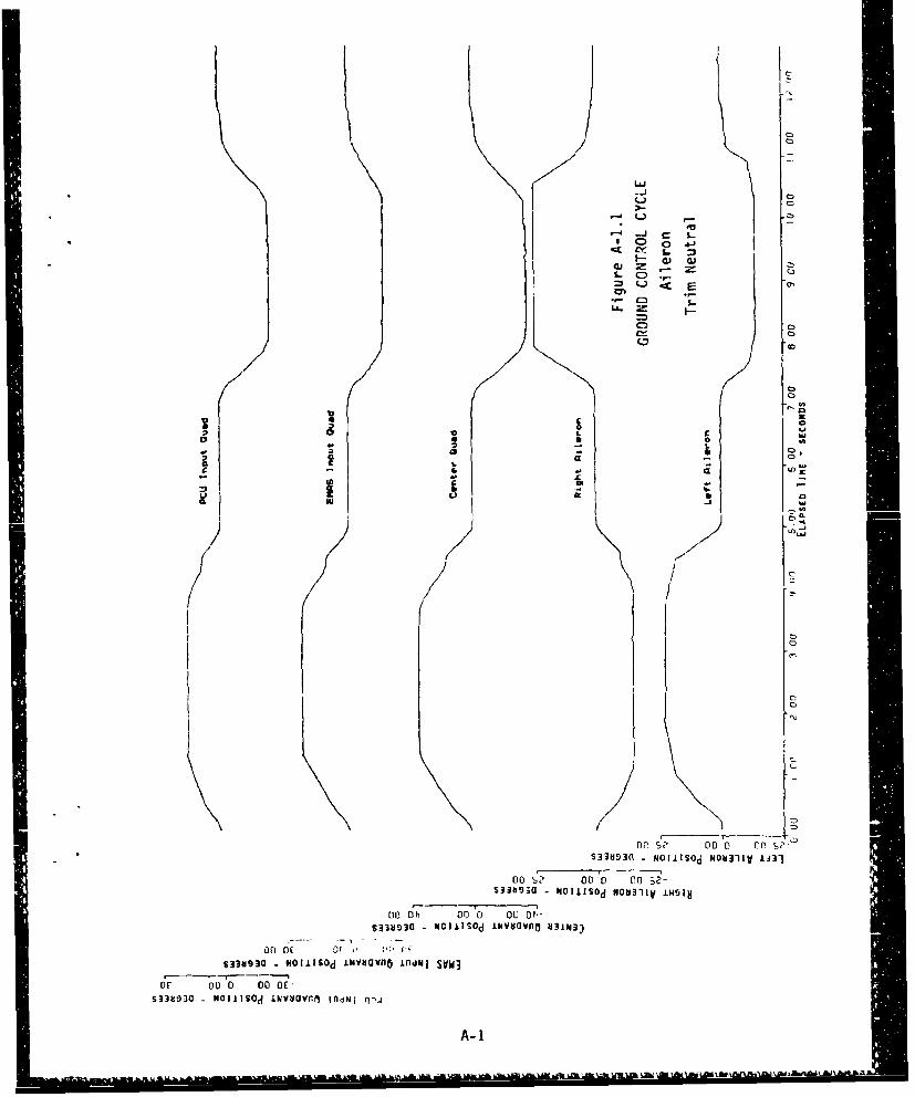
Cn
Co 0 41Sr . =
£C)
C)
CCa
10
9.
op 0C 0 0, "S3H3 - 0OISdNN1VII
00 aZ o" 05
Mbi N mmI~ NON11 -N1
OFl O? 00D 0 £0S33N9310( - Nollisod NOYVG1Iy ti431n
A 0-100 0 ~
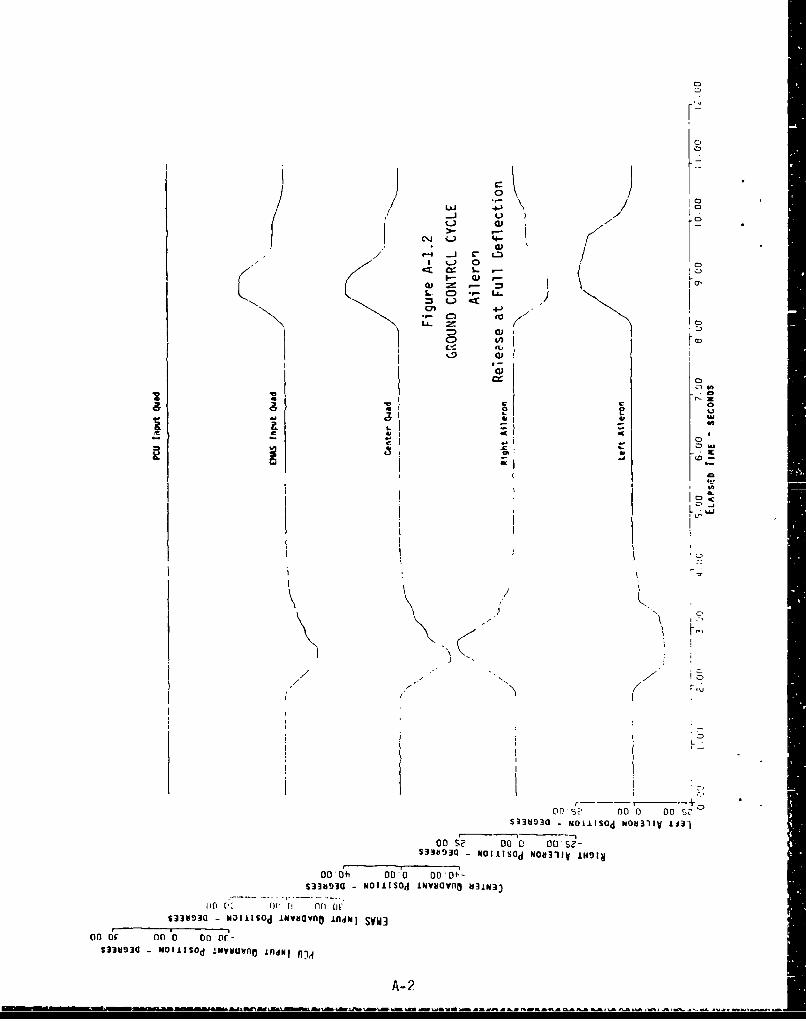
00
00
.L
01) -, dh co' -ý
LL. f! (r 0$33030 OI'I~d wvvano nimlSVW
co 6c c 'D O Dr.'S33usla~~ ~ ~ ~
WIISdi~vvoinN
*1A-2

ICE
C>0 0
m c
-C Ca
Do -c DOs0-o~ - -cLSdWO lyL3
oo6, D -0 M bI-
S3393 N-isdivvvovj3
Do 6c or 'o on-IJ
SiW3 - OIJA~d mygaPO ndulSVu
oc~~~ or 0 VDW
s~aw m "0 11S~ Llivavn i-o* n- A-

La.J 4-oF-J u.1 ~ Q
Ie- S - 41JU d L.i
CI Z I L"
4.JJdxw
- -y -- -- -- - I00 00' 0 ,
00 -6 -" oa/13sl -~ }011u IN--fl NUM
-- ---
01,E co 0 00CC-
uogtio J~M~no fl~J fjdA-4

C3
L&0
Laj
U-)
cc4 CD 0al L
1- Cý
La-f
cr--
Qw
o AL
C2,.
C0
M
Q0
0001 0000 0Oý- O00~-0S334S93a '010tlOd w3oond
A-5
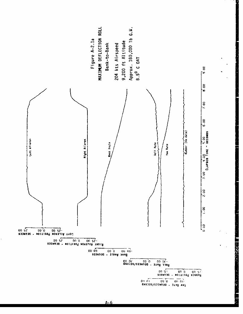
OCD
-4 0Z
* . to 4-) VL ~ ~ ~ C s . -.C~~8% CL Lh .41
0) LI 0 1. Q.
z ~ 00
01
C)
00L
- £C)
CD
Do 00' 00-J
S33V30 MILISd NO311VIs0
00 c 000 0 no c0S33M93~ -WOGlISJd OUIIV ul
00*ý £?-7 onl 0St3fl~~SMS -~il~ 0o3iodHa3Iyi4h
000) 00 0 00 (1-
13 W 0- 6 319NV/
3393 - 3 VSVQ

-LJ%n 4-0 U
~L4-() CD
4.) -ý
04 Cf 4
to ' 0.u
CC
0010 cc se
4,-ý 00
4m 00
S
on -
C-i D 'n c
C0) oma* 0 , 1
A-7U

C>
.LJ CO CL - C
* i (.. 0~ 4-1JLa-O 0)- I
=~ fa 4. 4c
OJLL 0 0 - -LLAJ t 4 -j *.4-.
co _x 4-ý 0.,-> S i ' - 1
Ln LO CL r- -
0
07
10
r ... ...............
Colo 0 s0
00~ - Ko)' nS?
00 09 0 0
S33030 "l"So M3 00
0o0 ODS0 00-
aNo33S/S33S930 - 3±WN AVAo
pns nln A ~

_jI
.)L- 0~WJ +j - z 00
LL eo a 41CD1 % 0
m Ln LL o a%.-0 CDcli &n <a 0;
* 0. D* a
01
ED
Jýa
IC
4I co,6
453io 31k IV
cc dc .4. '0 Go c
U A-9

-)
_j 6~ " +- .C
LA. f0 CJ4 ) c ý-
CI -4 CD4)
LL. 4J .
UO-1 C 0 0.KD S
C3U
CD
00 00- 00 S?833493C~~~u WCA2d ODIVL3
00 00" 00 S0NOILI~d w"311VIme0
33U93a3NO 31M NOIWJ ova L
on6c 01 D 0 c000 033/3190 gie9-0
$333"30 -3191y NNVQ
of, 0 1 0 n' on Oi
GNO33S/S)33930 - give PIVA
A-ia

C)i
LaJ CL 0. .-
GLL. 0 CD .
ca I
LL =3 m4 *L.)
cc 0) 0.(C) Uh LO( 0%
CD
r'.
0j
co ~ ~~ Ur 0 e$330930~~~~ VOAMlNV1Y NI
co C~ 00 0 Do 09
00~~ ~ ~ ~ ~ 61 oMl- 0.0
-,3SS3ta - 31NCv
0. A-17
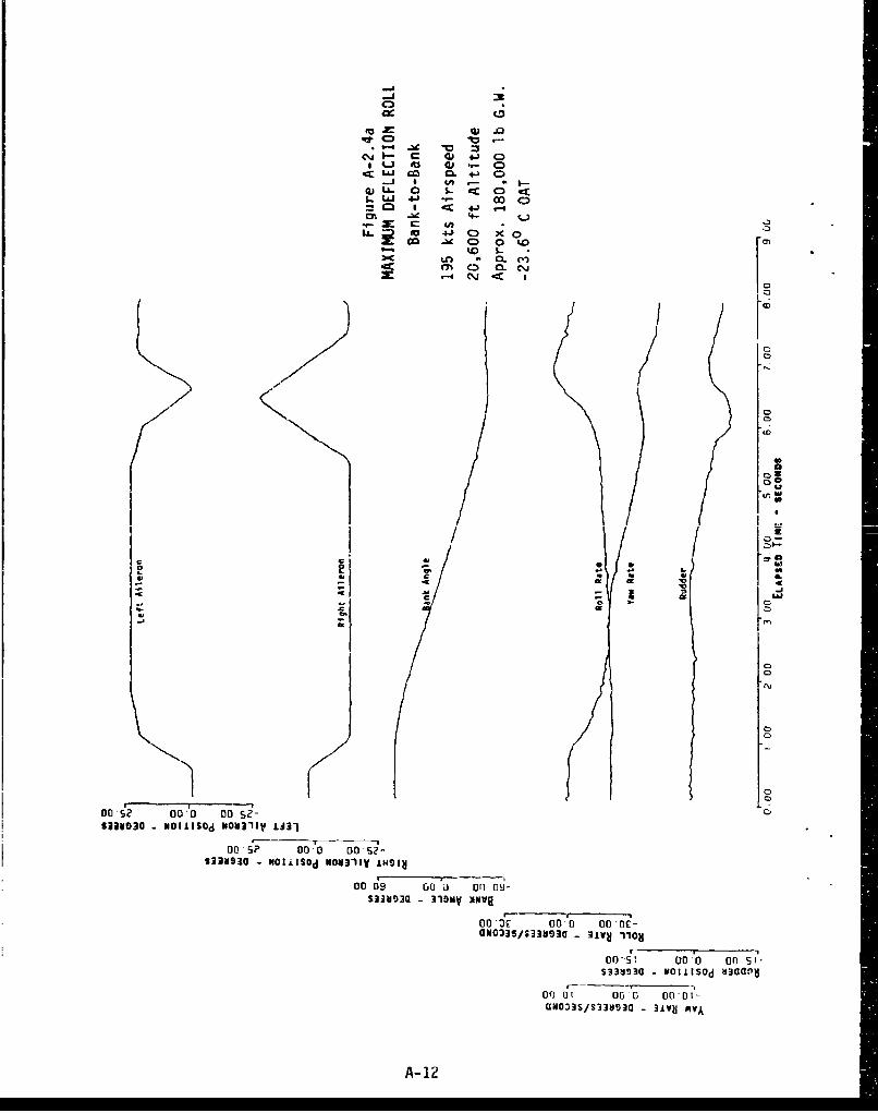
c~~j 4) 43 C)
gI~ f-) 03.- 0qc: S.J cO. 06 - :
-i I U) - . I.-
S-LLJ 4.' 00 C-10=~ .ý 4J .-I
L- to 4jC L
a 0 w
00
w
44.~
IC 2 [cu
CC
- Iu
00-01 CC
oo.d 00'a 0'1c
A-1

C)
LL co C 4-J
0 LA.. 0 CE~ CcLLIJ 4-) co C 0
00 x CD 0i 0 O>C rl CL
00C 1 l 5.-.I C
~0 QC'3~(%4~m
LJ
7en
7r
------- - C
00"0 0 SD
NOIA~~d Nulli lia
00 S? 0' ýl OD aa
4.O3SS3N3 31V 110
on on o on
*N)SS3S3 - 31Y 1YA
A-13

2c 0) +'
Q Ji ) 4-) CDL3J go ab CD
0 LL.. 0 c) -ccI-LLJ 4-' Cl~
=h M 4-SO -4
2: 0o C 0 r-
U010 0-cc
III
e -en
Cý
00 - 000*' 00-S?- C
no S? 00,0 Go-sz-531ag3a -maIlisad woulty IH9Ia
00,09 00 0 ( 009-
Of)"Ic 00 0 WfOE-Oi0~3S$/s31aq3G 31vag 1108
cnssi anv on s-633V930 - h11ilsd H300nH~
on al 00o0 00a-0GN0335/133V930 - 3LvN VAA
A- 14

Lc
0) .- oý
.) ;.6 S- < ) C
'U 0)*- 00C
in a- < ~ 4-
tm 4- C)
co 'U x+ C) )e'~j -M O
('. . CL ')N
U-) C QL 0
j [!Ion
.- 000 0
23V3 MC110 W031VL
_ _ _6
00 ' D 9
£33~~33H9Q 31- XkVG~ OM1W
00 S? cc 0 0o St-
00f9 ..Or) 0 on 1)0-
S338ý30 N- ilshd H.aan00 00 000 0 -
GN3/S3~OQ -I' 3Jj 383a- 0N8 V
A- 15

-,J
LLJo -oo
S-I LL 4- 0J -cc
tn .1c -
'ZJ 41 CD x~ Dco 4ýz Cl0 a
-Lfl %1 .-.
Cl) C\J4
40
j
az,
ou sa0S33M3C N1116d NO311VIA3
ON03S/S3893a 3ivUI-I-
4,)SS3U3 - 31Y OVA
A. 164
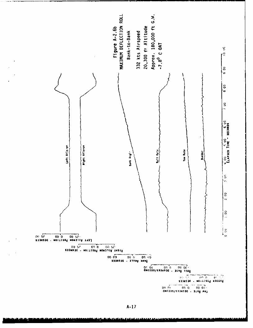
C-4
I4A 4
.A- -x
:C C6-h
* (~) u 4)D
~ a~ C4)
~.l a ..
*1U~ 0 -~ 'A
::1 1 th
Law0 Will10
C',
00,101 00 S0
Noval0
co S, on C C;-, si
S1343a NIIISd MOIIIVINSI
00 69 00 0 n fi
aln SS3OC- av I
A-17¶US-1 HL14LAAAA HAZ&A

C)
La-0
1. -C D c
C3 .0 -Cc +
21-j co -u C) 0
g(..I C0GI r
,~IjJ~O.4~.. J * Ub -* I5
QjLI. 0 1. .~ 0
1~Ij. 4~) e- :,'0~L ia ,
'- a
Ql
113S3 ( U )C~ 091V M100-09 00 0 c 09
or)~~ ~ ~ ~ -lo)'c O
A- 1-

C>.
e'J1 W 4J 0lq-) 4) CDe
~j I tn .-
0 5-ccC)C4.. cE4.) 0C~ .t 0 *0
- r f1 1..x r-.C
ca hco a.
CD
CD
U0
pý w
4-, - 0 1v CL KI0 I
DOS. C)
N3U3 oillSO'd MON311V 1.431
(3o-S?' or' o no) s-NDN3a-MILISOd WOVIlIV IHNIN
oo-6 o L 'oo cc n-)S33NSr -----------M~
or Oc 000 000OE-
nr on 5S33;193G - OIItSOdj 8303cI
onr) di~ 000 f)01-
A- 19

CC,
cc0
CO O .4~
aLJ 0o CL 4 0
ca I c 4-3 -m,4- CC
co CD 0 00cC L
toLin C.
CD
CD
to
Co aL a
C II
CC Cie 1
00 ~? 000 00 s-/"S393 OilISOd WC31 .IJ31
00o $L' 00 0D 005?i-233"930 - mNOi.lsOd MOU311y IN9I8
00*09 0O 0 00 09-saissac 319.ay %NV8
aNo33$S/3b3u90 3.LVJ 11O8
filn ) oni -pS315193a NOlilsOd a3Uand
0 r) 0M Or0 0Q,0i-ON003S/S33&iý)9 - 31Ve IVA
A- 20

r-a
LAJ~~~ co C 4 :
~LIJ 4. 0.- CD=I I -CC -4J I
LLIJ x. o- m
2-6 CC _Ile 0
:K LO 000ýo Lnl 0 CL J
n0
TL
)o 00C'
00S 00 OS?- cc0 ,
$3341936 UOIiIS5Od8004311V iHSIM
eOS6' 00 0D 00 s6-S33 ~ ~ S3US3 31N NONSONOVEV 4I
000 c0 00 00 0-cc
aNO33S/S33al9j3J 31VUj 1108f
nnsi o nW on51S33M8i3G NOilIsOd &j3one~
000! 0fan0 00 0!-ON033S/S33HO30 - 3.±VH sjvA
A- 21
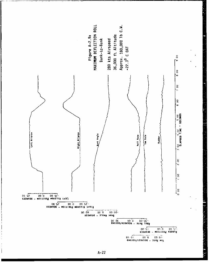
LJ CO IM 0 )C
-j I CA o-0~~0 1-0 S 0 CD
LLAJ 4J.- c COim I -c-C -
m 4-3 0o x0.co or C 0f
D . CL
cma
C_41 cm
ODa, 0 0
Do a? 00 'o on
$3193 -"3il~ MO31 V
6,03 001,0 Nif"1"
()o 0 00 0 00,00
oc de 00 'o 00 oe
amons633V90 3iv 110
on-ýl o r of) c, 1
S33~QOý3/393 - 31VISý m031A.43
00 SC 000 0A-S2

-D
-J-
to 4J C>
Cý C ý. S. 0
L ah .- % 0 Cl~
*%. C-) 4z
301
0049 ou 'o0000a
-1V3 - KmvAV
o'))
0009 00 00 00-ON03S/S3S93 - 319MW Iq
A-2300 0E

C5M-C
o) w z0 .0
I L.) a). CD-r U~j 06 4-) 0)
i w. 0' L C0;U. :2o- S- ax
4m-
LL = 0 41 0) Xi- - 0 0ý
:.-4 La. O
- 0.0
C3
77393 fOII~ NON11 1H
nn , o r
/) / 0- D 0-
A-24

IL) )., 0~
4- C) x-~ - 0
0JL- LL LC)
.j I- ( 0 o
Of). S?~ L0* 00
900 070 o 6MU53a JIS0
00 r 0 0 0 01aNO3S/53as~a 31VH110
nri s1 nPn nr
A-2

~LLJ
V) ".J <4)"" C:) CA -o-
m C 0 C-p-
C) %0 0
LC) L C) CL
0
ko-
- w
C,.1D
0~
a~ r, -0. I
S3kC3 - -I ~ ~ i -l :3
Doa 00 0 oo S a
S383 - -,1Sdivcvn nN ~W
A-2-

LLJ
C. (5
CL 0) C
4co C ctn I < - 4
C> 4-
C:) 1- 0m~ LO m. OWC%) Q a Cl. . C>
c*J04 47 0ý
CD
C3,
0'
CD
00~~~C S? D f 2S3Jb9Q - OILI~d N 311ViND1
S383 NCII~ IHOfl inm S
Co~~~ 6f-,D oOS33u~~~~~~o6
C01 Sd l v~vM I d
A-27 ~

(\j CI14-
CO- C . 4-) C0)oI V) - -I
3- 0c C U ;In 4-j 0 0 CD
0) Cca -u C), o0r'
0
10
00 S?- S2
S3U 3 NL4J~ ON 1V H 1
------ ----- 0oo dt Do c o0
S33U30 W111~d IVUQnO 41kV
S3393 0011~ iS3Iavn -nk dOlIV MlflwIH
-NOtlisOd imu'vovnn inalj n~d
A- 28

U.'
4Q) 41 C)
C W 4-'
C:)
S.. M 4-) (C
_u C 0 r-.
C, D,
0
J 00
C,
V0
ZD
7 0,
0 oc S?
co~ ot 1 0Ol
s33v3tV3O rJOIII6Od INOaI3'V S~N
0r) Sc on 0 or of.
S33UD30 - NOIlISOd JNWUOWAn LfldNI SVW
01 0ý00U Of it-O
S3309I30 MOIiISOd INwdlavne ifldpiJ nld
A-29
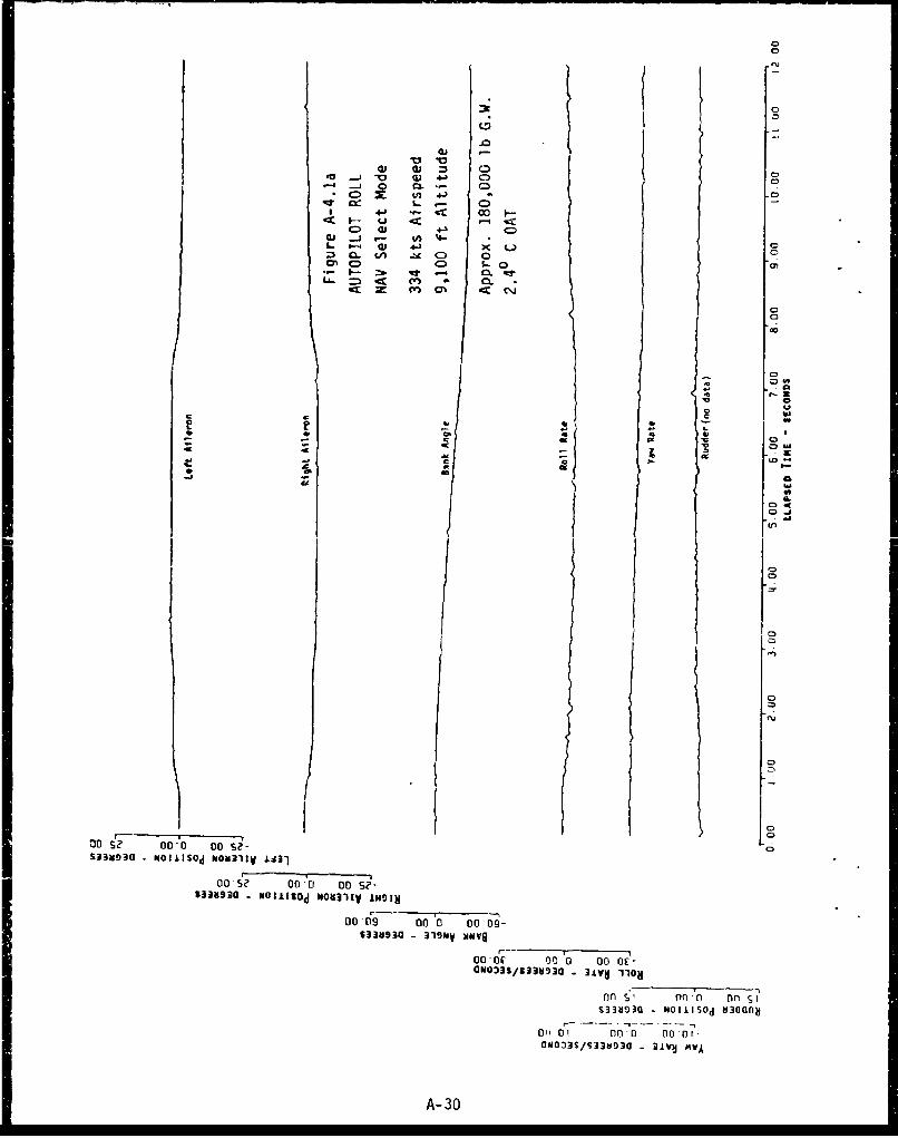
V0
-. 1 0 Q -. 0:.C=) X: o... 4 0 0
00 at~ 00-I-- .. j 4- '"
Z, Q. V/) -bd C3 0.- I- :* mr .4 0L
CE w m clC~,
CI
U4
0 S. . -. all
co 01 0 000-
co~~~U . .0 o 0
A- 30
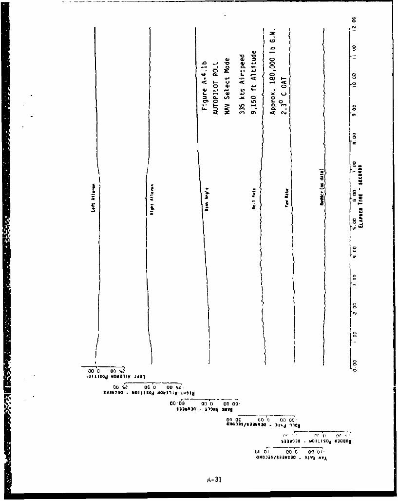
L. CD
S. - 41 41 x C= CL f/ -u C? 0
4m CD a.- S 0
= -CC 0nC
000 0 09 O A .10. (V*
00 *? 0.. '0 00"0111S4C XQJ-l (1
00 03 00 0 o 04233430 219mvllv0
ON M/3JSI - IOav
A- 31u

CD
0
0) ) 41 C
z j - C I-
Q 4.1 *u-4
CD. - V 4 -1
.m C- I-* t . .LL.. . CL m~ 0D
Lft
.00
C *CD
an up L3
-r r-
A-32

C.
C3
c c;.. 041 .- 0 Q4-
4) .4- C3LL 4A -V 0 0r
LL = 4< CL.~ ~ 41 ~ 4
= C. ~f .M 0.
40
fu
i? Do se
5blele NI~lod N311VAC.
DO se Oa 0 30 S
$131934 sio3
. . .......Do6 00 0 9V1m aov
10 010)0 0 1ago)ISI33990 -j IV F!A-33
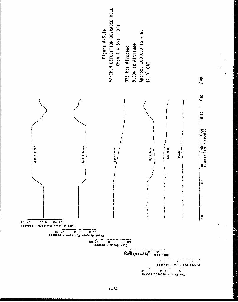
-LJm- 4
LLJV;C
= A:
4VG 4J C
4mLU CL C)4
i C4: 4. :LL LL-- C)
-cc 0cc4..
4-0
x0
INIC)
Cc WO
ni~~ p o ?
533V9300 alow oa
I- - --------
0%ass "0 -, 31a i
A- 34

Q:
UJI
Cl
IAJ
4A
>t .0C) V) Q)
tm S.- IIA C)~-i CL G .-W -l LL. L.t~
4.))
m <.
IL
C-11
Do 00 noS
on dc ni0 o f
0a0 000 00 0 0-
1301SS33w930 - NOIdAVd
A- 35
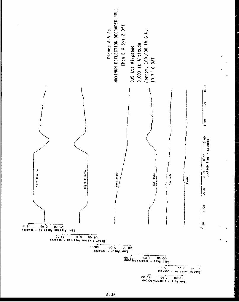
C)
LiJc~4-
40.0q) L) c)
0)' W a w - CS.. - a~ s-~~L&J ea ~
.- ...j 0 4 J
Lfl 4-
LAU C.)0
M - 0L CD
01
0 0-
00
C)
00 0 0-e"4'L s~ W 4' 11 -.~
_ _ _ _ _S3353 I l~ IIno Icf, n
Of,,. 01 ~ 00 lii 0007
S3gA - 36u ~v

C)
4-
L.J
C> 4n
*av .0) 3C
4)L G 4-) O
La.. ua. ca .- 0 I.- - .- cLL eo -r o
%A 4- *U
4-j
C I- D*o
/c f: 2L
oen C7%.~
000 000 000 00-S$336930m93 - N311sy 00011V'ai
002S~3g~ ? or) oot-s?
S339930 -319NVso XNaon
cc J 6c 000 '00C-1E
UNQO3JS/S33d!)a - 3V V
A-37

C)ox
Lin04-X.4-
to cr 4=
(nl 0 :
o IA0 ..1 C= (-) 4) .- (m. I-J ;I CL .41 C0~ .- 0i 4 .
0LjJ m 00 C)
Li 3 _r coo14-
= g .1.1 0 e
.0 CL r-.
CD
ow
00/ 00'
IJ13 NOI.~ NO 31V N11
00 09 co 0 o 06
S3393 N.J ~ U300
.4)3SS3a3 - 30d v
A-38
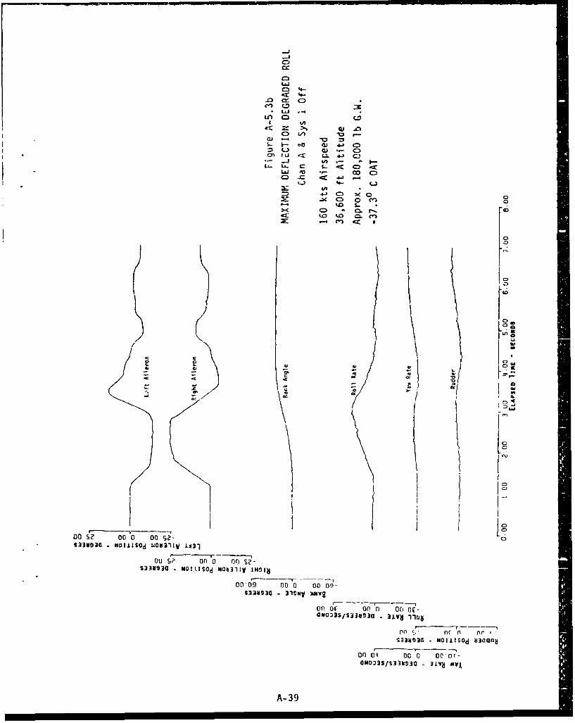
-J 4
-J -
4AO
o3 Li /C
LL - c0 'J4 C)
C) LJC CC 41 C.)
C) -0 m~4
4,. CO (OOD.)e C3.o
00 > r
'.0 o. 0
~~ I
K P
00 £? 0 00 Ose-
00i $? on 0 on) S-5338830 MO!.kIs0d N0b31IyV IH~ib
00 09 00 0 0o 09-S33ugao 31ONV )GNV8
orOfor , an 0 oc-
- r n----
S33403C NOIIISOd b3(10fnl
on) I 00 0 000of-aNDOI]S/S338930 -. 3±VU xvA
A- 39

-AJ
-J
.fl LL 03 064JC
4- C:.) OJ 0
.- j n -. IM .U%0 U.. CL ell Go
tnn
~ a,Ch0
2' 0
a, -- - -- -- --------
-k93 N-ilO NO3C IN'
00 09 00 a 0
or, dc 000 00 no0-
S33~S3SO3 -. II~ liliSa Many S3
or)? 000
Do 00?
'2Id03SSIS3393Q - 3LVN 11OA
A-40

-j-j
LO.
o) (A .
. i 4A - . I,L6. LA. Q s- <( a) zU.- 0
4j C0 0.
lk~o %0 L
I 10
CC
m
00
DOS se 00 00 Se'-
-3N3 *0111sOd NIi131Iy '"91 N
0')or)0 0 00 0 -ON033S/6331193C -3vg1o
ni n ', fir, c'S33as030 - hILIcod 830AHn
nor 0i 00 0 00,01-ONo33S/S33V934 314~ MVA
A- 41

cc
cr) 4- J C 0(.) OJi * CL-- C
&.. LiI1 O -4&- kfl 4-)- 1 L .- 40 - - 0~
tu 4-
-D 1-
0ý <0. a:
no~C or-0On.633U~a NIIISd N0311VINO0
00 09 OC. 0 on n
633U9a 319V xFv
A-42J

tm i 00.0 1
* 4-
LC) S- DQ 0L~r CL '4 ql 1
~~~C La C I.
0 07
00
(0
ID
on Sý '00 00 S,- IS33" 0 - OILS~d 104-11VIJUDo0 [ c e
waillod MN311VI~4i
00 C9 CC. 0 00 00
633US0 319v ANY
$3bl - N 'V~ aan
DOS?~0 00 05?
GN0J3S/S33a93O -1V 3Lvg 1
A-43

CD
coi
toQ 00 1KC 1-- 41 :3 C:0GJ LAJ. 3 Q.* .-L. *-j 4Ai , -JM LA. CM I- - c(M LAJ -- *.- <~ c0 1--
". cr trLA. .4-) C)
4.) S.. 0
C3J ( . CLc~i 0.
II
CO,
0 C; on n S
on1 09 o
0o Or0 0 ý
S33b'.?3C -NOiJISOd SIGUnfl
Onr, DO rj on n,GNOi3S/S33bjT930 31WH AVA
A- 44

C)
LA~. 4J C)
0 *) 4 l 0 iC
afl'4a4.i )( D
10
on 00"o 0 0 00
S383 N-;sc M03I0 N 1
_ _ _ '1 0 o 1
S33~30 NOLIS0d S/S3389ii3
00 ~? O fA-45

C)
cx
%D 9-3 C -
I. - eo -e m
t- W -- C0)-
43U +-) 0ý . C.JL. _j ~4- ý -
SLA- a) S- < C:)LL -1 00 c)o
IL 4-3 (D-30C
e.. j * Z
/ jj'LU0
C0' 09- 0 r .) - o
fi i: (If) n
SJ3OO)S/33O3 - IOIISý AOvAyJ-3
A-.46 03ssl3;:8io

C:)
CCD
4M) LL 4- 4-J CD
LL- (1 s- <C)
ol L. __j 00 C>O)LI .J 4u- 0-0
LI.. 4-
4-' C0-ý. 0) 0 00
>< ~ 0W . CL000 C) ac\J
/j m
.0
Lo
I a"LUor" l~l 010 o S7
S33b30 NIIISd N~~llVIS.
I- - - ----r); Kc D f c
S33S3b93 .OII~ d3GJS~ O~1Ir'd
on nn ri on nf
aNO23S/S?38930 -1V MVAj*1O
A-47

C,r-J
cni
(L) i- wco LLJ CL. 41~ 0
SLA- -r- S- C, <0) L'J 0)M *, coC
U- Ci 4- (.
4-jM: 0ý 00
0-' ~ a)C Q 1
In a
? XV
C 0D
K w5w
$33493 NOW ISOd W'11 IJ3
00 52 00 0 00IS2-
00*09 00 0 0 0 nO9-
S3 3V3 1SNV umNvS
0o0) de 0D 0 000E-UN033S/S33bD3c - 31VHf 1104
(~~fl ~ fl (iC P
-383 NOMISOd 80(oflb
or) 01 00O 00 01-
ON033S/SMH930 - 3lvNJM
A- 48~ ~ tafl'afl..a s a=S ..

C)
03
a) ~ ~ O .0 L 4- :
L. - 4 - . k-= U - .0 *.- 0)
GJ LiJ C"0 :
0 ' 4- C-La.n
4-) CD X 0 0
m Cr0 -
0 ~C~0
C,
2[
C,
10
00 S? w hr 0 ?
S383 -o"~ N031 =I
co 69 OD 0 of0(
MUON NCIISISNO UIQ1nd
o0 r', ofr 0 O)
ONG)3S/S338930 - 1" AV
A-49Pf

LL..oL 0
7D. (a. 4-W in
0j 00 % ;-
12 c f 00 C)i
w 4- C -3M ~ cL.J 4- C
*0 S- 0
4,J M --
- C 0 0a 4
CD'0
0(J
0L
00 To 000 s01
000 000 0001-0 21S3O3S/l9N83 - NOM'd NOU11OI9
93H3 --1NVr--V
si33HO30 NOIIISOd aIvuayofl b~lN3)
00"; onI 00sON033S/S338930 3JVH MAV
A- 50

LL.
oi 4 -J
Cp 0 a)4- C
ax 0.4 .0 tn .. I-j %- L C) <
0) CI . 0 C.)
01 LU '4- OA~* . L c 0 )j 4 C :)LA. CD .. j C 0 0 %0
C13O' C CL C)0 - CL.
Do
0
01
a0'93 - --S~ O31Vi~
00 C. 000 00S
63UI - 31m A-
ON 33 IS 3V 3 -, 31 H 10
oo oil0 06'0.
S33803a N4-J~ mban 813
00 s 000 00 SK136/aa 12b VA-51

Lj-LL-
I .Ne
*C) C-0) )
CL~ .- ,- CD.~ LaI 0f 4-)
0) CIO 'e 4cc 00
C~L. 4-
La. -D ~ eC 0-J S- C)
C:) '. 0. C
C) .~C)
IC-
0
0 .5 00 oo OJ
S303 -. 4.'V N
000 00, 00 -
A-52

LjL.Li-
cli -j uM - J a
CD 0 4) z 0>m- -j (1) 4-' C.3
. L~J .0 n.- -
w) in I- *-~ 00 -:3 41
a. Q) 4J x C) 0
CD 000
C:,
C) U
& 4
C)
00 u on Su 00
S33N930 NOIJISOd NON311V 1131
on S" 00 0 on Sý-S33SOA - NOlilsOd 1iON311V iw~lIý
o l 00 11 co sl
SM930~ - 319MV XNVq
00 01 oca 0 c 01-
ON033S/S330030 - 31.VN 110H
00 of- or 0 00 V.S33~1o3a NOIAISOd i±Navflo b31N3j
Cos Co00 00"'-GNOM3/S3M930 - 31VU AV
A- 53

C-
C:)
s- cx .00C71 LJ 4 S )
.- (100 4r-CD S- jl- 0
C) -
CD z
0~LU 4~ (fl 4
L4O
C.CD~-c~J~ T~crc
S3393 - NKISd MU1VI3
40 F 00 0 0
S3 aU -N-II~ NInlViHI
r-J
'I03S93V3 31 3NW 3 A V
A-54
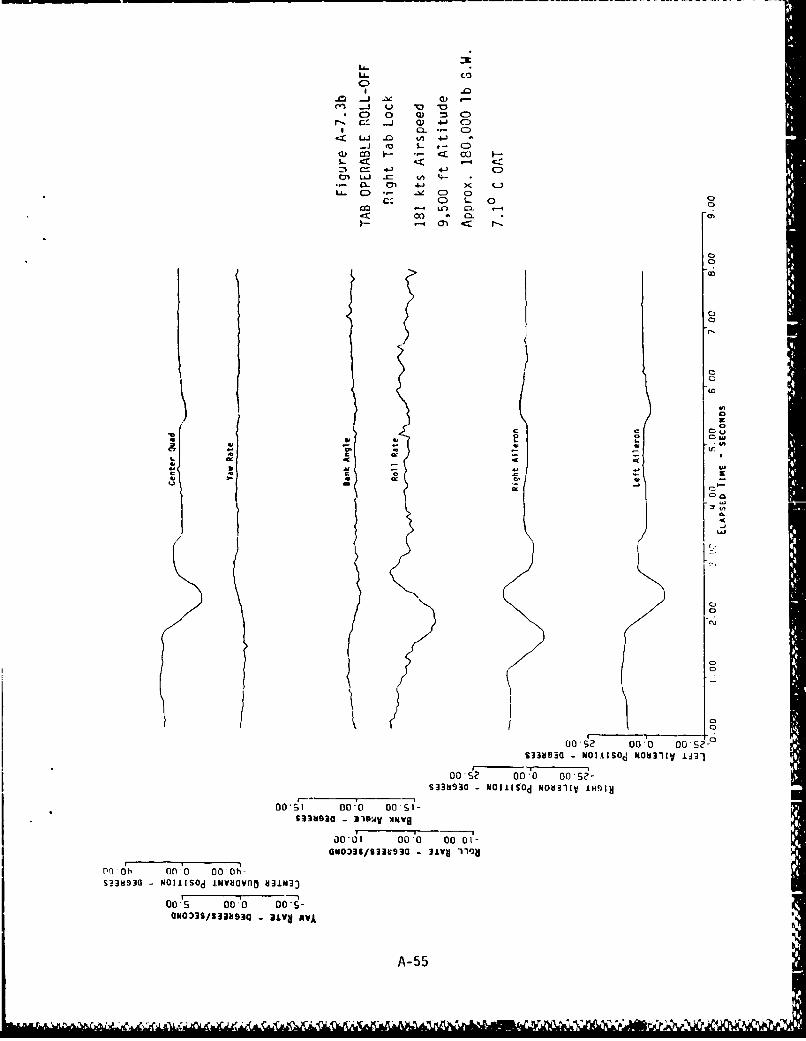
LL C
0S .-
.0
U! C:j -- J
00
~ LiJ .0.~w L -
Oc2) ODto 00 si
LL393 0 aiw -Nu 0
30-6 00 00 01-oON030/63NS3 - 3" 10H
nl)~ db *f' 0 ý
S?383G NIII~d mmo V1M0
00's 00.0 Do*
(IN03S/531193 jC)
A-55
ILC

C))
-j 0 -0 =I4~CD~ 'I, C3
~ 'In 4-' 0'cr LU tnl - I-
-j $~ .- < C L0(iCOJ CU .i - 00C ) 0
:3 4- (..J
.- Cl 4.- J-ý : X0) LL. 0) a) CD0 0
__j LO-
.c ~ C) CL0
cFi e~ (j < I
C30
Q
0
00 000 o
S383 - alN -AW
00 C, 00 -Kr.ý
A-5-

030
*0 0 -j -W C)C e
,..Cl Ij ~
.j *u
00 0-0 0I 0 0
o(L. V- 00 0 00 ý
S339. 0 319N -X C'c
0k ot, Go oS33Via 01110d ivv~nb vim0
00 'S co'J 00. I C
Cm3xv~ .4, AV
A-57
dLCU ~ ~ ~ 4 4. -- AU A R'~dAl A ý

LL- (
to -j a- -
a) C )4-
a) co 1-- 00 4
0~LJ- ~ 4-) C)LL Lý _b C 0 r-
cc. C~4) 0D ~CLVi.0*- .~i 040N
C)C)
kS
CL
.4.
00Ce 0 0, 00 's-:S3b3G-N1isd 031VL3
L0 0001 0M.S 000 00?-
MUM3~3 - NO111S~d iNO1Ivo 1131N3
or) s~ 000 0 D-$aSo)2/S3mq0 vivos~ N031V J4
00 S 000 00 A-5

C) .-. w .0CZ.- x. (. D CD1~ ~-0 *V 4- C
6- ~ ~ 0 CE 4) d 04) -
CL .- 0. C) oA-J C=) m -I C 0 C- C
,K S.- Co1D - in M.
Ci- C C)- C O) r "c i~ -j- I
0 - 0.Do C 0.C*..
I- e~eb
-C _
00ý --- -6 -I?+
00 ý2 000 0S3N3 - NOII~ NU,11 IH
0N 1000000
GOIAIS/S3V3 31V #%VA S3~3~Ii~I ~ ~)0 NIIo
COSI C A-5C

z 0ý
4I- CL C)14. Ch 4-)0ý & - 01-
ICD 4.) 4< -(dl - th 4--.
0) - 4.JL: CL 0. - 0 00
C~4) CD S- 0.m- ' CL CD
L.- CC CV -00 <
0
( 0n
'E.
ZE0
CL ex
r: -0n 0r (" (,0 o
S33331dSO - -ONlISId d N3bIV V IJII---- -------
00 2 000 0.09-SI3~S3833 -O.IS' LNVlJOVAO NfldIJV JH
0Of. S 00009
S~M3G-NOLS33d3 -N~~l NDLfL'dh flunoidMdSW
A- 60

(3
-c 0 -
c-o 00
W 4.) 0
4- 1
aI C:Lý Lr j U)Ci C 4C
-CC
00. 0 0r 00o
no n, o Of
00i s-c o4A9 ( -Nais d i a n o i d I S W
on1 0 on
A- 61
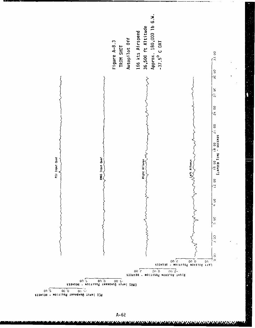
4a .0
d) 4-) 0D
(4- CL 4J Ce) 4- 0A . -
0D S.- 0 -C ) ;
00 4-- u
a,4-' 0) >4OL 04 CD 0 LO
S- 0 fl) L.IM 4-J %D0 A C. rý
ILj 4C -4 Cr) CC
Ii~0C)0
6CL C -
00 ?, of) 0 0
S3H3 N.CSdIV~veIdISW
on~ oo~ 0 orS33HSOM~3 -OII~ NOIIISwnd NO4d1I n
00A-62 n ?
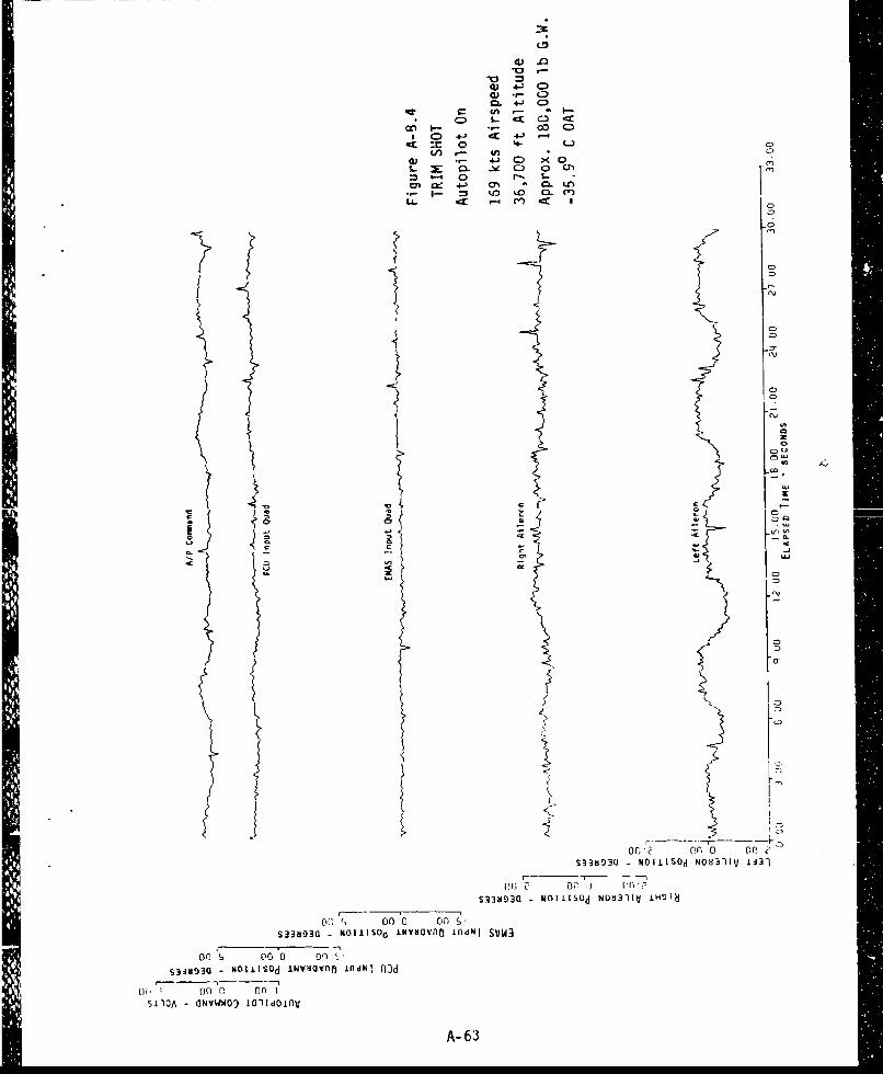
Q) 4-1 0D(1) C)-
I C0 4-J -C 4-) -4
4-3 CD X. 0 0
O' 4-) O * ca. LO
Li. tn LO- C' L c
0
0C)
0
so 3D3 K:ISdIvavoIdISW
A- 63

4) 4-j CD013 *.- 0ý
' uL~ 04< C)
cv. 4j-4 ~C)(cc '4-
a) CD 4J~ C) X(. Q: -V. CD 0 0
:3 L" LA L- M4m .4 LIM . 0
P-1 (Yn C) Ca ~LA CZ Cl J cl C
0
co
0
0
090
(0
-J3S~ -NI-SdNO I ~l
Do ~~~ .uu 009QN0333/S33bS3 31- V
OG 0? 0(! an .7
GN033S/S33aHg3O - 3LVWj IIOV 3~3 OlI~ O1~I
on 2' 00 0 00?
-NOlIV43331V 9NIA IHDIS
A- 64

Ln W
-1 S. Oc C
C% -=1 00- 0
0 - 49C ~ 4J -0 C
S- cr 44 ),- 0
Z LaJ Ll 5. 00)) . -. L .
LL. cc M~ C%j I
0l
CD
/ 'L
Do 2 00 a0,5 -
00 s o0 0 Do o 0Se"S3Sk3930 - NOIJ.ISdd"OO311V HO3N
ou* 000 00 D 00-?
9 - 0:i3S/3313 -NI i3 1 VO10
002 00.*0 CID(3-HtWOIIV3I33V VNIM 1H4I14
A- 65

a) 4J QW) *- CD
SQ" CD 41 CD
LLL)
z uj
0)0 a 00-0 0'90
00 0 00 0 0
Da O FL0o 0,1
** A LA C

W ) .-
-0 LJJ x) 4- CD
ON :3 00 0* 4Xt. 4-) .- 4
,- Or -e C 0 0=5 LUJ U-) $-
o~-j o *c In. %DýLt C') CL.
C,0
(0
tf .[U, 0
00 S? Do 0' 00
CI 00c
Of) S? fil 00o
S3318313G) -NI 11191dN031V A
A-67 fiU 009

) 03 - . i-
-o coC:Cl - 4-'
cU L.J o 4 -i c(U C> C ) -S-T ix (D 0C)
'A 4 S- C4
z z
S30 00- 0 DOCc
00 1. 00 0J 0o S?
Do -'Q .:j 0 00 (\QNA /3NI 31Vd MVA
Do 6? Do 'D 00 02
0 0
0Moliv -133) swi-4-91
A-6800 J ;'

0.3 4-) C)4) e-C)
£m L&J &A.4). f sii % - I- C
1 0- -T +-) .- 4t4 -
C)0 4-' CD Xm O -V C) 0 co
:3 LiI (\J I-
-d- ~ - C) 0L "\~C ' -,; cr
fC
02 0 00.csS33bjo O IIS~dN08311V .H31
S383l-NOIiIs~d N~b31lV 1IH918
ON0OD3S/S3~3b93a ~V
00o~ 00 0D 10 ?
00*? 00,0 oo~e-9 -NO~V&3I3)y9NIAq jj
pn 00 0 o00e-NoII±Vb3I3)y 9NIN INSIIN
A-9(A-70 blank)

APPENDIX B
BASELINEt DATA

I&c
B-1
• , .• i lI I II I

'4.it
r--'I,0
4B-

J %.-~X --- a-- x
'a--
-OV!i -111
-B-
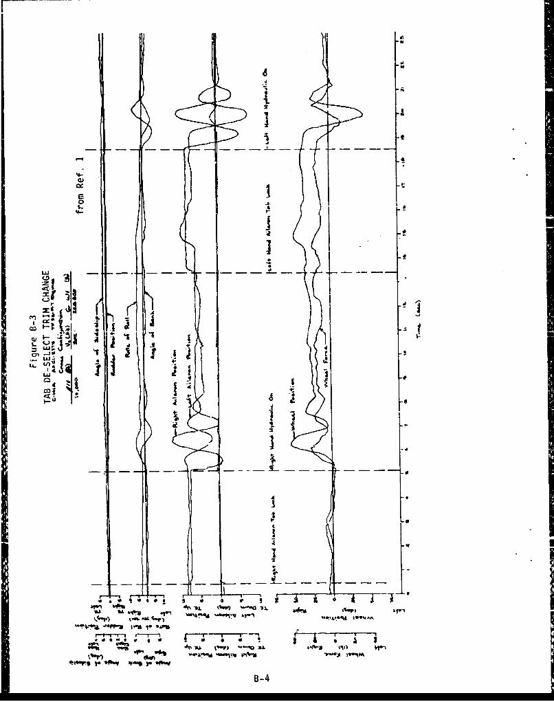
LLIi
iziCIO
L4-
I U- t
%A IL
d5 I
ot" -v 7-. -" 1 1-0-3,.%, OIt IM Iwv4*-ws soa -j B-4

C0.4
1-- -7 T- - - -I - -
r T~
vit- I -.
3~AA 'A.L
u-o "tj
__oI
B- ( -6 bl nk

APPENDIX C
ADDITIONAL TEST DATA

-J-
LL L r C)
aI V ) Q 4-) 0
a .. > %..L-. LLi 4) .- I- c= m -i di 4 _7
.- 2 E u '4Li. x C 4-
LLu. S-a2 0 . ILo0..<V~~I
m 3tIC
0
I.
GOf)? r no nil~S~33930 -NOI~ISOd NON311V 1:31
or SýZ Tr p I"
S33SD30 - NOIIISOd NOb3liV IH018
or'. r i c ý0NO033S/S338930 31Vd MAA
L', II CI C. uC Of, DE - Do 0t-GNOý3S/S33030 -31VH I1ON
WE.* 00 1 (00I 00 E-C)-NOli~b3l33V 9NIM 1331
00 E 00 I 00 I- 00 C--NOlI'V613:)3 VNIpj lh,!II
C-1
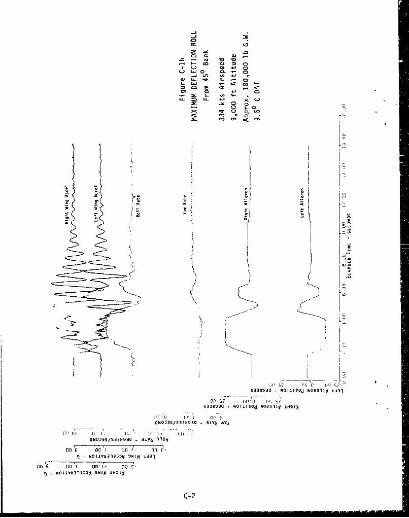
-Jc
o o -0 -
-4I-- co 'J CDC-) Q) C:)
C-) LiJO 0 *,- 0-j LA) 4f 4J)
w) Lj- di L - 0D1- LUJ . < CO'=3C E 4< r-
C" 0 41 C,*.- : S.. U) 4--
-L o.- 4- X C-
C, C) 0
r/ I
ChC
S3333b!33 N-il~ 'W0 11 50 d IJ31V II1
qr (1 00 (4ON003S/S338030 31W" AV&,
C0N)3S/S~393bV3 31Vb 110)M
On E 00 00 on On9-NOIIVU313ýDV ONIM IJ31
00 £ 00 1 00'1- 00 V-9-NUI1IVU13:))V SNIP 1H91d
C- 2

C)
~ 4S)
(D I- > -
L u GL') ." OC co I.-~ c *~ ~ -4 -c
~- ~ u~ 4-3LA- *~ -0 0
'm -e m- ej
-0 La
I a.
/ .-
.0
S
fr or' In 1 nS333SS33sa -iv NdJSm vi3jVi
on c 0 1 n I -00
NOIUNOS/3li:iOO ONI IIi9
1~~~--~ - C- 3

C)
-J L
=~ m D < 4 . (Z
oh - 4-
CJ E +j C3.) x0 (..9 0 00 0
;'...J 4-V C) CL ) '
U..~~ < 4J
~ 0 .~ 0 0
am, _ogo z
2CV
S33MG ~ ~ ~ ~ ~ u wolsdNU-l L:3
on. S? r t I.
Mu3 0OLSdN831 NI
of. C cio
GNOA /S33193 31v A0
Orfl t) oF rl f ý [
NOIIIJ33D) -I~j NOII:01t31~LH-------- --------
oo 00 1 00) I oo 00 F-
- tOli~t3l333V DPIM INDIý
C- 4

;r_ ca 0 .0
C', - C: (1) 4.) C)
_j~ knsu &- cc C;
LLL > OD Co-J> c* Q)* 4- r-4 C
LL .4-3 C)
q- S. Kým ~ C'J C3. ,
II I
000
ml- 0; 10 -i
C-5I

-4-U. 4 ,
co 0U Cý
4,m LII L . .e)
v~~~0 L
4- .
c~C)
LALo
S33b930 N01SdN8-1 H 1
-0 *.C 00 '10.1- 0
00 E 0 1 0 1- 0
C-6~

C)
to :3r_~ Q) - -o C
u (a 4V O .- 0DL.) LU co CO 4-) CD
0.1 LL. 0 1-S-LW 4l-J co C)
:3I I cr 4J ý
.- ~ C tn 4- )
La. =D (a 4~1 C) > 0 cr.X:c ,.~ D o 00r-
cc L. %0 OL-
Of G
00>
.o~ U -1)) CAJH I
C-7 (C- blank
APPENDIX D
ACTUATOR TECHNICAL DATA
-- - - - -

COMPARISON OF EMAS AND HYDRAULIC PCU
EMAS PCU
Maximum Output Force 19,050 lbs 19,050 lbs
No Load Rate 4.65 in/sec 4.65 in/sec
Stroke * +3.35 in, -2.08 in +3.35 in, -2.08 in
Frequency Response 4Hz (1st order) 4Hz (1st order)
Maximum Freeplay 0.018 in 0.095 in(approx. 0.13 deg)
Weight 65 lbs 58 lbs
Reliability 448,632 hrs 115,004 hrs
Stiffness 6.0 x 10⁵ lb/in 5.6 x 10⁵ lb/in
" full riechaniLal st.rok.e, actual s.,ro.e for ......... ailerondeflection less
Additional EMAS Information
Motor No Load Speed - 9,600 rpm
Maxitaum Power Required - 8,000 Watts at 115 VAC
Reliability - 4,000 cycles to single channel failure5,000,000 cycles to dual channel failure
Limit Load - 23,300 lbs
Ultimate Load - 35,000 lbs
power-off backdrive at 0.12 in/se' with less than 360 lbs
(all information from contractor estimated or laboratory test data)
D-I (D-2 blank)

DISTRIBUTION LIST
4950 TESTW/FFDS - 15 copiesWright-Patterson AFB, OH 45433-6513
4950 TESTW/DOMP - I copyWright-Patterson AFB, OH 45433-6513
AFWAL/FIGLA - 3 copiesWright-Patterson AFS, OH 45433-6523
AFWAL/GLIS - 1 copyWright-Patterson AFB, OH 45433-6523
WRALC/MMSRD - 1 copyWarner-Robbins AFb, GA 31092
HQ AFSC/TE - 1 copyAndrews AFB, MD 20334
Air University Library - 1 copyMaxwell AFB, MD 20334
Defense Technical Information Center - 12 copiesDTIC-DDACAlexandria, VA 22304-6145
Lockheed-Georgia Co - 3 copiesMarietta, GA 30063
Sundstrand Aviation Mechanical - 2 copiesRockford, IL 61101
* (;PO Cp 646-067*


![IC Test Report - Amazon Web Services · Summary of Test Results IC Rules Test Items Measured Result RSS-Gen Section 8.8 Conducted Emissions [dBuV]: 4.646MHz 48.88 (Margin -7.12dB)](https://static.fdocuments.net/doc/165x107/5e5e5a985fd4a2673d46d4f6/ic-test-report-amazon-web-services-summary-of-test-results-ic-rules-test-items.jpg)