D-STAR D-STAR Repeater Basics Icom America Inc. TSR.
110
D-STAR D-STAR Repeater Basics Icom America Inc. TSR
-
Upload
alan-miller -
Category
Documents
-
view
223 -
download
1
Transcript of D-STAR D-STAR Repeater Basics Icom America Inc. TSR.

D-STAR
D-STAR Repeater Basics
Icom America Inc.
TSR

TSR
What is D-STAR?
D-STAR: Digital Smart Technology for Amateur Radio
Open protocol, published by the JARL (Japanese Amateur Radio League).
Available to be implemented by anyone.
Digital voice (DV) and Digital Data (DD) operation.
Currently, Icom is the first and only radio manufacturer selling D-STAR radios in the USA.
http://www.arrl.org/FandES/field/regulations/techchar/

TSR
What is D-STAR?
Icom D-STAR Digital Voice and Digital Data rates.
144 and 440 MHz data rate – 4800 bps
Digital voice @ 3600 bps (including error correction)
Digital data @ 1200 bps
1.2 GHz Data rate – 128 kbps
High speed data @ 128 kbps (Ethernet connection)
or
Digital voice @ 3600 bps (including error correction)
Digital data @ 1200 bps

TSR
What’s required?
Repeater Call Sign
First, you need is a unique / club call for the repeater.
* You can not have the same call sign in 2 different “roles” in the D-STAR network. (eg, the repeater call sign can not also be your individual call sign.) You will need a unique / club call sign for your repeater system that is not used anywhere else in the network.

TSR
What’s required?
Repeater Components
Next, you need the desired repeater modules. The RP2C is REQUIRED for the D-STAR repeater system.
The current D-STAR repeater modules are:RP2D 1.2GHz, 128K Digital Data (DD)RP2V 1.2GHz Digital Voice (DV)RP4000V 440MHz Digital Voice (DV)RP2000V 144MHz Digital Voice (DV)

TSR
What’s required?
Additional hardware
Each physical install is different. What your install requires may vary.
Examples of additional equipment:DuplexersPower SupplyAntennasWindow Filter
D-STAR
RP2C Controller
Icom America Inc.
TSR
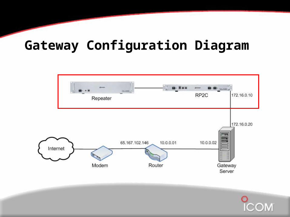
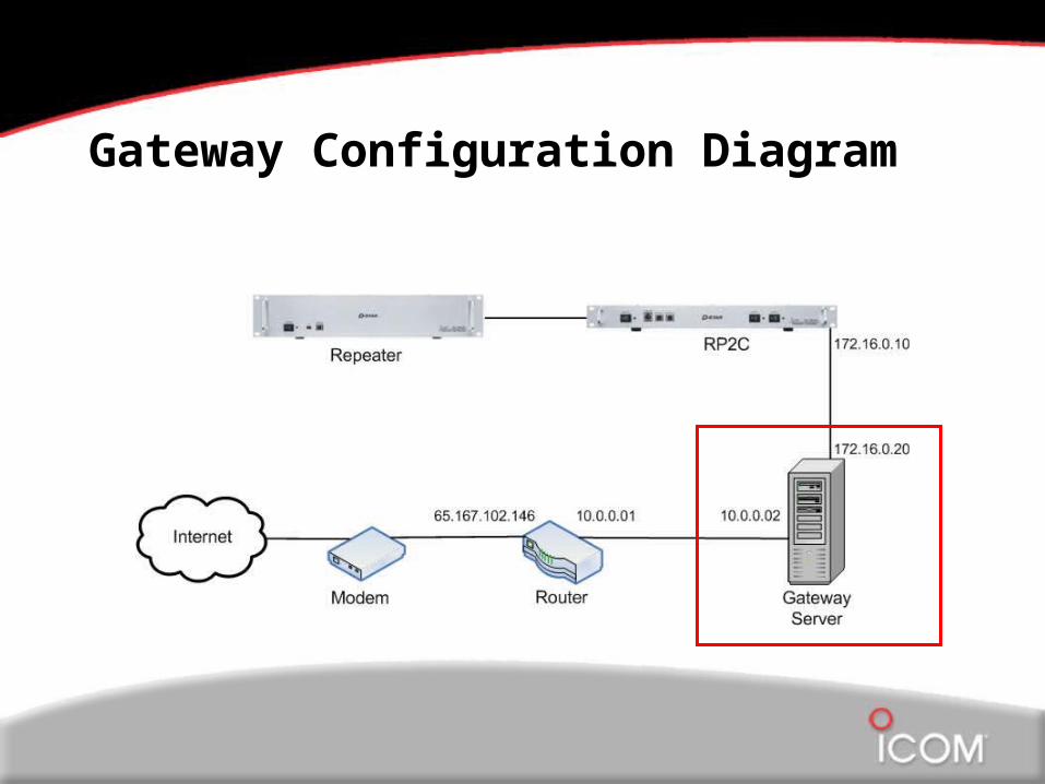
Gateway Configuration Diagram

TSR
What’s required?
Programming PC (Windows)
To program the repeater controller and frequencies you need:
Windows based PC with at least 1 Ethernet and 1 USB portUSB A to B cableEthernet cable (not crossover)
Install the included software on the Windows PC for: ID-RP2C ID-RP2VD ID-PR2000V ID-RP4000V

What’s required?
Before programming you must know the IP address of your RP2C controller.
Default: 172.16.0.1
Recommended: 172.16.0.10

TSR
RP2C controller
The controller is programmed via the Ethernet port on the front.

TSR
RP2C controller
We must configure the PC to the same IP scheme as the controller to program.
TSR
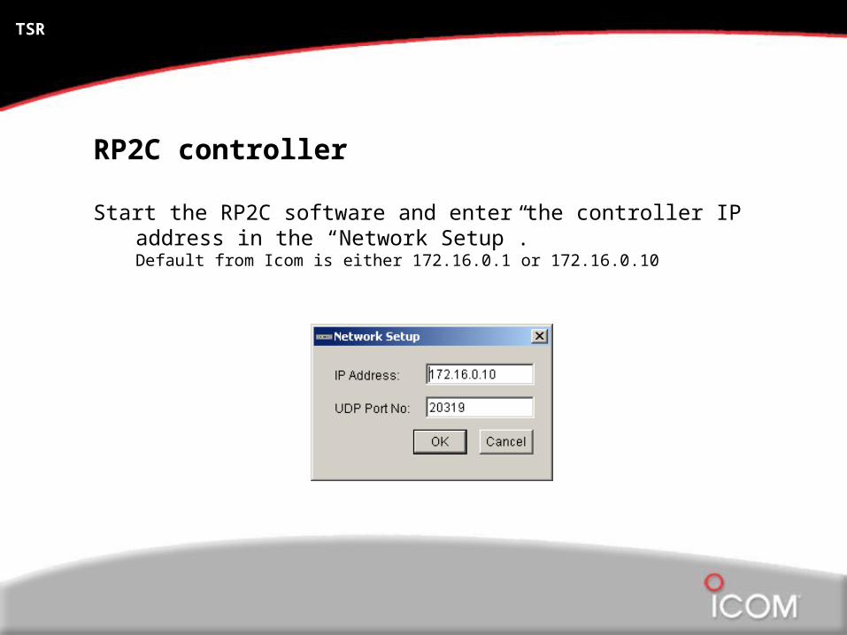
RP2C controller
Start the RP2C software and enter the controller IP address in the “Network Setup”.Default from Icom is either 172.16.0.1 or 172.16.0.10

TSR
RP2C controller
Click the “Read” button and enter the password.
(PASSWORD, all in caps, is the default password.)

TSR
RP2C controller
Now, you should see something like this

TSR
RP2C controller
Enter the repeater call sign

TSR
RP2C controller
Select the “module configuration” from the drop down menu.

TSR
RP2C controller
Select the “active ports”

TSR
RP2C controller
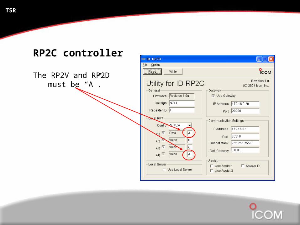
And assign the proper module letter designation.
Recommended designations:
RP2D (1.2 GHZ) ARP4000V (UHF) BRP2000V (VHF) C
TSR
RP2C controller
The RP2V and RP2D must be “A”.

TSR
RP2C controller
Select “Use Gateway” if connecting to a gateway PC.

TSR
RP2C controller
Click “Write” to save the settings to the controller

Repeater Module
The repeater modules are programmed via the USB ports on the front of the repeater. There is one port for TX and one port for RX.

Repeater Module

D-STAR
Router / Linux Configuration
Icom America Inc.
TSR

Gateway Configuration Diagram

TSR
What’s required?
Internet Connection (Fixed IP address)
The D-STAR gateway software REQUIRES a fixed IP address and, at least a DSL speed connection.
You will also need a router capable of:Class “A” internal subnet (LAN) 10.0.0.1 / 255.0.0.0Port forwardingSetting a fixed IP address, such as for PPPoE for WANRefer to the RS-RP2C manual for additional requirements.
(The Linksys WRV54G meets all the requirements)

TSR
What’s required?
Gateway server PC (Linux)
This is what we are here for, right?
Minimum PC requirements (per Icom)Linux OS (recommend Fedora Core 3 or 4)Pentium grade 2.4GHz or faster CPUAt least 512MB RAM2 LAN cards (NIC from Intel recommended)At least 10GB hard drive free space
**These instructions are based on a Linux Fedora Core 3 install.**

TSR
Router settings
Make sure your “local IP” settings are set as shown.

TSR
Router settings
You need to forward a few ports through the router.
Data sync: 20005TCP
Voice RX: 40000UDP
Data RX: 40001TCP

TSR
Router settings
You may also want to allow additional ports like:
SSH:

TSR
Gateway server configuration
Select “statically set IP”
Input the settings for eth0 as shown
Eth0 (LAN side)
Address: 10.0.0.2Subnet: 255.0.0.0Def Gateway: 10.0.0.1

TSR
Gateway server configuration
Select “static IP” for eth1 as well and enter the proper settings.
Eth1 (gateway / RP2C side)
Address: 172.16.0.20Subnet: 255.0.0.0Def Gateway: none
TSR
Gateway server configuration
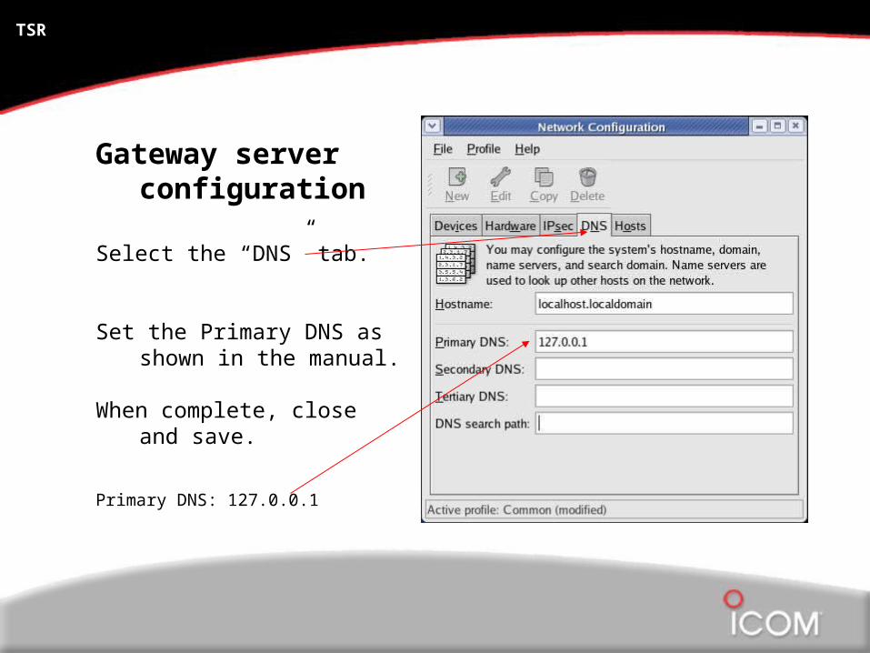
Select the “DNS” tab.
Set the Primary DNS as shown in the manual.
When complete, close and save.
Primary DNS: 127.0.0.1

TSR
Gateway server configuration
Add these lines to the named.conf with your favorite Linux text editor.
Syntax is VERY important here.

TSR
Gateway server configuration
Create a new folder “/var/dsipsvd”
This is where the software stores the backup files.

TSR
Gateway server configuration
Next, you need to create the “dstar.local.db” database file, once again using your favorite Linux text editor.
This file will reside at:/var/named/chroot/var/named/
dstar.local.db

TSR
Gateway server configuration
Syntax is VERY important in this file!

TSR
Gateway server configuration
After creating the dstar.local.db file, activate and re-start the “named” service.
Select and edit “runlevel 3” from the menu.

TSR
Gateway server configuration
In Runlevel 3, and Runlevel 5 click on “named” and then click “restart”
* An error in the “named” configuration is a common cause for the gateway to not operate properly.
TSR
Gateway server configuration
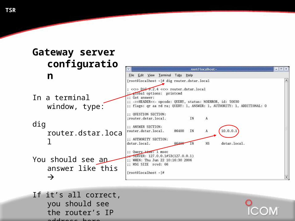
In a terminal window, type:
dig router.dstar.local
You should see an answer like this
If it’s all correct, you should see the router’s IP address here (10.0.0.1)

D-STAR
Gateway Software
Icom America Inc.
TSR
Gateway Configuration Diagram

TSR
What’s required?
D-STAR / Gateway software
Icom’s Gateway software is a licensed vendor product, and can not be copied, shared or re-distributed.
TSR
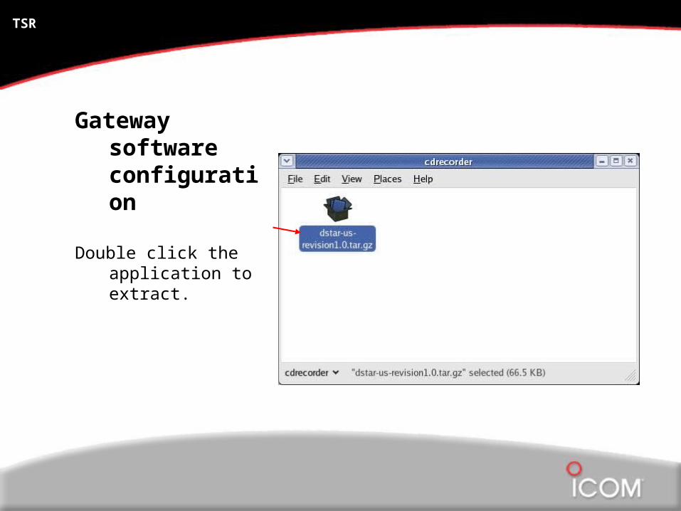
Gateway software configuration
Double click the application to extract.

TSR
Gateway software configuration
Make sure to extract the program to the “root” directory.
(A new folder will be created.)
DO NOT create a dstar directory.

TSR
Gateway software configuration
Edit the following in the dsipsvd.conf file:
TRUST_SERVER
ZR_CALLSIGN
IPSV_ADDR
DNS_ZONE_FILE_PATH
NAMED_PID_FILE
NOTE: The IP address of the Icom test system is 65.102.167.146
TSR
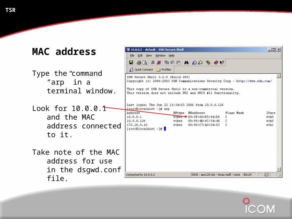
MAC address
Type the command “arp” in a terminal window.
Look for 10.0.0.1 and the MAC address connected to it.
Take note of the MAC address for use in the dsgwd.conf file.

TSR
Gateway software configuration
Edit the following in the dsgwd.conf file:
ZR_ADDR
ZR_CALLSIGN
DNS_MAC

TSR
Gateway software configuration
Add the lines here in the /etc/syslog.conf file:
# for D-STARlocal0.* /var/log/
dsgwd.loglocal2.* /var/log/
dsipsvd.log
Make sure to type this right. It’s “local” before the number.

TSR
Gateway software configuration
Now, let’s add the command line to start the software.
Insert the following in /etc/rc.d/rc.local
/dstar/exec-mgsv
NOTE: Some manuals are WRONG!

TSR
Gateway software configuration
Finally, change the default runlevel to “3”
Locate the file: /etc/inittab
Change the runlevel to “3” here.
D-STAR
Gateway Server Setup Verification
Icom America Inc.
TSR
TSR
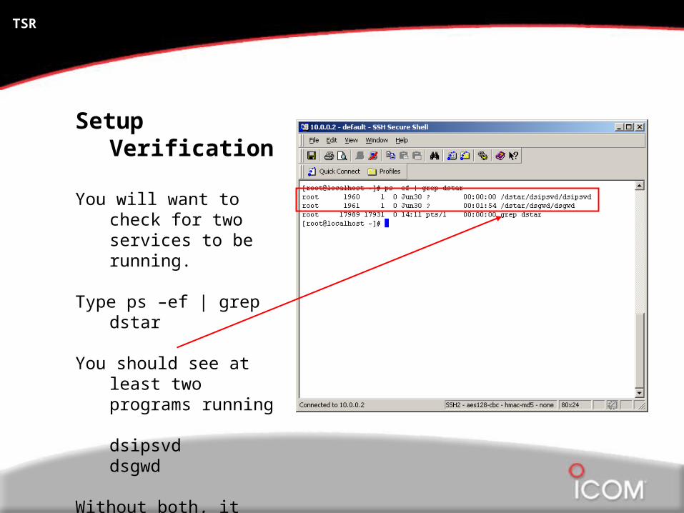
Setup Verification
You will want to check for two services to be running.
Type ps –ef | grep dstar
You should see at least two programs running
dsipsvddsgwd
Without both, it will not work!

TSR
Setup Verification
If the services are not running, we can check the log file at:
/var/log
Both logs are saved as:dsipsvd.logdsgwd.log

TSR
Setup Verification
The easiest way to see if it synchronized is to look at the dstar.local.db file.
You can use the GUI by typing “startx” on the command line, if desired.
Open the file:/var/named/chroot/var/named/
dstar.local.db

D-STAR
Adding Users
Icom America Inc.
TSR
TSR
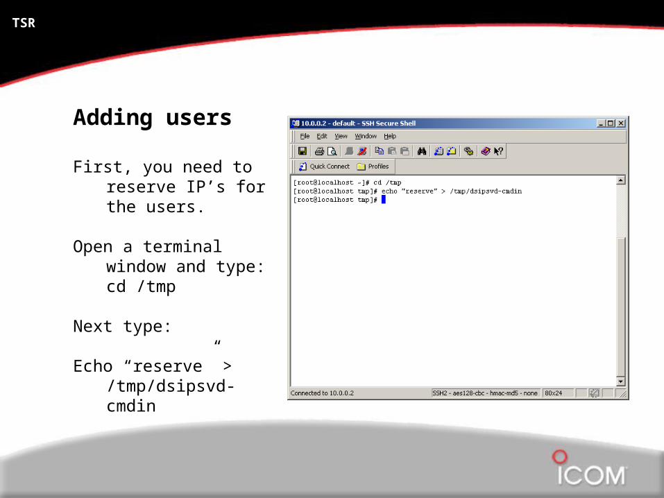
Adding users
First, you need to reserve IP’s for the users.
Open a terminal window and type: cd /tmp
Next type:
Echo “reserve” > /tmp/dsipsvd-cmdin

TSR
Adding users
To see the reserved IP’s, type:
cat /tmp/dsipsvd-cmdout
You should see results like this
IP’s are reserved in blocks of 32.
As the administrator, we recommend creating a log file to track these IP addresses.

TSR
Adding users
Now you can add the users.
You will add 1 call sign user per reserved IP (fixed IP address, 10.x.x.x).
The command line is shown in the guide.
Syntax is VERY important!

TSR
Adding Users
From the linux command line:
Change directories to tmp cd /tmp
The “add user”command format is:
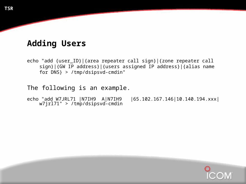
echo "add {user_ID}|{area repeater call sign}|{zone repeater call sign}|{GW IP address}|{users assigned IP address}|{alias name for DNS} > /tmp/dsipsvd-cmdin"
User ID is the users call sign it must be 8 characters. add spaces to the end

TSR
Adding Users
echo "add {user_ID}|{area repeater call sign}|{zone repeater call sign}|{GW IP address}|{users assigned IP address}|{alias name for DNS} > /tmp/dsipsvd-cmdin"
Area Repeater Call Sign is the system call sign with the letter [A] in the 8th position, use spaces between the call sign and the [A]
Zone Repeater Call Sign is the system call sign it must be 8 characters add spaces to the end
GW IP Address is the public address of the gateway system
Users Assigned IP Address is the address assigned to the user by the local address coordinator
Alias Name for DNS is the users call sign, in lower case, with no spaces at the end.
TSR
Adding Users
echo "add {user_ID}|{area repeater call sign}|{zone repeater call sign}|{GW IP address}|{users assigned IP address}|{alias name for DNS} > /tmp/dsipsvd-cmdin"
The following is an example.
echo "add W7JRL71 |N7IH9 A|N7IH9 |65.102.167.146|10.140.194.xxx|w7jrl71" > /tmp/dsipsvd-cmdin

TSR
Important Points!
Only users added to the gateway can cross the D-STAR gateway to access the network.
Once a user is added to the D-STAR gateway, they have gateway rights via any D-STAR gateway pointed to the same trust server.
Any user can operate locally on the repeater, with or without a call sign.

TSR
Adding users
Once all the users are added, type:
cat /tmp/dsipsvd-cmdout
You should see, per the number of entries:
200 Command OK

D-STAR
Checking GIP, RIP and MNG Tables
Icom America Inc.
TSR

TSR
Gateway server
The gateway software uses 3 tables:RIP – Reserved IP addressesGIP – Gateway IP addressesMNG – Call sign manage table
The backup tables are stored in the /var/dsipsvd folder
The “production” files are resident in memory, downloaded from the trust server. You can “write” the tables to a text file to view, if desired. You can not edit them direct because they are in memory.
All files are updated / merged automatically with the trust server and all the other gateways on the network at least once a day.
TSR
GIP (gateway IP), RIP (reserved IP) and MNG (call sign manage) tables.
All 3 “Live” tables are in memory and can not be directly edited.
All 3 tables store a backup in the /var/dsipsvd folder.
You must “write” the tables from memory in order to view the current files.

TSR
“Writing” tables
From a terminal window, type the command:
echo “write MNG /tmp/mng.txt” > /tmp/dsipsvd-cmdin
Replace “MNG” with “GIP” or “RIP”

TSR
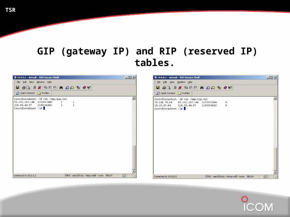
“Writing” tables
View the files you just created by typing:
cat /tmp/mng.txt
Replace “MNG” with “GIP” or “RIP”
TSR
GIP (gateway IP) and RIP (reserved IP) tables.

D-STAR
Testing and Going “Live”
Icom America Inc.
TSR

TSR
Testing and going “Live”
In order to go “live” on a D-STAR network, we recommend being 100% functional on the Icom test system first. Contact Icom D-STAR support team for testing at [email protected]
If you have ANY questions, contact Icom before you do something. We don’t want to corrupt the network and make it bad for all the other users.
Once operational on the “test” network, you need to “kill & clean” your gateway, change the TRUST_SERVER IP address, and re-boot your PC.
TSR
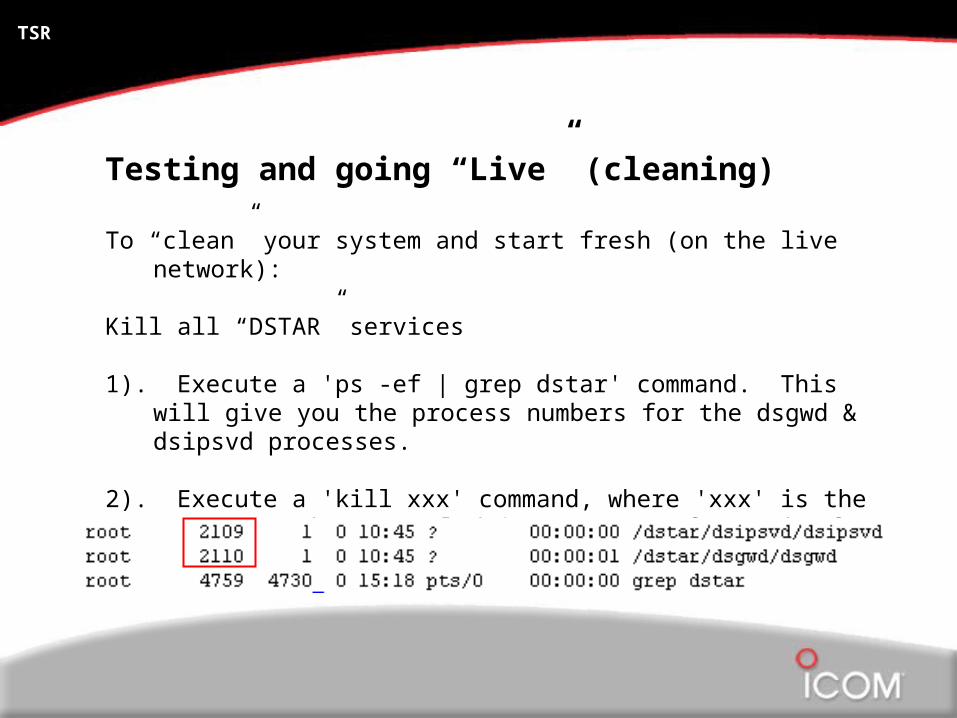
Testing and going “Live” (cleaning)
To “clean” your system and start fresh (on the live network):
Kill all “DSTAR” services
1). Execute a 'ps -ef | grep dstar' command. This will give you the process numbers for the dsgwd & dsipsvd processes.
2). Execute a 'kill xxx' command, where 'xxx' is the process number revealed in step one, for each of the two processes.

TSR
Testing and going “Live” (cleaning)
3). Execute a 'rm /var/dsipsvd/*.*' command. Verify the /var/dsipsvd directory is empty.
4). Edit the file /var/named/chroot/var/named/dstar.local.db with a text editor and delete any call sign entries after #DSTAR A RECORD.
5). Execute a 'cat /etc/dsipsvd.conf' command, and ensure that your TRUST_SERVER points to the proper server IP for the desired network xxx.xxx.xxx.xxx
Use a text editor, such as joe or the GUI interface to change the TRUST_SERVER IP, if needed.

TSR
Testing and going “Live” (cleaning)
6) Execute a ‘reboot’ command on your gateway.
7) The gateway will come up clean, and pull new files from the TRUST_SERVER, then re-synch with each of the other gateways.

TSR
TRUST_SERVER
A trust server, IARoot, is provided by Icom as a service to the D-STAR community.
There are other trust servers around the country such as USRoot provided by K5TIT in Dallas TX.
You can use your own private trust server to create your own D-STAR network or you can link to one of the other trust servers around the country, if desired.
Any PC running the gateway software can be set as a trust server to create your own private network.
The Gateway server MUST be located at the repeater. The 172.16.0.20 LAN segment (controller to gateway) is VERY sensitive to latency!

TSR
Important Points!
All gateways pointed to the same trust server share the same GIP, RIP and MNG tables.
These tables CAN NOT be changed or “cleaned-up” on your own. It requires all connected gateways to be “killed” and “cleaned” first.
Once all connected gateways are “killed”, the trust server files can be edited BEFORE any gateway is re-booted.
When the gateways are “cleaned” and re-booted, they will download the new GIP, RIP and MNG tables from the TRUST_SERVER.
D-STAR
D-STAR radios
Icom America Inc.
TSR

TSR
Icom ID-1
1.2GHz D-STAR amateur radio
Digital Voice, Digital Data and Analog Voice operation.
10 watt TX power.
PC control via USB or direct control via RC24 control head. USB Cable, software and RC24 control head all provided.
TSR
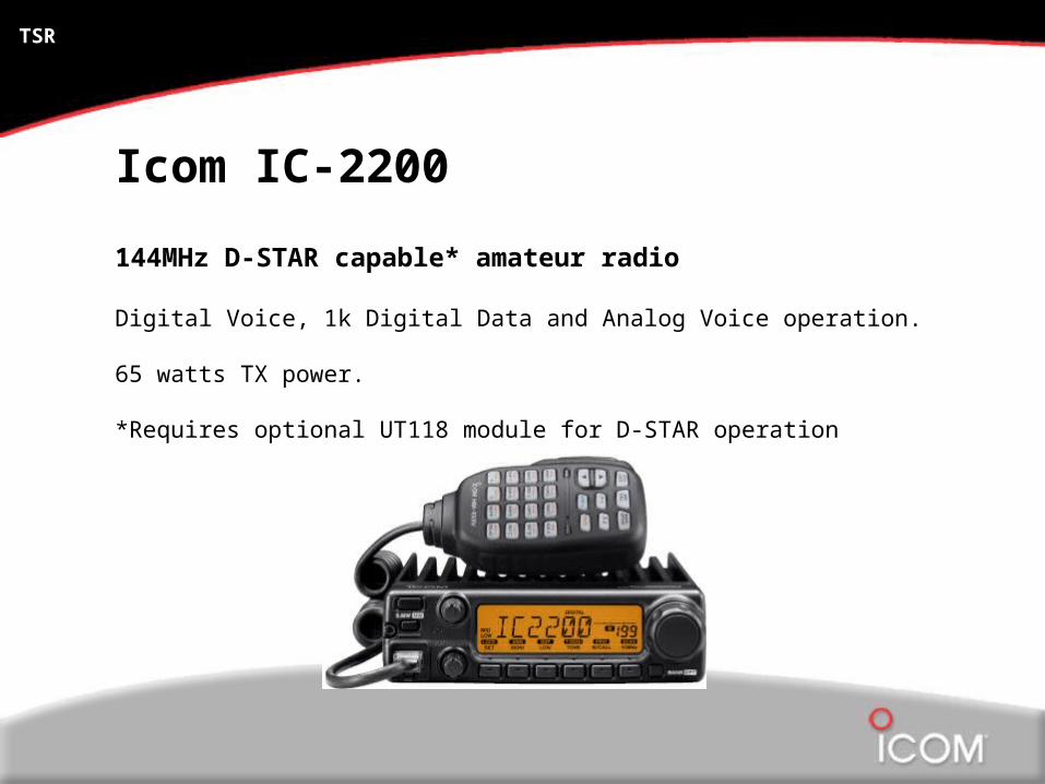
Icom IC-2200
144MHz D-STAR capable* amateur radio
Digital Voice, 1k Digital Data and Analog Voice operation.
65 watts TX power.
*Requires optional UT118 module for D-STAR operation

TSR
Icom ID-800
144 / 440MHz D-STAR dual band amateur radio
Digital Voice, 1k Digital Data and Analog Voice operation.
55 / 50 watt TX power.
Detachable control head, 1 band at a time. Same chassis as the IC-208.

TSR
Icom IC-V82 / U82
144 or 440MHz D-STAR capable* amateur radios (mono band)
Digital Voice, 1k Digital Data and Analog Voice operation.
7 / 5 watts TX power.
*Requires optional UT118 module for D-STAR operation

TSR
Icom IC-91AD
144 / 440MHz D-STAR amateur radio (dual band)
Digital Voice, 1k Digital Data and Analog Voice operation.
5 watts TX power.
True dual band / display operation.

D-STAR
How it works
Icom America Inc.
TSR

TSR
Understanding how it works
D-STAR utilizes call signs to “route” the radio call.
Every repeater must be assigned a unique call sign (club call recommended).
Every owner / operator programs their radio with their own call sign.
Call sign is transmitted digitally with each transmission.
No need to voice ID with D-STAR since digital ID is part of each TX.

TSR
Understanding how it works
Each radio has 4 call sign fields to be programmed. What you need to know to program a radio is:
Operating frequency Simplex or Duplex frequencyMyCall Your call sign (primary operator)UrCall Call sign of the person / zone being calledRpt1 1st repeaterRpt2 2nd repeater

TSR
Understanding how it works (Simplex)To complete a local simplex call, program 2 fields along with the
frequency in the radio.
MyCall My call sign (eg. W7JRL)UrCall Your call sign or “CQCQCQ”
MyCall - N9JA
UrCall – KD7DIQ
MyCall - W7JRL
UrCall – CQCQCQ
MyCall - KD7DIQ
UrCall – CQCQCQ

TSR
Understanding how it works (Simplex)In this example, all parties in digital mode hear all the traffic on the
simplex channel.
MyCall - N9JA
UrCall – KD7DIQ
MyCall - W7JRL
UrCall – CQCQCQ
MyCall - KD7DIQ
UrCall – CQCQCQ

TSR
Understanding how it works (Repeater)To complete a local zone repeater call, program 3 fields along with the
frequency in the radio.
MyCall My call sign (eg. W7JRL)UrCall Your call sign or “CQCQCQ”Rpt1 Local repeater call sign

TSR
Understanding how it works (Repeater)When you program your radio’s
“RP1” location, and the proper frequency, your radio tells the desired repeater to activate. This is similar to PL tones in analog.
Eg. MyCall W7JRLRPT1 N7IH AUrCall CQCQCQRPT2 nothing
N7IH Repeater

TSR
Understanding how it works (Repeater)Eg. MyCall W7JRL
RPT1 N7IH AUrCall CQCQCQRPT2 nothing
In this example, the N7IH repeater would activate on the repeater frequency you were transmitting on (1.2GHz).
(In this example, we are using the ID-1 radio.)
N7IH Repeater

TSR
Understanding how it works (Repeater)
All parties on the local repeater channel will hear all the local radio traffic on that frequency.
MyCall - N9JA
UrCall – CQCQCQ
Rpt1 – N7IH A
MyCall – W7JRL
UrCall – CQCQCQ
Rpt1 – N7IH A
Repeater – N7IH
TSR
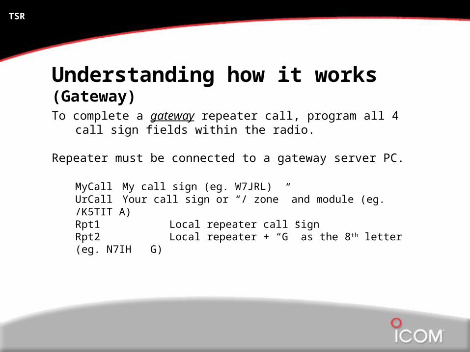
Understanding how it works (Gateway)To complete a gateway repeater call, program all 4 call sign fields within
the radio.
Repeater must be connected to a gateway server PC.
MyCall My call sign (eg. W7JRL)UrCall Your call sign or “/ zone” and module (eg. /K5TIT A)Rpt1 Local repeater call signRpt2 Local repeater + “G” as the 8th letter (eg. N7IH G)

TSR
Understanding how it works (Repeater)Eg. MyCall W7JRL
RPT1 N7IH AUrCall /K5TITRPT2 N7IH G
In this example, the N7IH repeater would activate on the repeater frequency you were transmitting (1.2GHz) and then…
(In this example, we are using the ID-1 radio.)
N7IH Repeater

TSR
Understanding how it works (Repeater)Eg. MyCall W7JRL
RPT1 N7IH AUrCall /K5TITRPT2 N7IH G
routed to the gateway and directed to the proper remote repeater through the internet.
N7IH Repeater

TSR
Understanding how it works (Repeater)Eg. MyCall W7JRL
RPT1 N7IH AUrCall /K5TITRPT2 N7IH G
The gateway is told where to route the call based on what is in the “UrCall” field of the radio.
/K5TIT tells the gateway to route the call to the K5TIT repeater. The “/” means “zone call”.
N7IH Repeater

TSR
Understanding how it works (Gateway)
Using “/” in front of the repeater call sign in the “UrCall” field activates that “zone” (module) at the remote repeater.
MyCall – W7JRL
UrCall – /K5TIT
Rpt1 – N7IH
Rpt2 – N7IH G
Repeater – N7IH Repeater – K5TIT
MyCall - N9JA
UrCall – /N7IH
Rpt1 – K5TIT
Rpt2 – K5TIT G
Gateway / Internet
TSR
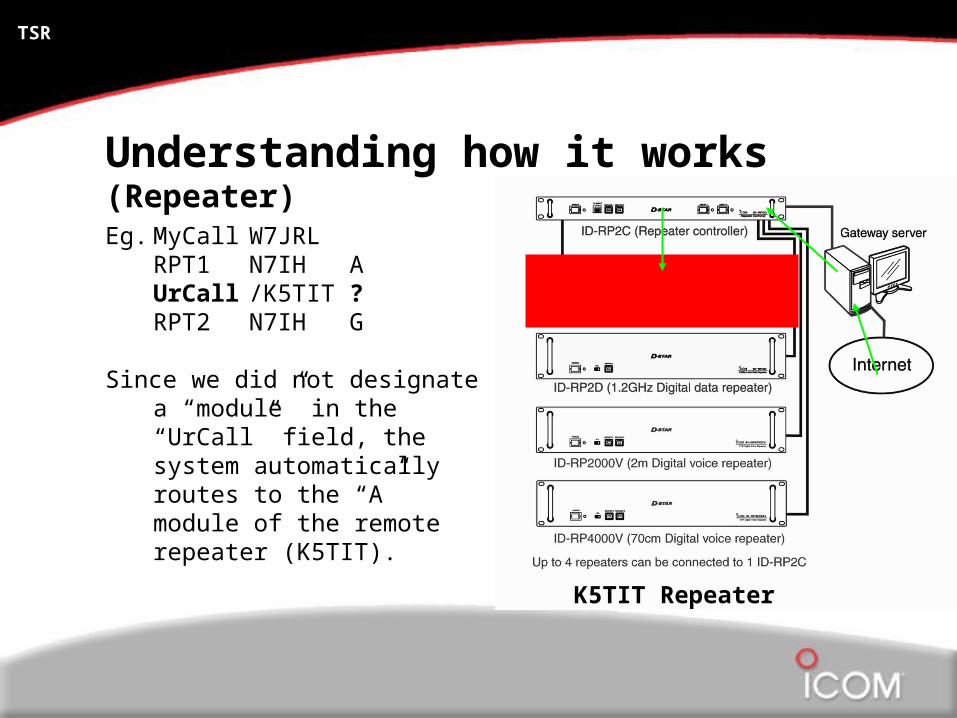
Understanding how it works (Repeater)Eg. MyCall W7JRL
RPT1 N7IH AUrCall /K5TIT ?RPT2 N7IH G
Since we did not designate a “module” in the “UrCall” field, the system automatically routes to the “A” module of the remote repeater (K5TIT).
K5TIT Repeater

TSR
Understanding how it works (Repeater)Eg. MyCall W7JRL
RPT1 N7IH AUrCall /K5TIT CRPT2 N7IH G
If we add the “designator” as the 8th letter, we can route to different modules at the remote repeater site.
K5TIT Repeater

TSR
Understanding how it works (Repeater)Eg. MyCall W7JRL
RPT1 N7IH AUrCall /K5TITRPT2 N7IH G
Currently, you are not able to activate more than 1 module at the remote repeater site.
K5TIT Repeater

TSR
Understanding how it works (Repeater)Eg. MyCall W7JRL
RPT1 N7IH AUrCall N9JARPT2 N7IH G
If you use the call sign of the person you wish to call, the gateway automatically routes the call to the last known location of that call sign within the repeater network.
N7IH Repeater

TSR
Understanding how it works (Gateway)Using the call sign of the desired party to be reached in the “UrCall” field
automatically routes to wherever the radio was last heard.
MyCall – W7JRL
UrCall – N9JA
Rpt1 – N7IH A
Rpt2 – N7IH G
Repeater – N7IH Repeater – W1AW
MyCall - N9JA
UrCall – W7JRL
Rpt1 – W1AW A
Rpt2 – W1AW G
Gateway / Internet
TSR
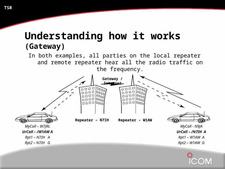
Understanding how it works (Gateway)In both examples, all parties on the local repeater and remote repeater
hear all the radio traffic on the frequency.
MyCall – W7JRL
UrCall – /W1AW A
Rpt1 – N7IH A
Rpt2 – N7IH G
Repeater – N7IH Repeater – W1AW
MyCall - N9JA
UrCall – /N7IH A
Rpt1 – W1AW A
Rpt2 – W1AW G
Gateway / Internet

TSR
Understanding how it works (Gateway)Both radios must be properly programmed to operate via the gateway in
order for transmissions to be heard both directions.
MyCall – W7JRL
UrCall – /W1AW A
Rpt1 – N7IH A
Rpt2 – N7IH G
Repeater – N7IH Repeater – W1AW
MyCall - N9JA
UrCall – /N7IH A
Rpt1 – W1AW A
Rpt2 – W1AW G
Gateway / Internet

TSR
Understanding how it works (Gateway)
In this example, N9JA would hear W7JRL’s transmission but, W7JRL would not hear N9JA since no gateway is selected.
MyCall – W7JRL
UrCall – /W1AW A
Rpt1 – N7IH A
Rpt2 – N7IH G
Repeater – N7IH Repeater – W1AW
MyCall - N9JA
UrCall – /N7IH A
Rpt1 – W1AW A
Rpt2 – none
Gateway / Internet
TSR
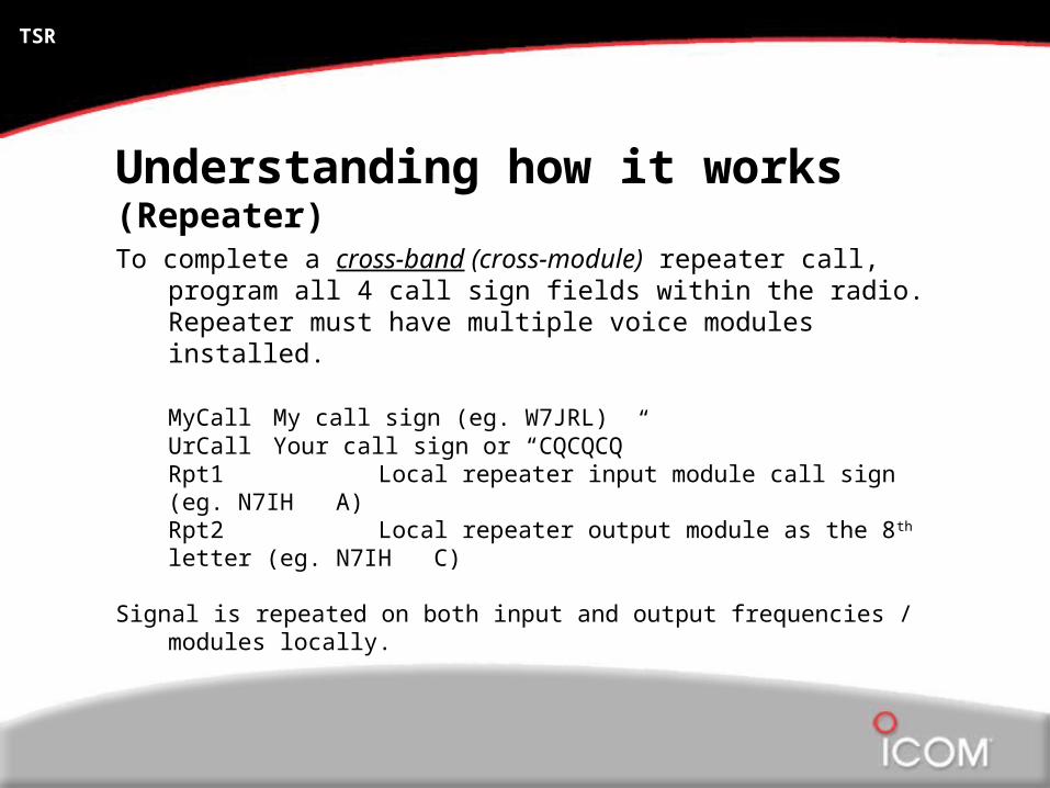
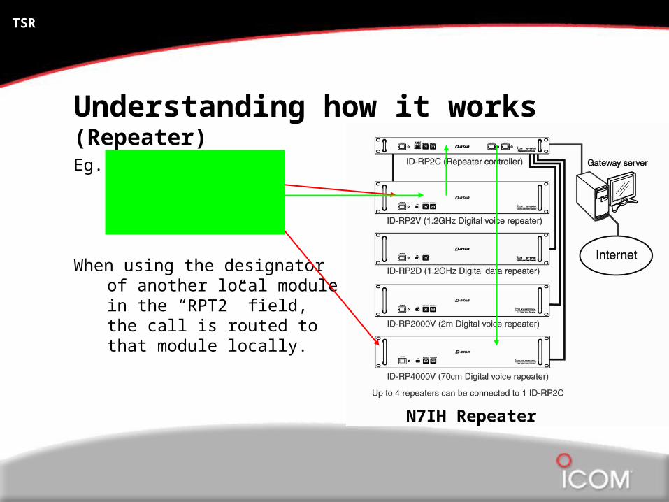
Understanding how it works (Repeater)To complete a cross-band (cross-module) repeater call, program all 4
call sign fields within the radio. Repeater must have multiple voice modules installed.
MyCall My call sign (eg. W7JRL)UrCall Your call sign or “CQCQCQ”Rpt1 Local repeater input module call sign (eg. N7IH A)Rpt2 Local repeater output module as the 8th letter (eg. N7IH C)
Signal is repeated on both input and output frequencies / modules locally.
TSR
Understanding how it works (Repeater)Eg. MyCall W7JRL
RPT1 N7IH AUrCall CQCQCQRPT2 N7IH C
When using the designator of another local module in the “RPT2” field, the call is routed to that module locally.
N7IH Repeater
TSR
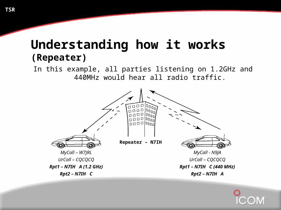
Understanding how it works (Repeater)In this example, all parties listening on 1.2GHz and 440MHz would hear
all radio traffic.
MyCall - N9JA
UrCall – CQCQCQ
Rpt1 – N7IH C (440 MHz)
Rpt2 – N7IH A
MyCall – W7JRL
UrCall – CQCQCQ
Rpt1 – N7IH A (1.2 GHz)
Rpt2 – N7IH C
Repeater – N7IH
TSR
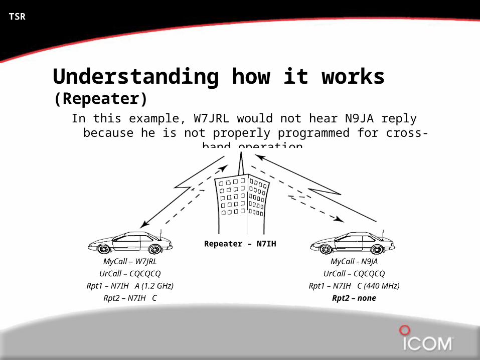
Understanding how it works (Repeater)
In this example, W7JRL would not hear N9JA reply because he is not properly programmed for cross-band operation.
MyCall - N9JA
UrCall – CQCQCQ
Rpt1 – N7IH C (440 MHz)
Rpt2 – none
MyCall – W7JRL
UrCall – CQCQCQ
Rpt1 – N7IH A (1.2 GHz)
Rpt2 – N7IH C
Repeater – N7IH