d.-. National Building Code of Canada 990...d.-. National Building Code of Canada .-- f 990 Second...
46
National Building Code of Canada f 990 -. Second Revisions and Errata Issued by the Canadian Commission on Building and Fire Codes National Research Council of Canada Ottawa January 1992 The attached pages identify revisions and errata to the National Building Code of Canada 1990. The revisions have been approved by the Canadian Commission on Building and Fire Codes for immediate implementation. In accordance with the CCBFC Policies and Proce- dures, the list of referenced documents in Table 2.7.3.A. of the 1990 NBC is updated annually. The revisions contained herein include updates to 30 June 1991. Where significant changes to the title have been made, the relevant requirements have also been updated. The errata are corrections which have been identified and are included to facilitate the use of the Code. Revisions are identified by an r in the margin nearest the change; r2 designates a revision issued in January 1992. Errata are identified by an e.
Transcript of d.-. National Building Code of Canada 990...d.-. National Building Code of Canada .-- f 990 Second...
d.-.
National Building Code of Canada
.-- f 990
.--. Second Revisions and Errata
Issued by the Canadian Commission on Building and Fire Codes National Research Council of Canada Ottawa
- January 1992
The attached pages identify revisions and errata to the National Building Code of Canada 1990. The revisions have been approved by the Canadian Commission on Building and Fire Codes for immediate implementation.
In accordance with the CCBFC Policies and Proce- dures, the list of referenced documents in Table
M 2.7.3.A. of the 1990 NBC is updated annually. The revisions contained herein include updates to 30 June 1991. Where significant changes to the title have been made, the relevant requirements have also been updated.
The errata are corrections which have been identified II- and are included to facilitate the use of the Code.
Revisions are identified by an r in the margin nearest the change; r2 designates a revision issued in January 1992. Errata are identified by an e.

f992 second revisions and errata
Code committee, p. xiii 2.7.3.1. Table 2.7.3.A. 3.1.3.1.(2) 3.2.4.8.(1) 3.2.5.14.(2) 3.3.5.5.W Table 4.1.10.A. 5.4.1.1. 6.2.3.2.(2) Table 9.10.14.B. Span Tables A-9 Appendix A-4.3.4.1. A-8.2.2.12.(3) A.9.3.2.1. Index Earthquake design Trusses Vibrations
I.-
Associate Committee on the National Building Code and
- Standing Committees
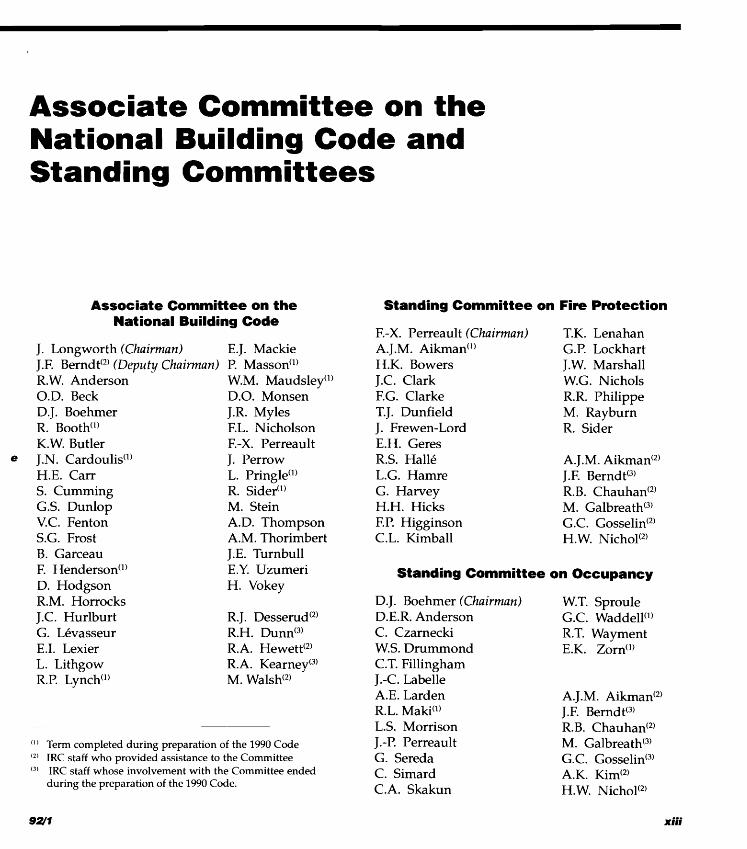
Associate Committee on the National Building Code
J. Longworth (Chairman) E.J. Mackie J.F. Berndt(2) (Deputy Chairman) P. Masson'" R. W. Anderson W.M. Maudsley'l) O.D. Beck D.O. Monsen
a% D.J. Boehmer J.R. Myles R. Booth") F.L. Nicholson K.W. Butler F.-X. Perreault
e J.N. Cardoulis(') J. Perrow H.E. Carr L. Pringle'" S. Cumming R. Sider") G.S. Dunlop M. Stein V.C. Fenton A.D. Thompson S.G. Frost A.M. Thorimbert - B. Garceau J.E. Turnbull F. Henderson'') E.Y. Uzumeri D. Hodgson H. Vokey R.M. Horrocks J.C. Hurlburt R. J. Des~erud(~) G. Lkvasseur R.H. D ~ n n ' ~ ) - E.I. Lexier R.A. H e ~ e t t ' ~ ) L. Lithgow R.A. Kearne~ '~) R.P. Lynch") M. Wal~h '~)
~ C I ( I ' Term completed during preparation of the 1990 Code IRC staff who provided assistance to the Committee IRC staff whose involvement with the Committee ended during the preparation of the 1990 Code.
Standing Committee on Fire Protection
F.-X. Perreault (Chairman) A. J.M. Aikman") H.K. Bowers J.C. Clark F.G. Clarke T. J. Dunfield J. Frewen-Lord E.H. Geres R.S. Hall6 L.G. Hamre G. Harvey H.H. Hicks F.P. Higginson C.L. Kimball
T.K. Lenahan G.P. Lockhart J.W. Marshall W.G. Nichols R.R. Philippe M. Rayburn R. Sider
A. J.M. Aikmad2) J.F. Berndt(3) R.B. Chauhad2) M. Galbreath(3) G.C. Gos~elin(~) H. W. Nich01'~)
Standing Committee on Occupancy
D. J. Boehmer (Chairman) D.E.R. Anderson C. Czarnecki W.S. Drummond C.T. Fillingham J.-C. Labelle A.E. Larden R.L. Maki") L.S. Morrison J.-P. Perreault G. Sereda C. Simard C.A. Skakun
W.T. Sproule G .C. Waddell'') R.T. Wayment E.K. Zorn'l)
A. J.M. Aikrnan(2) J.F. Bernd t(3) R.B. Chauhad2) M. Galbreath(3) G.C. G~sselin '~) A.K. Kim(2) H. W. Nich01'~)
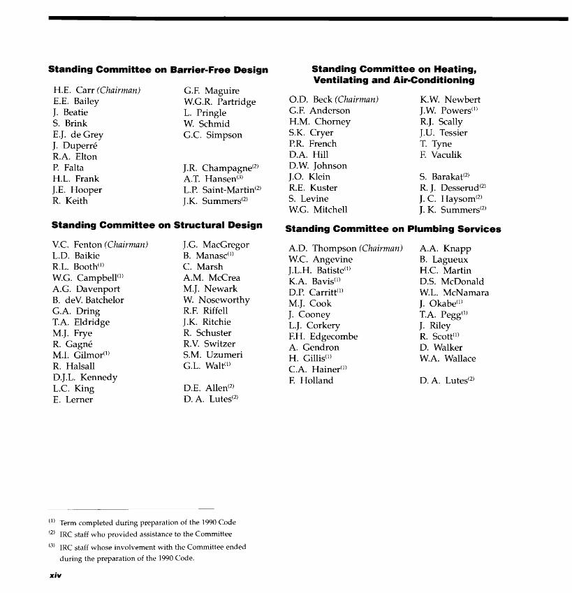
Standing Committee on Barrier-Free Design
H.E. Carr (Chairman) E.E. Bailey J. Beatie S. Brink E.J. de Grey J. Duperre R.A. Elton P. Falta H.L. Frank J.E. Hooper R. Keith
G.F. Maguire W.G.R. Partridge L. Pringle W. Schmid G.C. Simpson
J.R. Cham~agne '~ ) A.T. Hansed3) L.P. Saint-Martid2) J.K. S ~ m m e r s ' ~ )
Standing Committee on Structural Design
V.C. Fenton (Chairman) L.D. Baikie R.L. Booth") W.G. Campbell") A.G. Davenport B. deV. Batchelor G.A. Dring T.A. Eldridge M.J. Frye R. Gagnk M.I. Gilmor") R. Halsall D. J.L. Kennedy L.C. King E. Lerner
J.G. MacGregor B. Manasc(') C. Marsh A.M. McCrea M.J. Newark W. Noseworthy R.F. Riffell J.K. Ritchie R. Schuster R.V. Switzer S.M. Uzumeri G.L. Walt(')
D.E. Alled2) D. A. Luted2)
Standing Committee on Heating, Ventilating and Air-Conditioning
O.D. Beck (Chairman) G.F. Anderson H.M. Chorney S.K. Cryer P.R. French D.A. Hill D.W. Johnson J.O. Klein R.E. Kuster S. Levine W.G. Mitchell
K.W. Newbert J. W. Powers") R.J. Scally J.U. Tessier T. Tyne F. Vaculik
Standing Committee on Plumbing Services
A.D. Thompson (Chairman) W.C. Angevine J.L.H. Batiste") K.A. Bavis") D.P. Carritt") M.J. Cook J. Cooney L.J. Corkery F.H. Edgecombe A. Gendron H. Gillis(') C.A. Hairier")
F. Holland
A.A. Knapp B. Lagueux H.C. Martin D.S. McDonald W.L. McNamara J. Okabe") T.A. Pegg") J. Riley R. Scott'l) D. Walker W.A. Wallace
(') Term completed during preparation of the 1990 Code
(2) IRC staff who provided assistance to the Committee
(3' IRC staff whose involvement with the Committee ended
during the preparation of the 1990 Code.
xiv

n.r,
2.6.2. Review of Construction Section 2.7 Referenced 2.6.2.1. Review of the construction of any building or part thereof shall be carried out by the designer or by another suitably qualified person to determine
,- whether or not the construction conforms to the design.
2.6.3. Review of Shop Drawings 2.6.3.1. The designer or another suitably qualified person shall review all shop drawings and other related documents relevant to the design to deter- - mine conformance with the design.
2.6.4. Workmanship and Materials 2.6.4.1. Workmanship, materials and all reports of material tests shall be reviewed by the designer or other suitably qualified person during the process of construction.
2.6.5. Off-Site Review
- 2.6.5.1. Where a building or component of a building is assembled off the building site in such a manner that it cannot be reviewed on site, off-site reviews shall be provided to determine compliance with this Code.
2.7.1. Application
2.7.1 .I. The provisions of referenced documents in this Code apply only to the extent that they relate to buildings.
2.7.2. Conflicting Requirements
2.7.2. I . In the case of conflict between the provi- sions of this Code and those of a referenced docu- ment, the provisions of this Code shall govern.
2.7.3. Effective Date
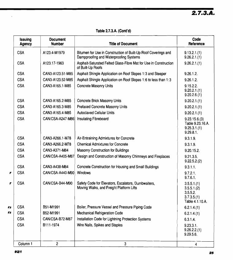
2.7.3.1. Unless otherwise specified herein, the documents referenced in this Code shall include all amendments, revisions and supplements effective to 30 June 1991. r2
2.7.3.2. Where documents are referenced in this Code, they shall be the editions designated in Column 2 of Table 2.7.3.A.
Table 2.7.3.A. Forniing Part of Article 2.7.3.2.
1 Documents Referenced in the National Building Code of Canada 1990 I re".4 Issuing
Title of Document
ASTM ASTM ASTM ASTM ASTM ASTM ASTM
Zinc (Hot-Dip Galvanized) Coatings on lron and Steel Products Zinc Coating (Hot-Dip) on lron and Steel Hardware
Welded and Seamless Steel Pipe Piles Low and Intermediate Tensile Strength Carbon Steel Plates Steel Sheet, Zinc-Coated (Galvanized) by the Hot-Dip Process Steel, Sheet and Strip, Carbon, Hot Rolled, Structural Quality Steel, Cold-Rolled Sheet, Carbon Structural
Table 9.20.1 6.A.
Table 9.20.16.A. 4.2.3.8.
4.2.3.8.
9.3.3.2.
4.2.3.8.
4.2.3.8.
#-
1 column I 2 3 4
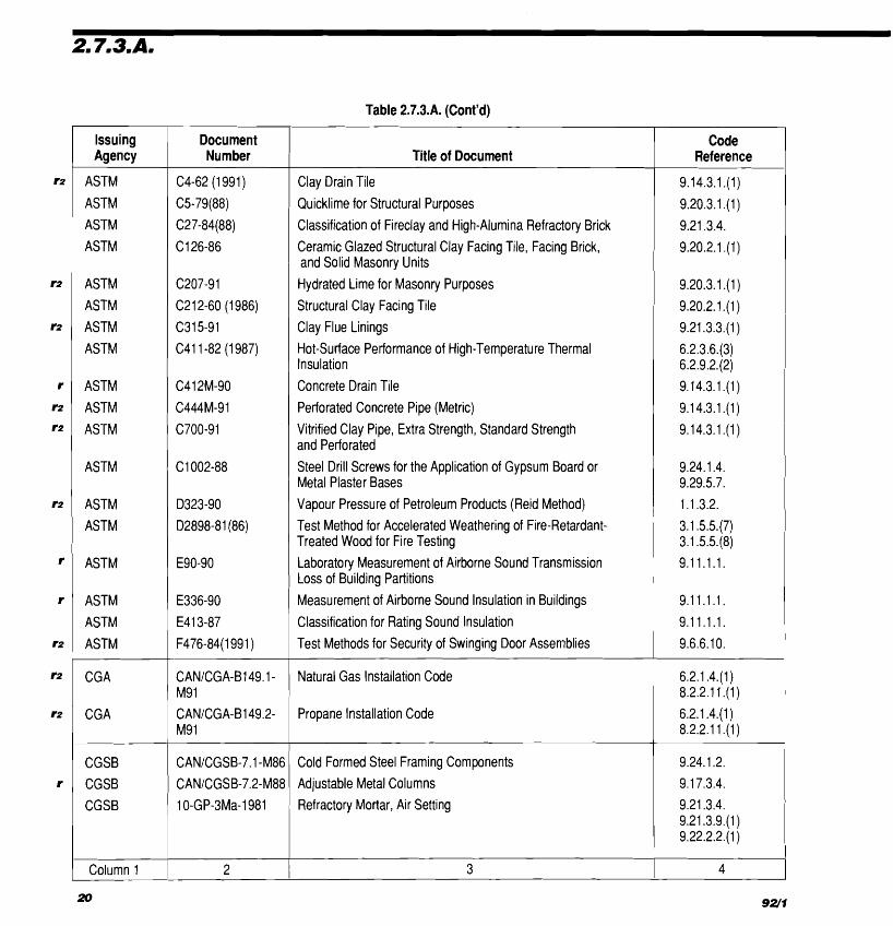
Table 2.7.3.A. (Cont'd)
Issuing Document Agency 1 Number Title of Document Reference I Code I
ASTM
ASTM
ASTM ASTM
ASTM ASTM
ASTM
ASTM
ASTM
ASTM
AS'rM
ASTM
ASTM ASTM
ASTM
ASTM
ASTM ASTM
CGA
CGA
CGSB CGSB CGSB
Clay Drain Tile
Quicklime for Structural Purposes
Classification of Fireclay and High-Alumina Refractory Brick
Ceramic Glazed Structural Clay Facing Tile, Facing Brick, and Solid Masonry Units
Hydrated Lime for Masonry Purposes Structural Clay Facing Tile Clay Flue Linings
Hot-Surface Performance of High-Temperature Thermal Insulation
Concrete Drain Tile
Perforated Concrete Pipe (Me,tric) Vitrified Clay Pipe, Extra Strength, Standard Strength and Perforated Steel Drill Screws for the Application of Gypsum Board or Metal Plaster Bases
Vapour Pressure of Petroleum Products (Reid Method) Test Method for Accelerated Weathering of Fire-Retardant- Treated Wood for Fire Testing Laboratory Measurement of Airborne Sound Transmission
1 Loss of Building Partitions
Measurement of Airborne Sound Insulation in Buildings
Classification for Rating Sound Insulation Test Methods for Security of Swinging Door Asserrlblies - -
I Natural Gas Installation Code
Propane Installation Code
I
Cold Formed Steel Framing Components Adjustable Metal Columns
, Refractory Mortar, Air Setting
I column 1 / 2 3 I 4
;20 92(1

CI
Table 2.7.3.A. (Cont'd)
Issuing Agency
CGSB
CGSB
CGSB
CGSB
CGSB
CGSB
CGSB
CGSB
CGSB
CGSB
CGSB
CGSB
CGSB
CGSB
CGSB
CGSB
CGSB
CGSB
Column 1
Title of Document
Hardboard
Hardboard, Precoated, Factory Finished, for Exterior Cladding
Tempered or Laminated Safety Glass
Flat, Clear Sheet Glass
Flat, Clear Float Glass
Heat Absorbing Glass
Insulating Glass Units
Glass, I-ight and Heat Reflecting
Wired Safety Glass
Structural Design of Glass for Buildings
Sealing Compound, One-Component, Acrylic Base, Solvent Curing Sealing Compound, One-Component, Elastonieric, Chemical Curing
Sealing Compound, One-Component, Butyl-Polyisobutylene Polymer Base, Solvent Curing
Mildew-Resistant Sealing Compound for Tubs and Tile
Multi-Component, Chemical-Curing Sealing Compound
Siding, Asbestos-Cement, Shingles and Clapboards
Sheets, Asbestos-Cement, Corrugated
Sheets, Asbestos-Cement, Decorative
I 3 I
Document Number
CANICGSB-11.3- M87
CANICGSB-11.5- M87 CANICGSB-12.1- M90
CANICGSB-12.2-M91
CANICGSB-12.3-M91
CANICGSB-12.4-M91
CANICGSB-12.8-M90
CAN2-12.10-M76
CANICGSB-12.11- M90
CANICGSB-12.20- M89 19-GP-5M-1976
CANICGSB- 19.1 3-M87
1 9-G P-14M-1976
CANICGSB-19.22- M89
CANICGSB-19.24- M90 CANICGSB-34.4- M89
CANICGSB-34.5- M89 CANICGSB-34.14- M89
1 2
Code Reference
9.27.10.1 .(2) 9.29.7.1. 9.30.2.2.(1)
9.27.1 0.1 .(I)
3.3.1.1 8.(2) 3.4.6.1 4.(3) 9.6.5.2.(2) 9.7.3.1 .(I)
9.7.3.1 .(I)
9.7.3.1 .(I)
9.7.3.1 .(I)
9.7.3.1 .(I)
9.7.3.1 .(I)
3.3.1.18.(2) 3.4.6.1 4.(3) 9.6.5.2.(2) 9.7.3.1 .(I)
4.3.6.1. 9.7.3.2.
9.27.4.2.(2)
9.27.4.2.(2)
9.27.4.2.(2)
9.29.1 0.5.
9.27.4.2.(2)
9.27.8.1 .(I)
9.27.8.1 .(I)
9.27.8.1 .(I)
4

Table 2.7.3.A. (Cont'd)
' Issuing Agency
CGSB
CGSB
CGSB
CGSB
CGSB
CGSB
CGSB
CGSB
CGSB CGSB
CGSB
CGSB CGSB
CGSB CGSB
CGSB
CGSB
CGSB
CGSB CGSB
Column 1
22
Document Number Title of Document
Sheets, Asbestos-Cement, Flat, Fully Compressed
Sheets, Asbestos-Cement, Flat, Semicompressed
Panels, Sandwich, Asbestos-Cement with Insulating Cores
Pipe, Asbestos-Cement, Drain
Emulsified Asphalt , Mineral Colloid Type, Unfilled, for Dampproofing and Waterproofing and for Roof Coatings Application of Emulsified Asphalts for Dampproofing or Waterproofing
Fibrated, Cutback Asphalt, Lap Cement for Asphalt Roofing
Cutback Asphalt Plastic, Cement
Asphalt, Cutback, Unfilled, for Dampproofing Asphalt, Cutback, Filled, for Roof Coating
Primer, Asphalt, Unfilled, for Asphalt Roofing, Dampproofing and Waterproofing
Application of Unfilled Cutback Asphalt for Dampproofing Filled Cutback Asphalt for Dampproofing and Waterproofing
Tar, Cutback, Unfilled, for Dampproofing
Tar, Cutback, Fibrated, for Roof Coating Application of Unfilled Cutback Tar Foundation Coating for Dampproofing Hot Applied Rubberized Asphalt for Roofing and Waterproofing
Application of Hot-Applied RI-~bberized Asphalt for Roofing and Waterproofing Roofing and Waterproofing Membrane, Sheet Applied, Elastomeric Roofing and Waterproofing Membrane, Sheet-Applied, Flexible, Polyvinyl Chloride
c o d e 1 I Reference

Table 2.7.3.A. (Cont'd)
I
Code Reference
9.26.16.1.
9.26.2.1 .(I)
9.26.2.1 .(I)
9.27.13.1.
9.14.3.1 . ( I )
Table 9.23.16.A. 9.25.3.1 . ( I )
Issuing Agency
CGSB
GGSB
CGSB
CGSB
CGSB
CGSB
CGSB
CGSB
CGSB
CGSB
CGSB
CGSB
CGSB
CGSB
CGSB
CGSB
CGSB
CGSB
Column 1
Document Number
37-G P-55M-79
37-G P-56M-80
4.1 -GP-6M-1976
41 -GP-24Ma-1983
41 -GP-29Ma-1983
CANICGSB 51.20- M87
Title of Document
Application of Sheet Applied Flexible Polyvinyl Chloride Roofing Membrane Membrane, Modified,Bituniinous, Prefabricated, and Reinforced for Roofing Sheets, Thermosetting Polyester Plastics, Glass Fiber Reinforced
Sidirrg, Soflits and Fascia, Rigid Vinyl Tubing, Plastic, Corr~~gated, Drainage
Thermal Insulation, Polystyrene, Boards and Pipe Covering
9.25.3.3. I
Table 9.23.16.A. j 9.25.3.1 . ( I )
Table 9.23.1 6.A. 9.25.3.1 . ( I ) i Table 9.23.16.A. 1 9.25.3.1 .(I)
9.25.3.1 . ( I )
9.20.13.10.(1) 9.23.1 7.1. 1 9.26.2.1 .(I) 1 9.25.3.5.(1) I I
51 -GP-21 M-1978
CANICGSB-51.25- M87
CANICGSB-51.26- M86
51 -GP-27M-1979
CAN2-51.32-M77
CANICGSB-51.33- M89 CANICGSB-51.34- M86
CANICGSB-51.60- M-90
CANICGSB-63.14- M89 CANICGSB-82.1- M89 CANICGSB-82.5- M88 CANICGSB-82.6- M86
I 2
9.1 3.2.1 . ( I ) 9.1 8.6.1 .(3) 9.25.3.4.(2) 9.25.3.5.(1)
9.25.3.1 . ( I )
9.7.7.1. 9.7.7.2.
9.6.4.2.
9.6.4.3.
9.6.5.3.
I 4
Thermal Insulation, Urethane and Isocyanurate, Unfaced
Thermal Insulation, Phenolic, Faced
Thermal Insulation, Urethane and Isocyanurate, Boards, Faced
Thermal Insulation, Polystyrene, Loose Fill
Sheathing, Membrane, Breather Type
Vapour Barrier Sheet, Excluding Polyethylene, for Use in Building Construction
Vapour Barrier, Polyethylene Sheet for use in Building Construction
Cellulose Fibre Loose Fill Thermal Insulation
Plastic Skylights
Sliding Doors
Insulated Steel Doors
Doors, Mirrored Glass, Siding or Folding Wardrobe
I 3
I

Table 2.7.3.A. (Cont'd)
Issuing Document 1 Number Title of Document Reference I Code I
CSA CSA
r2
r2
CS A CSA
CGSB CGSB
CSA CSA CSA CSA CSA
CSA CS A
CSA CSA CS A
CSA CSA CSA
1 column I 1 2
Sheet, Aluminum Alloy, Prefinished, Residential
Prefinished Aluminum Siding, Soffits and Fascia for Residential Use Prefinished Galvanized and Aluniinum-Zinc Alloy Steel Sheet for Residential Use Siding, So,ffits and Fascia, Steel, Galvanized, Prefinished, Residential
Portland Cement
Masonry Cement Concrete Materials and Methods of Concrete Construction
Methods of Test for Concrete
Design of Concrete Structures for Buildings Burned Clay Brick (Solid Masonry Units Made ,from Clay or Shale)
Calcium Silicate (Sand-Lime) Building Brick Structural Clay Load-Bearing Wall Tile Structural Clay Non-Load-Bearing Tile Gypsum Plasters Gypsum Board Products
Interior Furring, Lathing and Gypsum Plastering Gypsum Board Application
Aggregate for Masonry Mortar Natural Airflow Ventilators for Buildings Thermal Insulation, Mineral Fibre, for Buildings
Asphalt Shingles Surfaced with Mineral Granules Asphalt Coated Roofing Sheets Asphalt or Tar Saturated Roofing Felt
3
9.20.2.1 . ( I ) 9.20.2.1 .(I) 9.20.2.1 . ( I ) 9.20.3.1 .(I) 3.1.5.1 1 .(4) Table 9.23.16.A. 9.29.5.2. 9.29.4.1. 9.29.5.1 .(2)
9.20.3.1 .(I) 9.19.1.1 .(4) 9.25.3.1 . ( I ) Table 9.23.1 6.A. 9.26.2.1 .(I) 9.26.2.1 . ( I ) 9.26.2.1 .(I)
4
- Table 2.7.3.A. (Cont'd)
Issuing Agency
CSA
CSA
CSA
CS A
CSA
CSA
CSA
CS A
CSA
CSA
CSA
CS A
CSA
CS A
CS A
CSA
CS A CSA
CSA
CS A
Column 1
Title of Document
Bitumen for Use in Construction of Built-up Roof Coverings and Dampproofing and Waterproofing Systems
Asphalt-Saturated Felted Glass-Fibre Mat for Use in Construction of Built-Up Roofs
Asphalt Shingle Application on Roof Slopes 1 :3 and Steeper
Asphalt Shingle Application on Roof Slopes 1 :6 to less than 1 :3
Concrete Masonry Units
Concrete Brick Masonry Units
Prefaced Concrete Masonry Units
Autoclaved Cellular Units
Insulating Fibreboard
Air-Entraining Admixtures for Concrete
Chemical Admixtures for Concrete
Masonry Construction for Buildings
Design and Construction of Masonry Chimneys and Fireplaces
Concrete Construction for Housing and Small Buildings
Windows
Safety Code for Elevators, Escalators, Dumbwaiters, Moving Walks, and Freight Platform Lifts
Boiler, Pressure Vessel and Pressure Piping Code Mechanical Refrigeration Code
Installation Code for Lightning Protection Systems
Wire Nails, Spikes and Staples
I 3
Document Number
A1 23.4-MI 979
A1 23.1 7-1963
CAN3-A123.51 -M85
CAN3-A123.52-M85
CAN3-A165.1 -M85
CAN3-A165.2-M85
CAN3-A165.3-M85
CAN3-A165.4-M85
CANICSA-A247-M86
CAN3-A266.1 -M78
CAN3-A266.2-M78
CAN3-A371 -M84
CANICSA-A405-M87
CAN3-A438-M84
CANICSA-A440-M90
CANICSA-B44-M90
B51 -MI 991
B52-MI 991
CANICSA-B72-M87
B111-1974
I 2
Code Reference
9.13.2.1 .(I) 9.26.2.1 .(I)
9.26.2.1 .(I)
9.26.1 -2.
9.26.1.2.
9.1 5.2.2. 9.20.2.1 .(I) 9.20.2.6.(1)
9.20.2.1 .(I)
9.20.2.1 .(I)
9.20.2.1 .(I)
9.23.1 5.6.(3) Table 9.23.1 6.A. 9.25.3.1 .(I) 9.29.8.1.
9.3.1.9.
9.3.1.9.
9.20.15.2.
9.21.3.5. 9.22.5.2.(2)
9.3.1 . l .
9.7.2.1. 9.7.6.1.
3.5.5.1 .(I) 3.5.5.1 .(2) 3.5.5.2. 3.7.3.5.(1) Table 4.1 .10.A.
6.2.1.4.(1)
6.2.1.4.(1)
6.3.1.4.
9.23.3.1. 9.26.2.2.(1) 9.29.5.6.
4

Table 2.7.3.A. (Cont'd)
Issuing Agency
CSA
CSA
CS A
CSA
CS A
CS A
CSA
CS A
CS A
CS A
CS A
CS A
CSA
CS A
CS A
CS A
CS A
Column 1 I 2 3 4
Document Number
CANICSA-B139-M91
CANICSA-B182.1-87
8228.1 -1 968
CANICSA-B355-M86
CANICSA-B365-M91
C22.1-1990
C22.2 No. 0.3-MI985
C22.2 No.113-MI984
C22.2 No.141 -MI 985
CANICSA-C282-M89
CANICSA-C444-M87
CANICSA-F280-M90
CANICSA-G40.21- M9 1
CAN3-G401 -M81
CANICSA-080-M89
CANICSA-080.1- M89 CANICSA-080.2- M89
Title of Document
Installation Code for Oil Burning Equipment
Plastic Drain and Sewer Pipe and Pipe Fittings
Pipes, Ducts, and Fittings for Residential Type Air Conditioning Systems
Elevating Devices for the Handicapped
Installation Code for Solid-Fuel Burning Appliances and Equipment
Canadian Electrical Code, Part 1
Test Methods for Electrical Wires and Cables
Fans and Ventilators
Unit Equipnient for Emergency Lighting
Emergency Electrical Power Supply for Buildings
Installation Requirements for Heat Recovery Ventilators
Determining the Required Capacity of Residential Space Heating and Cooling Appliances
Structural Quality Steels
Corrugated Steel Pipe Products
Wood Preservation
Preservative Treatment of All Timber Products by Pressure Processes Preservative Treatment of Lumber, Timber, Bridge Ties, and Mine Ties by Pressure Processes
Code Reference
6.2.1.4.(1) 8.2.2.1 1 .(I)
9.14.3.1 . ( I )
6.2.4.2.(2)
3.7.3.5.(2)
6.2.1.4.(1) 9.21 . I .3.(2) 9.22.10.1. 9.33.1.2.
3.5.1.2. 3.5.2.1 .(5) 3.5.2.9.(1) 6.2.1.4.(1) 8.2.2.9.(2) 9.34.1 . l .
3.1.4.3.(1) 3.1.5.17.(1) 3.5.4.3.(1)
9.32.3.3.(2)
3.2.7.4.(2) 9.9.1 1.3.(6)
3.2.7.5.
6.2.1.7.
6.2.1.2.
4.2.3.8. 9.23.4.2.(2)
9.14.3.1 .(I)
3.1.4.4.(1)
9.3.2.9.(1)
4.2.3.2. 9.3.2.9.(1)

a C *
Table 2.7.3.A. (Cont'd)
as-
Code Reference
4.2.3.2.
9.3.2.9.(1)
4.2.3.2. 9.3.2.9.(1) 4.3.1 .l.
Table 4.1.9.8. 4.3.1 . l .
9.27.9.1. 9.30.2.2.(1)
9.26.2.1 .(I) 9.27.7.1 .(I)
9.23.14.2.(1) 9.23.1 5.1 .(I) Table 9.23.16.A. 9.27.9.1. 9.30.2.2.(1)
9.23.4.3.(2)
9.6.4.1 .(I)
3.1.4.6.(2) 9.3.2.6.
9.23.14.2.(1)
9.23.1 5.1 .(I)
Table 9.23.1 6.A.
9.27.9.1 . 9.30.2.2.(1)
9.23.1 4.2.(1) 9.23.1 5.1 .(I) Table 9.23.1 6.A. 9.27.9.1. 9.30.2.2.(1) 4.3.1.2.
4
Issuing Agency
CSA
CSA
CSA
CS A
CSA
CSA
CSA
CSA
CS A
CSA
CSA
CS A
CSA
CS A
Column 1 I
Document Number
CANlCSA-080.3- M89
CANlCSA-080.9- M I 989
CANlCSA-080.15- M89
CAN3-086-M84
CANlCSA-086.1- M89 0 1 15-MI 982
0 1 18.1 -M88
0 1 21 -MI 978
CANlCSA-0122- M89
CANlCSA-0132.2- M90
CANICSA-014.1-91
0 1 51 - M I 978
0 1 53-MI980
CANlCSA-0177- M89
2
Title of Document
Preservative Treatment of Piles by Pressure Processes
Preservative Treatment of Plywood by Pressure Processes
Preservative Treatment of Wood for Building Foundation Systems, Basements, and Crawl Spaces by Pressure Processes
Engineering Design in Wood (Working Stress Design)
Engineering Design in Wood ( Limit States Design)
Hardwood and Decorative Plywood
Western Red Cedar Shingles and Shakes
Douglas Fir Plywood
Structural Glued-Laminated Timber
Wood Flush Doors
Softwood Lumber
Canadian Softwood Plywood
Poplar Plywood
Qualification Code for Manufacturers of Structural Glued- Laminated Timber
I 3
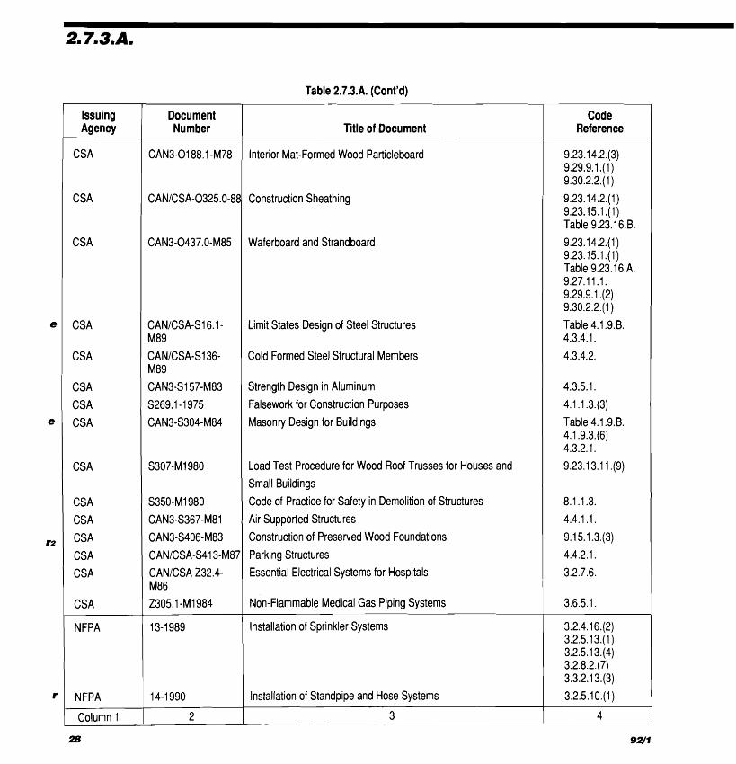
Table 2.7.3.A. (Cont'd)
Issuing Agency
CSA
CSA
CSA
CSA
CSA
CSA
CSA
CSA
CS A
CS A
CS A
CS A
CS A
CSA
CSA
NFPA
NFPA
Column 1
Code Reference
9.23.1 4.2.(3) 9.29.9.1 . ( I ) 9.30.2.2.(1)
9.23.14.2.(1) 9.23.15.1 .(I) Table 9.23.1 6.B.
9.23.1 4.2.(1) 9.23.15.1 . ( I ) Table 9.23.16.A. 9.27.1 1.1. 9.29.9.1 .(2) 9.30.2.2.(1)
Table 4.1.9.B. 4.3.4.1.
4.3.4.2.
4.3.5.1.
4.1.1.3.(3)
Table 4.1.9.B. 4.1.9.3.(6) 4.3.2.1.
9.23.13.1 1 .(9)
8.1.1.3.
4.4.1 . I .
9.1 5.1.3.(3)
4.4.2.1.
3.2.7.6.
3.6.5.1.
3.2.4.1 6.(2) 3.2.5.13.(1) 3.2.5.1 3.(4) 3.2.8.2.(7) 3.3.2.1 3.(3)
3.2.5.1 0.(1)
4
Document Number
CAN3-0188.1 -M78
CANICSA-0325.0-88
CAN3-0437.0-M85
CANICSA-S16.1- M89
CANICSA-S136- M89
CAN3-S157-M83
S269.1-1975
CAN3-S304-M84
S307-MI 980
S350-MI 980
CAN3-S367-M81
CAN3-S406-M83
CANICSA-S413-M87
CANICSA 232.4- M86 2305.1 -MI 984
13-1 989
14-1 990
2
Title of Document
Interior Mat-Formed Wood Particleboard
Construction Sheathing
Waferboard and Strandboard
Limit States Design of Steel Structures
Cold Formed Steel Structural Members
Strength Design in Aluminum
Falsework for Construction Purposes
Masonry Design for Buildings
Load Test Procedure for Wood Roof Trusses for Houses and
Small Buildings
Code of Practice for Safety in Demolition of Structures
Air Supported Structures
Construction of Preserved Wood Foundations
Parking Structures
Essential Electrical Systems for Hospitals
Non-Flammable Medical Gas Piping Systems
Installation of Sprinkler Systems
Installation of Standpipe and Hose Systems
3
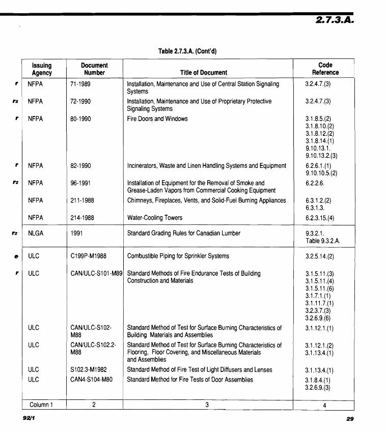
Table 2.7.3.A. (Cont'd)
Code Reference
3.2.4.7.(3)
3.2.4.7.(3)
3.1.8.5.(2) 3.1.8.1 042) 3.1.8.1 2.(2) 3.1.8.14.(1) 9.10.13.1. 9.1 0.1 3.2.(3)
6.2.6.1 .(I) 9.10.10.5.(2)
6.2.2.6.
6.3.1.2.(2) 6.3.1.3.
6.2.3.1 5.(4)
9.3.2.1. Table 9.3.2.A.
3.2.5.14.(2)
3.1.5.1 1 .(3) 3.1.5.1 144) 3.1.5.1 1 .(6) 3.1.7.1 .(I) 3.1 .I 1.7.(1) 3.2.3.7.(3) 3.2.6.9.(6)
3.1.12.1 .(I)
3.1.12.1 .(2) 3.1.1 3.4.(1)
3.1.1 3.4.(1)
3.1.8.4.(1) 3.2.6.9.(3)
4
Issuing Agency
NFPA
NFPA
NFPA
NFPA
NFPA
NFPA
NFPA
NLGA
ULC
ULC
ULC
ULC
ULC
/I LC
Column 1
Document Number
71 -1 989
72- 1 990
80- 1 990
82- 1 990
96-1 991
21 1-1988
21 4-1 988
1991
C199P-MI988
CANIULC-S1 01 -M89
CANIULC-S102- M88
CANIULC-S102.2- M88
S102.3-MI 982
CAN4-S104-M80
1 2
Title of Document
Installation, Maintenance and Use of Central Station Signaling Systems
Installation, Maintenance and Use of Proprietary Protective Signaling Systems
Fire Doors and Windows
Incinerators, Waste and Linen Handling Systems and Eql~ipment
Installation of Equipment for the Removal of Smoke and Grease-Laden Vapors from Commercial Cooking Equipment
Chimneys, Fireplaces, Vents, and Solid-Fuel Burning Appliances
Water-cooling Towers
Standard Grading Rules for Canadian Lumber
Corr~bustible Piping for Sprinkler Systems
Standard Methods of Fire Endurance Tests of Building ConstrucEion and Materials
Standard Method of Test for Surface Burning Characteristics of Building Materials and Assemblies
Standard Method of Test for Surface Burning Characteristics of Flooring, Floor Covering, and Miscellaneous Materials and Assemblies
Standard Method of Fire Test of Light Diffusers and Lenses
Standard Method for Fire Tests of Door Assemblies
I 3

Table 2.7.3.A. (Cont'd)
Issuing Document 1 Number Title of Document
ULC
ULC
ULC
ULC
ULC
ULC ULC
ULC
ULC
ULC
ULC
ULC
ULC LILC
Ll LC
Ll LC ULC Ll LC ULC
Column 1
Standard Speci,fication for Fire Door Franies Meeting the Performance Required by CAN4-S104
Standard Method for Fire Tests of Window and Glass Block Assemblies
Standard Methods of Fire Tests of Roof Coverings
Standard for Flame Tests of Flame-Resistant Fabrics and Films
Standard Methods of Test for Air Ducts
Standard Method of Fire Tests for Air Filter Units Standard Method of Fire Test of Fire-Damper Assemblies
Standard Speci,fication for Wood Core Doors Meeting the Performance Required by CAN4-S104-77 for Twenty Minute Fire Rated Closure Assemblies Standard Method of Test for Deterrr~ination of Non-Combustibility in Building Materials
Standard Method of Fire Tests for Fire Stop Systems
Standard Method of Test for the Evaluation of Protective Coverings for Foamed Plastic Standard Method of Test For Fire Spread under Roof-Deck Assemblies Standard for Fusible Links for Fire Protection Service Standard for the Installation of Fire Alarm Systems Standard for Smoke Alarms
Standard for the Verification of Fire Alarni Systems Standard for Factory-Built Fireplaces Standard for 650°C Factory-Built Chimneys Standard for Steel Liner Assemblies for Solid-Fuel Burning Masonry Fireplace
3
Reference I Code I

Part 3 Use and Occupancy
- (See Appendix A)
Section 3.1 General 3 . 1 1 Scope 3.1 .I .I. Scope. The scope of this Part shall be as described in Section 2.1.
3.1 .I .2. Defined Words. Words that appear in a".- italics are defined in Part 1.
3.1 .I .3. Fire Protection Information. Infor- mation to be submitted regarding major compo- nents of fire protection shall conform to the require- ments in Article 2.3.3.1.
3.1.2. Classification of Buildings or Parts of Buildings by Major Occupancy (See Appendix A.)
3.1.2.1. Classification of Buildings (1 ) Except as provided in Articles 3.1.2.3. to
3.1.2.5., every building or part thereof shall be classi- fied according to its major occupancy as belonging to
*I.
one of the Groups or Divisions described in Table 3.1.2.A.
(2) A building intended for use by more than one major occupancy, shall be classified according to all major occupancies for which it is used or intended to be used.
*- 3.1.2.2. Occupancies of Same Classif ica- tion. Any building is deemed to be occupied by a single major occupancy, notwithstanding its use for more than one major occupancy, provided that such
occupancies are classified as belonging to the same Group classification or, where the Group is divided into Divisions, as belonging to the same Division classification in Table 3.1.2.A.
3.1.2.3. Arena Type Buildings. An arena type building intended for occasional use for trade shows and similar exhibition purposes shall be classified as Group A, Division 3 occupancy and, when the building area of such building is more than 1 500 m2, the building shall be sprinklered. (See Appendix A.)
3.1.2.4. Police Stations. Police stations with detention quarters are permitted to be classified as Group B, Division 2 major occupancies provided such stations are not more than 1 storey in building height and 600 m2 in building area.
3.1.2.5. Convalescent and Childrensv Custodial Homes. Convalescent homes and children's custodial homes are permitted to be classified as Group C major occupancies provided that occupants are ambulatory and live as a single house- keeping unit in a dwelling unit with sleeping accom- modation for not more than 10 persons.
3.1 .3. Multiple Occupancy Requirements
3.1.3.1. Buildings with Multiple Occupancies
(1 ) The requirements restricting fire spread and collapse for a building of a single major occupancy classification are provided in Subsection 3.2.2. according to its building height and building area.

Table 3.1.2.A. Forming Part of Sentence 3.1.2.1 .(I )
Group
A
A
A A
B
B
C D E
F F F
Col. 1
Note to Table 3.1.2.A.: ('1 See Appendix A.
(2) Where any building contains more than 3.1 3.4. Superimposed Major Occupancies e one major occupancy classified in more than one (1 ) Except as permitted in Article 3.1.3.5., in
Group or Division, the requirements of Subsection any building in which one major occupancy is located 3.2.2. concerning building size and construction entirely above another major occupancy, the require- relative to occupancy shall apply according to Articles ments in Subsection 3.2.2. for each portion of the 3.1.3.2 to 3.1.3.5. building containing a major occupancy shall apply to
3.1 3.2. Applicable Building Height and that portion as if the entire building was of that major
Area. In determining the fire safety requirements of oCCUPanCy. a building in relation to each of the major occupancies (2) Where one major occupancy is located contained.therein, the building height and* building area above another, the fire-resistance rating of the floor of the entire building shall be used. assembly between such major occupancies shall be
determined on the basis of the requirements in 3.1 3.3. Construction Requiremants. Ex- Subsection 3.2.2. for the lower major occupancy. (See cept as provided in Articles 3.1 3.4. and 3.1 3 .5 , in also ~ ~ ~ i ~ l ~ 3.1.3.6.) any building containing more than one major occu- pancy, the requirements of Subsection 3.2.2. for the 3.1 .Urn Exceptions for Major Occu- most restricted major occupancy contained shall apply In a building where the aggregate area of to the whole building. all mjm occupancies in a particular Group or Division
34 9a*
--- -- -- - ----A
Division
1
2
3
4
1
2
- - -
1
2
3 2
Description of Major Occupancies ('1
Assembly occupancies intended for the production and viewing of the performing arts Assembly occupanies not elsewhere classified in Group A Assembly occupancies of the arena type Assembly occupancies in which provision is made for the congregation or gathering of persons for the purpose of participating in or viewing open air activities Institutional occupancies in which persons are under restraint or are incapable of self preservation because of security measures not under their control Institutional occupancies in which persons because of mental or physical limitations require special care or treatment
Residential occupancies Business and personal services occupancies
Mercantile occupancies High hazard industrial occupancies Medium hazard industrial occupancies Low hazard industrial occupancies
3

(a) cause an alert signal to sound upon the operation of any manual pull station or fire detector,
(b) automatically cause an alarm signal to sound if the alert signal is not acknowl- edged within 5 min of its initiation, and
(c) have each manual pull station equipped so that the use of a key or other similar device causes an alarm signal to sound and continue to sound upon the removal of the key or similar device from the manual pull station.
(See Appendix A.)
(3) Fire alarm systems in Sentences (1) and (2) are permitted to be zone coded so that, upon the operation of any manual pull station or fire detector,
(a) a coded alarm signal is sounded for a single stage system or a coded alert signal is sounded for a 2 stage system indicating the zone of alarm initiation,
(b) the coded alert signal or alarm signal is repeated in its entirety not less than 4 times, and
(c) a continuous alert signal or a l u m signal is sounded upon completion of the coded signals in Clause (b) and Sentence (4).
(4) When a second manual pull station or fire detector is operated in a system in Sentence (3), in a zone other than that for which the first alert signal or alarm signal was sounded, the coded alert signal or alarm signal for the first zone shall be completed before the coded alert signal or alarm signal for the second zone is repeated not less than 4 times.
3.2.4.5. Installation and Testing of Fire Alarm Systems
( I ) Fire alarm and voice communication systems shall be installed in conformance with CAN/ ULC-S524-M, "Standard for the Installation of Fire Alarm Systems."
(2) Fire alarm systems shall be tested to ensure satisfactory operation in conformance with CAN/ULC-S537-M,"Standard for the Verification of Fire Alarm Systems."
3.2.4.6. Silencing of Alarm Signals (1 ) Required fire alarm systems shall be
designed so that when an a l u m signal is actuated, it cannot be silenced automatically for at least
(a) 5 min for buildings not required to be equipped with an annunciator, and
(b) 20 min for all other buildings. (2) Except as permitted in Sentence
3.2.4.22.(2), a required fire alarm system shall not incorporate manual silencing switches other than those installed inside the fire alarm control unit. (See Appendix A.)
3.2.4.7. Signals to Fire Department (1 ) Where a fire alarm system is required to
be installed, and a single stage system is provided, the system shall be designed to notify the fire depart- ment in conformance with Sentence (3) that an alarm signal has been initiated in
(a) Group A occupancies having an occupant load of more than 300,
(b) Group B occupancies, (c) Group F, Division 1 occupancies, (d) buildings regulated by the provisions of
Subsection 3.2.6., or (e) buildings containing interconnected floor
space required to conform to Articles 3.2.8.3. to 3.2.8.9.
(2) Where a fire alarm system is required to be installed and a 2 stage system is provided, the system shall be designed to notify the fire depart- ment in conformance with Sentence (3) that an alert signal has been initiated.
(3) Except as permitted in Sentence (4), signals to the fire department shall be by way of
(a) the municipal fire alarm system, (b) an independent central station conforming
to NFPA-71, "Installation, Maintenance, and Use of Central Station Signaling Systems," or
(c) a proprietary control centre conforming to NFPA-72D, "Installation, Maintenance, and Use of Proprietary Protective Signal- ing Systems."
(4) When the facilities in Sentence (3) are not available in the municipality in which the building is to be built, an independent system is permitted to be used to transmit signals to the fire department.
(5) Where a required fire alarm system has been installed with no provisions to transmit a signal to the fire department as indicated in Sentences (2), (3) and (4), a legible, permanently-mounted notice

shall be posted at each manual pull station request- ing that the fire department be notified and including the telephone number of that department.
1 3.2.4.8. Annunciator and Zone Indication
(2) An annunciator need not be provided for a fire alarm system when not more than one zone indicator is required in Sentence (1).
e
(3) When an annunciator is not installed as part of a required fire alarm system in conformance with Sentence (I), a visual and audible trouble signal device shall be provided inside the main entrance of the building.
(1) Except as permitted in Sentences (2) to (5), an annunciator shall be installed in close proximity to a building entrance that faces a street or an access route for fire department vehicles that complies with Sentence 3.2.5.6.U ) and the annunciator shall have separate zone indicators of the actuation of the alarm
(4) The requirements in Sentence (1) are waived in a building that has an aggregate area for all storeys of not more than 2 000 m2 and is not more than 3 storeys in building height.
initiating devices in each (a) floor area so that the area of coverage for
each zone is not more than 2 000 m2, (b) fire compartment required to be separated
by vertical fire separations having a fire- resistance rating of not less than 2 h, other than dwelling units described in Subsection 3.3.4.,
(c) shaft required to be equipped with fire detectors,
(d) air handling system required to be equipped with smoke detectors,
I (e) contained use area, and (f) impeded egress zone.
(See Appendix A.)
(5) Where a sprinkler system is used in lieu of heat detectors in conformance with Article 3.2.4.16., the requirements for zone indication in Clauses (l)(a) and (b) are waived provided the actuation of the alarm initiating devices is indicated on the annuncia- tor in conformance with the zone indication require- ments for the sprinkler system. (See Appendix A.)
3.2.4.9. Electrical Supervision. Electrical supervision shall be provided for required fire alarm systems.
3.2.4.1 0. Fire Detectors (1 ) Fire detectors required in this Article shall
be connected to the fire alarm system.
(2) Except as provided in Article 3.2.4.16., where a fire alarm system is required, fire detectors shall be installed in
(a) storage rooms not within dwelling units, (b) service rooms not within dwelling units, (c) janitors' rooms, (d) elevator and dumbwaiter shafts, and
I (e) rooms where hazardous products are to be
used or stored.
3.2.4.1 I. Heat Detectors (1 ) Except as provided in Article 3.2.4.16.,
where a fire alarm system is required, heat detectors shall be installed
(a) in every room in portions of buildings classified as Group A, Division 1 or Group B major occupancy other than sleeping rooms, and
(b) in every suite and every room not located within a suite, in portions of buildings classified as Group C major occupancy and more than 3 storeys in building height. (See also Article 3.2.4.21. for smoke alarms.)
3.2.4.1 2. Smoke Detectors (1) Where a fire alarm system is required,
smoke detectors shall be installed in (a) every sleeping room and every corridor
serving as part of a means of egress from sleeping rooms in portions of buildings classified as Group B major occupancy,
(b) every room in a contained use area and corridors serving those rooms,
(c) every corridor in portions of buildings classified as Group A, Division 1 major occupancy,
(d) every public corridor in portions of buildings classified as Group C major occupancy,
(e) every exit stair shaft, and (f) the vicinity of draft stops required by
Article 3.2.8.7. (See Appendix A.)

(c) fire protection equipment is available to deliver, by means of the fire department connection, the full demand flow rate at a residual water pressure of 450 kPa at the topmost outlet of the standpipe and hose system. (See Appendix A.)
3.2.5.1 1. Hose Stations and Cabinets (1) Required hose stations shall be located in
or near exits, and where a pressurized vestibule is provided adjacent to exit stairs, the hose station shall be located w'ithin the pressurized vestibule.
(2) A hose station located on one side of a horizontal exit shall be considered to serve only the floor area on that side of such exit.
(3) Every hose cabinet shall be located so that its door, when fully opened, will not obstruct the required width of a means of egress.
(4) Hose connections shall be provided with sufficient clearance to permit the use of a standard fire department hose key.
(5) Fire hose stations in a Group B, Division 1 major occupancy are permitted to be located in secure areas, or in lockable cabinets provided that
(a) identical keys for all cabinets are located at all guard stations, or
(b) electrical remote release devices are provided and are connected to an emer- gency power supply.
3.2.5.1 2. Trouble Signal Annunciation for Valves. In buildings where a fire alarm system is required to have an annunciator by Sentence 3.2.4.8.(1), except for hose valves, all valves control- ling water supplies in a standpipe and hose system shall be equipped with an electrically supervised switch for transmitting a trouble signal to the annun- ciator in the event of movement of the valve handle.
3.2.5.1 3. Automatic Sprinkler Systems (1 ) Except as provided in Sentences (2) and
(3), where a sprinkler system is required, it shall be designed, constructed, installed and tested in confor- mance with NFPA 13, "Installation of Sprinkler Systems." (See Appendix A.)
(2) Where a building contains fewer than 9 sprinklers, the water supply for such sprinklers is permitted to be supplied from the domestic water
system for the building provided the required flow for the sprinklers can be met by the domestic system.
(3) Where a water supply serves both a sprinkler system and a system serving other equip- ment, control valves shall be provided so that either system can be shut off independently.
(4) Open grid and translucent ceilings located below sprinkler systems shall be installed in confor- mance with NFPA 13, "Installation of Sprinkler Systems," paragraphs 4-4.14 and 4-4.1 5.
3.2.5.1 4. Combustible Sprinkler Piping (1 ) Combustible sprinkler piping shall be used
only for wet systems in residential occupancies and other light hazard occupancies. (See Appendix A.)
(2) Combustible sprinkler piping shall meet the requirements of ULC C199P-M, "Combustible Piping for Sprinkler Systems."
(3) Combustible sprinkler piping shall be separated from the area served by the sprinkler system and from any other fire compartment by ceilings, walls, or soffits consisting of, as a minimum, lath and plaster, gypsum board not less than 9.5 mm thick, plywood not less than 13 mm thick, or a suspended membrane ceiling with lay-in panels or tiles and steel suspension grids, with the lay-in panels or tiles having a mass of at least 1.7 kg/m2.
(4) Where combustible sprinkler piping is located above a ceiling, an opening through the ceiling that is not protected in conformance with Sentence (3) shall be located so that the distance between the edge of the opening and the nearest sprinkler is not more than 300 mm.
3.2.5.1 5. Sprinklered Service Space (1 ) An automatic sprinkler system shall be
installed in a service space referred to in Sentence 3.2.1.1.(7) if flooring for access within the service space is other than catwalks.
(2) The sprinkler system required by Sentence (1) shall be equipped with waterflow detecting devices with each device serving not more than one storey.
(3) The waterflow detecting devices required by Sentence (2) shall be connected to the fire alarm system, if required, to I
I

(a) initiate an alert signal or an alarm signal, and
(b) indicate separately on the fire alarm system annunciator the actuation of each device.

(3) A single exit is permitted from a dwelling unit provided the exit is an exterior doorway not more than 1.5 m above adjacent ground level and
(a) it is not necessary to travel up or down more than 1 storey to reach the exit door, or
(b) the uppermost floor level opens to a balcony not more than 6 m above adjacent ground level.
(4) An egress door from either the uppermost storey or the lowest storey in a dwelling unit, as re- quired in Sentence (2), need not be provided where that storey is served by a stairway that
(a) leads to a public access to exit, (b) has no direct access to any other storey in
the dwelling unit, and (c) is separated from the other storeys in the
dwelling unit by a fire separation having a fire-resistance rating of not less than 45 min.
(5) In buildings of residential occupancy not more than 3 storeys in building height, a doorway from a dwelling unit is permitted to open directly into an exit stairway provided such dwelling unit has a second and separate means of egress.
(6) A doorway from a dwelling unit is permit- ted to open onto an interior corridor served by a single exit, or an exterior balcony served by a single exit stairway, or an exterior passageway served by a single exit stairway provided each dwelling unit has a second and separate means of egress.
3.3.4.5. Automatic Locking Prohibition. Except for hotels and motels, a door opening onto a public corridor which provides access to exit from a suite shall be designed not to lock automatically. (See Appendix A.)
3.3.4.6. Sound Transmission. Dwelling units shall be designed and constructed to restrict sound transmission in conformance with Article 9.1 1.2.1.
3.3.4.7. Guards for Residential Occu- pancies. Guards around balconies in buildings of residential occupancy shall be designed so that no member, attachment or opening located between 100 mm and 900 mm above the balcony will facilitate climbing.
3.3.4.8. Stairs, Handrails and Guards for Dwelling Units. Stairs, handrails and guards
within dwelling units shall conform to the appropriate requirements in Section 9.8.
3.3.5. Industrial Occupancy
3.3.5.1. Scope. This Subsection applies to floor areas or parts thereof used or intended for use as industrial occupancies.
3.3.5.2. Fire Extinguishing Systems. In addition to other requirements in this Code for the installation of automatic fire extinguishing systems, in a Group F, Division 1 major occupancy, an appropri- ate automatic fire extinguishing system shall be installed in every floor area to provide protection if required by provincial, territorial or municipal regulations or, in the absence of regulations, if required by the National Fire Code of Canada 1990.
3.3.5.3. Basements (1 ) Basements shall not be used for the storage,
manufacture or handling of volatile solids, liquids or gases that generate explosive air-vapour mixtures or for processes that involve explosive dusts.
(2) Entrances and exits to basements and rooms containing building services in a building where the storage, manufacture or handling of volatile materi- als can generate explosive air-vapour mixtures or where processes that produce explosive dusts can occur shall be separate from the remainder of the building.
(3) Basements and rooms referred to in Sen- tence (2) shall be separated from the remainder of the building with a vapour-tight separation.
3.3.5.4. Cutting and Welding. Where a room in other than a Group F major occupancy is used for cutting and welding operations, it shall be separated from the remainder of the building by a fire separation having a fire-resistance rating of not less than 1 h, except that this requirement does not apply to a room that is protected by an automatic fire extinguishing system.
3.3.5.5. Repair and Storage Garages (1 ) Where access is provided from a storage
garage to a stair tower or elevator serving occupancies above the level of the storage garage, such access shall be through a vestibule conforming to Sentence 3.3.5.8.(3).

(2) Treads and landings in interior stairs that extend to the roof of a storage garage shall be designed to be free of accumulations of ice and snow.
(3) Mechanical storage garages of not more than 4 storeys in building height, where no persons other than parking attendants are permitted above the street floor level, need not have a fire separation between the exits and the remainder of the building.
(4) Every garage shall be provided with natural or mechanical ventilation in conformance with the requirements of Subsection 6.2.2. to prevent excessive accumulation of carbon monoxide, exhaust fumes or flammable and toxic vapours.
(5) The clear height in a storage garage shall be I not less than 2 m.
(6) A continuous curb not less than 150 mm high and a guard not less than 1070 mm high shall be provided at every garage floor opening and around the perimeter of every floor where the exterior walls are omitted.
(7) Only 2 exits located remote from each other need be provided in storage garages conforming to Article 3.2.2.60. provided persons other than parking attendants are not permitted above the street floor level.
e (8) Except for open-air storeys, every storey of a storage garage or repair garage located below grade shall be sprinklered.
3.3.5.6. Repair Garage Separation. A repair garage or a repair garage and any ancillary spaces serving it, including waiting rooms, reception rooms, tool and parts storage areas and supervisory office space, shall be separated from other occupancies by a fire separation having a fire-resistance rating of not less than 2 h.
3.3.5.7. Storage Garage Separation. A storage gorage shall be separated from other occupan- cies by a fire separation with a fire-resistance rating of not less than 1.5 h.
3.3.5.8. Vestibules (1 ) Where access is provided through a fire
separation between a storage garage and a Group A, Division 1 or Group B occupancy, such access shall be through a vestibule conforming to Sentence (3).
(2) In buildings more than 3 storeys in building height, where access is provided through a fire sepa- ration between a storage garage and a Group A, Divi- sion 2,3 or 4, or a Group C occupancy, such access shall be through a vestibule conforming to Sentence (3).
(3) Where access is provided through a vestibule, as required in Sentences (I), (2) and 3.3.5.5.(1), the vestibule shall
(a) be not less than 1.8 m long, (b) be naturally ventilated to outside air by a
vent that has an unobstructed area of not less than 0.1 m2 for each door that opens into the vestibule but not less than 0.4 m2, or be mechanically ventilated at a rate of 14 m3/h for each square metre of vestibule floor surface area, and
(c) have the openings between the vestibule and an adjoining occupancy provided with self-closing doors having no hold-open devices.
3.3.5.9. Dispensing of Fuel
(1) Facilities for the dispensing of fuel having a flash point below 37.8"C shall not be installed above any space intended for occupancy.
(2) Facilities for the dispensing of fuel having a flash point below 37.B°C shall not be installed in any building, except that this requirement does not apply to a canopy which is open on not less than 75 per cent of its perimeter.
Section 3.4 Requirements for Exits
3.4.1. General Requirements
3.4.1 .I. Scope. Exit facilities complying with this Section shall be provided from every floor area which is intended for occupancy. (See Appendix A.)
3.4.1.2. Separation of Exits (1 ) Except as permitted by the requirements
of Sentence (2), where more than one exit is required from a floor area, each exit shall be separate from every other exit leading from that floor area.

(5) Except in velocity-related seismic Zones 0 and 1, basement walls shall be designed to resist seismic lateral pressures from backfill or natural ground. (See Appendix A.)
4.1 .I 0. Other Effects
(1 ) The minimum specified load applied horizontally and normal to the span at the top of every required guard shall be
(a) 0.6 kN/m for exterior balconies of individ- ual residential units and a concentrated load of 0.9 kN applied concun-ently,
(b) 1.5 kN/m for exits and stairs, (c) 3.6 kN/m for grandstands and stadia
including ramps, (d) 4.4 kN/m for vehicle guardrails for
parking garages applied 500 mm above the roadway but not less than 11 kN uniformly distributed over each vehicle space applied 500 mm above the roadway,
(e) a concentrated load of 0.55 kN applied at any point for access walkways to equip- ment platforms, contiguous stairs and similar areas where the gathering of many people is improbable, and
(f) 2.2 kN/m for locations other than de- scribed in Clauses (a) to (e).
(2) Individual elements within the guard, including solid panels and pickets, shall be designed for 1 kPa or 0.45 kN of concentrated load at any point in the element, whichever results in the more critical loading condition.
(3) The loads in Sentence (2) need not be considered to act simultaneously with the loads provided for in Sentences (1) and (4).
lateral design loads prescribed elsewhere in this Section or 0.5 kPa, whichever produces the greatest effect.
(4) The minimum specified load applied vertically at the top of every required guard shall be 1.5 kN/m and need not be considered to act simulta- neously with the horizontal load provided for in Sentence (1).
4.1.1 0.3. Firewalls
-
(1 ) Firewalls shall be designed to resist the maximum effect due to:
(a) the appropriate lateral design loads prescribed elsewhere in this Section, or
(b) a factored lateral load of 0.5 kPa under fire conditions as described in Sentence (2).
(2) Under fire conditions, when the fire- resistance rating of the structure is less than that of the firavall, lateral support shall be assumed to be pro- vided by the structure on one side only. (See Appendix A.)
4.1 .I 0.2. Loads on Walls. Where the floor elevation on one side of a wall, including a wall- around a shaft, is not less than 600 mm greater than the elevation of the floor or ground on the other side, the wall shall be designed to resist the appropriate
4.1.10.4. Vibrations and lmpact of Machinery and Equipment
(1 ) Where vibration effects, such as resonance and fatigue resulting from machinery or equipment, are likely to be significant, a dynamic analysis shall be carried out.
(2) The minimum specified load due to equipment, machinery or other objects that may produce impact shall be the sum of the weight of the equipment or machinery and its maximum lifting capacity, multiplied by an appropriate factor listed in Table 4.1.10.A.
Table 4.1.1 0.A. Forming Part of Sentence 4.1.10.4.(2)
I Factors for the Calculation of Impact Loads 1 I Impact Due to I Factor I
Operation of niotor driven cranes Operation of hand driven cranes Operation of elevators
Supports for light machinery, shaft or niotor driven
Supports for reciprocating machinery (e.g. compressors) or power driven units (e.g. piston engines)
1.25 1.10
See CANICSA-B44-M, Clauses 2.6.2.
and 2.10.3.
I Column 1 I 2 I
(3) Crane runway rails shall be designed to resist a lateral force applied normal to the top of the rails equal to not less than 20 per cent of the sum of the weights of the lifted load and the crane trolley (excluding other parts of the crane) in the case of power operated trolleys, and equal to not less than 10 per cent of the sum of the weights in the case of hand operated trolleys.
(4) The force described in Sentence (3) shall be equally distributed on each side of the runway and shall be assumed to act in either direction.
(5) Crane runway rails shall be designed to resist a lateral force applied parallel to the top of the rail equal to not less than 10 percent of the maximum wheel loads of the crane.
4.1 .I 0.5. Resonance and Sway Forces
( I ) Where the fundamental vibration fre- quency of a structural system supporting an assembly occupancy used for rhythmic activities, such as dancing, concerts, jumping exercises or gymnastics, is less than 6 Hz, the effects of resonance shall be investigated by means of a dynamic analysis. (See Appendix A.)
(2) The floor assembly and other structural elements that support fixed seats in any building used for assembly occupancies to accommodate large numbers of people at one time, such as grandstands, stadia and theatre balconies, shall be designed to resist a horizontal force equal to not less than 0.3 kN for each metre length of seats acting parallel to each row of seats, and not less than 0.15 kN for each metre length of seats acting at right angles to each row of seats, assuming such forces to be acting independ- ently of each other.
4.1 .I 0.6. Bleachers
( I ) Bleachers shall be checked by the erector after erection to ensure that all structural members including bracing specified in the design have been installed.
(2) Telescopic bleachers shall be provided with locking devices to ensure stability while in use.
4.2.1. General
4.2.1 .I . This Section applies to excavations and foundation systems for buildings.
4.2.2. Subsurface Investigations, Drawings and Reviews
4.2.2.1. Subsurface Investigation. A sub- surface investigation shall be carried out, which shall include groundwater conditions. (See Append ix A.)
4.2.2.2. Drawings. Drawings associated with foundations and excavations shall conform to the appropriate requirements of Part 2. (See Article 2.3.4.6.)
4.2.2.3. Review
( I ) A review shall be carried out by the designer or by another suitably qualified person to ensure that the subsurface conditions are consistent with the design and that construction is carried out in accordance with the design and good engineering practice. (See Appendix A.)
(2) The review required in Sentence (1) shall be carried out
(a) on a continuous basis (i) during the construction of all deep
foundation units with all pertinent information recorded for each unit, and
(ii) during the installation and removal of retaining structures and related backfilling operations, and
(b) as required, unless otherwise directed by the authority having jurisdiction,
(i) in the construction of all shallow foundation units, and
(ii) in excavating, dewatering and other related works.

Part 5 Wind, Water and Vapour Protection
Section 5.1 General 5 . 1 1 Scope 5.1 .I. I. The scope of this Part shall be as described in Section 2.1.
5.1.2. Application 5.1.2.1. This Part applies to the design of a building assembly such as a wall, floor, roof, floor-ceiling combination or roof-ceiling combination with respect to the control of groundwater, condensation and the penetration of wind and rain.
5.1.3. Definitions 5.1.3.1. Words that appear in italics are defined in Part 1.
5.1.4. Other Design and Structural Requirements
5.1.4.1. The design and structural requirements of other Parts of this Code shall apply.
Section 5.2 Control of Vapour Diffusion 5.2.1. Vapour Barriers 5.2. I. I . Where a building assembly that would be adversely affected by condensation will be subjected to a teinperature differential and a differential in water vapour pressure, the assembly shall have a continuous vapour barrier at a location that will prevent condensation within the assembly.
5.2.2. Assemblies with Low Permeance Exterior Components
5.2.2.1. Protection ( I ) Where a material or combination of
materials that have a resistance to water vapour flow equivalent to that of a vapour barrier are used on the low vapour pressure side of the material that has the major thermal resistance in a building assembly
(a) a continuous vapour barrier, for use in above-grade building construction, shall be installed on the high vapour pressure side, and
(b) an air space ventilated to the outside or other method of equal effectiveness shall be provided for removing the water vapour that may pass from the high vapour pressure side through the material with the major thermal resistance (see Sec- tion 2.5.).
Section 5.3 Control of Air Leakage
5.3.1. Air Barriers
5.3. I. I. Locations ( I ) Where a building assembly will be sub-
jected to a temperature differential, a differential in water vapour pressure and a differential in air pressure due to stack effect, mechanical systems or wind, the assembly shall be designed to provide an effective barrier to air exfiltration and infiltration, at a
location that will prevent condensation within the 5.4.5. Exterior Wall Cladding assembly, through
(a) the materials of the assembly, 5.4.5.1. Exterior wall cladding shall be so installed (b) joints in the assembly, that it sheds water to prevent its entry into other
jointS in components of the assembly, and components of the building assembly. Where there is (d) junctions with other building elements. a likelihood of some penetration, drainage shall be
provided to take water to the outside.
Section 5.4 Control of Rain Penetration Section 5.5 Control of
Groundwater 5.4.1. Joints 5 4 1 1 . Joints in exterior cladding and the junctions of different exterior claddings shall be constructed to
e minimize the entrance of rainwater into the building assembly.
5.4.2. Openings
5.4.2.1. An opening in an exterior wall or roof shall be so constructed as to prevent the entrance of rain or snow into the building.
5.4.3. Roofing
5.4.3.1. Installation
(1 ) Roofing shall be installed so as to (a) shed or drain water effectively, (b) reduce the likelihood, when the roofing is
comprised of overlapping units, of water backing up under the units due to ice damming or other cause, and
(c) be resistant to damage due to wind.
5.4.4. Parapets
5.4.4.1. Protection
(1 ) Where the top of a wall is exposed to the weather
(a) it shall be capped, and (b) a through-wall flashing shall be installed
immediately under a segmented or pervious cap, and at such other points in the wall as are necessary to divert rain- water to the outside.
5.5.1. Through-Wall Flashing
5.5.1 .I. Where moisture from the ground can move upward into a wall and cause deterioration of the materials in the wall assembly, a through-wall flashing shall be installed in the wall below the materials likely to be so affected.
5.5.2. Dampproofing and Waterproofing
5.5.2.1. The portion of an exterior basement wall below ground level or any floor slab in contact with the ground shall be dampproofed or waterproofed as appropriate. (See Appendix A.)
5.5.3. Crawl Spaces
5.5.3.1. Ground Cover. Crawl spaces shall be provided with a ground cover. (See Appendix A.)
5.5.3.2. Slope. Unless groundwater levels and site conditions are such that water will not accumu- late in the crawl space, the crawl space shall be sloped to drain to a sewer, ditch or dry well.
5.6.1. Specifications 5.6.1 .I. Materials used for exterior claddings, vapour barriers, air barriers, flashings, thermal insulation or fastening devices shall comply with the appropriate standards listed in Part 2. (See Appen- dix A.)

or in adjacent portions of the same building having a different occupancy.
(4) In storage garages subject to the require- ments of Sentences (1) and (2), where motor vehicles are parked by mechanical means, the ventilation requirements may be reduced by one half.
(5) Except as provided in Sentence (6), ticket and attendant booths of storage garages shall be pressurized with a supply of uncontaminated air.
(6) The requirements of Sentences (1) to (5) shall not apply to open-air storeys in a storage garage.
6.2.2.4. Air Contaminants (1 ) Air contaminants released within buildings
shall be removed insofar as possible at their points of origin and shall not be permitted to accumulate in unsafe concentrations.
(2) Systems serving spaces that contain sources of contamination shall be designed in such a manner as to prevent spreading of such contamina- tion to other occupied parts of the building and surrounding areas.
6.2.2.5. Hazardous Gases, Dusts or Liquids. Systems serving spaces that contain hazardous gases, dusts or liquids such as grain elevators, metal powder plants and ammonium nitrate storage shall be designed, constructed and installed to conform to the requirements of the appropriate provincial legislation or, in the absence of such legislation, to good engineering practice such as is described in the publications of the National Fire Protection Association and in the National Fire Code of Canada 1990. (See Appendix A.)
6.2.2.6. Commercial Cooking Equipment. Systems for the ventilation of restaurant and other commercial cooking equipment shall be designed, constructed and installed to conform to NFPA 96, "Installation of Equipment for the Removal of Smoke and Grease-Laden Vapors from Commercial Cooking Equipment," except as required by Sentence 3.5.3.1.(1) and Article 3.5.4.2.
6.2.2.7. Crawl Spaces and Attic or Roof Spaces. Every crawl space and every attic or roof space shall be ventilated by natural or mechanical means.
6.2.3. Air Duct Systems
6.2.3.1. Application. Where ducts serve a heating system with a rated heat input not more than 120 kW, the requirements of Subsection 6.2.4. shall apply in addition to those in this Subsection.
6.2.3.2. Materials in Air Duct Systems
(1) Except as provided in Sentences (2) to (4) and in Article 3.5.4.3., all ducts, duct connectors, associated fittings and plenums used in air duct systems shall be constructed of steel, aluminum alloy, copper, clay, asbestos-cement or similar noncombustible material.
(2) Ducts, associated fittings and plenums may contain limited amounts of combustible material provided they
(a) conform to the appropriate requirements for Class 1 duct materials in CAN/ULC- S110-M, "Standard Methods of Test for e Air Ducts,"
(b) conform to Article 3.1.5.14. and Subsection 3.1.9.,
(c) are not used in vertical runs serving more than 2 storeys, and
(d) are not used in air duct systems in which the air temperature may exceed 120°C.
(3) Duct sealants shall have a flame-spread rating of not more than 25 and a smoke developed classification of not more than 50.
(4) Duct connectors that contain combustible materials and that are used between ducts and air outlet units shall
(a) conform to the appropriate requirements for Class 1 air duct materials in CAN/ ULC-SIIO-M, "Standard Methods of Test e for Air Ducts,"
(b) be limited to 4 m in length, (c) be used only in horizontal runs, and (d) not penetrate required fire separations.
(5) Materials in Sentences (1) to (4) when used in a location where they may be subjected to exces- sive moisture shall have no appreciable loss of strength when wet and shall be corrosion-resistant.

6.2.3.3. Connections and Openings in Air Duct Systems
(1 ) Air duct systems shall have tight-fitting connections throughout, and shall have no openings other than those required for proper operation and
I maintenance of the system.
(2) Except for systems that serve one dwelling unit only, access openings shall be provided in duct systems where lint, grease, debris, paper or other combustible material may accumulate in plenums and ducts.
6.2.3.4. Connectors (1 ) Vibration isolation connectors in air duct
systems shall be noncombustible, except that combus- tible fabric connectors are permitted provided they
(a) do not exceed 250 mm in length, (b) comply with the flame-resistance require-
ments of CAN/ULC-S109, "Standard for Flame Tests of Flame-Resistant Fabrics and Films," and
(c) are not used in a location where they are exposed to heated air or radiation from heat sources that may cause the exposed surface to exceed a temperature of 120°C.
6.2.3.5. Tape. Tape used for sealing joints in air ducts, plenums and other parts of air duct systems shall meet the flame-resistance requirements for fabric in CAN/ULC-909, "Standard for Flame Tests of Flame-Resistant Fabrics and Films."
6.2.3.6. Coverings, Linings, Adhesives and Insulation
(1 ) Coverings, linings and associated adhe- sives and insulation of air ducts, plenums and other parts of air duct systems shall be of noncombustible material when exposed to heated air or radiation from heat sources that would result in the exposed surface exceeding a temperature of 120°C.
(2) When combustible coverings and linings, including associated adhesives and insulation, are used, they shall have a flame-spread rating of not more than 25 on any exposed surface or any surface that would be exposed by cutting through the material in any direction, and a smoke developed classification of not more than 50, except that the outer covering of ducts, plenums and other parts of air duct systems
used within an assembly of combustible construction may have an exposed surface flame-spread rating of not more than 75 and may have a smoke developed classification greater than 50.
(3) Combustible coverings and linings in Sentence (2) shall not flame, glow, smoulder or smoke when tested in accordance with the method of test in ASTM C411, "Hot-Surface Performance of High-Temperature Thermal Insulation" at the maximum temperature to which the coverings and linings are to be exposed in service.
(4) Except as provided in Sentence (5), foamed plastic insulation shall not be used as part of an air duct or for insulating an air duct.
(5) Foamed plastic insulation may be used in a ceiling space that acts as a return air plenum pro- vided the foamed plastic insulation is protected from exposure to the plenum in accordance with Sentence 3.1.5.1 1.
(6) Combustible coverings and linings of ducts, including associated adhesives and insulation, shall be interrupted at the immediate area of operation of heat sources in a duct system, such as electric resis- tance heaters or fuel-burning heaters or furnaces, and where the duct penetrates a fire separation.
(7) Linings of ducts shall be installed so that they will not interfere with the operation of volume or balancing dampers or of fire dampers, fire stop flaps and other closures.
6.2.3.7. Underground Ducts. Underground ducts shall be constructed to provide interior drain- age from and access to all low points and shall not be connected directly to a sewer.
6.2.3.8. Clearances. The clearances from combustible material and supply plenums, supply ducts, boots and register boxes of heating systems shall conform to the requirements of Subsection 6.2.4.
6.2.3.9. Fire Dampers. Fire dampers shall conform to the requirements of Article 3.1.8.9.
6.2.3.1 0. Exhaust Ducts and Outlets
(1 ) Except as provided in Sentence (2), exhaust ducts of nonmechanical ventilating systems serving separate rooms or spaces shall not be combined.

Table 9.1 0.1 4.A. Forming Part of Article 9.10.14.1.
1 - Maximum Percentage of Unprotected Openings in Exterior Walls , I
Occupancy Classification
of Building
Residential, business and
personal services, and
low hazard industrial
Mercantile and medium
hazard industrial
Column 1
Maximum Area of
Exposing Building Face, m2
30 40 50 100
Over 100
30 40 50 100
Over 100
I Limitina distance. m 1
equipped to meet the needs of the community, the 9.1 0.1 4.6. Allowance for Sprinklers and limiting distance determined from Article 9.10.14.1. or Wired Glass or Glass Block. The maximum required in Articles 9.10.14.12., 9.10.14.14. and area of unprotected openings may be doubled where 9.10.14.16., shall be doubled. the building is sprinklered, or where the unprotected
9.1 0.1 4.4. Alternate Method of Determinm ing Limiting Distance. The limiting distance
*IL. shown in Table 9.10.14.A. may be reduced provided it is not less than the square root of the aggregate area of unprotected openings in an exposing building face in residential occupancies, business and personal services occupancies and low hazard industrial occupancies, and is not less than the square root of twice the aggregate area of unprotected openings in mercantile occupancies
a and medium hazard industrial occupancies.
9.1 0.1 4.5. Openings in Walls Having a Limiting Distance Less Than 1.2 m. Open- ings in a wall having a limiting distance of less than 1.2 m shall be protected by closures, of other than wired glass or glass block, whose fire protection rating is in conformance with the fire-resistance rating required for the wall. (See Table 9.10.13.A.)
openings are glazed with wired glass in steel frames or glass blocks as described in Articles 9.10.13.5. and 9.10.13.7. (See A-3.2.3.11. in Appendix A.)
9.1 0.1 4.7. Exterior Wall Construction for Irregular-Shaped Buildings. For the purpose of using Table 9.10.14.B to determine the required type of construction, cladding and fire-resistance rating for an exterior wall, the exposing building face shall be taken as the projection of the exterior wall onto a vertical plane located so that no portion of the exposing'building face of the buildhg is between the vertical plane and the line to which the limiting distance is measured and, for these purposes, the permitted area of unprotected openings shall be deter- mined from Table 9.10.14.A. or Article 9.10.14.4., using the limiting distance measured from this expos- ing building face. (See A-3.2.3.1 .(4) in Appendix A.)

9.1 0.1 4.8. Percentage of Unprotected Openings for Irregular-Shaped Buildings. For the purpose of using Table 9.10.14.A. to deter- mine the actual percentage of unprotected openings permitted in an exterior wall, the location of the exposing building face is permitted to be taken at a vertical plane located so that there are no unprotected openings between the vertical plane and the line to which the limiting distance is measured. (See A- 3.2.3.1.(4) in Appendix A.)
9.1 0.1 4.9. Storeys at Street Level. The exposing building face of a storey that faces a street and is at the same level as the street is permitted to have unlimited unprotected openings if the limiting distance is not less than 9 m.
9.1 0.1 4.1 0. Open-Air Storage Garages. When a storage garage has all storeys constructed as open-air storeys, the exposing building face of such garage is permitted to have unlimited unprotected openings provided the storage garage has a limiting distance of not less than 3 m.
9.1 0 . 4.1 1 . Construction of Exposing Building Face. Except as permitted in Articles 9.10.14.12. to 9.10.14.16., each exposing building face and any exterior wall located above an exposing building face that encloses an attic or roof space shall be constructed in conformance with Table 9.10.14.B. and Subsection 9.10.8.
9.1 0.1 4.1 2. Exposing Building Face of Houses
(1 ) Except as required in Article 9.10.14.3., in buildings containing only dwelling units in which there is no dwelling unit above another dwelling unit, the requirements of Article 9.10.14.1 1. do not apply provided that the exposing building face has a fire- resistance rating of not less than 45 min where the limiting distance is less than 1.2 m, and when the limiting distance is less than 0.6 m, the exposing building face is clad with noncombustible material.
(2) Window openings in the exposing building face referred to in Sentence (1) shall not be permitted
Table 9.1 0.1 4.8. Forming Part of Article 9.1 0.1 4.1 1 .
Minimum Construction Requirements for Exposing Building Faces
Type of Construction
Required
Noncombustible
Combustible or noncombustible Combustible or noncombustible
Noncombustible
Combustible or noncombustible Combustible or noncombustible
4
Minimum Required
FireResistance Rating
1 h
1 h
45 min
2 h
2 h
1 h
3
Occupancy Classification
of Building
Residential, business and
personal services, and
low hazard industrial
Mercantile, and medium
hazard industrial
Column 1
Type of Cladding Required
Noncombustible
Noncombustible
Combustible or noncombustible
Noncombustible
Noncombustible
Combustible or noncombustible
5
Maximum Percentage of
Unprotected Openings Permitted, per cent
0-10
11 -25
26 - 100
0-10
11 -25
26 - 100
2
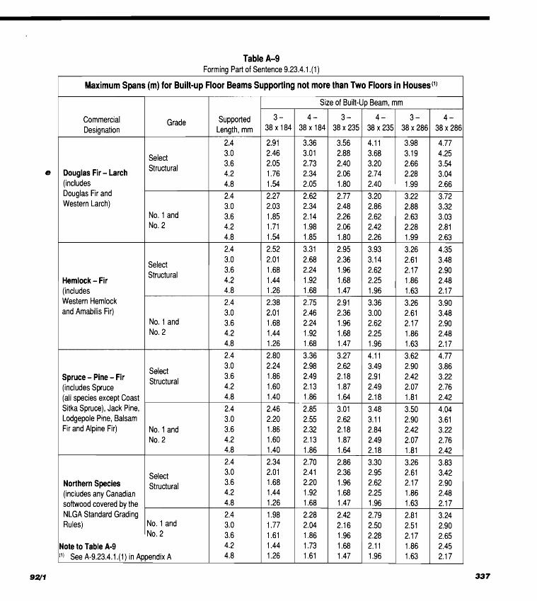
Table A-9 Forrr~iqg Part of Sentence 9.23.4.1 .(I)
1 Maximum Spans (m) for Built-up Floor Beams Supporting not more than Two Floors in Houses(l) I I Size of Built-up Beam, mm
Supported Length, mm
Select Structural Douglas Fir - Larch
(includes Douglas Fir and Western Larch)
No. 1 and No. 2
Select
Hemlock - Fir 1 Structural
(includes Western Hemlock and Amabilis Fir)
No. 1 and No. 2
Select Spruce - Pine - Fir Structural (includes Spruce (all species except Coast Sitka Spruce), Jack Pine, Lodgepole Pine, Balsam Fir and Alpine Fir) No. 1 and
Select Structural Northern Species
(includes any Canadian softwood covered by the NLGA Standard Grading Rules) No. 1 and 1 No. 2
Note to Table A-9 ( ' I See A-9.23.4.1 .(I) in Appendix A

Table A-1 0 Forming Part of Article 9.23.1 3.1 1.
TOP Member Size, mm
3 8 x 8 9
38x114
38x140
Bottom Member Size, mm
3 8 x 8 9
38x114
38x140
3 8 x 8 9
3Bx114
38x140
3 8 x 8 9
3 8 ~ 1 1 4
38x140
Clear Spans (m) between End Supports for No. 1 Grade Lumber
Maximum
Roof Slope
1 in 4.8 1 i n 4 1 in3 1 in 2.4
1 in 4.8 1 i n4 1 i n 3 1 in 2.4
1 in 4.8 1 i n4 1 i n 3 1 in 2.4
1 in 4.8 1 i n4 1 in 3 1 in 2.4
1 in 4.8 1 i n4 1 i n3 1 in 2.4
1 in 4.8 1 i n 4 1 i n3 1 in 2.4
1 in 4.8 lin4 1 in3 1 in 2.4
1 in 4.8 1 i n4 1 i n3 1 in 2.4
1 in 4.8 lin4 1 in3 1 in 2.4
1 .O
6.75 9.57 9.60 9.80
7.74 9.27 9.60 9.80
8.50 9.27 9.60 9.80
7.97 9.57
10.54 1 1.20
9.27 11.91 12.19 12.19
10.23 11.91 12.19 12.19
8.89 9.57
10.54 11.20
10.46 12.19 12.19 12.19
1 1.68 12.19 12.19 12.19
Fink Trusses No. 2 Grade Lumber
1 .O
5.84 8.02 8.91 9.1 1
6.75 8.58 8.91 9.1 1
7.44 8.58 8.91 9.1 1
6.95 8.02 8.96 9.57
8.12 10.31 10.74 10.99
9.01 10.31 10.74 10.99
7.39 8.02 8.96 9.57
9.22 10.33 11.50 12.19
10.33 12.19 12.19 12.19
Design Roof
1.5
4.87 8.12 8.83 9.04
5.74 8.53 8.83 9.04
6.35 8.53 8.83 9.04
5.91 8.66 9.75 9.90
6.98 10.23 10.64 10.89
7.79 10.23 10.64 10.89
6.73 8.66 9.75
10.49
7.97 11.12 12.19 12.19
8.96 12.19 12.19 12.19
Design Roof
1.5
4.01 7.13 7.69 7.87
4.85 7.36 7.69 7.87
5.46 7.36 7.69 7.87
5.02 7.16 8.20 8.91
6.04 9.24 9.24 9.49
6.78 9.47 9.47 9.49
5.81 7.1 6 8.20 8.91
6.95 9.24
10.54 1 1.45
7.84 10.82 1 1.30 1 1.60
Snow Load,
2.0
-
6.01 7.62 7.79
3.78 7.06 7.62 7.79
4.39 7.28 7.62 7.79
3.96 7.18 8.81 9.65
4.95 8.48 9.14 9.39
5.63 9.1 1 9.14 9.39
4.72 7.62 8.81 9.65
5.79 9.62
11.17 11.48
6.60 10.43 11.17 11.48
kPa
2.5
-
4.54 6.75 6.93 - 5.48 6.75 6.93 - 5.89 6.75 6.93 -
5.56 7.97 8.89
3.30 6.68 8.66 8.91
4.08 7.23 8.66 8.91 -
6.35 7.97 8.89
4.24 7.64 9.90
10.18
5.00 8.33 9.90
10.18
Snow Load,
2.0
-
5.18 6.60 6.78 -
6.14 6.60 6.78
3.47 6.29 6.60 6.78 -
6.24 7.31 8.1 0
4.08 7.44 8.48 8.71
4.77 8.05 8.48 8.71
3.86 6.24 7.31 8.10
4.92 8.02 9.42 9.98
5.68 9.22 9.67 9.98
kPa
2.5
-
3.78 5.84 6.01 - 4.67 5.84 6.01 -
5.08 5.84 6.01 - 4.77 6.57 7.41 -
5.79 7.49 7.74 -
6.29 7.49 7.74 -
5.48 6.57 7.41
3.27 6.68 8.45 9.44
4.14 7.31 9.16 9.44

can be found in the Commentary on Effects of Earthquakes in Chapter 4 of the Supplement to the NBC 1990.
A-4.1.9.D. Horizontal Force Factor, Sp. Lower values of Sp may be used for towers, chim- neys, smokestacks and penthouses when connected to or forming part of a building if the lower values can be proven by analysis. Information on the seismic design of towers, chimneys, smokestacks and penthouses can be found in the Commentary on Effects of Earthquakes in Chapter 4 of the Supple- ment to the NBC 1990.
A-4.1.9.E. Seismic Coefficient, C,. Lower values of Cp may be used for machinery, fixtures and equipment, pipes and tanks, when connected to or forming part of a building if the lower values can be proven by analysis. Information on the seismic design of machinery, fixtures and equipment, pipes and tanks can be found in the Commentary on Effects of Earthquakes in Chapter 4 of the Supple- ment to the NBC 1990.
A-4.1.9.1 422) Modal Coupling. Severe modal coupling may occur in symmetrical or nearly sym- metrical structures when the fundamental lateral and torsional periods are almost equal. Information on this phenomenon is given in the Commentary on Effects of Earthquakes in Chapter 4 of the Supple- ment to the NBC 1990.
A-4.1.9.1 .(25) Setbacks. A definition of setback together with a recommended design proce- dure for buildings having setbacks is contained in the Commentary on Effects of Earthquakes in Chapter 4 of the Supplement to the NBC 1990.
A-4.1.9.4.(3) Alternative Foundation Ties. Alternative methods of tying foundations together, such as a properly reinforced floor slab capable of resisting the required tension and compression forces, may be used. Passive soil pressure against buried pile caps may not be used to resist these forces.
A-4.1.9.4.(5) Seismic Lateral Pressures from Backfill or Natural Ground. Information on methods of computing the seismic lateral pres- sures from backfill or natural ground can be found in the Commentary on Effects of Earthquakes in Chap- ter 4 of the Supplement to the NBC 1990.
A-4.1.1 0.3. Loads on Firewalls. Information on loads on firewalls can be found in the Commen- tary on Structural Integrity of Firewalls in Chapter 4 of the Supplement to the NBC 1990.
A-4.1.1 0.5.(1) Dynamic Analyses of Floor Vibrations. Information on a dynamic analysis of floor vibrations from rhythmic activities can be found in the Commentary on Serviceability Criteria for Deflections and Vibrations in Chapter 4 of the Supplement to the NBC 1990.
A-4.2.2.1. Subsurface Investigation. Where acceptable information on subsurface conditions already exists, the investigation may not require further physical subsurface exploration or testing.
A-4.2.2.3.(1) Responsibilities of the Designer as Defined in Part 4. Under some situations, such as highly technical designs, it may be necessary for the "other suitably qualified person" to be someone responsible to the designer. In these cases the authority having jurisdiction may wish to order that the review be done by the designer.
A-4.2.4.1 .(I) Innovative Designs. It is important that innovative approaches to foundation design be carried out by a person especially qualified in the specific method applied and that the design gives a level of safety and performance at least equivalent to that provided for or implicit in the de- sign carried out by the methods referred to in Part 4. Provision must be made for monitoring the subse- quent performance of such structures so that the long term sufficiency of the design can be evaluated.
A-4.2.4.6.(1) Depth of Foundations. When adfreezing has occurred and subsequent freezing results in soil expansion beneath this area, the resulting uplift effect is sometimes referred to as frost jacking.
A heated building insulated to prevent heat loss through the foundation walls should be considered as an unheated structure unless the effect of the insulation is taken into account in determining the maximum depth of frost penetration.
A-4.2.5.1. Excavations. Information on excava- tions can be found in the Commentary on Founda- tions in Chapter 4 of the Supplement to the NBC 1990.

A-4.2.6.1. Shallow Foundations. Information on shallow foundations can be found in the Com- mentary on Foundations in Chapter 4 of the Supple- ment to the NBC 1990.
A-4.2.7.1. Deep Foundation Units. A deep foundation unit can be pre-manufactured or cast-in- place; it can be driven, jacked, jetted, screwed, bored or excavated; it can be of wood, concrete or steel or a combination thereof.
A-4.2.7.2.(1) Deep Foundations. Information on deep foundations can be found in the Commen- tary on Foundations in Chapter 4 of the Supplement to the NBC 1990.
A-4.2.7.2.(2) Load Testing of Piles. ASTM Dl 143, "Standard Method of Testing Piles Under Static Axial Compressive Load" defines routine load test procedures which have been used extensively.
A-4.3.3.1. Precast Concrete. CAN3-A23.3, "Design of Concrete Structures for Buildings" requires that precast concrete members be con- structed in plants conforming to CSA A251, "Qualifi- cation Code for the Manufacturers of Architectural and Structural Precast Concrete."
A-4.3.4.1. Welded Construction. Qualifica- tion for fabricators and erectors of welded construc-
e tion is found in Clause 23.3 of CAN/CSA-S16.1, "Limit States Design of Steel Structures."
A-4.3.6.1. Glass Design. Information on glass design can be found in the Commentary on Glass Design in Chapter 4 of the Supplement to the NBC 1990. A-5.5.2.1. Dampproofing and Waterproof- ing. For simple structures, requirements in Part 9 may be referred to as a guide in dampproofing and waterproofing below ground level. More complex structures may require additional provisions not con- tained in Part 9. A-5.5.3.1. Crawl Spaces. For simple struc- tures, requirements in Part 9 may be referred to as a guide for providing ground cover for crawl spaces. More complex structures may require additional pro- visions not contained in Part 9.
A-5.6.1.1. Materials. Part 3 contains additional requirements to regulate fire properties. Part 4 con- tains requirements to regulate the structural design.
A-5.7.1 .I. Installation. For simple structures, requirements in Part 9 may be referred to as a guide for the installation of exterior claddings, vapour barriers, thermal insulations, sheathing papers, flashings and fastening devices. More complex structures may require additional provisions not contained in Part 9.
A-5.7.1.2. Glass Design. Information on the design of glass can be found in the Commentary on Glass Design in Chapter 4 of the Supplement to the NBC 1990.
A-5.7.1.3.(3) Deformations in Building Components. Information on the effects of defor- mations in building components can be found in the Commentary on Effects of Deformations in Building Components in Chapter 4 of the Supplement to the NBC 1990.
A-6.2.2.5. NFPA Publications Pertaining to the Heating, Ventilating and Air-Condition- ing of Spaces Containing Hazardous Gases, Dusts or Liquids.
NFPA 30, Flammable and Combustible Liquids Code, NFPA 32, Drycleaning Plants, NFPA 33, Spray Application Using
Flammable and Combustible Materials, NFPA 34, Dipping and Coating Processes
Using Flammable or Combustible Liquids, NFPA 35, Manufacture of Organic Coatings, NFPA 36, Solvent Extraction Plants, NFPA 40, Storage and Handling of Cellulose Nitrate
Motion Picture Film, NFPA 50A, Gaseous Hydrogen Systems at Consumer
Sites, NFPA 50B, Liquefied Hydrogen Systems at Con-
sumer Sites, NFPA 51, Design and Installation of Oxygen-Fuel
Gas Systems for Welding and Cutting, NFPA 51A, Acetylene Cylinder Charging Plants, NFPA 61A, Fire and Dust Explosions in Facilities
Manufacturing and Handling Starch, NFPA 61B, Prevention of Fires and Explosions in
Grain Elevators and Facilities Handling Bulk Raw Agricultural Commodities,
NFPA 61C, Prevention of Fire and Dust Explosions in Feed Mills,
NFPA 65, Processing and Finishing of Aluminum, NFPA 68, Venting of Deflagrations,
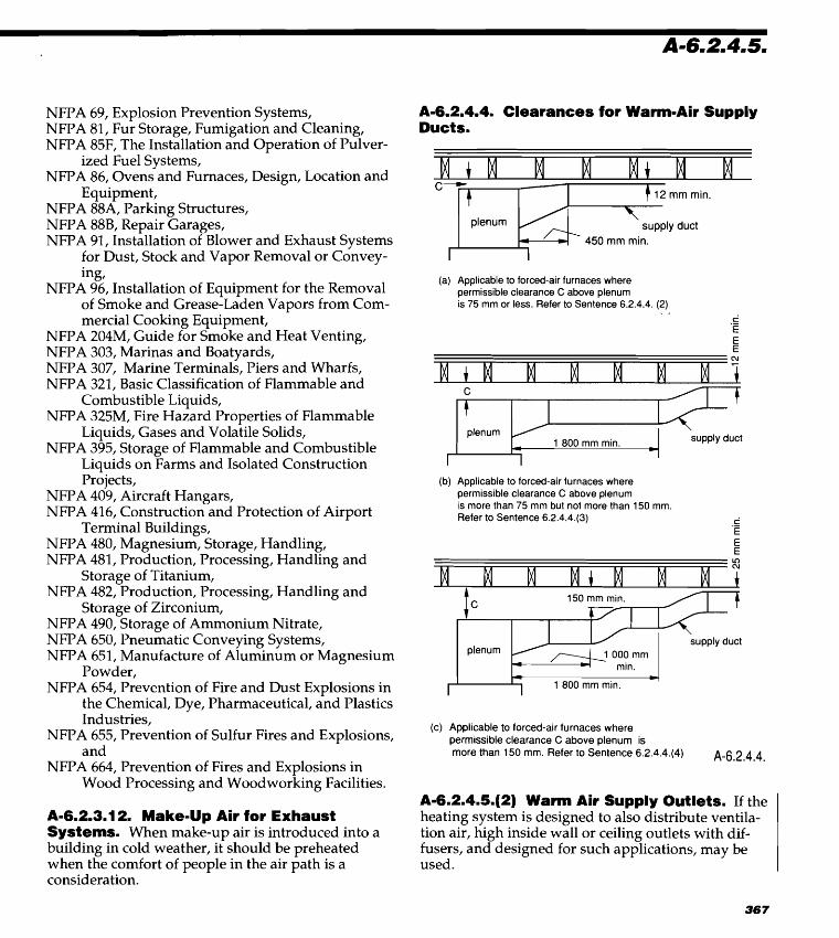
NFPA 69, Explosion Prevention Systems, NFPA 81, Fur Storage, Fumigation and Cleaning, NFPA 85F, The Installation and Operation of Pulver-
ized Fuel Systems, NFPA 86, Ovens and Furnaces, Design, Location and - Equipment, NFPA 88A, Parking Structures, NFPA 88B, Repair Garages, NFPA 91, Installation of Blower and Exhaust Systems
for Dust, Stock and Vapor Removal or Convey- ing,
NFPA 96, Installation of Equipment for the Removal - of Smoke and Grease-Laden Vapors from Com- mercial Cooking Equipment,
NFPA 204M, Guide for Smoke and Heat Venting, NFPA 303, Marinas and Boatyards, NFPA 307, Marine Terminals, Piers and Wharfs, NFPA 321, Basic Classification of Flammable and
Combustible Liquids, NFPA 325M, Fire Hazard Properties of Flammable
Liquids, Gases and Volatile Solids,
rl
NFPA 395, Storage of Flammable and Combustible Liquids on Farms and Isolated Construction Projects,
NFPA 409, Aircraft Hangars, NFPA 416, Construction and Protection of Airport
Terminal Buildings, NFPA 480, Magnesium, Storage, Handling, NFPA 481, Production, Processing, Handling and
Storage of Titanium, NFPA 482, Production, Processing, Handling and
Storage of Zirconium, ,- NFPA 490, Storage of Ammonium Nitrate,
NFPA 650, Pneumatic Conveying Systems, NFPA 651, Manufacture of Aluminum or Magnesium
Powder, NFPA 654, Prevention of Fire and Dust Explosions in
the Chemical, Dye, Pharmaceutical, and Plastics eb.b, Industries,
NFPA 655, Prevention of Sulfur Fires and Explosions, and
NFPA 664, Prevention of Fires and Explosions in Wood Processing and Woodworking Facilities.
x-.
A-6.2.3.1 2. Make-up Air for Exhaust Systems. When make-up air is introduced into a building in cold weather, it should be preheated when the comfort of people in the air path is a consideration.
A-6.2.4.4. Clearances for Warm-Air Supply Ducts.
I t 12 mm min.
plenum supply duct
450 mm min.
(a) Applicable to forced-air furnaces where permissible clearance C above plenum is 75 mm or less. Refer to Sentence 6.2.4.4. (2)
, , ti .- E E E
(b) Applicable to forced-air furnaces where permissible clearance C above plenum is more than 75 mm but not more than 150 mm. Refer to Sentence 6.2.4.4.(3) ti .-
E
150 mrn rnin.
I I I 1 800 mm min.
(c) Applicable to forced-air furnaces where permissible clearance C above plenum is more than 150 mm. Refer to Sentence 6.2.4.4.(4) A-6.2.4.4.
A-6.2.4.5.(2) Warm Air Supply Outlets. If the heating system is designed to also distribute ventila- tion air, high inside wall or ceiling outlets with dif- fusers, and designed for such applications, may be used.

A-6.2.9.2.(6) Temperature of Exposed A-8.2.2.1 2.(3) Purging of Tank. Guidance on e Piping. Normally piping carrying steam or high- methods of rendering inert tanks, piping and ma- temperature hot water at pressures above atmos- chinery reservoirs is available in NFPA 327, "Stan- pheric (corresponding temperature 100°C or above) dard Procedures for Cleaning or Safeguarding Small will be insulated to reduce heat losses as an economy Tanks and Containers." measure. Above a temperature of approximately 70°C, however, a bare pipe can cause a burn to human flesh coming in contact with the pipe. If pipes above this temperature are normally out of reach of all persons other than maintenance person- nel or are properly guarded, it would be expected that no insulation would be needed for public safety.
A-8.1.2.1. Application. The use of streets or public property and vehicular traffic during con- struction or demolition is normally controlled by regulations of authorities other than the building de- partment (i.e. police department).
A-8.2.2.1 .(I ) Demolition during Renovation. When renovation is taking place, only the portion of the building undergoing demolition is covered by this Subsection. The requirements for the portion undergoing construction are covered by Subsection 8.2.3.
A-8.2.2.1 42) Demolit ion. In certain buildings which do not pose an exposure hazard to other buildings, or in which there is little fire hazard to staff, such as in small buildings, the degree of appli- cation of this Subsection may be minimal. The degree of application should be determined in advance in conjunction with the authority having jurisdiction.
A-8.2.2.3.(2) Access for Fire Fighting. Fire fighting in storeys above the first requires prompt vertical movement by fire department personnel. Provision should be made for the use of elevators, hoists or lifts to assist such personnel in reaching upper storeys of the building.
A-8.2.2.5.' Standpipe System. During freezing conditions, the standpipe may be drained to prevent damage to the equipment. It is not antici- pated that hose will be available in the building being demolished, but that it will be brought to the relevant floor by the responding fire department.
A-8.2.3.1. Construction Sites. Construction sites can range from a large multi-storey building to small single-storey residences and may include additions or renovations to an existing building. The degree to which this Subsection should apply to each site should be determined in advance, as part of the fire safety plan for the construction site, taking into consideration such issues as the size of the project and condition of the site.
A-9.3.2.1. Grade Marking of Lumber. Lum- ber is generally grouped for marketing into the species combinations contained in the following table. The maximum allowable spans for those com- binations are listed in the span tables for joists, rafters and beams. Some species of lumber are also mar- keted individually. Since the allowable span for the northern species combination is based on the weakest species in the combination, the use of the span for this combination is permitted for any individual species not included in the Spruce-Pine-Fir, Douglas Fir-Larch, Hem-Fir combinations.
Facsimiles of typical grade marks of lumber associa- tions and grading agencies accredited by the Cana- dian Lumber Standards (CLS) Accreditation Board to grade mark lumber in Canada are shown in the following table. Accreditation by the CLS Accredita- tion Board applies to the inspection, grading and grade marking of lumber, including mill supervisory service, in accordance with CSA Standard 0141, "Softwood Lumber."
The grade mark of a CLS accredited agency on a piece of lumber indicates its assigned grade, species or species combination, moisture condition at the time of surfacing, the responsible grader or mill of origin and the CLS accredited agency under whose supervision the grading and marking was done.
Canadian lumber is graded to the NLGA Standard Grading Rules for Canadian Lumber, published by the National Lumber Grades Authority. The NLGA rules specify standard grade names and grade name
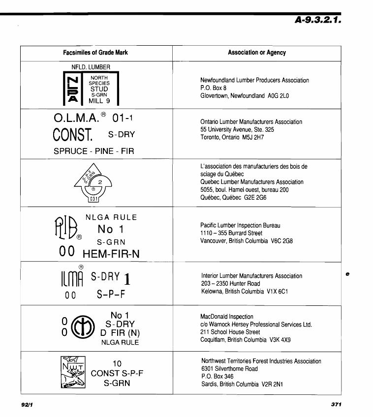
re.
Facsimiles of Grade Mark Association or Agency
NFLD. LUMBER
NORTH
MILL 9
Newfoundland Lumber Producers Association P.O. Box 8 Glovertown, Newfoundland AOG 2L0
SPRUCE - PINE - FIR
Ontario Lurr~ber Manufacturers Association 55 University Avenue, Ste. 325 Toronto, Ontario M5J 2H7
L'association des manufacturiers des bois de sciage du Quebec Quebec Lumber Manufacturers Association 5055, boul. Hamel ouest, bureau 200 Quebec, Quebec G2E 2G6
LGA R U L
No 1 S - G R N
EM-FIR-
Pacific Lumber Inspection Bureau 1 110 - 355 Burrard Street Vancouver, British Columbia V6C 2G8
O O S-P-F
Interior Lumber Manufacturers Association 203 - 2350 Hunter Road Kelowna, British Columbia V1X 6C1
No 1 S-DRY
D FIR (N) N L G A RULE
MacDonald lnspection c/o Warnock Hersey Professional Services Ltd. 21 1 School House Street Coquitlam, British Columbia V3K 4x9
10
COM::iP-F ,#A \.
Northwest Territories Forest Industries Association 6301 Silverthorne Road P.O. Box 346 Sardis, British Columbia V2R 2N1
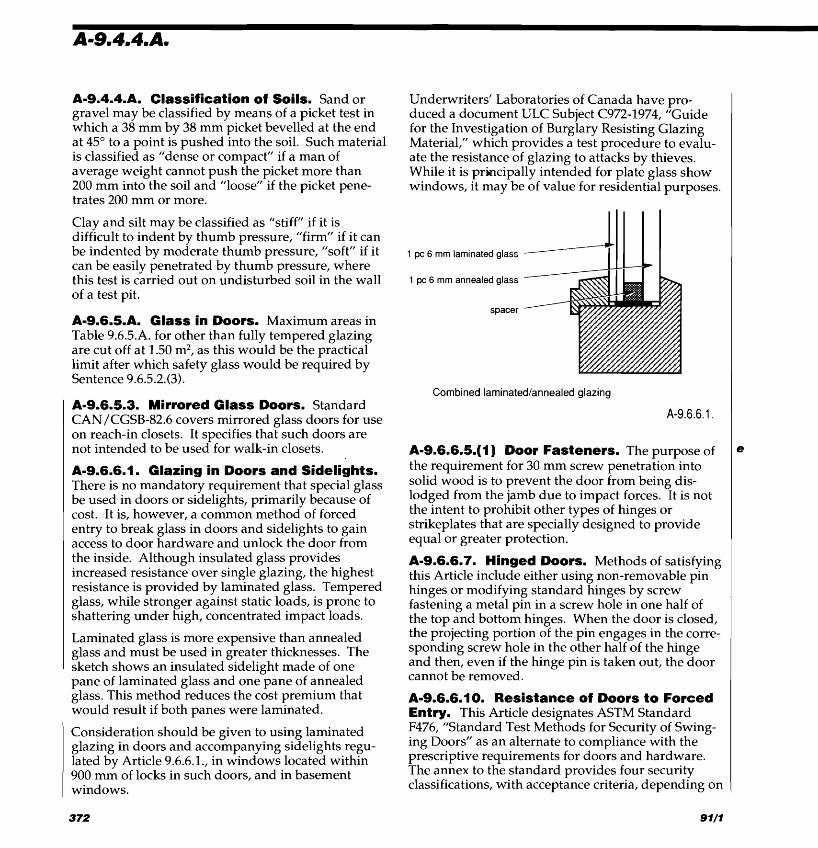
A-9.4.4.A. Classification of Soils. Sand or gravel may be classified by means of a picket test in which a 38 mm by 38 mm picket bevelled at the end at 45" to a point is pushed into the soil. Such material is classified as "dense or compact" if a man of average weight cannot push the picket more than 200 mm into the soil and "loose" if the picket pene- trates 200 mm or more.
Clay and silt may be classified as "stiff" if it is difficult to indent by thumb pressure, "firm" if it can be indented by moderate thumb pressure, "soft" if it can be easily penetrated by thumb pressure, where this test is carried out on undisturbed soil in the wall of a test pit.
A-9.6.5.A. Glass in Doors. Maximum areas in Table 9.6.5.A. for other than fully tempered glazing are cut off at 1.50 m2, as this would be the practical limit after which safety glass would be required by Sentence 9.6.5.2.(3).
A-9.6.5.3. Mirrored Glass Doors. Standard CAN/CGSB-82.6 covers mirrored glass doors for use on reach-in closets. It specifies that such doors are not intended to be used for walk-in closets.
A-9.6.6.1. Glazing in Doors and Sidelights. There is no mandatory requirement that special glass be used in doors or sidelights, primarily because of cost. It is, however, a common method of forced entry to break glass in doors and sidelights to gain access to door hardware and unlock the door from the inside. Although insulated glass provides increased resistance over single glazing, the highest resistance is provided by laminated glass. Tempered glass, while stronger against static loads, is prone to shattering under high, concentrated impact loads.
Laminated glass is more expensive than annealed glass and must be used in greater thicknesses. The sketch shows an insulated sidelight made of one pane of laminated glass and one pane of annealed glass. This method reduces the cost premium that would result if both panes were laminated.
Underwriters' Laboratories of Canada have pro- duced a document ULC Subject C972-1974, "Guide for the Investigation of Burglary Resisting Glazing Material," which provides a test procedure to evalu- ate the resistance of glazing to attacks by thieves. While it is principally intended for plate glass show windows, it may be of value for residential purposes.
1 pc 6 mm laminated glass
1 pc 6 mm annealed glass
spacer
Combined laminatedtannealed glazing
A-9.6.6.5.(1) Door Fasteners. The purpose of the requirement for 30 mm screw penetration into solid wood is to prevent the door from being dis- lodged from the jamb due to impact forces. It is not the intent to prohibit other types of hinges or strikeplates that are specially designed to provide equal or greater protection.
A-9.6.6.7. Hinged Doors. Methods of satisfying this Article include either using non-removable pin hinges or modifying standard hinges by screw fastening a metal pin in a screw hole in one half of the top and bottom hinges. When the door is closed, the projecting portion of the pin engages in the corre- sponding screw hole in the other half of the hinge and then, even if the hinge pin is taken out, the door cannot be removed.
A-9.6.6.1 0. Resistance of Doors to Forced Entry. This Article designates ASTM Standard F476, "Standard Test Methods for Security of Swing- ing Doors" as an alternate to compliance with the prescriptive requirements for doors and hardware. The annex to the standard provides four security classifications, with acceptance criteria, depending on
Consideration should be given to using laminated glazing in doors and accompanying sidelights regu- lated by Article 9.6.6.1., in windows located within 900 mm of locks in such doors, and in basement windows.
Dampers adjustable, 6.2.4.7. fire, used as closures (see Fire dampers) - in fireplaces, 9.22.6.1.
Dampproofing, 9.13 crawl spaces, 9.18.6.1. slabs, 9.13.1.2., 9.13.6. walls, 5.5.2.1., 9.13.1.2., 9.13.5., 9.20.13.10.
Dead end corridors (see Corridors) Dead loads (see Loads, structural) Debris (see Waste material) Decking, 3.1.5.3., 3.1.14., 9.26.9.1. Deep foundations
allowable loads, 4.2.7.3.(1), (2) damaged, 4.2.7.7. design, 4.2.7.2.(1) driving, handling and testing, 4.2.7.3.(5) installation, 4.2.7.6. load testing, 4.2.7.2.(2), (3) location and alignment, 4.2.7.4., 4.2.7.5. structural requirements, 4.2.7.3.
Definitions of words and phrases, 1.1.3., 4.1.4.1. Deflections, 4.1.1.5., 4.1.9.2., 9.4.3. Demolition sites
fire safety, 8.2.2. safety measures, Part 8
Design barrier-free (see Barrier-free design) loads (see Loads, structural) structural, Part 4,9.4
Designer, 1.1.3.2., 2.3.4.2., 2.3.4.4., 2.6.2.1., 2.6.3.1., 2.6.4.1., 4.1.1.2.(2), 4.1.3.3., 4.2.2.3.(1), 4.2.2.4.
Detectors heat, 3.2.4.11.(1), 3.2.4.16.(1), 9.10.17.3., 9.10.17.6. smoke, 3.2.4.12.(1), 3.2.4.13.(1), 9.10.17.3., 9.10.17.4.,
9.10.17.6., sprinklers installed in lieu of, 3.2.4.8.(5), 3.2.4.16.,
9.10.17.3.(3) Diffusers, air, 6.2.3.13.(2), 6.2.4.5.(6) Dining rooms, 9.5.4.
.- ~imensions, lumber, 3.1.4.6., 9.3.2.
Documents, referenced, 2.7 Doors and Doorways (see also Closures), 3.1.8.10.,
3.3.1.5., 3.3.1.10., 3.3.1.12., 3.7.3.3.(7), 3.7.3.8.(1),
9.6,9.9.6., 9.10.13. in a barrier-free path of travel, 3.7.3.3. between a dwelling unit and a garage, 9.10.13.15. in corridors, 3.1.8.11., 3.3.1.10., 3.3.1.12., 3.3.3.3.,
9.9.6., 9.10.13. direction of swing, 3.3.1.10.(1), 3.3.3.3.(3),
3.4.6.9.(5), 3.4.6.11., 9.9.6.5. in dwelling units, 3.1.13.2.(3), (5), 3.7.3.3.(2), 9.6,
9.9.6.5.(3), 9.9.6.8. egress from suites, 3.3.1.3.(8), 3.3.1.5., 9.9.6., 9.9.7.,
9.9.8., 9.9.9. exit, 3.4.5.1., 3.4.6.10., 9.9.6. exterior, 9.6.4., 9.6.6. in fire separations, 3.1.8.10. - 3.1.8.13., 3.1.8.15.,
3.3:3.6.(9), 3.3.3.7.(5), (9), (10),9.10.13. flame-spread rating, 3.1.13.2., 9.10.16.1. glass, 3.3.1.18., 3.4.1.8., 9.6.5., 9.9.4.3. hardware, 3.1.8.11. - 3.1.8.13., 3.3.1.18.(1), 3.3.2.6.,
3.3.3.6.(5), 3.4.6.15., 3.7.3.3.(4), 3.7.3.6.(1), 9.6.6., 9.9.6.3., 9.9.6.8. - 9.9.6.10.
height and width, 3.3.1.12., 3.3.3.5., 3.4.3.1.(1), 3.4.3.7., 9.6.3., 9.9.3.4., 9.9.6.4.
hold-open devices, 3.1.8.12,9.10.13.11. in institutional occupancies, 3.3.3. over landings, 9.8.4.2. in means of egress, 3.3.1.5.(1), 3.3.1.10.(1),
3.3.1.12.(1), 3.4.6.9.(5), 3.4.6.10., 9.9.6., 9.9.7., 9.10.13.
revolving, 3.4.6.14., 9.9.6.10. self-closing devices, 3.1.8.11.(1), 9.10.13.10.,
9.10.13.15.(1) to service rooms, 3.5.2.8., 9.10.13.12. sliding, 9.6.4.2. near stairs, 3.4.6.10.(1), 9.9.6.6. temperature rise limits, 3.1.6.1 1.
Door stops, 3.1.8.5.(3), 9.10.13.16. Downspouts, 9.14.6.4., 9.26.17.1. Draft stops, 3.2.8.7. Drainage, 9.14,9.16.3., 9.18.5. Drainage systems, plumbing, sanitary, Part 7,9.31 Drain, waste and vent piping, 3.1.9.4., 9.10.9.7. Drains
floor, 9.31.4.4. from noncombustible water closets, 3.1.9.4.(5),
9.10.9.7.(4) roof, 9.26.1 7.2.

Drawings (see Plans, specifications and calculations) Drinking Fountains, 3.7.3.15. Dry standpipes, 3.2.5.10.(2) Dry wells, 9.14.5.3. Ducts, 3.1.8.7., 3.1.8.8., 6.2.3., 6.2.4.
in ceiling spaces, 3.1.9.5., 3.5.4.5., 9.10.5.1.(4) clearances, 6.2.3.8., 6.2.4.4. combustible, 3.1.5.14.(1), 6.2.3.2. connecting 2 fire compartments, 3.1.8.7.(1),
9.10.13.13. connectors, 6.2.3.2., 6.2.4.3.(5) construction, 6.2.3.2., 6.2.4.2. coverings, 6.2.3.6., 9.10.16.12. exhaust, 6.2.3.10., 9.10.9.18., 9.32.3.5., 9.32.3.8. in fire rated assemblies, 3.1.9.2., 3.1.9.5.,
3.1.10.1.(4), 9.10.5.1., 9.10.9.6. fittings, 6.2.3.2., 6.2.4.2(2) galvanized, 6.2.4.2.(1) insulation, 3.1.5.14.(2), 6.2.3.6., 9.32.3.5. joints, 6.2.3.5., 6.2.4.3.(4) lining, 3.1.5.14.(2), 6.2.3.6., 6.2.4.8.(5), 9.10.16.12. materials, 6.2.3.2., 9.32.3.8., noncombustible, 3.1.8.8.(3), 3.1.8.8.(5) in noncombustible construction, 3.1.5.14.(1) penetrating fire stops, 3.1.11.7.(5), (6), 9.10.15.4. penetrating fire separations, 3.1.8.8., 3.1.9.1 .(I),
3.1.9.2., 9.10.9.6. return, 6.2.4.8. in or beneath slabs, 6.2.4.3.(8), (9), 6.2.4.6. supports, 6.2.4.343) supply, 6.2.3., 6.2.4.4., 6.2.4.5. trunk, 6.2.4.3.(6) underground, 6.2.3.7. ventilating, 9.32.3.8.
Duct systems, access openings, 6.2.3.3. Duct-type smoke detectors, 3.2.4.13.(1), 9.10.17.4. Dumbwaiter, design, construction, installation and
alteration, 3.5.5. Dwelling units, control of sound, 3.3.4.6., 9.1 1
e Earthquake design, 4.1.9., 9.20.15. analysis, 4.1.9.1. deflections, 4.1.9.2.
of foundations, 4.1.9.4. special provisions. 4.1.9.1 .(3)
Eave projections, 3.2.3.6., 9.10.14.13. Eave protection, 9.26.5. Egress from dwelling units, 3.3.4.4., 9.9.9. Electrical
conductors, protection of in high buildings, 3.2.6.9.(6), 3.2.6.14.
equipment vaults, 3.5.2.9. outlet boxes, 3.1.5.2.(1)(g), 3.1.9.1.(1), 3.1.9.2.,
3.1.9.3.(5), (6), 9.10.5.1., 9.10.9.6. raceways, 3.1.5.15.(1), 3.1.9.1.(1), 3.1.9.2., 9.10.9.6. wiring and equipment, 3.5.1.2., 6.2.1.4.(1), 9.34
Electromagnetic locking devices, 3.4.6.15.(4) Elevating devices, 3.7.2.1 .(I), 3.7.3.5. Elevators
arabic numerals, 3.5.5.2. in a barrier-free path of travel, 3.3.1.7.(1),
3.7.2.1.(1), 3.7.2.2., 3.7.3.5.(1) design, construction, installation and alteration,
3.5.5., 9.10.1.5. fire fighters', 3.2.6.2.(4), 3.2.6.9., 3.2.7.9.(1), (2),
3.5.3.1.(2) flame-spread rating, 3.1.13.7. in high buildings, 3.2.6.8., 3.2.7.9.(1), 3.5.5.1.(3) machinery rooms, 3.2.1.1.(1), 3.2.2.10.(1), 3.5.2.3.
Emergency lighting (see Lighting) Emergency power supply, 3.2.7.8., 3.2.7.9 ., 9.9.1 1.3. Entrance to buildings for disabled persons, 3.7.1.2.,
3.7.2.1., 3.7.3.3., 9.9.2.7. Equipment (see also Appliances and Service rooms)
cooking, 3.3.1.2.(2),6.2.2.6., 9.10.1.4. electrical installations, 6.2.1.4.(1), 9.34.1 .l. fire extinguishing, 8.2.2.4., 8.2.3.4. heating, ventilating and air-conditioning, Part 6,
9.32 and 9.33 loads on floors and roofs, 4.1.6.3., 4.1.6.7. odour removal, 6.2.2.4., 6.2.3.14. space cooling, 6.2.1.4.(1), 6.2.10., 9.33.1.1. space heating, Part 6,9.33.1.
Equivalents, 2.5 materials, 2.5.1. test standards, 2.5.3.
Escalators, design, construction, installation and alteration, 3.5.5., 9.10.1.5.
Evaporative cooling equipment, 6.2.3.15.

Sound resistance ratings of walls, floors and ceilings, 9.11.2.1.
Space frame, earthquake design, 4.1.9.1 .(9) Space heaters, 6.2.1.5., 9.33.1.2. Spans, wood, rafters, joists and beams, 9.23.4.
.I- Spatial separations between buildings, 3.2.3., 9.1 0.14. Special structures, 3.2.2.2. Specifications (see Standards, material) Sprinkler systems, 2.3.3.2., 3.1.4.6.(4), 3.1.5.11.(3), (4),
3.1.8.12.(2), 3.1.11.6., 3.1.13.6., 3.1.13.7.(2), 3.1.14.2.(2), 3.2.1.5.(1), 3.2.2., 3.2.3.11.(1), 3.2.3.15., 3.2.3.21.(1), 3.2.4.8.(5), 3.2.4.16., 3.2.5.3., 3.2.5.9.(1), 3.2.5.13., 3.2.5.14., 3.2.6.4.(1), 3.2.6.11., 3.2.8.2.(5), 3.2.8.6., 3.3.1.4.(1), 3.3.1.7.(1), 3.3.2.2.(2), 3.3.2.5.(1), 3.3.2.11.(1), 3.3.2.13.(1), 3.3.3.7.(1), 3.3.4.2.(2), 3.3.4.3., 3.5.2.9.(2), 3.5.3.3.(6), 9.9.8.1.(2), 9.9.8.2., 9.9.8.5.(2), 9.10.1.10., 9.10.8.2., 9.10.9.6.(8), 9.10.9.13.(2), 9.10.9.15., 9.10.10.6., 9.10.12.3., 9.10.13.8.(2), 9.10.14.6., 9.10.17.3.(3)
Stability, structural, 4.1.1.7.
C
Stages, theatrical, 3.3.2.13. Stairs (see also Escalators), 3.3.1.13., 3.3.4.8., 3.4.6., 9.8
cantilevered concrete, 9.8.9.1 ., 9.8.10. construction, wood, 9.8.9. curved, 3.3.1.15., 3.4.6.8., 9.8.5. dimensions, 3.4.3., 9.8.3. exit, 3.4.3.6.(3), 3.4.6., 9.8 fire stops required, 3.1.11.4.(1), 9.10.15.1.(3) handrails and guards, 3.3.4.8., 3.4.6.4., 3.4.6.5.,
3.4.7.6.(2), 9.8.7., 9.8.8. landings, 3.4.3.6.(3), 3.4.6.1.(2), 3.4.6.3.(2), 9.8.4. rise and run, 3.4.6.7., 9.8.3.1. slip-resistant finish, 3.4.6.1 .(I), 9.8.9.5. treads, 3.4.6.1., 3.4.6.7., 9.8.2.1., 9.8.3.1., 9.8.9.4.,
9.8.9.5. winders, 9.8.5.3.
-. Stairways, 3.3.1.13., 9.9.1.1. headroom clearance, 3.4.3.7., 9.8.3.4. lighting, 9.34.2.3. rooftop enclosures, 3.2.2.10. unenclosed between storeys, 3.2.8.2.(6) weather protection, 3.3.5.5.(2) - width, 3.4.3.1. - 3.4.3.5., 9.8.3.3.
standards material, 2.4,2.5
Standpipe and hose systems, 3.2.5.9., 9.10.1.10.
construction sites, 8.2.3.5., 9.10.20.9. demolition sites, 8.2.2.5. installation, 3.2.5.10., 8.2.3.5. where required, 3.2.5.9.(1)
Steel beams, 9.23.4.2. columns, 9.10.14.15., 9.17.3. design and construction, 4.3.4. fire protection, 3.2.2.3.(1), 9.10.7. in foundations, 4.2.3.7. - 4.2.3.10. siding, 9.27.12.1. studs, 9.24
Storage bins (see also Bins, refuse) 6.2.1 1. Storage garages, 3.2.1.2., 3.3.5.5.,6.2.2.3., 9.5.2.3.,
9.6.6.1.(1), 9.9.3.4.(2), 9.9.6.5.(4) 9.10.4.3., 9.10.9.16., 9.10.14.10., 9.10.17.8.
Storage lockers, 3.1.5.13. Storage of materials, 2.4.1.2., 3.3.1.2.(1), 9.10.1.8. Storage rooms
fire detectors, 3.2.4.10.(2), 9.10.17.5. fire separation, 3.3.4.3., 3.5.2.7., 9.10.10.6. wood storage lockers permitted, 3.1.5.13.
Storey, open-air, 3.2.1.5.(2), 9.10.14.10,9.10.17.8. Storeys below ground level, 3.2.2.1 1. (see also
Garages) Stoves, 6.2.1.5., 9.33.1.2. Strandboard, 3.1.1 1.7.(4), 3.2.3.16.(1)
for fire stopping, 3.1.11.7.(4), 3.2.3.16.(1), 9.10.15.3. interior finish, 9.29.9. roof sheathing, 9.3.2.4., 9.23.15. siding, 9.27.1 1. subflooring, 9.3.2.4., 9.23.14. tolerances, 9.3.2.7. underlay, 9.30.2. wall sheathing, 9.3.2.4., 9.23.16.
Streets, use of, 8.2.5. Stress reversal, 4.1.3.3. Structural fire protection, 3.2.2., 9.10.8. Structural loads and procedures, 4.1,9.4 Structural design, Part 4,9.4
limit states design, 4.1.4. working stress design, 4.1.3.
Structures, special, 3.2.2.2. Stucco, 9.28 Studs, wall, 9.23.10., 9.24 Subflooring, 9.23.14.

Suites, separation, 3.3.1 ., 9.10.9.13. Sumps, 6.2.3.15.(2), 9.14.5.2. Supply outlets, air, 6.2.4.5.
Tables for fire and sound resistance, 9.10.3.1., 9.11.2.1. Tape for joints in air duct systems, 6.2.3.5. Telephone shelves or counters, 3.7.3.14. Temperature
indoor design, 9.33.1.3. outdoor design, 6.2.1.2., 6.2.1.8., 9.33.1.3. supply air, 6.2.4.5.(7)
Tents, 3.1.6., 9.10.1.5. Termites, protection against, 4.3.1.3., 9.3.2.9.,
9.12.1.1.(2), 9.15.5.1.(2), 9.18.4.1. Tests
control of smoke movement in high buildings, 3.2.6.15.
elevator control, 3.5.5.1. (2) fire-protection rating, 3.1.8.4., 9.10.3.1. fire-resistance rating, 3.1.7.1 ., 9.10.3.1. flame-spread rating 3.1.12., 3.1.13.4.(1), 6.2.3.5.,
6.2.3.6., 9.10.3.2. load, 2.5.2.1., 4.2.4.1., 9.23.13.11.(8), 9.23.13.11.(9) roof covering, 3.1.1 5.1. smoke developed classification, 3.1.12. sound transmission, 9.11 .l. 1. verification of fire alarm systems, 3.2.4.5.(2)
Thermal barrier for foamed plastics, 3.1.5.1 1. Thermal insulation (see Insulation) Tile
drainage, 9.14.2. and 9.14.3. floor, 9.30.5.1., 9.30.6. wall, 9.29.10.
Timber (see Wood) Traffic control, 8.2.6. Transformer vaults, 9.10.1 -5. Travel distance, 3.3.1.6., 3.3.3.6.(11), 3.3.3.7.(6),
3.4.2.1.(2), 3.4.2.4., 9.9.7.5., 9.9.8.1., 9.9.8.2. Treads (see Stairs)
e Trusses, 9.4.2.2.(3), 9.23.13.11. Tubing for pneumatic controls, 3.1.5.2.(1) Turnstiles, 3.3.1.21 ., 9.9.5.4.
Underground walkways, 3.2.3.21 ., 3.2.7.3.(1) Underlay
beneath flooring, 9.30.2. beneath shakes, 9.26.10.2. beneath shingles, 9.26.6.
Unit masonry (see Masonry) Unprotected openings, 3.2.3., 9.1 0.14.
in floors, 3.2.8., 9.10.1.6. Unsprinklered areas, 3.1.1 1.5., 3.3.1.7. Unusual structures, 3.2.2.2.
Vacuum cleaning sys tems, 3.2.4.14., 9.10.1 7.7. Valves, supervision of water control in standpipe and
hose systems, 3.2.5.12. Vapour barriers, 5.2.1 ., 9.25.2.3., 9.25.6. Vapour diffusion control, 5.2,9.25.2.3., 9.25.6. Vault, 3.5.2.9. Vehicular passageway, 3.2.3.19.
flame-spread rating, 3.1.1 3.2. Vehicular traffic, 8.2.6. Ventilation, 3.3.1.19., 3.5.2.9.(5), 3.6.3., 6.2.1.1., 6.2.2.,
9.18.3. 9.19.1., 9.32 crawl space, 9.18.3. dwelling unit, 9.32 mechanical, 9.32.1 ., 9.32.3. natural, 9.32.1 ., 9.32.2. roof space, 9.19.1. storage garage, 6.2.2.3., 9.32.1.1 .(4)
Venting chimney, 6.3,9.21 chutes, 3.5.3.3.(3) explosion, 3.3.1.19.(2) for fire fighting in atriums, 3.2.8.8. for fire fighting in high buildings, 3.2.6.10.,
3.2.6.15. heating appliances, 6.2.1.4.(1)., 6.3.1.1., 9.21 soffits, 9.25.4.3.(4)
Vertical service space, 3.5.3., 9.10.1.1 1. flame-spread rating, 3.1.1 3.2.

Vestibules, 3.1.8.17.(1), 3.1.13.7., 3.2.8.4., 3.3.5.5.(1), 3.3.5.8., 3.4.6.9.(2), 3.7.3.3.(11)
e Vibrations, 4.1.1.6., 4.1.10.4., 4.1.10.5., 9.23.4.1.(2) Voice communication systems, 3.2.4.22., 3.2.6.1 3.,
3.2.7.8.(5)
Waferboard fire stopping, 3.1.11.7.(4), 3.2.3.16.(1), 9.10.15.3. interior finish, 9.29.9. roof sheathing, 9.3.2.4., 9.23.15. siding, 9.27.11. sub flooring, 9.3.2.4., 9.23.14. tolerances, 9.3.2.7. underlay, 9.30.2. wall sheathing, 9.3.2.4., 9.23.16.
Walkways exterior, in a barrier-free path of travel, 3.7.3.2. moving, 3.2.8.2.(5), 9.8.1.3. separation of buildings connected by, 3.2.3.20. underground, 3.2.3.21 ., 3.2.7.3.0)
Walls bracing, 9.23.18. combustible elements permitted, 3.1.5. exposed to adjoining roof, 3.2.3.15., 9.10.12.3. exterior, exposed to another wall, 3.2.3.14.,
9.10.12.4. external, meeting at a firewall, 3.1.10.6. fire-resistance rating, exterior, 3.1.7.2., 3.1.7.4.(3),
3.2.3.7., 3.2.3.10., 9.10.3.,9.10.14.7., 9.10.14.11. - 9.10.14.14.
fire-resistance rating, interior, 3.1.7.1 ., 3.1.7.4.(2), 9.10.3.
firewalls, 4.1.10.3., 9.10.11.3. foundation, 4.2,9.15.4. framing, 9.23.10. - 9.23.12., 9.24.2., 9.24.3.4. garage, 9.35.4. intersecting, anchorage, 9.20.1 1. loadbearing, 3.2.1.4.(2), 9.20.6.3., 9.23.1 0.1 .,
9.24.1.1 .(2) loads, 4.1.10.2. masonry, 9.20 party, 3.2.3.4., 9.10.11.1. plank frame, 9.4.1.2.
post and beam, 9.4.1.2. sheathing, 9.23.1 6.
Washroom facilities for disabled persons, 3.7.3.8. - 3.7.3.1 1.
Waste material, 8.2.7. Watch service, 8.2.2.14. Waterclosets, 3.6.4.2., 3.7.3.8., 3.7.3.9., 9.31.4.1. Watercloset rooms, 3.7.3.8., 9.5.7. Water heaters, service (see Service water heaters) Waterproofing and dampproofing, 5.5.2.1 ., 9.13,
9.20.13. Water supply, 9.31.3.
firefighting, 3.2.5.8. standpipes, 3.2.5.1 0.(3)
Water systems, 9.31.3. potable, 9.31.3.1.
Weep holes, 9.20.13.9. Wells, water, 9.14.5., 9.14.6.2. Wheelchair space, 3.7.2.1 .(2) Wind, water and vapour protection, Part 5 Wind loads, 4.1.8.
dynamic effects, 4.1 3.2. full and partial, 4.1.8.3. pressure differences due to, 4.1 B.4. specified, 4.1 3.1.
Winders, 9.8.5.3. Windows (see also Unprotected openings) 3.1.5.4.(2),
3.3.1.18., 3.4.6.5.(6), 3.6.2., 9.7,9.10.14.12.(2) access to exits, 3.3.1.18., 9.7.5. in exits, 3.1.8.16., 3.4.6.5.(6), 9.7.5., 9.9.4.5. factory-sealed double-glazed, 9.7.3.1., 9.7.4.1. in public spaces, 3.3.1.18.(5), 9.7.5. minimum glass area, 9.7.1.2. minimum glass thickness, 9.7.3.2. standard, 9.7.2.1.
Wired glass (see Glass) Wires and cables
electrical, 3.1.4.3.(1), 3.1.9.3., 3.2.6.9., 3.5.1.2., 3.5.4.3.(1), 9.34
in noncombustible construction, 3.1.5.17. Wood
cant strips, 3.1.5.343) columns, 3.1.4.6.(7), (8),9.10.14.15., 9.17.4., 9.35.4.2. design and construction, 3.1.4.1 .(I), 3.1.4.6., 4.3.1 .,
9.4,9.10.6.2., 9.23 dimensions, 3.1.4.6., 9.3.2.6. - 9.3.2.8. fire-retardant treated, 3.1.4.4.(1), 3.1.14.

flooring, 9.30.3., 9.30.4. floor supports, 3.1.4.6.(5), 9.23.8., 9.30.1.3. foundations, 4.2.3.1., 4.2.3.2., 9.15.1.3. preservative treatment, 4.2.3.2., 9.3.2.9. products, 9.3.2. roofs, 3.1.4.6.(4), (6), 3.1.14.1., 9.20.11.4. shingles and shakes, 9.26.9., 9.26.1 O., 9.27.7. siding, 9.27.6.
Working stress design, 4.1 -3. load combinations, 4.1.3.1. and 4.1.3.2. overturning and sliding, 4.1.3.4. stress reversal of, 4.1.3.3.
Workmanship, 2.6.4.
Yard, as access for fire fighters, 3.2.5.7.(1), 9.10.19.3.


![[XLS] · Web view400 630 630 400 630 990 990 630 630 630 630 990 990 990 990 990 990 400 400 990 630 990 630 630 400 990 990 990 990 990 630 630 990 990 630 630 990 990 990 990 990](https://static.fdocuments.net/doc/165x107/5af695027f8b9a5b1e8f4d8f/xls-view400-630-630-400-630-990-990-630-630-630-630-990-990-990-990-990-990-400.jpg)