D. GAMBIT TURBO FILE FORMAT - sharcnet.ca · D. GAMBIT TURBO FILE FORMAT Turbo files are ASCII text...
22
GAMBIT TURBO FILE FORMAT © 1998–2007 Fluent, Inc. All rights reserved. D-1 D. GAMBIT TURBO FILE FORMAT Turbo files are ASCII text files that contain numerical descriptions of turbo- machinery configurations. Such descriptions typically include the locations and connectivities of points and curves that describe the hub, casing, tip clear- ance, and blade profiles of the configuration. GAMBIT allows you to import either of two types of turbo files: • Pro/ENGINEER (IBL) • Native Pro/ENGINEER (IBL) files are generated by the Pro/ENGINEER CAD pack- age and are typically assigned the file extension of “.ibl”. Native files are structured in the native GAMBIT turbo-file format and are typically assigned the file extension “.tur”. This appendix describes the format of native GAMBIT turbo files. NOTE (1) : The GAMBIT turbo file format defines the sequence in which data records must appear in the file but does not constrain the formatting of data on any particular record. For example, on a record that contains the Cartesian coordinates of a single point, the coordinates can appear as strictly formatted (for example, 3F6.2) or as unformatted, separated by commas or blank characters. NOTE (2) : Any data record that begins with a forward slash (/) constitutes a comment record, and its data is ignored. Section D.1 describes the general structure of a GAMBIT native turbo file, including the sequence in which the records must appear in the file. Section D.2 shows an example turbo file.
Transcript of D. GAMBIT TURBO FILE FORMAT - sharcnet.ca · D. GAMBIT TURBO FILE FORMAT Turbo files are ASCII text...
GAMBIT TURBO FILE FORMAT
© 1998–2007 Fluent, Inc. All rights reserved. D-1
D. GAMBIT TURBO FILE FORMAT
Turbo files are ASCII text files that contain numerical descriptions of turbo-
machinery configurations. Such descriptions typically include the locations
and connectivities of points and curves that describe the hub, casing, tip clear-
ance, and blade profiles of the configuration. GAMBIT allows you to import
either of two types of turbo files:
• Pro/ENGINEER (IBL)
• Native
Pro/ENGINEER (IBL) files are generated by the Pro/ENGINEER CAD pack-
age and are typically assigned the file extension of “.ibl”. Native files are
structured in the native GAMBIT turbo-file format and are typically assigned
the file extension “.tur”. This appendix describes the format of native
GAMBIT turbo files.
� NOTE (1): The GAMBIT turbo file format defines the sequence in which data
records must appear in the file but does not constrain the formatting of data on
any particular record. For example, on a record that contains the Cartesian
coordinates of a single point, the coordinates can appear as strictly formatted
(for example, 3F6.2) or as unformatted, separated by commas or blank
characters.
� NOTE (2): Any data record that begins with a forward slash (/) constitutes a
comment record, and its data is ignored.
Section D.1 describes the general structure of a GAMBIT native turbo file,
including the sequence in which the records must appear in the file. Section
D.2 shows an example turbo file.

General Structure GAMBIT TURBO FILE FORMAT
D-2 © 1998–2007 Fluent, Inc. All rights reserved.
D.1 General Structure
The general structure of a GAMBIT turbo file consists of three sections:
• Header information
• Hub, casing, and tip-clearance data
• Blade data
Header information describes the turbo file version number, the rotational
axis, and the coordinate system type used to specify point locations. Hub,
casing, and tip-clearance data describe the inner and outer boundaries of the
turbo volume (with respect to the axis of revolution). Blade data describes the
shapes of the blades and splitters (optional) that comprise the internal compo-
nents of the turbo volume.
D.1.1 Header Information
The first major section of the turbo file consists of three non-comment data
records that contain header information. Each record appears only once in the
turbo file.
Header information in a GAMBIT turbo file consists of the following items:
• File version number
• Rotational axis
• Coordinate system type
The following subsections describe the items listed above.
GAMBIT TURBO FILE FORMAT General Structure
© 1998–2007 Fluent, Inc. All rights reserved. D-3
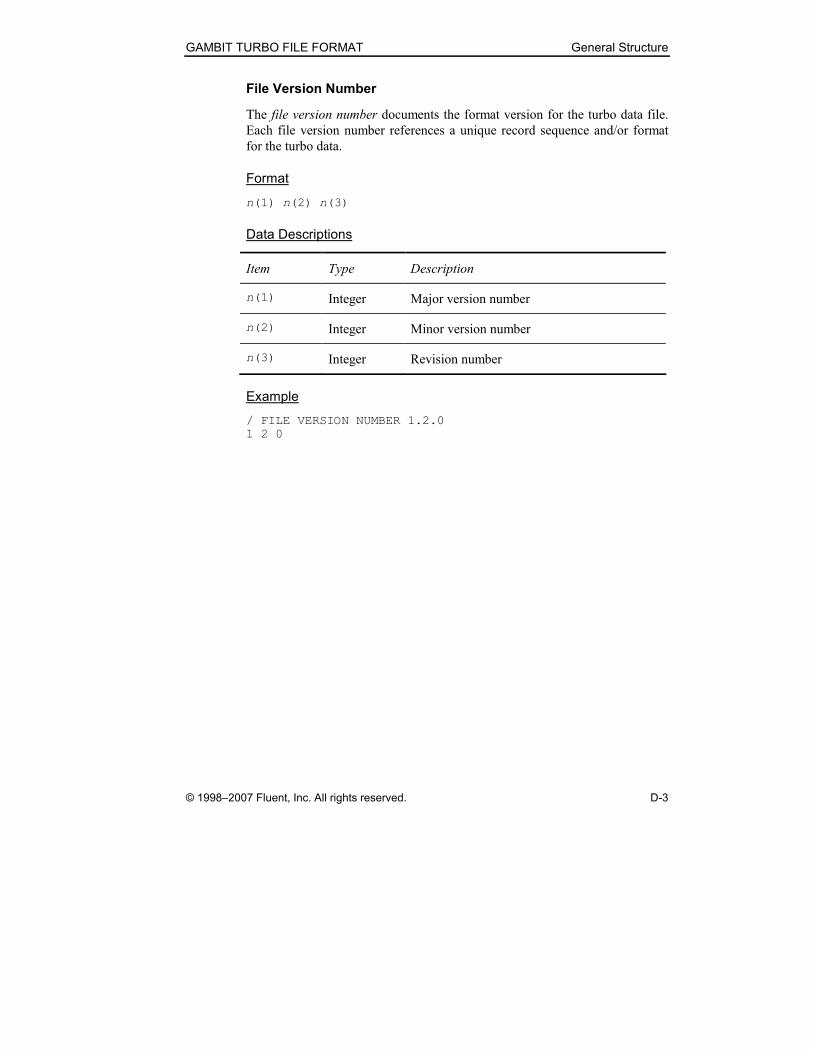
File Version Number
The file version number documents the format version for the turbo data file.
Each file version number references a unique record sequence and/or format
for the turbo data.
Format
n(1) n(2) n(3)
Data Descriptions
Item Type Description
n(1) Integer Major version number
n(2) Integer Minor version number
n(3) Integer Revision number
Example
/ FILE VERSION NUMBER 1.2.0
1 2 0
General Structure GAMBIT TURBO FILE FORMAT
D-4 © 1998–2007 Fluent, Inc. All rights reserved.
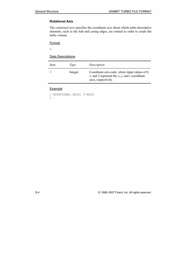
Rotational Axis
The rotational axis specifies the coordinate axis about which turbo descriptive
elements, such as the hub and casing edges, are rotated in order to create the
turbo volume.
Format
n
Data Descriptions
Item Type Description
n Integer Coordinate axis code, where input values of 0,
1, and 2 represent the x, y, and z coordinate
axes, respectively.
Example
/ ROTATIONAL AXIS: Y-AXIS
1
GAMBIT TURBO FILE FORMAT General Structure
© 1998–2007 Fluent, Inc. All rights reserved. D-5
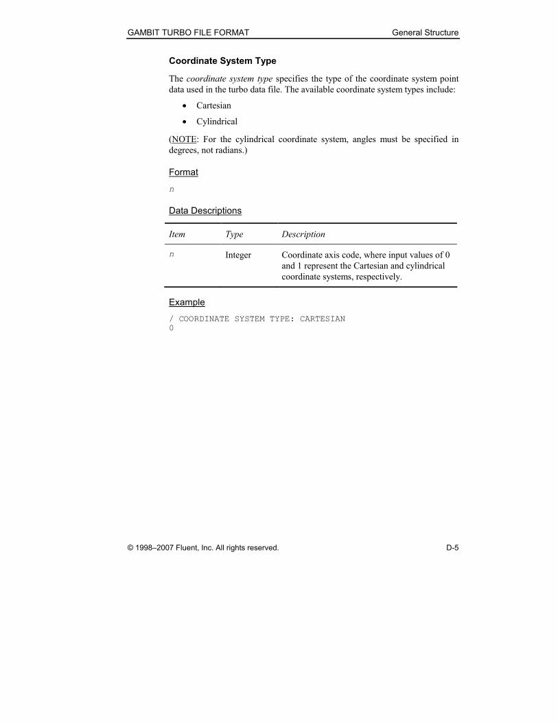
Coordinate System Type
The coordinate system type specifies the type of the coordinate system point
data used in the turbo data file. The available coordinate system types include:
• Cartesian
• Cylindrical
(NOTE: For the cylindrical coordinate system, angles must be specified in
degrees, not radians.)
Format
n
Data Descriptions
Item Type Description
n Integer Coordinate axis code, where input values of 0
and 1 represent the Cartesian and cylindrical
coordinate systems, respectively.
Example
/ COORDINATE SYSTEM TYPE: CARTESIAN
0
General Structure GAMBIT TURBO FILE FORMAT
D-6 © 1998–2007 Fluent, Inc. All rights reserved.
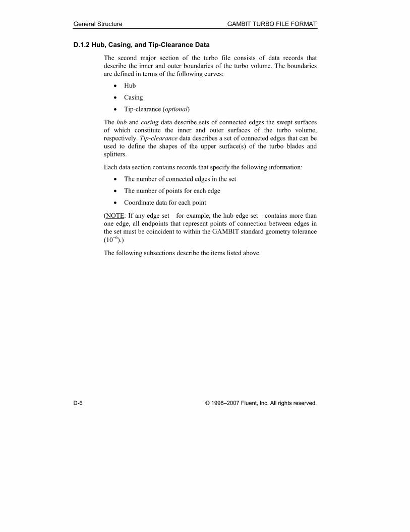
D.1.2 Hub, Casing, and Tip-Clearance Data
The second major section of the turbo file consists of data records that
describe the inner and outer boundaries of the turbo volume. The boundaries
are defined in terms of the following curves:
• Hub
• Casing
• Tip-clearance (optional)
The hub and casing data describe sets of connected edges the swept surfaces
of which constitute the inner and outer surfaces of the turbo volume,
respectively. Tip-clearance data describes a set of connected edges that can be
used to define the shapes of the upper surface(s) of the turbo blades and
splitters.
Each data section contains records that specify the following information:
• The number of connected edges in the set
• The number of points for each edge
• Coordinate data for each point
(NOTE: If any edge set—for example, the hub edge set—contains more than
one edge, all endpoints that represent points of connection between edges in
the set must be coincident to within the GAMBIT standard geometry tolerance
(10−6).)
The following subsections describe the items listed above.
GAMBIT TURBO FILE FORMAT General Structure
© 1998–2007 Fluent, Inc. All rights reserved. D-7
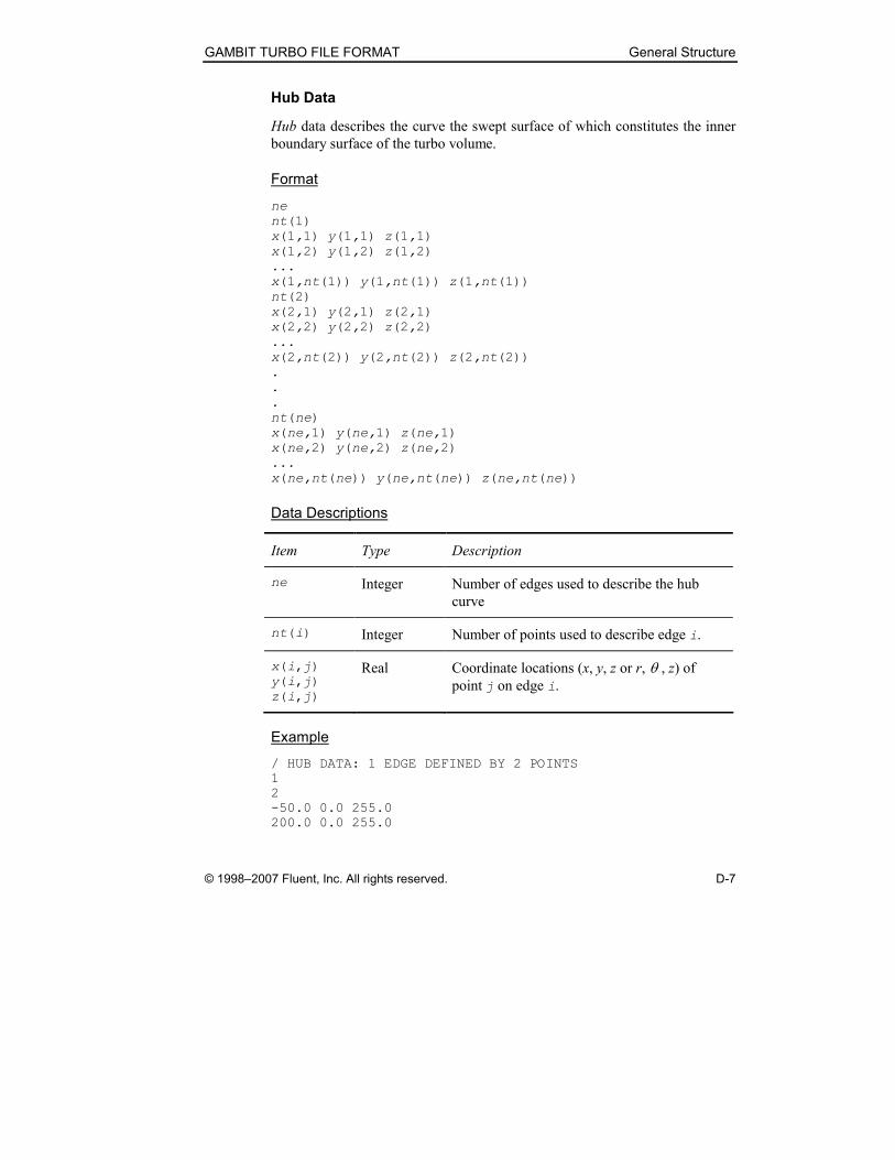
Hub Data
Hub data describes the curve the swept surface of which constitutes the inner
boundary surface of the turbo volume.
Format
ne
nt(1)
x(1,1) y(1,1) z(1,1)
x(1,2) y(1,2) z(1,2)
...
x(1,nt(1)) y(1,nt(1)) z(1,nt(1))
nt(2)
x(2,1) y(2,1) z(2,1)
x(2,2) y(2,2) z(2,2)
...
x(2,nt(2)) y(2,nt(2)) z(2,nt(2))
.
.
.
nt(ne)
x(ne,1) y(ne,1) z(ne,1)
x(ne,2) y(ne,2) z(ne,2)
...
x(ne,nt(ne)) y(ne,nt(ne)) z(ne,nt(ne))
Data Descriptions
Item Type Description
ne Integer Number of edges used to describe the hub
curve
nt(i) Integer Number of points used to describe edge i.
x(i,j)
y(i,j)
z(i,j)
Real Coordinate locations (x, y, z or r, θ , z) of
point j on edge i.
Example
/ HUB DATA: 1 EDGE DEFINED BY 2 POINTS
1
2
-50.0 0.0 255.0
200.0 0.0 255.0
General Structure GAMBIT TURBO FILE FORMAT
D-8 © 1998–2007 Fluent, Inc. All rights reserved.
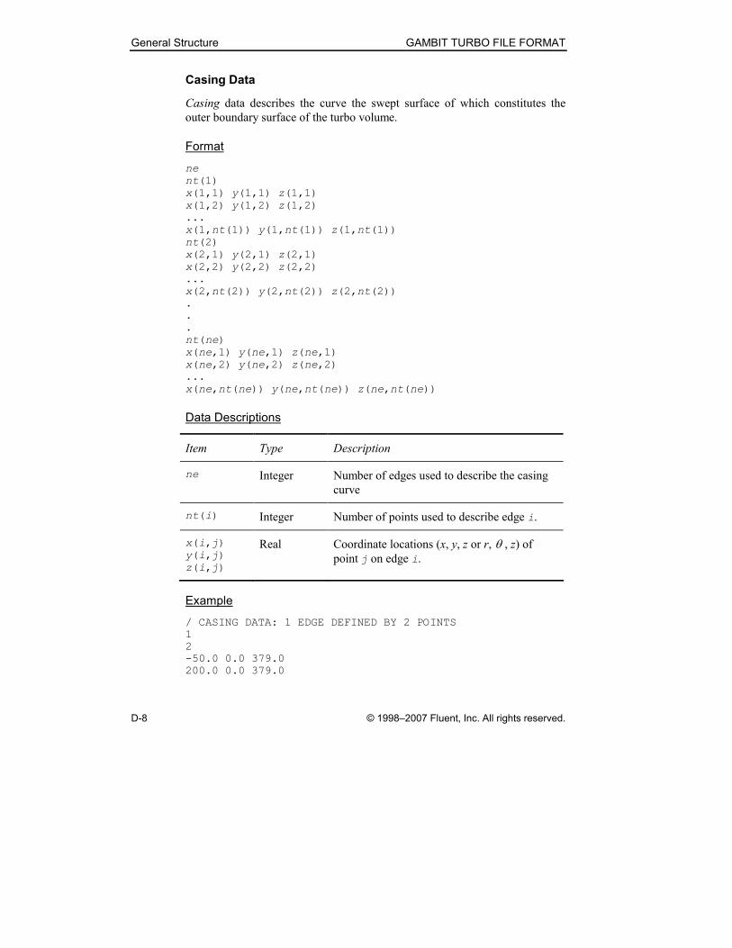
Casing Data
Casing data describes the curve the swept surface of which constitutes the
outer boundary surface of the turbo volume.
Format
ne
nt(1)
x(1,1) y(1,1) z(1,1)
x(1,2) y(1,2) z(1,2)
...
x(1,nt(1)) y(1,nt(1)) z(1,nt(1))
nt(2)
x(2,1) y(2,1) z(2,1)
x(2,2) y(2,2) z(2,2)
...
x(2,nt(2)) y(2,nt(2)) z(2,nt(2))
.
.
.
nt(ne)
x(ne,1) y(ne,1) z(ne,1)
x(ne,2) y(ne,2) z(ne,2)
...
x(ne,nt(ne)) y(ne,nt(ne)) z(ne,nt(ne))
Data Descriptions
Item Type Description
ne Integer Number of edges used to describe the casing
curve
nt(i) Integer Number of points used to describe edge i.
x(i,j)
y(i,j)
z(i,j)
Real Coordinate locations (x, y, z or r, θ , z) of
point j on edge i.
Example
/ CASING DATA: 1 EDGE DEFINED BY 2 POINTS
1
2
-50.0 0.0 379.0
200.0 0.0 379.0
GAMBIT TURBO FILE FORMAT General Structure
© 1998–2007 Fluent, Inc. All rights reserved. D-9
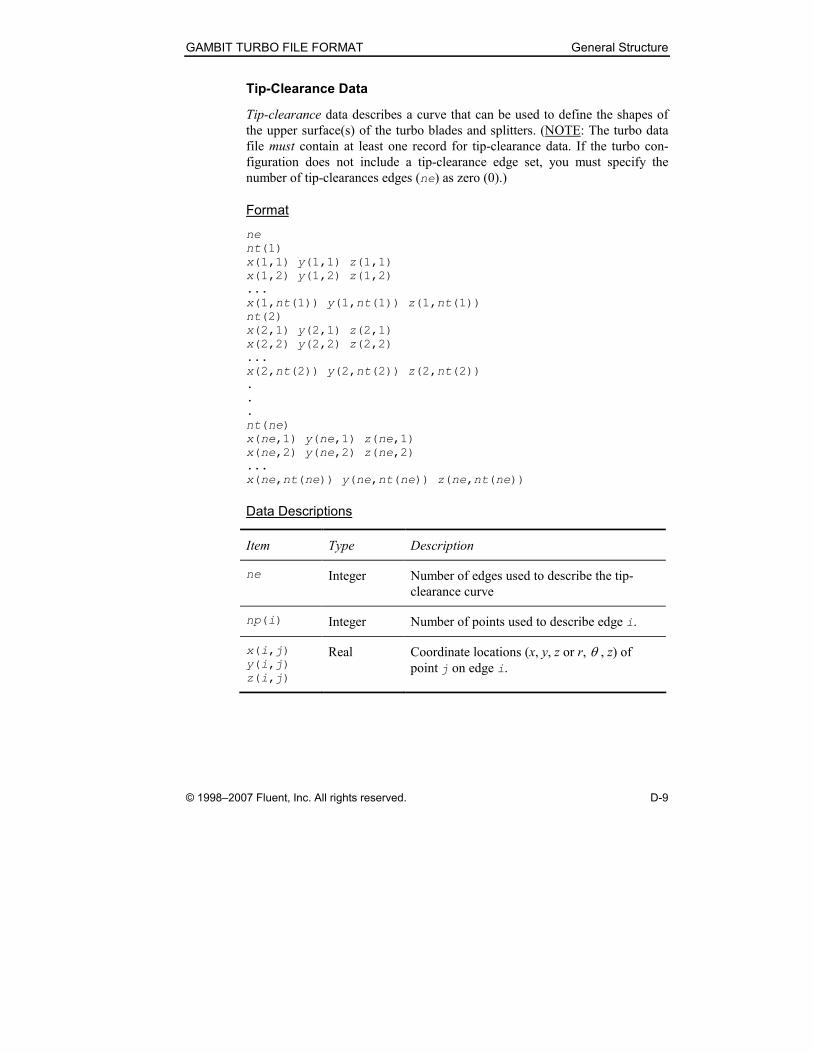
Tip-Clearance Data
Tip-clearance data describes a curve that can be used to define the shapes of
the upper surface(s) of the turbo blades and splitters. (NOTE: The turbo data
file must contain at least one record for tip-clearance data. If the turbo con-
figuration does not include a tip-clearance edge set, you must specify the
number of tip-clearances edges (ne) as zero (0).)
Format
ne
nt(1)
x(1,1) y(1,1) z(1,1)
x(1,2) y(1,2) z(1,2)
...
x(1,nt(1)) y(1,nt(1)) z(1,nt(1))
nt(2)
x(2,1) y(2,1) z(2,1)
x(2,2) y(2,2) z(2,2)
...
x(2,nt(2)) y(2,nt(2)) z(2,nt(2))
.
.
.
nt(ne)
x(ne,1) y(ne,1) z(ne,1)
x(ne,2) y(ne,2) z(ne,2)
...
x(ne,nt(ne)) y(ne,nt(ne)) z(ne,nt(ne))
Data Descriptions
Item Type Description
ne Integer Number of edges used to describe the tip-
clearance curve
np(i) Integer Number of points used to describe edge i.
x(i,j)
y(i,j)
z(i,j)
Real Coordinate locations (x, y, z or r, θ , z) of
point j on edge i.

General Structure GAMBIT TURBO FILE FORMAT
D-10 © 1998–2007 Fluent, Inc. All rights reserved.
Example
/ TIP-CLEARANCE DATA: 1 EDGE DEFINED BY 2 POINTS
1
2
-50.0 0.0 360.0
200.0 0.0 300.0
GAMBIT TURBO FILE FORMAT General Structure
© 1998–2007 Fluent, Inc. All rights reserved. D-11
D.1.3 Blade Data
The third major section of the turbo file consists of data records that describe
the blade and (optionally) splitter. Turbo blade data consists of the following
items:
• Number of blades
• Number of profiles and sides
• Profile edge continuity
• Pressure- and suction-side data
The number-of-blades data record specifies whether the turbo configuration
consists of a single blade only or of a blade-and-splitter combination and
appears only once in the set of blade data records. The other data records listed
above are repeated for each blade (or splitter). They include the number of
profiles (that is, sets of edges describing the blade cross section), the profile
edge continuity, as well as the edge data that describes the pressure and
suction sides of each blade.
General Structure GAMBIT TURBO FILE FORMAT
D-12 © 1998–2007 Fluent, Inc. All rights reserved.
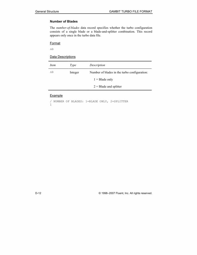
Number of Blades
The number-of-blades data record specifies whether the turbo configuration
consists of a single blade or a blade-and-splitter combination. This record
appears only once in the turbo data file.
Format
nb
Data Descriptions
Item Type Description
nb Integer Number of blades in the turbo configuration:
1 = Blade only
2 = Blade and splitter
Example
/ NUMBER OF BLADES: 1=BLADE ONLY, 2=SPLITTER
1
GAMBIT TURBO FILE FORMAT General Structure
© 1998–2007 Fluent, Inc. All rights reserved. D-13
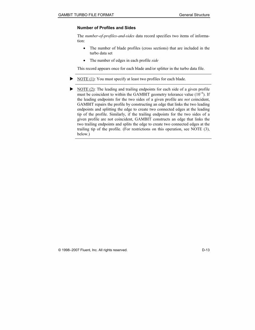
Number of Profiles and Sides
The number-of-profiles-and-sides data record specifies two items of informa-
tion:
• The number of blade profiles (cross sections) that are included in the
turbo data set
• The number of edges in each profile side
This record appears once for each blade and/or splitter in the turbo data file.
� NOTE (1): You must specify at least two profiles for each blade.
� NOTE (2): The leading and trailing endpoints for each side of a given profile
must be coincident to within the GAMBIT geometry tolerance value (10−6). If
the leading endpoints for the two sides of a given profile are not coincident,
GAMBIT repairs the profile by constructing an edge that links the two leading
endpoints and splitting the edge to create two connected edges at the leading
tip of the profile. Similarly, if the trailing endpoints for the two sides of a
given profile are not coincident, GAMBIT constructs an edge that links the
two trailing endpoints and splits the edge to create two connected edges at the
trailing tip of the profile. (For restrictions on this operation, see NOTE (3),
below.)
General Structure GAMBIT TURBO FILE FORMAT
D-14 © 1998–2007 Fluent, Inc. All rights reserved.
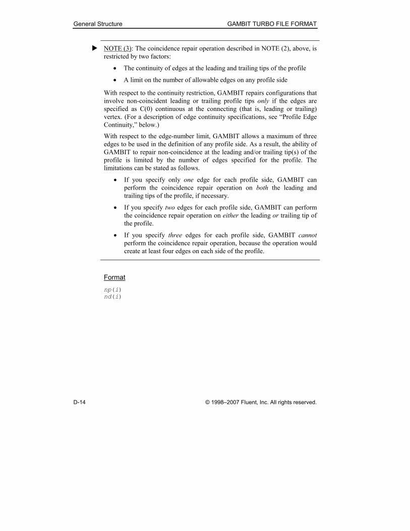
� NOTE (3): The coincidence repair operation described in NOTE (2), above, is
restricted by two factors:
• The continuity of edges at the leading and trailing tips of the profile
• A limit on the number of allowable edges on any profile side
With respect to the continuity restriction, GAMBIT repairs configurations that
involve non-coincident leading or trailing profile tips only if the edges are
specified as C(0) continuous at the connecting (that is, leading or trailing)
vertex. (For a description of edge continuity specifications, see “Profile Edge
Continuity,” below.)
With respect to the edge-number limit, GAMBIT allows a maximum of three
edges to be used in the definition of any profile side. As a result, the ability of
GAMBIT to repair non-coincidence at the leading and/or trailing tip(s) of the
profile is limited by the number of edges specified for the profile. The
limitations can be stated as follows.
• If you specify only one edge for each profile side, GAMBIT can
perform the coincidence repair operation on both the leading and
trailing tips of the profile, if necessary.
• If you specify two edges for each profile side, GAMBIT can perform
the coincidence repair operation on either the leading or trailing tip of
the profile.
• If you specify three edges for each profile side, GAMBIT cannot
perform the coincidence repair operation, because the operation would
create at least four edges on each side of the profile.
Format
np(i)
nd(i)
GAMBIT TURBO FILE FORMAT General Structure
© 1998–2007 Fluent, Inc. All rights reserved. D-15
Data Descriptions
Item Type Description
np(i) Integer Number of profiles used to describe blade i.
(NOTE: np(i) ≥ 2)
nd(i) Integer Number of edges per side used to describe
each profile for blade i.
(NOTE: nd(i) = 1, 2, or 3.)
Example
/ NUMBER OF PROFILES FOR BLADE 1
2
/ NUMBER OF EDGES PER SIDE FOR EACH PROFILE
2
General Structure GAMBIT TURBO FILE FORMAT
D-16 © 1998–2007 Fluent, Inc. All rights reserved.
Profile Edge Continuity
Profile edge continuity defines the continuity between all edges used to
describe blade i. This record appears once for each blade and/or splitter in the
turbo data file.
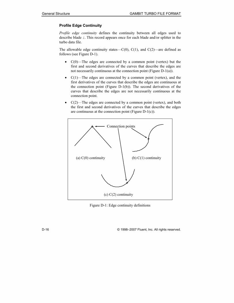
The allowable edge continuity states—C(0), C(1), and C(2)—are defined as
follows (see Figure D-1).
• C(0)—The edges are connected by a common point (vertex) but the
first and second derivatives of the curves that describe the edges are
not necessarily continuous at the connection point (Figure D-1(a)).
• C(1)—The edges are connected by a common point (vertex), and the
first derivatives of the curves that describe the edges are continuous at
the connection point (Figure D-1(b)). The second derivatives of the
curves that describe the edges are not necessarily continuous at the
connection point.
• C(2)—The edges are connected by a common point (vertex), and both
the first and second derivatives of the curves that describe the edges
are continuous at the connection point (Figure D-1(c)).
(a) C(0) continuity (b) C(1) continuity
(c) C(2) continuity
Connection points
Figure D-1: Edge continuity definitions
GAMBIT TURBO FILE FORMAT General Structure
© 1998–2007 Fluent, Inc. All rights reserved. D-17
� NOTE: Profile edge continuity defines continuity between adjacent edges as
observed at their connecting endpoints. Therefore, to fully specify profile edge
continuity, you must specify continuity at the leading and trailing tips of the
profile and at all intermediate points of connection between the edges used to
define the profile. For example, if a profile includes only one edge per side,
you must specify two continuity values—one for the leading tip of the profile
and one for the trailing tip of the profile. If a profile includes two edges per
side, you must specify three continuity entries—one each for the profile
leading and trailing tips and one for the point of connection between the two
edges that define either side of the profile.
Format
pc(i,1) pc(i,2), ..., pc(i,nd(i+1))
Data Descriptions
Item Type Description
pc(i) Integer Profile continuity for all edges used to
describe blade i. (NOTE: Allowable values
include 0, 1, and 2—corresponding to C(0),
C(1), and C(2) continuity, respectively.)
nd(i) Integer Number of edges per side used to describe
each profile for blade i (see “Number of
Profiles and Sides,” above).
Example
/ PROFILE EDGE CONTINUITY
2 2
General Structure GAMBIT TURBO FILE FORMAT
D-18 © 1998–2007 Fluent, Inc. All rights reserved.
Pressure- and Suction-Side Data
Pressure- and suction-side data records contain point data that define the
edges used to describe the pressure and suction sides, respectively, of the
blade and splitter. The point data and record sequences must be organized
according to the following rules.
• Point data for each edge must be ordered such that it describes the edge
from its leading endpoint to its trailing endpoint.
• The complete description of each profile consists of all point data that
describes the pressure side of the profile followed by all point data that
describes the suction side of the profile.
• The data records must be ordered such that descriptions of the profiles
appear in spanwise order, from the hub to the casing (see the example
turbo data file described in Section D.2, below).
Format
nt(k,1)
x(k,1,1) y(k,1,1) z(k,1,1)
x(k,1,2) y(k,1,2) z(k,1,2)
...
x(k,1,nt(k,1)) y(k,1,nt(k,1)) z(k,1,nt(k,1))
Data Descriptions
Item Type Description
nt(k,i) Integer Number of points used to describe pressure-
side edge i of profile k.
x(k,i,j)
y(k,i,j)
z(k,i,j)
Real Coordinate locations (x, y, z or r, θ , z) of
point j on edge i for profile k.
GAMBIT TURBO FILE FORMAT General Structure
© 1998–2007 Fluent, Inc. All rights reserved. D-19
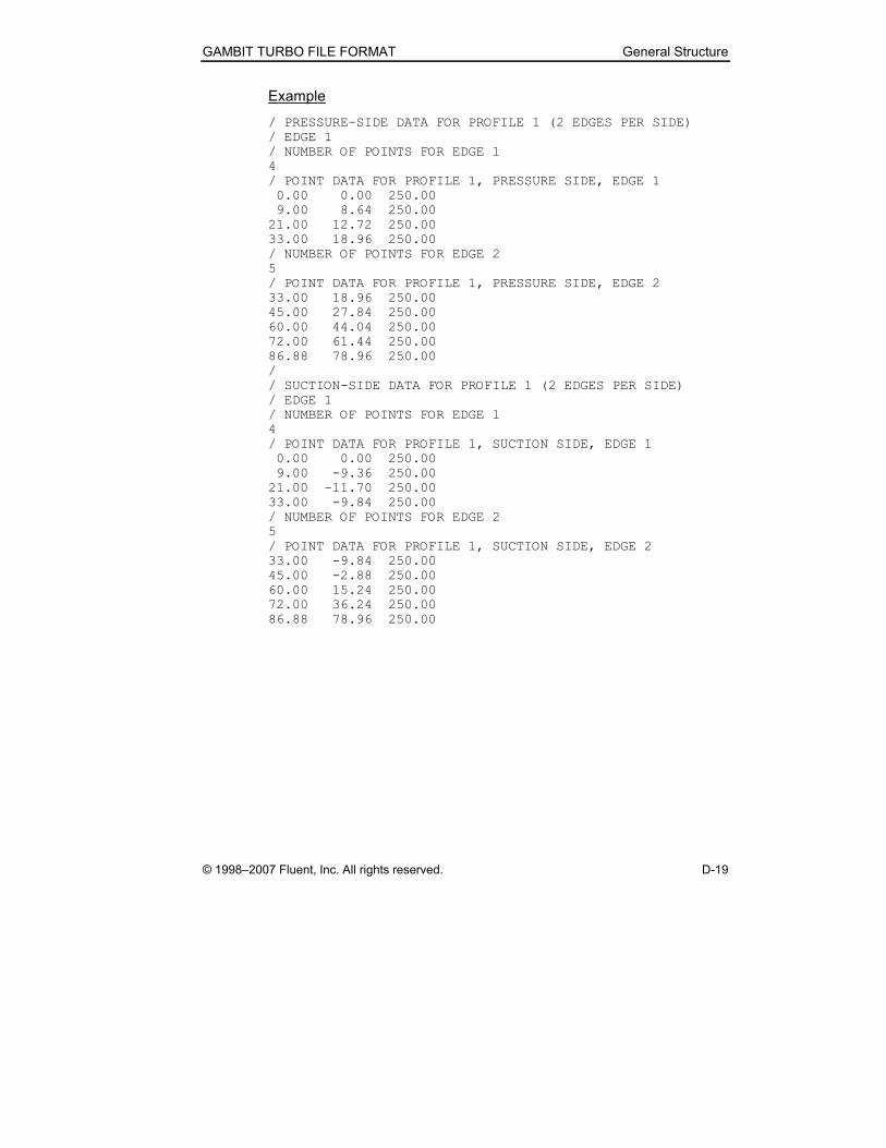
Example
/ PRESSURE-SIDE DATA FOR PROFILE 1 (2 EDGES PER SIDE)
/ EDGE 1
/ NUMBER OF POINTS FOR EDGE 1
4
/ POINT DATA FOR PROFILE 1, PRESSURE SIDE, EDGE 1
0.00 0.00 250.00
9.00 8.64 250.00
21.00 12.72 250.00
33.00 18.96 250.00
/ NUMBER OF POINTS FOR EDGE 2
5
/ POINT DATA FOR PROFILE 1, PRESSURE SIDE, EDGE 2
33.00 18.96 250.00
45.00 27.84 250.00
60.00 44.04 250.00
72.00 61.44 250.00
86.88 78.96 250.00
/
/ SUCTION-SIDE DATA FOR PROFILE 1 (2 EDGES PER SIDE)
/ EDGE 1
/ NUMBER OF POINTS FOR EDGE 1
4
/ POINT DATA FOR PROFILE 1, SUCTION SIDE, EDGE 1
0.00 0.00 250.00
9.00 -9.36 250.00
21.00 -11.70 250.00
33.00 -9.84 250.00
/ NUMBER OF POINTS FOR EDGE 2
5
/ POINT DATA FOR PROFILE 1, SUCTION SIDE, EDGE 2
33.00 -9.84 250.00
45.00 -2.88 250.00
60.00 15.24 250.00
72.00 36.24 250.00
86.88 78.96 250.00
Example GAMBIT Turbo File GAMBIT TURBO FILE FORMAT
D-20 © 1998–2007 Fluent, Inc. All rights reserved.
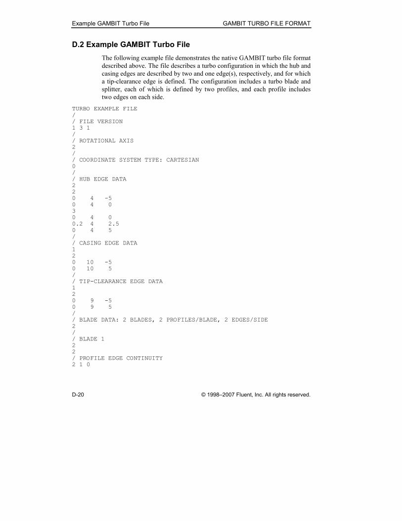
D.2 Example GAMBIT Turbo File
The following example file demonstrates the native GAMBIT turbo file format
described above. The file describes a turbo configuration in which the hub and
casing edges are described by two and one edge(s), respectively, and for which
a tip-clearance edge is defined. The configuration includes a turbo blade and
splitter, each of which is defined by two profiles, and each profile includes
two edges on each side.
TURBO EXAMPLE FILE
/
/ FILE VERSION
1 3 1
/
/ ROTATIONAL AXIS
2
/
/ COORDINATE SYSTEM TYPE: CARTESIAN
0
/
/ HUB EDGE DATA
2
2
0 4 -5
0 4 0
3
0 4 0
0.2 4 2.5
0 4 5
/
/ CASING EDGE DATA
1
2
0 10 -5
0 10 5
/
/ TIP-CLEARANCE EDGE DATA
1
2
0 9 -5
0 9 5
/
/ BLADE DATA: 2 BLADES, 2 PROFILES/BLADE, 2 EDGES/SIDE
2
/
/ BLADE 1
2
2
/ PROFILE EDGE CONTINUITY
2 1 0
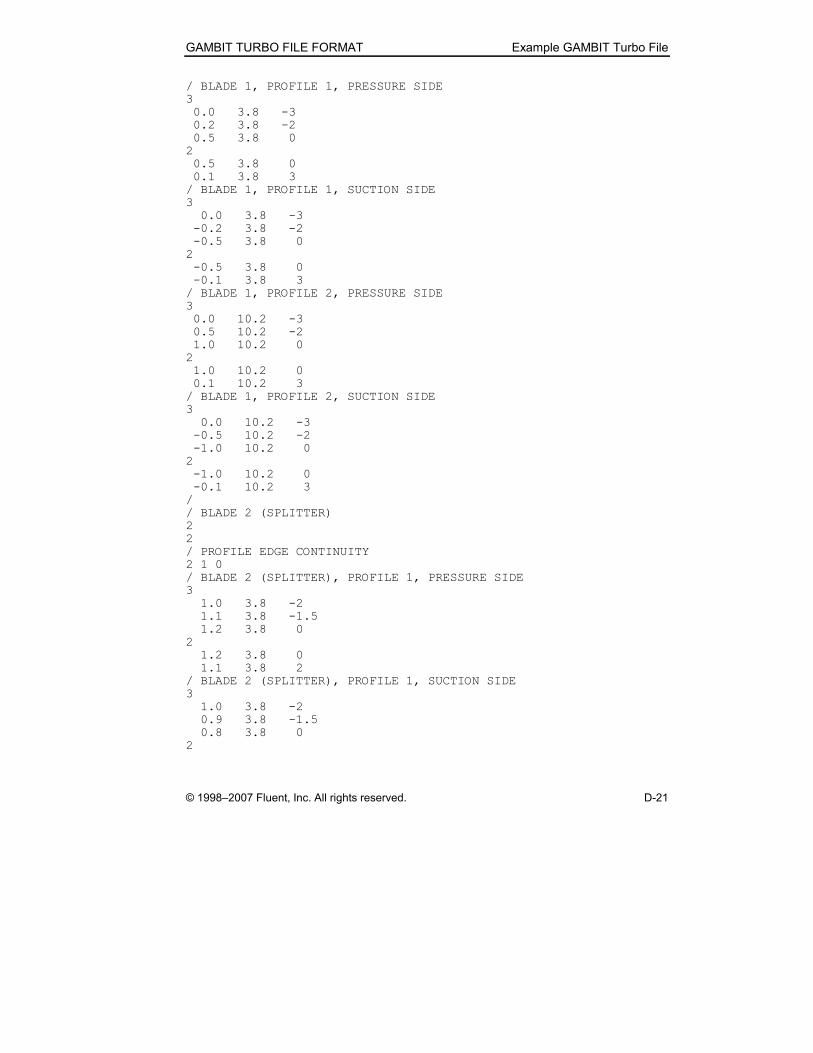
GAMBIT TURBO FILE FORMAT Example GAMBIT Turbo File
© 1998–2007 Fluent, Inc. All rights reserved. D-21
/ BLADE 1, PROFILE 1, PRESSURE SIDE
3
0.0 3.8 -3
0.2 3.8 -2
0.5 3.8 0
2
0.5 3.8 0
0.1 3.8 3
/ BLADE 1, PROFILE 1, SUCTION SIDE
3
0.0 3.8 -3
-0.2 3.8 -2
-0.5 3.8 0
2
-0.5 3.8 0
-0.1 3.8 3
/ BLADE 1, PROFILE 2, PRESSURE SIDE
3
0.0 10.2 -3
0.5 10.2 -2
1.0 10.2 0
2
1.0 10.2 0
0.1 10.2 3
/ BLADE 1, PROFILE 2, SUCTION SIDE
3
0.0 10.2 -3
-0.5 10.2 -2
-1.0 10.2 0
2
-1.0 10.2 0
-0.1 10.2 3
/
/ BLADE 2 (SPLITTER)
2
2
/ PROFILE EDGE CONTINUITY
2 1 0
/ BLADE 2 (SPLITTER), PROFILE 1, PRESSURE SIDE
3
1.0 3.8 -2
1.1 3.8 -1.5
1.2 3.8 0
2
1.2 3.8 0
1.1 3.8 2
/ BLADE 2 (SPLITTER), PROFILE 1, SUCTION SIDE
3
1.0 3.8 -2
0.9 3.8 -1.5
0.8 3.8 0
2
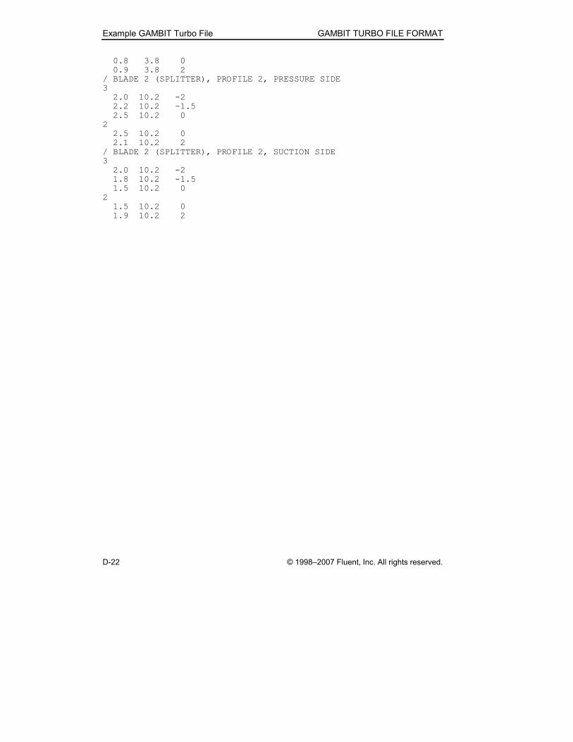
Example GAMBIT Turbo File GAMBIT TURBO FILE FORMAT
D-22 © 1998–2007 Fluent, Inc. All rights reserved.
0.8 3.8 0
0.9 3.8 2
/ BLADE 2 (SPLITTER), PROFILE 2, PRESSURE SIDE
3
2.0 10.2 -2
2.2 10.2 -1.5
2.5 10.2 0
2
2.5 10.2 0
2.1 10.2 2
/ BLADE 2 (SPLITTER), PROFILE 2, SUCTION SIDE
3
2.0 10.2 -2
1.8 10.2 -1.5
1.5 10.2 0
2
1.5 10.2 0
1.9 10.2 2