D-FV-10A3200 3(US) Armored Purgemeter - Buck SalesUS) Variable Area Flowmeters Armored Purgemeter...
14
Data Sheet D-FV-10A3200_3(US) Variable Area Flowmeters Armored Purgemeter 10A3200 Armored Purgemeter Series 10A3200 Function - The armored variable area flowmeter offers new possibilities for metering small flowrates of liquids and gases. The instrument is particularly well suited for metering cloudy, opaque or aggressive fluids. Applications - The instrument can be installed in Chemical, Petrochemical Industries, gas analyzers, process systems, well systems and wherever glass meter tubes cannot be used for safety reasons. Essential Features - Measures ranges from 0.26 to 800 GPH water or 1.7 to 3300 SCFH air. - Easy to read percent or direct reading scale. - Integral needle valve in the inlet or outlet (10A3220). - Single and/or dual alarms - Analog output signal 4-20 mA (10A3250/55) - Differential pressure regulator (10A3220) - Installation length only 90 mm (10A3220) - Optional stainless steel indicator housing.
Transcript of D-FV-10A3200 3(US) Armored Purgemeter - Buck SalesUS) Variable Area Flowmeters Armored Purgemeter...

Data SheetD-FV-10A3200_3(US)
Variable Area FlowmetersArmored Purgemeter
10A3200
Armored PurgemeterSeries 10A3200
Function- The armored variable area flowmeter
offers new possibilities for metering smallflowrates of liquids and gases. Theinstrument is particularly well suited formetering cloudy, opaque or aggressivefluids.
Applications- The instrument can be installed in
Chemical, Petrochemical Industries, gasanalyzers, process systems, well systemsand wherever glass meter tubes cannot beused for safety reasons.
Essential Features- Measures ranges from 0.26 to 800 GPH
water or 1.7 to 3300 SCFH air.- Easy to read percent or direct reading
scale.- Integral needle valve in the inlet or outlet
(10A3220).- Single and/or dual alarms- Analog output signal 4-20 mA
(10A3250/55)- Differential pressure regulator (10A3220)- Installation length only 90 mm (10A3220)- Optional stainless steel indicator housing.
2
D-FV-10A3200_3Variable Area FlowmetersArmored Purgemeter - 10A3200
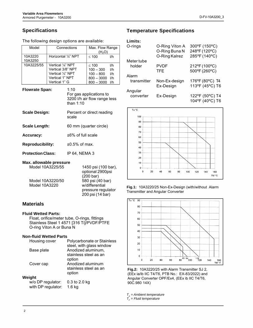
Temperature Specifications
Limits:O-rings O-Ring Viton A 300ºF (150ºC)
O-Ring Buna N 248ºF (120ºC)O-Ring Kalrez 285ºF (140ºC)
Meter tubeholder PVDF 212ºF (100ºC)
TFE 500ºF (260ºC)Alarm
transmitter Non-Ex-design 176ºF (80ºC) T4Ex-Design 113ºF (45ºC) T6
Angularconverter Ex-Design 122ºF (50ºC) T4
104ºF (40ºC) T6
Specifications
The following design options are available:
Flowrate Span: 1:10For gas applications to3200 l/h air flow range lessthan 1:10
Scale Design: Percent or direct readingscale
Scale Length: 60 mm (quarter circle)
Accuracy: ±6% of full scale
Reproducibility: ±0.5% of max.
Protection Class: IP 64, NEMA 3
Max. allowable pressureModel 10A3225/55 1450 psi (100 bar),
optional 2900psi(200 bar)
Model 10A3220/50 580 psi (40 bar)Model 10A3220 w/differential
pressure regulator200 psi (14 bar)
Materials
Fluid Wetted Parts:Float, orifice/meter tube, O-rings, fittingsStainless Steel 1 4571 [316 Ti]/PVDF/PTFEO-ring Viton A or Buna N
Non-fluid Wetted PartsHousing cover Polycarbonate or Stainless
steel, with glass windowBase plate Anodized aluminum,
stainless steel as anoption
Cover cap Anodized aluminumstainless steel as anoption
Weightw/o DP regulator: 0.3 to 2.0 kgwith DP regulator: 1.6 kg
Model Connections Max. Flow Range (H2O)
10A3220 10A3250
Horizontal ¼” NPT ≤ 100 l/h
10A3225/55 Vertical ¼” NPT Vertical 3/8” NPT Vertical ½” NPT Vertical 1” NPT Vertical 1” G
≤ 100 l/h 100 – 300 l/h 100 – 800 l/h 800 – 3000 l/h 800 – 3000 l/h
Fig.1: 10A3220/25 Non-Ex-Design (with/without AlarmTransmitter and Angular Converter
Fig.2: 10A3220/25 with Alarm Transmitter SJ 2,(EEx ia/ib IIC T4/T6, PTB No.: EX-83/2022) andAngular Converter OPF/Ex4, (EEx ib IIC T4/T6,90C.980 14X)
TA = Ambient temperatureTF = Fluid temperature

3
Variable Area FlowmetersArmored Purgemeter - 10A3200 D-FV-10A3200_3
Specifications, Accessories
Alarm Transmitter, Model D10A3220/25Alarm contacts can be installed in the housing,which respond at min. and/or max. flowrate. Theycan be used to switch the power to pumps, magnetvalves, etc. on or off.The alarm transmitter consists of a slot initiator anda switch amplifier. The switch amplifier is installedoutside of the indicator housing. A control vane (4)initiates the switching procedure when it rotatesinto the slot initiator. The slot initiator can bepositioned using a screw driver.
Fig. 3: Armored Purgemeter 10A3220 Indicator withSingle Alarm
Alarm TransmitterSlot Initiator Type SJ2-N (Pepperl & Fuchs)
Ambient Temperature-20ºC to +45ºC
Certificate of CompliancePTB 99 ATEX2219X; EEx ia llc T6
Alarm Point SettingsSingle alarm: min. 0 to 60%, max. 40 to 100%Double alarm: min. range setting approx.5%
Setting Accuracy±2% of max.
Switch Amplifier (remote)
Output1 or 2 switch relays with potential free contacts
Powermax. 250 V, max. 2A
A Transmitter Power Supply isrequiredfor the Alarm Signal Output -Examples
Amplifier Supply Power Channel KFA5-SR2-Ex1.W P/N 163A012U01
115 V, AC 1 SPDT
KFA6-SR2-Ex1.W P/N 163A012U05
220 V, AC 1 SPDT
KFA5-SR2-Ex1. W . LB P/N 163A012U03
115 V, AC 1 DPDT
KFA6-SR2-Ex1. W . LB P/N 163A012U04
220 V, AC 1 DPDT
KFA5-SR2-Ex2.W P/N 163A012U02
115 V, AC 2 SPDT
KFA6-SR2-Ex2.W P/N 163A012U06
220 V, AC 2 SPDT
KFD2-SR2-Ex1.W P/N D163A011U03
24 V, DC 1 SPDT
KFD2-SR2-Ex2.W P/N D163A011U06
24 V, DC 2 SPDT
KFD2-SR2-Ex1.W .LB P/N 163A012U07
24 V, DC 1 DPDT
These switch amplifiers are models manufactured byPepperl & Fuchs. Others could be used equally as well.
Electronic ConverterType: OPF Ex 4-2R/L.P. (Mfg’r.
Tempress A/S)
Model 10A3250/55-ExThe model 10A3250/55 flowmeters incorporate anangular converter. The converter is mounted onthe pointer axis and converts the pointer positioninto a proportional 4-20 mA current value.
Output Signal 4-20 mA-/2-WireUmax = 30 VImax = 30 mACi ≤ 50 nF; Li ≤ 360 μH
Ambient Temperature-20ºC to +40ºC
Certificate of Compliance No.DEMCO- No. 90C.98014X, EEX ib IIC T6
1 Slot Initiator2 Indicator3 Alarm setting4 Control vane

4
D-FV-10A3200_3Variable Area FlowmetersArmored Purgemeter - 10A3200
Indicator with Analog Output Signal 4-20mA / 2 wire
Differential Pressure Regulator, Model53RT2110, Model 10A3220
The differential pressure regulator when used inconjunction with the purgemeter maintains theflowrate set using the needle valve at a constantvalue.
Max. allow. Differential Pressure100 psi (7 bar)
Connections1/4” NPT
Materials
HousingStn. stl. 1.4571 [316Ti]
DiaphragmViton A (max. 150ºC)*
O-RingsViton A*
SpringsStn. Stl. 1.4401 [316]
Valve Seat and ShaftStn. stl. 1.4401 [316]
Connecting PipingStn. stl. 1.4401 [316]
Pipe CouplingStn. stl. 1.4401 [316]
*For Ammonia Buna N is required, max. 120ºC

5
Variable Area FlowmetersArmored Purgemeter - 10A3200 D-FV-10A3200_3
CAPACITY TABLE 1Float & Metering Tube
Maximum Flow (1/4” NPT Vertical or Horizontal Connections)
CAPACITY TABLE 2Float & Orifice
Maximum Flow (Vertical Connections Only)
[1] Vstd: Allowable viscosity without calibration.[2] Pdiff: Min. required ΔP in psi if operating with differential pressure regulator. "-" not available.[3] Pstat: Min. required pressure in psig to eliminate float bounce, without using twisted guide rod float.[4] Pmin: Min. required pressure in psig with gas damping (twisted rod). "-" not available.[5] ΔP: Total pressure loss at maximum flow.
Water Air
Sp. Gr. 1.0 1013 Mbar 0ºC
14.7 Psia 70ºF
Vstd [1]
Pdiff [2]
Pstat [3]
Pmin [4]
DP [5]
Inches
Capacity Code Connection
Size
I/h GPH N I/h SCFH cps psi psig psig W.C. . 100 26 3200 115 8 - 58 4.5 24 20 160 42 5000 180 8 - 58 4.5 28 21 200 52 6200 220 8 - 58 4.5 32 22 250 66 7800 290 8 - 58 4.5 36 23
3/8”
300 78 9200 330 8 - 58 4.5 40 24 400 105 12500 460 4 - 58 7.3 30 30 500 135 15000 560 4 - 58 7.3 34 31 600 160 18000 660 4 - 58 7.3 38 32 700 190 21000 780 4 - 58 7.3 46 33
1/2”
800 210 24000 880 4 - 58 7.3 52 34 l/h GPM N l/h SCFM
800 3.5 24000 14.7 3 - 232 5.8 24 40 1000 4.3 30000 18.3 3 - 232 5.8 25 41 1600 7.0 48000 28.3 3 - 232 5.8 30 42 2000 9.0 60000 36.7 3 - 232 5.8 34 43 2500 11.0 74000 45.0 3 - 232 5.8 42 44
1”
3000 13.3 89000 55.0 3 - 232 5.8 52 45
Water Air
Sp. Gr. 1.0 1013 Mbar 0ºC
14.7 Psia 70ºF
Vstd [1]
Pdiff [2]
Pstat [3]
Pmin [4]
DP [5]
Inches
Capacity Code
I/h GPH N I/h SCFH cps psi psig psig W.C. . 1 0.26 35 1.7 4 10.2 14.5 - 3.2 01
1.6 0.42 54 2.4 4 10.2 14.5 - 3.2 02 2.5 0.66 100 3.6 6 10.2 14.5 - 3.2 03 4 1.05 160 5.8 6 10.2 14.5 - 3.2 04 6 1.6 230 8.2 18 10.2 14.5 - 3.2 05
10 26 350 12.5 18 10.2 14.5 - 3.2 06 16 4.2 540 19 18 10.2 14.5 - 3.2 07 25 6.6 850 30 18 10.2 14.5 - 3.6 08 40 10.5 1250 46 18 10.2 14.5 - 4.2 09 60 16 1900 70 18 10.2 14.5 - 5.0 10
100 26 3100 115 12 - 14.5 - 6.8 11

6
D-FV-10A3200_3Variable Area FlowmetersArmored Purgemeter - 10A3200
Dimensions 10A3220/25
Fig. 4: Model 10A3220, 25 to 800 l/h Water
a Øb c d e f g Model Flow range ≤100 l/h Water
SW19 18 125 29 ¼” NPT 34 29 10A3220/25
Flow range 100 l/h to 300 l/h Water
SW24 25 164 48.5 3/8” NPT
30.5 32.5 10A3225
Flow range ≤400 l/h to 800 l/h Water
SW27 25 164 48.5 ½” NPT 30.5 32.5 10A3225
Flow range 800 l/h to 3000 Water
SW50 50 230 81 1” G 1” NPT
18 45 10A3225
Fig. 5: Model 10A3225, 800 to 3000 l/h Water
SW = Size of Wrench
1 Plastic cover2 Stn. stl. cover
ISO Projection Method E
All dim´s in mm
ISO Projection Method E
All dim´s in mm
Model 10A3220 ≤≤≤≤≤100 l/h Water(horizontal pipe connections)
Model 10A3225 ≤ ≤ ≤ ≤ ≤800 l/h Water(vertical pipe connections) Connection cable 1750 mm lg
230
81
14
79
68
18
1" NPT
45 / 50
ø 50
SW = 50
1" NPTSW = 50
1) 2)
���
Connection cable 1750 mm long

7
Variable Area FlowmetersArmored Purgemeter - 10A3200 D-FV-10A3200_3
Dimensions 10A3250/55
a Øb c d e g h Model Flow range ≤ 100 l/h W ater
SW 19 18 125 29 ¼” NPT 31 58 10A3250/55
Flow range 100 l/h to 300 l/h W ater
SW 24 25 164 48.5 3/8” NPT
34.5 61.5 10A3255
Flow range ≤ 400 l/h to 800 l/h W ater
SW 27 25 164 48.5 ½” NPT 34.5 61.5 10A3255
Flow range 800 l/h to 3000 W ater
SW 50 50 230 81 1” G 1” NPT
- 74 10A3255
Fig. 6: Model 10A3250, 25 to 800 l/h Water
Fig.7: Model 10A3255, 800 to 3000 l/h Water
SW = Size of Wrench
230
1" NPT 79
68
81
74
14
ø 50
SW = 50
SW = 50
1" NPT
ABB
ISO Projection Method E
All dim´s in mm
ISO Projection Method E
All dim´s in mm
Connection cable ca. 1750mmCable connector Pg7
Connection Cable - 1750 long:Cable connector Pg7
Connection Cable - 1750 long:Cable connector Pg7
Model 10A3250 ≤ ≤ ≤ ≤ ≤ l/h Armored Purgemeterwith Electronic Converter
Model 10A3250/55 ≤≤≤≤≤800 l/h ArmoredPurgemeter with Electronic Converter
a gh

8
D-FV-10A3200_3Variable Area FlowmetersArmored Purgemeter - 10A3200
Fig. 8:
ISO Projection Method E
All dim´s in mm
Model 10A3220/10A3250(with differential pressureregulator for wall mounting)
Model 10A3220/10A3250(with differential pressureregulator for pipeline mount.

9
Variable Area FlowmetersArmored Purgemeter - 10A3200 D-FV-10A3200_3
Notes:1. For intrinsically safe installations, all wiring to be in
accordance with ANSI/ISA RP12.6.2a. • for intrinsically safe transmitter installations using one (1) sensor.
• for non-hazardous or Div 2 transmitter installations using (2) sensors.Field wiring between flowmeter and control amplifier(s) should be twisted pair, 25awg or larger. Maximum cable length per Table 1. All field wiring by others.
b. • for intrinsically safe transmitter installations using two (2) sensors.Field wiring between flowmeter and control amplifiers must be two (2)independent twisted pairs. 25 awg or larger. Maximum cable length perTable 1. All field wiring by others.
3. Pepperl & Fuchs slot sensor SJ 3.5N.4. Pepperl & Fuchs control amplifier (relay) KFA5-SR2-Ex1.W (SPDT);
KFA5-SR2-Ex1.W. LB (DPDT)5. Pepperl & Fuchs control amplifier (relay) KFA5-SR2-Ex2.W (SPDT)6. Contacts are unpowered and are rated at 2 A, 250V; relay contacts are shown
de-energized. Relay contacts are not to be paralleled to increase contact rating.
Transmitter Location
Maximum Length (Note 1)
Non-Hazardous or Div 2 1 mi. 1.5 km Class I, Div 1, Groups A & B 3000 ft. 900 m Class I, Div 1, Groups C & D Class II, Div 1, Groups E, F & G
1 mi. 1.5 km
Table 1 Cable Length
Cable Capacitance ≤60 pF/ft (197pF/m)Inductance ≤0.2 μH/ft (0.656 μH/m)
10
D-FV-10A3200_3Variable Area FlowmetersArmored Purgemeter - 10A3200
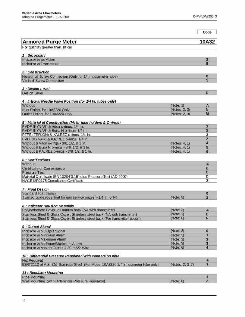
Code
Armored Purge Meter 10A32For quantity greater than 10 call
1 : SecondaryIndicator w/wo Alarm 2Indicator w/Transmitter 5
2 : ConstructionHorizontal Screw Connection (Only for 1/4 In. diameter tube) 0Vertical Screw Connection 5
3 : Design LevelDesign Level D
4 : Integral Needle Valve Position (for 1/4 In. tubes only)Without (Note: 1) AInlet Fitting, for 10A3220 Only (Notes: 2, 3) NOutlet Fitting, for 10A3220 Only (Notes: 2, 3) M
5 : Material of Construction (Meter tube holders & O-rings)PVDF (KYNAR) & Viton o-rings, 1/4 In. 1PVDF (KYNAR) & Buna N o-rings, 1/4 In. 2PTFE (TEFLON) & KALREZ o-rings, 1/4 In. 3PVDF(KYNAR) & KALREZ o-rings, 1/4 In. ZWithout & Viton o-rings - 3/8, 1/2, & 1 In. (Notes: 4, 1) 4Without & Buna N o-rings - 3/8, 1/2, & 1 In. (Notes: 4, 1) 5Without & KALREZ o-rings - 3/8, 1/2, & 1 In. (Notes: 4, 1) 6
6 : CertificationsWithout ACertificate of Conformance BPressure Test CMaterial Certificate (EN 10204-3.1B) plus Pressure Test (AD-2000) DNACE MR0175 Compliance Certificate Z
7 : Float DesignStandard float design 0Twisted guide rode float for gas service (sizes > 1/4 In. only) (Note: 5) 1
8 : Indicator Housing MaterialsPolycarbonate Cover, aluminum back (NA with transmitter) (Note: 3) AStainless Steel & Glass Cover, Stainless steel back (NA with transmitter) (Note: 3) EStainless Steel & Glass Cover, Stainless steel back (For transmitter option) (Note: 6) F
9 : Output SignalIndicator w/o Output Signal (Note: 3) 0Indicator w/Minimum Alarm (Note: 3) 1Indicator w/Maximum Alarm (Note: 3) 2Indicator w/Minimum/Maximum Alarm (Note: 3) 3Indicator w/Analog-Output 4-20 mA/2-Wire (Note: 6) 4
10 : Differential Pressure Regulator (with connection pipe)Not Required A53RT2110 of AISI 316 Stainless Steel (For Model 10A3220 1/4 In. diameter tube only) (Notes: 2, 3, 7) T
11 : Regulator MountingPipe Mounting 1Wall Mounting (with Differential Pressure Regulator) (Note: 8) 2

11
Variable Area FlowmetersArmored Purgemeter - 10A3200 D-FV-10A3200_3
10A32 Code
12 : Connection Size1/4 In. NPT (100 l/h or less) (Note: 9) A3/8 In. NPT (100 to 300 l/h) (3/8 In. tube) (Note: 10) K1/2 In. NPT (100 to 300 l/h) (3/8 In. tube) (Note: 10) M1/2 In. NPT (400 to 800 l/h) (1/2 In. tube) (Note: 10) N1 In. NPT (800 TO 3000 l/h) (1 In. tube) (Note: 10) P1 In. G (800 to 3000 l/h) (1 In. tube) (Note: 10) Q
13 : Instrument Name TagInstrument Name Tag 1
14 : External Alarm RelayNone 0SPDT Single Alarm - 115 Vac (Notes: 3, 11) 1SPDT Dual Alarm - 115 Vac (Notes: 3, 12) 2DPDT Single (or Dual - requires 2 relays) Alarm - 115 Vac (Notes: 3, 13) 3SPDT Single Alarm - 220 Vac (Notes: 3, 11) 4SPDT Dual Alarm - 220 Vac (Notes: 3, 12) 5DPDT Single (or Dual requires 2 relays) Alarm - 220 Vac (Notes: 3, 13) 6SPDT Single Alarm - 24 Vdc (Notes: 3, 11) 7SPDT Dual Alarm - 24 Vdc (Notes: 3, 12) 8DPDT Single (or Dual - requires 2 relays) Alarm - 24 Vdc (Notes: 3, 13) 9
15 : Flow Range1/4 In. Diameter Tube 1 I/h (Note: 14) 011/4 In. Diameter Tube 1.6 I/h (Note: 14) 021/4 In. Diameter Tube 2.5 I/h (Note: 14) 031/4 In. Diameter Tube 4 I/h (Note: 14) 041/4 In. Diameter Tube 6 I/h (Note: 14) 051/4 In. Diameter Tube 10 I/h (Note: 14) 061/4 In. Diameter Tube 16 I/h (Note: 14) 071/4 In. Diameter Tube 25 I/h (Note: 14) 081/4 In. Diameter Tube 40 I/h (Note: 14) 091/4 In. Diameter Tube 60 I/h (Note: 14) 101/4 In. Diameter Tube 100 I/h (Note: 14) 113/8 In. Diameter Tube 100 l/h (Notes: 15, 1) 203/8 In. Diameter Tube 160 l/h (Notes: 15, 1) 213/8 In. Diameter Tube 200 l/h (Notes: 15, 1) 223/8 In. Diameter Tube 250 l/h (Notes: 15, 1) 233/8 In. Diameter Tube 300 l/h (Notes: 15, 1) 241/2 In. Diameter Tube 400 l/h (Notes: 16, 1) 301/2 In. Diameter Tube 500 l/h (Notes: 16, 1) 311/2 In. Diameter Tube 600 l/h (Notes: 16, 1) 321/2 In. Diameter Tube 700 l/h (Notes: 16, 1) 331/2 In. Diameter Tube 800 l/h (Notes: 16, 1) 341 In. Diameter Tube 800 l/h (Notes: 17, 1) 401 In. Diameter Tube 1000 l/h (Notes: 17, 1) 411 In. Diameter Tube 1600 l/h (Notes: 17, 1) 421 In. Diameter Tube 2000 l/h (Notes: 17, 1) 431 In. Diameter Tube 2500 l/h (Notes: 17, 1) 441 In. Diameter Tube 3000 l/h (Notes: 17, 1) 45
16 : Scale TypeLinear , Liq/Gas Visc <1.4 CPS (Note: 23) 1Non Linear Liq Visc >1.4 CPS (Note: 23) 4Non Linear Liq Visc >1.4 CPS (Note: 23) 5Linear Gas (Note: 23) 2Linear Gas (Note: 23) 3
12
D-FV-10A3200_3Variable Area FlowmetersArmored Purgemeter - 10A3200
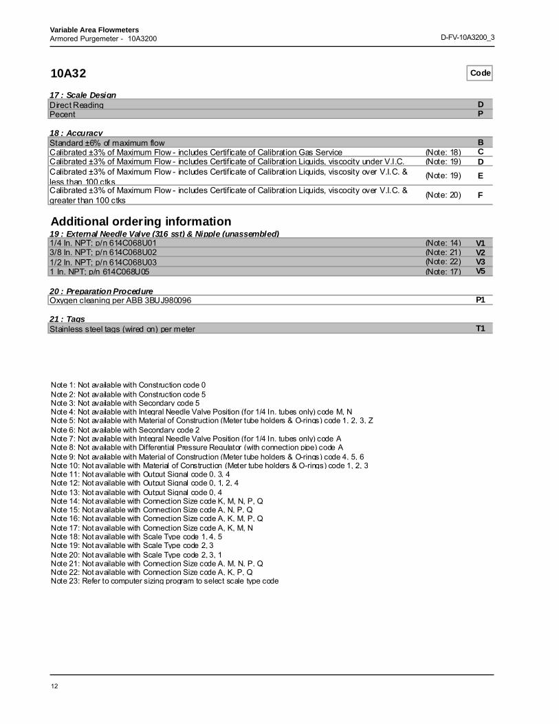
10A32 Code
17 : Scale DesignDirect Reading DPecent P
18 : AccuracyStandard ±6% of maximum flow BCalibrated ±3% of Maximum Flow - includes Certificate of Calibration Gas Service (Note: 18) CCalibrated ±3% of Maximum Flow - includes Certificate of Calibration Liquids, viscocity under V.I.C. (Note: 19) DCalibrated ±3% of Maximum Flow - includes Certificate of Calibration Liquids, viscosity over V.I.C. & less than 100 ctks
(Note: 19) E
Calibrated ±3% of Maximum Flow - includes Certificate of Calibration Liquids, viscocity over V.I.C. & greater than 100 ctks (Note: 20) F
Additional ordering information19 : External Needle Valve (316 sst) & Nipple (unassembled)1/4 In. NPT; p/n 614C068U01 (Note: 14) V13/8 In. NPT; p/n 614C068U02 (Note: 21) V21/2 In. NPT; p/n 614C068U03 (Note: 22) V31 In. NPT; p/n 614C068U05 (Note: 17) V5
20 : Preparation ProcedureOxygen cleaning per ABB 3BUJ980096 P1
21 : TagsStainless steel tags (wired on) per meter T1
Note 1: Not available with Construction code 0Note 2: Not available with Construction code 5Note 3: Not available with Secondary code 5Note 4: Not available with Integral Needle Valve Position (for 1/4 In. tubes only) code M, NNote 5: Not available with Material of Construction (Meter tube holders & O-rings) code 1, 2, 3, ZNote 6: Not available with Secondary code 2Note 7: Not available with Integral Needle Valve Position (for 1/4 In. tubes only) code ANote 8: Not available with Differential Pressure Regulator (with connection pipe) code ANote 9: Not available with Material of Construction (Meter tube holders & O-rings) code 4, 5, 6Note 10: Not available with Material of Construction (Meter tube holders & O-rings) code 1, 2, 3Note 11: Not available with Output Signal code 0, 3, 4Note 12: Not available with Output Signal code 0, 1, 2, 4Note 13: Not available with Output Signal code 0, 4Note 14: Not available with Connection Size code K, M, N, P, QNote 15: Not available with Connection Size code A, N, P, QNote 16: Not available with Connection Size code A, K, M, P, QNote 17: Not available with Connection Size code A, K, M, NNote 18: Not available with Scale Type code 1, 4, 5Note 19: Not available with Scale Type code 2, 3Note 20: Not available with Scale Type code 2, 3, 1Note 21: Not available with Connection Size code A, M, N, P, QNote 22: Not available with Connection Size code A, K, P, QNote 23: Refer to computer sizing program to select scale type code

13
Variable Area FlowmetersArmored Purgemeter - 10A3200 D-FV-10A3200_3
NOTES:

14
D-FV-10A3200_3Variable Area FlowmetersArmored Purgemeter - 10A3200
The Company’s policy is one of continuous productimprovement and the right is reserved to modify the
information contained herein without notice.
Printed in USA (4.2.09)
© ABB 2003, 2009
ABB Inc.125 East County Line RoadWarminsterPA 18974USATel: +1 215 674 6000Fax: +1 215 674 7183
D-F
V-10
A32
00_3
(US
)
ABB (www.abb.com) is a leader in power and automation technologies that enableutility and industry customers to improve their performance while loweringenvironmental impact. The ABB Group of companies operates in around 100countries and employs about 120,000 people.
www.abb.com/instrumentation
NOTES: