D-600 SERIES SOLID STATE IGNITION - Toro · D-600 SERIES SOLID STATE IGNITION HOW SOLID STATE...
8
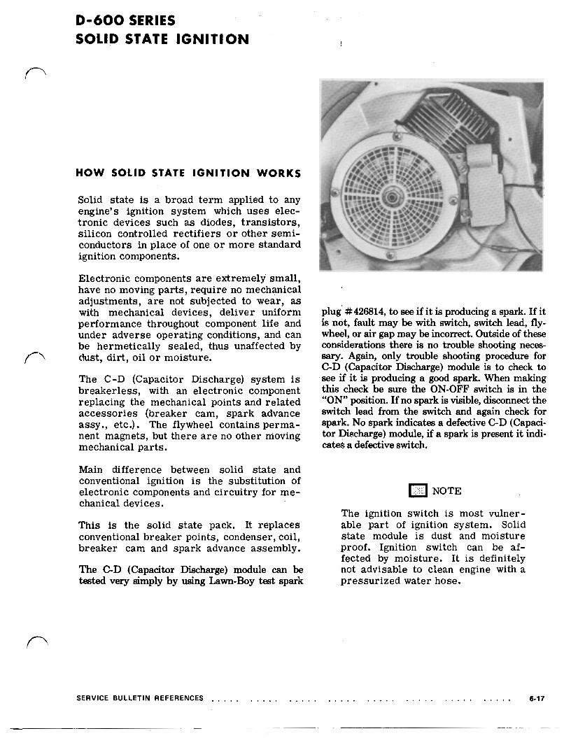
D-600 SERIES SOLID STATE IGNITION HOW SOLID STATE I G N I T I O N WORKS Solid state is a broad term applied to any engine’s ignition system which uses elec- tronic devices such as diodes, transistors, silicon controlled rectifiers or other semi- conductors in place of one or more standard ignition components. Electronic components are extremely small, have no moving parts, require no mechanical adjustments, are not subjectedto wear, as with mechanical devices, deliver uniform performancethroughoutcomponentlife and under adverse operating conditions, and can be hermetically sealed, thus unaffected by dust, dirt, oil or moisture. The C-D (Capacitor Discharge) system is breakerless, with an electronic component replacing the mechanical points and related accessories (breaker cam, spark advance assy., etc.). The flywheel contains perma- nent magnets, but there are no other moving mechanical parts. Main difference between solid state and conventional ignition is the substitution of electronic components and circuitry for me- chanical devices. This is the solid state pack. It replaces conventional breaker points, condenser, coil, breakercam and spark advance assembly. The C-D (Capacitor Discharge) module can be tested very simply by using Lawn-Boy test spark plug #426814, to see if it is producing a spark. If it is not, fault may be with switch, switch lead, fly- wheel, or air gap may be incorrect. Outside of these considerations there is no trouble shooting neces- sary. Again, only trouble shooting procedure for C-D (Capacitor Discharge) module is to check to see if it is producing a good spark. When making this check be sure the ON-OFF switch is in the “ON” position. If no spark is visible, disconnect the switch lead from the switch and again check for spark. No spark indicates a defective C-D(Capaci- tor Discharge) module, if a spark is present it indi- ca& a defective switch. NOTE Theignition switch is most vulner- able part of ignition system. Solid state module is dust and moisture proof. Ignition switch can be af- fected by moisture. It is definitely not advisable to clean engine with a pressurized water hose. SERVICE BULLETIN REFERENCES 6-17
-
Upload
nguyenkiet -
Category
Documents
-
view
238 -
download
0
Transcript of D-600 SERIES SOLID STATE IGNITION - Toro · D-600 SERIES SOLID STATE IGNITION HOW SOLID STATE...
D-600 SERIES SOLID STATE I G N I T I O N
HOW SOLID STATE I G N I T I O N WORKS
Solid state is a broad term applied to any engine’s ignition system which uses elec- tronic devices such as diodes, transistors, silicon controlled rectifiers or other semi- conductors in place of one or more standard ignition components.
Electronic components are extremely small, have no moving parts, require no mechanical adjustments, are not subjected to wear, as with mechanical devices, deliver uniform performance throughout component life and under adverse operating conditions, and can be hermetically sealed, thus unaffected by dust, dirt, oil or moisture.
The C-D (Capacitor Discharge) system is breakerless, with an electronic component replacing the mechanical points and related accessories (breaker cam, spark advance assy., etc.). The flywheel contains perma- nent magnets, but there a r e no other moving mechanical parts.
Main difference between solid state and conventional ignition is the substitution of electronic components and circuitry for me- chanical devices.
This is the solid state pack. It replaces conventional breaker points, condenser, coil, breaker cam and spark advance assembly.
The C-D (Capacitor Discharge) module can be tested very simply by using Lawn-Boy test spark
plug #426814, to see if it is producing a spark. If it is not, fault may be with switch, switch lead, fly- wheel, or air gap may be incorrect. Outside of these considerations there is no trouble shooting neces- sary. Again, only trouble shooting procedure for C-D (Capacitor Discharge) module is to check to see if it is producing a good spark. When making this check be sure the ON-OFF switch is in the “ON” position. If no spark is visible, disconnect the switch lead from the switch and again check for spark. No spark indicates a defective C-D (Capaci- tor Discharge) module, if a spark is present it indi- ca& a defective switch.
NOTE
The ignition switch is most vulner- able part of ignition system. Solid state module is dust and moisture proof. Ignition switch can be af- fected by moisture. It is definitely not advisable to clean engine with a pressurized water hose.
SERVICE BULLETIN REFERENCES 6-17
D-600 SERIES (cont’d)
SWITCH L E A D
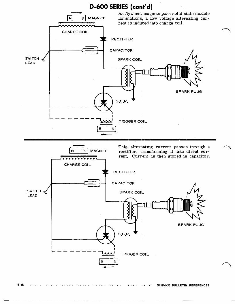
MAGNET As flywheel magnets pass solid state module laminations, a low voltage alternating cur- rent is induced into charge coil.
CHARGE COIL
RECTIFIER
CAPACITOR
SPARK COIL
SPARK PLUG
I I I
TRIGGER COIL
SWITCH L E A D
MAGNET This alternating current passes through a rectifier, transforming it into direct cur- rent. Current is then stored in capacitor.
HARGE COIL
RECTIFIER
CAPACITOR
SPARK COIL
SPARK PLUG
I TRIGGER COIL

0-600 SERIES (cont'd)
Flywheel magnets rotate approximately 350" until they pass laminations, inducing a small electrical charge into trigger coil. At starting speeds, this charge has proper magnitude to turn on silicon controlled rec- tifier (solid state switch) at retarded posi- tion for easy starting. This is illustrated as 5" or retard firing position,
SERVICE BULLETIN REFERENCES 6-19

0-600 SERIES (cont'd)
When engine reaches approximately 800 evolutions per minute,. advance firing
commences. Flywheel magnets travel ap- proximately 330°, at which time enough voltage is induced into trigger coil to fire silicon controlled rectifier (solid state switch). See advanced firing position 25'.
FLYWHEEL
SWITCH LEAD
When silicon controlled rectifier is trig- gered, up to 300 volts stored in capacitor travel to spark coil where it is stepped up instantaneously to a maximum of 30,000 volts and discharged across electrodes of
[=] MAGNET
CHARGE COIL spark plug.
RECTIFIER
CAPACITOR
SPARK COIL
SPARK PLUG
TRIGGER COIL
6-20 SERVICE BULLETIN REFERENCES

3. Insert non-metallic gauge between C-D pack laminations and magnets (magnets will pull the C-D pack in tightly). Two screws securing module a r e then tight- ened. The .OlO gap is set between two inside legs of laminations and magnets. Outer ends of laminations will be further from the flywheel since curvature of laminations does not conform to that of flywheel.
1. Flywheel and solid state module pack can be exposed very easily by removing shroud, fuel hoses and air baffle from armature plate. Remove kill switch lead from ignition switch.
2. Clearance is obtained by rotating the flywheel until flywheel magnets are ad- jacent to the solid state pack as illus- trated. CORRECT AIR GAP IS .010.
NOTE
Use Lawn-Boy Air Gap Gauge Part No. 604659.
C.D. IGNITION PACK
& ONLY THESE 2 SURFACES (HEELS) BETWEEN FLYWHEEL MAGNET
OF C.D. LAMINATION ASSEMBLY.
FLYWHEEL
COUNTERWEIGHT
FLY WHEEL REPLACEMENT
1. Remove spark plug and install Piston Stop Part No. 677389.. Remove shroud, fuel hoses and air baffle from armature piate.
SAFETY WARNING
If engine has been running allow 10 seconds, before removing spark plug lead wire. This will allow charge in C-D pack to lead off.

Using a box end wrench remove flywheel nut. If necessary, use a soft headed (leather or plastic) hammer to loosen nut.
3. Place fingers under flywheel screen and apply upward pressure. At the same time, strike opposite side of flywheel at screen retaining screw with a soft headed hammer to break flywheel loose as shown.
MAKE SURE KEY IS INSTALLED CORRECTLY
RIGHT WRONG
0-600 FLYWHEEL IS USED ON SOME BUT NOT ALL D-400 SERIES ENGINES. CHECK PARTS LISTS CAREFULLY.
4. Remove flywheel. After removing flywheel, note position of flywheel key. Key must be in- stalled with the straight edge in a vertical (straight up and down) position. It should not be installed with straight edge parallel to the crankshaft taper. Remove key with a pair of side cutters or dikes.
5. Check flywheel for wear and strength of flywheel magnets. Check keyway for dis- tortion and/or cracks.
6. Flywheel nut should always be torqued properly when flywheel is re-installed. Correct torque is 30 foot pounds. Fly- wheel hub and crankshaft taper must be absolutely clean void of grease and oil.
6-22 SERVICE BULLETIN REFERENCES
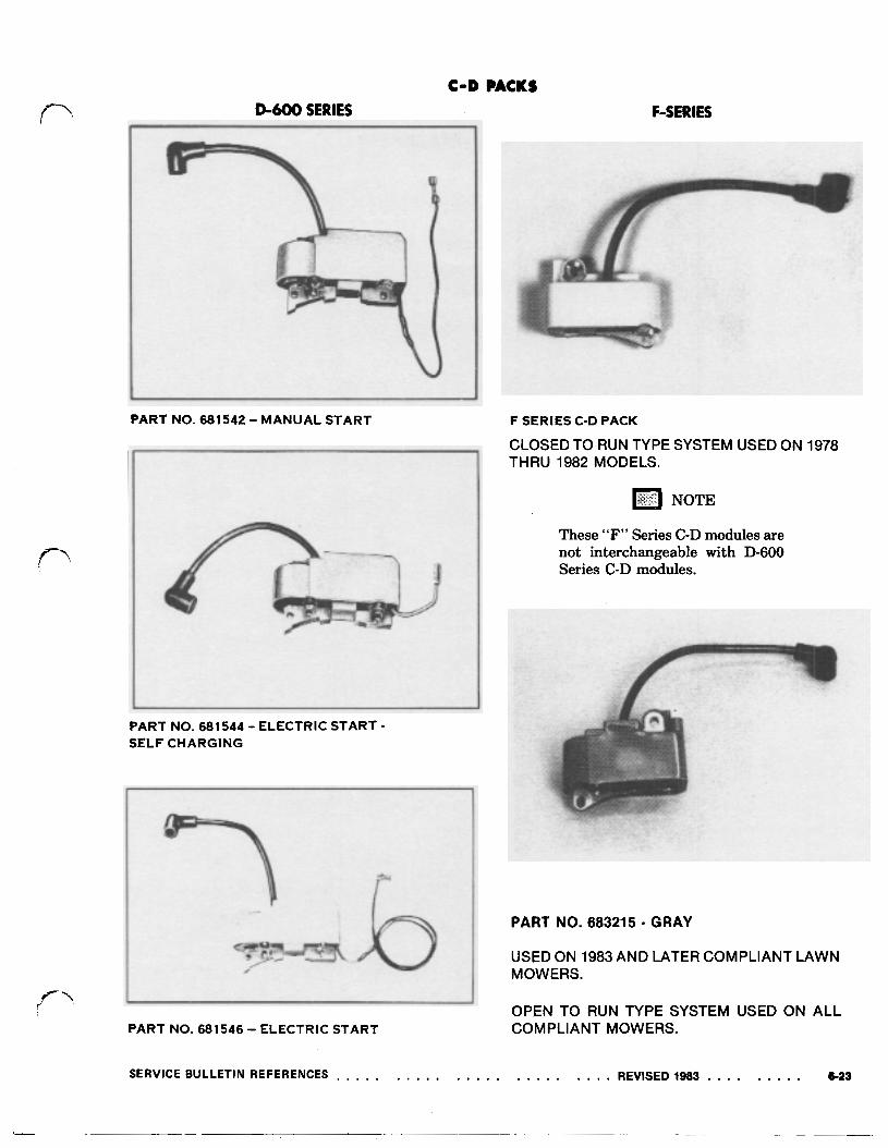
C-D PACKS D-600 SERIES
PART NO. 681542 MANUAL START
F-SERIES
F SERIES C-D PACK
CLOSED TO RUN TYPE SYSTEM USED ON 1978 THRU 1982 MODELS.
These “F” Series C-D modules are not interchangeable with D-600 Series C-D modules.
PART NO. 681 544 ELECTRIC START SELF CHARGING
PART NO. 683215 GRAY
USED ON 1983 AND LATER COMPLIANT LAWN MOWERS.
I PART NO. 681546 ELECTRIC START
OPEN TO RUN TYPE SYSTEM USED ON ALL COMPLIANT MOWERS.
SPARK PLUG 01400 AND D-600 SERIES There are many different types of spark plugs in- tended for various applications and therefore, it is extremely important that the correct plug be used in an engine and torqued correctly. Correct torque is 12 to 15 f t lbs.
LAWN-BOY recommends the use of the Champion CJ-14 spark plug because of its ability to supply, continuously, a hot spark for uninterrupted combustion. Plugs should be cleaned and gapped every 25 hours of operation.
NOTE Prior to installing a new plug always check plug gap. Plug gap is no longer pre-set at factory.
The correct gap for LAWN-BOY engines is:.
D-400 SERIES .025" D-600 SERIES .035"
DO NOT CLEAN PLUG IN SAND BLASTER.
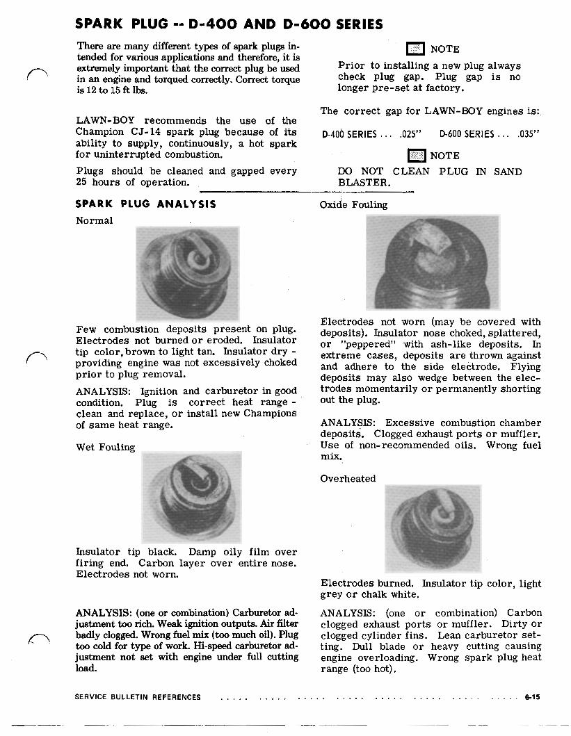
SPARK PLUG ANALYSIS Normal
Few combustion deposits present on plug. Electrodes not burned o r eroded. Insulator tip color, brown to light tan. Insulator dry providing engine was not excessively choked prior to plug removal. ANALYSIS: Ignition and carburetor in good condition. Plug is correct heat range clean and replace, or install new Champions of same heat range.
Oxide Fouling
Electrodes not worn (may be covered with deposits). Insulator nose choked, splattered, o r "peppered" with ash-like deposits. In extreme cases, deposits are thrown against and adhere to the side electrode. Flying deposits may also wedge between the elec- trodes momentarily or permanently shorting out the plug.
ANALYSIS: Excessive combustion chamber deposits. Clogged exhaust ports or muffler.
SERVICE BULLETIN REFERENCES 6-15