D-1000B Heater - Reeves EMS Heater Manual.pdfD-1000B HEATER . Outdoor Use Only . OPERATIONS &...
53
D-1000B HEATER Outdoor Use Only OPERATIONS & MAINTENANCE MANUAL 33 Kings Highway, Orangeburg, NY 10962 Phone: 845-359-6066 ISO 9001: 2000 Registered Quality Management System Fax: 845-365-2114 Hotline: 800-977-3647 DHS Manual Part Number: 1002811 Web: www.drash.com Original Issue: 31 MARCH 2009 Email: [email protected]
Transcript of D-1000B Heater - Reeves EMS Heater Manual.pdfD-1000B HEATER . Outdoor Use Only . OPERATIONS &...
D-1000B HEATER
Outdoor Use Only OPERATIONS & MAINTENANCE MANUAL
33 Kings Highway, Orangeburg, NY 10962 Phone: 845-359-6066
ISO 9001: 2000 Registered Quality Management System
Fax: 845-365-2114 Hotline: 800-977-3647 DHS Manual Part Number: 1002811 Web: www.drash.com Original Issue: 31 MARCH 2009 Email: [email protected]
Revision History
Date Revision Description
03/31/09 1002811 Original Issue.
This manual contains privileged and confidential information proprietary to DHS Systems, LLC and is intended solely for use by its customers. No portion of this document may be reproduced for release to a third party without written consent of DHS Systems, LLC. Additional copies of this manual are available from DHS Systems, LLC.
Copyright © 2009, DHS SYSTEMS LLC
TABLE OF CONTENTS
1. GENERAL................................................................................................................................................... 1-1
1.1 Scope .....................................................................................................................1-1 1.2 Receipt of the D-1000B Heater ..............................................................................1-1 1.3 Equipment Description ...........................................................................................1-1 1.4 Major Components .................................................................................................1-3
1.4.1 Shell........................................................................................................................................... 1-3 1.4.2 Fuel Tank................................................................................................................................... 1-3 1.4.3 Combustion Chamber................................................................................................................ 1-3 1.4.4 Burner Head .............................................................................................................................. 1-3 1.4.5 Electric Motor............................................................................................................................. 1-3 1.4.6 Control System .......................................................................................................................... 1-3 1.4.7 Performance .............................................................................................................................. 1-4 1.4.8 Auxiliary Equipment................................................................................................................... 1-4
1.5 Specifications .........................................................................................................1-4 2. SAFETY...................................................................................................................................................... 2-1
2.1 Scope .....................................................................................................................2-1 2.2 Qualified Personnel ................................................................................................2-1 2.3 Signal Words and Labels .......................................................................................2-1
2.3.1 Danger ....................................................................................................................................... 2-1 2.3.2 Warning ..................................................................................................................................... 2-1 2.3.3 Caution ...................................................................................................................................... 2-1 2.3.4 Important.................................................................................................................................... 2-1
2.4 General Precautions...............................................................................................2-1 2.4.1 Heater ........................................................................................................................................ 2-2 2.4.2 Safety Protections ..................................................................................................................... 2-2
3. STORAGE & TRANSPORT ....................................................................................................................... 3-1 3.1 Scope .....................................................................................................................3-1
3.1.1 Transport and Storage............................................................................................................... 3-1 3.2 Storage...................................................................................................................3-1
3.2.1 Before storing ............................................................................................................................ 3-1 3.2.2 After storing ............................................................................................................................... 3-1
3.3 Shipping .................................................................................................................3-1 4. OPERATIONS ............................................................................................................................................ 4-1
4.1 General ..................................................................................................................4-1 4.2 Control Panel..........................................................................................................4-1 4.3 Start Up Procedure for Normal Operations ............................................................4-1 4.4 Start Up Procedures for Cold Weather Operations ................................................4-2 4.5 Start Up Procedures for High Altitude Operations (4500’/1500m)..........................4-2 4.6 Shut Down Procedure ............................................................................................4-2 4.7 Filling the Fuel Tank ...............................................................................................4-3
5. MAINTENANCE, and REPAIR PROCEDURES........................................................................................ 5-1 5.1 General ..................................................................................................................5-1 5.2 Maintenance...........................................................................................................5-1
5.2.1 Periodic Maintenance ................................................................................................................ 5-1 5.2.2 Daily Maintenance ..................................................................................................................... 5-1 5.2.3 50 Hour Maintenance ................................................................................................................ 5-1 5.2.4 Annual Maintenance.................................................................................................................. 5-2
5.3 Servicing the Fuel Tank..........................................................................................5-2 5.4 Repairs Procedures................................................................................................5-2
5.4.1 General Access ......................................................................................................................... 5-2 5.4.2 Removal and Installation Electric Motor Assembly ................................................................... 5-3
5.4.3 Removal and Installation of the Condenser (Capacitor) ........................................................... 5-5 5.4.4 Removal and Installation of Fuel Filter...................................................................................... 5-6 5.4.5 Removal and Installation of Fuel Pump Assembly.................................................................... 5-7 5.4.6 Removal, Inspection and Installation of Electric Motor / Fuel Pump Coupling ......................... 5-8 5.4.7 Removal and Installation of Fuel Solenoid.............................................................................. 5-10 5.4.8 Removal and Installation of Fuel Nozzle................................................................................. 5-11 5.4.9 Removal and Installation of Ignition & Control Components................................................... 5-12 5.4.10 Removal and Installation of the Transformer and High Temp (H.T.) Leads ........................... 5-13 5.4.11 Removal and Installation of the Photocell ............................................................................... 5-15
6. TEST PROCEDURES ................................................................................................................................ 6-1 6.1 Maintenance Repair Test Procedures ................................................................... 6-1 6.2 Thermostat / CO Detector Control Device Test ..................................................... 6-1 6.3 Smoke Test ........................................................................................................... 6-1 6.4 Fuel Pressure Test ................................................................................................ 6-2
7. TROUBLESHOOTING ............................................................................................................................... 7-1 7.1 General.................................................................................................................. 7-1 7.2 D-1000B Heater..................................................................................................... 7-1
8. ILLUSTRATED PARTS BREAKDOWN .................................................................................................... 8-1 8.1 D-1000B Heater Exploded Detail........................................................................... 8-1 8.2 Burner Head and Nozzle Assembly Exploded View .............................................. 8-2 8.3 Fuel Pump Assembly Exploded View .................................................................... 8-3 8.4 Pre-Heated Fuel Filter Exploded View................................................................... 8-4 8.5 Control Panel Assembly Exploded View................................................................ 8-5 8.6 Parts List for Exploded View of D-1000B Heater ................................................... 8-6 8.7 Heater Sub-Assembly, Skid Body and Heater ..................................................... 8-10 8.8 Skid Body Assembly, Heater D-1000B ................................................................ 8-11 8.9 D-1000B Heater Accessories .............................................................................. 8-12
9. WARRANTY............................................................................................................................................... 9-1 9.1 Equipment and/or Documentation Feedback Form ............................................... 9-2
D-1000B Heater Operations & Maintenance
1. GENERAL
1.1 Scope This Operator’s Manual describes the safe operation and field maintenance of the DRASH D-1000B heater.
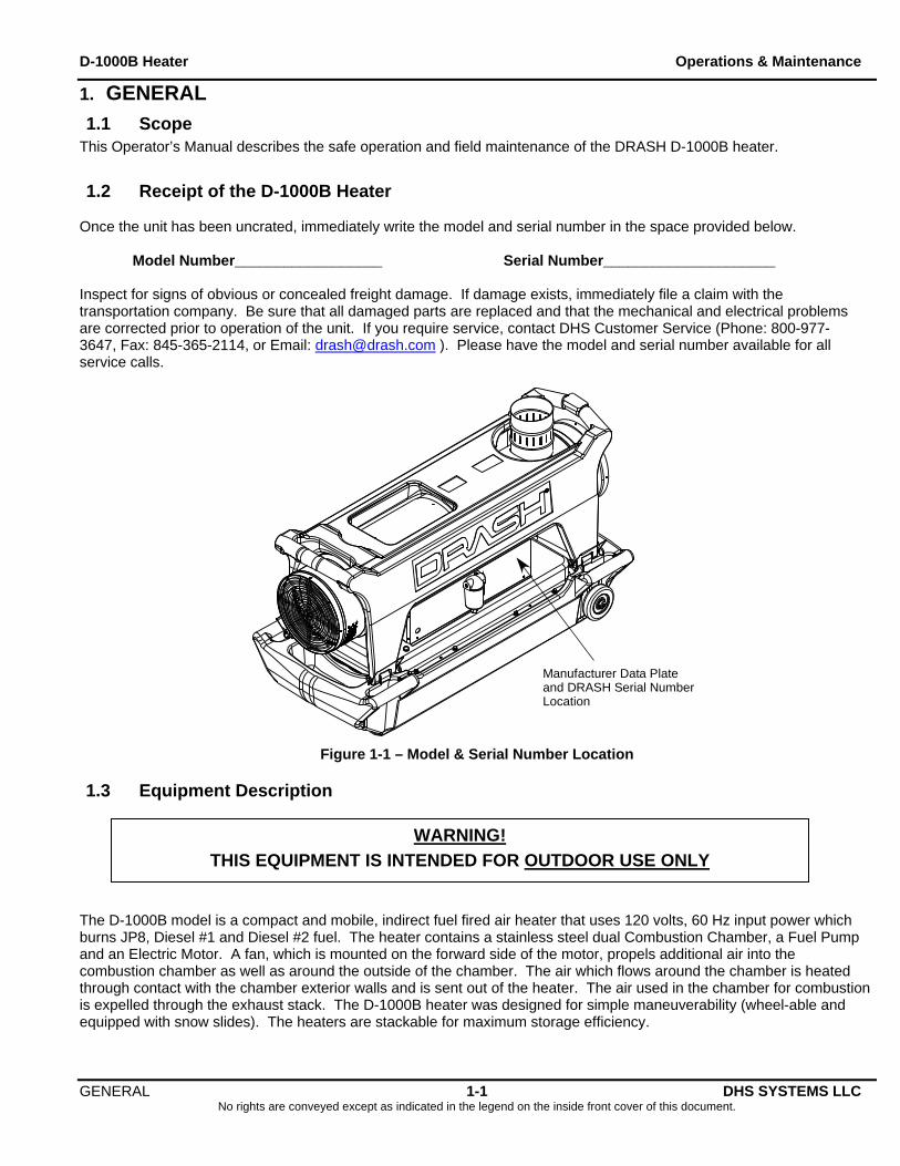
1.2 Receipt of the D-1000B Heater Once the unit has been uncrated, immediately write the model and serial number in the space provided below. Model Number__________________ Serial Number_____________________ Inspect for signs of obvious or concealed freight damage. If damage exists, immediately file a claim with the transportation company. Be sure that all damaged parts are replaced and that the mechanical and electrical problems are corrected prior to operation of the unit. If you require service, contact DHS Customer Service (Phone: 800-977-3647, Fax: 845-365-2114, or Email: [email protected] ). Please have the model and serial number available for all service calls.
Manufacturer Data Plateand DRASH Serial NumberLocation
Figure 1-1 – Model & Serial Number Location
1.3 Equipment Description
THIS EQUIPMENT IS INTENDED FOR OUTDOOR USE ONLY
WARNING!
The D-1000B model is a compact and mobile, indirect fuel fired air heater that uses 120 volts, 60 Hz input power which burns JP8, Diesel #1 and Diesel #2 fuel. The heater contains a stainless steel dual Combustion Chamber, a Fuel Pump and an Electric Motor. A fan, which is mounted on the forward side of the motor, propels additional air into the combustion chamber as well as around the outside of the chamber. The air which flows around the chamber is heated through contact with the chamber exterior walls and is sent out of the heater. The air used in the chamber for combustion is expelled through the exhaust stack. The D-1000B heater was designed for simple maneuverability (wheel-able and equipped with snow slides). The heaters are stackable for maximum storage efficiency.
GENERAL 1-1 DHS SYSTEMS LLC No rights are conveyed except as indicated in the legend on the inside front cover of this document.
D-1000B Heater Operations & Maintenance
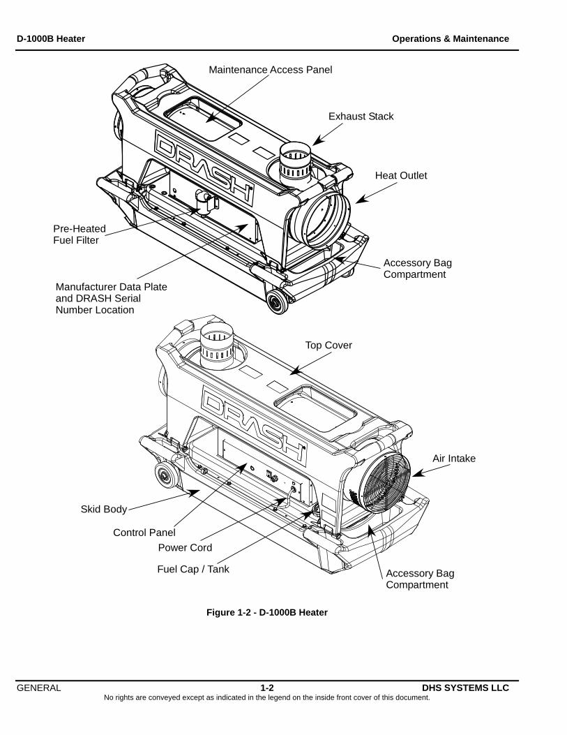
Maintenance Access Panel
Exhaust Stack
Heat Outlet
Skid Body
Pre-HeatedFuel Filter
Manufacturer Data Plateand DRASH SerialNumber Location
Top Cover
Air Intake
Fuel Cap / Tank
Power Cord
Control Panel
Accessory BagCompartment
Accessory BagCompartment
Figure 1-2 - D-1000B Heater
GENERAL 1-2 DHS SYSTEMS LLC No rights are conveyed except as indicated in the legend on the inside front cover of this document.
D-1000B Heater Operations & Maintenance
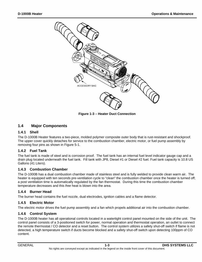
ACCESSORY BAG
Figure 1-3 – Heater Duct Connection
1.4 Major Components
1.4.1 Shell The D-1000B Heater features a two-piece, molded polymer composite outer body that is rust-resistant and shockproof. The upper cover quickly detaches for service to the combustion chamber, electric motor, or fuel pump assembly by removing four pins as shown in Figure 5-1.
1.4.2 Fuel Tank The fuel tank is made of steel and is corrosion proof. The fuel tank has an internal fuel level indicator gauge cap and a drain plug located underneath the fuel tank. Fill tank with JP8, Diesel #1 or Diesel #2 fuel. Fuel tank capacity is 10.8 US Gallons (41 Liters).
1.4.3 Combustion Chamber The D-1000B has a dual combustion chamber made of stainless steel and is fully welded to provide clean warm air. The heater is equipped with ten seconds pre-ventilation cycle to “clean” the combustion chamber once the heater is turned off; a post ventilation time is automatically regulated by the fan thermostat. During this time the combustion chamber temperature decreases and this free heat is blown into the area.
1.4.4 Burner Head The burner head contains the fuel nozzle, dual electrodes, ignition cables and a flame detector.
1.4.5 Electric Motor The electric motor drives the fuel pump assembly and a fan which propels additional air into the combustion chamber.
1.4.6 Control System The D-1000B heater has all operational controls located in a watertight control panel mounted on the side of the unit. The control panel consists of a 3-positioned switch for power, normal operation and thermostat operation, an outlet to connect the remote thermostat / CO detector and a reset button. The control system utilizes a safety shut-off switch if flame is not detected, a high temperature switch if ducts become blocked and a safety shut-off switch upon detecting 100ppm of CO content.
GENERAL 1-3 DHS SYSTEMS LLC No rights are conveyed except as indicated in the legend on the inside front cover of this document.
D-1000B Heater Operations & Maintenance
GENERAL 1-4 DHS SYSTEMS LLC No rights are conveyed except as indicated in the legend on the inside front cover of this document.
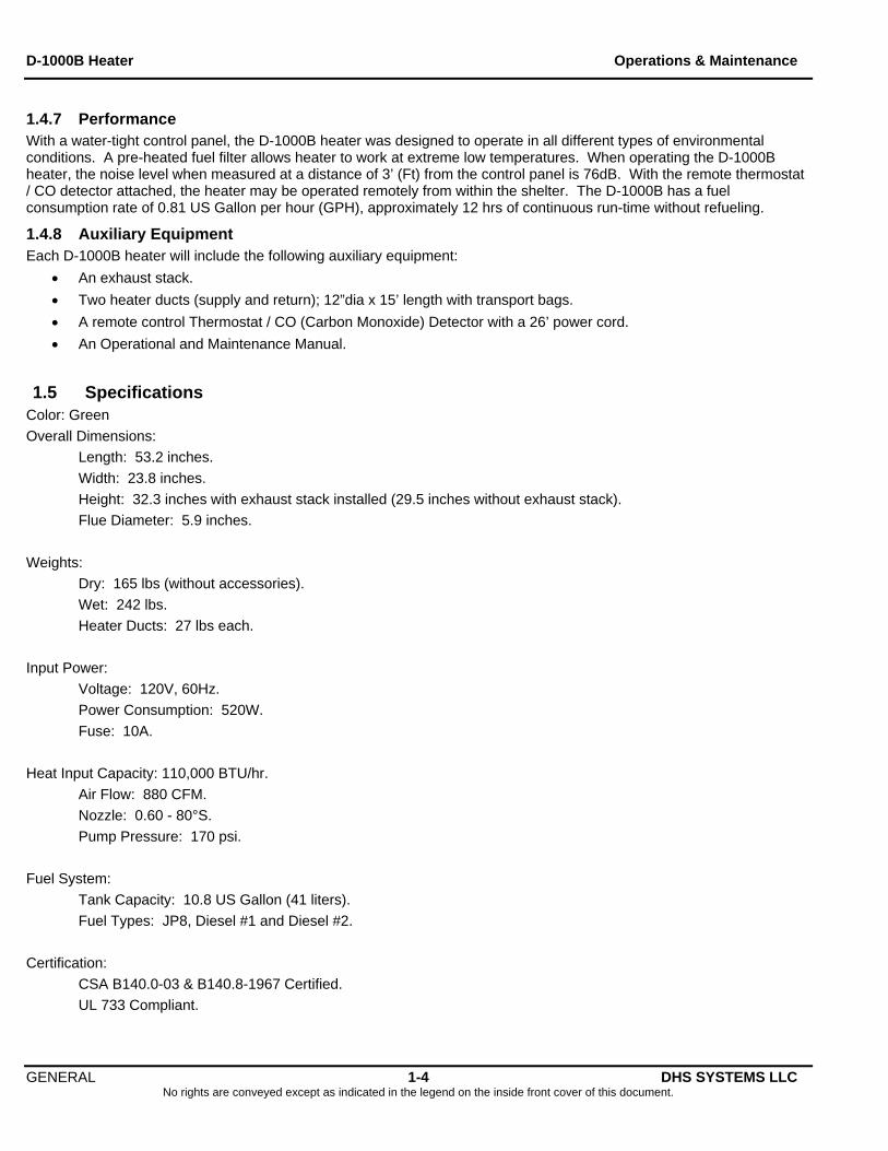
1.4.7 Performance With a water-tight control panel, the D-1000B heater was designed to operate in all different types of environmental conditions. A pre-heated fuel filter allows heater to work at extreme low temperatures. When operating the D-1000B heater, the noise level when measured at a distance of 3’ (Ft) from the control panel is 76dB. With the remote thermostat / CO detector attached, the heater may be operated remotely from within the shelter. The D-1000B has a fuel consumption rate of 0.81 US Gallon per hour (GPH), approximately 12 hrs of continuous run-time without refueling.
1.4.8 Auxiliary Equipment Each D-1000B heater will include the following auxiliary equipment:
An exhaust stack.
Two heater ducts (supply and return); 12”dia x 15’ length with transport bags.
A remote control Thermostat / CO (Carbon Monoxide) Detector with a 26’ power cord.
An Operational and Maintenance Manual.
1.5 Specifications Color: Green
Overall Dimensions:
Length: 53.2 inches.
Width: 23.8 inches.
Height: 32.3 inches with exhaust stack installed (29.5 inches without exhaust stack).
Flue Diameter: 5.9 inches.
Weights:
Dry: 165 lbs (without accessories).
Wet: 242 lbs.
Heater Ducts: 27 lbs each.
Input Power:
Voltage: 120V, 60Hz.
Power Consumption: 520W.
Fuse: 10A.
Heat Input Capacity: 110,000 BTU/hr.
Air Flow: 880 CFM.
Nozzle: 0.60 - 80°S.
Pump Pressure: 170 psi.
Fuel System:
Tank Capacity: 10.8 US Gallon (41 liters).
Fuel Types: JP8, Diesel #1 and Diesel #2.
Certification:
CSA B140.0-03 & B140.8-1967 Certified.
UL 733 Compliant.
D-1000B Heater Operations & Maintenance
2. SAFETY
2.1 Scope This chapter contains general information for the safe operation and maintenance of the D-1000B heater.
The cautions and warnings point out known conditions that are potentially hazardous. However, no manual can cover every possible situation. If in doubt, contact DHS.
Before calling DHS for assistance, please identify the heater by its DRASH assigned serial number, (see Section 1.2 Receipt of your D-1000B Heater) or the serial number is located on the Manufacturer decal. (See Figure 1-1).
Service and repairs should be performed only by authorized DHS technicians.
2.2 Qualified Personnel For the purposes of this manual, a qualified person is one who is familiar with this manual, the operation of the specific equipment and the hazards involved in operation and maintenance. This manual is not intended to be a substitute for proper training. We strongly recommend that operators receive training directly from DHS.
Phone: 800-977-3647
Fax: 845-365-2114
Email: [email protected]
IMPORTANT READ ALL OF THE INFORMATION CONTAINED IN THIS MANUAL BEFORE
OPERATING THE HEATER.
DHS Systems Contact Information
2.3 Signal Words and Labels Signal words and labels are used throughout this manual. The words and symbols convey the following advice:
2.3.1 Danger Danger refers to immediate hazards that will result in severe personal injury or death.
2.3.2 Warning Warning refers to a hazard or unsafe method or practice that may result in severe personal injury or death.
2.3.3 Caution Caution refers to a hazard or unsafe method or practice that may result in equipment damage or personal injury.
2.3.4 Important Important refers to a hazard or unsafe method or practice that can result in equipment damage.
2.4 General Precautions PLEASE REMEMBER SAFETY FIRST. If you are not sure of the instructions or procedures, contact DHS before continuing.
This manual emphasizes the safety precautions necessary during the operation and maintenance of your heater. Each section has caution and warning messages. These messages are for your safety and the safety of the equipment involved. If any of the cautions or warnings is not readily understood, contact DHS before proceeding.
When an abnormal condition is observed and procedures in the manual do not specifically cover the condition, work should be stopped. Contact DHS for assistance. An authorized DHS technician will provide guidance on the abnormal condition before any work can be continued.
SAFETY 2-1 DHS SYSTEMS LLC No rights are conveyed except as indicated in the legend on the inside front cover of this document.
D-1000B Heater Operations & Maintenance
2.4.1 Heater The following safety precautions should be observed:
The D-1000B heater must be used OUTDOORS ONLY.
Always follow local ordinances and codes when using this heater.
Always remove the fabric covers from each end of the heater before operating.
Operate the heater outdoors; upright with the exhaust stack attached and away from flammable or explosive materials (the minimum distance must be 6.5 ft / 2 m).
Ensure fire extinguisher / equipment is readily available.
Unplug heater when not in use.
Before performing any maintenance or repair work, you must:
Turn the power switch to the off position.
Wait for the heater to cool down.
Unplug the heater from the power supply.
These safety precautions are necessary to prevent serious personal injury or death.
Keep the heater enclosure clean and cleared of any debris within the shell.
Ensure the stack and ducts are clear of any obstructions that would restrict airflow.
Do not operate heater without the top cover properly installed.
Do not operate the heater without the fan properly installed.
Ensure your body and clothing stay clear of all moving parts.
Immediately stop the heater and fix any fuel leaks.
Do not perform maintenance while the heater is operating.
CAUTION Keep all solvents, cleaners or flammable liquids away. Adequate ventilation must be available. Avoid breathing vapors. Avoid fire, explosion, and any other health hazards. Always use protective equipment to prevent personal injuries to the head, face, eyes, hands, and feet.
2.4.2 Safety Protections The D-1000B heater has the following safety devices installed:
Flame Detector Safety Shut-off Switch: In case of the flame extinguishing, the safety shut-off switch will cut in and stop the heater; at the same time the reset button will illuminate (See Figure 4-1, Item #1).
High Temperature Limit Switch: If the heater ducts become blocked (exceeding 250°F), the high temperature limit switch shuts down the heater.
CO Safety Shut-off Switch: This safety shut-off switch will shut down the heater upon detecting 100 PPM of Carbon Monoxide.
Thermostatic Safety Switch (TSS): When the heater is switched off, the TSS assures that the fan continues to run until the surface temperature of the combustion chamber drops, assuring a safe restart.
Fan Pressure Switch: When the fan stops working, this device disables ignition and cuts fuel supply.
SAFETY 2-2 DHS SYSTEMS LLC No rights are conveyed except as indicated in the legend on the inside front cover of this document.
D-1000B Heater Operations & Maintenance
3. STORAGE & TRANSPORT
3.1 Scope The D-1000B heater is designed for outdoor use only. No special packaging is required for storage or transport.
3.1.1 Transport and Storage
IMPORTANT The owner of the Heater is responsible for investigating local ordinances, applicable laws, codes and regulations concerning the transportation of Diesel fuel and or JP8.
Before the D-1000B heater is transported or placed in storage, the heater must be totally cooled off. Before moving the heater, the heater’s power switch must be in the OFF (O) position and unplugged. Ensure the following equipment is installed and attached to the heater before transporting or storing.
Store the exhaust stack inside the fabric cover with straps which covers the heat outlet.
Protective (fabric) covers are placed on the air inlet and heat outlet area.
Repack and place the Accessory Bag with the Operator’s Manual and Remote Thermostat / CO Detector into the accessory bag compartment. (See Figure 1-1).
Ensure the fuel cap is securely tightened.
3.2 Storage
3.2.1 Before storing Always repack the accessory bag with the operators’ manual and remote thermostat / CO detector before storage. Place the exhaust stack inside the fabric cover with straps and secure exhaust stack with straps. Reinstall all protective covers and replace accessories bag into compartment in the base of the heater, see Figure 1-1. Drain the fuel from the tank using the following steps:
1. Remove the four quick release pins.
2. Remove the top cover.
3. Carefully lift the heater up and remove the skid body.
4. Using a suitable container, remove drain plug and drain fuel. (You may need to lift the opposite end from drain plug to ensure all fuel is drained).
5. Reinstall drain plug.
6. Lift the heater and place back into the skid body.
7. Reinstall top cover and four quick release pins.
3.2.2 After storing 1. Remove all fabric covers and Accessories Bag from heater.
2. Install exhaust stack.
3. Add fuel; run the heater outdoors in accordance to the start up procedures for 10 minutes.
4. Service heater if any problems are noted.
3.3 Shipping Before shipping the D-1000B heater, ensure the power switch is in the OFF (O) position (the center position), the exhaust stack is securely fastened inside the heat outlet fabric cover, the operators’ manual and remote thermostat / CO detector are placed inside the Accessories Bag and placed in the base of the heater. Ensure all protective covers are in place. This heater should be shipped in an enclosed box and securely fastened to a pallet.
STORAGE & TRANSPORT 3-1 DHS SYSTEMS LLC No rights are conveyed except as indicated in the legend on the inside front cover of this document.
D-1000B Heater Operations & Maintenance
STORAGE & TRANSPORT 3-2 DHS SYSTEMS LLC No rights are conveyed except as indicated in the legend on the inside front cover of this document.
THIS PAGE INTENTIONALLY LEFT BLANK
D-1000B Heater Operations & Maintenance
4. OPERATIONS
4.1 General The following chapter contains general information for operating the D-1000B heater.
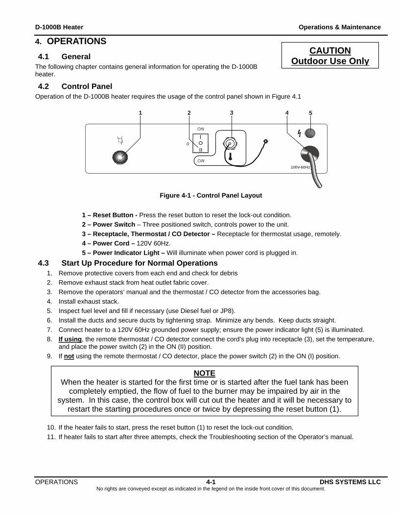
4.2 Control Panel Operation of the D-1000B heater requires the usage of the control panel shown in Figure 4.1
OPERATIONS 4-1 DHS SYSTEMS LLC No rights are conveyed except as indicated in the legend on the inside front cover of this document.
1 32 54
100V-60Hz
II
I
Figure 4-1 - Control Panel Layout
1 – Reset Button - Press the reset button to reset the lock-out condition.
2 – Power Switch – Three positioned switch, controls power to the unit.
3 – Receptacle, Thermostat / CO Detector – Receptacle for thermostat usage, remotely.
4 – Power Cord – 120V 60Hz.
5 – Power Indicator Light – Will illuminate when power cord is plugged in.
4.3 Start Up Procedure for Normal Operations 1. Remove protective covers from each end and check for debris
2. Remove exhaust stack from heat outlet fabric cover.
3. Remove the operators’ manual and the thermostat / CO detector from the accessories bag.
4. Install exhaust stack.
5. Inspect fuel level and fill if necessary (use Diesel fuel or JP8).
6. Install the ducts and secure ducts by tightening strap. Minimize any bends. Keep ducts straight.
7. Connect heater to a 120V 60Hz grounded power supply; ensure the power indicator light (5) is illuminated.
8. If using, the remote thermostat / CO detector connect the cord’s plug into receptacle (3), set the temperature, and place the power switch (2) in the ON (II) position.
9. If not using the remote thermostat / CO detector, place the power switch (2) in the ON (I) position.
CAUTION Outdoor Use Only
NOTE When the heater is started for the first time or is started after the fuel tank has been
completely emptied, the flow of fuel to the burner may be impaired by air in the system. In this case, the control box will cut out the heater and it will be necessary to
restart the starting procedures once or twice by depressing the reset button (1).
10. If the heater fails to start, press the reset button (1) to reset the lock-out condition.
11. If heater fails to start after three attempts, check the Troubleshooting section of the Operator’s manual.
D-1000B Heater Operations & Maintenance
4.4 Start Up Procedures for Cold Weather Operations 1. Connect heater to a 120V 60Hz grounded power supply for 15 minutes to pre-heat fuel filter.
2. Remove protective covers from each end and check for debris.
3. Remove exhaust stack from heat outlet fabric cover.
4. Remove the operators’ manual and the thermostat / CO detector from the accessories bag.
5. Install exhaust stack.
6. Install the ducts and secure ducts by tightening strap. Minimize any bends. Keep ducts straight
7. If using, the remote thermostat / CO detector connect the cord‘s plug into receptacle (3), set the temperature, and place the power switch (2) in the ON (II) position.
8. If not using the remote thermostat / CO detector, place the power switch (2) in the ON (I) position.
9. If the heater fails to start, press the reset button (1) to reset the lock-out condition.
10. If heater fails to start after two attempts, check the Troubleshooting section of the Operator’s manual.
4.5 Start Up Procedures for High Altitude Operations (4500’/1500m) 1. Refer to Section 5.4.1 to gain internal access to the burner head.
2. Refer to Figure 5-9; remove rubber grommet (68) from burner flange (61).
3. Secure maintenance access panel and reinstall top cover.
4. Refer to Section 4.3 or 4.4 for start up procedures depending on conditions.
4.6 Shut Down Procedure
1. Place the power switch (2) to the OFF (O) position or if used set the thermostat to the lowest setting. By placing the power switch in the OFF (O) position or setting the thermostat to the lowest setting, the flame will go out, but the fan continues to spin for approximately 90 seconds cooling the combustion chamber.
CAUTION
Surfaces and pieces may be hot.
2. Remove the exhaust stack and heater duct. (Ensure items are cool before removing).
3. Repack the exhaust stack inside the heat outlet fabric cover.
4. Repack operator’s manual and remote thermostat / CO detector into the accessories bag.
5. Return the accessory bag to its compartment in the base of the heater.
6. Repack heater ducts into transport bag.
7. Replace fabric covers on each end of the heater.
OPERATIONS 4-2 DHS SYSTEMS LLC No rights are conveyed except as indicated in the legend on the inside front cover of this document.
D-1000B Heater Operations & Maintenance
4.7 Filling the Fuel Tank
WARNING!
DO NOT USE GASOLINE. USING ANY UNAPPROVED FUELS FOR THE HEATER COULD RESULT IN DAMAGE TO THE HEATER AND / OR PERSONAL INJURY.
Ensure the power switch is in the OFF (O) position. It is recommended to allow 5 minutes for the D-1000B heater to cool before refueling.
1. Unplug the power cord from the power supply.
2. Unscrew the fuel cap and refuel the heater. (Use JP8, Diesel #1 or Diesel #2 fuel).
3. Reinstall the fuel cap. Clean any spills that may have occurred.
4. Reconnect the heater to the power supply; resume heater usage by placing the power switch to the ON (II) position if using the remote thermostat or to the ON (I) position if not using the remote thermostat.
OPERATIONS 4-3 DHS SYSTEMS LLC No rights are conveyed except as indicated in the legend on the inside front cover of this document.
D-1000B Heater Operations & Maintenance
OPERATIONS 4-4 DHS SYSTEMS LLC No rights are conveyed except as indicated in the legend on the inside front cover of this document.
THIS PAGE INTENTIONALLY LEFT BLANK
D-1000B Heater Operations & Maintenance
MAINTENANCE, and REPAIR PROCEDURES 5-1 DHS SYSTEMS LLC No rights are conveyed except as indicated in the legend on the inside front cover of this document.
5. MAINTENANCE, and REPAIR PROCEDURES
5.1 General This chapter contains general information for operator-level, qualified personnel. A qualified person is one who is familiar with this manual, the operation of the D-1000B heater; the hazard involved in its operation and maintenance, and has been certified by the DHS Training Program. This chapter also describes the procedures for both periodic and daily maintenance.
Periodic maintenance at the five-year interval is not covered in this manual; maintenance at this interval should be performed by authorized DHS technicians. Maintenance and service contracts can be arranged with DHS Logistics Co. Parts for maintenance and service can also be obtained from DHS Logistics Co. Please contact DHS for more information (Phone: 800-977-3647, Fax: 845-365-2114 or E-mail: [email protected] ).
This manual is not intended to be a substitute for proper training. We strongly recommend that operators receive training directly from DHS.
The cautions and warnings point out known conditions that are potentially hazardous. Note that no manual can cover every possible situation. If in doubt, contact DHS.
Before calling DHS for assistance, please identify the heater by its DRASH serial number. The serial number is located on the control panel side of the heater as shown in Figure 1-1.
Only authorized DHS technicians should perform Service and repairs beyond the scope of this manual.
5.2 Maintenance This section describes preventive and regular maintenance schedules. Preventive and regular maintenance will ensure a long trouble free life to your heater.
5.2.1 Periodic Maintenance Periodic maintenance of the heater is necessary and must be part of the daily routine of operating the heater. Maintenance activities should be performed at the following periodic intervals:
5.2.2 Daily Maintenance Check the following points prior to starting the heater:
Ensure that both fabric covers have been removed.
Inspect both ends and the exhaust stack port for any debris. Remove debris.
Install heater ducts, secure by tightening strap. Minimize any bends. Keep ducts straight.
Verify fuel tank is full.
Verify that the exhaust stack is properly installed.
5.2.3 50 Hour Maintenance After every 50 hours of operation, perform the following maintenance.
Remove, disassemble and inspect the pre-heated fuel filter.
Clean the fuel filter with clean fuel.
Remove top cover and clean the heaters’ exterior.
Loosen and slide the maintenance access panel rearward.
Using compressed air, clean the interior area.
Clean the fan blade.
Check for leaks.
Check for proper attachment of High Temp (H.T.) connectors to electrodes.
Remove burner assembly, clean and check electrode setting; adjust according to Step 5.4.9
D-1000B Heater Operations & Maintenance
5.2.4 Annual Maintenance Check all nuts, bolts, fittings, and connections for looseness. Tighten as required.
Clean or replace the fuel filter.
Drain and flush the fuel tank.
Remove burner assembly, clean, and adjust electrode setting.
Remove and replace fuel nozzle.
5.3 Servicing the Fuel Tank During regular scheduled maintenance or when the fuel tank becomes contaminated or dirty, the fuel tank can be cleaned by removing the drain plug and draining the fuel. Using approximately four gallons (15 liters) of clean Diesel or JP8 fuel, the fuel tank can be flushed. If a leak is detected, the fuel tank is a non-repairable item, it must be replaced. For information on how to replace the fuel tank, please contact DHS.
5.4 Repairs Procedures
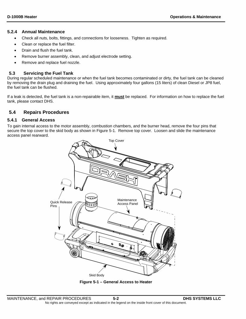
5.4.1 General Access To gain internal access to the motor assembly, combustion chambers, and the burner head, remove the four pins that secure the top cover to the skid body as shown in Figure 5-1. Remove top cover. Loosen and slide the maintenance access panel rearward.
Top Cover
MaintenanceAccess Panel
Skid Body
Quick ReleasePins
Figure 5-1 – General Access to Heater
MAINTENANCE, and REPAIR PROCEDURES 5-2 DHS SYSTEMS LLC No rights are conveyed except as indicated in the legend on the inside front cover of this document.
D-1000B Heater Operations & Maintenance
NOTE!
In the following Repair Procedures, the numbers in parentheses refer to item numbers listed in Chapter 8, Illustrated Parts Breakdown diagram on page 8-1 or
otherwise noted.
5.4.2 Removal and Installation Electric Motor Assembly 5.4.2.1 Removal procedures:
1. Disconnect power cord and allow heater to cool.
2. Remove the four quick release pins as shown in Figure 5-1; remove top exterior cover.
3. Using an 8mm nut driver, remove the upper heat shield (5) by removing six screws (79) and two sheet metal screws (78). Remove heat shield and set aside.
4. Using a 4mm Allen wrench, loosen set screw (92) and remove fan blade (15).
5. Disconnect the three wires from the fuel solenoid (71).
6. Using a 15mm open end wrench, loosen and disconnect at the fuel pump, the fuel supply line (18) to the fuel filter and fuel return line (22B) to the fuel tank.
7. Using a 13mm open end wrench, loosen and disconnect the fuel feed hose (65) at the fuel pump to the burner head (61).
8. Using a 2.5mm Allen wrench, loosen (DO NOT REMOVE) three set screws on the fuel pump collar to the back of the electric motor; remove fuel pump (70) from electric motor (10).
9. Using a Phillips screwdriver, loosen and remove two control panel mounting screws (81); pull out the control panel assembly (29) from the base (30) to expose the terminal boards.
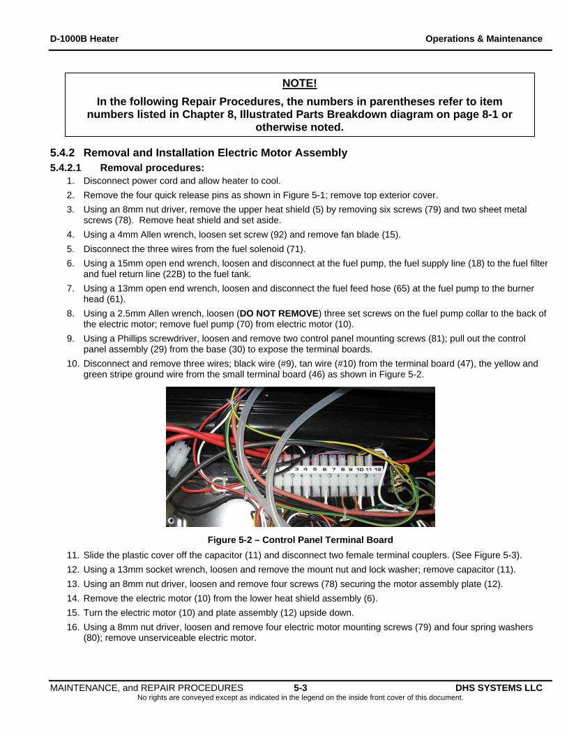
10. Disconnect and remove three wires; black wire (#9), tan wire (#10) from the terminal board (47), the yellow and green stripe ground wire from the small terminal board (46) as shown in Figure 5-2.
Figure 5-2 – Control Panel Terminal Board
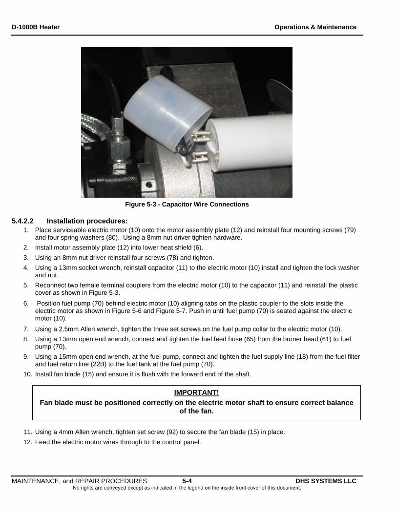
11. Slide the plastic cover off the capacitor (11) and disconnect two female terminal couplers. (See Figure 5-3).
12. Using a 13mm socket wrench, loosen and remove the mount nut and lock washer; remove capacitor (11).
13. Using an 8mm nut driver, loosen and remove four screws (78) securing the motor assembly plate (12).
14. Remove the electric motor (10) from the lower heat shield assembly (6).
15. Turn the electric motor (10) and plate assembly (12) upside down.
16. Using a 8mm nut driver, loosen and remove four electric motor mounting screws (79) and four spring washers (80); remove unserviceable electric motor.
MAINTENANCE, and REPAIR PROCEDURES 5-3 DHS SYSTEMS LLC No rights are conveyed except as indicated in the legend on the inside front cover of this document.
D-1000B Heater Operations & Maintenance
Figure 5-3 - Capacitor Wire Connections
5.4.2.2 Installation procedures:
1. Place serviceable electric motor (10) onto the motor assembly plate (12) and reinstall four mounting screws (79) and four spring washers (80). Using a 8mm nut driver tighten hardware.
2. Install motor assembly plate (12) into lower heat shield (6).
3. Using an 8mm nut driver reinstall four screws (78) and tighten.
4. Using a 13mm socket wrench, reinstall capacitor (11) to the electric motor (10) install and tighten the lock washer and nut.
5. Reconnect two female terminal couplers from the electric motor (10) to the capacitor (11) and reinstall the plastic cover as shown in Figure 5-3.
6. Position fuel pump (70) behind electric motor (10) aligning tabs on the plastic coupler to the slots inside the electric motor as shown in Figure 5-6 and Figure 5-7. Push in until fuel pump (70) is seated against the electric motor (10).
7. Using a 2.5mm Allen wrench, tighten the three set screws on the fuel pump collar to the electric motor (10).
8. Using a 13mm open end wrench, connect and tighten the fuel feed hose (65) from the burner head (61) to fuel pump (70).
9. Using a 15mm open end wrench, at the fuel pump, connect and tighten the fuel supply line (18) from the fuel filter and fuel return line (22B) to the fuel tank at the fuel pump (70).
10. Install fan blade (15) and ensure it is flush with the forward end of the shaft.
IMPORTANT!
Fan blade must be positioned correctly on the electric motor shaft to ensure correct balance of the fan.
11. Using a 4mm Allen wrench, tighten set screw (92) to secure the fan blade (15) in place.
12. Feed the electric motor wires through to the control panel.
MAINTENANCE, and REPAIR PROCEDURES 5-4 DHS SYSTEMS LLC No rights are conveyed except as indicated in the legend on the inside front cover of this document.
D-1000B Heater Operations & Maintenance
Electric Motor Installation Procedures Continued
13. Connect the electric motor wire harness’ three wires; black wire (#9), tan wire (#10) on the terminal board (47), the yellow and green stripe ground wire on the small terminal board (46).
14. Reinstall the control panel assembly (29). Using a 8mm nut driver, install two screws (81) and tighten.
15. Reinstall upper heat shield (5).
16. Using an 8mm nut driver install and tighten six screws (79) and two sheet metal screws (78).
17. Reinstall top exterior cover and install the four quick release pins (see Figure 5-1).
18. Connect power cord to a ground power supply.
19. Perform an operational test and check for leaks. (See Chapter 6).
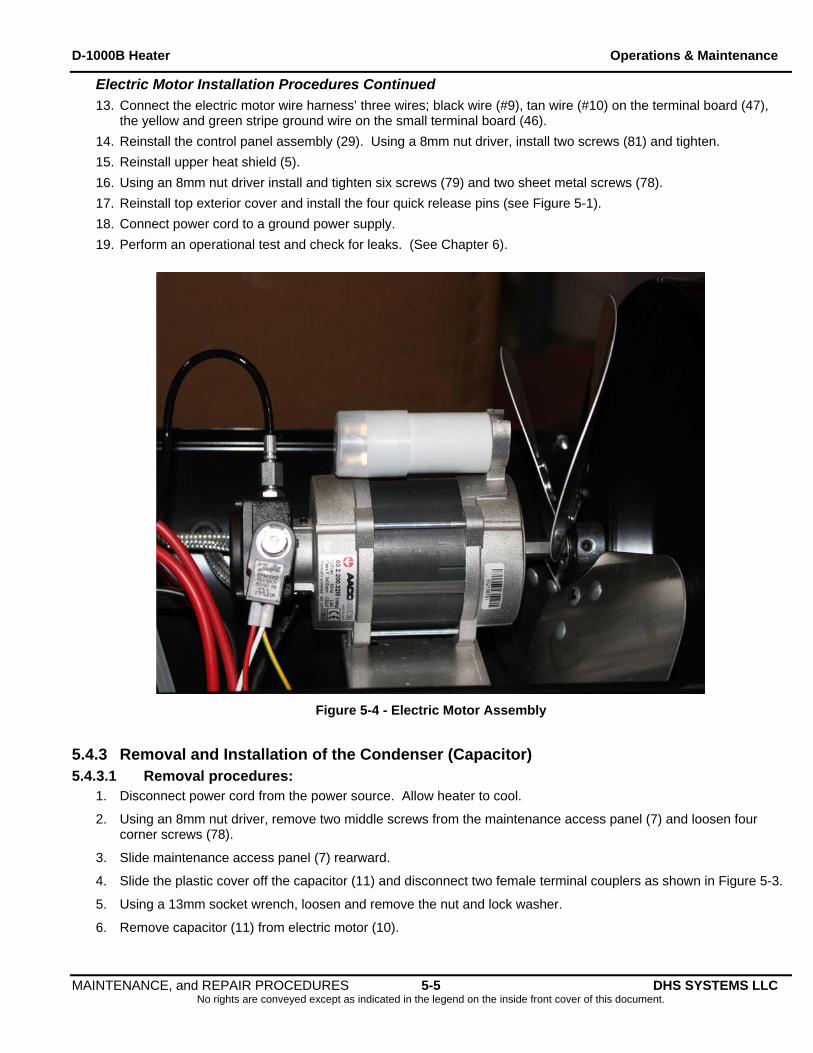
Figure 5-4 - Electric Motor Assembly
5.4.3 Removal and Installation of the Condenser (Capacitor) 5.4.3.1 Removal procedures:
1. Disconnect power cord from the power source. Allow heater to cool.
2. Using an 8mm nut driver, remove two middle screws from the maintenance access panel (7) and loosen four corner screws (78).
3. Slide maintenance access panel (7) rearward.
4. Slide the plastic cover off the capacitor (11) and disconnect two female terminal couplers as shown in Figure 5-3.
5. Using a 13mm socket wrench, loosen and remove the nut and lock washer.
6. Remove capacitor (11) from electric motor (10).
MAINTENANCE, and REPAIR PROCEDURES 5-5 DHS SYSTEMS LLC No rights are conveyed except as indicated in the legend on the inside front cover of this document.
D-1000B Heater Operations & Maintenance
5.4.3.2 Installation procedures: 1. Install capacitor (11) onto the electric motor (10).
2. Using a 13mm socket wrench, install lock washer and nut. Tighten hardware.
3. Reconnect the two female terminal couplers and slide plastic cover over terminals.
4. Slide maintenance access panel (7) forward.
5. Using an 8mm nut driver, install two middle screws (78) and tighten all remaining hardware.
6. Test heater in accordance with operations manual. (See Chapter 6).
5.4.4 Removal and Installation of Fuel Filter 5.4.4.1 Removal procedures:
1. Disconnect power cord from the power source. Allow heater to cool.
2. Using a 19mm open end wrench, loosen and remove pre-heat probe from bottom of fuel filter assembly
3. Using a 10mm open end wrench, remove bolt, washer and o-ring from top of fuel filter assembly.
4. Using a suitable container, collect the fuel when removing the fuel filter assembly.
5. Remove, clean and inspect filter and discard all gaskets.
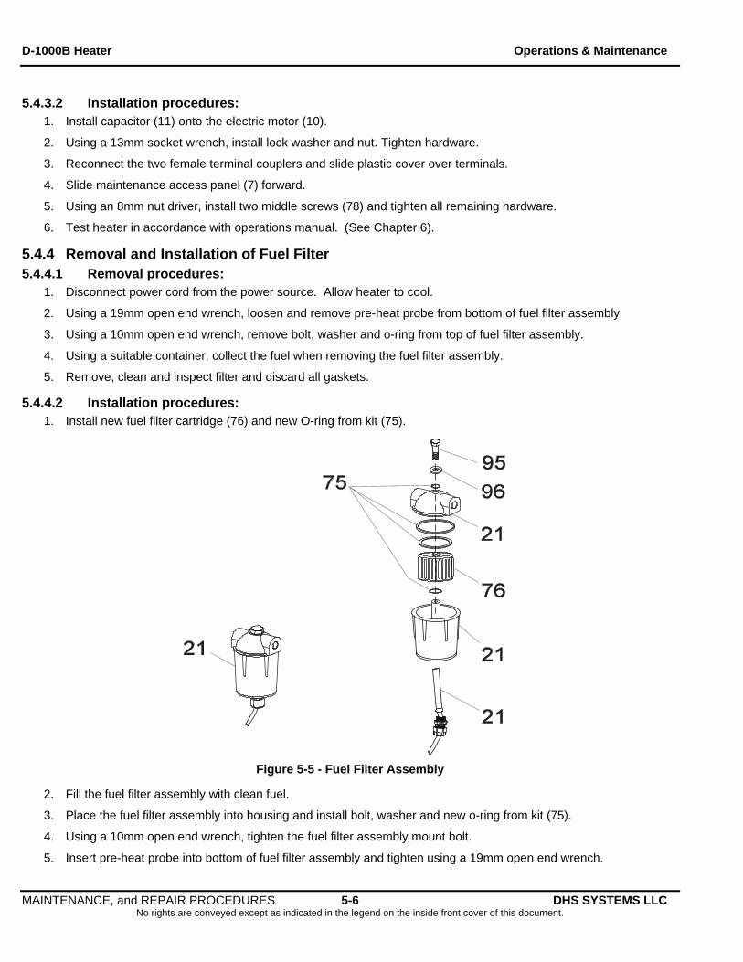
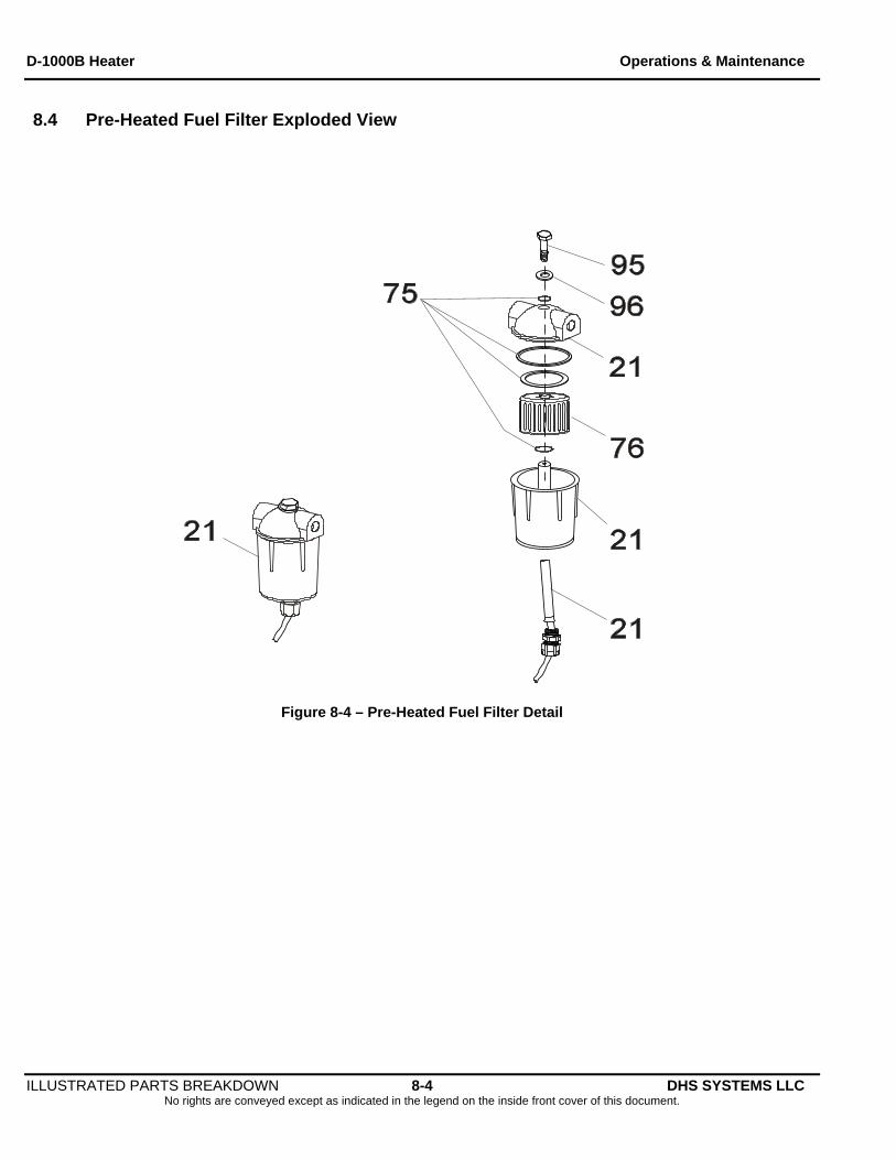
5.4.4.2 Installation procedures: 1. Install new fuel filter cartridge (76) and new O-ring from kit (75).
Figure 5-5 - Fuel Filter Assembly
2. Fill the fuel filter assembly with clean fuel.
3. Place the fuel filter assembly into housing and install bolt, washer and new o-ring from kit (75).
4. Using a 10mm open end wrench, tighten the fuel filter assembly mount bolt.
5. Insert pre-heat probe into bottom of fuel filter assembly and tighten using a 19mm open end wrench.
MAINTENANCE, and REPAIR PROCEDURES 5-6 DHS SYSTEMS LLC No rights are conveyed except as indicated in the legend on the inside front cover of this document.
D-1000B Heater Operations & Maintenance
MAINTENANCE, and REPAIR PROCEDURES 5-7 DHS SYSTEMS LLC No rights are conveyed except as indicated in the legend on the inside front cover of this document.
Fuel Filter Installation Procedures Continued:
6. Wipe up any fuel spills.
7. Connect heater to a power supply.
8. Test heater in accordance with operations manual (see Chapter 6) and check for fuel leaks.
5.4.5 Removal and Installation of Fuel Pump Assembly 5.4.5.1 Removal Procedures:
1. Disconnect power cord from power source and allow heater to cool.
2. Remove four quick release pins and remove top cover (see Figure 5-1).
3. Using a 8mm nut driver, remove the upper heat shield (5) by removing six screws (79) and two sheet metal screws (78); remove heat shield and set aside
4. Disconnect the fuel solenoid leads.
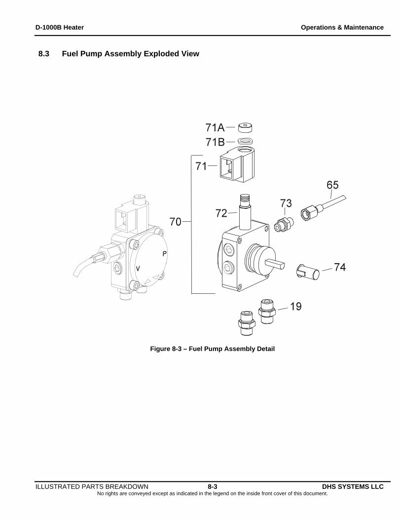
5. Using a 4mm Allen wrench, loosen and remove fuel solenoid cap nut (71A) and wave washer (71B) as shown in Figure 5-6.
6. Using a 13mm open end wrench, loosen and disconnect at the fuel pump (70) the fuel feed hose (65).
7. Using a 15mm open end wrench, loosen and disconnect at the fuel pump (70) the fuel supply line (18) and fuel return line (22B).
8. Using a 2.5mm Allen wrench, loosen (DO NOT REMOVE) three set screws on the fuel pump collar (see Figure 5-4); remove fuel pump from electric motor assembly.
5.4.5.2 Installation Procedures 1. Using a 15mm open end wrench, attach at the fuel pump (70) the fuel supply line (18) and fuel return line (22B).
2. Using a 13mm open end wrench, connect and tighten the fuel feed hose (65) from the burner head (61) to fuel pump (70).
3. Using a 4mm Allen wrench, attach fuel solenoid (71) wave washer (71B) and cap nut (71A) as shown in Figure 5-6.
4. Positioned fuel pump (70) behind electric motor (10) aligning tabs on the plastic coupler to the slots inside the electric motor as shown in Figure 5-6 and Figure 5-7. Push in until fuel pump (70) is seated against the electric motor (10).
5. Using a 2.5mm Allen wrench, tighten three set screws on the fuel pump collar to secure the fuel pump (70) to the electric motor (10) (see Figure 5-4).
6. Reconnect the fuel solenoid leads. Install heat shield (5).
7. Using an 8mm nut driver install and tighten six screws (79) and two sheet metal screws (78).
8. Install the top cover and four quick release pins as shown in Figure 5-1.
9. Test heater in accordance with the operations manual (see Chapter 6) and check for fuel leaks.
D-1000B Heater Operations & Maintenance
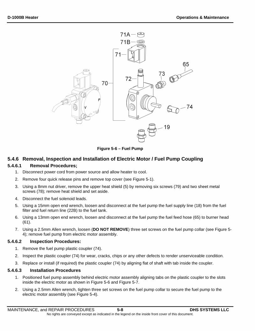
Figure 5-6 – Fuel Pump
5.4.6 Removal, Inspection and Installation of Electric Motor / Fuel Pump Coupling 5.4.6.1 Removal Procedures;
1. Disconnect power cord from power source and allow heater to cool.
2. Remove four quick release pins and remove top cover (see Figure 5-1).
3. Using a 8mm nut driver, remove the upper heat shield (5) by removing six screws (79) and two sheet metal screws (78); remove heat shield and set aside.
4. Disconnect the fuel solenoid leads.
5. Using a 15mm open end wrench, loosen and disconnect at the fuel pump the fuel supply line (18) from the fuel filter and fuel return line (22B) to the fuel tank.
6. Using a 13mm open end wrench, loosen and disconnect at the fuel pump the fuel feed hose (65) to burner head (61).
7. Using a 2.5mm Allen wrench, loosen (DO NOT REMOVE) three set screws on the fuel pump collar (see Figure 5-4); remove fuel pump from electric motor assembly.
5.4.6.2 Inspection Procedures:
1. Remove the fuel pump plastic coupler (74).
2. Inspect the plastic coupler (74) for wear, cracks, chips or any other defects to render unserviceable condition.
3. Replace or install (if required) the plastic coupler (74) by aligning flat of shaft with tab inside the coupler.
5.4.6.3 Installation Procedures
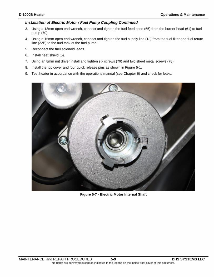
1. Positioned fuel pump assembly behind electric motor assembly aligning tabs on the plastic coupler to the slots inside the electric motor as shown in Figure 5-6 and Figure 5-7.
2. Using a 2.5mm Allen wrench, tighten three set screws on the fuel pump collar to secure the fuel pump to the electric motor assembly (see Figure 5-4).
MAINTENANCE, and REPAIR PROCEDURES 5-8 DHS SYSTEMS LLC No rights are conveyed except as indicated in the legend on the inside front cover of this document.
D-1000B Heater Operations & Maintenance
Installation of Electric Motor / Fuel Pump Coupling Continued
3. Using a 13mm open end wrench, connect and tighten the fuel feed hose (65) from the burner head (61) to fuel pump (70).
4. Using a 15mm open end wrench, connect and tighten the fuel supply line (18) from the fuel filter and fuel return line (22B) to the fuel tank at the fuel pump.
5. Reconnect the fuel solenoid leads.
6. Install heat shield (5).
7. Using an 8mm nut driver install and tighten six screws (79) and two sheet metal screws (78).
8. Install the top cover and four quick release pins as shown in Figure 5-1.
9. Test heater in accordance with the operations manual (see Chapter 6) and check for leaks.
Figure 5-7 - Electric Motor Internal Shaft
MAINTENANCE, and REPAIR PROCEDURES 5-9 DHS SYSTEMS LLC No rights are conveyed except as indicated in the legend on the inside front cover of this document.
D-1000B Heater Operations & Maintenance
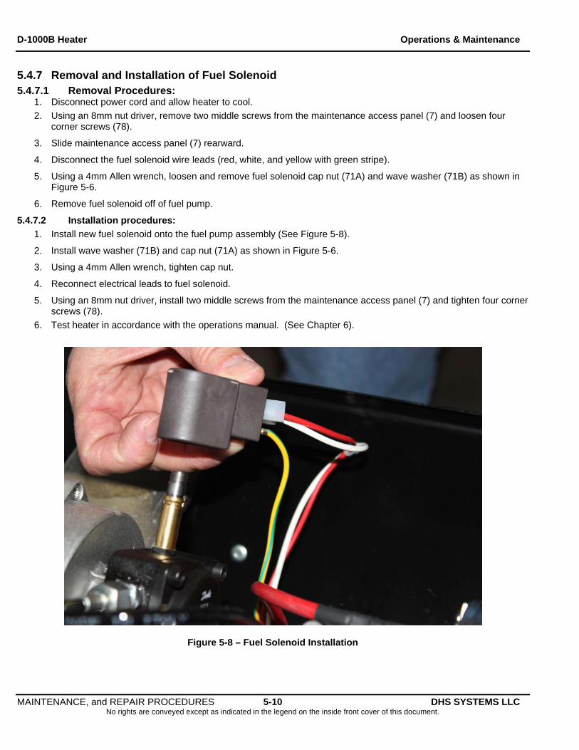
5.4.7 Removal and Installation of Fuel Solenoid 5.4.7.1 Removal Procedures:
1. Disconnect power cord and allow heater to cool.
2. Using an 8mm nut driver, remove two middle screws from the maintenance access panel (7) and loosen four corner screws (78).
3. Slide maintenance access panel (7) rearward.
4. Disconnect the fuel solenoid wire leads (red, white, and yellow with green stripe).
5. Using a 4mm Allen wrench, loosen and remove fuel solenoid cap nut (71A) and wave washer (71B) as shown in Figure 5-6.
6. Remove fuel solenoid off of fuel pump.
5.4.7.2 Installation procedures:
1. Install new fuel solenoid onto the fuel pump assembly (See Figure 5-8).
2. Install wave washer (71B) and cap nut (71A) as shown in Figure 5-6.
3. Using a 4mm Allen wrench, tighten cap nut.
4. Reconnect electrical leads to fuel solenoid.
5. Using an 8mm nut driver, install two middle screws from the maintenance access panel (7) and tighten four corner screws (78).
6. Test heater in accordance with the operations manual. (See Chapter 6).
Figure 5-8 – Fuel Solenoid Installation
MAINTENANCE, and REPAIR PROCEDURES 5-10 DHS SYSTEMS LLC No rights are conveyed except as indicated in the legend on the inside front cover of this document.
D-1000B Heater Operations & Maintenance
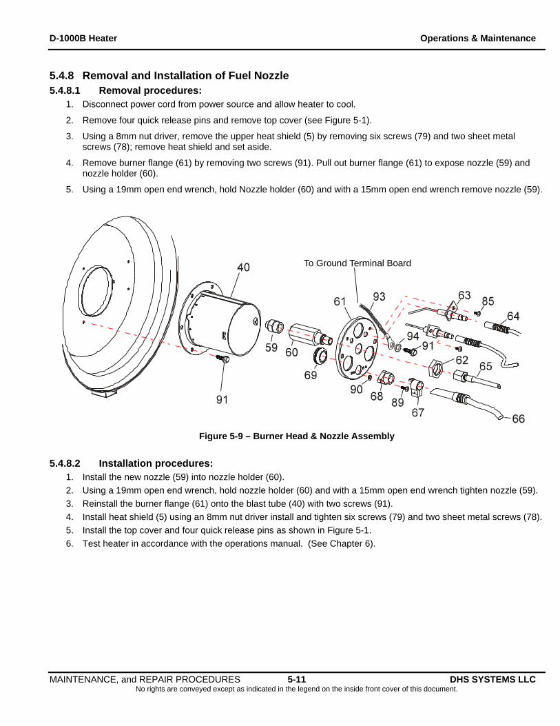
5.4.8 Removal and Installation of Fuel Nozzle 5.4.8.1 Removal procedures:
1. Disconnect power cord from power source and allow heater to cool.
2. Remove four quick release pins and remove top cover (see Figure 5-1).
3. Using a 8mm nut driver, remove the upper heat shield (5) by removing six screws (79) and two sheet metal screws (78); remove heat shield and set aside.
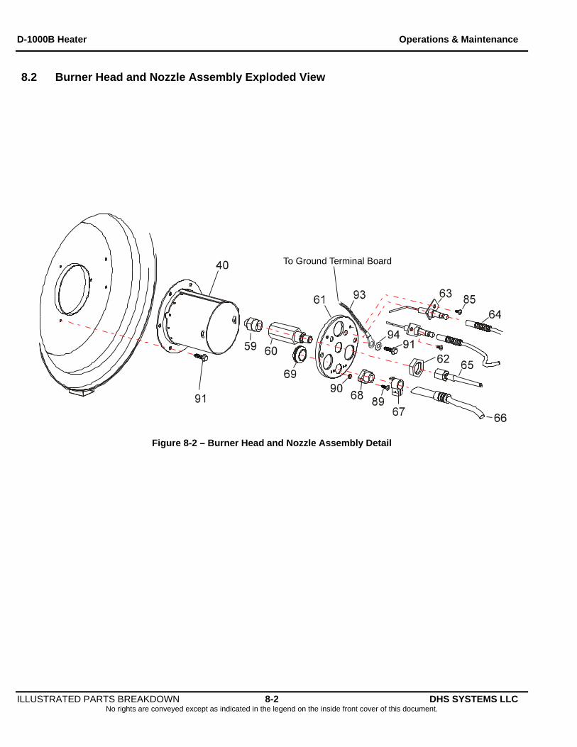
4. Remove burner flange (61) by removing two screws (91). Pull out burner flange (61) to expose nozzle (59) and nozzle holder (60).
5. Using a 19mm open end wrench, hold Nozzle holder (60) and with a 15mm open end wrench remove nozzle (59).
To Ground Terminal Board
Figure 5-9 – Burner Head & Nozzle Assembly
5.4.8.2 Installation procedures:
1. Install the new nozzle (59) into nozzle holder (60).
2. Using a 19mm open end wrench, hold nozzle holder (60) and with a 15mm open end wrench tighten nozzle (59).
3. Reinstall the burner flange (61) onto the blast tube (40) with two screws (91).
4. Install heat shield (5) using an 8mm nut driver install and tighten six screws (79) and two sheet metal screws (78).
5. Install the top cover and four quick release pins as shown in Figure 5-1.
6. Test heater in accordance with the operations manual. (See Chapter 6).
MAINTENANCE, and REPAIR PROCEDURES 5-11 DHS SYSTEMS LLC No rights are conveyed except as indicated in the legend on the inside front cover of this document.
D-1000B Heater Operations & Maintenance
5.4.9 Removal and Installation of Ignition & Control Components 5.4.9.1 Electrode Removal procedures:
1. Disconnect power cord from power source and allow heater to cool.
2. Remove four quick release pins and remove top cover (see Figure 5-1).
3. Using an 8mm nut driver, remove the upper heat shield (5) by removing six screws (79) and two sheet metal screws (78); remove heat shield and set aside.
4. By pulling straight back, detach both ignition cables (64) from electrodes (63) (see Figure 5-9).
5. Using a Phillips head screwdriver loosen and remove two screws (85) and remove the electrodes (63).
6. Using an 8mm nut driver, loosen and remove two screws (91).
7. Remove the burner flange (61) from the combustion head (40).
5.4.9.2 Electrode Installation procedures 1. Install electrodes (63) into the burner flange (61).
2. Using a Phillips head screwdriver install and tighten two sheet metal screws (85) to secure the electrodes.
3. To achieve the required gap of 3mm, refer to paragraph 5.4.9.3
4. Reinstall the burner flange (61) onto combustion blast tube. Install and tighten two screws (91).
5. Attach ignition cables (64) onto the electrodes (63) (see Figure 5-9).
6. Install heat shield (5) using an 8mm nut driver install and tighten six screws (79) and two sheet metal screws 78).
7. Install the top cover and four quick release pins as shown in Figure 5-1.
8. Test heater in accordance with the operations manual. (See Chapter 6).
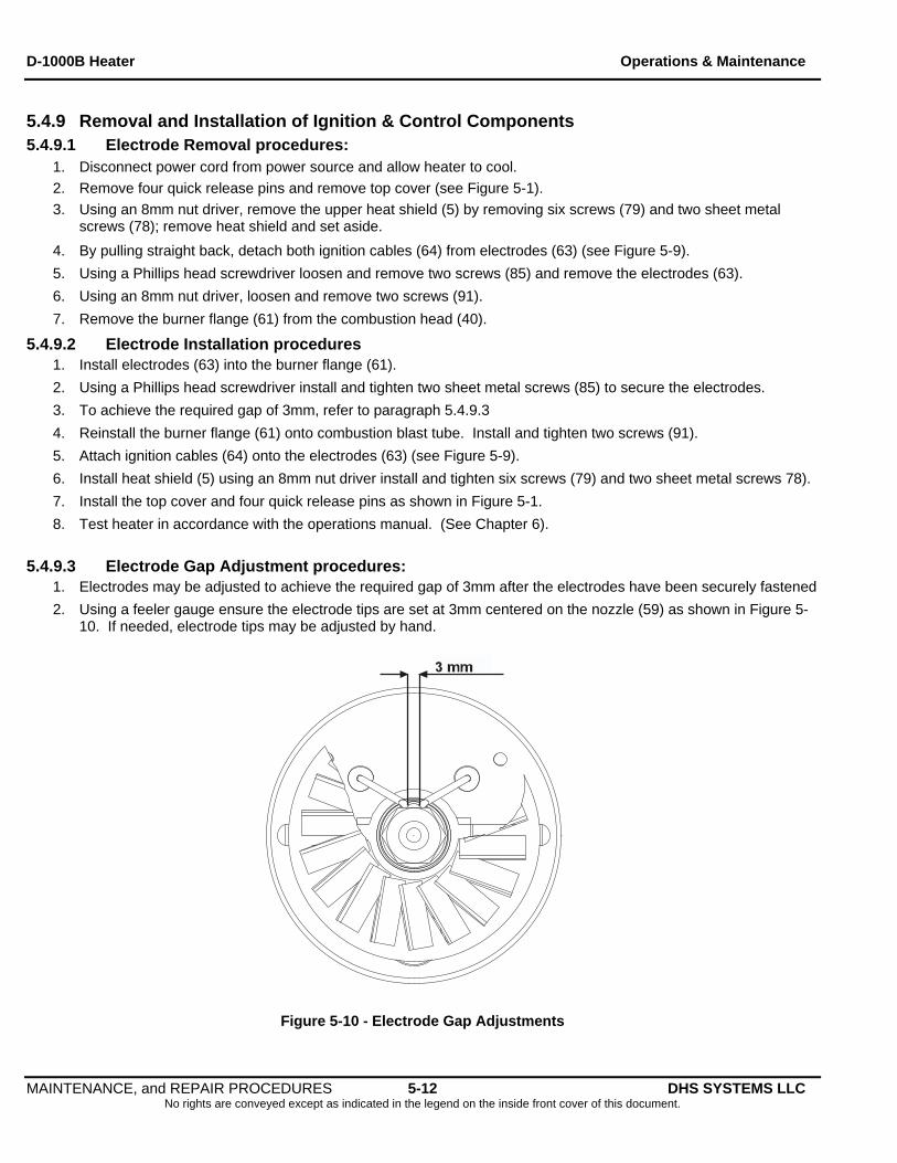
5.4.9.3 Electrode Gap Adjustment procedures: 1. Electrodes may be adjusted to achieve the required gap of 3mm after the electrodes have been securely fastened
2. Using a feeler gauge ensure the electrode tips are set at 3mm centered on the nozzle (59) as shown in Figure 5-10. If needed, electrode tips may be adjusted by hand.
Figure 5-10 - Electrode Gap Adjustments
MAINTENANCE, and REPAIR PROCEDURES 5-12 DHS SYSTEMS LLC No rights are conveyed except as indicated in the legend on the inside front cover of this document.
D-1000B Heater Operations & Maintenance
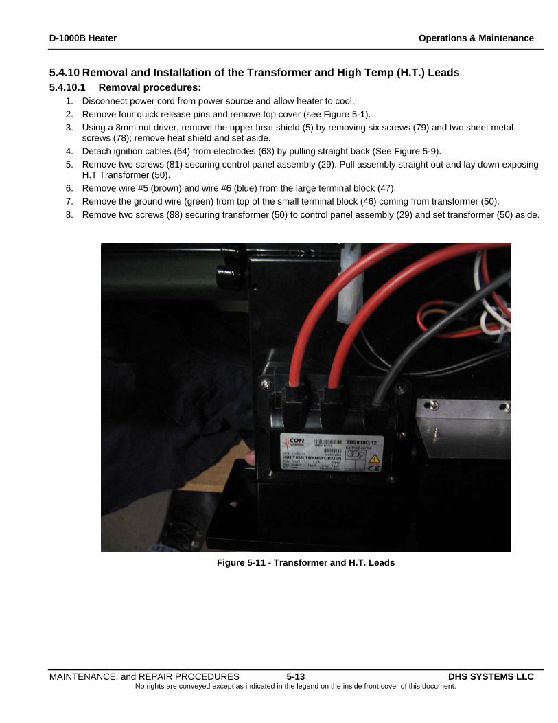
5.4.10 Removal and Installation of the Transformer and High Temp (H.T.) Leads 5.4.10.1 Removal procedures:
1. Disconnect power cord from power source and allow heater to cool.
2. Remove four quick release pins and remove top cover (see Figure 5-1).
3. Using a 8mm nut driver, remove the upper heat shield (5) by removing six screws (79) and two sheet metal screws (78); remove heat shield and set aside.
4. Detach ignition cables (64) from electrodes (63) by pulling straight back (See Figure 5-9).
5. Remove two screws (81) securing control panel assembly (29). Pull assembly straight out and lay down exposing H.T Transformer (50).
6. Remove wire #5 (brown) and wire #6 (blue) from the large terminal block (47).
7. Remove the ground wire (green) from top of the small terminal block (46) coming from transformer (50).
8. Remove two screws (88) securing transformer (50) to control panel assembly (29) and set transformer (50) aside.
Figure 5-11 - Transformer and H.T. Leads
MAINTENANCE, and REPAIR PROCEDURES 5-13 DHS SYSTEMS LLC No rights are conveyed except as indicated in the legend on the inside front cover of this document.
D-1000B Heater Operations & Maintenance
MAINTENANCE, and REPAIR PROCEDURES 5-14 DHS SYSTEMS LLC No rights are conveyed except as indicated in the legend on the inside front cover of this document.
5.4.10.2 Installation procedures: 1. Secure new transformer (50) onto Control Panel Assembly (29) with two screws (88).
2. Feed two red electrode wires (64) up through lower heat shield (6) and connect onto back of electrodes (63).
3. Attach wire #5 (brown) and wire #6 (blue) to the large terminal block (47).
4. Attach ground wire (green) to the top of the small terminal block (46).
5. Attach control panel assembly (29) to heater base (30) using two screws (81).
6. Install heat shield (5).
7. Using an 8mm nut driver, install and tighten six screws (79) and two sheet metal screws (78).
8. Install the top cover and four quick release pins as shown in Figure 5-1.
9. Test heater in accordance with the operations manual. (See Chapter 6).
D-1000B Heater Operations & Maintenance
5.4.11 Removal and Installation of the Photocell 5.4.11.1 Removal procedures:
1. Disconnect power cord from power source and allow heater to cool.
2. Remove four quick release pins and remove top cover (see Figure 5-1).
3. Using a 8mm nut driver, remove the upper heat shield (5) by removing six screws (79) and two sheet metal screws (78); remove heat shield and set aside.
4. Remove two screws (81) securing Control Panel Assembly (29). Pull assembly straight out and lay down.
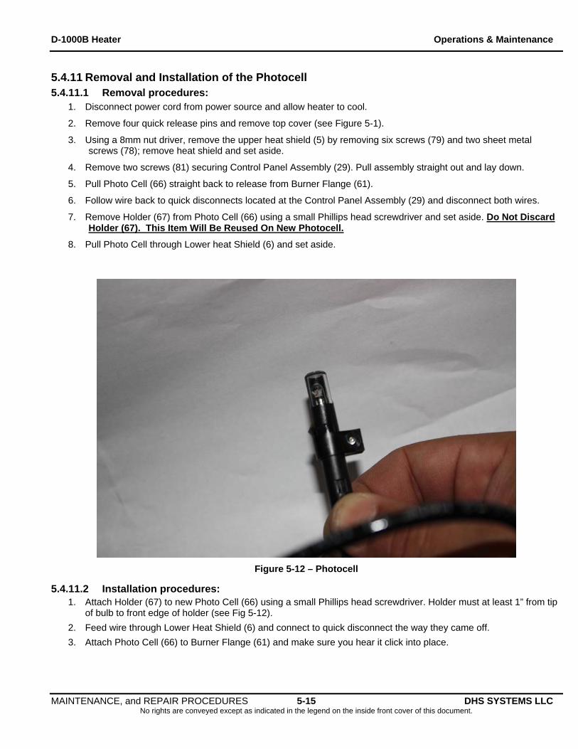
5. Pull Photo Cell (66) straight back to release from Burner Flange (61).
6. Follow wire back to quick disconnects located at the Control Panel Assembly (29) and disconnect both wires.
7. Remove Holder (67) from Photo Cell (66) using a small Phillips head screwdriver and set aside. Do Not Discard Holder (67). This Item Will Be Reused On New Photocell.
8. Pull Photo Cell through Lower heat Shield (6) and set aside.
Figure 5-12 – Photocell
5.4.11.2 Installation procedures: 1. Attach Holder (67) to new Photo Cell (66) using a small Phillips head screwdriver. Holder must at least 1” from tip
of bulb to front edge of holder (see Fig 5-12).
2. Feed wire through Lower Heat Shield (6) and connect to quick disconnect the way they came off.
3. Attach Photo Cell (66) to Burner Flange (61) and make sure you hear it click into place.
MAINTENANCE, and REPAIR PROCEDURES 5-15 DHS SYSTEMS LLC No rights are conveyed except as indicated in the legend on the inside front cover of this document.
D-1000B Heater Operations & Maintenance
Installation of the Photocell Continued
IMPORTANT If you do not hear it click you must adjust the holder (67).
Clear part of bulb should always face up when inserting into Burner Flange (61).
4. Attach Control Panel Assembly (29) to Heater base (30) using two screws (81).
5. Install heat shield (5).
6. Using an 8mm nut driver, install and tighten six screws (79) and two sheet metal screws (78).
7. Install the top cover and four quick release pins as shown in Figure 5-1.
8. Test heater in accordance with the operations manual. (See Chapter 6).
MAINTENANCE, and REPAIR PROCEDURES 5-16 DHS SYSTEMS LLC No rights are conveyed except as indicated in the legend on the inside front cover of this document.
D-1000B Heater Operations & Maintenance
TEST PROCEDURES 6-1 DHS SYSTEMS LLC No rights are conveyed except as indicated in the legend on the inside front cover of this document.
6. TEST PROCEDURES
6.1 Maintenance Repair Test Procedures 1. Remove all fabric covers and accessories bag (if attached) from heater.
2. Install exhaust Stack.
3. Add fuel; run heater outdoors in accordance to start up procedures for ten minutes.
4. Service heater if any problems and or leaks are noted.
6.2 Thermostat / CO Detector Control Device Test 1. Connect heater to a grounded power supply and start the heater.
2. Attach and hand tighten the Thermostat / CO Detector 5-pin connector to the control panel (see figure 4-1, item #3).
3. Adjust the thermostat to the lowest temperature setting; the heater should turn off.
4. Adjust the thermostat to the desired temperature setting and the heater should turn on.
5. If thermostat/CO detector does not work, turn off heater, loosen and disconnect the 5-pin connector.
6. Replace the thermostat/CO detector control device and repeat step 1 thru step 4.
WARNING
The following two tests, Smoke Test and Fuel Pressure Test, must be ONLY performed by a trained DHS Technician.
6.3 Smoke Test 1. Refer to Chapter 4 for start up procedures; operate heater for five minutes or until combustion chamber is
hot.
2. Loosen knurled knob clamp on tester as shown in Figure 6-1.
3. Using a piece of filter paper (included with Smoke Tester), insert the filter paper strip in slot and tighten knurled knob clamp.
4. Insert sampling tube into the exhaust stack.
5. Pull the tester handle through 10 full strokes.
6. Remove sampling tube from the exhaust stack and secure in holder on smoke tester.
7. Loosen knurled knob clamp and remove filter paper. Refer to Table 6-1 for smoke spot color test.
8. Take additional samples, if necessary, insert the same filter paper strip into slot.
9. Position filter paper in slot not to cover the previous smoke spot so that the previous spot is visible outside the slot.
10. Repeat steps 4, 5, 6, and 7 above.
D-1000B Heater Operations & Maintenance
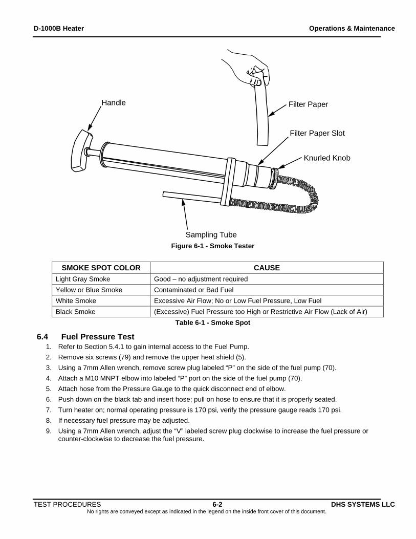
Handle
Filter Paper Slot
Knurled Knob
Sampling Tube
Filter Paper
Figure 6-1 - Smoke Tester
SMOKE SPOT COLOR CAUSE
Light Gray Smoke Good – no adjustment required
Yellow or Blue Smoke Contaminated or Bad Fuel
White Smoke Excessive Air Flow; No or Low Fuel Pressure, Low Fuel
Black Smoke (Excessive) Fuel Pressure too High or Restrictive Air Flow (Lack of Air)
Table 6-1 - Smoke Spot
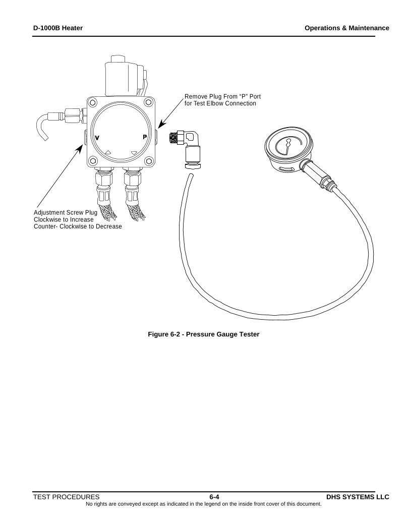
6.4 Fuel Pressure Test 1. Refer to Section 5.4.1 to gain internal access to the Fuel Pump.
2. Remove six screws (79) and remove the upper heat shield (5).
3. Using a 7mm Allen wrench, remove screw plug labeled “P” on the side of the fuel pump (70).
4. Attach a M10 MNPT elbow into labeled “P” port on the side of the fuel pump (70).
5. Attach hose from the Pressure Gauge to the quick disconnect end of elbow.
6. Push down on the black tab and insert hose; pull on hose to ensure that it is properly seated.
7. Turn heater on; normal operating pressure is 170 psi, verify the pressure gauge reads 170 psi.
8. If necessary fuel pressure may be adjusted.
9. Using a 7mm Allen wrench, adjust the “V” labeled screw plug clockwise to increase the fuel pressure or counter-clockwise to decrease the fuel pressure.
TEST PROCEDURES 6-2 DHS SYSTEMS LLC No rights are conveyed except as indicated in the legend on the inside front cover of this document.
D-1000B Heater Operations & Maintenance
10. Disconnect pressure gauge hose by pushing down on the black tab at the M10 MNPT elbow and pulling
hose out. There may be pressure and or fuel still in the hose; use caution and have a rag or container to collect fuel.
NOTE
Always start adjustments low and then increase
CAUTION Pressure gauge and hose may be under pressure. Use caution when depressing black
tab and removing hose
11. Loosen and remove the M10 MNPT elbow from fuel pump (70).
12. Using a 7mm Allen wrench, reinstall the screw plug into the “P” labeled port on the side of the fuel pump (70).
13. Wipe up any spilled fuel.
14. Install the upper heat shield (5).
15. Install and tighten six screws (79) to secure the upper heat shield (5).
16. Reinstall top cover and four quick release pins.
17. Test heater in accordance with operations manual (see section 6-1) and check for leaks.
TEST PROCEDURES 6-3 DHS SYSTEMS LLC No rights are conveyed except as indicated in the legend on the inside front cover of this document.
D-1000B Heater Operations & Maintenance
Remove Plug From “P” Portfor Test Elbow Connection
Adjustment Screw PlugClockwise to IncreaseCounter- Clockwise to Decrease
Figure 6-2 - Pressure Gauge Tester
TEST PROCEDURES 6-4 DHS SYSTEMS LLC No rights are conveyed except as indicated in the legend on the inside front cover of this document.
D-1000B Heater Operations & Maintenance
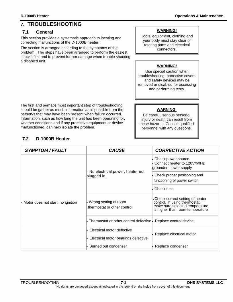
7. TROUBLESHOOTING WARNING!
Tools, equipment, clothing and your body must stay clear of rotating parts and electrical
connectors.
7.1 General This section provides a systematic approach to locating and correcting malfunctions of the D-1000B heater.
The section is arranged according to the symptoms of the problem. The steps have been arranged to perform the easiest checks first and to prevent further damage when trouble shooting a disabled unit.
Use special caution when troubleshooting; protective covers
and safety devices may be removed or disabled for accessing
and performing tests.
WARNING!
Be careful, serious personal injury or death can result from
these hazards. Consult qualified personnel with any questions.
WARNING!
The first and perhaps most important step of troubleshooting should be gather as much information as is possible from the person/s that may have been present when failure occurred. Information, such as how long the unit has been operating for, weather conditions and if any protective equipment or device malfunctioned, can help isolate the problem.
7.2 D-1000B Heater
TROUBLESHOOTING 7-1 DHS SYSTEMS LLC No rights are conveyed except as indicated in the legend on the inside front cover of this document.
SYMPTOM / FAULT CAUSE CORRECTIVE ACTION
Check power source. Connect heater to 120V/60Hz grounded power supply
Check proper positioning and functioning of power switch
No electrical power, heater not plugged in.
Check fuse
Wrong setting of room thermostat or other control
Check correct setting of heater control. If using thermostat, make sure selected temperature is higher than room temperature
Thermostat or other control defective Replace control device
Electrical motor defective
Electrical motor bearings defective Replace electrical motor
Motor does not start, no ignition
Burned out condenser Replace condenser
D-1000B Heater Operations & Maintenance
TROUBLESHOOTING 7-2 DHS SYSTEMS LLC No rights are conveyed except as indicated in the legend on the inside front cover of this document.
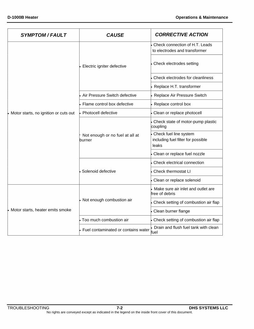
SYMPTOM / FAULT CAUSE CORRECTIVE ACTION
Check connection of H.T. Leads to electrodes and transformer
Check electrodes setting
Check electrodes for cleanliness
Electric igniter defective
Replace H.T. transformer
Air Pressure Switch defective Replace Air Pressure Switch
Flame control box defective Replace control box
Photocell defective Clean or replace photocell
Check state of motor-pump plastic coupling
Check fuel line system including fuel filter for possible leaks
Not enough or no fuel at all at burner
Clean or replace fuel nozzle
Check electrical connection
Check thermostat LI
Motor starts, no ignition or cuts out
Solenoid defective
Clean or replace solenoid
Make sure air inlet and outlet are free of debris
Check setting of combustion air flap Not enough combustion air
Clean burner flange
Too much combustion air Check setting of combustion air flap
Motor starts, heater emits smoke
Fuel contaminated or contains water Drain and flush fuel tank with clean fuel
D-1000B Heater Operations & Maintenance
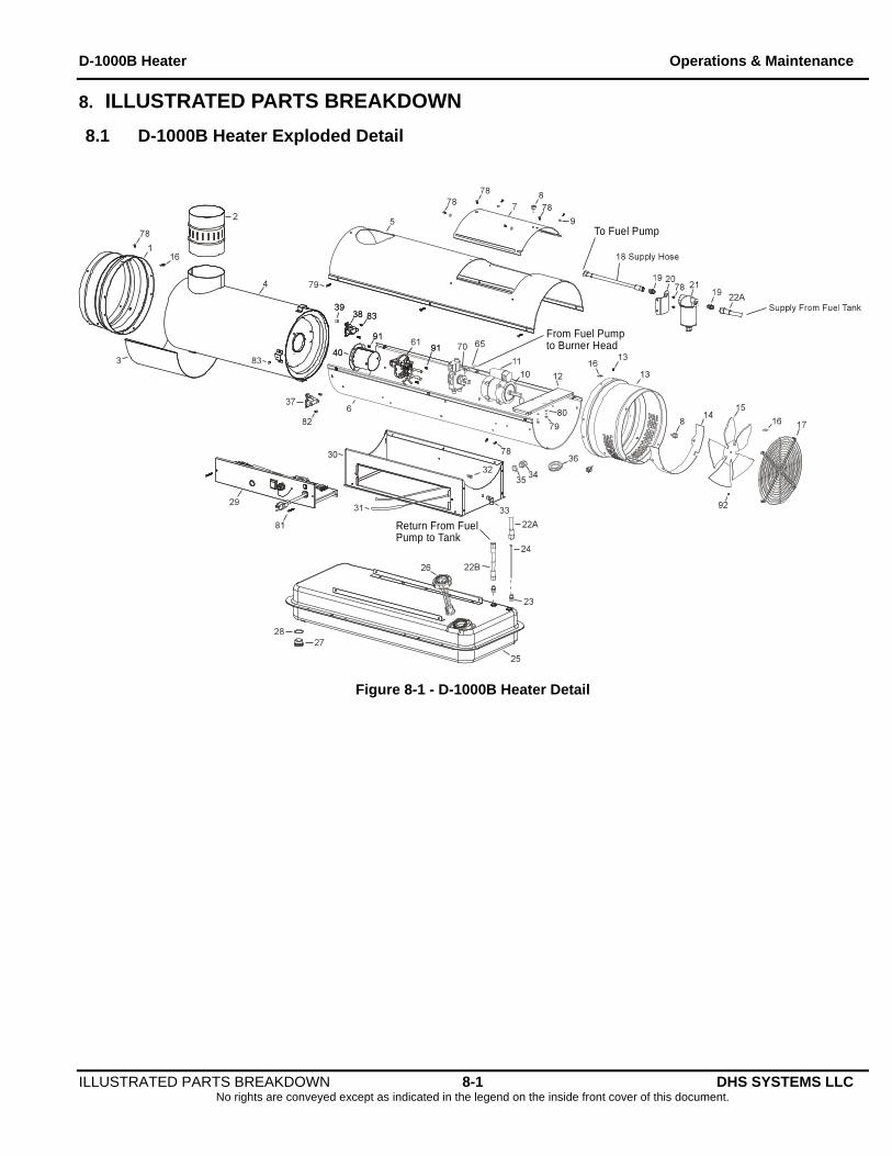
8. ILLUSTRATED PARTS BREAKDOWN
8.1 D-1000B Heater Exploded Detail
To Fuel Pump
Return From FuelPump to Tank
From Fuel Pumpto Burner Head
Figure 8-1 - D-1000B Heater Detail
ILLUSTRATED PARTS BREAKDOWN 8-1 DHS SYSTEMS LLC No rights are conveyed except as indicated in the legend on the inside front cover of this document.
D-1000B Heater Operations & Maintenance
8.2 Burner Head and Nozzle Assembly Exploded View
To Ground Terminal Board
Figure 8-2 – Burner Head and Nozzle Assembly Detail
ILLUSTRATED PARTS BREAKDOWN 8-2 DHS SYSTEMS LLC No rights are conveyed except as indicated in the legend on the inside front cover of this document.
D-1000B Heater Operations & Maintenance
8.3 Fuel Pump Assembly Exploded View
Figure 8-3 – Fuel Pump Assembly Detail
ILLUSTRATED PARTS BREAKDOWN 8-3 DHS SYSTEMS LLC No rights are conveyed except as indicated in the legend on the inside front cover of this document.
D-1000B Heater Operations & Maintenance
8.4 Pre-Heated Fuel Filter Exploded View
Figure 8-4 – Pre-Heated Fuel Filter Detail
ILLUSTRATED PARTS BREAKDOWN 8-4 DHS SYSTEMS LLC No rights are conveyed except as indicated in the legend on the inside front cover of this document.
D-1000B Heater Operations & Maintenance
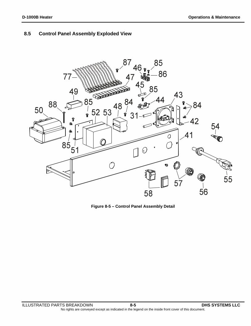
8.5 Control Panel Assembly Exploded View
Figure 8-5 – Control Panel Assembly Detail
ILLUSTRATED PARTS BREAKDOWN 8-5 DHS SYSTEMS LLC No rights are conveyed except as indicated in the legend on the inside front cover of this document.
D-1000B Heater Operations & Maintenance
ILLUSTRATED PARTS BREAKDOWN 8-6 DHS SYSTEMS LLC No rights are conveyed except as indicated in the legend on the inside front cover of this document.
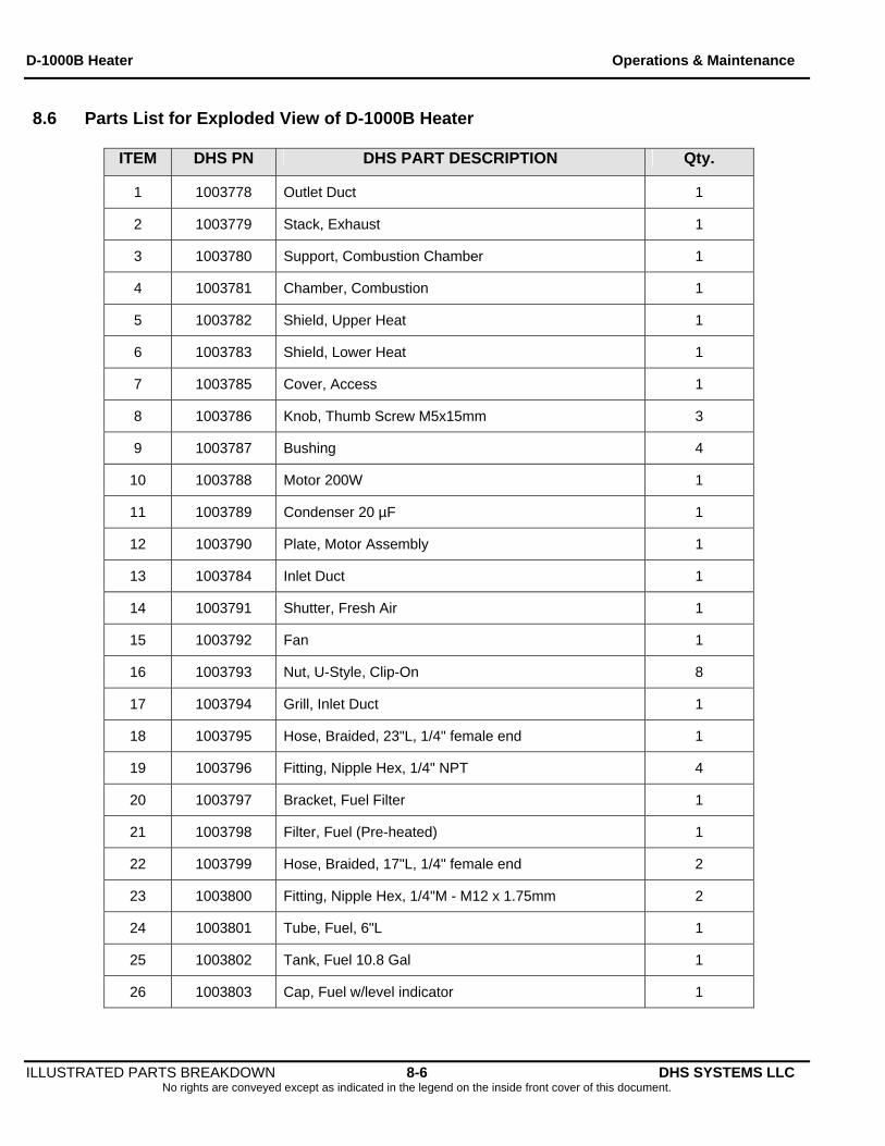
8.6 Parts List for Exploded View of D-1000B Heater
ITEM DHS PN DHS PART DESCRIPTION Qty.
1 1003778 Outlet Duct 1
2 1003779 Stack, Exhaust 1
3 1003780 Support, Combustion Chamber 1
4 1003781 Chamber, Combustion 1
5 1003782 Shield, Upper Heat 1
6 1003783 Shield, Lower Heat 1
7 1003785 Cover, Access 1
8 1003786 Knob, Thumb Screw M5x15mm 3
9 1003787 Bushing 4
10 1003788 Motor 200W 1
11 1003789 Condenser 20 µF 1
12 1003790 Plate, Motor Assembly 1
13 1003784 Inlet Duct 1
14 1003791 Shutter, Fresh Air 1
15 1003792 Fan 1
16 1003793 Nut, U-Style, Clip-On 8
17 1003794 Grill, Inlet Duct 1
18 1003795 Hose, Braided, 23"L, 1/4" female end 1
19 1003796 Fitting, Nipple Hex, 1/4" NPT 4
20 1003797 Bracket, Fuel Filter 1
21 1003798 Filter, Fuel (Pre-heated) 1
22 1003799 Hose, Braided, 17"L, 1/4" female end 2
23 1003800 Fitting, Nipple Hex, 1/4"M - M12 x 1.75mm 2
24 1003801 Tube, Fuel, 6"L 1
25 1003802 Tank, Fuel 10.8 Gal 1
26 1003803 Cap, Fuel w/level indicator 1
D-1000B Heater Operations & Maintenance
ILLUSTRATED PARTS BREAKDOWN 8-7 DHS SYSTEMS LLC No rights are conveyed except as indicated in the legend on the inside front cover of this document.
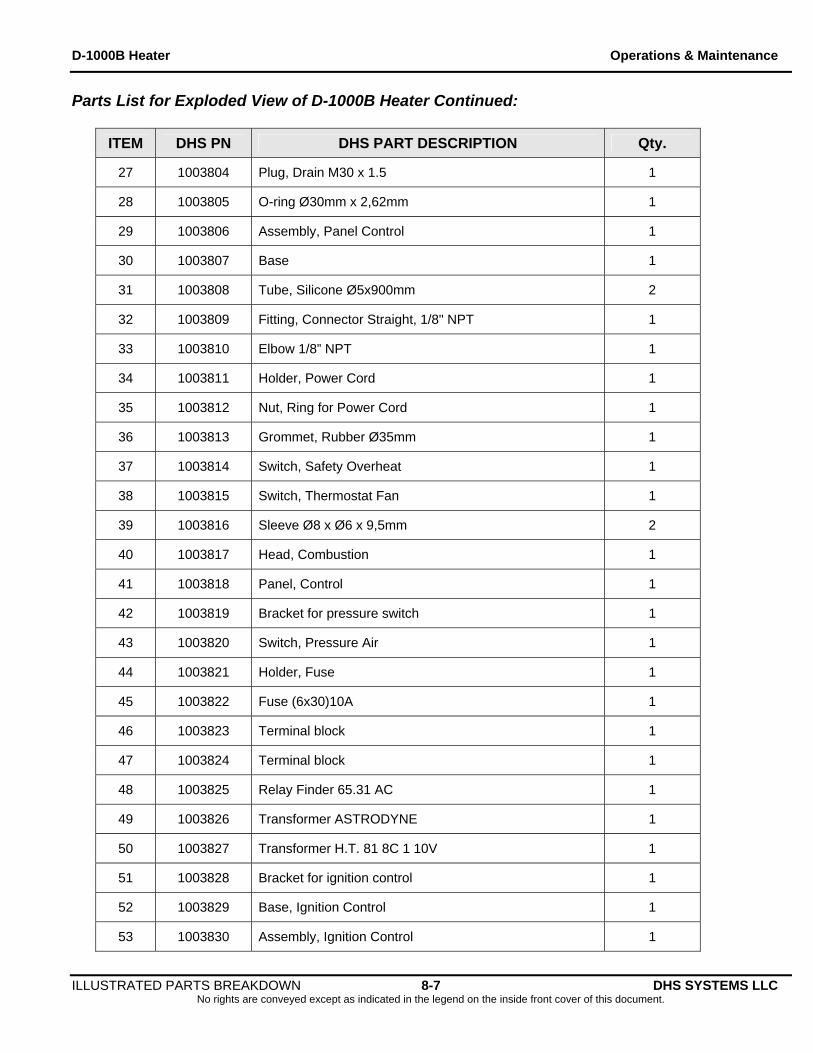
Parts List for Exploded View of D-1000B Heater Continued:
ITEM DHS PN DHS PART DESCRIPTION Qty.
27 1003804 Plug, Drain M30 x 1.5 1
28 1003805 O-ring Ø30mm x 2,62mm 1
29 1003806 Assembly, Panel Control 1
30 1003807 Base 1
31 1003808 Tube, Silicone Ø5x900mm 2
32 1003809 Fitting, Connector Straight, 1/8" NPT 1
33 1003810 Elbow 1/8” NPT 1
34 1003811 Holder, Power Cord 1
35 1003812 Nut, Ring for Power Cord 1
36 1003813 Grommet, Rubber Ø35mm 1
37 1003814 Switch, Safety Overheat 1
38 1003815 Switch, Thermostat Fan 1
39 1003816 Sleeve Ø8 x Ø6 x 9,5mm 2
40 1003817 Head, Combustion 1
41 1003818 Panel, Control 1
42 1003819 Bracket for pressure switch 1
43 1003820 Switch, Pressure Air 1
44 1003821 Holder, Fuse 1
45 1003822 Fuse (6x30)10A 1
46 1003823 Terminal block 1
47 1003824 Terminal block 1
48 1003825 Relay Finder 65.31 AC 1
49 1003826 Transformer ASTRODYNE 1
50 1003827 Transformer H.T. 81 8C 1 10V 1
51 1003828 Bracket for ignition control 1
52 1003829 Base, Ignition Control 1
53 1003830 Assembly, Ignition Control 1
D-1000B Heater Operations & Maintenance
ILLUSTRATED PARTS BREAKDOWN 8-8 DHS SYSTEMS LLC No rights are conveyed except as indicated in the legend on the inside front cover of this document.
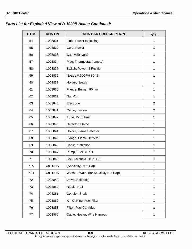
Parts List for Exploded View of D-1000B Heater Continued:
ITEM DHS PN DHS PART DESCRIPTION Qty.
54 1003831 Light, Power Indicating 1
55 1003832 Cord, Power 1
56 1003833 Cap, w/lanyard 1
57 1003834 Plug, Thermostat (remote) 1
58 1003835 Switch, Power, 3-Position 1
59 1003836 Nozzle 0.60GPH 80° S 1
60 1003837 Holder, Nozzle 1
61 1003838 Flange, Burner, 80mm 1
62 1003839 Nut M14 1
63 1003840 Electrode 2
64 1003841 Cable, Ignition 2
65 1003842 Tube, Micro Fuel 1
66 1003843 Detector, Flame 1
67 1003844 Holder, Flame Detector 1
68 1003845 Flange, Flame Detector 1
69 1003846 Cable, protection 1
70 1003847 Pump, Fuel BFP01 1
71 1003848 Coil, Solenoid, BFP11-21 1
71A Call DHS (Specialty) Nut, Cap 1
71B Call DHS Washer, Wave (for Specialty Nut Cap) 1
72 1003849 Valve, Solenoid 1
73 1003850 Nipple, Hex 1
74 1003851 Coupler, Shaft 1
75 1003852 Kit, O'-Ring, Fuel Filter 1
76 1003853 Filter, Fuel Cartridge 1
77 1003862 Cable, Heater, Wire Harness 1
D-1000B Heater Operations & Maintenance
ILLUSTRATED PARTS BREAKDOWN 8-9 DHS SYSTEMS LLC No rights are conveyed except as indicated in the legend on the inside front cover of this document.
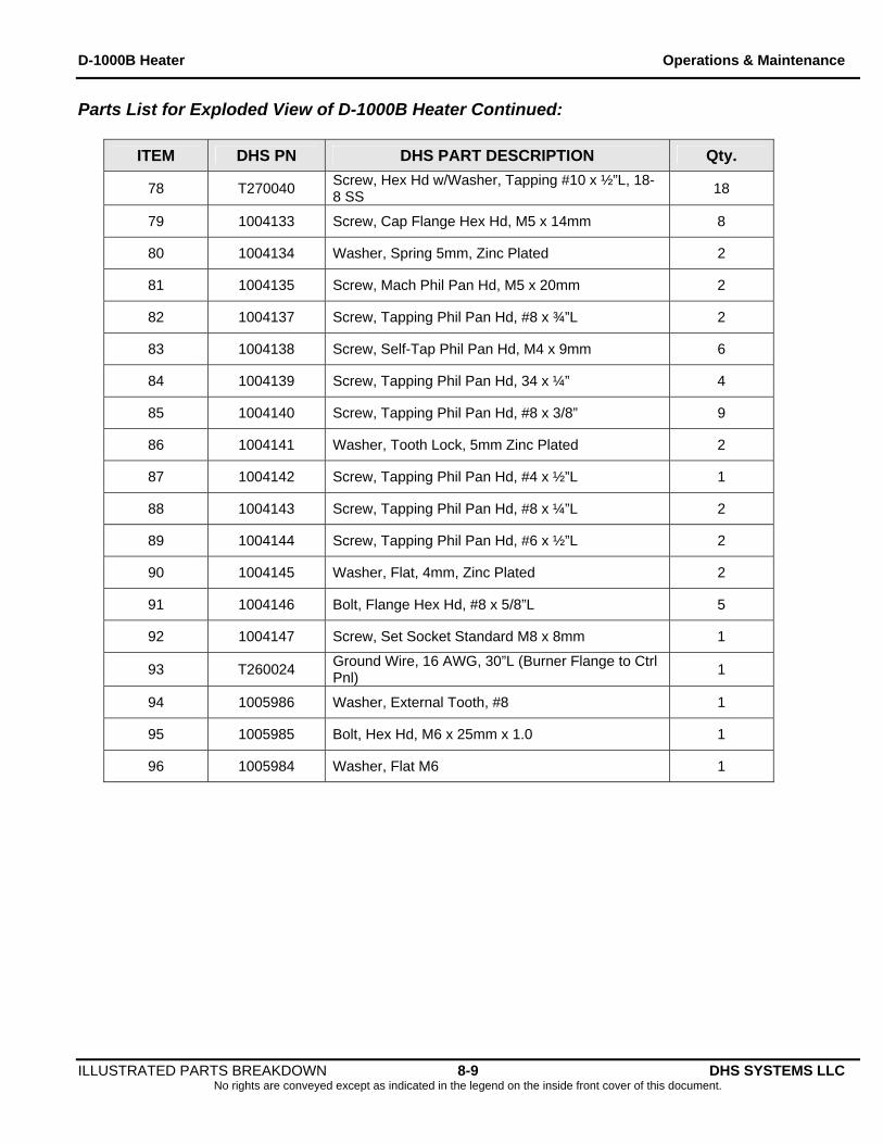
Parts List for Exploded View of D-1000B Heater Continued:
ITEM DHS PN DHS PART DESCRIPTION Qty.
78 T270040 Screw, Hex Hd w/Washer, Tapping #10 x ½”L, 18-8 SS
18
79 1004133 Screw, Cap Flange Hex Hd, M5 x 14mm 8
80 1004134 Washer, Spring 5mm, Zinc Plated 2
81 1004135 Screw, Mach Phil Pan Hd, M5 x 20mm 2
82 1004137 Screw, Tapping Phil Pan Hd, #8 x ¾”L 2
83 1004138 Screw, Self-Tap Phil Pan Hd, M4 x 9mm 6
84 1004139 Screw, Tapping Phil Pan Hd, 34 x ¼” 4
85 1004140 Screw, Tapping Phil Pan Hd, #8 x 3/8” 9
86 1004141 Washer, Tooth Lock, 5mm Zinc Plated 2
87 1004142 Screw, Tapping Phil Pan Hd, #4 x ½”L 1
88 1004143 Screw, Tapping Phil Pan Hd, #8 x ¼”L 2
89 1004144 Screw, Tapping Phil Pan Hd, #6 x ½”L 2
90 1004145 Washer, Flat, 4mm, Zinc Plated 2
91 1004146 Bolt, Flange Hex Hd, #8 x 5/8”L 5
92 1004147 Screw, Set Socket Standard M8 x 8mm 1
93 T260024 Ground Wire, 16 AWG, 30”L (Burner Flange to Ctrl Pnl)
1
94 1005986 Washer, External Tooth, #8 1
95 1005985 Bolt, Hex Hd, M6 x 25mm x 1.0 1
96 1005984 Washer, Flat M6 1
D-1000B Heater Operations & Maintenance
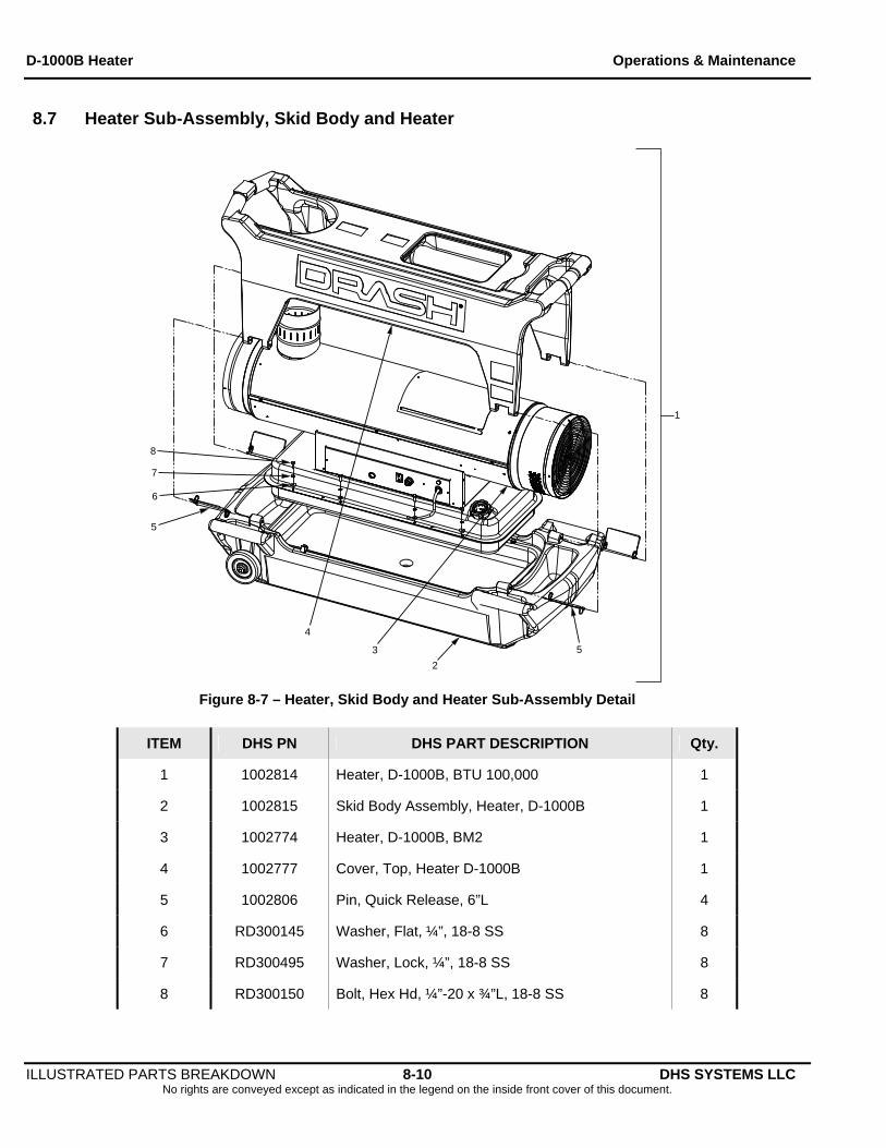
8.7 Heater Sub-Assembly, Skid Body and Heater
2
3
4
5
5
6
7
8
1
Figure 8-7 – Heater, Skid Body and Heater Sub-Assembly Detail
ITEM DHS PN DHS PART DESCRIPTION Qty.
1 1002814 Heater, D-1000B, BTU 100,000 1
2 1002815 Skid Body Assembly, Heater, D-1000B 1
3 1002774 Heater, D-1000B, BM2 1
4 1002777 Cover, Top, Heater D-1000B 1
5 1002806 Pin, Quick Release, 6”L 4
6 RD300145 Washer, Flat, ¼”, 18-8 SS 8
7 RD300495 Washer, Lock, ¼”, 18-8 SS 8
8 RD300150 Bolt, Hex Hd, ¼”-20 x ¾”L, 18-8 SS 8
ILLUSTRATED PARTS BREAKDOWN 8-10 DHS SYSTEMS LLC No rights are conveyed except as indicated in the legend on the inside front cover of this document.
D-1000B Heater Operations & Maintenance
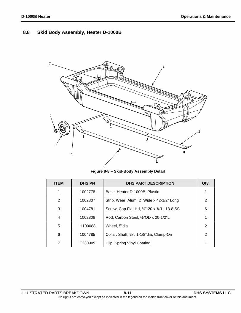
8.8 Skid Body Assembly, Heater D-1000B
1
2
3
4
5
6
7
Figure 8-8 – Skid-Body Assembly Detail
ITEM DHS PN DHS PART DESCRIPTION Qty.
1 1002778 Base, Heater D-1000B, Plastic 1
2 1002807 Strip, Wear, Alum, 2” Wide x 42-1/2” Long 2
3 1004781 Screw, Cap Flat Hd, ¼”-20 x ¾”L, 18-8 SS 6
4 1002808 Rod, Carbon Steel, ½”OD x 20-1/2”L 1
5 H100088 Wheel, 5”dia 2
6 1004785 Collar, Shaft, ½”, 1-1/8”dia, Clamp-On 2
7 T230909 Clip, Spring Vinyl Coating 1
ILLUSTRATED PARTS BREAKDOWN 8-11 DHS SYSTEMS LLC No rights are conveyed except as indicated in the legend on the inside front cover of this document.
D-1000B Heater Operations & Maintenance
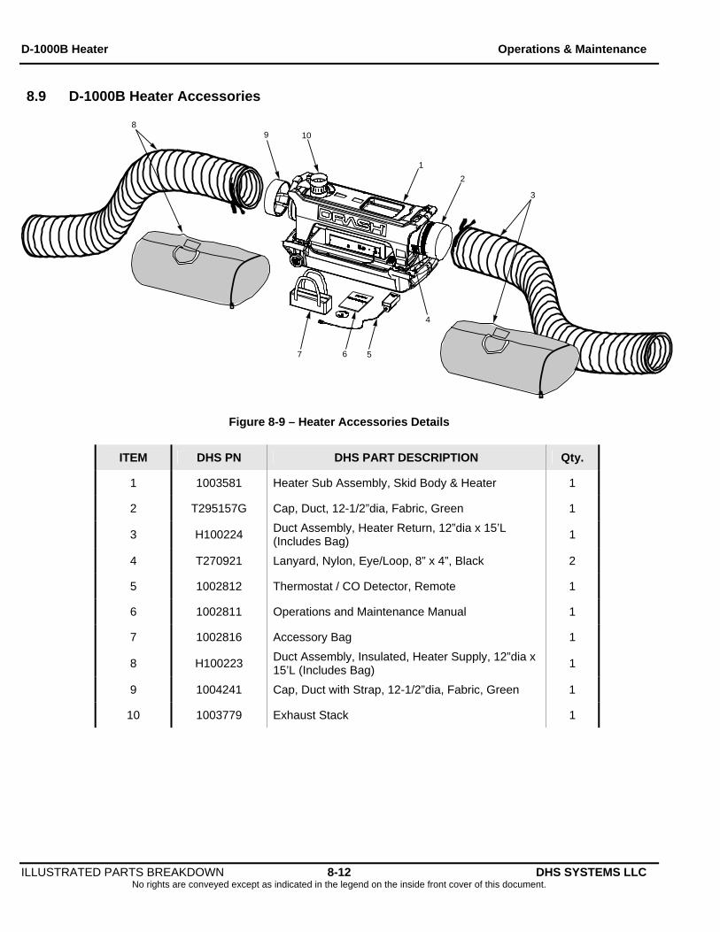
8.9 D-1000B Heater Accessories
1
2
3
4
7
89
5
10
6
Figure 8-9 – Heater Accessories Details
ITEM DHS PN DHS PART DESCRIPTION Qty.
1 1003581 Heater Sub Assembly, Skid Body & Heater 1
2 T295157G Cap, Duct, 12-1/2”dia, Fabric, Green 1
3 H100224 Duct Assembly, Heater Return, 12”dia x 15’L (Includes Bag)
1
4 T270921 Lanyard, Nylon, Eye/Loop, 8” x 4”, Black 2
5 1002812 Thermostat / CO Detector, Remote 1
6 1002811 Operations and Maintenance Manual 1
7 1002816 Accessory Bag 1
8 H100223 Duct Assembly, Insulated, Heater Supply, 12”dia x 15’L (Includes Bag)
1
9 1004241 Cap, Duct with Strap, 12-1/2”dia, Fabric, Green 1
10 1003779 Exhaust Stack 1
ILLUSTRATED PARTS BREAKDOWN 8-12 DHS SYSTEMS LLC No rights are conveyed except as indicated in the legend on the inside front cover of this document.
D-1000B Heater Operations & Maintenance
WARRANTY 9-1 DHS SYSTEMS LLC No rights are conveyed except as indicated in the legend on the inside front cover of this document.
9. WARRANTY
DHS SYSTEMS LLC LIMITED WARRANTY
DHS Systems LLC provides a limited warranty that all DRASH (Deployable Rapid Assembly Shelter) products shall be free from defects in materials and workmanship for the period of time shown in the Warranty Schedule below. This warranty shall protect the original purchaser and shall inure to the benefit of any additional end users of the product, but in no event shall the warranty extend for a period of time in excess of that shown in the Warranty Schedule shown below.
WARRANTY SCHEDULE
DRASH Shelters and Shelter Accessories: 60 Months
DRASH UST Trailers and Trailer Accessories: 12 Months
DRASH Heaters and Heater Accessories: 12 Months
DRASH Power Distribution Unit (PDU): 12 Months
The warranty period reflected in the above Warranty Schedule shall begin on the date of original shipment to the original purchaser.
The liability of DHS Systems LLC hereunder is limited to the labor and parts required to repair or replace any defective part or other covered defect in material or workmanship. Damage due to excessive wear and tear, improper use or carelessness is not covered under this limited warranty. Any attempt to repair a defect by a party not authorized by DHS Systems LLC may void this warranty. This warranty is contingent upon a) proper operation of the products in accordance with the operating instructions provided and b) proper maintenance and care of the equipment in accordance with the operating instructions provided. Warranty claims must contain a detailed explanation of the defect and be supported by summary extracts of pertinent service and maintenance records, if applicable. DHS Systems LLC shall have the right to examine the alleged defect and may require the claimant at the claimant’s expense, to return the product for such an examination, if practicable. In the event the claim is validated, claimant shall be reimbursed for the cost of shipping the product to DHS Systems LLC. If DHS Systems LLC personnel are required to visit the claimant’s site to validate and claim and such claim is not validated, all expenses for travel and accommodations will be charged to the claimant. Any warranty claims must be filed with DHS Systems LLC within 90 days after the alleged defect has first been identified. All claims must be mailed or faxed to the following:
DHS SYSTEMS LLC 33 Kings Highway
Orangeburg, NY 10962-1802 Attn: Customer Service, Logistics
Phone: 845-359-6066 Fax: 845-365-2114 Email: [email protected] This warranty is the sole warranty provided for the products listed herein. DHS Systems LLC provides no other express or implied warranty with respect to these products (including but not limited to no implied warranty of merchantability or fitness for a particular purpose).
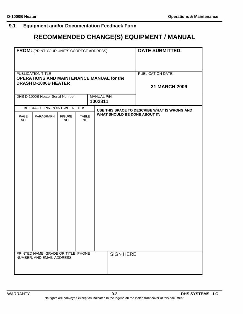
D-1000B Heater Operations & Maintenance
WARRANTY 9-2 DHS SYSTEMS LLC No rights are conveyed except as indicated in the legend on the inside front cover of this document.
9.1 Equipment and/or Documentation Feedback Form
RECOMMENDED CHANGE(S) EQUIPMENT / MANUAL
FROM: (PRINT YOUR UNIT’S CORRECT ADDRESS) DATE SUBMITTED:
PUBLICATION TITLE OPERATIONS AND MAINTENANCE MANUAL for the DRASH D-1000B HEATER DHS D-1000B Heater Serial Number MANUAL P/N:
1002811
PUBLICATION DATE
31 MARCH 2009
BE EXACT PIN-POINT WHERE IT IS
PAGE NO
PARAGRAPH FIGURE NO
TABLE NO
USE THIS SPACE TO DESCRIBE WHAT IS WRONG AND WHAT SHOULD BE DONE ABOUT IT:
PRINTED NAME, GRADE OR TITLE, PHONE NUMBER, AND EMAIL ADDRESS
SIGN HERE
D-1000B Heater Operations & Maintenance
(fold) Return Address:
DHS Logistics 33 Kings Highway
Orangeburg, NY 10962
Place Stamp Here
(fold)
WARRANTY 9-3 DHS SYSTEMS LLC No rights are conveyed except as indicated in the legend on the inside front cover of this document.